unclassified - defense technical information center · performing organization name 10.and address...
TRANSCRIPT

UNCLASSIFIED SECURITY CLASSIFICATION OF THIS PAGE (Wtimn Dmtm Enfrtd)
REPORT DOCUMENTATION PAGE READ INSTRUCTIONS BEFORE COMPLETING FORM
1. REPORT NUMBER 2. GOVT ACCESSION NO 3. RECIPIENT'S CATALOG NUMBER
«. TITLE f«nd 5ufc(l(leJ
F/A-1'8 AN/APG-6 5 Radar Case Study Report (IDA/OSD R&M Study)
5. TYPE OF REPORT & PERIOD COVERED
Final July 1982 - August 1983
6. PERFORMING ORG. REPORT NUMBER
IDA Record DocumentD-20 7. AUTHORf«J
Paul F. Goree, IDA R&M Case Study Director
8. CONTRACT OR GRANT NUMBERC«;
MDA 903 79 C 0018
9. PERFORMING ORGANIZATION NAME AND ADDRESS
Institute for Defense Analyses 1801 N, Beauregard Street Alexandria, VA 22311
10. PROGRAM ELEMENT. PROJECT, TASK AREA & WORK UNIT NUMBERS
Task T-2-126
I I. CONTROLLING OFFICE NAME AND ADDRESS
Office of the Assistant Secretary of Defense (MRA&L), The Pentagon WaRhin9t.nn. D.C. ZIl^^J^
12. REPORT DATE
August 1983 13. NUMBER OF PAGES
271
14. MONITORING AGENCY NAME & ADDRESSC/f dlllarmnt from ConlrolUnt Ofllct)
DoD-IDA Managonent Office 1801 N. Beauregard Street Alexandria, VA 22311
15. SECURITY CLASS, (ol Ih/a report)
UNCLASSIFIED 15«. DECLASSIFI CATION/DOWN GRADING
SCHEDULE ^/^
1«. DISTRIBUTION STATEMENT (ol thim Rtporl)
J^proved for public release; distribution unlimited.
17. DISTRIBUTION STATEMENT (ol Iht abilrmcl tnltrtd In Block 20, II dlllarent from Report)
None
18. SUPPLEMENTARY NOTES
N/A
19. KEY WORDS (Conllnum on tmvrrn* tidt II n«c«»««ry and Idantlly by block numbor)
reliability, maintainability, readiness, case study, program structuring, lessons learned, F/A-18, APG-65, radar
20. ABSTRACT (Conllnum on r^vram tldm It noc*ammrf mid Idmntity by block number)
This document records the activities and presents the findings of the F/A-18 AN/APG-65 Radar Case Study Working Group part of the IDA/OSD Relia- bility and Maintainability Study, conducted during the period fron July 1982 through August 1983.
DD ,: Fo«- ^473 EOmOM OF I MOV «5 IS OBSOLETE UNCLASSIFIED
SECURITY CLASSIFICATIOM OF THIS PAGE (Whtn Dmim Bnfrmd)

^l Cofly I 8 0* 200 ;op:cs
RESEARCH REPORTS DIVISION mSEARc: MAVAL POSTGRADUATE SCHOOL ^AVAL F,; ,. . MONTEREY, CALIFORNIA 93S43 WONTEREy, c/ii.Tc;;:,
IDA RECORD DOCUM:^NT D-20
■in
F/A-18 AN/APG-65 R.\DAR CASE STUDY REPORT (IDA/OSD R&M STUDY)
Paul F. Goree IDA R&M Case Study Director
"EA
f. JUN 1 3 1984-;■ i
August 1983
The views expressed within this document are those of the worl(ing group only. Publication of this document does not indicate endorse- ment by IDA, its start, or its sponsoring agencies.
Prepared for Office of the Under Secretary of Defense for Research and Engineering
and Office of the Assistant Secretary of Defense (Manpower, Reserve Affairs and Logistics)
Thi3 docuxQent has been ajSpioved for public release and sale; its distiibution is unlimited.
INSTITUTE FOR DEFENSE ANALYSES
IDA Log Me>. HQ Sj<25g30

-pa;!uij|un uoi}nq!4S!p :8se8|aj 3!iqnd J0| paAOJddv
'A3U86E )et|i }o uoujsod leiajp 8i|) Oupaiiaj se p9nj)suo3 eq s)U3)U03 em pinoiis jou 'esua^eo )0 )U8iu)jedea 8i|} Aq luamasjopua aieoipui ^)u saop tuauinaoQ pjooau vOi sjiii |0 uo|)e3!iqnd aqi -asueiSQ }0 (uaiuiJedaa aiji JO} 81.00 3 6^ £06 VQW penuos jspun papnpuoa SEM luauinDop siiii ui payodaj )|JOM aqj.
IDA RECORD DOCUMENT D-20
F/A-18 AN/APG-65 RADAR CASE STUDY REPORT (IDA/OSD R&M STUDY)
Paul F. Goree IDA R&M Case Study Director
August 1983
iD^q INSTITUTE FOR DEFENSE ANALYSES
1801 N. Beauregard Street, Alexandria, Virginia 22311 Contract MDA 903 79 C 0018
Task T-2-126
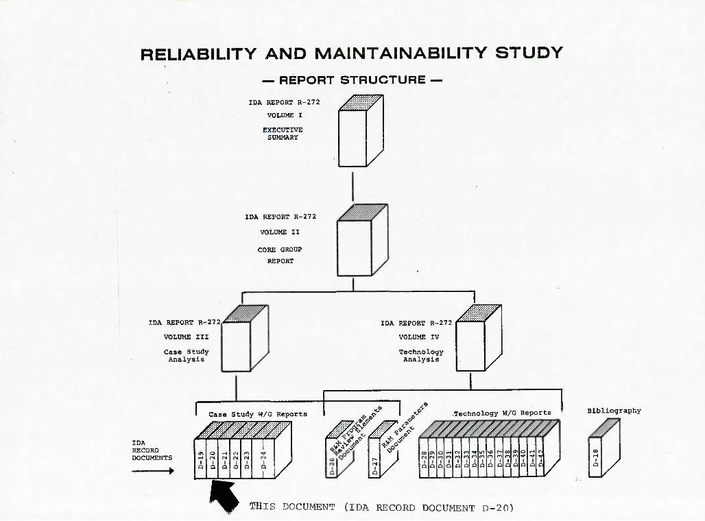
RELIABILITY AND MAINTAINABILITY STUDY
— REPORT STRUCTURE —
IDA REPORT R-272
VOLUME I
EXECUTIVE SUMMARY
IDA REPORT R-272
VOLUME II
CORE GROUP
REPORT
IDA REPORT R-272/!wffl
VOLUME III
Case Study Analysis
Case Study W/G Reports
IDA RECORD DOCUMENTS
r ///////A
/
/
IDA REPORT R-272
VOLUME IV
Technology Analysis
m o r^ <N n 1
^ (S O) r*i M Ol
a a a O O Q
1
Mfit^4 Technology W/G Reports Bibliography
13/
% Tins DOCUMENT (IDA RECORD DOCUMENT D-20)

PREFACE
As a result of the 1981 Defense Science Board Summer Study on Operational Readi-
ness, Task Order T-2-126 was generated to look at potential steps toward improving
the Material Readiness Posture of DoD (Short Title: R&M Study). This task order was
structured to address the improvement of R&M and readiness through innovative program
structuring and applications of new and advancing technology. Volume I summarizes
the total study activity. Volume II integrates analysis relative to Volume III,
program structuring aspects, and Volume IV, new and advancing technology aspects.
The objective of this study as defined by the task order is:
"Identify and provide support for high payoff actions which the DoD can take to improve the military system design, development and support pro- cess so as to provide quantum improvement in R&M and readiness through innovative uses of advancing technology and program structure."
The scope of this study as defined by the task order is:
To (1) identify high-payoff areas where the DoD could improve current system design, development program structure and system support policies, with the objective of enhancing peacetime availability of major weapons systems and the potential to make a rapid transition to high wartime activity rates, to sustain such rates and to do so with the most econom- ical use of scarce resources possible, (2) assess the impact of advancing technology on the recommended approaches and guidelines, and (3) evaluate the potential and recommend strategies that might result in quantum in- creases in R&M or readiness through innovative uses of advancing technology.
w
a
P-1

The approach taken for the study was focused on producing meaningful implement-
able recommendations substantiated by quantitative data with implementation plans
and vehicles to be provided where practical. To accomplish this, emphasis was placed
upon the elucidation and integration of the expert knowledge and experience of engi-
neers, developers, managers, testers and users involved with the complete acquisition
cycle of weapons systems programs as well as upon supporting analysis. A search was
conducted through major industrial companies, a director was selected and the follow-
ing general plan was adopted.
General Study Plan
Vol. Ill • Select, analyze and review existing successful program
Vol. IV • Analyze and review related new and advanced technology
Vol. II (• Analyze and integrate review results (• Develop, coordinate and refine new concepts
Vol. I • Present new concepts to DoD with implementation plan and recommen- dations for application.
The approach to implementing the plan was based on an executive council core
group for organization, analysis, integration and continuity; making extensive use
of working groups, heavy military and industry involvement and participation, and
coordination and refinement through joint industry/service analysis and review.
Overall study organization is shown in Fig. P-1.
The basic case study approach was to build a foundation for analysis and to
analyze the front-end process of program structuring for ways to attain R&M, mature
it, and improve it. Concurrency and resource implications were considered. Tools
to be used to accomplish this were existing case study reports, new case studies
P-2

DIRECTOR
JOHN R. RIVOIRE (IDA)
DEPUTY DIRECTOR PAUL F. GOREE (IDA)
CASE STUDY DIRECTOR
PAUL GOREE (IDA)
ANALYSIS DIRECTOR
RICHARD GUNKEL (CONSULTANT)
EXECUTIVE COUNCIL CORE GROUP
TECHNOLOGY DIRECTOR
DR. HYLAN B. LYON, JR. (TEXAS INSTRUMENTS)
FIGURE P-1. Study Organization
P-3

conducted specifically to document quantitative data for cross-proyram analysis, and
documents, presentations, and other available literature. In addition, focused
studies for specific technology implications were conducted by individual technology
working groups and documented in their respective reports. To accomplish the new
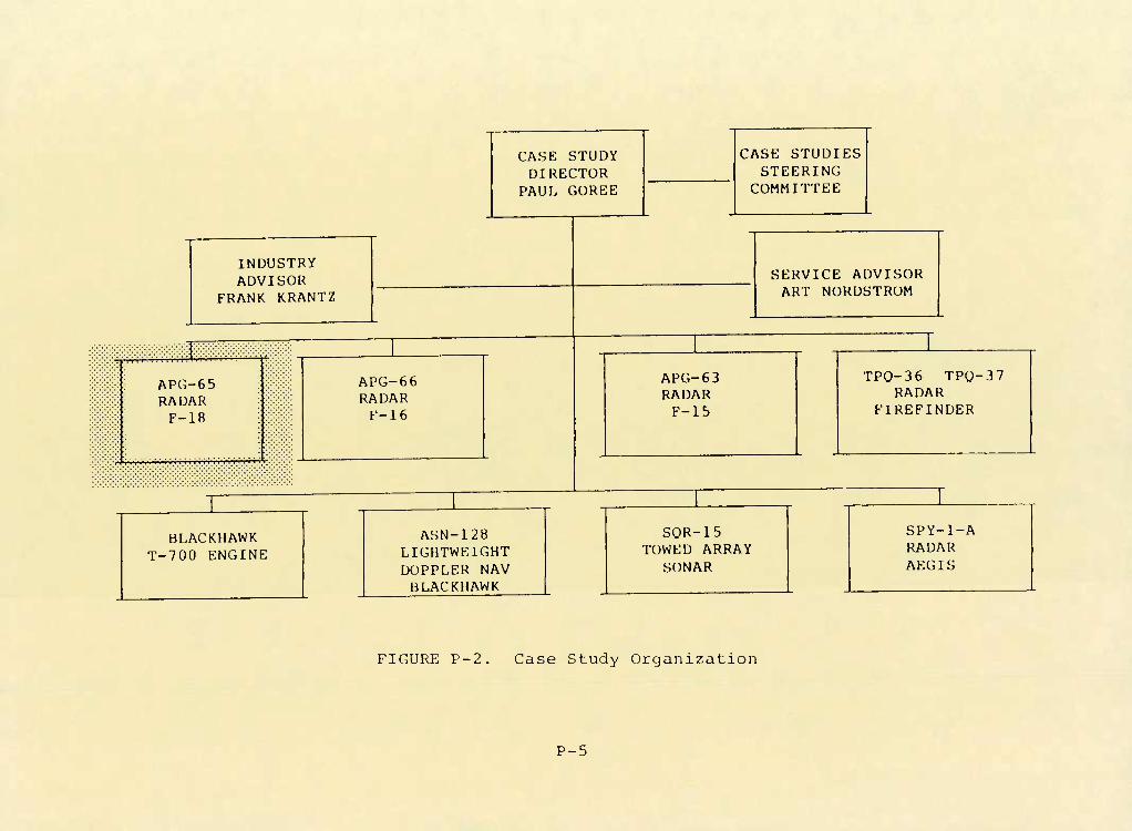
case studies, the organization shown in Fig. P-2 was established.
In some areas where program documentation and records did not exist, the actual
experience and judgement of those involved in the programs were captured in the case
studies. Likewise, in the analysis process, the broad base of experience and judge-
ment of the military/industry executive council members and other participants was
vital to understanding and analyzing areas where specific detailed data were lacking.
This document records the program activities, details and findings of the Case
Study Working Group for the specific program as indicated in Fig. P-2.
Without the detailed efforts, energies, patience and candidness of those inti-
mately involved in the programs studied, this case study effort would not have been
possible within the time and resources available.
The views expressed within this document are those of the working group only.
Publication of this document does not indicate endorsement by IDA, its staff, or
its sponsoring agencies.
P-4
CASE STUDY DIRECTOR
PAUL GOREE
CASE STUDIES STEERING
COMMITTEE
INDUSTRY ADVISOR
FRANK KRANTZ
m APG-65 RADAR
F-18
APG-66 RADAR
F-16
SERVICE ADVISOR ART NORDSTROM
APG-63 RADAR F-15
TPO-36 TPO-37 RADAR
FIREFINDER
BLACKHAWK T-700 ENGINE
ASN-128 LIGHTWEIGHT DOPPLER NAV BLACKHAWK
SOR-15 TOWED ARRAY
SONAR
SPY-l-A RADAR AEGIS
FIGURE P-2. Case Study Organization
P-5

F/A-18 AN/APG-65 RADAR
RFLIARILITY AND MAINTAINABILITY CASE STimV

F/A-18 APG-B^ RADAR WORKING GROUP PARTICIPANTS
MCAIR
£.W. BAILEY
G. FISHER
W. LAUDEL
W.R. ROGGER
J. SLINKARU
E. TOU
SUBSYSTEM MANAGER. F-18 RADAR/ATTACK SENSORS
SECTION MANAGER. F-18 MAINTAINABILITY
CHIEF ELECTRONICS ENGINEER
SECTION CHIEF. F-18 RELIABILITY
TECHNICAL SPECIALIST. F-18 MAINTAINABILITY
SECTION CHIEF. F-18 RADAR
HUGHES
C.F. FARRELL F-18 RADAR. RELIABILITY AND QUALITY
F.B. NELSON F-18 RADAR PROGRAM MANAGER
IDA
P.S. GIBSON
G-A. KUNZNICK
T.A. MUSSON
OSD/MRA&L
IDA CONSULTANT
IDA CONSULTANT
4bA/2 11

CASb STUUY UUlLINh
^b/i-1
• INTKOUUCTIUN 1
- MISSION NLtUS 2
- SYSTEM DESCRIPTIUN 16
- PROGRAM SUMMARY 32
- MEASURES OF SUCCESS 52
• PROGRAM ELEMENTS 65
- CONTRACT 65
- MANAGEMENI 103
- DESIGN 121
- MANUFACTURING 191
- TEST AND EVALUATION 221
• SUMMARY AND LESSONS LEARNED 267
111

R&M PROGRAM REVIEW ELEMENTS
CONTRACT 1. R&M Requirements 2. Mission Profile Establishment 3. Life Profile Establishment 4. RsM Failure Definition 5. Incentives 6. Source Selection Criteria 7. LCC Consideration
MANAGEMENT 8. Planning Control & Emphasis 9. Monitor/Control of Subcontractors &
Suppliers
DESIGN 10. Development of Design Requirements 11. Design Alternative Studies 12. Design Evaluation Analysis 13. Parts St Material Selection & Control 14. Derating Criteria 15. Thermal & Packaging Criteria 16. Computer Aided Design 17. Testability Analysis 18. BIT and ATE Performance 19. Features to Facilitate Maintenance
MANUFACTURING 20. ~ - ESS of Parts/Equipment 21. Failure Analysis/Corrective Action
TEST & EVALUATION 22. Design Limit Qualification Testing 23. Reliability Growth Testing 24. Demonstration Testing 25. Operational Test and Evaluation 26. Inservice Assessment
38/51-1 IV

ARRRKVIATIONS F-18
ACM A/D AFTA AGR ANT APU
BIT
CCM CDR CFE CLEAR
CMOS
CW CWI
D D&T DBSP DRRS DIP
DLI DMMH/FH
p]AROM
ECL KCM ECP ECS EM EMI EMP Esn
Air Combat Maneuver AnalogtoDigital Avionics Fault Tree Analyzer Air-to-Ground Range Antenna Auxiliary Power Unit
Built-in-Test
Counter Countermeasures Critical Design Review Contractor Furnished Equipment Closed Loop Evaluation and Report- i ng Complementary Metal Oxide Semicon- ductor Continuous Wave Continuo<js Wave Illuminator
Data Design and Test Doppler Beam Sharpening Patch Doppler Ream Sharpening Sector Dual-In-Line Integrated Circuit Package Deck-Launched Intercept Direct Maintenance Man Hours/ Flight Hour
Flectronically Alterable Read Only Memory Emitter Coupled Logic Electronic Countermeasure Engineering Change Proposal Environmental Control System Engineering Model Electromagnetic Interference Electromagnetic Pulse Electrostatic Sensitive Device
FBT FH FMD FMEA FMR FP FPM FRB FRR FSD FSR FTT
GFE GMTI GMTT GPS GSR GTWT
HAC HOTAS
I I IF IRA IBIT IC ICAP
ILS IMS INS I/O IOC lOTsE
Field Effect Transistor Flight Hour Failure Maintenance Data Failure Mode and Effects Analysis Frequency Modulation Ranging Flatpack Failures per Mission Failure Review Board Fleet Readiness Squadron Full Scale Development Fleet Supportability Evaluation Fixed Target Track
Government Furnished Equipment Ground Moving Target Indicator Ground Moving Target Track Ground Power Switch Ground Support Equipment Gridded Traveling Wave Tube
Hughes Aircraft Company Hands on Throttle and Stick
Integrat ion Intermedi ate Intermediate Frequency Initial Bit Assessment Initiated BIT Integrated Circuit Integrated Corrective Action Program Integrated Logistic Support Information Management System Inertial Navigation Set Input/Output Initial Operating Capability Initial Operational Test and Evalu- ation

LCC Life-Cycle Cost LVPS Low Voltage Power Supply
M Maintainability MAC McDonnell Aircraft Company M/BIT Maintainability/BIT MDC McDonnell Douglas Corporation MEI Maintenance Engineering Inspection [^/IPHBF Mean Flight Hours Between Failures MFHBMA Mean Flight Hours Between Mainte-
nance Actions MHz Megahertz MMH/FH Maintenance Man Hours per Flight
Hour MMP Maintenance Monitor Panel MP Mission Profile MSI Medium Scale Integration l^^pyp Mean Time Between Failures MTBUMA Mean Time Between Unscheduled Main-
tenance Actions MTTR Mean Time to Repair
NASA National Aeronautics and Space Administration
OH/FH Operating Hour per Flight Hour OME Operational Mission Environment
PARAMP Parametric Amplifier PAX River Patuxent River Naval Air Station,
Maryland PBIT Periodic BIT PCA Physical Configuration Audit PD Pulse Doppler PDC Production Duty Cycle PDI Pulse Doppler Illuminator PDR Preliminary Design Review PRF Pulse Repetition Frequency PVU Precision Velocity Update
Q Quality QRB Quality Review Board
R Reliability R&M Reliability and Maintainability RBGM Real Beam Ground Map RCVR Receiver RDP Radar Data Processor RDT Reliability Development Test R/E Receiver/Exciter RF Radio Frequency RFI Radio Frequency Interference RSP Radar Signal Processor RWS Range While Scan
S/N Serial Number SRA Shop Replaceable Assembly SSS Sea Surface Search SST Sea Surface Targeting STT Single Target Track STTL Schottky Transistor-Transistor Logic
th Terrain Avoidance TAAF Test, Analyze, and Fix T&E Test and Evaluation TECHEVAL Technical Evaluation TTL Transistor-Transistor Logic TWS Track While Scan TWT Traveling Wave Tube TX Transmitter
VA Attack Squadron VF Fighter Squadron VFO Variable Frequency Oscillator VMFA Marine Corps Fighter Attack Squadron VS Velocity Search
WRA Weapon Replaceable Assembly
XMTR Transmitter
VI

NTRUUUCllUN
45/3-2

MTSSLON NKKHS

RADAR REQUIREMENTS
Radar reliability is to a great extent driven by the aircraft mission requirements
and the radar requirements, since these requirements determine system size, weight, power
and complexity. The major factor is a requirement for all-weather air superiority, which
determines detection range and radar missile compatibility factors. This need for longer
range head-on detection in great measure determines transmitter size and power requirements.
In addition, all-aspect, all-altitude detection determines waveform selection and complexity.
These factors led to the selection of a high/med PRE transmitter design in the F/A-18.
Detection range is also influenced to a great extent by antenna diameter and sidelobe
characteristics. In the case of the F/A-18 radar, mission requirements and aircraft design
resulted in an antenna size (antenna diameter is 26.625 inches) that did not require hydraulic
drive and a roll gimbal resulting in a more reliable direct electrical drive approach.
Another key area in determining detection range is receiver sensitivity. Historically, the
requirement for a low receiver noise figure necessitated a parametric amplifier (PARAMP).
In the case on the F/A-18, technology advancement allowed the required sensitivity to be
et with a more reliable field effect transistor (FET) approach.
AIM-7F SPARROW missile compatibility is the other major factor in determining trans-
itter power requirements. On earlier aircraft (F-4) this compatibility was provided by
the addition of a separate CW illuminator. The F-15 proved the feasibility of providing
SPARROW compatibility using the high PRE pulse doppler waveform negating the need for a
separate transmitter with its inherent reduction in system reliability. This concept has
been adopted on the F/A-18. High PRF systems typically operated at 40-50% duty factors to
meet detection range and missile requirements. The APG-65 uses range gating techniques
which provide an equivalent capability but operate at a reduced duty factor ("=33%) and
thus provide resultant increase in reliability in range while search mode.
45B/5-1
m
m

KADAR REQUIREnENTS
• SYSTEM SIZE. WEIGHT. POWER REQUIRED. AND COMPLEXITY
PRIMARILY DRIVEN BY MISSION REQUIREMENTS
• DETECTION RANGE
• POWER REQUIREMENTS/WAVEFORM
• ANTENNA DIAMETER
ELECTRIC VS. HYDRAULIC DRIVE
• RECEIVER SENSITIVITY
PAR AMP VS. FIELD EFFECT TRANSISTOR (FET)
• MISSILE COMPATIBILITY
• WAVEFORM
HIGH/MED PRF VS. MED PRE ONLY
• DUTY FACTOR IN PDI
Wl VS. 10%
45A/3-3

Air-to-ground resolution requirements on previous systems were met by "brute force"
techniques of higher frequency or larger antenna diameter. In the APG-65 case, a resolution
enhancement of 67:1 is provided by use of advanced doppler beam sharpening processing tech-
niques which tends to increase system complexity but not to the level required by brute
force techniques.
The F/A-18 requirement as a multi-mission aircraft necessitated the creation of highly
complex digital signal processing which is provided by a fully programmable signal processor,
which replaces the less reliable hard-wired machines used on previous programs. The multi-
mission requirements also result in a significant increase in computer memory size require-
ments. In the APG-65 this is provided by a 256K 16-bit word disc memory with a much higher
reliability than previous memory devices of equivalent capacity.
45B/5-2

KAUAK KmuiRbNbNTS (CONTINUED)
• KESOLUTION
• FKtyUtNLY (REAL BEAM bkUUNU hAP)
• ANTENNA UIAMEIEK (KEAL BEAh GKUUNU MAP)
• PKOCESSINI: CUMPLEXriY (UUPPEEK BEAM SHAKPENINb)
• MUEIIPEE MISSIONS
• PKUCESSING SPEEU/CUMPLEXIIY
PKOGKAMMABLE VS. HARDWIRED LUGIL
• MEMORY CAPACITY .
^b/3-4

RADAR SYSTEM EVOLUTION
The F/A-18 aircraft and APG-65 radar were designed from the start for multi-mission
capability. As a consequence the radar incorporates the latest performance features of
current fleet fighter and attack aircraft, and a number of features not previously used in
other operational systems. In the attack area the system incorporates many of the modes
used on current Navy A-7 and A-6 aircraft and adds many additional modes (such as high
resolution mapping) previously available only in special R&D programs.
In the fighter arena the APG-65 radar incorporates the main features of the radar on
the F-4J that it replaces, has a track while scan mode first incorporated on the F-14,
includes the Medium PRF waveform developed on the F-15 for all aspect capability, and adds
additional features such as the raid assessment mode not available previously.
45B/7-38

RADAR SYSTEM EVOLUTION
AT7ACX
RF-4B/APQ-99
£ A-7/APQ-116 • IMPROVED RESOLUTION
» A/G RANGING • REAL BEAM • PENETRATION MODES
A-7E/APQ-126 • ADDED FREQUENCY
AGILITY
ADVANCED WEAPON DELIVERY
MMR/FARMAR
F^B/APQ-72
A6-E/APQ-148 » IMPROVED RESOLUTION • PIXED TARGET TRACK • FREQUENCY AGILITY • PENETRATION MODE
F/A-18 RADAR FIGHTER/ATTACK
FIGHTER
F-4B/APQ-72 • PULSE RADAR • NO LOOK DOWN
F-4J/AWG-10 • ADDED PULSE DOPPLER • GOOD HEAD ON PERFORMANCE • POOR TAIL PERFORMANCE
F-14/AWG-9 • ADDED TWS • HIGHER POWER
• INCREASED HEAD-ON PERF.
i F-15/APG63 • ADDED MEDPRF • ALL ASPECT/ALL ALTITUDE
PERFORMANCE
A

RADAR SKT AIR-TO-AIR CAPABILITY
The APG-65 radar represents the latest step in pulse doppler radar development that
started with the AN/AWG-10 radar for the F-4J. The AWG-10 was the first fighter system to
use pulse doppler allowing head-on look down capability. This system retained the pulse
search mode of conventional radars and had a boresight acquisition capability. Because of
sidelobe clutter limitations, tail hemisphere look-down capability was limited. The
AWG-lOA shown is the latest version of this radar incorporating digital avionics and provides
improvements over earlier versions of the AWG-10.
The AWG-9 system features a higher power transmitter and larger antenna for greatly
enhanced head-on detection capability. This system includes a range-while-search and a
track-while-scan (TWS) mode which, when coupled with the AIM-54 missile system, provides a
multishot missile capability. To improve air combat maneuver (ACM) performance, a vertically
scanning acquisition mode was incorporated.
The APG-63 radar was developed with a digital processor which provided a breakthrough
in processing technology and allowed the development of the medium FRF waveform which, for
the first time, allowed true all-aspect, all-altitude detection capability. The APG-63
also added a HUD acquisition mode for rapid automatic acquisition of targets within the
head-up display field of view.
The F/A-18's APG-65 radar draws on all of this experience and contains a completely
programmable signal processor which, when coupled with its basic high, medium, and low PRF
transmission and receive capability and low sidelobe, narrow bandwidth antenna design,
allows the incorporation of the best features of these systems. In addition, the technology
developed for doppler beam sharpened ground mapping has been exploited to provide a unique
air-to-air raid assessment capability against closely spaced targets.
45B/2-1

RADAR SET AIR-TO-AIR CAPABILITY
ALL ASPECT LOOK-UP/LnOK-DOWN DETECTION AND TRACK
- INTERLEAVED HIGH AND MEDIUM PRFs IN RANGE WHILE SCAN (RWS) AND TRACK WHILE
SCAN (TWS) MODES
MULTIPLE TARGET TRACK IN TWS
- RADAR MAINTAINS TRACK FILE OF 10 TARGETS (8 DISPLAYED)
- TARGETS PRIORITIZED ON TIME TO GO
- AUTOMATIC CENTERING OF AZIMUTH AND ELEVATION SCAN
- STEERING AND LAUNCH PARAMETERS FOR TOP PRIORITY TARGET
RAID DETECTION
- TRACK POINT IS EVALUATED FOR MULTIPLE TARGETS IN FORMATION
ECM DETECTION
- RADAR PROVIDES ADVANCED ECM ASSESSMENT, ADVISORY AND CCM
RAPID TARGET ACQUISITION IN COMBAT
- AUTOMATIC ACQUISITION USING THREE SPECIAL SCANS - HUDACQ, VACQ AND BST
PULSE DOPPLER ILLUMINATION
- RF TARGET ILLUMINATION FOR MISSILE LAUNCH
DESIGNED FOR SINGLE PLACE OPERATION
- HANDS ON THROTTLE AND STICK (HOTAS) CONTROL
- AUTO RADAR PARAMETER SELECTION WITH WEAPON SELECTION
- UNCLUTTERED DISPLAYS
45A/9-10

Some of the key air-to-air features of the APG-65 radar include all-aspect target
detection in the presence of clutter, multiple target track with launch and steering
information displayed for the top priority target. A raid assessment mode helps to determine
if a multiple target cluster is being tracked and the advanced ECCM features provide for
operation against ECM. In a close-in combat situation, the three air combat maneuver ac-
quisition rasters provide for rapid radar lock-on. All this capability can be easily con-
trolled using the Hands on Throttle and Stick (HOTAS) control and the uncluttered displays.
45B/2-2
11

RADAR AIR-TO-GROUND MODES
The broad range of air-to-ground modes in the Hornet radar is illustrated in this
chart. The combination of coherent frequency operation and programmable digital signal
processing provides for real time azimuth doppler beam sharpening. This feature allows
the radar to have variable effective beamwidths from 3.3° to 0.05°. The digital signal
processing enables an accurate terrain avoidance mode including clearance plane deter-
mination. A sea surface targeting mode using adaptive thresholding is provided to en-
hance detection capability against surface targets such as Komar and Kynda. Coherent
frequency techniques have also made it possible to realize a GMTI/GMTT mode with excel-
lent sub-clutter visibility, more accurate air-to-ground ranging, and precise aircraft
velocity measurements to aid in navigation and weapon delivery. Aircraft velocities in
the velocity update mode are measured to within one foot per second allowing in-flight
alignment of the Inertial Navigation Set (INS) and INS updates to reduce navigation errors,
45B/3
12

AIR-TO-GROUND MODES
• REAL BEAM GROUND MAP (RBGM)
• DOPPLER BEAM SHARPENING SECTOR (DBSS)
o DOPPLER BEAM SHARPENING PATCH (DBSP)
• SEA SURFACE TARGETING (SST)
• PRECISION VELOCITY UPDATE (PVU)
o GROUND MOVING TARGET INDICATION (GMTI)
• TERRAIN AVOIDANCE (TA)
• FIXED TARGET TRACK (FTT)
• GROUND MOVING TARGET TRACK (GMTT)
• AIR-TO-GROUND RANGE (AGR)
13

MODE STATUS
AIR-TO- -AIR AIR-TO-GROUND
VS OPERATIONAL RBGM OPERATIONAL
RWS OPERATIONAL DBS SECTOR OPERATIONAL
TWS OPERATIONAL DBS PATCH OPERATIONAL
STTw/PDI OPERATIONAL PVU OPERATIONAL
ACM OPERATIONAL AGR OPERATIONAL
RAID OPERATIONAL SSS OPERATIONAL
SRT OPERATIONAL TA OPERATIONAL, NCTR PARTIAL IMPROVEMENT REQUIRED
ECCM PARTIALLY OPERATIONAL
GMTI
GMTI/RBGM
FTT
GMTT
OPERATIONAL, IMPROVEMENT REQUIRED
OPERATIONAL, FURTHER DEVELOPMENT REQUIRED OPERATIONAL OPERATIONAL, IMPROVEMENT REQUIRED
15

SYS'I'KM OKSCRIPT ION

AN/APG-6 5 RADAR SYSTEM
The APG-65 radar incorporates advanced technology to combine features into a 5 WRA
system. This reduction in number of units from 19 WRAs on the F'-14 (AWG-9), and 9 on
the F-16 (APG-63) facilitates maintainability and improves the fault isolation capability.
The five WRAs are:
Low Sidelobe Planar Array Antenna is a 26.625 inch diameter antenna with direct electric
drive. All electronic components are contained in an easily removable SRA, thus not
requiring antenna removal for most failures. Antennas can be removed and replaced
without requiring harmonization, thus reducing maintenance time.
Receiver/Rxciter—This unit combines radar receiver, radar exciter, and all analog to
digital conversion functions in a single unit.
Transmitter—The APG-65 transmitter is a liquid cooled design featuring a gridded TWT
that provides low, medium, and high PRF waveforms and missile illumination.
Radar Data Processor--This is a general purpose computer containing a memory capacity
of 256,000 16 BIT words (4 megabit) on a disc memory. This disc provides the program
storage for both the 32K data processor and the 192K signal processor operating mode
memories. This unit also contains the radar low voltage power supply.
Radar Signal Processor—This is a completely programmable special purpose processor
operating at a 7.2 MHz rate to perform complex operations. It has a 192K word operating
mode memory and contains a separate general purpose processor to allow parallel
operations.
45B/7-37
16

i|5A/3-b
AN/APG-65 RADAK SYSTEM
• FIVE WKAs
LOW SlULLUBt PLANAK AKKAY ANTENNA
RECEIVEK/EXCITEK
TKANSMiriEK
■ KAUAR DATA PROCESSOR
RADAR SIGNAE PROCESSOR
17

AN/APG-65 RADAR SYSTEM
ANTENNA
TRANSMITTER
RADAR SIGNAL PROCESSOR
19
l.tWH (US' 1
/

RADAR INSTALLATION
The APG-65 radar is installed in a vibration isolated rack configuration to protect
the radar.system from vibration created by the 20mm qun system. Due to this isolation
design the radar remains at a relatively benign vibration level even during gunfire opera-
tions. This rack design also allows for easy maintenance. The radome swings to the side
and the entire radar package can be rolled forward, allowing access to all WRA's from one
side of the aircraft. The rack also contains an inherent gun gas and EMI shield to protect
the radar WRA's from associated environmental factors. Electrical and cooling services are
provided via a pantograph assembly allowing radar operation with the nose rack in extended
pos it ion.
45B/8-15
20

GENERAL;
VOLUME:
WEIGHT:
RADAR INSTALLATION
COMPATIBLE WITH REYOND VISUAL RANGE AIM-7F MISSILE. SHORT RANGE AIM-9 AND GUN DIRECTOR MODE OPERATING RANGES FROM 200 FT. TO 160 NMI. MULTI-WAVEFORM - FREQUENCY AGILE FULL COMPLEMENT AIR/AIR AND AIR/GROUND MODES WIDE AZ SCAN ±70°/WIDE ELEVATION TO 8 BARS AUTOMATIC INITIALIZATION/ONE MAN OPERABLE
i^.37 FT3
343 LB (EXCLUDES RACK)
GUN MUZZLE SUPPORT
RELIABILITY: 106 HOUR DEMONSTRATED MTRF (MIL-STD-781B)
MAINTAINABILITY DEMONSTRATED 11-6 MIN FLIGHTLINE MTTR
PARTS: 13.i|67
POWER; 9.500 WATTS
COOLING: AIR 2.782 WATTS LIQUID 4.845 WATTS
KEY INSTALLATION ENVIRONMENTAL COONSIDERATIONS:
RADAR PACKAGE (WITH INTEGRAL GUN GAS SEAL) AMMO DRUM
PROXIMITY TO GUN (VIBRATION) GUN GAS ENVIRONMENT CARRIER LANDING
45A/4 21
/^

APG-6 5 RADAR SYSTEM PARAMETERS
The radar system consists of 5 weapon replaceable assemblies (WRA) and an isolation
rack. The transmitter is liquid cooled and the other four units are cooled by forced air.
The programmable radar signal processor contains the highest parts count and greatest heat
dissipation and accordingly has the lowest MTBF allocation.
22 45B/8-16

APG-65 RADAR SYSTEM PARAMETERS
MTBF
WEIGHT VOLUME ALLO- PRE- (LBS) (FT3) GATED DICTED
PARTS SUMMARY
DISSIPATION (WATTS)
OTHER TOTAL AIR LIQUID ICs ELECT PARTS COOLED COOLED
ANTENNA 84.2 N/A 700 1370 57 362 429 167
TRANSMITTER 113-2 2-05 700 1130 154 1703 1857 4845
RCVR/EXCITER 45.9 .91 800 1110 49 1358 1407* 387.2
RADAR SIGNAL 55-0 .91 300 PROCESSOR
427 3964 2652 6616 1599.3
RADAR DATA 44-5 PROCESSOR
.91 600 835 1089 2224 3133 628.7
RACK 109.4 4400 24500 34 34
SYSTEM TOTAL 452.2 4.37 106 164 5325 8142 13467 2782 4845
•49 HYBRIDS
45A/3-5 23

MEMORY
The F-18 APG-65 radar contains more computer memory than any other current production
fighter radar. This is due, in part, to the numerouc radar modes and to the large storage
requirements of the multi-mode programmable signal processor.
45B/8-15A
24

MEMORY LOADING
RSP
CONSTANTS ORDERS WORDS
A/A 6.896 16,786 60,702 A/G 2,164 14,961 48,129 BIT 252 3,936 12,336 EXEC/LOADER 0 562 1,686 FFT 1,024 0 1,536
TOTAL 10,336 36,245 124,389
RDP A/A 21,430 30,002 A/G 16,938 23,712 BIT 12,097 16,935 COMMON 5,075 7,104
TOTAL 55,540 77,753
DISC RSP 36,245 124,389 RDP 55,540 77,753 FLIGHT TEST 4,000 SPARES 4,300
TOTAL 91,785 210,442
5-3-83 25

MAJOR F-18 PROGRAM EMPHASIS
Reliability and maintainability were given equal program emphasis with performance and
cost. The Navy offered MCAIR Life-Cycle-Cost incentives totaling 15 million dollars. A
total of $24 million was available for R&M incentives. MCAIR was permitted to offer R&M
incentives to major subcontractors and make those awards an allowable contract cost.
R&M was elevated in program emphasis and the entire system was optimized for a proper
balance.
26 45B/7-14

45C/1-4
MAJUK h-18 PKUGRAM LMPHASIS
EQUAL WtlGHT
K M PERFORMANCt $
• PERPURMANCb IS UtPINLU HY CUNIRACT SPtCIPICATlUNS
(AS-1291. SD-bbb-1)
• LIFE CYCLE UESIGN-TO-CUST INCENTIVE
• KELIABILITY/MAINTAINABILIIY INCENTIVE
OPUMIZE PUR BESl BALANCE
27

RADAR RELIABILITY/IJAINTAINABILITY FEATURES
'^5/3-8
"RELIAHILITY-RY-nESIGN" REQUIREMENTS IN CONTRACT INCORPORATE "ELEMENT WORST
CASE ANALYSIS"
SUBCONTRACTORS/BIDDERS KNEW MCAIR AND NAVY WERE SERIOUS AND WERE CONTINUALLY
REMINDED DURING TECHNICAL COORDINATION MEETINGS. DESIGN REVIEWS. AND SPECIAL
"AWARENESS" PRESENTATIONS
RELIABILITY/MAINTAINABILITY DESIGN GUIDELINES WERE IMPLEMENTED BY MCAIR AND
HUGHES
RADAR ANALOG PROCESSING REPLACED BY DIGITAL PROCESSING
ELECTRICAL RADAR ANTENNA DRIVE IN LIEU OF HYDRAULIC DRIVE
IMPOSED ONE DESIGN AND TEST ON RADAR
REVISED ECS COOLING AIR SCHEDULE - LOWER PART OPERATING TEMPERATURES
ADDED COOLING AIR OVERHEAT SENSORS TO PROTECT AGAINST TEMPERATURE OVERSTRESS
EXTENSIVE USE OF LOW POWER PARTS (CMOS. SCHOTTKY) TO MINIMIZE HEAT RISE
EXTENSIVE USE OF HYBRIDS. MSI. MICROPROCESSORS TO REDUCE PARTS COUNT
STRINGENT PART DERATING REQUIREMENTS SPECIFIED IN PROCUREMENT SPECIFICATION
COOLING AIR DIRECTED DOWN CENTER OF PCR FOR MINIMUM HEAT RISE AND MUCH LOWER
JUNCTION TEMPERATURES
29

APG-65 MAINTAINABILITY PROGRAM FEATURES
A MCAIR maintainability engineer was assigned to the radar system and reported directly
to the radar subsystem manager. The maintainability requirements for the aircraft installa-
tion and radar set were established via the maintainability design baseline document.
These requirements were coordinated and approved by both the subsystem manager and equipment
installation engineering. This document also serves as the basic document to initiate the
in-house ILS process. The specific maintainability requirements, both qualitative and
quantitative, were incorporated into the procurement specification which was the basic
requirement for competitive procurement.
An incentive program was included as part of the radar subcontract to allow the supplier
to receive a maintainability award which is based on measured field performance. In order
to meet the maintainability requirements, built-in-test played a major role in the design
of the radar.
A single point contact for maintainability was required at Hughes to provide a direct
link between Hughes design engineering and MCAIR maintainability.
45B/7-13 -^^

MAINTAINABILITY PKOGKAM FEATURES
• MAINTAINABILITY RESPONSIBILITY ASSIGNED TO SUBSYSTEM
MANAGERS
• MAINTAINABILITY CLOSELY TIED 10 ILS
• MAINIAINABIEIIY DESIGN BASELINE ESlABLlSHED
REOUIREMENIS/GOALS
» MAINIAINABIEIIY iNVOEVEMENI IN SUBCONTRACIING
• flAINTAINABILIlY REOUIREMENTS UUANl IKIED
• MAINTAINABILIIY INCENTIVES
• MAINTAINABILIIY ON A PAR WITH PERFORMANCE
• MAINIAINABIEIIY INVOLVEMENT IN BIT PROGRAM
MAINIAINABIEIIY SINGLE POINl OF CONlACI Al CUSTOMER
4b/T3-3 31

PR(>C,kA'1 SIIMMAl^Y

APG-65 PROGRAM SUMMARY
Early in the program, the radar supplier, Hughes, was convinced that MCAIR was serious
about R&M. This conviction was partially based upon the decisions that were made on the
results of radar trade studies. This feeling was reinforced with contract financial
incentives tied to challenging but achievable R&M requirements. Subsystem managers and
individual designers were made personally responsible for reliability, maintainability,
performance and cost parameters both at Hughes and MCAIR. These parameters were treated
with equal emphasis in trade studies and design reviews. Technology was continuously
monitored for potential reliability benefits and also for new threats such as ESD and EMP.
Concurrency in testing extended the growth available through TAAF efforts. The F-18 pilot
production concept allowed for rapid corrective action. Experience indicated that change
flexibility is required for real growth in R&M.
Experience indicates that Physical Configuration Audit (PCA) should be established at
the latest reasonable date to enhance the early incorporation of design changes. Additionally,
change processing needs to be streamlined beyond PCA. Productivity programs should be
encouraged since they can provide reliability, maintainability, and cost benefits. In
selecting the right supplier, competition is an important element, and courage in selection
(in the face of cost) is critical. The Navy "New Look" R&M program structure provided the
framework for the radar program.
45B/7-36
32

APG-6b PKUGKAM SUMHAKY
45A/12-1
• R&M MOTIVATION EARLY IN THE PROGRAM
• DEFINITIVE REQUIREMENTS - CHALLENGING. BUT ACHIEVABLE
• DESIGNERS RESPONSIBLE FOR RELIABILITY. PERFORMANCE.
MAINTAINABILITY. COST
- DESIGN REVIEWS TREAT EACH WITH BALANCED EMPHASIS
• MONITOR TECHNOLOGY FOR PROGRESS AND NEW THREATS TO R&M
- ESD/EMP
• CONCURRENCY PROVIDES BENEFITS IF:
- CONTRACTOR SUPPORT FOR INITIAL FIELD INTRODUCTION IS
PROVIDED
- EXTEND THE GROWTH ACHIEVABLE THROUGH TAAF EFFORTS
33

APG-6b PKUbRAM SUhhAKY (CONTINUED)
• GKUWTH IN K&n UbMANUS CHANGE FLhXlBILITY
- PILUT PKUUUCIIUN CUNCbPT ALLOWS RAPID CURKLCllVL
ACTIONS
- LSIABLISH PHYSICAL CONFIGURAlION AUDIT (PCA)
POINTS AT LAIEST REASONABLE POINT
- SIREANLINE ECP PROCESSING
• PRODUCTIVITY PROGRAMS SHOULD BE ENCOURAGED
- COST AND R&M BENEEITS
• SELECT IHE RIGHT SUPPLIER
- COURAGE IN THE SELECIION PROCESS (IN THE PACE
OF COST)
- COMPLlITION IS INPORTANI
• NAVY R&M PROGRAM - NEW LOOK - PROVIDES IHE FRAMEWORK
4bA/T2-2 35

AIRFRAME SYSTEM R&M FEATURES TO IMPROVE RADAR AVAILABILITY
In previous aircraft designs, inadequate safeguards in the design allowed the radar to
be operated on the ground without cooling air, due to lack of ground cooling carts or
improper maintenance. This resulted in overheating of the equipment, causing premature
failures. On-board cooling fans were incorporated in the F-18 to eliminate this potential
problem from the F-18 design.
A requirement was imposed on MCAIR to demonstrate a 20.0 minute radar remove and replace
time with a crew size of 1.8. During the maintenance engineering inspection conducted in
February 1980, a 11.6 minute remove and replace time was demonstrated with a crew size of
1.5.
Maximum use of BIT for the radar, coupled with modular construction reduced the need
for ground support equipment and handling fixtures at the organizational level. These
features decrease the down time required for radar maintenance and improve radar availability.
Ground power switching, which was first incorporated on the F-15 radar, was carried over
to the F-18 radar. This allowed the maintenance man to select the systems to power up during
maintenance, thus eliminating excessive operating time on the radar and improving the mean
flight hours between failure.
45B/7-27
36

AIRFRANE SYSTEM R&fl FEATURES TO IMPROVE RADAR AVAILABILITY
45A/3-7
• GROUND COOLING FANS PROVIDE AIR FLOW IMMEDIATELY ON POWER UP
- HISTORICALLY. GROUND COOLING CARTS ARE AVOIDED BY MAINTE-
NANCE PERSONNEL, RESULTING IN THERMAL STRESS ON EQUIPMENTS
- GROUND FANS PROVIDE NECESSARY AIR FLOW FOR MOST MAINTE-
NANCE WITHOUT GROUND CARTS
• AIRCRAFT INSTALLATION ALLOWS QUICK REMOVAL AND REPLACEMENT OF
RADAR WRAs
• EXTENSIVE USE OF BUILT-IN-TEST MINIMIZES TROUBLESHOOTING
TIMES (NO GROUND SUPPORT EQUIPMENT)
• GROUND POWER SWITCHING ALLOWS SELECTIVE GROUND OPERATION -
ELIMINATES UNNECESSARY RUN TIME
37

GROUND POWER SWITCHING
One design objective on the F-18 was to minimize the operating time of the avionics.
The less ground operating time per flight hour of the aircraft, the fewer failures per
flight will be experienced. Reduction of ground operating time was achieved through
effective BIT rapidly isolating to WRAs and through ground power switching (GPS). GPS is
mechanized such that on initial a/c power turn-on, all avionics are off. Manual switch
positioning is required for any avionic operation. The selective switching eliminates
unnecessary radar operation during checkout of other avionics.
The reduction of operating hours per flight hour (OH/FH) results in fewer failures for
a given number of flights or flight hours.
45B/7-18
38
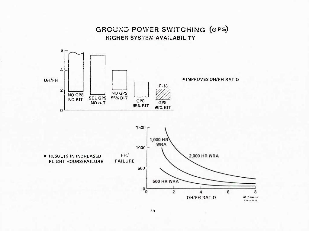
GRCUXD POWER SWITCHING (GPS)
HIGHER SYSTE.V* AVAILABILITY
OH/FH
0
NO GPS IMOGPS NO BIT SELGPS 95% BIT -—
NO BIT '^^^
F-18
W/ GPS
95% BIT ggo/^ Bij
IMPROVES OH/FH RATIO
1500 r
1000 -
• RESULTS IN INCREASED ^H/ FLIGHT HOURS/FAILURE FAILURE
500 -
OH/FH RATIO
39

R&M GROWTH
• R&M REVIEW BOARD DURING DEVELOPMENT
• DEVELOPMENTAL TEST. ANALYZE AND FIX
• R&M MONITORING DURING INITIAL TRAINING SQUADRON USE
• SPECIAL BIT MONITORING TEAM
• CONTRACTOR SUPPORT OF INITIAL INTRODUCTION PHASES CRITICAL
. FOR FEEDBACK TO SUSTAIN R&M GROWTH
• SUPPLIER PROCEDURES FOR COORDINATION/EVALUATION OF DATA FROM
ALL MANUFACTURING SOURCES - INITIAL PARTS SCREEN TO FINAL
ACCEPTANCE
• INTEGRATED CORRECTIVE ACTION PROGRAMS (ICAP)
- FIELD/MCAIR/SUPPLIER COORDINATION POINT
• MAXIMUM GROWTH - KEEP INITIAL APPLICATIONS COMPATIBLE WITH
CONFIGURATION CHANGES
45A/15-20 41

PROGRAM ELEMENTS
The APG-65 radar program was structured to test and evaluate those elements that
constituted the largest design/reliability risk early in the program. Special element
development tests were performed on the disc memory and GTWT during 1977. The first
engineering models entered testing in late 1977. Lab and environmental testing and
reliability development testing were structured to test areas of high potential risk early,
A 1/2 life vibration test and exposure to gunfire vibration testing were performed early
in the test program. Temperature cycling to the extreme temperature environments was also
performed early to ensure no latent design defects were present.
45B/8-17
42

PROGRAM ELEMENTS
1975 1976
PROPOSALS/TRADES/ SELECTION
RADAR GO AHEAD (AUG 76) (PSD)
ENGINEERING MODEL RADARS
SPECIAL ELEMENT TESTS (GTWT/DISC)
FSD RADARS
SYSTEM TEST (LAB AND ENVIRONMENTAL EXPOSURE)
INITIAL BIT ASSESSMENT
RELIABILITY DEV. TEST
T-39 FLIGHT TEST
F/A-18 FLIGHT TEST
RELIABILITY FLIGHT . DEMO
PRODUCTION RADARS (MAR 80)
RELIABILITY DEMO TEST
MAINTAINABILITY DEMO TEST
45C/1-10
1977 I 1978 1979
14 TOTAL
1980
EMI
1981 1982
ENV
v=v
v=================== HAC-94 MCAIR-150 ! 1
V================
PILOT PROD S/N 15
1983
•P^B
43

PROGRAM ELEMENTS
The APG-65 radar program began in 1975 with proposals being considered from seven
radar contractors. In early 1976, Hughes Aircraft and a team consisting of Westinghouse
and Norden were chosen as finalists. In August of 1976 the Hughes Aircraft design was
selected. Testing began on key elements (gridded traveling wave tube, disc memory, etc.)
in early 1977 and system level testing on engineering models (EM) began in late 1977.
Design of these (EM ' s) was started prior to contractor go-ahead as part of the Hughes head-
start program. Flight testing of an EM radar began in March of 1978 using a modified T-39D
radar test bed. In August of 1978, the first of 14 full-scale development (FSD) radars
began flight development, which continued until mid-1982 on both the T-39 and F-18 aircraft.
Key reliability milestones include reliability development testing, starting in
September, 1979, and 50 flight (100 hour) aircraft reliability demonstration in October,
1980 which was completed with no radar failures and the 106-hour radar reliability demo which
was completed in January 1983. During this test, 2 radars were run for a total of 149
hours to a MIL-STD-781 environment with no radar failures.
45B/8-18
45

NAVY FLIGHT AND SUPPORT TfclST KLKMKNTS
:em
During the radar development phase, a number of assessments and evaluations were
conducted. During these tests. Navy pilots and maintenance personnel evaluated syst
performing reliability and maintainability aspects of the radar. Comments written by Navy
personnel were then submitted to MCAIR/Huyhes tor possible incorporation in design changes
and reevaluated during subsequent exercises. While some R&M improvements were incorporated
as the result of the exercises, the several conclusions were that the radar met all R&M
criteria at each stage of the assessment.
46

NAVY FLIGHT AND SUPPORT TEST ELEMENTS
NAVY PRELIMINARY ASSESSMENTS T-39 OCT 1978 JUL 1979
NAVY PRELIMINARY EVALUATION F7A-18 OCT 1979 MAR 1980 OCT 1980
NAVY PARTICIPATION FLIGHTS: F/A-18 MAR 1980 - 28 JAN 1981
lOTiiE (INiriAL OPERATIONAL TEST AND EVALUATION)
F/A-18 11 OCT 1980 - 28 JAN 1981
NAVY TECHEVAL: F/A-18 MAR 1982
OPEVAL F/A-18 3 MAY - 4 OCT 1982 1628 FLIGHT HOURS OPERATIONAL EMPLOYMENT
RESULT: R&M MEl ALL CRITERIA
4bA/13-19 47

F-18 RADAR RELIABILITY AND MAINTAINABILITY EVENTS
GTWT AND DISC TESTING
REL GROWTH TEST
EMI
ENVIRONHENTAL QUAL
INITIAL BIT ASSESSMENT
REL QIIAL TEST #1 WAIVED
#2
50 REL DEMO FLIGHTS 5-19 NOV 80
1976 ! 1977.1 1978 I 1979 I 1980 I 1981 ! 1982 I 1983
3 (SHARED)
TS
9 6 IITS 1=======^===!
1=====!
__ I 11 I I I I
12 1 I — I
M DEMO (PLANNED)
START EM RADARS JAN 76 A
60 AHEAD (FSD) AUG 76 A
1DR OCT 76
CDR (AVIONICS) JUN 77 A
FIRST T-39 EM MAR 78
FIRST T-39 FSD AUG 78
FIRST F-18 JUN 79
PCA (S/N 27) JUN 81
PROD GO-AHEAD MAR 79 (S/N 27)
1ST PROD DELIV. JUN 81 (S/N 27)
1ST PROD FLT JUL 81 (S/N 27) IN F-17
1ST PROD FLT AUG 82 (S/N 55 1ST FLEE
PRE-PROD TT^TFTTT" PILOT PROD 11 (15-25) LIMITED PROD 29 (26*-55) *S/N 26 GSE"C]TECKOUT AT HAC!
'EM = ENGR MODEL ' S/N = SET NUMBER A/C = AIRCRAFT NO IDR = INITIAL DESIGN REVIEW!
45/13-18 49

DEVELOPMhlNTAL RADAR ALLOCATION
Originally, 16 full-scale development radars were requested. However, to reduce program's
cost, this number was reduced to 14, In addition, the equivalent of about 2-1/2 additional
engineering model radars were manufactured. Of the 14 FSD units, systems #5, #6, and #12
were allocated to reliability development and environmental test.
45B/8-20 50

DEVELOPMENT RADAK ALLOCATION
INITIAL FINAL
SET ALLOCATION SET
1
ALLOCATION
1 SELLER BENCH TESTBED
2 TtSTBED 2 SELLER BENCH
3 MCAIR BENCH 5 MCAIR BENCH
- WRA SPARES - WRA SPARES
4 ENVIRONMENTAL TEST 4 SHIP 5 (F-5)
5 ENVIRONMENTAL TEST 5 RELIABILITY DEVELOPMENT TEST
6 RELIABILITY DEVELOPMENT TEST 5 ENVIRONMENTAL TEST
7 RELIABILITY DEVELOPMENT TEST 7 PAX BENCH
8 MCAIR DATA 8 SHIP 3 (F-3)
9 SHIP 3 (F-3) 9 SHIP 7 (TF-1)
10 SHIP 5 (TF-1) ID SHIP 8 (F-7)
11 PAX BENCH 11 FLIGHT TEST SUPPORT
12 FLIGHT TEST SUPPORT 12 ENVIRONMENTAL TEST
13 SHIP 8 (F-7) 13 SHIP 10 (TF-2)
14 FLIGHT TEST SUPPORT W SHIP 11 (F-9)
IS SHIP 10 (TF-2)
16 SHIP 11 (F-9) 51
45A/13-18

MKASllRI'^S OK SllCCKSS

APG-65 RADAR RELIABILITY SUCCESS
The chart shows three of the notable milestones for the F/A-18 radar. The MIL-STD-
781B reliability demonstration test had no failures in 149 operating hours (during that
time there were no WRA removals or repairs).
52 45B/7-15

i|5A/8-13
• MdVFI^BFR 1980
100 FLIGHT HOUR nPI^ONSTKATION IN A/C F-q AT PAX RIVFI
- m RAHAR FAIIJIRFS
• JANUARY 1983 ;
FORMAL RFLIARILITY PFMONSTRATION (,MIL-STn-781 H)
- 106 HOUR MTHF HFMONSTRATFO
• SFPTFMBFR 1982 - FFHRIIARY 1983 (RFFFR TO PAGF 263)
FLFFT AVFRAGF
- 'I?7S HRS ACCMMIILATFll ' ' - '
- MTHF '2M HOURS
53

F-18 RELIABILITY DEMONSTRATED IN FLIGHT (NOVEMBER 1980)
F/A-18 Number 9 flew the 50 Reliability Demonstration flights in 100.5 flight hours
between 5 and 19 November 1980 at Patuxent River. During this period, equipment failures
and aircraft mission reliability performance were monitored by MCAIR and Navy personnel.
Aircraft 9 is the final F/A-18 FSD aircraft and represented the configuration closest to
the production article with systems improvements incorporated consistent with cost and
schedule constraints. All flights were flown by MCAIR pilots and followed air-to-ground,
air-to-air or ferry/familiarization profiles. The demonstration was performed at the
highest fly rate possible within the constraints of pilot availability and Navy support.
Of the 50 flights, the first 20 were dedicated to an air-to-ground profile, the second 20
to an air-to-air profile, and the last 10 to a ferry/familiarization profile. The air-to-
ground and air-to-air profiles incorporated simulated combat segments near the middle of
the mission and the ferry/familiarization flights incorporated a NAVAID penetration, GCA
pattern, and two touch-and-gos. During two air-to-ground flights, live gunfire and bomb
drops with MK-82SE inert bombs were performed on a practice target. Life gunfire was also
performed on two air-to-air flights.
At the completion of the 50 flights, all aircraft maintenance data were reviewed by a
joint Navy/MCAIR Review Board. During the demonstration, nine Contractor Furnished Equip-
ment (CFE) and three Government Furnished Equipment (GFE) failures occurred. These failures
are as follows: CFE—Left Wing Outboard Fuel Probe; Hydraulic Line, Right AMAD Bay; Broken
Wire, Right Fire Detection System; Clogged Hydraulic Filter; Maintenance Signal Data
Recorder; Cockpit Cooling Fan; INS; Left Trailing Edge Flap Actuator; Stores Management Set
Decoder Station 4; GFE—Left Engine (A/B Pump and Line Leak); AIM-9 Launcher Nitrogen Leak;
Right Engine Slow Start.
45B/7-4
54

•
^5A/ll-3
F-18 KELIABILITY DEMUNSTKATbD IN FLIGHT (NUVHMHER 198n)
FLEW 50 FLIGHTS USING AIRCRAFT F-9 - 100 FLIGHT HOURS IN 15 DAYS
- 20 AIR-TO-AIR. 20 AIR-TO-GROUND. 10 FLRRY FLIGHTS
- DROPPED BOMBS ON 2 FLIGHTS AND FIRED-OUT GUN ON 4 FLIGHTS
- NAVY CREWS MONITORED ALL GROUND AND FLIGHT OPERATIONS
• RELIABILITY DEMONSTRATED
- 5 FLIGHTS PER AIRCRAFT PER DAY ON 3 OCCASIONS
- FLEW 25 CONSECUTIVE TOTAL AIRCRAFT FAILURE-FREE FLIGHT HOURS
- RADAR OPERATED WITHOUT FAILURE THE ENTIRE TEST (100 FLIGHT
HOURS)
- AIRCRAFT REUUIREMENT 3-/ MFHBF
DEMONSTRATED 8-4 MFHBF
- DEMONSTRATED AIRCRAFT PROBABILITY OF MISSION SUCCESS = 0-96
(ONLY 2 MISSION FAILURES - NONE WERE RADAR)
• NAVY PILOTS FLEW TWO FLIGHTS AT CLOSE OF 50 FLIGHT DEMO TO VERIFY
AIRCRAFT STATUS - ALL SYSTEMS UP
55

F-18 AIRCRAFT 3M ANALYSIS
An analysis was made in an attempt to correlate field measurements being made by MCAIR
to reported 3M data. The analysis revealed that approximately 54% of the events that 3M
classified as failures in the MFHBF computation were classified as inherent failures by
MCAIR. Major areas of difference as interpreted by MCAIR occurred as a result of MCAIR
team follow-up in determining secondary failures, and externally induced failures.
45B/8-1
56

F-18 AIRCRAFT 3M ANALYSIS
^^l\/li-2
MAINTENANCE EVENTS % OF T01AL EVENTS
INHERENT FAILURES S4.'4
UNUUCUMENTLI) SECUNIJARY FAILURES 12-8
UNDOCUMENTED INDUCED FAILURES 16-8
NON-P.RODUCTION CORRECTED 9-6
DUPLICATE COUNT t).8
MISDOCUMENTED SUPPORT ACTION __04)
100 %
DATA FROM FEBRUARY 1981 THROUGH ^1 MAY 198Z
ALL LEMOORE AIRCRAFT
57
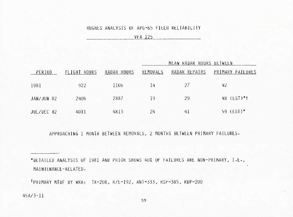
HUGHtS ANALYSIS Uh APG-bb FILLIJ KtLlABILllY
VHA 123
fl£AN KADAK HUUKS bblWhliN
PERIOD FLIGHT HOURS RADAR HOURS REMOVALS RADAR REPAIRS PRIMARY FAILURES
1981 922 110b 14 11 42
JAN/JUN 82 2406 2887 19 29 48 (EST)*r
JUL/DEC 82 4011 4813 24 41 b9 (LSD*
APPROACHING 1 MONTH BETWEEN REMOVALS. 2 MONTHS BETWEEN PRIMARY FAILURES-
'DETAILED ANALYSIS OF 1981 AND PRIOR SHOWS 40% OF FAILURES ARE NON-PRIMARY, I.E..
MAINTENANCE-RELATED.
^PRIMARY MTBF BY WRA: TX=208. K/E=192. ANT=333. RSP=385. RDP=200
45A/3-11 59

F/A-18 YUMA DEPLOYMENT
The Navy has been and is continuing to conduct a series of F-18 deployments to remote
sites. These deployments involve intensive flying schedules of both air-to-air and air-to-
ground missions. The most recent deployment at this writing was January 1983. A MCAIR
field team was in place at Yuma, Arizona, to monitor nine of the deployed eighteen aircraft
for R&M. The F-18 radar exhibited high reliability with 96% of 300 flights requiring no
radar removals. Only one of the WRAs returned to NAS Lemoore for I level repair retested
good.
45B/8-2 ^°

F/A-18 YUMA DEPLOYMENT
45A/3-9
• MOST RECENT OF MANY NAVY DEPLOYMENTS SIMULATING
OPERATIONAL UTILIZAIION
• 4 JANUARY TO 28 JANUARY 1983 "
- TRAINING SQUADRON DEPLOYMENT TO YUMA
- 18 AIRCRAFT. 613 FLIGHTS. 650 FLIGHT HOURS
- 9 AIRCRAFT WERE R&M MONITORED (~300 FLIGHTS)
• 3 OF THE 9 AIRCRAFT. 78 FLIGHTS. 83-2 FLIGHT
HOURS REQUIRED NO RADAR MAINTENANCE ACTIONS
• 96% OF FLIGHTS HAD NO RADAR REMOVALS
- 1 WRA RETURNED FOR I LEVEL MAINTENANCE WAS
RETESTED-OK. THIS WAS A MEASURED 300 SORTIES
PER UNNECESSARY REMOVAL
61

RADAR BIT DEVELOPMENT STATUS
The built-in-test software program (Tape lOlB) was released for field use in October,
1982. This program was essentially complete at time of issue. Subsequent to tape release,
areas were uncovered in which program refinement was required. These changes are currently
being flight evaluated and will be incorporated in the next scheduled program release.
The software program in the F-18 radar consists of about 30,000 16-BIT words and
performs 106 separate tests during periodic BIT (present mode) and 321 tests during initiated
BIT in which the entire radar is exercised either by pilot action or automatically when the
system is turned on.
45B/8-22
62

RAIJAK BIT DEVhLUPMENI STATUS
RAUAR BIT DbVELUPMENT UbVELOPMENT ESSENTIALLY CUMPLETE WITH TAPE lOlB
PEKIUUIL BIT lUb TESIS
INITIATED BIT 321 TESTS
43/3-12 63

PROGRAM RKVEKW Kl.KMr-lN'I'S
CUNIKACI
• Un RLQDIKbMtNlS
• Mi SSI UN PKUHLh l:.S lAHL 1 SHhLN
• R&f\ hAlLDKb IJLI-lNl I lUf
• INl-tNllVLS
• SUUKLt StLKLIlUN
• LCC CUNSIULKAIlUf
4b/3-15 §5

BASIC CONTRACT ELEMBNTS
The contract for the F-18 radar addressed reliability and maintainability in the
following ways:
a. The instruction for proposal preparation emphasized the part that would be played
by the reliability/maintainability program in the supplier selection process.
b. The equipment specification defined R&M requirements, testing, growth factors,
derating requirements, and second tier documents.
c. The purchase order contained the life cycle cost structure, design-to-cost struc-
ture, and incentives for R&M.
d. The supplier data requirements list imposed MCAIR data reporting requirements for
R&M.
e. The general management requirements included provisions for corrective action,
retrofit, test failure notification, FMEA procedure.
66 45B/7-33

APG-6b RAUAK
BASIC CONTRACT ELEMENTS
• INSTRUCTIONS FOR PROPOSAL PREPARATION
. - EMPHASIZED PART PLAYED BY RELIABILI TY/m INTA INABILITY
PROGRAM IN SELECTION
• EQUIPMENT PROCUREMENT SPECIFICAlION
- DEFINED R&M REQUIREMENTS, TESTING, GROWTH FACTORS,
DERATING REQUIREMENTS, SECOND TIER DOCUMENTS
• PURCHASE ORDER
- LIFE-CYCLE COST STRUCIURE, DESIGN-10-COST STRUCTURE,
INCENTIVES FOR R&M
• SUPPLIER DATA REQUIREMENIS LIST
- IMPOSED MCAIR DATA REPORTING REQUIREMENTS
« GENERAL MANAGEMENT REQUIREMENTS
- CORRECTIVE ACTION, RETROFIT, TEST FAILURE NOTIFICATION,
FMEA PROCEDURE
45A/9-9 67

BASIC CONTRACT ELEMENTS - SECOND TIER
The second tier of contract documents in the MCAIR/Hughes contract included a number
of documents that had direct impact on APG-65 R&M. These documents included design guidelines
processes and policy, test and evaluation standards and requirements, preferred parts lists,
and required failure reporting policy.
This list indicates the documents and their MCAIR document numbers.
45B/8-3 68

APG-bS KAUAK
BASIC CONTRACT ELEMENTS
SECOND TIER R&M DOCUMENTS
(A3807) RELIABILITY DESIGN GUIDELINES - AVIONICS
(A3374) F/A-18 PREFERRED PARTS
(A337b) OPERATIONAL MISSION ENVIRONMENT (UME) -
VIBRATION REQUIREMENTS
(A3380) SUBCONTRACTOR MAINTAINABILITY TEST STANDARDS
(A3382) TEST COMPATIBILITY DESIGN REQUIREMENTS
(A3710) MATERIALS AND PROCESSES
(A3B72) FASTENER USAGE POLICY
(A3711) CORROSION PREVENIION AND CONTROL PLAN
(A1215) PACKAGING
(A3712) NONDESTRUCTIVE TESl PLAN REQUIREMENTS
(A4150) CLOSED LOOP EVALUATION AND REPORTING
(Ail241) THERMAL DESIGN AND EVALUATION
(Ail300) RELIABILITY DEVELOPMENT TESTING
45A/I1-I m

CONTRACTUAL ASPECTS AIMED AT IMPROVED RADAR R&M
The subcontract for the APG-65 radar contained a number of features aimed at improved
radar R&M.
Design requirements for R&M included a stringent part derating requirement. This was
based on the NASA guidelines but in many instances, such as IC temperatures and transistor
power, even tougher levels were required. A detailed set of reliability design guidelines
was also utilized.
A Test-Analyze-and-Fix (TAAF) program included a reliability development test. The
TAAF philosophy was followed in all the radar testing with failure analysis and corrective
action for all failures. The emphasis on estimating MTBF from these tests was replaced
with an atmosphere of uncovering every possible weakness.
Many test requirements were placed upon the supplier: reliability development, initial
BIT assessment and maintainability BIT demonstration. During these tests each component or
test failure required analyzing and a corrective action taken. Retesting was required in
many cases.
The final test of the supplier's performance was a field measurement of the procurement
specification quantitative values. These were accomplished at 2500 and 9000 flight hours;
2500 at NATC PAX River Maryland, 9000 at NAS LeMoore California. An incentive existed for
each milestone.
45B/7-16
70

45A/3-14
CONTRACTUAL ASPECTS AlMliD AT INPKOVLU RADAR K&M
DESIGN REQUIREMENTS
• SPECIFIC DESIGN REQUIREMENTS INCLUDING DERATING CRITERIA
• RELIABILITY DESIGN GUIDELINES
TEST-ANALYZE-AND-FIX (TAAF) PROGRAM
• RELIABILITY DEVELOPMENT TEST REQUIREMENTS
• INITIAL BIT ASSESSMENT
• M/BIT DEMONSTRATION
R&M GUARANTEES DEMONSTRATED
• MTBF
• MMH/FH
• MFHBMA
INCENTIVES - UP TO 5% OF FSD PURCHASE ORDER PRICE
• DURING MIL-STD-781B LAB DEMONSTRATION - MTBF
• DURING FLIGHT DEMONSTRATION
• MFHBF
• MMH/FH
• MFHBMA
71

LABORATORY AND FLIGHT DEMONSTRATIONS
The V/h-l8 program required that R&M be demonstrated both at the equipment level and
the aircraft level.
Demonstrations and evaluations to comply with the quantitative requirement were required
in the Navy to MCAIR and MCAIR to Hughes contracts. The ability to meet the on-aircraft
requirements was demonstrated by MCAIR during the 2500 flight hour evaluation at NATO Pax
River and by the Navy during the 9000 flight hour evaluation at NAS Lemoore. The intermediate
level maintainability demonstration, along with the final bit evaluation, is scheduled at
Hughes Aircraft Company later this year (1983).
These contractual R&M demonstration requirements will be summarized on. the next three
charts.
72 45B/7-30

4bA/3-ib
LABUKA'IUKY AND hLIGHT UbMUNSTKATHM
• FIRM K&M GUAKANTtiES AT BUlH AlKCKAf-T AND RAUAK LtVHL
• UhMUNSTKATlUNS AT hUUIPNtNT LEVtL AT HUGHLS
• DtMUNSTkATlUNS AT AlkCKAFI LEVEL DURING ELIGHl TEST PROGRAM
73

APG-65 RADAR RELIABILITY DEMONSTRATION
The radar reliability demonstration requirement was specified as a three-phase MTBF
growth requirement. The quantitative MTBF requirements in the MCAIR subcontract to Hughes
were slightly higher than the MTBFs stated in the Navy contract to McDonnell. Test Phase
#1 which was to use the first pre-production units was waived so the test radars could be
used in the TAAF Reliability Development Test, thereby testing the recently implemented FSD
corrective actions under operational mission environments. The second phase (at the point
of 50-75 production units) exceeded the 85 hr requirement and went on to meet the require-
ment of the final phase (106 hrs MTBF), potentially eliminating the need for the third test.
45B/7-6
74

4bA/lb-17
APG-65 RAUAk RtLIABILITY KEQUIKtMENTS
• THHhE PHASE PRUUUCTION RELIABILITY GROWTH REUUIRENENT
PHASE
FIT BE REQUIREMENT
NAVY/MAC MAC/HAC
60 64
DEMONSTRATION POINT RESULTS
#1 INITIAL UN IIS WAIVED
#2 80 81? #50-#75 >106 HRS
r5 100 106 nib —
• PHASE n RESULTS >106 HOUR MTBE
AHEAD OE SPECIEIED GROWTH PLAN
75

MAINTAINABILITY REQUIREMENTS
The maintainability requirements imposed on the radar supplier included suballocatinq
to the radar a portion of the total air vehicle requirements.
The MTBUMA, MTTR, and DMMH/FH were all demonstrated requirements. The MTTR was
demonstrated durinq the maintenance enqineering inspection in February 1980. The MTBUMA
and DMMH/FH were demonstrated during the field 2500-hour evaluation at NATC-Pax River, MD,
and the 9000 FH evaluation at NAS-LeMoore, CA.
The basic Navy maintainability requirements (NAVAIR AR-10 and MIL-STD-1472 including
BIT) were redefined and incorporated into the procurement specification for the radar.
These design requirements were integrated with other requirements based on past experience,
45B/7-25
76
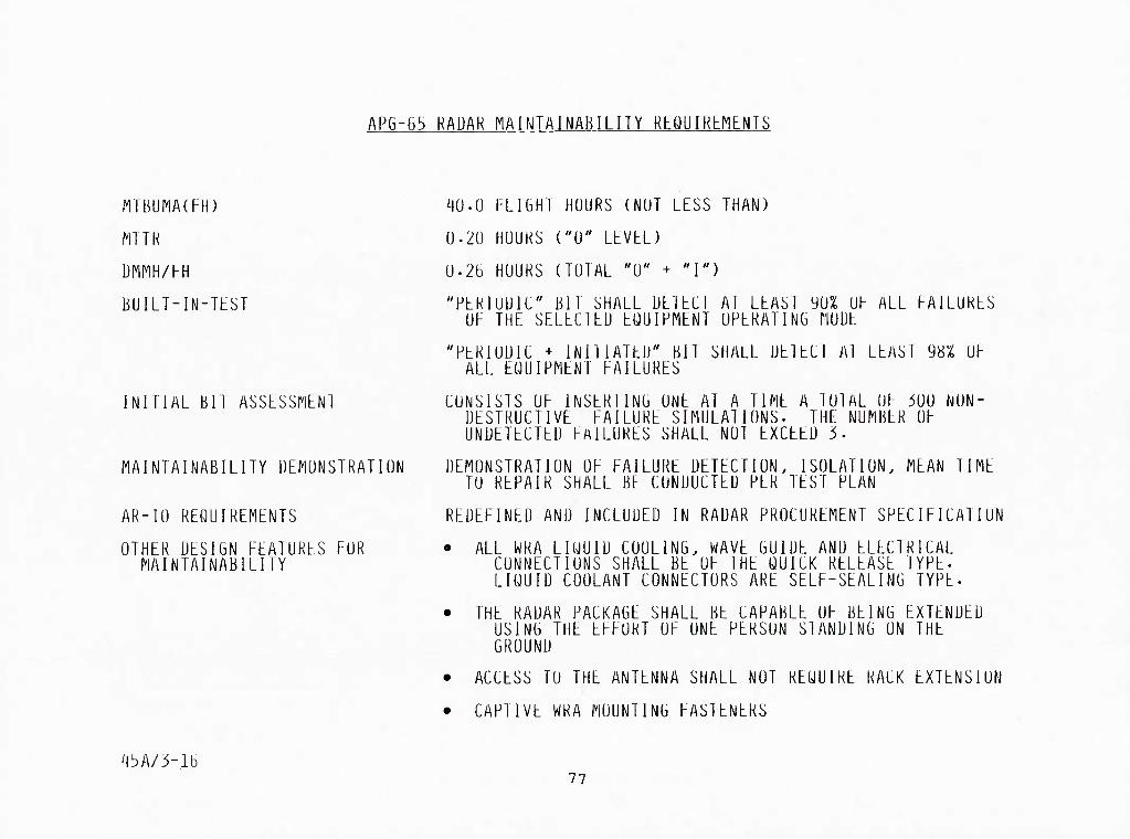
MTBUMA(FH)
MTTH
DMMH/FH
BUILT-IN-ltST
APG-65 KADAK NAINTAINABILITY RbQUIKbMENTS
40.0 FLIGHT HOURS (NOT LESS THAN)
0-20 HOUKS ("0" LLVLL)
0-26 HOUKS (TOTAL "0" + "I")
"PLKIOUIC" Bll SHALL ULILCl Al LLAST yU% OF ALL FAILURES OF THE SELECIEU EQUIPMENT OPERATING flOUE
INITIAL BIT ASSESSnENl
MAINTAINABILITY DEMONSTRATION
AR-10 REQUIREMENTS
OTHER DESIGN FEATURES FOR MAINTAINABILITY
"PERIODIC + INIIIATEU" BIT SHALL UEIECI Al LEAS ALL EQUIPMENT FAILURES
98% OF
CONSISTS OF INSERTING ONE AT A TIME A 101AL OF iOU NON- DESTRUCTIVE FAILURE SIMULATIONS. THE NUMBER OF UNDETECTED FAILURES SHALL NOT EXCEED 3.
DEMONSTRATION OF FAILURE DETECTION. ISOLATION. MEAN TIME TO REPAIR SHALL BE CONDUCTED PER TEST PLAN
REDEFINED AND INCLUDED IN RADAR PROCUREMENT SPECIFICATION
• ALL WRA LIQUID COOLING. WAVE GUIDE AND ELECTRICAL CONNECTIONS SHALL BE OF THE QUICK RELEASE TYPE. LIQUID COOLANT CONNECTORS ARE SELF-SEALING TYPE.
• THE RADAR PACKAGE SHALL BE CAPABLE OF BEING EXTENDED USING THE EFFORT OF ONE PERSON STANDING ON THE GROUND
• ACCESS TO THE ANTENNA SHALL NOT REQUIRE RACK EXTENSION
• CAPTIVE WRA MOUNTING FASTENERS
4bA/3-lb 77

BUILT-IN-TEST REQUIREMENTS
The basic NAVAIR AR-10 requirements were redefined and incorporated into the radar
procurement specification to assure that MCAIR would, as a minimum, meet or exceed the
MCAIR built-in-test requirements to the Navy, As a direct fallout of incorporating a
comprehensive BIT program employing digital circuits, SRA isolation can be accomplished
by inspecting the fail flags stored within the processor memory.
45B/7-26
7$

APG-fiS KAHAR HIITI.T-IN-TKST REmi I RF^IF.MTS
• IMITIATFP RIT
'^^''- FAULT DFTFCTIOM
'^^n FAULT lSnL'\TinM (TO WRA)
• PFRinnir BIT
'in"' FAULT nFTFCTIOM
nn'7, FAULT ISdl^ATKlM (Tfl WRA)
• FALSF ALARM RATE <1'^^
'lSA/3-17 79

BIT TEST PLAN
The number of trials for the maintainability/BIT demonstration is determined by the
system MTBF at a 95% confidence level. The faults are randomly selected and proportionally
distributed to each WRA based on the WRA failure rates. A minimum of 95 faults with zero
(0) test failures (all faults detected and isolated) is considered passed. If a test
failure occurred, an additional 30 faults with zero test failures are required in order to
pass. If, at the completion of this demonstration, 338 tests, a point within the accept
region is not obtained, fixed/retest of the test failures is required.
45B/7-35 80

13 T
94
/lOO 150 200 1 BIT FAILURE DETECTION AND ISOLATION
TEST PLAN
250 300 350 400 TRIALS
81

Kmphasis was placed on designing and testing to the "real-world" environments.
Operational Mission Environment (OMK) was used to define the F/A-18 operating conditions
and took precedence over less severe env i rc^nmenta L specifications. This real-world
environment was first applied as design constraints and then used to set the test limits,
83 45B/8-21

The implementation of a realistic Operational Mission Environment (OME) as a basis for
design and test requirements is a key Hornet program initiative which contributes to improved
equipment reliability. Traditional design and test requirements have, in many instances,
been inadequate in representing field operating stresses. As a result, the real-world
operating environment contributes to failure modes that were not considered during design,
nor discovered and corrected during demonstration tests. To solve this problem, realistic
training and combat mission profiles were selected as the basis for a detailed operating
environment of the airplane. As the first step in the OME process, twelve training missions
(based on training syllabus requirements, squadron surveys, and pilot experience) and six
critical combat missions (based on the Hornet Operational Requirement) were defined. A
frequency of occurrence for each mission was then established for Navy Fighter, Navy Light
Attack, and Marine Fighter/Attack squadrons, as well as ship/shore and combat/training
sortie ratios. Allowances were included for combat maneuvers, occasional transient excur-
sions beyond the design flight envelope, ground operation, and handling and storage condi-
tions. The resulting OME definition formed the basis for establishing expected flight
load, vibration, temperature, altitude, humidity, acoustic, salt, and dust conditions.
Critical design points from the OME became "design-to" requirements for all Hornet equipment.
Thus, design and test conditions tailored to the expected environment were derived and im-
posed in the procurement specifications. OME conditions were used in the radar reliability
development test. Accelerated testing approaches were developed to "time-compress" the
design life testing to achieve test span reductions and cost economics.
45B/8-4
84

F-18 MISSION PROFILES (MP) IN DESIGN AND TEST (D&T)
OPERATIONAL REQUIREMENT
VF TRAINING
VA TRAINING
F^^ VMFA
TRAINING VF CRITICAL
COMBAT VA CRITICAL
COMBAT VMFA CRITI-
CAL COMBAT NAVY
TRAINING MP COMPOSITE
COMBAT CRITICAL MP COMPOSITE
GROUND OPERATIONS, ENVELOPE CORNERS, MAINTENANCE, GROUND HANDLING, AND
STORAGE ENVIRONMENTS
DEVELOPED SUBSYSTEM AND COMPONENT CRITICAL PARAMETERS
S NAVAIR APPROVAL
85
MCAIR
aP7«-iis«-st

F-18 DESIGN MISSION MIX
TYPE SQUADRON/MISSION VF VA VMFA
%0F PROCURED FORCE 25 43 32
TRAINING MISSION DISTRIBUTION (SURVEYS AND TRAINING REQ'MTS) 88%
7.5 5.0 STRIKE ESCORT BARRIER CAP 10.8 — . 10.0 FIGHTER CAP G.5 — 6.0 DECK LAUNCHED INTERCEPT (DU) 1.0 — 1.0 AIR COMBAT TRAINING/ACM 20.9 12.0 20.0 AIR INTERCEPT TRAINING 20.0 5.0 — INTERDICTION/CLOSE AIR SUPPORT 12.0 27.0 30.0 LOW LEVEL NAVIGATION/STRIKE - 15.0 17.0
CARRIER QUALIFICATION 3.0 3.0 2.0 FIELD CARRIER LANDING PRACTICE 9.0 9.0 9.0 FERRY/FAM/INSTRUMENTS 9.3 24.0 — SURFACE SUBSURFACE SEARCH — 5.0 —
TOTAL 100% 100% 100%
COMBAT CRITICAL MISSIONS [12%J DISTRIBUTIOI
75.0
1 FOR CONSERVATIVE DESIGN
STRIKE ESCORT 40.0
DLI AGAINST BOMBERS (SAME PROFILE AS T4) 25.0 - 25.0
SUPERSONIC MEDIUM ALTITUDE ATTACK - 5.0 5.0 SUPERSONIC HIGH ALTITUDE ATTACK - 15.0 - HIGH SUBSONIC LOW ALTITUDE ATTACK - 10.0 10.0
SUBSONIC MEDIUM ALTITUDE ATTACK — 70.0 20.0
QP77-0021-«
87

F-18 OPERATING HOUR SUMMARY
SINGLE MISSION
F-18 SERVICE
LIFE
FLIGHT HOURS 1.877 6000.0
ADDITIONAL ENGINE OPERATING HOURS 0.563 1800.0
• MISSION RELATED (TAXI, TAKEOFF, ETC) (0.522) (1667.2)
• OTHER (MAINTENANCE,TRIM, ETC) (0.041) (132.8)
OPERATING HOURS FOR MAINTENANCE 0.630 2013.9
• APU OPERATING (0.530) (1694.2) • EXTERNAL POWER
TOTAL
(0.100) (319.7)
3.070 9813.9 GP76-1150-53
88

SU:V^5V!AP.Y
MDC A3376 AND ADD 1
MDC A4241
MDC A4240
MDC A4252
TO SUPPLIERS FOR DESIGN
AND TEST
MDCA4212 INTEGRATED TEST PLAN
MDC A4238 SUMMARY REPORT
5> MDC A4239 MISSION AND OPERATIONAL ENVIRONMENT
TO NAVAIR FOR
APPROVAL 89

RELIABILITY KAILURbl DEFINITION
Reliability failure definitions were established for the various test/measurement
aspects ot the F-18 program. Reliability demonstration testing basically used the ground
rules of MIL-STD-781 and AR-34. Field teams were deployed both during full-scale development
(FSD) and deployment. Ground rules during FSU included provisions for making a failure non-
relevant if a fix had been identified prior to the field occurrence. (This approach was a
compromise between counting all failure occurrences until the fix was implemented and not
counting repeats of known problems.) This method projected the reliability that could be
expected on the production aircraft.
90 45B/8-5

KELlAblLIlY FAlLUKb UbUNlTIUN
• KtLIABILITY DtMONSTRATION
- MIL-STU-781B "KtLIABILHY lESTS: EXPUNbNTlAL DISTKIBUTIUN"
- AR-34 "GENF.RAL REQUIREMENTS FUR FAILURE CLASSIFICATION FOR
KELIABILIIY TESTING"
• RELIABILIIY MEASUREMENl DURING FLIGHT TESl" AND OPERATION
- MCAIK/NAVAIR MEMORANDUMS OF AGREEMENT
FSD - NON-RELEVANT IF FIX PREVIOUSLY IDENTIFIED
PRODUCTION - ALL RELEVANI
45A/9-3 91

R&M AWARD FEE STRUCTURE
An incentive award fee was issued as part of the basic contract to provide MCAIR an
opportunity to gain awards based on demonstrated aircraft performance in the areas of R and
M. These award fees were then structured to allow major suppliers to participate in the
R&M incentive.
The reliability features of the radar to be demonstrated were MTBF and MFHBF. The
maintainability features were MMH/FH (0-Level Unscheduled), DMMH/FH (O&I Total) and MFHBMA
(O-Level). These requirements were selected to be demonstrated during the production
reliability test, the 1200 FH, 2500 FH, and 9000 FH periods. The incentive award fee was
structured to provj.de 60% of the total award pool to reliability and 40% maintainability.
45B/8-23
93

APG-65 RADAR RELIABILITY INCENTIVE AWARDS
The table shows the radar reliability incentive earned to date. The 1200 flight hour
evaluation was based on cumulative data beginning at first flight and allowed almost no
credit for corrective actions. The 2500 flight hour milestone was fulfilled by the 50-
flight, aircraft reliability demonstration. The production reliability demonstration was
the MIL-STD-781B test conducted at Hughes.
45B/7-29 '
94
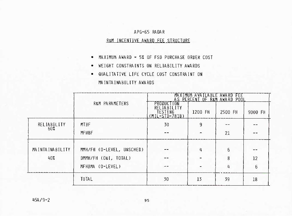
APG-65 RADAR
R&M INCENTIVE AWARD FEE STRUCTURE
• MAXIMUM AWARD = 5% OF FSD PURCHASE ORDER COST
• WEIGHT CONSTRAINTS ON RELIABILITY AWARDS
• QUALITATIVE LIFE CYCLE COST CONSTRAINT ON
MAINTAINABILITY AWARDS
R&M PARAMETERS
MAXIM AS PE
m AVAILABLE AWARD FEE RCENT OF R&M AWARD POO L
PRODUCTION RELIABILITY TESTING
(MIL-STD-781B) 1200 FH 2500 FH 9000 FH
RELIABILITY MTBF
MFHBF
30 9
21
—
MAINTAINABILITY MMH/FH (0-LEVEL. UNSCHED)
DMMH/FH (O&L TOTAL)
MFHBMA (O-LEVEL)
— 4 6
8
4
12
6
TOTAL 30 13 39 18
45A/9-2 95

APG-65 RADAR RELIABILITY INCENTIVE AWARDS
The table shows the radar reliability incentive earned to date. The 1200 flight hour
evaluation was based on cumulative data beginning at first flight and allowed almost no
credit for corrective actions. The 2500 flight hour milestone was fulfilled by the 50
flight, aircraft reliability demonstration. The production reliability demonstration was
the MIL-STD-781B test conducted at Hughes.
45B/7-2y 96

APG-65 RADAR RELIABILITY INCENTIVE AWARDS
MTBF MFHRF
% AWARD THRESHOLD 100% ACTUAL THRESHOLD 100% ACTUAL RECEIVED
1200 FLIGHT HOURS 58 96 37 - -- -- 0
2500 FLIGHT HOURS -- -- -- 53 88 100 100
PRODUCTION R DEMO 85 106 >106 — — — TBD
i|5A/3-18 97

9000 HOUR MAINTAINABILITY INCENTIVE AWARD
The 9000 flight hour maintainability evaluation was conducted by VFA-125, the first
fleet readiness squadron (FRS), at NAS-LeMoore, California. The maintenance was performed
by fleet personnel and observed by MCAIR and Naval Air Test Center monitors. The maintenance
was documented by squadron maintenance personnel on Navy VIUs/MAFs (OFNAV 4790/60). The
data from four production aircraft was used.
During this time Vt'A-125 made three deployments, two to MCAS-Yuma, AZ, and one to
NAS-Fallon, NE. A total of 924 flight hours were accumulated on these four aircraft.
45B/7-1 98

APG-6b KAUAK
9UU0 HR MAINTAINABILITY INCENTIVE AWAKU
MMH/FH (UKGANIZATIUNAL/INTERMEUIATE-LEVEL) EUR 9.UUU FLIGHT HUUkS
REQUIRED - .280 MMH/FH
DEMONSTRATED - -227 MMH/EH
I IMPROVEMENT - 19%
AWARD - MAXIMUM (12% OF TOTAL R&M AWARD POOL)
MFHBMA (ORGANIZATIONAL-LEVEL) FOR 9,000 FLIGHT HOURS
REUUIRED - 36-7 MEAN FLIGHT HOURS BETWEEN MAINTENANCE ACTION
DEMONSTRATED - 42-0 MEAN FLIGHT HOURS BETWEEN MAINTENANCE ACTION
I IMPROVEMENT - 16% -
AWARD (19% OF MAINTAINABILIIY AWARD, 88% OF LOGISTICS BIAS AWARD)
TOTAL 9.000 FLIGHT HOURS MAINTAINABILITY INCENTIVE
AWARD - 80.3% OF AWARD AVAILABLE
45/9-1
99

SOURCE SELECTION
The importance of R&M was clearly established with potential suppliers during numerous
briefings, specific proposal preparation instruction, and firm, demanding specification
requirements. This importance was reinforced by requiring specific data in each proposal.
The data included analysis of and justification for any exceptions to reliability guidelines
and derating criteria. Examples of analysis techniques including FMEAs and predictions
were also required. It was made clear that R&M was a total program concept and that R&M
evaluation would be conducted in all key areas of the proposal including design, manufacturing,
management, and contracts. Numerous special trade studies of alternative configurations
required the input of the potential suppliers. These activities supported the emphasis on
R&M during negotiation.
45B/7-19
100

i|5A/15-16
SOURCE SELbCTIUN
1) CLEARLY ESTABLISH IMPORTANCE OF R&M
A) BRIEFINGS B) REQUEST FOR PROPOSAL INSTRUCTIONS C) HARD SPECIFICATION REQUIREMENTS
2) REINFORCE IMPORTANCE WITH SPECIFIC DATA REUUIREU IN PROPOSALS OVER AND ABOVE
A) CLEAR SUMMARY OF EXCEPTIONS ANTICIPATED TO
- RELIABILITY GUIDELINES - DERATING CRITERIA - ANALYSIS TECHNIQUES - TRADE STUDIES
3) R&M EVALUATION CONDUCTED IN ALL KEY PROPOSAL AREAS
- DESIGN - MANUFACTURING/PRODUCIION PLANS - MANAGEMENT - CONTRACT UAL
NOT JUST THE R&M PROPOSAL VOLUMES
i^) BUYER PERFORMANCE DURING NEGOTIATIONS SUPPORTS R&M EMPHASIS
- REACTION TO SPECIFIC R&M EXCEPTIONS/DEVIATIONS BALANCE IN RELATION TO OTHER FACTORS
- REACTION TO CONFIGURATION AND TRADE STUDY SELECTIONS - IMPLEMENTATION OF KEY R&M PROPOSED INITIATIVES AS
CONTRACTUAL REQUIREMENTS
• SPECIAL TESTS .
101

MANACKMPNT

45/3-19
MANAbLMLNT
- MANAGEMbNl LhPHASlS
MANAGtMbNI CUNIKUL
103

MANAGEMENT EMPHASIS
^11 program participants at all levels must be made aware of the importance of R&M.
This especially includes the designers both at.MCAIR and the suppliers. With many informal
R&M trade-offs taking place daily on the drawing boards, the individual designers have to
be aware of the importance of R&M.
45B/8-24
104

MANAGhMliNT EMPHASIS
• NAVY BRIEFINGS ON R&M NEW LOOK
- fICAIR MANAGEMENT AND SUBSYSTEMS MANAGERS
- POTENTIAL SUPPLIERS
• MCAIK/NAVY
- POTENTIAL SUPPLIERS
- VISITS TO KEY SUPPLIERS PLANTS - BRIEEINGS TO
MANAGEMENT AND RESPONSIBLE DESIGN ENGINEERS
RESULTS: ESIABLISHEU MANAGEMENT EMPHASIS
ESTABLISHED DESIGNER LEVEL EMPHASIS
^Sl\/lb-l5 105

NAVY PROGRAM REVIEWS
Navy program monitoring and sustained emphasis on R&M was evident by the number of
meetings shown in the figure. Special emphasis and attention was provided by the Assistant
Deputy Chief of Naval Material for RM&O. These meetings not only communicated the Navy's
interest in R&M but brought senior contractor management into the meetings.
In the early reviews, the Navy reguired that R&M be addressed in the reviews by the
contractor subsystem manager. This reinforced the idea that R&M was part of the respon-
sibility of the subsystem managers and designers.
45B/8-6
106

i|5A/15-13
NAVY PKOGKAM KbVIbWS Al MCAIK FUR K&M
NOV 5-6. 1975 R&M DESIGN HEVItW KADM HUXGKUVtK. AUM StYMUUR. W. WILLOUGHBY
JAN 19-22. 1976 R&M DESIGN REVIEW
EEB 3-i|. 1976 R&FI REVIEW
MAR 3. 1976 BIDDER INFORMATION CONFERENCE RADM FOXGROVER. W- WILEOUGHBY
APR 1, 1976 R SPECIALTY DESIGN REVIEW
MAY 1976 INITIAL DESIGN REVIEW
AUG/SEP 1976 R SPECIALTY DESIGN REVIEW
DEC 6. 1976 RJiM DESIGN REVIEW KADM JESSON. CAPl LENOX. W- WILLOUGHBY
SEP 1977 . DETAIL DESIGN REVIEW
JAN/FEB/MAK 1977 R SPECIALIY DESIGN REVIEW
MAR 1. 1977 R&M PROGRAM REVIEW
APR 19-22. 1977 CRITICAL DESIGN REVIEW CAPT CARRUTH
MAR 13. 1978 R PROGRAM REVIEW
JUL 24. 1978 R PROGRAM REVIEW
107

(Continued)
During the present program phase emphasis has been concentrated on Navy operational
reviews, but Reliability coordination and Technical coordination between NAVAIR, MCAIR and
Hughes hais continued.
108 45B/8-25

^5A/15-14
NAVY PKUGKAM REVIEWS AT MCAIR FUK R&h (CONTINUED)
DEC 12-13. 1978 R&M PROGRAM REVIEW
AUG 16. 1979 R&M PROGRAM REVIEW
SEP 24. 1979 . R&M REVIEW - CAPT LENOX
JAN 27. 1980 PREPROUUCTION RELIABILITY DESIGN REVIEW - W. WILLOUGHBY. RADM JESSON. CAPT LENOX. CONUUCIEU Al WASHINGTON. UC
FEBRUARY 1980 TO PRESENT
• TECHNICAL COORDINATION MEETINGS AT MCAIR/HUGHES - BIMONTHLY
• NAVY OPERATIONAL AND MAINTENANCE REVIEW - UUARTERLY SINCE JANUARY 1982
• NAVY/MCAIR R&M REVIEWS - SEMIANNUAL
109

OME AND YOUR APPROACH TO DESIGN AND TEST
• THE OME SPECS AND DOCUMENTS ARE THE MCAIR/USN BEST ESTIMATE OF WHAT YOUR EQUIPMENT WILL SEE IN SERVICE
• THE FLIGHT DEMONSTRATION PROGRAM WILL SIMULATE OPERATIONAL USAGE
• WE WILL ALL BE JUDGED IN THE FLIGHT DEMO PROGRAM
• THE SUCCESS OF OUR PROGRAM DEPENDS ON OUR PERFORMANCE DURING THE FLIGHT DEMONSTRATION
TAKE IT SERIOUSLY DON'T DESIGN TO PASS SOME LAB TESTS OUR F-18 WONT FLY IN A LAB

MANAGEMENT CONTROLS
Collocation of R&M engineers with design engineers at MCAIR provided for effec-
tive coordination and communication throughout the program.
45B/8-6A
112

i^5/3-20
hANAGLMENT CONTROLS
• REQUIREMENTS/RESPONSIBILITY FLOW TO DESIGNER LEVEL
- AWARE OE ALL REQUIREMENTS
- EQUAL RESPONSIBILITY EOR PEREORNANCE/RELIABILITY/MAINTAINABILITY/
COST (QUAD CHARTS) REPORTING AT ALL REVIEWS
• SCHEDULES AND MILESTONE CONTROL
• COLLOCATION OE R&M ENGINEERS WITH DESIGN ENGINEERING AT MCAIR
113

RADAR SE"
% DRAWI^•GS RfLEASEO
(BY WEIGHT)
90 -
80 -
ra- t
60 -
50-^ PHUC SPEC
iBr.
40-
30-
20-
10-
n
WBS 1340.01 SUBSYSTEM MANAGER: L.A. LEMKE
WEIGHT EMPTY
TABCET: 425 LB CURRENT: 425 LB OVEd/UNDER: 0 a
s OVI"
IICMI V
iiiJl
I I I I M , i I I
I ' I M i M i I (Fl mCLUOlO .!ii
!,il I
Ml
I i I -4- -l-M llill
PT'I ill'''! Ll|,Li,ljJ,
iliJJJH I I I
'■■'H
' ' Hi
AVG UNIT PRODUCTION COST - 219 AIRCRAFT THEN YEAR DOLLARS IN THOUSANDS
ALLOCATION: HEALLOCATION:
I
CURRENT: 0VER/UN0ER:-J1Z0
h-
iil
iiilLllJ
MEAN TIME BETWEEN FAILUnES (MTBF)
ALLOCATION: 106 HR GFE EXCLIJtJfO 0 REALLOL'MVIOK: 106 Hfl CURRENT: 106 HR CVfti/UNCER: 0
simDin
ID
It
10
WlicmilTU
C(( ONIY
5
ID
15
in
-LLU_1.
illMi I ' i ' 1 M ! iiUi i.lJ
I U-l I ! I M i I
1-Li
i-i
ill,; 1.1 i!
4 lu. J-lJ
);i|.:-M-i.H-i-i ' ' ' ' I'll
I ! ,,...
LLuJiLiJjl.i.iUi-iJiii.i!:.i:Iiiiu Ji),*liO*in/ f MAM jli.A SO:N D.J P v*M , ; k l 0 - o
-I-1-
il.i.iliU- i I ' I ' I I I I
I I
* on* 4
J
OIC 41 OIJfCII»t w' CM oxir
7
% UNOIK
ILlil.li
i' I' 11
MM
"TT ' ' I ! ; M T i 1 : lllll IM : IIM' 'I
• ' tHjH[-::r|r'-t-rrr
MHO «■
1-1 I I-; I i M ; , i M I I I ! ill
^-^ ^ftt- 14- - -
14 -im ̂-'-!
|;flrfr|-llH-iT Mir.-.l I I I M|*^M,J,J * i U .1 UU/ MAM i|i^* IjOjl 0
n<t;' ' I "" iv; '
i ' I I ' ! M M M h t
mill ' I i
lllUii ._.^ __ _i I M 1
t * MA,Ml i'J A ( 0 4 If
UNSCHEDULED MAINTENANCE MANHOURS PER FLIGHT HOUR (MMH/FH)
A:.LOCATION: 1.13 HR RtALLOCATION: l.ll HR CURRENT: 174 HR OVER/UNDER: ♦0.14 Hfl
r;; M ; ; 1 M M M M M ' I ; 1 ;! OCIOK* I9't
15 I-
% OVtD ; ■ , j ID M I , M . M I I M-LI-f-^-i-i-Uj-l
I J ! . 11 I M h I h I
;u4uail..-(ilL.LLU.iL ■i.iii.MLm;i[gi.Uiii-ii
I
I M • t ! M ! I
i-uiii-L:- M I I ' M ! I oisicxin 10- . i M ' 1 I ' M M M M 1 M
•loiiiKiMiiii ^-^*-l—Ln-'-i-^-i I |l I jl I I I M I I I 1 1 : M
% UIOER
10 I
15
n
! i : 1 ; i I i ' , ' ' i ' I I ' I jl I i ■ ! ■ ■ ■ ' Ml,-! Lj-f -I MM I Ifl (.|l;.i_,_,
!|.i:iM,i|i;.UJi-lL|L!i.i. ■ '' i: I ; i i i ' M J ' I I
}|.U.|h!(lli.lil(:. M ! M 1 I I I
Uii-liulLUilLLLl! ''SJ6 I ' ' ' \vj' ' ' " 1 ':•*■{ ^ - ■ - \
G^rr-^'eM 111
114

WRA: RADAR SIGNAL PROCESSOR REA: E. B. CLAPP
WEIGHT (POUNDS)
•.lOWTIW: 52.6 CWW1P: ^^' ^ («' 50 jTjir" «• » 404
+1.5
AVG UNIT PRODUCTION COST - 114 S/S (REAL TIME MFG. COST $K)
<XHnm: IWTVUMC* +86.0
MEAN TIME BETWEEN FAILURES (MTBF)
^^p^"'"* ,300 a^„ 440 t^./tmn^i +140 SrSTfx -^^^ «0. US, gp
60
X OVER 40
20
DESIGN- TO RQMT
20
% UNDER 40
60
u=i
=i J4
UNSCHEDULED MAINTENANCE MANHOURS PER FLIGHT HOUR (MMH/FH)
»u(x:«Tiwj_ .0510* cvwtin: 60
40
% OVER 20 DESIGN- TO RQMT
20
40
60
80
100
% UNDER
"^ RrALL'0OTTn3~g/77~ ** REALLOCATED 10/77
.0297
»|jH|i.ij|iiW7 I9r9 I Itn
prtyyiiec^ - .02
._
U
-u
IHE
115 + PRODUCTION UNIT NO. 5 ACTUAL

FORMALIZED REQUIREMENTS TO IMPROVE CONTROL
1976 J A S 0 N D
1977 JFMAMJJASOND J F M
1978 A M J J A S 0 N D
REL DESIGN REQUIREMENTS A
REL & QUAL PROGRAM PLAN A
CRITICAL ITEMS PLAN A
INTEGRATED CORRECTIVE ACTION PROGRAM
A
FAILURE REVIEW BOARD A A
QUALITY REVIEW BOARD A
FAILURE DATA MANAGEMENT
FSD FAILURE REPORTING A
MFG DATA ACQUISITION ■ A
DATA COMPILATION A
DATA ANALYSIS A
ASSEMBLY SCREENS A
COMPONENT QUALITY REQUIREMENTS
A
MFG TROUBLESHOOTING A
45/15-14
117

CRITICAL ITEM RELIABILITY CONTROLS
The purchase order included specific requirements for a variety of measures directed
at R&M assurance. Hughes established formal internal requirements documents containing
detailed procedures for implementing these purchase order provisions. The following chart
indicates that these requirements were selectively passed on to suppliers of key ele-
ments/devices within the radar.
118 45A/17-1
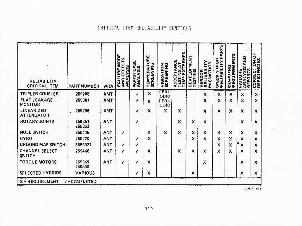
CRITICAL ITEM RELIABILITY CONTROLS
RELIABILITY CRITICAL ITEM
TRIPLER COUPLER FLAT LEAKAGE MONITOR LINEARIZED ATTENUATOR
ROTARY JOINTS
NULL SWITCH GYRO GROUND MAP SWITCH CHANNEL SELECT SWITCH
TORQUE MOTORS
SELECTED HYBRIDS
PART NUMBER
269205 260361
259296
259351 269352
259445
259270
3556927
259446
259349 259350
VARIOUS
WRA
XMT XMT
XMT
ANT
ANT ANT ANT ANT
ANT
Ui
It <4
• •
UJ
h OS
CD BC
X
X
X
X X
X
X
X
PERI- ODIC PERI- ODIC
X
LU
z<SE
U UJUJ
X
X
z UJ
§§ UJ UJ
X X
ii ogy
UJ UJ ce >QC£
X X
X X
X X
X X X X
12
P OK
X X
X X X X
o z <
LU — W)
S ^ o. <ZuJ
X X
X
X
X X X X
X
X
u.
Z UI 25 HZ Uuj UJ —
ecu.
X X
X
X
X X X X
X
X
X'REQUIREMENT /-COMPLETED
JULY 1977
119

HKsrc.N

DESIGN
DESIGN OVERVIEW
• DESIGN TRADE STUDIES
• PKEDICllUNS AND ANALYSES
• DESIGN GUIDELINES
PARTS AND DERATING
BUILl-IN-TEST
4b/8-7 121

TECHNOLOGY UTILIZATION THAT IMPROVED RELIABILITY
■The keys to the achievement of the reliability specified for the APG-65 radar are the same keys which permit the achievement of the dual-mission, multimode performance capabil-
ities: The capability to perform high speed, wide dynamic range analog-to-digital conversion
of the radar return coupled with the availability of low cost, low power, high density, high
speed digital devices enables the fully programmable processing of air/air and air/ground
radar returns in addition to the previously implemented digital processing of target data and
radar control functions. In effect, software complexity has been substituted for many dis-
crete analog processing circuits. The other items listed represent additional examples of
reliability enhancement resulting from technology advances.
45A/17-2
122

APb-b5 RAUAR DESIGN - ThCHNULOGY KLYS TU KbLIAblLITY
• HIGH SPEtU. 12 BIT DIGITAL-ANALOG CUNVERSIUN
- PLUS HIGH SPLLD DIGIIAL PRUCLSSING
- CONVERTS ANALOG HARDWARE TO SOFTWARE
LOW NOISE PET REPLACES PARAMETRIC AFiPLlPIER
PERMANENT MAGNET GRIDDED TRAVELLING WAVE TUBE
GUNN DIODE LOCAL OSCILLATOR
PDI VS. SEPARATE CW MISSILE ILLUMINATOR
4 MBIT DISC BULK MEMORY
ELECTRIC DRIVE ANTENNA
HIGH EEPICIENCY COOLING EOR LOW COMPONENT lEMPERATURES
45A/lb-12 123

DESIGN HIGHLIGHTS FOR IMPROVED R&M
The features noted here are examples of design choices which provide R&M benefits in
addition to cost, weight and performance benefits. Some of these features were directly
specified in terms of R&M requirements, while others were selected as a result of mechan-
ization trade studies.
45A/17-3
124

APG-65 RADAR - DESIGN HIGHLIGHTS FUR IMPROVED Rm
• LOW PARTS COUNT - 13.500 PARTS
• ANTENNA FEATURES:
- ELECTRICAL DRIVE .
- NO TACHOMETERS
- NO BORESIGHT REOUIRED UPON ANTENNA REPLACEMENT
- NO ROLL GIMBAL
- REMOVABLE SERVO PART OF ANTENNA ASSEMBLY
- ALL DIGITAL INTERFACE
- FAN/PENCIL BEAM AND NULL HORN SWITCHES
- ANTENNA ARRAY - VIBRATION ISOLATION
• THERMAL DESIGN - 60°C TYPICAL JUNCTION TEMPERATURE
• GUN DIODE LOCAL OSCILLATOR
• FET RECEIVER LOW NOISE AMPLIFIER
i|5/8-9
125

APb-65 RADAR DESIGN HIGHLIGHTS HUk IMPHUVliD K&M (CONTINUED)
NOSE PACKAGE WRAs ISOLATED FROM GUN GAS
SKA, MOTHERBOARD ORIENTATION - VERTICAL (LIQUID WATER PROTECTION)
HIGH VOLTAGE ARCING PROTECTION (FARADAY SHIELDS)
LOW POWER IC LOGIC USED TO REDUCE JUNCTION lEMPERATURES (SCHOTTKY.
LOW POWER SCHOTTKY. TTL)
MEMORY - SPERRY MAGNETIC DISK. 156K lb BIT WORDS
GRIDDED TWT - PERMANENT MAGNET FOCUS. BEAM SCRAPER
RADAR SIGNAL PROCESSOR - SOFTWARE REPROGRAMMABLE " ■'
THREE ENGINEERING MODEL DEVELOPMENT SETS COMPLETED BEFORE DELIVERY OF
FIRST FSD RADAR SET
ALL WRAs REMOVABLE FROM GROUND LEVEL - NO STANDS REQUIRED
NO ADJUSTMENT REQUIRED ON WRA REPLACEMENT
45/8-10 127

APG-65 DESIGNED-IN RELIABILITY AND MAINTAINABILITY
MCAIR considered the Hornet reliability requirements as being especially challenging
and impleTTiented many actions in the management, design, and test areas to ensure that these
requirements would be achieved. The MCAIR subsystem manager responsibilities in the
reliability area were delineated and reliability engineers were integrated into the design
process. By collocating the reliability specialists with the subsystem managers and
designers, all design details could be reviewed for reliability impact, resulting in maximum
influence on the evolving design. Also, an extensive formal trade study process was used
to evaluate any significant proposed changes to the baseline design. All trade studies
were evaluated for reliability and maintainability impacts, along with the usual performance,
weight and cost impacts. (Over 400 formal trade studies were completed during the design
phase.) Periodic design reviews at suppliers, at MCAIR, and with the Navy, provided final
assurance that reliability was being adequately considered in the design process.
Many of the accepted standard approaches to ensuring high equipment reliability are
utilized on the Hornet program. Examples of these established techniques include reliability
design-to-allocations, periodic assessment of status for each subsystem manager, failure
mode and effects analysis, an approved parts list, selective use of Sneak Circuit Analysis,
and use of a Closed Loop Evaluation and Reporting (CLEAR) system to report and track all
equipment failures.
45B/7-32
128

APG-b5 DbSlGNLD-lN HhLIABlLlTY ANU MAINTAINAHIIITY
• K&M SPECIALISTS INPUTS AT ULSIGN STAGh
- TRADE STUDIES
- REVIEW AND COMMENT SHEETS
- MONIIURING AND REPORTING
- INTERNAL DESIGN REVIEWS
ALLOCATIONS TO DESIGN LEVEL
FIRM DESIGN GUIDELINES
FIRM DERATING CRITERIA SPECIFIED
DESIGN TO MEET F/A-18 OPERATIONAL MISSION ENVIRONMENT
ANALYSIS TOOLS
- FAILURE MODES AND EFFECTS ANALYSIS
- STRESS ANALYSIS , . ;
- SNEAK CIRCUIT ANALYSIS
• STANDARD PARTS PROGRAM
45/8-8 129
F/A-18 RELIABILITY DESIGN GUIDELINES
Extensive reliability design guidelines were established for all F-18 avionics. These
guidelines were required to be reviewed in depth as part of the potential supplier proposal
effort. Any exception required approval by MCAIR and all other elements of the guidelines
became specification requirements when the contract was awarded. Hughes accepted the ob-
jectives of the guidelines with only a few minor exceptions. Later in the program, specific
elements of the guidelines, such as the derating criteria, were made requirements of the
radar procurement specification and the basic document remained a guideline.
45B/7-20
130

F/A-18 RELIABILITY DESIGN GUIDELINES
AVIONIC EQUIPMENT
OBJECTIVE; DESIGN TO HIGH RELIABILITY STANDARDS FROM THE OUTSET
GUIDELINE (93 PAGES) ENCOMPASSES; _
ELECTRONIC PARTS
ELECTRICAL/MECHANICAL PARTS •
ELECTRONIC PACKAGING
MISCELLANEOUS PARTS
PARTS DERATING
DESIGN PRACTICES
TESTING
GUIDELINE IMPLEMENTATION;
• HUGHES ACCEPTED
THE OBJECTIVES OF THE GUIDE-
■ . LINES WITH ONLY A FEW SPECIFIC
MINOR EXCEPTIONS .
45A/8-11
131

TRADE STUDIES
The following two charts provide selected examples of mechanization trade studies
performed during the preliminary design of the APG-65 radar. In general, cost, size,
weight, performance, reliability and maintainability were considerations in each
trade-off. In the great majority of cases, the selected mechanization provided a
reliability advantage (often in addition to advantages in several of the other areas
noted) over the other mechanizations considered.
45A/17-4
132

—l,±i— F-18 TRADE STUDY STATUS
NUMBER OF
TRADE STUDIES
Contract Go-Ahead
Start Complete Cancelled
600
500
400
300
200
100 -
oF7r-ooe2-i
133

HECHANIZATinN TRADE STimiES
WRA
ANTENNA
FUNCTION
filMBAL DRIVE
GIPIRAL
SELECTED MECHANIZATION WRA
DESCRIPTION riTRF
DIRECT ELECTRIC DRIVE
NO ROLL AXIS 1450
ALTERNATE HECHANIZATION WRA
DESCRIPTION MTRF
HYDRAULIC DRIVE
ROLL GIMRAL 556
RECEIVER/ EXCITER
RF PREAMP
PD TWT DRIVE
tLHTTER PROCESSING
FET
GlINN OSCILLATOR
SOFTWARE
PARAMP
fiOO nHLTIPLIER CHAIN
ANALOG HARDWARE
404
TRANSniTTER TWT DRIVE CONTROl AUTO SATHRATION CONSTANT DRIVE 1630
COOLING, DIELECTRIC LIOIIID GAS, SOLID. LIODID 044
RADAR SIGNAI LOGIC MECHANIZATION STTL DHPLEX PROCESSOR
MODIH E COOLING. FLOW THRU, FLAT PARTS PACKAGE PACK
ECL SIMPLEX
355 EDGE COOL. DIP 154
RADAR DATA PROCESSOR
PROGRAM MEMORY MAGNETIC DISC 600 EAROM 517
45C/l-q 135

PULSE DOPPLER VS CW ILLUMINATION
One significant trade study performed during the proposal was the use of radars high
PRF pulse doppler waveform in lieu of a separate continuous wave (CWI) illuminator. This
addition df the CWI would have required 0.6 cu. ft. of space and increased system weight by
34 pounds. The reliability would have been adversely affected with a predicated decrease
in system MTBF by about 6 hours. Since no significant performance advantages were present
with CW illumination, this feature was eliminated.
136 45B/8-26
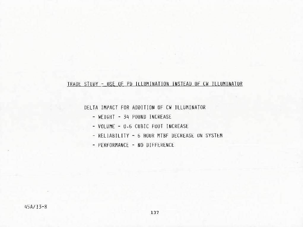
45A/13-8
TRAUb STUUY - USE OF PD ILLUMINATION INSTEAD UF CW ILLUMINATUR
DELTA IMPACT FOR ADDITION OF CW ILLUMINATOR
- WEIGHT - 34 POUND INCREASE
- VOLUME - 0.6 CUBIC FOOT INCREASE
- RELIABILITY - 6 HOUR MTBF DECREASE ON SYSTEM
- PERFORMANCE - NO DIFFERENCE
137

FLATPACK (FP) VERSUS DUAL-INLINE (DIP) IC PACKAGE TRADE STUDY
FLATPACK PROVIDES A 2/1 RELIABILITY ADVANTAGE AND AND 2/1 VOLUME ADVANTAGE OVER DUAL-INLINE IC PACKAGE. BOTH ADVANTAGES STEM FROM THE FLOW-THRU HEAT EXCHANGER MODULE CORE UTILIZED WITH THE FLATPACK PACKAGE. THIS MECHANIZATION REQUIRES SUBSTANTIALLY LESS VOLUME AND PROVIDES MUCH LOWER COMPONENT OPERATING TEMPERATURES THAN ARE OBTAINABLE WITH TfiE EDGE COOLED CARD MECHANIZATION WHICH MUST BE EMPLOYED WITH THE DIP PACKAGE. THE FOLLOWING TABLE SUMMARIZES THE SIX CONFIGURATIONS STUDIED.
DVBION
MA» IMUM NUMBl M OF
IC LOCATIONS ftn MODULE '
SIZE. INCH! s
M W PITCH
COMJiONl NT PACKAGE
TYPt? COOLINO Mt THOO
T
IC MEAN MAXIMUM^
MTiF UNIT
Mouns SVSTCM
NUMIIEO OF MODULES HEOUIRED'
NUMHt nOF MODULE
CONMFCTOn PINS*
TOTAL NUMifn OF
INTEflCONNtCTIONS ncauinio*
UNI r WEIGHT
BOUNDS*
r UNIT
VOLUMI rilT3 >
A ftO B 0 > ft 0 <• 0 36 DIP EDGF 75 «3 156 94 96 t03,l*4 • 3 3 t M ■ 15 »R . ftO« 035 DIP EDGE 76 103 166 94 • 5 160 102 ■>*% • 2 3 1 n C BO 4 ■ ■ 3 S * 0 60 f P FLOW TMHOUGM ■« 76 199 i3i .0 163 B3 VB4 54 1 1 40 O ttS BOiiSO'0 35 DIP EDGE 73 loe I6f 97 49 740 103 »80 76 6 1 64
* 168 5 0 ■• 0 - 060 FP FLOW TMROUfJM 60 76 3?7 136 7« 250 • T,62« 4r 7 0 11 r 11 3S3 50 ■ t 0 ■ 060 FP FLOW TMROUGM 5« 76 366 140 19 304 i3.<14 .., 0 93
NOTES
* EACH LOCATION tS FOP ONE IBPIN IN T t G « A Tt D C I nc U
ON A CONSTANT B3 PERCENT UT IL IZ A 1 ION OF THESE LOCATIONS A CONSTANT flsr K. nEQUinfMENI OF 39^6 L OC A T IONS MODULE COUNT WAS BASED
DIP IS DUAL IN LtNe. FP IS FLATPACK
* '-''-'^''^""^'':'r:.\l\tol'i:^^^ —<^ O' -E„co.«cT,o.s. THUS. „<e ,„,.c,r.. «,u«,uTv ,«ro„
• .T.ND.-,D FOn« .ND ,l.Dt S..P CONNEC.ORS «,T.. O > .NCM SQU.Rf GRID FOR l.T,„ R » „,„( „„.P,r,o OR MULTILAVfRITCMfO CIRCUIT MOTMFRHUARD
ON. SO, OFR X,,., FOR t.„ COMPO.,., ..„ COM..C,On ..„ F.US ... M„n... ,0 MOOUI.E I. r. RCO..F C, IO« .FFO.O TO IMP. FMFNT . «H O.SIC.N
"»'^n\\°\::::i.r:':"r'lV:\'.l\^^^^^^^ -"-' '"'^^-.^,.0 ,- . CROSS S.CT.O. ,„.T I, COMP.,I..F ^I,., ,«, , ,. ,NS,....T,O~ ..V^.OP..
138

ULSIGN KbLAlhU ANALYSbS
BLOCK DIAGRAM AND MATH MUUhL
ALLUCAl lUNS ANIJ PKtUlCTlUN
STKtSS ANALYSIS
LNVIKUNMLNIAL ANALYSIS
FAILUKL MUUbS AND bhhtCIS ANALYSIS
SNLAK CIKCUIT ANALYSIS
PLKIUUIC ULSIGN RLVILWS
^b/8-2:^
139

ANALYSIS KhSULTS
F-I8 HAUAR KELlAblLlTY DESIGN ANALYSES
ANALYSIS APPLICA11UN KtSULTS
FAILUKE MUUES & EEFECTS WRA INPUT/OUTPUT
CRITICAL-VULNERABLE ITEMS
GROUND RAUIATIUN-WEIGHl UN WHEELS LUGIC ADDED
DISC MOTOR START - FIRM- WARE ADDED RECEIVER PRUTECIIUN - ADDITIONAL BIT ADDED
SNEAK CIRCUIT LVPS. TRANSMITTER (NO RF), ANTENNA SERVO
COMPLETE - NO MAJOR PROBLEMS, DRAWING CHECK
WORST CASE CRITICAL DESIGN ITEMS AND FUNCTIONS ECL TEMPERATURE GRADIENTS TIMING CLOCK SKEW NOISE FIGURE
THERMAL & ELECTRICAL STRESS
DERATING COMPLIANCE
COMPONENT SELECTION
MTBF PREDICTION
INITIAL - 42 OVERTEMP CURRENT - 17
INITIAL - 111 OVERSTRESSED CURRENT - /b
45/8-21 140

TABLE 4-2. PROJECTED RELIABILITY
Adjusted for MIL-HDBK-217B 4KMOSRAM "K" Projected Allocated Predicted MTBF Industry Data Factor MTBF MTBF
Antenna
Transmitter
Receiver/Exciter
Radar Data Processor
Radar Signal Processor
Equipment Rack
Waveguide Assemblies
Total
1 , 370
1 128
1 110
832
426
43, 800
55, 600
-4^>
-^
1,210
570
164 195
1.6
1.7
1.4
1.3
1, 3
5.0
2.0
1.42
860
665
790
930
440
8,800
27.800
137
700
700
800
600
300
8,000
10.000
106
141

MTBF PREDICTION PER MIL-HDBK-217B IS 164 HOURS
1500
c 3 O I
m
s
1000
500
[ I PREDICTION
106 HOUR ALLOCATION
1370
i700^
1130 1110
;800^
835
^600 j; 427
77?77y ^300$
24,500
ANTENNA TRANSMITTER RECEIVER/ RADAR RADAR RACK EXCITER DATA
PROCESSOR SIGNAL
PROCESSOR WAVEGUIDES
142

PREDICTED FAILURE RATE BY PART TYPE (ROUND NUMBERS)
■^^ ■~^
y/^ 36 COMPLEX ^^\
/ ITEMS V / (DISC MEM. TORQUE \ / MOTORS \
/^\^ 1200 FPM 400 MOS RAM ICs 1700 FPM \
/ GTWT ^'"^^^ \
500 FPM ^
i^ -__^^
\ 6600 OTHER PARTS / ^^^^~^^~~~~^ _^ \
-
\ (SEMICONDUCTORS. / /
r / \ PASSIVES. ETC) / \ 900 FPM / 1 4700 ICs
1 1200 FPM /
\ / HYBRIDS /
/
F 18 RADAR
%. / bUU l-KN 1^^ TOTAL ~ 6100 FAILURES PER MILLION HOURS (FPM)
JULV 1977
143

THERMAL ANALYSIS AND DESIGN
Following the design process to minimize the parts count, and a selection/screening
process to obtain good quality parts, the single most important factor affecting reliability
is good thermal management. This becomes doubly imjiortant in that military applications
traditionally supply smaller quantities of cooling air and at higher temperatures than
their commercial counterparts. To meet the low component operating temperatures dictated
by reliability requirements, Hughes has developed a unique thermal design concept, applied
first to the F-15 radar and then refined still further on the PVA-18 radar.
This concept consists of a lightweight aluminum heat exchanger sandwiched between two
multilayer printed wiring boards. Cooling air passes directly through the core and is
referred to as a "flow-through" module. This concept provides an extremely short thermal path
to the component, being equal to the thickness of the printed circuit board itself.
Experience has shown that this technique reduces the average temperature of the board
mounted components by 15° to 20°C below that offered by alternate cooling schemes.
A computerized thermal model of the module is developed early in the design phase to
provide rapid evaluation and optimiztion of the component layout for minimum temperatures.
The thermal model is augmented by a library of parts potentially selectable by the
circuit designers and contain thermal impedance information (junction to case).
As the circuit design and product design evolves (i.e., identification and layout of
parts), specialized forms are filled out stipulating the type and location of ICs on the
module surface. This information, along with the previously generated thermal model and
library of parts, permits a computerized thermal analysis to be performed in short order—
before the product design is frozen.
The result is an identification of each component's temperature listed in tabular
form, in addition to displaying a 3-dimensional thermal map. Hot spots are eliminated by
repositioning hot components to cooler areas.
45B/7-39
144

The component layout of a module is reconfigured several times during the design phase
as the result of the rapid thermal analysis capabilities, thus allowing optimization of the
thermal design before the drawings are complete and ready for release.
45B/7-40 145

147

APG-65 RADAR PARTS AND DERATING
The baseline for F-18 parts derating requirements was the NASA guidelines. As part of
pre-award trade studies, standard derating guides were requested from all potential avionic
suppliers. Based upon results received, the NASA guidelines were modified and made more
stringent. The specifics of this derating criteria are shown on the next few charts.
Analysis was conducted in conjunction with reliability stress analysis and prediction and
documented. Any deviation required justification.
An extensive part control program has been in effect throughout the program. Elements
of the program included the MCAIR-established, NAVAIR-approved, Preferred Part List, a
parts control board with membership from all major suppliers (including Hughes), and approved
parts lists for each equipment.
45B/7-21 148

APG-65 RAUAK PAKTS AND DlikATING
45A/8-20
• PARTS DEkATING
- HAKU KLUUIKbMtNTS
- TIGHTtK THAN NASA GUIlJELINtS
• PARTS CUNTKUL PRUGKAM
• PRbFtRRED PARTS LIST
- NAVAIR APPROVED
• PARTS CONTROE BOARD
• EQUIPMENT PARTS El ST
- SUBMIITAES TO MCAIR EROM HUGHES
- HIGH PERCENT HI-REE. STANDARD PARTS
149

COMPONENT DERATING REQUIREMENTS
The component derating requirements were made a part of the radar procurement
specification and were imposed at specific cooling conditions. The aerating requirements
encompassed microcircuits, hybrids, transistors, resistors, diodes, relays, capacitors and
switches.
45B/7-22 150

COMPONENT DERATING REQUIREMENTS
PART TYPES POWER*
DERATING VOLTAGE DERATING
CURRENT DERATING
MAX JUNCTION TEMPERATURE OTHER
MICROCIRCUITS
TTL
CMOS
110°C
90°C
DIGITAL FANOUT 0.80
OTHER 100°C
HYBRIDS 10!3°C
TRANSISTORS-
GENERAL 0-50 0.60 O.bO 100°C
POWER 0.30 0-60 0. bO 105°C
RESISTORS 0.50
DIODES 0.30 O-bO 0-50 100°C
CAPACITORS 0-30
POWER DERATING FACTOR MUST BE APPLIED TO RATED POWER AT TEMPERATURE
TMAX - TOPER p(TopER) = PRATED X
45/8-12 TMAX - TRATED
151

F.18 PARTS DERATING _ — 1
niCMKIKVITS pinncs
!!■ iKUlSl.
!« ^ IBUIBUKJC^,
WflUI .M .» f*-«t/ tMMrat »<ir*aM. .» .11 rnv •mvvt CWrwil bitc>>W .» ■ M *!•
.n .SO
.» Writ Carvwt
•rt ik> «rc HM c/n^ JiMci. Tap*. la-c »• MTC MM Jw«tlM IN*.
lee'c «■ lOOT Hti Jwtt»- T»». nO'C Hta iio-t m> Tu J.i-<t. TM». aKttrivr, m .» .11 Nmr
IIMT. %«rM .it OwlfMt Cwrrant .M
lire Hi* itrc MM J-«U«- T«-». nrc Ml .40 r«.%.r4 Cvrrfat
lire MI *»«tl~ !»•.
wm m mnlK la-v-llll •iirT OMueicinllct: TtTKtar .H
.H .IS tntitmm «»ll*fft .11 P««Mr4 C«rr«<it
Wrc Iki *»tll»i Irm. ••.IM *«.tw liw«t trrict Mil. lire «■ "] «»• "!.••• I«»»t ll" ClMTMl I.*** J.t>* l«^l Offiat C>Kr«*t t«Mr .M .IS fwmr
•t« •701 0»M IM# b(« .W .40 PanrtfO C«m)H
.at Iap«t **lti«t
.to OHIMI Cwrrtnt IH-C Ml wrc nta Jwactlv* !•«».
.M .t« P«Mr ■•fONM* .a .M
.IS >1i>
«•!. C«.r««l M AIlM wki* cM>i> r»tt«« laa^ ma wrc KM J»Kll«i i«».
ItallH t« M awv IhM TMKISTOM
.K««^-ms£« 1, . -t (1 I •'. ' In
.n
'MI "in"
.It NMtr
.M C«rrMt
tare itoi JiMctiM 1mm- MTC «■ ^\^^ Nxr .» .la h-ar
.to C«rr««t ■mtiM ncni> !w .10 ImiUft Tirwf Llrt |}.II«ln t.rr„t)
WC ita 10I*C NM JMMCIIM 1mm. «Mtlt*M .n
blUtlx .M .ta C*rr«M IMMCHM ^«
.40 .10 f«l|»«> Milvr .n fare NH WO-C «■ J«*cU«l 19^. ntMMt .11
ritt« iffMt ■ M
.It fww
.ta CwrMi C*#K<l«r .n
!M .to f«lta«« itrc Nu larc ftoi j^xtt-i 1mm. CAPATtTORS
MljMtlai .to
.It »*«r • ta C«rfW»t
.M .ta fattiw fare Ml JMKJW iwm.
tmt'ltr Titi lliuol HTC *■
tUll Rica
■it ,01
KsisToas .<•
M«niM ricToa' riaitlfl ar Hmr rUtttt .M
irwii 1«IU TaaultM .SI
WITCHES riu laMtatW (Hi) •• rtia (MC. ■«. Ml)
tjnjlitti mnint racm* IblliUlM Crrwll
tMllllM .n P«Mr Ulri.iail (M) l««M|lM .<• CMiiti Wxiaw* (Mil datar .M
.1 >C»»t—1> rtiMffii .IS CapatitM'
1 taruitla AM—t>«-MM lUtl .? (Cf«*Ml
153
INTEGRATED CIRCUITS JUNCTION TEMPERATURE DISTRIBUTION
The following two charts show, for each of several group of components, the
distribution of operating temperatures for that group of components. Overlayed on
that distribution is a curve of failure rate versus operating temperature for a
typical part within that group of components. For example, in the case of TTL
devices, the mean junction temperature is shown to be 7n°C, some 40°C below the 110°C
limit for that class of parts. It is also shown that the failure rate of a typical
device in that group is nearly 50% higher at 110°C than at 70''C.
154

9
INTEGRATED CIRCUITS JUNCTION
TEMPERATURES DISTRIBUTION
ECL AND NMOS ICi (444)i LINEAR ICi (IBS)
45
IT - 100°C EAN - 59°C
10535
>•
< 3 O
100°C' 69°C
20 30 40 &0 60 70 80 00 100110120130140 20 30 40 60 60 70 80 80 100110120130140
SAMPLE IC FAILURE RATES v$ JUNCTION TEMPERATURE
TTL ICJ (4490)
T - 105°C - fl7°C
>•
< 3 a
IT - 110"C MEAN - 70°C
I I I I 20 30 40 60 60 70 80 BO 100110120130140
JUNCTION TEMPERATURE. °C
20 30 40 &0 60 70 SO 00100110120130140
JUNCTION TEMPERATURE, "C JULV 1977
155

*
^
XpFPM QIODES(627)
SEMICONDUCTORS JUNCTION
TEMPERATURES DISTRIBUTION
XpFPM TRANSISTORS (249)
TXV 2N??22A
Jl I — I Mi I — I — I Bl I ■■ I IM I 1^1 — I I I Q ^—JJWX—J.JiiM_L1«-l-Ml»-Li»-l-—J-—^^J»^ I I > 20 30 40 50 60 70 60 90 100 110 120 130 140 20 30 40 60 60 70 80 80 100 110 120 130 140
JUNCTION TEMPERATURE, °C JUNCTION TEMPERATURE, °C
SAMPLE SEMICONDUCTORS FAILURE RATES vj JUNCTION TEMPERATURE
156
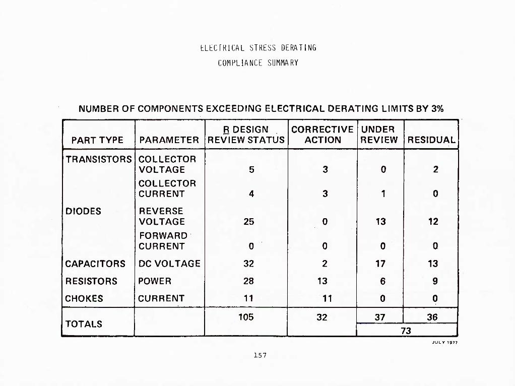
ELECTRICAL STRESS DERATING
COMPLIANCE SUMMARY
NUMBER OF COMPONENTS EXCEEDING ELECTRICAL DERATING LIMITS BY 3% 1
R DESIGN CORRECTIVE UNDER PART TYPE PARAMETER REVIEW STATUS ACTION REVIEW RESIDUAL
TRANSISTORS COLLECTOR VOLTAGE 5 3 0 2
COLLECTOR ■
CURRENT 4 3 1 0
DIODES REVERSE VOLTAGE 25 0 13 12
FORWARD CURRENT 0 0 0 0
CAPACITORS DC VOLTAGE 32 2 17 13
RESISTORS POWER 28 13 6 9
CHOKES CURRENT 11 11 0 0
TOTALS 105 32 37 36
73 JULY 1977
157

DERATING EXCEPTION STATUS
1 March 1977 Data Item - E- 14. 03 Current (May 1979)
Overstresscd Over Temperature Overstressed Over Temperature
Transmitter 38 5 28 0
Receiver/Exciter 7 16 0 3
Antenna 0 2 0 0
Radar Signal Processor 0 0 0 0 "
Radar Data Processor 0 0 0 0
Power Supply Function' 66 19 47 16
SUBTOTAL 111 42 75 19
RADAR TOTAL 153 94
,—^ — ■- 1
1 Power supply parts not included in respective WRA entries above.
15i

DETAILED DERATING EXCEPTIONS
Tranamitttr D«r*lin£ Ewc>plion>
Circuit Symbol Part Number
Ratad V«lu,
D«raltng
AatamMyi HI54Z0 5RA| 3H5400
Capacitor C« p/o «I004I-IB Capacllar C» p/o 9I004I-1B Capacllar c» p/o 9rO04l-0B Capacitor CT p/o 910041-08
Aaaamblri tSIMTS SRAi ISI>400
DC
'DC
400 V 0.4 210V 0.52 400V 0.4 250V O.UI
400V 0.4 250V 0.&2S
400V 0.4 210V 0.52
Olo4a, HV RaclUlar
Dloda, HV RoclKlar
Olada, HV Ractiflar
Dloda. HV Ractiflar
Oloda, HV Racliflar
Dloda, HV Ractiflar
Dloda, HV Ractiflar
Oloda. HV Ractiflar
CR2 925214
CR3 925214
CR4 925214
CR5 925214
CRt 925214.
CR9 925214-
CRIO 925214- IB
CRII 925214- IB
PIV
PIV
PIV
PIV
PIV
PIV
prv PIV
lOKV 0.5 5700V 0.57
lOKV 0.5 5700V 0.57
lOKV 0.5 5700V 0.57
lOKV 0.5 5700V 0.57 lOKV 0.5 5700V 0.57 iOKV 0.5 5700V 0.57 lOKV 0.5 5700V 0.57 IOKV 0. 5 5700V 0.57
3RAi 3515510
Raalator
Raaiator
Rl
R2
RER75F5RilP
RER75r5RllP
Powor
Powar
JOW
30 W
0.5
0.5
17.*W
17.&W
0.59
0.59
Aclual Actual Strcaa Siraia ValtM Ratio CorractlTa Aclloii/Do«Ulloo RatlwuU
Thaaa 400 volt miriar capacltora »ara daralopad for uaa on Iha F-lt pragram. T>ia)r ara hi|h potlad la • 00 volla (twica ralad valual. Lack of room in Iha faradair bo» pravanta uain| a capacitor wllh a hi|har vollaga rating.
Thaaa IOKV high voluga raclinara mmn davalopad for uaa on Iha F-ll program. Full daraling of hlgh- voltaga compenanla would not bo practical in tarma of coil or aiaa. and tha 0,57 alraaa ratio it nol conaidared eacaaaiva for thaaa parla. Tha vendor taala braakdown volUga to ll.KVDC on thaaa parla. Tha IOKV rating la tha point al which laak- aga currant.ia apaclficd.
Rl and R2 mual logathar diaalpata 39.2 walla. Thia powar la dlirldad balwaan Ihaaa two RER75 30-wall chaaala-mounl parla, which ara Iha largaal raatalora availabla on tha F-18 PPL. Thair caaa lamparalura ii hald lo I19"C. Thara la no room in tha modula to add a third raaiator, and tha 0. 59 atreas ratio la not coniiderad cxcaaalvc.
SRAi »i59IO
Capacltar Ct 9I0040-4B
Capacitor 07 9I0040-4B DC
S50V
350V
0.4
0.4
210V
210V
O.t
0.6
AaaamblTi >5I55M »RAi 35I55I0
Tranalalor
Tranalator
04t
Q47
JANTXV2N5303
JANTXV2N5S03
»ov 0.6 54V 0.675
lOV 0.6 54V 0.675
Thci* m«UUt««<l myUr capacltora wara davalop*^ for uaa on the F-18 profram. Thmy ara burnad In at 425 VDC at lOO^C. I^ck of room prav*nla uttn( a capacitor with a hlghar vollag* rating.
JANTX 2N»03S. a 90-volt part (on tha F-li PPL». waa conaidarad for thta application, but rajacted for two rcaaonai
A) 2N503B haa a highar •jc which would raault in a higher JuncMon tamparatura.
B) 2N503() i* not praicntly uaed anywhara In tha F- 18 radar.
Tha alight Iniprovamant In voltaga daraling offarad by tha 2N503H doai not juallfy tta uae to thta application.
159

LfeTAILKD DERATING KXCKPriONS (Continued)
TKANSMIITEK DERATING EXCEPl'IUNS (Continued)
PART CIRCUIT SYMBOL
SRA: 3515390 CAPACITUR CAPACITOR CAPACITOR CAPACI'LXJR
Cl C2 C3 C4
CAPACnxjK C5
DlOUt;, RECTIFIER CR4 DIODE, RECTIFIER CR5 DIODE, RECTIFIER CR9
CAPACITOR CIO
DIODE RECTIFIER CR3
PART NUMBER PARAMETER
ACT'UAL ACTUAL RATED DERATING STRl-JSS STRESS CORRECT'IVE/ACTION VALUE RE(JMT. VALUE RATIO DEVIATION RATIONALE
910034-lB 910034-IB 910U34-iB 910U34-1B
^DC VDC
VDC Vuc
M39022/01-1477 "^UC
JANTXVIN5418 JANTXVIN541B aANTXVIN54lB
PIV PIV PIV
91U040-4B
925436-lB
400V 0.4 270V U.675 These 400-volt PVF2 capacitors 400V 0.4 270V 0.675 were developed for use oti the 4UUV 0.4 270V 0.675 F-18 program. They are hi-potted 400V 0.4 270V 0.675 to twice the rated voltage. Lack
ot rcxsTi in the switching regulator nxxlule prevents using a caijacitor with a higher voltage rating.
600V 0.4 280V 0.47 Itie 0.47 stress ratio tor this polycarbonate capacitor is not considered excessive and does not justify development ot a Larger
type-
400V 400V 400V
0.5 0.5 0.5
270V 270V 270 V
0.675 0.675 0.675 The possibility ot developing a
non-standard part for this appli- cation is teing investigated. The MIL-SPEC calls for a breakdown voltage test to 440 volts.
VDC 350V 0.4 210V 0.6 This 350-volt metallized mylar capacitor was developed for use on the F-18 program. They are burned in at 425VDC at 1U0°C. Lack of room prevents using a capacitor
with a hii_jher voltage rating.
PIV 500V 0.5 270V 0.54 SA7429(925436) is a 500-volt power rectifier, developed specifically for this application. A stress ratio of 0.54 is considered acceptable.
160
55/7-1

DtrrAILKD DKRATING KXCHJFTIONS (Continued)
TRANSMITTER DERATING EXCEPTIONS (Continued)
PART CIRCUIT SYMBOL PART NUMBER
RATED PARAMETER VALUE
ACTUAL ACTUAI. DERATING STRESS STRESS CORRECriVE/ACTION REgMT. VALUE RATIO DEVIATKJN RATIONALE
ASSEMBLY: 3515392 SRA: 3515390
CAPACI'IUR
SRA; 351520 CAPACITOR CAPACITOR CAPACITOR
CAPACITOR
CAPACITOR
CAPACITOR
CAPACITOR
55/7-2
C5 M83421/U1-0168P V[x: 400V 0.4 210 0.52 M83421/01-168B is a 400-volt polycarbonate capacitcir which sees an actual stress of 210 volts. There is no room on the A8A1 printed-circuit board tor a higher-voltaye capacitor. We do not teel that the 0.52 stress ratio is a reliability risk, particularly since there is essentially no AC ripple on the part.
LOW VOLTAGE POVER SUPPLY (R13P) DERATING EXCEPl'IONS
C2 C3 C4
910034-lB 910034-lB 910034-lB
V DC '^DC ''DC
400V 0.4 270V 0.67 400V 0.4 270V 0.67 400V 0.4 270 V 0.67
Prior applications in F-14 i« F-15 do not show a high failure rate. The part is burned in at 500V. A higher rated part would involve a weight and volume penalty.
C7 O>lR06E222JODP VDC 500V 0.4 270V 0.54 Part is only marginally over- stressed and is not considered
excessive.
C9 910035-lB VDC 300V 0.4 160V 0.53 Applied voltage is regulated DC with low ripple.Weight and volume penalty for higher rated part are severe. The overstress is not
considered excessive.
C14
C15
CMR06E222JODP ^DC
CMR06F222JODP VDC
500V
500V
0.5
0.5
320V 0.64
320V 0.64 Parts still provide 180 volts of safety margin.
161

DETAILED DERATING EXCEPTIONS (CONTINUED)
Loo Voltaga Powar SuppIr IRDPI Daralini Eacepi iona IConI'd.l |
Actual Actual Clrcall Rated Do rating Streaa Strrea
P*rt Srn<)>ol Part Numfcar Paramalar Value Reqmt Value R..tio Carrectlva Action/Deviation Rationale
SRAi liUJlO Icon'll
Capacitor CIT MSfOO>/01-2Ml ^DC 20V 0.1 IIV o.ss Overatreaa la not conaldared eaceaalva to Joatify a
Caparilor C2t M)9OOJ/0l-2S4l 20V o.» IIV 0.55 hi|har rated part.
CiH<»*' CIt M)«OI4/O2.|>40 ^DC
lOOV 0.5 64 V 0.64 Volume realrlcllona prevent appllcatloa of a Mfhar rated part.
Ctr»tifw CM .«05>T0-«1B *DC
^DC
tov 0. J JOV 0.4 Overatreaa la not conaldared eaceaalva to juatlfr a
Capaaltor C40 faS>70.9IB JOV O.S SOV 0.6 higher rated part.
Tr«i««tft*r QT f2iSI]-IB ^CC
^CC
4»0V O.i J20V 0.71 Higher rated power Iranalator do not have the
Qi 92sai]-IB 4$0V a.« J20V 0.71 Switching apecd required in the dcflgn.
Tranalator Q* 42Mil.|B ^CC
4S0V e.» 120V 0.71
TranaUtar OIO f2il«l.|B ^CC
4S0V o.t J20V 0.71
DloJa CRI JANTXVIN54lt PIV 400V o.» 270V 0.67 Doaign haa ISO volte or aafety margin. Prior ft-ppli-
D4ada CR» JANTXVINi4ia PIV 400V 0.5 270 V 0.67 cattona on r-14 and F-IS doea not indicate a problem.
mod* CRII f2t4 3b.|B PIV JOOV O.S 270V 0.S4 Part ia only aliRhtly overatreaaed which ia not con- aldared aacaaalva.
Dloda CR2* JANTXVIN54II PIV 400V 0.5 )20V 0.1 The applied voltage la regulated. Higher rated part doea not have the recovery time deaired In the circuit.
DIoda cmi 92SIII.S02B Power jow 0. > I7.9\V O.Ii' Part ia only alighfly overatreaaed. Junction tem- perature ia predicted to be 80^C.
Dioda Cl«)4 42>III-S02B Power sow 0. 9 2 1. 9W O.-H Component junction lemprralura la predicted to be TOOC
LI 986249-IB Current ■ A 0.7 bA 0. T5 Weight and volume penalty prevent uae of higher
lndurlt>r LS 9ab2SS-3D Current I2A 0.7 lOA O.Sl rated pan. (Actual currcnta will be meaaured to verify prrdlclionfl. 1
Inductor l> 9S(>2tS-IB Currant eOA 0.7 SSA 0.»2 ■
Aaitmbly: 35U1J1 SRAi JtlSllO
I7»»C IOO"C I04»C A copper ground plane la being deaigned lo be added Diodr A4CR2t JANTXVINt4ll
Diode A4CII2» JANTXVINS4I( i;5''c IOO"C I04°C tn ciriuit hoard to reduce iunctinn lemperalurea.
Dioda A4CR2i JANTXVIN54U Tj I7S°C IOO°C I0J''C
162

DETAILED DERATI^JG EXCEPTIONS (Continued)
DJW VOLTAGE POWER SUPPLY (RDP) DERATING EXCEPIIONS
PART
ACTUAL ACTUAL CIRCUIT RATED DERATIl^ STRESS STRESS C0RRECTIVF:/ACTI0N
SYMBOL PART NUMBER PARAMETER VALUE RECMT. VALUE RATIO . DEVIATION RATIONALE
ASSEMBLY: 3515231 SRA: 3515210 (con't)
DIODE A4CR29 JANTXVIN541B DIODE, ZENER A4VR2 JANTXVIN3826A 9 175°C 100°C 104°C
175°C 100°C 112°C
ASSEMBLY: 3515240 SRA: 3515240
CAPACITOR C14 M39002/01-01-2529 VQC 20V 0.5 IIV U.55 Cverstress is not considered excessive to justify a higher rated part.
ASSEMBLY: 3515266 SRA: 3515250
RESISTOR A3R8 RNC6H4021FS Etwer 0.125W 0.4 0.06W 0.48 Overstress is not considered excessive to justify a higher rated part.
ASSEMBLY: 3515290 SRA: 3515250
DIODE RECTIEIER A4CR26 DIODE RECTIEIER A4CR27 DIODE RECTIEIER A4CR28 DIODE RECTIFIER A4CR29
JANTXVIN541B JANTXVIN541B JANTXVIN541B JANTXVIN541B
RESISTOR A4RE81 RCR20G151JS CAPACITOR A4C18 M39003/01-2523
Tj Tj
175°C 100°C 175°C 100°C 175°C 100°C 175°C 100°C
106°C 106°C 106°C 106°C
A copper ground plane is being designed to be added to circuit board to reduce junction temper- ature.
0.5 0.32W 0.64 Overstress is not considered 0.5 10.9V 0.54 excessive to justify a higher rated part.
Power 0.5W VDC 20V
SRA: 3515250 CAPACITOR CAPACITOR
CAPACITOR CAPACITOR CAPACITOR
55/7-3
Cl CMR06E222JODP ^DC 500V 0.5 320V 0.64 Parts provide 180 volts of safety C3 01R06F222JODP ^IXl 500V 0.5 320V 0.64 margin. Cost, weight and volume
prevent application of a higher rated part.
C102 C103 C103
910034-lB 910034-lB 910034-18
VDC 400V 0.5 VDC 400V 0.5 VDC 400V 0.5
270V 0.67 Parts are burned in at 500V. Size 270V 0.67 and weight would increase signi- 270V 0.67 ficantly tor a higher rated part.
163

DETAILED DERATING EXCEPIIONS (Continued)
LOW VOLTAGE POWER SUPPLY (RDP) DERATING EXCEPTIONS
PART CIRCUIT SYMBOL PART NUMBER
RATED PARAMETER VALUE
ACTUAL ACTUAL DERATING STRESS STRESS CORRECTIVE/ACTION RECMT. VALUE RATIO DEVIATION RATIONALE
CAPACITOR
TRANSISTOR TRANSISTOR TRANSISTOR
C108 CMR06E472JODP
03 04 05
928883-18 928883-lB 928883-lB
^DC 500V 0.5 270V 0.54 Overstcess is not considered excessive to justify a higher
_^ rated part.
vcc 450V 0.6 320V 0.71 ^cc 450V 0.6 320V 0,71 Vcc 450V 0.6 320V 0.71
High voltage transistors with adequate speed and current rating are not available at higher voltage ratings.
164
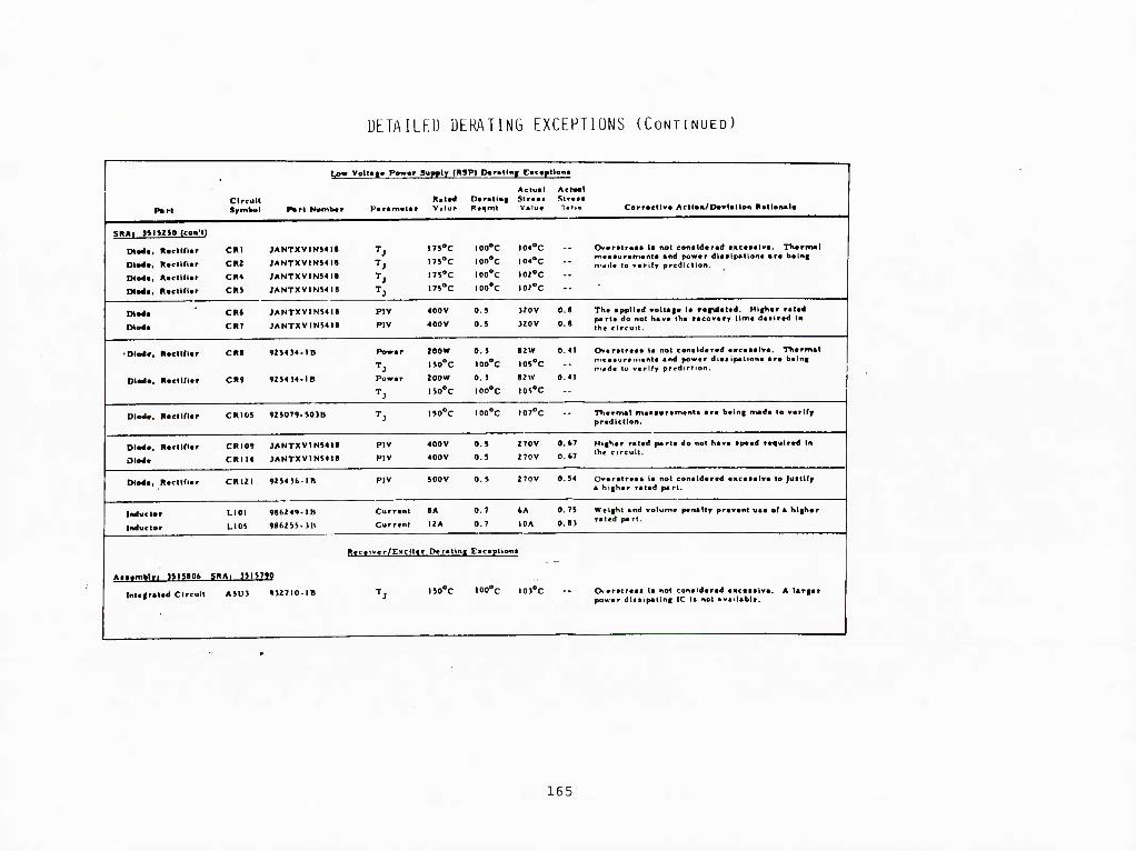
DETAILED DERATING EXCEPTIONS (CONTINUED)
P»rl Circuit Srtnkvl
Uow Volt*|« Pewor Suprlr (RSPI Doratlng Cacaptlona
Corrscllv* Acll«ii/I>«vUtlon RalloiMl* Port Numbor Paramolor Ratod Vilur
Da rating Actual Slraaa Valua
Actoal Slraaa nalia
SRAi HIJIJO Icon'l)
CRI
CR2
CR4
CRJ
JANTXVIN»<I«
JANTXVIN51H
JANTXVIN5HH
JANTXV1N541I
IT5°C
ni°c 175-C
l7i°C
lOO'C
loo'c
IOO°C
loo'c
I04''C
I04'*C
102''C
lOZ'C
-- Ov«rftr««« It not conildvrad tacaailva. T>tarmal m«a*ur«m«nta and power ditflpatkona ara baln| M'^ilr to verify prediction.
Oiotm.
ItoclKUr
Roctldor
Hocllllor
Roctldar
Diod* CRT
JANTXVIN54H
JANTXV1N54ia
PIV
PIV
400V
400V
0.5
0.5
320V
320V
O.B
O.B
The applied volUge la refulated. Hl|h«r rated part* do not have the recovery time deelred )n the circuit.
■Dlo4<.
Olo4t.
Roclirior
RoclKlar
CR>
cnt
4294S4-IB
92J4J4-IB
Powor
Power
200W
i»o°c 200W
iso'c
0. J
100°C
0. J
100°C
I2W
I05°C
»2W
105''C
0.41
0.41
Overatreae la not conalderad eEceaaive. T>t«rmal n.ea.ure.n.nia arnl power di.aipationa are b.ln| ni«de to verify prediction.
Olo4<, Roclirur CRIOJ 925079.50JB Tj lio'c loo'c I07°C -- Ttiermal meaauramenta are beln| mad* to verify
prediction.
RoctlCUr CRIO»
CRIM
JANTXVINi4ll
JANTXViNi4ie
PIV
PIV
400V
400V
0.5
0.5
270V
270V
O.fcT
O.t?
Higher rated parta do not have apeed required In the circuit.
Dlodt, Roctlflar CRI2I 92S4)b-IB PIV 500V 0.5 270V 0.54 Overatreaa la not conaldared eKceaalve to Juatlfy a higher rated part.
Inductor
Inductor
LIOI
LIOS
986249-18
98f>2iS-)B
Currant
Currant
>A
I2A
0.7
0.7
6A
IDA
0.75
O.B)
Weight and volume penalty prevent uae of a higher rated part.
Aiftmblr . J515106 SRA, J5IJ7M
Rccai.ar/E.cltt r Darallnl
iso'c
Cacaptiana
loo'c lOl'c -- CK-eratreaa la not conaldared eMceealve. A largar power dlaaipating IC la not available.
Intcgrolod Circuit A5U3 9)27I0-IB
165

F-18 PARIS CUNTKOL SIAIUS
PART TYPtS
761 APPROVALS
2 LlhlTbU APPROVALS
11 RLPLATLD APPROVALS
11 AT NAVY
0 IN-PROCESS
3 RLJLCIION-RLPLACL MIL PART
17 REJLCTION-DATA/APPLICATION
48/23 EXCLUDEU/ULLLTLIJ
87b TOTAL PART lYPES REOUESltlJ REQUIRING 2.028 TRANSACTIONS
45/13-12

ELKCTROSTATIC SKNSITIVfc; IJKVICbJ (ESD) CONTROL PROGRAM
Use ot digital systems and state-of-the-art components for the K-l» avionics systems,
and the rapid development ot new technology components required a method to mark and identity
ESD components and their next higher assemblies. The basic requirements were incorporated
into the radar procurement specification in 1978 to provide a means to mark and identify
the radar ESD items.
MCAIR's internal process specification was approved for use in February 1979 with a
special purchase order condition issued to the supplier to identify packaging instruction
for ESU components and next higher assemblies.
All radar ESU components and their next higher assemblies have been integrated into
the MCAIR ILS data requirements and support functions to identify the packaging, test, and
handling requirements tor the Navy. These initial requirements were imposed on our supplier
to assure that the reliability of the radar will not be compromised due to degraded devices
or latent failures resulting from ESU damage.
45B/7-3
168

bLbCIKUSTAIlC SLNS111VL DLVICL (bSU) CUN1KUL PKUGRAN
MARKING ANIJ 1 UtNTl (-ICAf I UN UF bSU CUNPUNbNTS ANIJ NbXT HlGHbK
ASSbMBLY KbyUlKbMbNiS 1NLIJKHUKAI blJ INIU b/A-18 AVlUNlL
PRUCUKbMbNlS (1978)
iNlbKNAb PRUCbSS SPbC1bICAI1 UN APPRUVbU bUR USb Al NGAIK
(PS ■mll'^ UATbU FbH. 1979. RbV. A ISSUblJ NUV 1982)
PACKAGING INSTRUCTIUNS ISSUbD UNDbR SPbCIAb PURCHASb URDbR
CUNDIllUNS (1979)
IIJbNIIblCATlUN Ub bSlJ LUMPUNbNIS AND NbXI HIGHbR ASSbNHblbS,
PACKAGING. IbSI, AND HANDbiNG RbUUlRbMbNIS INCURPURAlbU iNlU
THb IbS SUPPURl bUNClIUNS bUR NAVY SUPPORT
4V13-7
16 9

RIIILT-IN-TF.ST
RFOIIIRF.nEMTS
FAULT nFFFCTinM
FAULT ISnLATinN (TO WRA)
FALSF ALARM RATF
PFRinnic INITIATED
TFSTS inPLFMFHTFIl 106
« MINUIAL TLST-HNLY CmiPONFNTS
• PROGRESS IVF TEST FLOW
•» CAPABILITY FOR SRA LEVEL FAULT ISOLATION
521
'lSA/17-fi 170

BIT REQUIREMENTS
PERIODIC BIT (P-RIT) , •
DETECT >90Z OF FAULTS -- NOT DETECTED <10%
ISOLATED >907„ OF FAULTS DETECTED -- 81Z DETECTED AND ISOLATED
DETECTED - DETECTED AND ISOLATED -- DETECTED BUT NOT ISOLATED <9% -
INCORRECT ISOLATION <1% OF DETECTED AND ISOLATED -- <.81% INCORRECTLY ISOLATED
P-RIT AND INITIATED BIT (I-BIT)
DETECT >9n — NOT DETECTED <2%
ISOLATE >99^ OF FAULTS DETECTED -- >97% DETECTED AND ISOLATED
DETECTED - DETECTED AND ISOLATED -- DETECTED BUT NOT ISOLATED <2%
INCORRECT ISOLATION <!% OF DETECTED AND ISOLATED - <.97% INCORRECTLY ISOLATED
45A/15-n 171

BIT DESIGN
A general block diagram of the radar subsystem is shown on this chart. The radar
equipment is made up of five major WRAs. There are the Radar Data Processor (RDP), the
Radar Signal Processor (RSP), Receiver/Exciter (R/E), Transmitter (XMTR), and Antenna (ANT),
The Radar Data Processor contains the general purpose computer and the Low Voltage
Power Supply (LVPS). The data processor manages the entire radar, controls the modes,
executes BIT and contains all the nonvolatile memory for the radar. The data processor
controls all communication with the Mission Computer through the avionics multiplexer (A-
Mux), and it communicates to the remainder of the radar through two radar multiplexer (R-
Mux) channels, one to the RSP and the other to the remaining radar units.
The RDP is the first unit tested in IBIT and it is then used to test each of the
succeeding units which lie in the path of radar data flow. The low voltage power supply
section of the RDP is designed to remain on under all safe operating conditions and failures.
This is done to permit BIT to operate and find the system failure. If the RDP is inoperative
because of some essential LVPS failure, the fault indicator in the RDP is automatically set.
The Radar Signal Processor (RSP), which is tested next, is a high-speed digital
processor whose architecture and organization have been optimized for the radar signal
processing task. Its programs are loaded from the RDP. The core of the machine is tested
by loading in test data and programs, operating them and having the RDP evaluate the results.
In addition, the RSP input/output circuits, which interface with units other than the RDP,
have self-test capability to verify the RSP control over the units and the RSP ability to
receive data from them correctly. The main interface of this type is with the Receiver/
Exciter,
45B/B-7 ^"^2

BIT DESIGN
XMTH
BIT -.
TAR06T r ^ II,, BIT SOFTWARE ALLOCATIONS CALIBRATES 3.755 P BIT L480 I BIT 25.501
TOTAL DISC WORDS 30.736
IN ADDITION BIT INCLUDES ABOUT 450 BIT MICRO-INSTRUCTIONS WHICH RESIDE IN THE RDP IOC AND PROMS
GENERAL RADAR BLOCK DIAGRAM
173

BIT DESIGN (Continued)
The Receiver/Exciter unit, which is tested after the RSP, provides the RF drive to the
transmitter, receives two channels of received RF from the Antenna and performs RF, IF and
analog signal processing and A/D conversion. The tests of the Receiver/Exciter utili:;^e
signals derived from the Transmitter Drive, which are inserted into the Antenna, where the
signals split into each of the receiver input channels. These test signals are processed
through the Receiver and then evaluated by the previously tested RSP and RDP. In the
performance of these tests the Antenna RF processing is also tested.
The Transmitter is tested mainly by turning it on and having it radiate into a dummy
load during IBIT. It is also monitored by PBIT during tactical operation when it radiates
out the antenna. -
The antenna servo function is managed completely by the RDP. The servo tests consist
largely of exercising the servo functions and having the RDP monitor and evaluate the
results .
The test building block approach starts with the self-tested RDP and tests additional
functions one at a time. VJhen a function passes its test, it is used to test the next
function. This process adds a minimum of test hardware, permits more gualitative testing
than added special-purpose hardware and adds least to cost, weight and failure rates.
The test data are evaluated to isolate faults to the defective WRA, and the results are
made available to the Mission Computer.
45B/8-8
174

BIT IMPLEMENTATION
• CALIBRATES RFI VFO A/U BIAS FMK PHASE AND GAIN ZERO RANGE
• EXECUTED PERIODICALLY DURING TACTICAL OPERATION
• IN GENERAL A SIGNAL IS INJECTED INTO THE FRONT END OF THE SYSTEM AND THE DOWNSTREAM RESULTS ARE MONITORED AND SAVED FOR LATER USE BY THE PROCESSORS N COMPENSATING FOR TOLERANCE BUILD-UP AND ENVIRONMENTAL EFFECTS •
• THE RESULTS Of THE CALIBRATIONS ARE USED BY PERIODIC BIT TO PROVIDE AN INDICATION OF EN -TO-ENIJ SYSTEM OPERATION AND TO INDICATE MAJOR MALFUNCTIONS AND OUT-OF-TOLERANCE CONDI I IONS
• THE CALIBRATES DO NOT PROVIDE FAULT ISOLATION
895 RSP INST - DISC WORDS (RSP) 2685
1070 RDP INST - DISC WORDS (RDP) 1070
TOTAL 3755
175

BIT INPLENENTATION
PERIODIC BIT EXECUTIVE ANTENNA TRANSMITTER
R/E RDP RSP
• EXECUTED PERIODICALLY DURING TACTICAL OPERATION
• THREE TYPES OF PERIODIC TESTS PERFORMED: (1) BACKGROUND TESTS - COMPOSED OF FIRMWARE AND SOFTWARE ROUTINES WHICH TEST THE RDP
WHILE IT IS NOT ACTIVELY ENGAGED IN THE EXECUTION OF THE TACTICAL PROGRAM
(2) WRA I/O TESTS - CONSISTS OF A SERIES OF INTERROGATIONS WHICH ARE PERFORMED ON EACH WRA AS IT IS BEING SERVICED BY THE TACTICAL SOFTWARE. I.E.. R-MUX SERVICING OF THE ANTENNA, TRANSMITTER AND R/E AND RSP I/O SERVICING
(3) EVALUATION OF CALIBRATION RESULTS
• P BIT (INCLUDING THE RESULTS OF THE CALIBRATIONS) DETECTS 90% OF THE SYSTEM FAILURES AND ISOLATES 90% OF THESE TO THE WRA
1480 RDP INST - 1480 DISC WORDS
43B/8-28
176

BIT IMPLEMENTATION
INITIATED BIT SUPERVISOR (RDP) R/E EXECUTIVE (RSP) ANTENNA RDP TRANSMITTER RSP
INTERRUPTS TACTICAL OPERATION AND USES A BUILDING BLOCK APPROACH WHICH TESTS ADDITIONAL FUNCTIONS ONE AT A TIME
THE RDP IS TESTED FIRST USING FIRMWARE AND SOFTWARE SELF-TESTS
THE RSP SELF-TEST IS THEN PERFORMED UNDER THE SUPERVISION OF THE RDP
THE R/F IS THEN EXERCIZED AND TESTED BY THE RDP AND RSP
THE ANTENNA SERVO IS EXERCIZED AND ITS RESPONSE EVALUATED BY THE RDP
THE TRANSMITTER IS TESTED BY MONITORING ITS OPERATION INTO A DUMMY LOAD DURING BIT AND BY ADDITIONAL QUALITATIVE RF TESTS UTILIZING THE R/E AND RSP
I BIT DETECTS 98^ OF THE SYSTEM FAILURES AND ISOLATES 99% OF THESE TO THE WRA
5.540 RSP INST - DISC WORDS 16.620 8.881 RDP INST - DISC WORDS 8.881
TOTAL 25.501
45B/8-29
177

F-18 RADAR BIT DEVELOPMENT PROGRAM
The F-18 specification imposed NAVAIR document AR-10 (Maintainability of Avionics
Equipment and Systems). The primary requirement within AR-10 is BIT fault detection and
isolation. This was added to the radar procurement specification as a design requirement.
Hughes was required to submit data items and perform tests to verify compliance. The first
was an analytical verification, based on WRA, SRA and component failure rate. It was
required to show that the design would detect and isolate to the required percentages.
The next step was to take a look at the early design through the initial BIT assessment,
Faults were inserted into an operational system (302) and only three test failures were
allowed for a test complete, all test failures above three require analysis, fix and retest.
The same type test was combined with the maintainability demonstration which will be
conducted later this year (1983).
Also, a BIT detection requirement was added to the reliability development test (RDT).
During the RDT, a failure of the BIT to detect a failure or occurrence of a false alarm
required an analysis and fix.
During the F-18 flight test program at NATC-PAX River, Maryland, BIT was evaluated on
those aircraft containing radar systems. This evaluation continued at VFA-125 (NAS-LeMoore)
with MCAIR and NAVAIR personnel working together to define problem areas. These evaluations
have resulted in additional improvements which are currently being evaluated by NAVAIR at
both NAS-LeMoore and MCAS-El Toro.
45B/7-9
178

F-I8 KADAK BIT UbVhLUPMbNl PKUGKAM
HIKM SPtCIFICATIUN KEQUIKtMtNTS BACKtU WITH PUKMAL DPMUNSTKATIUN
ANALYTICAL VLKIPICATIUN
INITIAL BIT ASSESSMLNl (IBA) ThS
ULVELOPMLNl CUMBINLU WI1H KLLIABILITY UtVELOPMENT TESTING
COMBINED MAINTAINABILITY AND BIT DEMUNSTKATlUN
DEDICATED SYSTEMS DEVELOPMENT AIKCKAFT
;N1EGKATED BIT SYSIEM DEVELOPMENT ON PULL UP AIRCRAFT
4^/8-19 179

APG-65 aUILT-IN-TEST (BIT) IMPLEMENTATION
Two types of BIT are implementeri into the APG-65 radar system: periodic and initiated,
Periodic BIT is automatically performed at timed intervals during normal system operation
and does not require operator participation. Initiated BIT is a more extensive test and is
commanded to start by the operator. This test may also require some operator participation.
Both types ot BIT are analyzed and tested.
Although the radar requirements are only to detect and isolate to the taulty WKA, the
system is capable of going beyond this to the SRA level. This is a potential which needs
further study.
liy
^^^ (^
\
'^^^ fo- 3(
1^ ̂ stiM^^^ 45B/7-2 180

APG-bb B U1LI-IN-I bS] IhPLbMLNIAl1 UN
1EST PUKING UPbRATION
PhklUUIC BIT
10b TESTS CUNUUCIEU
bXTLNSIVE SPECIAL 1bST PUK ISOLAIIUN
INIIIAIEI) BIl
321 lESTS CONUUCTEU
KEUUlKEhEN
CAPABIblTY
PUlbNllAb:
:SUbAlb lU WKA
SObAflUN 10 MANY SKAs
SUbAl I UN lU fiUKb SKAs
181

APG-65 BIT ANALYTICAL VKRIKICATION
MCAIR required the supplier to submit a BIT analytical verification data item on how
he proposed to mechanize his BIT architecture within the radar to meet the procurement
specification requirements. This data item was submitted early in the program and contained
sufficient information for MCAIR to assess the supplier's BIT design approach. This data
item is submitted for MCAIR approval and is used as a tool to guide the supplier in his BIT
design.
45B/7-8 -"-^^

APG-6b BIT ANALYTICAL VbKlFlCATlON
INCLUDES AS A MINIMUM:
• A UtSCKIPTION UF LQUIPRLNT AND BIT UPLKATIUNS. INCLUDING FUNCTIONAL BLOCK
DIAGRAMS, SOFTWARE FLOW DIAGRAMS, AND METHOD OF IMPLEMENTING Bll FOR EACH
EQUIPMENT FUNCTION
• ADVANTAGES THAT MAY BE GAINED FROM TESIS USING OTHER INTERFACING AVIONICS
• DESCRIPTION AND JUSTIFICATION FOR ANY BIT INHIBII OR SYSTEM INTERRUPTION
REQUIREMENTS DURING ORGANIZATIONAL MAINTENANCE OR IN-FLIGHT
• DETAILED DESCRIPTION OF BIT METHODS USED (MULTIPLEX TERMINAL TEST, TEST
DISPLAY, CANNED ItST CONDITION, ETC) AND RECOMMENDA I IONS FOR ADDITIONAL
METHODS IF DESIRED
• TECHNICAL JUSTIFICATION FOR NON-COMPLIANCE OF IN-FLIGHT (PERIODIC) BIT
PERFORMANCE ALONG WITH ACHIEVABLE LEVELS
45/13-S 183

BIT ANALYTICAL VbRlFlCAT IIJN (CnNTiNii E D )
• DESCRIPTION OH THE EQUIPMLNI'S ABILITY TO PROVIDE OUTPUTS FOR DISPLAY OF
DEGRADED PERFORMANCE _ __ -
• THE TIME REUUIKED 10 DETERMINE A GO OR NO-GO CONDIIION OF IHE EOUIPMENT
IN EACH OF IHE BIT OPERATING MODES
• A DETAILED LIST OF EACH SIGNAL (FUNCTION. PARAMETER. ETC) USED BY THE
EOUIPNENT TO DETERMINE AN EQUIPMENT FAILURE. ALONG WITH ITS APPLIED
ACCEPT/REJECT LIMIT AND EXCEED TIME CRITERIA
• THE RATIONALE FOR THE SELECTION "OF EACH ITEM IN ABOVE LIST
• A DESCRIPTION OF THE METHOD OF ADJUSTING THE ACCEPl/REJECT LIMITS AND
EXCEED TIME TOLERANCES FOR PKEPRODUCTION EQUIPMENT
• JUSTIFICATION FOR USE OF WRA FAILURE INDICATOR OTHER THAN THAT SPECIFIED
^b/13-b 185

APG-65 RADAR BIT DATA AT THE FLIGHTLINK,
The radar BIT design requirements were established and incorporated into the MCAIR
procurement specification. An important factor for developing the radar system's BIT was
data management. The BIT design was followed from the start of the program through a
sequence of tests and demonstrations which started with the analytical verification, initial
BIT assessment, test-analyze-and-fix, maintainability demonstrations, factory and field
data, and reliability demonstrations. The management of data accumulated during these
tests allowed MCAIR and the supplier to assess BIT performance and implement improvements
into the radar system BIT design.
The design of the radar BIT allows deployment of aircraft to remote sites with no
organizational level ground support equipment required for support of the radar. Rapid
fault detection and isolation coupled with ease of removal and replacement increased the
availability of the radar for flight. The potential of reducing test station loading could
be realized by taking advantage of the processing capability of the radar. MCAIR developed
an organizational level test set (AFTA—Avionics Fault Tree Analyzer) which can access the
radar's BIT fault data stored in memory. With the development of a fault tree for the
radar, SRA isolation is possible using the AFTA via the 1553 MUX BUS. On aircraft, SRA
isolation could result in reduced test station loading, improved WRA availability, and a
reduction in requirements for WRA spares.
As a result of the radar's digital processing capability a special relay mode is
provided for beyond BIT troubleshooting. This stored data can be called up on the digital
display indicators in the cockpit to assist the maintenance personnel to isolate faults
which were not detected or isolated by BIT.
45B/7-12
186

APG-65 RADAR BIT DATA AT THE FLIGHTLINE
ESTABLISH BIT nETECTIOM/ISOLATinN REQUIREMENTS
BIT DATA MANAGEnENT IS IMPORTANT FOR ASSESSING BIT PERFORMANCE
SHOP LOADS CAN BE REDUCED BY ISOLATING TO MANY SRAs
- AVAILABILITY IMPROVED
- DEPLOYMENTS TO REMOTE BASE SIMPLER
- POTENTIAL REDUCTION OF SHOP GSE
- REDUCTION IN SPARE WRA ASSETS
RADAR t
DISPLAYS t
MISSION COMPUTERS
1553 BUS
MAINTENANCE
MONITOR PANEL
AVION CS FAULT TREE ANALYZER (AFTA) MUX BUS GROUND ACCESS
- SPECIAL FAULT TREE ROUTINES
- SRA READOUTS
RADAR DATA ON THE MUX BUS (RELAY MODE)
• SPECIAL MESSAGES FOR WRA FAILS
• SPECIAL MESSAGES FOR MORE THAN 300 PIECES OF BIT DATA
• DATA STORED IN NONVOLATILE MEMORY TO REFLECT FLIGHT DATA
OTHER EQUIPMENTS
187

AP6-65 RADAR
BIT DATA AVAILABLE TODAY
COMPUTER
1553 BUS
RADAR MAIN MONITOR PANEL WRA FAIL
DATA IN RADAR NONVOLATILE MEMORY:
ACCUMULATED PERIODIC-BIT MATRIX:
INITIATED BIT MATRIX:
OPERATIONAL BIT MATRIX:
45A/9-8
GROUND ACCESS
FAULT IKEES DEVELOPMENT
DISPLAYS
ALL P-BIT EVENTS DURING FLIGHT
LAST I-BIT MATRIX STATUS OR CURRENT STATUS IF CLEARED
LAST MATRIX FROM TURN-ON TEST SEQUENCE
A) RELAY MODE - GROUND USE
- CALLS UP FAIL INDICATIONS IN ANY AVAILABLE MATRIX
- PROVIDE RADAR ISOLATION ASSESSMENT
- HISTORY AND CURRENT STATUS
B) MEMORY INSPECT
- ADDRESS ANY MEMORY LOCATION
- ADDRESS VOLATILE MEMORY
- CURRENT STATUS
189

MAN UFACTFI RING

MNUFACTUKING
STKbSS SCKtliNING
PAlLUKh KtPUKTlNG AND CUKKtCllVh ACIIUN
INTbGKAltl) CUKkbCllVb ACTlUN PKUGRAM (ICAP)
COS! KLIJUCTIUN
^3/8-5 191

PRnPIICTinN CONTROLS TO ENSURE APG-65 RELIABILITY
• COMPONENTS 100^ TEST-AT-TEMP (ICs & HYBRIDS)
PIN TEST (CAVITY DEVICES)
LEAK TEST (ICs & HYBRIDS)
SUPPLIER SURVEILLANCE
MINIMIZE DEFECTS BEFORE STARTING ASSEMBLY
» ASSEMBLY SCREENS SRA. WRA. BURN-IN CULL ASSEMBLY DEFECTS & RESIDUAL PART DEFECTS BEFORE THE COUNTING STARTS
• REPAIR RULES . PIECE PART REPLACEMENT
FAULT VERIFICATION
ASSURE UNIFORM SCREENING
ACCURATE CAUSE DETERMINATION
RESOLVE INTERMITTENTS AND "UNKNOWNS" BEFORE THE COUNTING STARTS
• FAILURE DATA EXACTLY WHAT. EXACTLY WHERE
AUTOMATION
PROGRAM IDENTIFICATION BY ANALYSIS OF VALID STATISTICS
EVALUATION OF SCREENS
RAPID RESPONSE. REDUCED ERROR RATE. REDUCED COST OF ACQUISITION
• MANAGEMENT
45C/1-8
QUALITY REVIEW BOARD MANAGEMENT REVIEW OF QUALITY CORREC- TIVE ACTION PROCESS
193
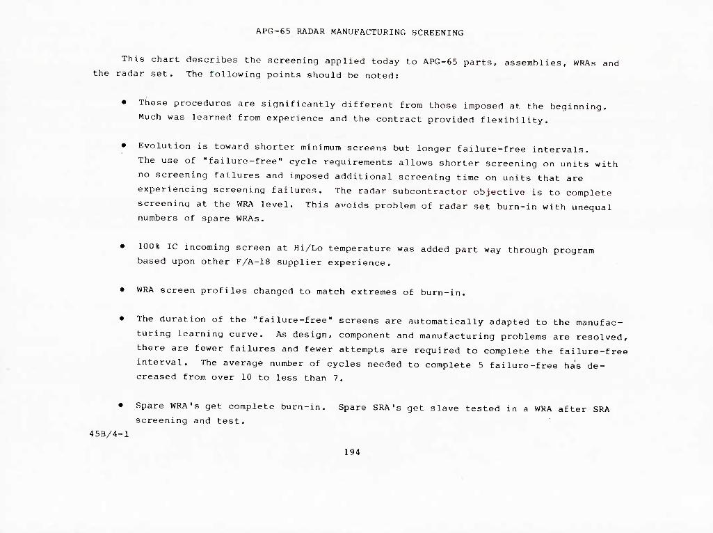
APG-65 RADAR MANUFACTURING SCREENING
This chart describes the screening applied today to APG-65 parts, assemblies, WRAs and
the radar set. The following points should be noted:
• These procedures are significantly different from those imposed at the beginning.
Much was learned from experience and the contract provided flexibility.
• Evolution is toward shorter minimum screens but longer failure-free intervals.
The use of "failure-free" cycle requirements allows shorter screening on units with '
no screening failures and imposed additional screening time on units that are
experiencing screening failures. The radar subcontractor objective is to complete
screening at the WRA level. This avoids problem of radar set burn-in with unequal
numbers of spare WRAs.
• 100% IC incoming screen at Hi/Lo temperature was added part way through program
based upon other F/A-18 supplier experience.
• WRA screen profiles changed to match extremes of burn-in.
• The duration of the "failure-free" screens are automatically adapted to the manufac-
turing learning curve. As design, component and manufacturing problems are resolved,
there are fewer failures and fewer attempts are required to complete the failure-free
interval. The average number of cycles needed to complete 5 failure-free has de-
creased from over 10 to less than 7.
45B/4-1
Spare WRA' s get complete burn-in. Spare SRA's get slave tested in a WRA after SRA
screening and test.
194

MANIIFAr.lDKlNG SCKbbNING
TEMPERATURE
RATE OF CHANGE
CYCLES
DURATION
ON-TIME
FAILURE-FREE
TEST-AT-TEMP
VIBRATION
DURATION
FAILURE FREE
PARTS
1 L tTzm ijmjmniijuj|L|yi^)jlijjiiij^ij^
65°C TO -H50°C
15°C/MIN
10
0.5 HRS
NONE
N/A
100%
NONE
N/A
N/A
SRAS
-60°C TO -^95°C
15°C/MIN
46
24 HRS
NONE
N/A
FUNCTIONAL TEST AT ROOM TEMP
NONE
N/A
N/A
WRAS
55°C TO -^55°C
15°C/MIN
12
24 HRS
13 HRS
3 CYCLES
100%
6() RMS RANDOM
20 MIN
20MIN
BURN-IN
54°C TO -^46°C
5°C/MIN
5
35 HRS
25 HRS
5 CYCLES
100%
2c)SINE
10 MIN/HR
COMBINED WITH TEMP
195

4b/8-6
F-18 SCREENING PKUbRAI
EFFECTIVENESS DATA: INDUSTRY/GOVERNMENT STUDIES
NAVY MANUFACTURING SCREENING PROGRAM: NAVMAT P-9i|92
TEMPERATURE
RANDOM VIBRATION
F/A-18 IMPLEMENTATION: • HARD REQUIREMENTS AT RADAR SYSTEM LEVEL
• POTENTIAL SUPPLIER PROGRAM WAS A MAJOR PART OF SOURCE
SELECTION
- LOWER LEVEL SCREENS CONTROLLED VIA SUPPLIER DRAWINGS
- HEAVY SUPPLIER INCENTIVE TO IDENTIFY PROBLEMS EARLY
IN THE TEST CYCLE
- FLEXIBILITY TO RAPIDLY IMPROVE SCREENING TECHNIQUES
(EARLY SYSTEM LEVEL TEST TRANSMITTER PROBLEMS '
RESULTED IN IMMEDIATE SCREEN CHANGES - RESOLVED
PROBLEMS AT LOWEST LEVEL)
196
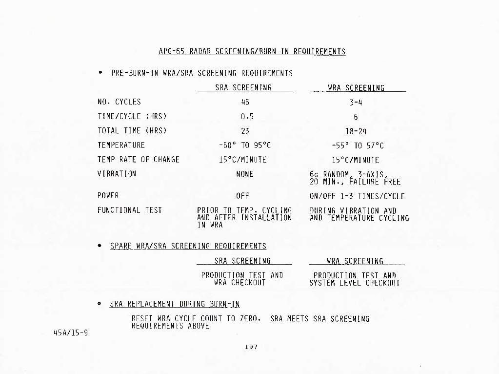
APG-65 RADAR SCREENING/RURN-IN REQUIREMENTS
• PRE-BURN-IN WRA/SRA SCREENING REQUIREMENTS
SRA SCREENING WRA SCREENING
NO. CYCLES ^16 3-i,
TIME/CYCLE (HRS) 0.5 6
TOTAL TIME (HRS) 23 18-24
TEMPERATURE -60° TO 95°C -55° TO 57°C
TEMP RATE OF CHANGE 15°C/MINUTE 15°C/MINUTE
VIBRATION NONE 6G RANDOM. 3-AXIS. 20 MIN.. FAILURE FREE
POWER OFF ON/OFF 1-3 TIMES/CYCLE
FUNCTIONAL TEST PRIOR TO TEMP. CYCLING AND AFTER INSTALLATION
DURING VIBRATION AND AND TEMPERATURE CYCLING
IN WRA
SPARE WRA/SRA SCREENING REQUIREMENTS
SRA SCREENING
PRODUCTION TEST AND WRA CHECKOUT
WRA SCREENING
PRODUCTION TEST AND SYSTEM LEVEL CHECKOUT
'45A/15-9
SRA REPLACEMENT DURING BURN-IN
RESET WRA CYCLE COUNT TO ZERO. REQUIREMENTS ABOVE
SRA MEETS SRA SCREENING
197

TRANSMITTER SCREENING PROFILE
1-57OC + 3
COOLANT
TEMP AT
INLET TO
TRANSMITTER
ROOn TEMP
-55OC + 3
START
■180 + 5 MIN.
■laOif) fllN.- \
END
198

AIR COOLED WRA SCREENING PROFILE
+55°C + 3
-37OC ± 3
-55°C±3
CHAMBER AIR
TEMPERATURE -120 +5 Miri-
-ISOMIN-nOM
OFF
START
350 +5 MiN
CnOLlMG AIR PRESSURE. Ill KICI'.ES OF H2O. AT HOT PHELL:
END

45A/15-8
APG-65 FAILURE nONITOKING/CORRELATIUN/CORRECTlVE ACTION SYSTEM
NEEDS:
• THUROUGH DATA SYSTEM FUR FAILURES AT ALL LEVELS UF
MANUFACTURING CYCLE
• RAPID FEEDBACK TO PROGRAM RELIABILITY/QUALITY ASSURANCE
CONTROL POINT
• IDENTIFICATION OF AND TRENDS CORRELATION WITH FIELD DATA
TO IDENTIFY RAPID CORRECTIVE ACTION
IMPLEMENTATION: '
• AUTOMATED DATA ENTRY/RETRIEVAL SYSTEM FOR ENTRY AT
MANUFACTURING STATIONS FROM SRA TEST THROUGH SYSTEM
TEST
• DATA MANAGEMENT PROGRAMS TO CORRELATE AND PRESENT DATA
FOR PROGRAM ACTION
201

CLEAR (CLOSED-LOOP EVALUATION & REPORTING) SYSTEM
Evolution of the CLEAR system began with the F-15 Eaqle program around 1970. The
reliability (R), maintainability (M), and quality (0), requirements for that aircraft were
more stringent and required more data to be collected than any previous programs. As a
result, a team was assembled and the CLEAR system was developed and implemented on the
F-15 program.
The ability of the system to supply the data needs of all three disciplines, R, M, and
0 was given prime consideration, since up to that time each discipline was inputting and
processing essentially the same data in different systems. Uniform reporting of future
projects and the elimination of duplication of effort were major design goals.
In 1976 MCAIR was awarded the contract by the Navy to develop the F/A-18 Hornet
Aircraft. A primary requirement of the Hornet program was to provide an aircraft with a
significant reduction in LCC over current Navy systems. Intensified corrective action
programs, expanded failure reporting coverage and R and M demonstrations dictated the need
for some improvement in the CLEAR system. The improvements primarily involved modifications
to the reporting procedures along with a redesign of the on-aircraft (organizational level)
reporting forms. These changes enabled CLEAR to more closely emulate the Navy 3M (Maintenance,
Material, Management) system.
45B/8-11
202

4b/9-7
CLEAR (CLUSI:D-LUUP LVALUATIUM & KbPUKTING) SYSTEM
• MCAIR SYSTEM FOK COLLECTING NON-CONFORMANCE, MAINTENANCE AND
FAILURE INFORMATION WITH COMPUTER REPORTING FOR ANALYSIS AND
PRODUCT UPGRADING
• DEVELOPED FOR F-lb AND IMPROVED FOR F-18 USAGE
' / SUPPLIER TESTS
/ MCAIR BENCH & QUAL TESTS
/ PILOT SQUAWKS
/ ON/OFF AIRCRAFl REPAIRS
/ SUPPORT OF CUSTOMER TESTS
203
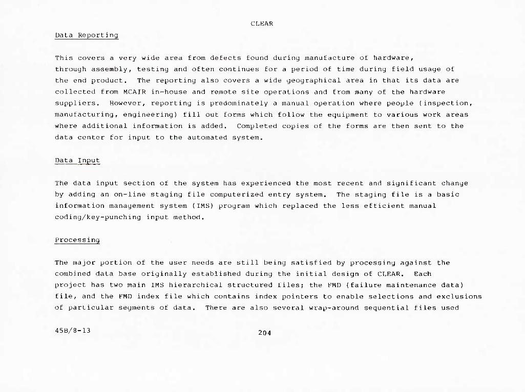
CLEAR
Data Reporting
This covers a very wide area from defects found during manufacture of hardware,
through assembly, testing and often continues for a period of time during field usage of
the end product. The reporting also covers a wide geographical area in that its data are
collected from MCAIR in-house and remote site operations and from many of the hardware
suppliers. However, reporting is predominately a manual operation where people (inspection,
manufacturing, engineering) fill out forms which follow the equipment to various work areas
where additional information is added. Completed copies of the forms are then sent to the
data center for input to the automated system.
Data Input
The data input section of the system has experienced the most recent and significant change
by adding an on-line staging file computerized entry system. The staging file is a basic
information management system (IMS) program which replaced the less efficient manual
coding/key-punching input method.
Processing
The major portion of the user needs are still being satisfied by processing against the
combined data base originally established during the initial design of CLEAR. Each
project has two main IMS hierarchical structured files; the FMD (failure maintenance data)
file, and the P'MD index file which contains index pointers to enable selections and exclusions
of particular segments of data. There are also several wrap-around sequential files used
45B/8-13 204
CLEAR FORMS ~. ~-~^>. ■ FlIINT KICOKD WOKKSMIET -5^ jn^
. t«t ■* *\I«-T1II "■ iirmK—iiT Utn>«i ,^«
LiMjiuii > jm n nn \
C(.IAM rOMM ■ MM!
HAINTlNAHCt -NONCONKMMANCI IKOtD
1 t J.....^.. .I... "'
=r"
I ta*t.*>l m» • ft«tt
B„_"R
H^JiHJa" ilJWWJt^
TTmnm ^u.-^pu
3B "■■ ■ ^p«t
□ t.*^^. o — D —
U-tJAUmvv-iy- « i
rn uuvuvn?
fc^
\n»* mtr
205
r'^'^^

CLEAR REPORTING DURING FLIGHT TESTING
The reporting cycle begins when the pilot worksheet, CLEAR form A, is filled out.
Included on the form are certain facts about the flight, take-off times, landing times and
so on. Also included is a list of "Squawks" encountered by the pilot during the flight.
After debriefing is complete the form A is routed to the inspection office where a
separate form B is prepared for each pilot squawk. This form is used to document all data
concerning the aircraft (organizational level) repairs. If the repairs can be made on the
aircraft without removing a unit for additional test and/or repairs, the form B is completed
stamped-off, and routed to the data center for input to the system.
If it is necessary to remove a unit for test and/or repair, a form C is initiated to
record the off-aircraft (intermediate level) test and repair data. This form is attached
to the hardware and both are taken to the bond room for disposition of the hardware. The
hardware and a copy of the form are then sent to the test/repair area. Here one of three
things normally happens. The equipment checks good, minor problems are found and repaired,
or the failure is confirmed but cannot be repaired locally. The results of the test/repair
are recorded and the hardware and form are returned to the bond room. Good equipment will
be returned to the aircraft or stores, and defective equipment is returned to the supplier
for repair. ■
45B/8-14 206

USE OF CLEAR FORMS DURINGrfLIGHT TESTING
FOR DELAYED HEPAIRS OF FLT/GND SQUAWK:
• ORIGINAL FORMS IS CLOSED • FORM BDUn IS INITIATED
WHEN REPAIRS ARE MADE • NOTE 1 PROCEDUnE APPLIES
WHEN EQUIPMENT SENT TO SUHPllER FOR REI'AIH
• SUPPLIER COMCLETES C0PY4 0FCIEAII FORMC Pen DATA ITEM OOl 0?
- AND- • SUPPLIER COMPLETES *
FAILUIIE ANALYSIS/CORRECTIVE ACTION REPOIITPER DATA lUM E 14 09
FLIGHT SQUAWK
1 GROUND SQUAWK
CLEAR FORMA
I CLEAR FORM B/FR
RECORDED ON QPIS: • SERVICING SUPTORT
• PHASED MAINTENANCE • SCHEDULED
MAINTENANCE
CLEAR FORM B/MNR \z
CLEAR FORMC
I
NOTE 1 IF REPAIRS MADE ON AIRCRAFT
y • CLEAR FORM B COMPLETED
IF REPAIRS REQUIRE EQUIPMENT REMOVAL • CLEAR FORMS COMPLETED • CLEAR FORMC INITIATED
BOND nuuM
EQUII'MCNT ANO CLEAR FORMC COPY 3 TO
REPAIR AREA
IF UNIT CHECKS GOOD OR REPAIRS COMPLETED INHOUSE: • COMPLETE COPY 3 (BENCH TEST AND REPAIR! • RETURN (EQUIPMENT ANO FORMI TO BONO ROOM
-OR-
IF REPAIRS ARE NOT COMPLETED INHOUSE: • COMPLETE COPY.3 (BENCH TEST) • RETURN (EQUIPMENT AND FORMI TO BOND ROOM
207

ICAP
The MCAIR integrated corrective action program committee has been in operation on the
F-18 radar since program inception. This team meets bi-weekly and consists of representa-
tives from the various disciplines involved in assuring the system meets it reliability,
maintainability, and quality requirements. During the course of this program many problems
have been reviewed. Sixty two of these were of sufficient magnitude to require formal
documentation and reporting. Of these 62 problems, 6 are now (1983) open and being monitored,
45B/8-30
208

INTbGKATLD CUKKLC1IVE AC1lUN PROGRAM (ICAP)
• OBJECTIVE: TO IMPLEMENT EARLY CORRECTIVE ACTION HASED ON REVIEW
Oh HA I LURE IJATA
• TEAM MEMBERS: ELECTRONIC ENGINEERING
KAUAR LAB
MANUEACTURING PLANNING
RELIABILITY
OUALllY ASSURANCE
MAINTAINABILITY
HUGHES REP AT MCAIR
• PREPRODUCTION: REVIEW FAILURE DATA FROM TESTS AT HUGHES (BURN-IN.
RELIABILIIY DEVELOPMENT. ENGINEERING TESIS). FLIGHT
DEVELOPMENl (PAX RIVER). AND EQUIPMENT TESTS AT MCAH
• PRODUCTION: REVIEW FAILURE DATA FROM TEST FLIGHIS AT MCAIR AND NAVY
FLEET FAILURES
• ICAP PROBLEM STATUS. F-18 RADAR
- TOTAL PROBLEMS IDENTIFIED - bl
- OPEN PROBLEMS - b
209

INTEGRATED CORRECTIVE ACTION PROGRAM
lufj '•mMrMi.m<Lt,.im w,r>ma
FAILURE REPORTS
»-
FAILURE REVIEW MANAGEMENT REVIEW
SYSTEM TEST MFG. TEST/INSP COMPONENT TEST
FRB - ENGINEERING QRB - MANUFACTURING
HAC/MCAIR I CAP i \ ^
-»-T
CORRECTIVE ACTION
ENGINEERING/ MANUFACTURING *-?
0 PROGRAri MANAGEMENT PARTICIPATION
0 FORMAL INSTRUCTIONS
L I ■ifnaHi.Tvrii 'WTJg..t.j'!Hi«t.!i,ijw!.. ''■i',^"-.»^-> >..,T.»^jr"".».w.''■■■j'lL'jwi.wiJLi.M. .. m.. J.L-'.'-T^.'J Will.-J-"»^I-IIL11- ■Jll^l. UL'-...IU»f "V!m
210

MCAIR/3UPPLIER i.\iVco.^ATZD COr-FJECTIVE ACTSOIM PROGRAM OPEN PROBLEM STATUS
P.8. NO. 7t-H7QQ52
P/N iwsnnn NOMENCLATURE EADAK 3T3ID<
46 o*Ti PLC B2 fkot ci-i
PROB REPORTED PROBLEM DESCRIPTION
FIELD FAILURES PRIORITY
ACTION PENDING TO CLOSE PROBLEM
NO BY DATE AGENCY DESCRIPTION DUE COMPLETED
•il MCAIR Ol-U-82 Trniiiialtter CHtlng Ruptured. I (Could affect all ays.)
MCAIR RCP COP J82 ssnt to MCAIR.
MCA 1 R
IIC.AIR
)6-02-82 10-21-82
LVPS 4A22 mid 7A1. MCAIR haa enperlenced (17) *A22 and (21) 7AI nonconfoTBancea fro« Jan thru K/iy 1982.
HUCHKS
MCAIR
MCAIR
HAC Englnesrlng InTestigstlon I.VPS 7AI is now ICAP 55-A. LVPS ♦A22 Is now ICAP 55-B.
•tb MCAIR 08-05-82 High Voltaga Pwr. Supply WA 1A2 has ntneroua fallurea at LrHoore and St. Loula. Specific failures on (5) SRA 1A2A2, P/N 928883-18 Tronslstori
Approx. 14 fallur. Jan thru July 82
8
HUCHIH HAC Engineering Inyestlgatloa
57 MCAIR 08-27-82 StIcVtng (075) Racka caused by gun gaa residue.
Approx. 12 fallur to data
S
nUGHRS Rnglneerlng oa hold to rs-erslusts design for weight redaction.
5B HCAIR 08-27-82 Tranaralttar dropa through guide ralla. Guide ralla bend down allowing TX. to fall off the guide rails during reaovsl.
Approx. 3rd fallu to data
e IIUCHRS Chsngs to strsngthsn rsUs
required. Evsluatlng other poealble designs to reduce weight. Change par ECR 803638I/ECA 489381.
59 MCAIR 09-15-82 SRA 2A7 Raf. OSC, P/M 3515820-XX la a low reliability Itea.
Anprox. • Id fallur. to date
s iniCHRS Engineering Inveatlgatlng.
60 MCAIR 09-15-82 SRA 2A10 Digital Module P/M 3575240-RX Is a low reliability Itea.
Approx. 15 fallur. to date
s IIUCHRS Rnglneerlng Investigs ting.
62 MCAIR 10-29-82 16K IC P/N 932864-OOlB low reliability Itea In Opt (3) radar eqiil p.
,\/prox. i6 SHA tallures to date
IIUCIIES
■
Engineering investigating.
• C <t»Ml !«■ V t J*H ttl 211

PROB NO.
8
9
10
11
12
13
14
15
MCAIR/SUPPLIER INTEGRATED CORRECTIVE ACTION PROGRAM PROBLEM STATUS HBwrun *5
».tjn 7*-870052 O^TE SOTjT '•^ ^*°- • PAGE
^^^^°°° NOMENCLATURE RADAR SYSTEM P/N
PROBLEM DESCRIPTION
REPORTED DATE
RESPONSIBILITY FOR
REPT81 CORRECTIVE FOLLOWUP ACTION
STATUS/ DATE
REMARKS
Motor Aop 3472426 Failures 1-22-9
Chi Sel Switch 259446 Failures 1-22-9
"XMTR-CAL" Fails (Pulse Spikes) 1-22-9
CAP. M39014/02-1419 Failures 2-05-9
Coolant Leaks § Xatr Inlet 2-06-9
Mareguide/array screws loosen 2-28-9
Interalttent 900Hi signal 2-28-9
Multilayer Board shorts & opens 3-21-9
Chain Reaction Failures 3-21-9
Breakage of Module Extractors 3-21-9
GTWT, P/M 259255 - Low Power 3-26-9
Coax Connect. Fatigue (3537479) 3-30-9
W/G Claap 918356 Failures 7-11-9
No Theraal Bond at Hybrids 7-11-9
Transistor 928B83-1B Failures 7-13-9
MCAIR
MCAIR
MCAIR
MCAIR
MCAIR
MCAIR
MCAIR
MCAIR
MCAIR
MCAIR
MCAIR
MCAIR
MCAIR
MCAIR
MCAIR
Hughes
Hughes
Hughes
Hughes
Hughes
Hughes
Hughes
Hughes
Hughes
Hughes
Hughes
Hughes
Hughes
Hughes
Hughes
CLD OCT 82 lBprove»ent8 Yla ECA 474386-lA.
CLD APR 80 laproveaents via CCPs 192, 230 4 242.
CLD APR 80 Design change (CCP083) I Oil, S/M 016.
CLD JAN 80 Mo action-investgtn neg-fails subsided.
CLD OCT 79 'O'ring Mt'l changed « Oil, S/M 016.
CLD OCT 79 Locktite on screws f 031, S/N 016.
CLD APR 80 031 flex cables redesigned % S/H 016.
CLD APR 80 Optical aids in use - Ongoing actions.
CLD OCT 79 No action - HAC feels design Is adequate.
CLD OCT 81 Stronger extractor Material I Set 055.
CLD APR 80 laproved design/asaeably techniques.
CLD JUM 81 Right-angle connector at Rack LET088.
CLD SEP 81 Caution note added to Tech Orders.
CLD DEC 79 Assy/lnsp laproveaents incorporated.
CLD APR 80 laproveBents via CCPs 175, 221 & 226.
212

MCAIR/SUPPLIER INTEGRATED CORRECTIVE ACTION PROGRAM
PROB NO.
16
17
18
19
20
21
22
23
24
25
26
27
28
29
30
PROBLEM STATUS
P.S.NO.
P/N
PROBLEM DESCRIPTION
74-870052
REPORT N0.__*5_ DATF WOV 82
PAGE
3525000 NOMENCLATURE RADAR STSTBt
REPORTED DATE
Cover Fastener kamy Separates 8-07-9
Semi-rigid W/G Asay Damage 8-08-9
Failure of Flex Cable Aasys 9-10-9
Non-constraint of Shld Wires 9-07-9
Module Ident Markings not Clear 9-19-9
Capacitor 910034-lB Failures 10-11-9
IC P/N 932775-lB Failures 11-21-9
IC 932749-lB Failures 1-21-0
Ant Conn Jackscrew Malnt Falls 12-17-9
Filter 930482/483 Failures 1-22-0
Tranaistor 928185-504B Failures 1-22-0
IC 932777-lB Failures 1-24-0
Fart Failures from Xatr Arcing 2-15-0
Oil Cover Fasteners Separate 2-05-0
Pantograph F/N 3537480 Problems 3-07-0
RESPONSIBILITY FOR
REPT& CORRECTIVE FOLLOWUP ACTION
STATUS/ DATE
REMARKS
HCAIR
MCAIR
HCAIR
MCAIR
HCAIR
MCAIR
MCAIR
MCAIR
MCAIR
MCAIR
MCAIR
MCAIR
HCAIR
HCAIR
HCAIR
Hughes
Hughes
Hughes
Hughes
Hughes
Hughes
Hughes
Hughes
Hughes
Hughes
Hughes
Hughes
Hughes
Hughes
Hughes
CU) APR 80 Improved faatener 9 Sat No. 024 (OFT II).
CLD APR 80 Deaign change (0CP167) 9 075, S/M 013.
CLD APR 80 Design changes via CCP13B/185 t ECA474347.
CLD FKB 80 Mfg. Planning for 041/681 revised Nov 79.
CLD APR 80 Mech. deaign change 9 Set 024 (OPT II).
CLD SEP 81 Improved capacitor-CCP 346/Set 055 (OPT 3).
CLD APR 80 lOOZ Screen 9 Rec Inap - Low t High Temp.
CLD APR 80 lOOZ Screen 9 Rec Inap - Low t High Temp.
CLD APR 80 Deaign change to slot bolts 9 031 S/N 027.
CLD JAN 82 Improved capacitor construetion-0/C 8133.
CLD HAR 80 Design change (CCP241) 9 Oil, S/M 027.
CLD APR 80 lOOZ Screen 9 Rec Inap - Low A High Temp.
CLD JUL 81 Deaign Change - CCP 196/241/278/298.
CLD APR 80 Improved fastener 9 Oil No. 027 (Opt II).
CLD JUL 80 Improvements initiated 9 Rack No. 015.
MAC 4I7*B mcv >I FC« 7tl 213

MCAIR/SUPPLIER INTEGRATED CORRECTIVE ACTION PROGRAM PROBLEM STATUS
74-«70052 P.S.NO.
P/N 3525000
REPC3RT Ma__jl5_ DATE - WOV 82 PAGE
NOMENCLATURE RADAR sTsrm
PROB NO.
31
32
33
34
35
36
37
38
39
40
41
42
43
44
45
PROBLEM DESCRIPTION
RESPONSIBILITY FOR
Rack Hdwe Ruat/Worn Harklnga
Pattern Fall of IC 932180-502B
Kqulpaent Soldering Defects
RaverBed 7A1C102-Dvg Error
Antenna Borealght Null Shifts
Pattern Fall of IC 932751-lB
Borealght Error Accua. 0/T
Antenna Scan buaper failures
JMTR Conn Jackacrew-Malnt Falls
Wire Damage Within 041/681 WRAs
Daaaged Rack Retaining Bolts
Coolant Fitting 05P08 Pops Off
Clocking of Connectors 4J3/7J6
Bad Shid Terainatlon-Oll Plugs
Coax Connection Fatigue - 01P08
REPORTEI DATE
^ REPT 8i FOLLOW UP
CORRECTIVE ACTION
3-11-0 MCAIR Hughes
3-18-0 Hughes Hughes
4-24-0 MCAIR Hughes
5-13-0 MCAIR Hughes
5-20-0 MCAIR Hughes
6-11-0 Hughes Hughes
6-13-0 MCAIR MCAIR
8-21-0 MCAIR Hughes
10-22-0 MCAIR Hughes
10-22-0 MCAIR Hughes
01-16-1 Hughes Hughes
01-22-1 MCAIR MCAIR
03-12-1 MCAIR Hughes
04-14-1 MCAIR Hughes
05-07-1 MCAIR Hughes 1
DATE REMARKS
CLO NOV 80 Screening checks at Rec Insp added.
CLD JUL 80 Transferred to ICAP Ho. 28.
CLD JUL 80 Reaedial Measures initiated 9 Sya Oil.
CLD JUN 80 Drawing error corrected.
CLD AUG 80 Mech design change to 3597823 § KqQ020.
CLD DEC 80 Circuit redesign - 16K RAH - at Sratea 060.
CLD SEP 81 laproved Mfg procedures & aligrasent tool.
CLD SEP 80 Mech design change 9 Sys 027.
CLD JAN 81 Mat'l change (lA2)-7/64 Jack8creirt-lA6/7.
CLD AUG 81 Protective tape added to wire bundles.
CLD JAN 82 Mech change - EO 27630 f Set 128.
CLD DEC 81 Various inproveaenta - See INCAP Rpt Ho. 34
CLU MAY 81 Retrofit Instructions 3624293 corrected.
CLD MAY 81 Planning/Inspection revised & OJT added.
CLD JUN 81 Autonatlc crimping tool at Rack LBM034.
MAC 417flB mcv 12 FCB Tff) 214

MCAIR/SUPPLIER INTEGRATED CORRECTIVE ACTION PROGRAM RCPoirrNo.. 41.
• «Mn 74-870052
ff 1 IX^ K^kBi . IT! %* ■ r~* ■ %^ X. ̂ HATF IWV 82 PAGE
p^ 3525000 NOMENCLATURE
BILITYFOR
RADAR SYSTKM
RESPONSI
PROB NO.
PROBLEM REPORTED p^p-^ g^ DESCRIPTION DATE poLLOW UP
CORRECTIVE ACTION
STATUS/ DATE
REMARKS
46 Contact B/T Array/Conn Housing 08-17-81 MCAIR Hughes OLD GOT 81 Increased buaper thickness 9 031 No. 55
47 Inconalstent SRA ASD Markings 09-09-81 MCAIR Hughes CLD AUG 82 Decrease in failures noted.
48 Systea Hangs Up In ORT Hode 11-06-81 MCAIR Hughes CLD MAR 82 New Software tape (OFP-IOOA)
49 Short Screws In Equipment Rack 11-23-81 MCAIR Hughes CLD JAN 82 Increased screw length 9 Set 055.
50 Coolant Lines Abrald Cable Aasy 11-23-81 MCAIR Hughes CLD JAN 82 Spiral sleeving added 9 Set 055.
51 Transaltter Casting Rupture 01-14-82 MCAIR Hughes OPEN
52 Bolt Aasy. P/N 971259-10 03-15-82 MCAIR Hughes CLD OCX 82 New Ring Design.
53 Low Volt. Power Supplies 03-15-82 MCAIR Hughes CLD MAR 82 Additional Filtering added 9 Set 055.
54 Heaory Alterations 04-14-82 MCAIR Hughes CLD OCT 82 CCP 385 Retrofit 9 55 and up.
55 L?PS 4A22 and 7A1 06-02-82 MCAIR Hughes OPEN
56 High Volt Pwr. Supp 1A2 08-05-82 MCAIR Hughes OPEN
57 Sticking (075) Racks 08-27-82 MCAIR Hughes OPEN
58 IT Drops through Guide Rails 08-27-82 MCAIR Hughes OPEN
59 SRA 2A7 High Pall Rate Iteti 09-15-82 MCAIR Hughes OPEN
60 SRA 2A10 High Fall Rate Item 09-15-82 MCAIR Hughes OPEN
61
MAC 41
SRA 1A7 High Fall Rate Iten 09-15-82 HCAIR Hughes
215
CLD OCT 82 Zener Diode added 9 55 and up.

MCAIR/SUPPLIER INTEGRATED CORRECTIVE ACTION PROGRAM PROBLEM STATUS
PS. NO.
P/N
7A-870052 REPORT Na_A5_ DATE WOV 82 PAGE
3525000 NOMENCLATURE RADAR STSTKM
PROB NO.
PROBLEM DESCRIPTION
62 I* IC Low Rel. It€
RESPONSIBILITY FOR
"^^°"I^° REPT8. CORRECTIVE STATUS/ """^^ FOLLOWUP ACTION """^^
REMARKS
10-29-82 MCAIR Hughes OPEN
MAC 4I7»« InKV 22 PCS 7*1 216

45/8-18
INTERPLAY BLTWEEN CUST KbDUCTION AND QUALITY/RELIABILITY
• HEAVY DIRECT LABOR WORK PACKAGES
- COST/PRODUCTIVITY
- QUALITY/CONSISTENCY
- RELIABILIIY
• COUNTER WITH AUTOMATION
- AUTOMATIC COMPONENT INSERTION/TEST/SOLDERINC
- AUTOMATED TEST
- AUTOMATED INSPECTION
RECOMMENDATION: SUPPORT SUPPLIER PRODUCTIVITY INITIATIVES
- MANUFACTURING TECHNOLOGY
- TECHNOLOGY MODERNIZATION
217

TEST DEFECT TRENDS
The following two charts are extracts from a manufacturing management report showing
the progress in several categories of problems which result in SRA test failures for each
of two groups of SRA's (machine-built and hand-built). The improvement in each major
problem area is shown in the charts.
105/23-1
218

DEFECTS PEH UNIT (DPU)
JAN BI
/^
JIL 81
DEC 81
w/m HAY 82
0 /
/
/
/
)(
x
F/A 18 RADAR TEST DEFECT TRENDS
I 7
/
/
HAND BUILT MODULES
JAN 1981 TO MAY 1982
i_a /
COHP DEFECT KIRE ERROR w^lm.m^ SOLDER MISC.
219

m Bi
JUL Bl
DEC 81
W7m HAY B2
r
DEFECTS PER UNIT (DPU)
<■
n
/
/
/
/
CnHP DEFECT
F/A 18 RADAR TEST DEFECT TRENDS MACHINE BUILT MODULES
JAN 1981 TO MAY 1982
li V / mMlAU
HIRE ERROR WRG/POL/HSG SOLDER
1 1 / /
MISC.
220

'['KS'I' ANH KVAMIAT rON

/iSA/8-n
TFST AND FVAUIATinN
• JK^, APPROACH
• RELIABILITY nEVFLOPriRMT TEST
• RELIABILITY nEnONSTRATinHS
• INITIAL BIT ASSESSMENT .^.. ,
• 'MAINTAINABILITY DEnnNSTRATinN
• IN-SERVICE Rm ASSESSMENT
■ <,"—"i^
221

The F/A-18 Test and Evaluation program was purposely integrated and interleaved with
many of the individual tests building on one another. Test Analyze and Fix (TAAF) was a
philosophy which acted as an umbrella over the entire test program. All failures were
analyzed and followed-up for necessary corrective action.
45B/8-31
222

TEST AND EVALUATION
4bA/15-7
1)
2)
3)
^)
3)
INTRODUCTION - EVERYTHING IS TEST. ANALYZE AND FIX (TAAE)
ELEMENT DEVELOPMENT TEST
PROPOSALS IDENTIFIED ITEMS REPRESENIING RELIABILIIY RISK
MCAIR REVIEWED DURING PROPOSAL EVALUATION - ADDED HEMS WHERE NECESSARY
MEMORANDUM OF AGREEMENT NEGOTIATED TO DEFINE SPECIFIC TESTS
IMPLEMENTED AFTER SOURCE SELECTION UPON CONTRACT AWARD
RELIABILITY DEVELOPMENT TEST
ORIGINAL DEFINITION WAS MIL-STD-781
DURING PROPOSAL PRELIMINARY OPERATIONAL MISSION ENVIRONMENT (OME) PRICED AS OPTION
FINAL OME NEGOTIATED AS OPTION TO PURCHASE ORDER
OME OPTION EXERCISED
LABORATORY DEMONSTRATION TESTS
ORIGINAL DEFINITION TO MIL-STANDARDS AND F/A-18 UNIQUE FACTORS
FINAL OME NEGOTIATED AS OPTION TO PURCHASE ORDER
ACCEPTANCE TESTING INCLUDING BURN-IN
BASED ON MIL-STD-781
IMPROVED ON FSD AND PRODUCTION
223

TEST AND EVALUATION (CONTINUED)
6) BUILT-IN-TEST FUNCTIONAL TESTING
0 COMBINED INITIAL BIT ASSESSMENT AND PARTIAL MAINTAINABILITY DEMONSTRATION TEST
7) MAINTAINABILITY DEMONSTRATION TESTING
8) DEVELOPMENT FLIGHT TESTING
9) SPECIAL TESTING
0 100 FLIGHT HOUR RELIABILITY DEMONSTRATION TEST 0 1200 FLIGHT HOUR/2500 FLIGHT HOUR/9000 FLIGHT HOUR
10) NAVY TESTING NAVY PRELIMINARY EVALUATIONS (FLIGHT-RELIABILITY MONITORED) INITIAL OPERATIONAL TEST AND EVALUATION (RELIABILITY/MAINTAINABILITY/
AVAILABILITY EVALUATED) NAVY TECHNICAL EVALUATION (TECHEVAL) OPERATIONAL TEST AND EVALUATION
225

CONCURRENCY OF TESTING
The APG-65 radar program had a great deal of test concurrency. To meet cost and
schedule constraints this concurrency was required; this, however, usually results in
increased risk. To minimize this risk, certain actions were taken. To minimize the
retrofit threat, high stress testing was performed early in the program, and the
results of all testing was utilized in a total test, analyze, and fix concept. The
expeditious feed-back of information from the various tests allowed design changes to be
incorporated early in the program.
To accomplish a development program with a large amount of concurrency it was deemed
necessary that the program management be given the flexibility to use available assets to
meet the various silements of the development program.
45B/8-32
226

CUNCUKKENCY IN ThSTlNG
A TOTAL TAAF CONCEPT
CONCUkkENCY
ELEMENT DEVELOPMENT TEST
ACCEPTANCE TEST
LABOkAlOkY TEST
kELIABlLlTY DEVELOPMENT TEST
SPECIAL ENVIkONMENTAL lEST
FLIGHT TEST
LABOKATOKY DEMUNSTkATION
• CONCUkkENCY - DEMANDS TOIAL PkOGkAM DEDICATION TO TESl. ANALYZE,
AND FIX
- kECOGNIZES THAI DEDICATED kELlABlLITY DEVELOPMENT
TEST IS ONLY AN ELEMENT OF kELIABILITY GkOWTH
- kECOGNIZES FLEXIBILIIY IN ASSET UTILIZATION
45A/lb-6 227

F-18 RADAR
RELIABILITY DEVELOPMENT TESTS
Reliability development tests were performed on preproduction radar set numbers 5 and
13 and production set numbers 19 and 22 for a total of 1591.8 hours. The functional
exercising of the sets in the environment consists of operating in Velocity Search (VS),
Range While Search (RWS) and Real. Beam Ground Map (RBGM), and running Initiated BIT.
Periodically, throughout reliability development testing, a performance test is run at room
ambient conditions, which is designed to detect failures that cannot be detected in the
environment.
The environment during this test is an operational mission environment divided among
three sets; one set dedicated to reliability development and the two environmental laboratory
demonstration (lab demo) sets. It requires full-life vibration on one set (consisting of
half-life and four 750 flight-hour vibration periods), and four 750 flight-hour vibration
periods on one of the lab demo sets; 340 cycle As, high/low temperature stress test (half
of which are with altitude); 100 cycle Ds, high-temperature stress test; and mission profiles
consisting of 551 tropical day cycles, 30 hot day cycles, 37 cold day cycles, and standard
day cycles as required to meet the total test time of 3800 hours.
45B/6-1
228

F-18 RADAk
RELIABILITY DEVELOPMENT TEST
TEST UNITS:
ENVIRONMENT
- VIBRATION
- THERMAL:
^45/13-2
1 UNIT UEUICATEU TO RELIABILITY UEVELOPMENT TEST (RUT)
2 UNITS USED FOR RUT ANU ENVIRONMENTAL DEMONSTRATION TESTS
3800 "ON" HOURS
- FULL LIFE (6000 FLIGHT HOURS EQUIVALENT) ON ONE SET ANU HALF-LIFE ON A SECOND SET)
- INCLUDES SINE CYCLE AND RANDOM GUNFIRE AND NON-GUNFIRE LEVELS. 3-AXES
- TOTAL VIBRATION TIME. 2W HOURS
- THERMAL CYCLE STRESS (3^10 CYCLES. 680 HOURS "ON" TIME. ONE-HALF WITH ALTITUDE)
- MAXIMUM CONTINUOUS SEA-LEVEL THERMAL TEST (100 CYCLES. WO HOURS)
- MISSION PROFILES (SIMULATED FLIGHT THERMAL CONDITIONS AND GROUND CONDITIONS BEFORE AND AFTER FLIGHT)
• TROPICAL DAY (bbl CYCLES. 16b3 HOURS)
• HOT DAY ( 30 CYCLES. 90 HOURS)
• COLD DAY ( 37 CYCLES. Ill HOURS)
• STANDARD DAY (APPROXIMATELY 200 CYCLES. 600 HOURS AS RE(JUIREU TO MEEl REQUIRED TOTAL TEST TIME)
229

F/A-18 KAUAK
KELI ABILITY DEVELOPMENT TEST SCHEUULE
1979 I 1980 I 1981 MAMJJASONDIJEMAMJJASONDIJFMAMJJASONU
PLANNED RELIABILITY DEVELOPMENT TEST SCHEDULE
ACTUAL RELIABILITY DEVELOPMENT TESl SCHEDULE
S/N 005
S/N 015
S/N 022
S/N 019
1/2 LIHE VIB. THERMAL
THERMAL 1/4 LIEE VIB-
THERMAL
THERMAL
45/13-17
231

ALL TEST TIME IS TAAF TIME
The F-18 radar reliability development test (RDT) did not yield a significant number
of new problems, the primary reason being that data from all radar testing was analyzed
for problems and necessary corrective action. Significant amounts of ground and airborne
testing were being conducted prior to the formal start of the RDT. Two points of significance
are:
1. For effective reliability growth, all test data must be utilized for Test-Analyze-
and-Fix (TAAF).
2. An early start of formal RDT will increase the yield of significant new information
from the test.
45B/7-11 232

ALL TEST TIME IS TAAF TIME
1^ START OF ^ FORMAL
233

F-18 KAUAK
RELIABILITY DEVtiLOPNENT TEST
KEQUIKEU COFIPLETEU FAILUkES FIX CUMPLEIE
S/N 5
(REL UEV) HALF-LIFE VIB. 750 FLT. HR. VIB (4). MISSION PROFILES
770.4 71 63
S/N 19 434.5 8 8
S/N 13
(LAB DEMO) EMC. HUMIDITY RAIN. EXPLOSION. SAND & DUST. SALT FOG; (REL UEV) MISSION PROFILES. VIB.. CYCLE A. CYCLE D - INTERSPERSED IN LAB DEMO
62.5 16
S/N 22
TOTAL
324.4
1591.8
16
111
7
86
NOTE: RELIABILITY DEVELOPMENT TESTING HAS BEEN SUSPENDED IN ORDER THAT ENVIRONMENTAL QUALIFICATION CAN BEGIN BECAUSE THE SAME RADAR SETS ARE USED FOR BOTH TESTS
STATUS AS OF 11 SEP 1981 45/13-11
235

F-18 RADAR
RELIABILITY DEVELOPNENT TEST PROGRESS CHART
ITEM FAILURE LEGEND
1 (1) HANDLE UNBONDED ON RDP, RSP AND R/E
4 (2) LOOSE RESISTOR & CAPACITOR (R/E) 5 (3) DISC LOOSE (RDP) 8 (4) BROKEN RESISTOR (R/E) 9 (5) BROKEN CAPACITOR (R/E)
10 (6) BROKEN WIRE (R/E) 11 (7) WIRE BROKEN AT CONN (RDP) 12 (8) ION PUMP POWER SUPPLY (TX) 13 (9) AZ CAGE TEST FAIL (ANT) 14 (10) POWER SUPPLY HANDLE BROKEN (RDP) 15 (11) THREE CAPACITORS BROKE LOOSE FROM
MOUNTING (RDP) 17 (12) DOUBLER ON MOTHERBOARD BROKE LOOSE
(RDP) 18 (13) WIRE BROKEN TO FAULT INDICATOR
(RDP) 19 (14) CAPACITOR 1A2A5C1. P/N 39014/02
(TX) 20 (15) RECTIFIER 1A2A5CR14. P/N 925214-lB
(TX) 20.1 (16) RDP DISC, WIRE BROKEN (RDP) 21 (17) P-BIT, PHASE/GAIN INCORRECT SIGNAL
LEVEL (ANT) 23 (18) P-BIT, ANT SCAN FAIL (ANT) 24 (19) LOOSE LVPS BUS BAR (RDP) 25 (20) FLEX HARNESS (TX) 26 (21) CONNECTOR WASHER MISSING (RACK) 27 (22) EXTRACTOR/RETAINER PIN BROKEN (RDP) 29 (23) 1A5Q1 & PRESS. SW FAILED (TX) 30 (24) AlO SOCKET PROTECTOR (R/E)
45/13-9
ITEM FAILURE LEGEND
1
31 32 33 35 36 37 38 39
40 40 41 42 43 49 51 52 55 56 57 58 59 60 60.1 62 63 64 66 67 68 69
(25) BROKEN WIRE (RDP) (26) RESOLDERED CONNECTION 1A8R5 (TX) (27) SOLDER CONNECTIONS (RSP) (28) WAVEGUIDE CRACKED (29) GTWT & XFMR (TX) (30) BAD SOLDER CONNECTION 1A8A1 (TX) (31) WASHERS CRACKED (RACK) (32) PIN SHEARED, BALL BEARING RACE
LOOSE (RACK) (33) DISPLAY INFORMATION LOST (34) REF OSC OVEN TEMP (R/E) (35) IC ON 3A1A3 (ANT) (36) CAP. 910034 (TX) (37) PWB SHORTED (RSP) (38) LOOSE WIRES (RACK) (39) EMI FILTER (RSP) (40) R13. R20. CR3 ON 1A8 (TX) (41) SHORTED PWB (RDP) (42) IC A1A1U5 ON 7A1 (RDP) (43) LVPS 4A22 TESTED GOOD (RSP) (44) 7A8 SOLDER DEFECT (RDP) (45) REMOVED 7A8 ROK (RDP) (46) 7A6 TESTED GOOD (RDP) (47) LVPS ARC (RDP) (48) REG TESTED GOOD (RDP) (49) TRANSISTORS ON 7A1 (RDP) (50) BENT PIN ON 7A8 (RDP) (51) 4A22 PWB OPEN (RSP) (52) 2 RES. fi 2 XSTRS (TX) (53) BURNED SPOT ON 2A8 (R/E) (54) BONDING REMOVED (R/E)
236

F-18 RADAR
RELIARILITY nEVEinPNENT TEST PROGRESS CHART (r.oNTiNUEP)
ITEM FAILURE LEGEND
70 71 72 73 7^.1 75 76 77 79 80 81 82 83
85 87 88 89 90 91 92 93 94 95 96 97 98 99
100 103 103.1
(55) (56) (57) (58) (59) (60) (61) (62) (63) (6i|) (65) (66) (67) (68) (69) (70) (71) (72) (73) (74) (75) (76) (77) (78) (79) (80) (81) (82) (83) (84) (85)
4A10 TESTED GOOD (RSP) 4A9 TESTED GOOD (RSP) SOLDER DEFECT, 7A5 (RDP) COOLANT 0-RING (TX) IC ON 4A1 (RSP) SHORT ON 2A10 (R/E) MODULE TESTED GOOD (RDP) IC REPLACED (RSP) 7A1 TESTED GOOD (RDP) 2A8 REPAIRED (R/F) IC ON 7A4 (RDP) RIVETS BROKEN AFT ROLLER STOPS BROKE NO BIT TARGETS XTAL OSC ON 4A3 (RSP) 1A5 TRANSISTORS (TX) GUIDE BUSHING (RSP) SOLDER DEFECT (TX) RSP WILL NOT PWR UP IC ON 1A8A1 (TX) 4A1 TESTED GOOD (RSP) PROBLEM NOT DUPLICATED (TX) 1-lC, 1-RS. NET., 4A1 (RSP) 7A6 TESTED GOOD (RDP) 4A10 CONNECTOR (RSP) RDP FAILED FLEX WIRING (TX) RE - WILL NOT START TX BIT FAULT PROBLEM NOT DUPLICATED (R/E) AZ TORQ. AMP FAIL
ITEM FAILURE LEGEND
lO^ (86) ANT, AZ/EL SCAN FAIL 105 (87) PROBLEM NOT DUPLICATED (ANT) 105.1 (88) WAVEGUIDE BROKEN 105.2 (89) SYSTEM HUNG UP 106 (90) PHASE/GAIN & AZ/EL FAIL 109 (91) NO RF IN HPRF OR PDI 110 (92) RSP INTERNAI IOC FAIL 114 (93) SAT. CONT. LOOP PROBLEM 115 (94) SOFTWARE I/O PROBLEM 116 (95) NO RF OUTPUT 117 (96) FAILED TO OPERATE 119 (97) HV GRID FAULT 120 (98) A/D BIAS FAULT 122 (99) PWR SilPP SHUT DOWN 123 (100) EL TORQ AMP FAIL 124 (101) WAVEGUIDE CRACKED (R/F) 124.1 (102) 1A5 PWB SHORT (TX) 127 (103) RDP WILL NOT POWER UP 128 (104) RDP WILL NOT POWER UP 129 (105) RDP WILL NOT POWER UP 130 (106) NO RF POWER OUTPUT 131 (107) WAVEGUIDE BROKEN 132 (108) LOOSE CONNECTION (R/E) 133 (109) TX DUMPFD 134 (110) PHASE/GAIN GAIN FAIL 136 (111) TX FAILED
45/13-10
237

RDT ENVIRONMENTAL PROFILES
The next two charts present examples from the six thermal profiles that were employed
during Reliability Development Testing (RDT). The profiles were developed based on MCAIR
studies of expected mission mix and aircraft worldwide distribution.
The first chart. Tropical Day Mission Profile, presents a sequence in which the aircraft
checks are made and taxiing for take-off (0 to 20 minutes), the second phase is flight (20
to 140 minutes) and the last is taxiing and ground maintenance (140 to 180 minutes).
The second chart. Cycle A Stress Test, subjects the equipment to low and high
environmental extremes and at a rapid rate of change between the extremes to determine if
there are weaknesses related to high rates of change of temperature.
238

CYCLE A STRESS TEST
OFF
200
160
120
ui ee p 80
iH 40
^0 ITABILIZe AT-06'F
-00
940 CYCLES - 660 TAAF HOURS
IQUiPMSNT OPERATION OFF CYCLE* •ON—^
P IAMB -pH/kMpBR«
LIQUID AIR
OFF •CYCLE •ON
TIME .* MINUTES
60 40 30 20 10 SL
9 m
3? c o m
i»?T
239

TROPICAL DAY MISSION PROFILE
UJ OC
160
140
120
100
80
00
40
20
551 CYCLES - 1653 TAAF HOURS
60 00
TIME-MINUTES
»4oviM*injrr7
241

RADAR RELIABILITY DEMONSTRATION
In November 1980, a MCAIR-Navy team performed a 50 flight, 100 hour demonstration of
the F/A-18 aircraft reliability. This demonstration, performed with aircraft F9 and APG-65
radar set number 19, was completed in 15 days without a radar failure of any kind. The
demonstration included air-to-air, air-to-ground and ferry missions; the 20mm gun was fired
on 4 flights and bombs were dropped on 2. Five flights per day were accomplished on 3
occasions. Navy pilots flew 2 additional flights at the conclusion of the demonstration,
also without radar failure of any kind.
105/23-2
242

'lSA/n-6
APn-fiS RAIIAR RKL.IABILITY nEnOMSTRATinM - LAHORATORY
« JAM inR3
o RAIIAR SFRIAI. MIIMRFRS RS ANIl P'l
« I'lQ nPFRATINn HOURS, ZERO FAILURES
« RAIIAR EXCEEIlEn CURRENT (OPTIllM III) 8S HK MTKF RFniHREMENT
• RAHAR PASSEH NEXT YEAR'S (FY'R2) KIR HR MTHE RFOIIIREMEMT
• CHAMBER nnnR NEVER nPENEIl nHRIMC TEST
• m flAINTENANICE PEREORMEn, MO REPAIRS REQIIIREn nHRIMG TEST
• nPERATIOMAL RIPLICATIOMS - MO MAIMTEMAMCE REQHIREII IN 'I
MONTHS OF FLY IMC IN ENVIROMMENTAL EXTREHES
243

ESTIMATED F/A-18 RADAR RELIABILITY DEVELOPMENT TEST COSTS PER HOUR
TEST DURATION 1600 HRS
HAC TEST COST (EXCLUDING RADAR SETS) $1,000,000
MCAIR COSTS (2 MAN YEARS D/3i|6 AND D/311) $260,000
$1,260,000
• PER HR TEST COST (WITHOUT UNIT COST) - $1,260,000 ^ 1600 - $787-00
COST OF 2 RADAR (PSD) SETS $1,521,000
1.260.000
$2,781,000
PER HR TEST COST (INCLUDING UNIT COST) = $2,781,000 ^ 1600 x $1,730-00
45C/2-1 244

45C/2-2
ESTIMATED F/A-18 RADAR RELIABILITY DEMnNSTRATION TEST COSTS PER HOUR
TEST DURATION 149 HRS
HAC TEST COST (EXCLUDING RADAR SETS) $392,000
MCAIR COSTS (2 MAN YEARS D/346 AND D/311) 130.000
$522,000
• PER HR TEST COST (WITHOUT UNIT COST) $522,000 ^ 149 = $3,500-00
REFURBISH CHARGES FOR 2 RADARS $42,600
• PER HR TEST COST (INCLUDING REFURBISH) - $564,600 ^ 149 = $3,790-00
245

RADAR INITIAL BIT ASSESSMENT (IBA)
The initial BIT assessment (IBA) test is an early hardware and software evaluation of
the supplier's BIT design. These tests were conducted in May 1980 prior to the reliability
development test.
The chart indicates the number of faults inserted in each WRA, the number and percent
detected, and the number and percent that were isolated.
Notes 3, 4, and 5 indicate that improved results were predicted for the later configu-
ration of the radar.
45B/7-31
246

RADAR INITIAL BIT ASSESSMENT (IBA)
COMPLETED MAY 16. 1980
:BA FAULTS (NOTE 1)
INSERTED DETECTED I DETECTED ISOLATED % ISOLATED (NOTE 2)
RADAR SIGNAL PROCESSOR (RSP)
106 105 99.06 103 98.10
RADAR DATA PROCESSOR (RDP)
49 36 (NOTE 3)
73.47 35 97.22
ANTENNA 46 42 91.30 42 100.00
TRANSMITTER 30 29 96.67 28 96.55
RECEIVER/EXCITER 55 47 (NOTE 4)
85.45 19 40.43
RADAR SET lb 14 (NOTE 5)
87.50 6 42.86
TOTALS 302 273 90.4 233 85.35
NOTE 1 - NUMBER OF FAULTS SELECTED WAS DETERMINED ON THE BASIS OF PREDICTED WRA FAILURE RATE
NOTE 2 - % ISOLATED BASED ON FAULTS DETECTED.
NOTE 3 - ESTIMATE THAT 4 ADDITIONAL RDP FAULTS WOULD HAVE BEEN DETECTED IF THE 4 MEGABIT DISK AND SOFTWARE WERE AVAILABLE.
NOTE 4 - ESTIMATE 8 ADDITIONAL FAULTS WOULD HAVE BEEN DETECTED IF THE FMR SOFTWARE/ HARDWARE WAS AVAILABLE.
NOTE 5 - ESTIMATE 2 ADDITIONAL FAULTS WOULD HAVE BEEN DETECTED IF THE FMR SOFTWARE/ HARDWARE WAS AVAILABLE.
45/8-2 247

AN/APG-65 RADAR REMOVAL AND REINSTALLATION
The specification for the AN/APG-65 required that each radar WRA be replaced in 20
minutes or less with a crew size of 1.8. This included the time from access through function
check, less delay times. During the maintenance engineering inspection (MEI), conducted at
MCAIR-St. Louis in February 1980, this requirement was demonstrated. The times demonstrated
averaged 11.6 minutes, 8.4 minutes better than the requirement.
4bB/7-7 248

AN/APb-b3 KADAK KLMUVAL & RL1NS1ALLATIUN
• DEMONSTRATED AT MAINTENANCE ENGINEERING INSPECTION (MED
FEBRUARY 1980
• SPECIFICATION REQUIRED 20 MINUTES
DEMONSTRATED li-b MINUTES
• INCLUDED (FOR EACH WRA):
ACCESS
DISCONNECTION
REMOVAE
RETNSTALLATION
RECONNECTION
FUNCTIONAL CHECK
45A/9-5 249

APG-65 MAINTAINABILITY/BIT UEMONSTKATION PLAN
The Maintainability/BIT Demonstration, which will be conducted later this year (1983),
is the tinal laboratory demonstration ot tlie BIT capability. The test will consist ot
inserting from 95 to 338 faults into the various radar WRAs and measuring the number detected
and isolated correctly to the failed WRA. The faults will be distributed among the WRAs
based on WRA failure rate.
45B/7-10 250
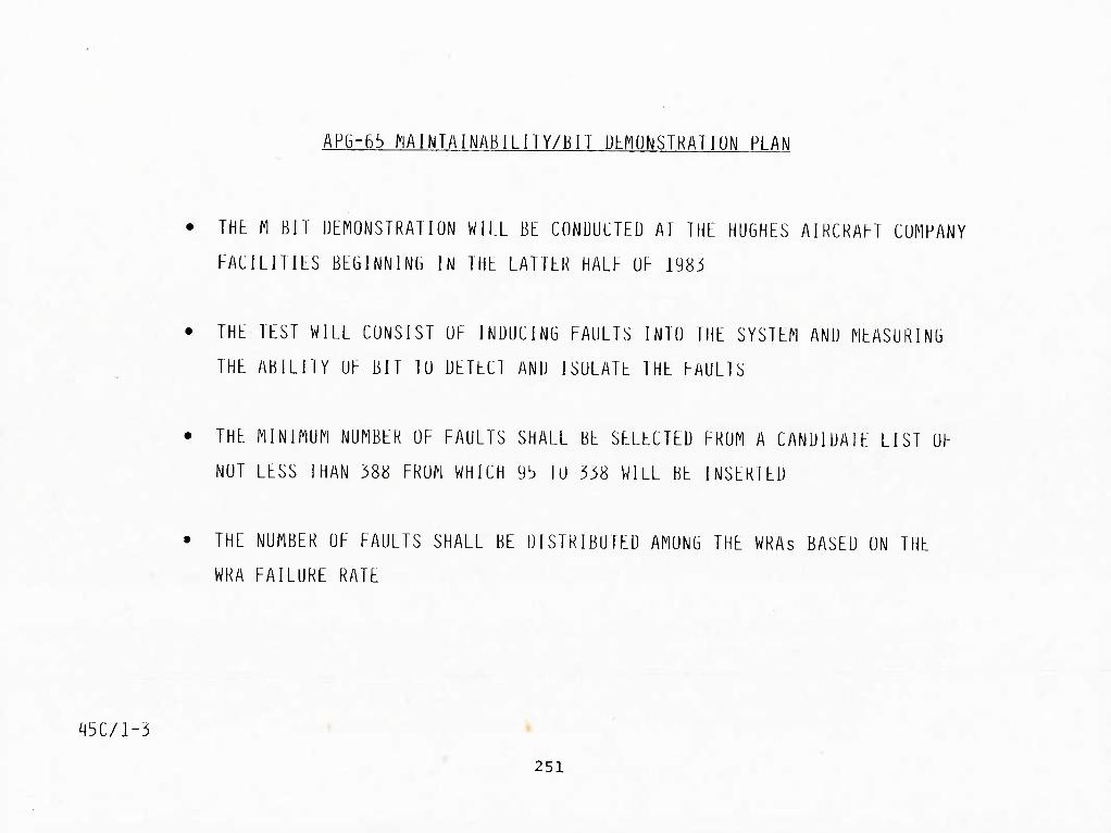
APG-65 MAINTAINABILITY/BIT ULFIUNSTKATIUN PLAN
• THt M BIT DEMONSTRATION WILL BE CONDUCTED AT THE HUGHES AIRCRAFT COMPANY
FACILITIES BEGINNING IN THE LATTER HALF OF 1983
• THE TEST WILL CONSIST OF INDUCING FAULTS INTO THE SYSTEM AND MEASURING
THE ABILITY OF BIT 10 DETECl AND ISOLAlE IHE FAULTS
• IHE MINIMUM NUMBER OF FAULIS SHALL BE SELECTED FROM A CANDIDATE LIST OF
NOT LESS THAN 388 FROM WHICH 93 10 338 WILL BE INSERIEU
• THE NUMBER OF FAULTS SHALL BE DISTRIBUTED AMONG THE WRAs BASED ON THE
WKA FAILURE RATE
^5C/l-3 » •
* . 251

IN-SERVICE BIT ASSESSMENT
The Navy's concern for BIT effectiveness in the fleet led to the formation of a joint
MCAIR/NAVAIR BIT assessment team. The assessment covered a one-year period from November
1981 through November 1982 at three different locations on the West Coast: LeMoore, China
Lake, and Pt. Mugu. The results led to changes in equipment software which were incorporated
in F37 and up aircraft. The Navy is continuing their assessment to determine the effectiveness
of the new software. MCAIR's involvement in this continuing assessment is now being
negotiated.
45B/7-24 252

IN-SERVICE BIT ASSESSMENT
NOVENBER 1981 TU QCT 1982
LEP100RE
5 AIRCRAFT
4 AIRCRAFT
6 AIRCRAFT
CHINA LAKE
4 AIRCRAFT
1981 1982 I JFMAMJJASUND J F ri A M J J A S 0 N D 1
RADAR BIT
FLIGHT HOURS EVENTS
924.0 46
612.1 24
237.3 15 1773.4
220.2 13
PT MUGU
2 AIRCRAFT 219.3 10
• BIT FIXES INCORPORATED INTO F-37
FINAL REPORT SUBMITTED TO NAVY FEBRUARY 1983
45A/13-16
FOLLOW-ON BIT ASSESSMENT IN NEGOTIATION
253

R&M ASSESSMENTS DURING FLIGHT DEMONSTRATION
The major R&M assessment points took place at the 1200 flight-hour point, at the end of
2500 FH and at the end of 9000 FH. All data from the beginning of flight testing up to
1200 FH was utilized for the first evaluation, with no credit being given for after-the-
fact corrective action. The second major milestone took place at the 2500 FH point with
aircraft F-9 flying a special 50-flight reliability demonstration program. The latest
milestone was a maintainability evaluation which took place at Lemoore Naval Air Station.
This evaluation covered four aircraft over a period of 6 months and ended at approximately
the 9000 FH point.
254 45B/8-33

R&M ASSESSMENTS DURING FLIGHT DEMONSTRATION
To evaluate the R&M performance, assessment points and locations were selected and
mutually agreed to by MCAIR and NAVAIR. The first three (i.e., 1200 FH, 2500 FH and 50
flight) demonstrations were conducted at NATC Pax River, Maryland. During these periods
maintenance was performed by MCAIR. The fourth evaluation, 9000 flight-hour, was conducted
at NAS LeMoore, California. Maintenance for this period was performed by VFA-125, the
first Navy fleet readiness squadron. The last evaluation, fleet supportability evaluation,
will be conducted during the first part of 1985. The location is not yet firm. However,
maintenance will be performed by the Navy or Marines.
45B/7-34
256

IN-SERVICE FAILURE ASSESSMENT IS CRITICAL TO R&M GROWTH '
In order to obtain an early assessment of the R&M problems, identify corrective actions,
and evaluate the effectiveness of design changes, it was deemed necessary to have R&M personnel
on site. Normal data retrieval from systems such as the Navy 3M does not allow for timely
and accurate problem identification. The F-18 program included joint MCAIR and NAVAIR on-site
monitoring at both Pax River and NAS LeMoore. This effort will continue into Eleet Sup-
portability Evaluation (FSE), where logistics as well as design problems will be evaluated.
45B/7-28
258

IN-SERVICE FAILURE ASSESSMENT IS CRITICAL TO R&^ GROWTH
• FSD AIRCRAFT: PAX RIVER
- SCORE: ICAIR/NAVY TEAM ON SITE TO EVALUATE EACH MAINTENANCE ACTION FOR
RELEVANCY. SUBSYSTEM MANAGER AND CONTRACTOR ASSISTED FORMAL
REVIEW BOARD IN ASSESSMENT OF CORRECTIVE ACTION.
- CORRECTIVE ACTION: CHIEF ELECTRONIC ENGINEER PRESIDED OVER FAILURE
REVIEW TEAM CONSISTING OF SUBSYSTEM MANAGER. EQUIPMENT ENGINEER.
AND RELIABILITY ENGINEER TO REVIEW EVERY RELEVANT AND PENDING
FAILURE. PURPOSE OF THE REVIEW WAS TO DETERMINE WHICH FAILURES
REQUIRED ADDITIONAL FOLLOW-UP.
• PRODUCTION AIRCRAFT: NAS LEMOORE
- EVALUATION: R&M TEAM ASSIGNED TO INITIAL TRAINING SITE TO IDENTIFY
PROBLEMS AND DETERMINE OPERATIONAL RELIABILITY. PROGRAM
VISIBILITY PROVIDED. NOT AVAILABLE THROUGH 3M.
45A/8-1 259


RtLIABlLITY/MAlNTAlNABILIlY STAhFING FUR KhMUTt SITtS
(NUMbFRS OF PEOPLE)
PATUXENT RIVER. MD 12U0 AND 2bU0 HR EVAEUATIUN
i M I D
lOV 78 THROUGH OCT 80 ^ ^ - '5
NAS LEMOORE. CA 9000 HR EVALUATION
NOV 81 THROUGH MAY 82 3 3
NAS LEMOORE. CA BUILT-IN-TEST EVALUATION
JAN 82 THROUGH SEP 82 2 2 i
• NAS LEMOORE. CA FOLLOW-ON R&M TRACKING
JAN 83 THROUGH SEP 83 2 2
• FLEET SUPPORTAHILIIY EVALUATION JAN 85 LOCATION - THU (ESTINAIED)
3 3
R - RELIABILITY
M - MAINTAINABILITY
I - INTEGRATION
U - DATA
45A/13-13 261

fRIOO - SEP 82 HROUGH FEB 83 'DATE - 18 APR I 3
AIRCRAFT - F/A-1BA
RELIABILITY AND MAINTAINABILITY SUMMARY FOR SELECTED EQUIPMENTS
WUC NOMENCLATURE
742G6 AS3254/APG65 ANTENNA
742G7 MT4955/APG65 ELECTRICAL EOUIPM
742GA AS3424/APG65 ANTENNA
742GG NOMENCLATURE UNAVAILABLE
742G9 NOC
ACTIVITY
VX -4 VX-4/VX-5 FIB 0 TOTAL
VFA-125 TOTAL
TOT 742GO AN/APG65 RADAR SET
742L6 NOMENCLATURE UNAVAILABLE
TOT 742LO NOMEN UNAVAILABLE
742Nt NOMENCLATURE UNAVAILABLE
TOT 742NO NOMEN UNAVAILABLE
74310 NOMENCLATURE UNAVAILABLE
TOT 743 10 NOMEN UNAVAILABLE
74364 NOMENCLATURE UNAVAILABLE
TOT 74360 NOMEN UNAVAILABLE
VMFA-314 VFA- 125 TOTAL
VFA-125 TOTAL
VFA-125 VX-4 VX-4/VX-5 Ft8 O TOTAL
VMFA-314 VFA-125 VX-4 VX-5 VX-4/VX-5 FIB O TOTAL
VFA-125 TOTAL
VFA-125 TOTAL
VMFA-314 TOTAL
VMFA-3 14 TOTAL
VX-4/VX-5 FIB 0 TOTAL
VX-4/VX-5 F18 0 TOTAL
VFA- 125 TOTAL
VFA-125 TOTAL
TOTAL TOTAL ML1 F LI GMT MAINT REPAIR TOTAL HOURS ACTIONS MFHBMA FAILURE FAILURE MFHBF
215 6 35.8 1 3 71.7 449 3 149. 7 0 3 149.7
4,275 36 118.8 1 1 1 388.6
2.900 22 131 .B B 8 362.5 4,275 22 194.3 8 B 534.4
390 1 390.0 1 1 390.0 2,900 6 4B3.3 3 3 966. 7 4.275 7 610.7 4 4 1,068.8
2,90O 1 2 900.0 0 0 4,275 1 4 275.0 0 0
2,900 3 966.7 0 3 966.7 215 1 215.0 0 1 215.0 449 1 449.0 0 1 449.0
4,275 5 855.0 0 5 855.0
390 2,900
215 321 449
4.275
2,900 4,275
2.900 4.275
390 4.275
390 4,275
449 4,275
449 4.275
2,90O 4,275
2,900 4.275
55 415 50 27 48
595
7. 1 7.0 4.3 11.9 9.4 7.2
2.900.0 4.275.0
2.900.0 4.275.0
390.0 4.275.0
390.0 4.275.0
449.0 4.275.0
449.0 4.275.0
2,900.O 4,275.0
2.900.0 4.275.0
2 26 7 2 2
39
8 1 1 1 20 1 1 28 178
0 O
0 0
0 o
o 0
48.8 26. 1 10.8 29.2 16.0 24.0
449.0 4.275.0
449.0 4.275.0
2.900.O 4.275.0
2,900.O 4.275.0
NAMSO 4790.A729B-01 PAGE 84
ACFT - F/A-1BA
UNSCH MAINT M/H EMT MAINT M/H PER PER MAN PER MAINT MAINT
HOURS F/H ACT ACT
24 . 109 3.9 3. 1
18 .039 5.8 5.2 214 .050 5.9 4.2
39 .013 1 .8 .9 39 .009 1.8 .9
6 .015 6.0 3.0 14 .005 2.3 1.3 20 .0O5 2.B 1.S
4 .OOI 4 . 2 2. 1 4 OOI 4.2 2. 1
1 1 .004 3.7 3.7 2 .009 2.0 2.0 8 OIB 8.0 6.0
2 1 .005 4 . 2 3.8
227 2.583
282 358 4 10
3.861
.582
.89 1 1.313 1.115
.914
.903
4 . 6. 5.
13. 8. 6.
2 5, 4 ,
10 7 5
6 .002 6.0 6.0 6 .001 6.0 6.0
6 .002 6 0 6.0 6 .O01 6.0 6.0
2 .005 2.0 1.0 2 .000 2.0 1.0
2 .005 2.0 1 .0 2 .000 2.0 1.0
1 .002 1 .0 .5 1 .OOO 1 .0 .5
1 .002 1.0 .5 1 .000 1 .0 .5
2 .001 2.0 2.0 2 .000 2.0 2.0
2 .001 2.0 2.0 2 .000 2.0 2.0
263

APG-65 RELIABILITY MANUFACTURING VERIFICATION TEST
Initial requirements for reliability manufacturing verification test included an all
equipment Production Duty Cycle (PDC) test. As production increased it was decided to
evaluate a sample test rather than testing all equipment. During pilot production
approximately 50% of the radar sets underwent PDC testing. No difference in reliability
was identified between tested and untested radar sets. This indicated that PDC.testing
was not necessary on every radar set. PDC testing is now performed on one out of ten radar
sets, or one radar set per month, whichever is less. The PDC test adds a significant cost
to each radar set and sample testing results in significant program savings.
The continuing sample PDC test will assure that the production program maintains the
reliability of the radar and test data will be tracked for indication of any negative
trends.
In January 1983, the first formal laboratory demonstration of APG-65 reliability was
successfully completed. The demonstration was performed to verify the intermediate MTBF
requirement of 85 hours specified for production radars 51-124. The test, performed on
radar sets numbers 85 and 94, was completed without failure, repair or other maintenance
on the radar. A total of 149 consecutive failure-free hours were accumulated during
continuous exposure to worst-case high and low temperature operating conditions. This is
equivalent to over four months of service use without maintenance and was sufficient to
satisfy the requirement to demonstrate a 106 hour MTBF. This early achievement of the MTBF
specified for radars serial number 125 and up qualified Hughes for the maximum incentive
fee award and could result in elimination of the next demonstration planned for set 125 and
an associated cost savings.
45B/7-17
264

APG-bb RAUAK RELIAblLlTY MANUFACTURING VLKII-ICATIUN TbST
• TEST CRITERIA
- SAMPEE: UNE RADAR PER TEN SYSIEMS OR UNE PER MUNTH
- ENVIRONMENT: TEST LEVEL F UF MIL-STD-781B
- ACCEPTANCE CRITERIA: REJECT LINE UF lESI PLAN II
- TEST TIME: FIFTY HOURS PER RADAR SYSTEM TESTED
• OBJECTIVE
- VERIFY MAINTENANCE OF RADAR RELIABILITY PERFORMANCE
THROUGHOUT PRODUCTION PROGRAM
- TRACK FOR NEGATIVE TRENDS
45C/1-3 265

SUMMARY AND r.HSSONS r.KARNKI)

SUMMAKY AND LtSSUNS LtAKNtU
267

45A/15-2
LESSONS LEARNED - DESIGN
APG-65 FAILURE NODES AND EFFECTS ANALYSIS (FNEA)
• ACROSS THE BOARD REQUIREMENT FOR FMEA TO PIECE PART LEVEL
IS NOT COST EFFECTIVE
• PIECE PART LEVEL ANALYSIS IS NECESSARY ON SAFETY ITEMS
(FLIGHT CONTROL. STORES MANAGEMENT. ELECTRICAL SYSTEM).
CRITICAL ITEMS. AND SELECTIVE SRAs
• PRIME CONTRACTOR NEEDS LATITUDE IN DETERMINING DEPTH
268

LESSONS LEARNED - DESIGN
APG-65 Rm DESIGN RELATED ANALYSES
EFEECTIVENESS
LOW MED HIGH
BLOCK DIAGRAM AND MATH MODEL X
ALLOCATIONS AND PREDICTIONS X
STRESS ANALYSIS X
OME ENVIRONMENTAL ANALYSIS x
FAILURE MODE AND EFFECTS ANALYSIS
- CRITICAL ITEMS X
- WRA LEVEL X
- SELECTIVE SRA LEVEL X
- 100% PIECE PART LEVEL X
SNEAK CIRCUIT ANALYSIS X
TEST ANALYZE AND FIX PROGRAM x
FAILURE ANALYSIS AND CORRECTIVE X ACTION PROGRAM
FAILURE REVIEW BOARD Y
45A/13-15 269

LESSONS LEARNED - TESTING
Start environmental test early and consider a combination of "Reliability Development"
and "Environmental Qualitication" tests. Use "OME" and accelerated stress in lieu of MIL-
Spec test environments.
Use all failure data for TAAF, including preproduction manufacturing test failures
(especially screening and burn-in). Consider projected growth based on patterns/fixes
identified, rather than number of test hours, to establish end point tor dedicated TAAF
testing (TAAF continues on all remaining test and later on field data). Efficient dedicated
environmental test and fix requires spares. Effective TAAF must include contractual
provisions for field R&M assessment and management review.
All-equipments production reliability test and formal reliability demonstrations are
very expensive. Benefits of both are potentially available through careful monitoring/
analysis of screening and burn-in failures and enforcement of "fix pattern failures" clause.
A measure of production reliability is necessary.
A "retrofit-on-repair" vehicle is badly needed for simple but important fixes in the
field. The incorporation of design changes into production units can experience lengthy
delays after PCA.
45B/8-9 270

45A/8-17
LbSSUNS LLAKNbU - TbSTING
• START ENVIRONMFNTAL TbST bARbY- CONSIUbR CUMBINATIUN UP "RbblABIblTY DbVbbUPMbNT" AND "bNVlRUNMbNIAb QUAblFlCAl lUN" TbSIS
- USb "0Mb" AND ACCEbbRATEl) STRbSS IN blbU UF Mlb-SPbCS
• USE Abb FAIbURb DATA FOR TAAF. INCbUDING PRbPROU MANUFACTURING IbSl FAIbliRbS (bSPbCIAbbV SCRbbNlNG AND BURN-IN)
- CONSIDER PROJbCTbD GROWTH BASED ON PATTERNS/FIXES IDENTIFIED. RATHER THAN NUMBER OF TESI HOURS. 10 ESTABEISH END POINl FOR DEDICATED TAAF TESTING (TAAF CONTINUES ON Abb RbMAINING TEST AND EATbR ON FlEbD DATA)
- bFFICIbNT UbDICATbU bNVIKONMENTAb TbSi AND FIX RbOUlRbS SPARbS
- bPFbCTIVE TAAF MUST INCEUDE CONTRACTUAb PROVISIONS FOR FIbbD R&M ASSbSSMbNT AND MANAGEMbNl RbVIbW
• Abb-EOUIPMENTS PRODUCTION RFLIABIblTY TbST AND FORMAb RbblABIblTY UbMONSTRATIONS ARb VbRY bXPbNSIVb
- BbNbFITS OF BOTH ARE POTbNTlAbbY AVAIbABbb THROUGH CARbFUb MONITORING/ANAbYSIS OF SCRbbNlNG AND BURN-IN FAlbURbS AND bNFORCEMENT OF "FIX PATTERN FAIbURbS" CbAUSb
• A "RbTROFIT-ON-RbPAIR" VbHICbb IS BADbY NbbDbD FOR IMPORTANT FIXbS IN THb FIbbD
o A MEASURE OF PRODUCTION REEIABIblTY IS NbCbSSARY
271

LKSSONS LKARNED - TKSTING
The objectives and results of all testing during FSD should be applied to TAAF. The
environmental qualification and dedicated TAAF testing should be combined and be comprised
of a combination of realistic operational profiles and accelerated stress exposure. This ;-
testing must be done very early in the program and the results should be combined with
those of the manufacturing screening and burn-in to identify failure patterns. In this way
the number of dedicated test articles can be reduced (however, ample spares are essential
for efficient environmental testing). Screening and burn-in of each article^provides
information not obtainable through protracted testing of a few samples. That is margin
problems and quality variations which are exposed by burn-in may not show up in testing
just a few samples. Burn-in also exposes "new" design margin problems which are inadvertently
introduced with configuration changes.
The APG-65 radar program experience supports this view:
• Great majority of failure patterns identified thus far were first seen in burn-in
• As a result, the planned test time was grea^tly reduced
• Several new problems associated with a configuration change package at serial number
55 were revealed by burn-in and corrected prior to aircraft delivery
• The results of environmental qualification and TAAF, which were partially combined,
showed that further integration would be possible
105/23-3 272

1U5/23-4
LESSUNS LtAKNtU - IbSIING
MAKE ALL TESTING TAAE & STKEAMLINE DEVELOPMENT TEST
- COMBINE ENVIKUNMENTAL OUAL & (DEDICATED) TAAE
USING UME AND ACCELERATED STRESS
- DU ENVIRONMENTAL TESl EARLY AND UTILIZE BURN-IN
RESULTS
273

LESSONS LEARNED - TEST
Reduced test time tor Reliability Development can be pursued if a Test Analyze and Fix
philosophy is being applied to all testing and also if a flight test program is running
concurrently with the RDT. A measuring stick to apply to the RDT test results is to watch
the corrective action being accomplished per unit of time. Thresholds tor measuring that
parameter can be determined and utilized for judgment in suspending the test.
A two-phase test, first starting with early development test units, then changing to
initial production units, allows the program to start early, run efficiently, and then test
the corrective action incorporated.
Emphasizing the aspect of uncovering failures instead of measuring MTBE leads to the
most open communication of problem areas.
An accelerated test, utilizing the corner of the environmental envelope, allows for
better test efficiency than spending a lot of test time at the normal operating points. A
danger with this approach is going overboard on the extremes and accelerations and causing
unnecessary problems.
274

LESSONS LEARNED - TEST
AP6-65 RELIABILITY DEVELOPMENT TEST
• CONSIDER REDUCED TEST TIME - 3.800 HRS SPECIFIED. 1.600 HRS ACTUAL
• CONSIDER TWO PHASE TEST -
- PRE-PRODUCTION UNITS
- INITIAL PRODUCTION UNITS
• DON'T STOP TEST TO INCORPORATE DESIGN CHANCES. TEST IN PARELLEL
WITH CHANGES
• EMPHASIZE TAAF NATURE OF TEST
• DE-EMPHASIZE MTBF MEASUREMENT
• CONSIDER ACCELERATED TEST VS. OME FOR RDT
• ACCOMPLISH HIGHER STRESS TEST FIRST
a5A/15-l 275

45A/8-liJ
APG-65 LESSONS LEARNED
• ENCOURAGE TOTAL TAAF (TEST ANALYZE AND FIX) CONCEPT
• PROVIDE TOOLS - FAILURE REPORTING
COORDINATION OF DATA FROM ALL lEST SOURCES
FAILURE ANALYSIS/CORRECTIVE ACTION
• MAINIAIN SOME FLEXIBILITY - DON'T OVERLOAD CAPACITY TO CONDUCT
FAILURE ANALYSIS - SOME SCREENING BY PROGRAM MANAGEMENT
• MAINTAIN BALANCED EMPHASIS ON CORRECTIVE ACTIONS FOR
RELIABILITY/PLRFORMANCE/MAINTAINABILITY PROBLEM AREAS
• ON UTILIZATION OF RELIABILITY DEVELOPMENT TEST
- CONVENTIONAL WISDOM: TEST. FAIL. STOP. DESIGN CHANGE. CONTINUE TEST
- PROBLEM: INEFFICIENT
- RECOMMENDATION: ALLOW TESTING IN PARALLEL WITH DESIGN ACTION
FIND MORE PROBLEMS SOONER
277

LESSONS LEARNED - MANUFACTURING
Manufacturing burn-in, with an extended failure-free period, can provide all of the
benefits of formal reliability demonstrations whether they be a sample test or an all-
equipment test, both of which were originally specified for the APG-65 radar. The formal
demonstrations attempt to measure the absolute value of MTBF. This requires elaborate
procedures and preparations such that failure "relevance" can be established. That is, so
that the true cause of each failure can be proven so as to separate failures chargeable to
test equipment or procedural faults, maintenance or troubleshooting errors, damage, etc.
This approach tends to be very expensive. The extended failure-free burn-in conversely
eliminates emphasis on "blame" for "relevant" failures while providing a strong supplier
motivation to eliminate or minimize all causes of burn-in failure to reduce costs.
The fact that burn-in does not yield an absolute value MTBF measurement need not be of
concern. Once the design has been verified, the on-going reliability is maintained by
quickly fixing any new pattern failures which may arise; this is an inherent result of the
failure-free burn-in procedure.
105/23-5
278

10'3/23-6
LtSSUNS LEAKNLIJ - HANUHACTUKIN6
hXPLOlT bURN-IN TU SUPPLANT PROIJUCTION RHLIABILllY IJtMUNSTKATIUN
- ALL-LUUIPMLNTS IJtMU INCURPAIIBLb WITH FACTORY
LQUlPMtNT
r FURMAL SAhPLL ULFIO LXPhNSlVL/UNNLCLSSAKY
279

F/A-18 RliLIABILITY LESSUNS-LEARNED
• ESTABLISH DESIGN-CENTERED. CnLLOCATED TEAM
• TAKE TRADE STUDIES SERIOUSLY AND CONSIDER RELIABILITY IMPACTS
« CONSIDER RELIABILITY EQUALLY WITH OTHER PERFORMANCE AND COST PARAMETERS
IN MAJOR PROCUREMENT DECISIONS
• CONCENTRATE ON DESIGN SIMPLICITY. PARTS DERATING. IMPROVED COOLING
• USE OME TO DESIGN AND TEST THE EQUIPMENT
• EMPHASIZE TEST ANALYZE AND FIX ASPECT OF RDT
• APPLY "TAAF" TO EARLY AIRCRAFT FLIGHT TESTING. USING OPERATIONAL
GROUND RULES
o DEMONSTRATE RELIABILITY AT THE AIRCRAFT LEVEL
• NEGOTIATE RELIABILITY DOLLAR INCENTIVES WITH CUSTOMER AND MAJOR
SUBCONTRACTORS
^5C/l-7 280

45A/8-16
AP(3-b5 MAINTAINABILITY LESSUNS i FARNFI)
• ESTABLISH EFFECTIVE DESIGN/LOGISTICS INTERFACE
• MAKE SUBSYSTEM MANAGERS RESPONSIBLE
• ESTABLISH REALISTIC DESIGN-TU REQUIREMENTS
• USE REVIEW AND COMMENT SHEETS FOR COMMUNICATION
TO DESIGN ACTIVITIES
• USE TRADE STUDIES TO BALANCE DESIGN AND
MAINTAINABILITY/LOGISTICS CONSIDERATIONS
• USE A CREDIBLE SIMULATION MODEL TO TRACK
OPERATIONAL READINESS PERFORMANCE
• PROVIDE A PROGRESSIVE BIT DEVELOPMENT/VERIFICATION
PROGRAM
281

10!)/23-7
MOKt LtSSONS LEARNED
• AMPLE SPARES AND PARALLEL TEST/FIX ESSENTIAL
FUR EFFICIENT TAAF
• INTEGRATE BIT DEVELOPMENT WITH TAAF
• PROVIDE ON-SITE CONTRACTOR SUPPORT THROUGH
INTRODUCTION TO COMPLETE TAAF R AND M
• PIECE PART LEVEL FMEA AND SNEAK CIRCUIT
ANALYSIS HAVE LIMITED EFFECTIVENESS FOR RADAR
• CAREFUL ANALYSIS FOR NOISE/TRANSIENT SUSCEPTIBILITY
OF TRIP-CIRCUITS HAS HIGH PAYOFF
• VECP PROGRAMS PROVIDE R&M BENEFITS
282

APG-b5 BIT RECOMFIENUATIUNS
INITIAL - ESTABLISH FULL UP BIT HARDWARE/SOFTWARE DESIGN (EMPHASIZE EARLY
HARUWARE/SOFTWAKE UEVELUPMENT) REQUIREMENTS .
DEVELOPMENT - ANALYSIS (STRATEGIES TO MINIMIZE FALSE ALARMS AND CNDs) '
- INITIAL BIT ASSESSMENT (FAULT INSERTIONS)
- TAAF CONCEPT - USE ALL TEST SOURCES (FAILURE MODES EXPERIENCED
IN OPERATIONAL ENVIRONMENT)
- EMPLOY A SINGLE THREAD. CLOSED LOOP DATA SYSTEM 10 ENSURE AND
TRACK SYSTEM MATURATION
- DEVELOP A MIXTURE OF AUTOMATIC AND MANUAL DIAGNOSTICS TO ENSURE
ACHIEVEMENT OF 100% DIAGNOSTICS CAPABILITY
PRODUCTION - USE AND TRACK BIT CAPABILITY TO ESTABLISH CONFIDENCE IN BIT.
MATURE BIT SOFTWARE
GROWTH - CONTRACT PROVISIONS FOR BIl GROWTH, ON-SITE EVALUAllON
45/8-15 283

■frf-5p.? .
U212692
•J»K