assembly machine - defense technical information … · all other editions are obsolete....
TRANSCRIPT

UnclassifiedSECURITY CLASSIFICATIONI OF THIS> PAGE
ORT DOCUMENTATION PAGEla. lb. RESTRICTIVE MARKINGS
2a. - 70 3 DISTRIBUTION / AVAILABILITY OF REPOR
7b. No restriction ELECTE4. PERFORMING ORGANIZATION REPORT NUMBER(S) 5. MONITORING ORGANIZATION REPL., (..
DE89-0342262014B . n
6a. NAME OF PERFORMING ORGANIZATION 6b OFFICE SYMBOL 7a. NAME OF MONITORING
I (If applicable)Delco Systems Operations General Dynamics/ Fort Worth
6c. ADDRESS (City, State, and ZIPCode) 7b. ADDRESS (City, State, and ZIP Code)
Goleta, CA 93117 Fort Worth, TX 76101
8a. NAME OF FUNDING/SPONSORING Bb. OFFICE SYMBOL 9. PROCUREMENT INSTRUMENT IDENTIFICATION NUMBERORGANIZATION (If applicable) Contract#F33657-82-C-2034
F-16 SPO I ASD P.O. #1005206
8c. ADDRESS (City, State, and ZIPCode) 10. SOURCE OF FUNDING NUMBERS
PROGRAM PROJECT ITASK IWORK UNITELEMENT NO. NO. NO. ACCESSION NO.
Dayton, OH 4543311 TITLE Inclde Security Classification)Phase 2 Final Project Report - #1 Pick and Place Assembly Machine (Automated CCA ComponentMounting.)
12. PERSONAL AUTHOR(S)
rfn E OF REPORT 13b. TIME COVERED 14. DATE OF REPORT (Year, Month, Day) 15. PAGE COUNT
UIFROM 1984 TO 1987 87,02,28 26
16. SUPPLEMENTARY NOTATION
CDRL ITM-004
17 COSATI CODES 18. SUBJECT TERMS (Continue on reverse if necessary and identify by block number)
FIELD I GROUP I SUB-GROUP, l >Automatic P4,. - Place Machinery, Automatic Component13 I 9 1 Mounting-/4 c -Jr s rj% ,
19tiBSTRACT (Continue on reverse if necessary and identify by block number)
Both leaded and leadless surface-mount components will be automatically placed on PrintedWiring Boards (PWBs). A pattern recognition vision system will identify circuit board
positions and feed offset information to the host microprocessor. A pick and placemachine will be programmed to interface with the microprocessor and individually mountprepared parts to the board surface.
Dfr O ~ STATEMEM TAAppovd fox public elesel
.Dixriuton Unl1Ited-
20. DISTRIBUTION /AVAILABILITY OF ABSTRACT 21. ABSTRACT SECURITY CLASSIFICATION
OUNCLASSIFIED/UNLIMITED 0] SAME AS RPT. 0 DTIC USERS Unclassified22a. NAME OF RESPONSIBLE INDIVIDUAL 22b. TELEPHONE (Include Area Code) 22c. OFFICE SYMBOL
Captain Curtis Britt 513-258-4263 YPTMDO FORM 1473.84 MAR 83 APR edition may be used until exhausted. SECURITY CLASSIFICATION OF THIS PAGE
All other editions are obsolete. Unclassified
89 "" 138

28 February 1987
~1
i1 INDUSTRIAL TECHNOLOGYMODERNIZATION
Phase II Final ReportI Project 1
Pick & Place Assembly Machine
INDUSTRIA L'-TECHNOLOGY MODERNIZATIONPROGRAM -
Prepared for Accesion ForGENERAL DYNAMICS NTIS CRA&I
Fort Worth, Texas DTiC TAW 0
Unannoo .icedContract No. F33657-82-C-2034 Juslificat.
By..-Distribution I
Avaidability Codes
Delco Dist iSpCldlSystemsC3Operations I
DELCO ELECTRONICS CORPORATIONGoleta. California 93117

FINAL REPORT
CATAGORY I PROJECT I
I PICK AND PLACE ASSEMBLY MACHINE

* REPORT BASIS:
This final report is prepared following the guide linesfor a catagory I type project. This project was entirelyresearched, designed, developed and fabricated with DelcoElectronic's Div. of General Motors funding.
Being a catagory I type project without support fundingfrom the ITM Program, the following final report is con-densed as opposed to a typical catagory II type project.
OBJECTIVE:
Objective was to provide an assembly method for .low volumeAvionic's products utilizing a mix of leaded flatpacks,
leaded quadpacks and leadless chip carrier devices. Themachine was intended to be flexible, automated to require aminimum of operator intervention and provide the placementaccuracies required by military electronic circuit board
assemblies.
TECHNICAL APPROACH FOLLOWED:
To meet the objectives of:1
1. Achieving component placement accuracies within + .0035".
2. Parts handling flexibility.
3. Hands on labor reduction thru automation.
4. Assemble circuit boards in batch lots as small as ten
units.
The following approach was employed:
1. Placement accuracy of + .0035" is required to insure thepart leads are within the solder pad geometry on thecircuit boards. The variables to be considered includethe part forming dimensions, basic tolerances of partsprocured to Mil-Std 38510, "SWIM" and manufacturingvariability within the circuit board, basic circuitboard registration and the placement accuracy of the
machine.
Automatic compensation for the possible variablesdictated:
a. Vision system to inspect each part and identify trueposition of each lead in the foot area which mustultimately fall within the solder pad geometry.
b. Provide a method of maintaining accountability for
parts which are rejected by the vision system for
part lot traceability.
1 .-
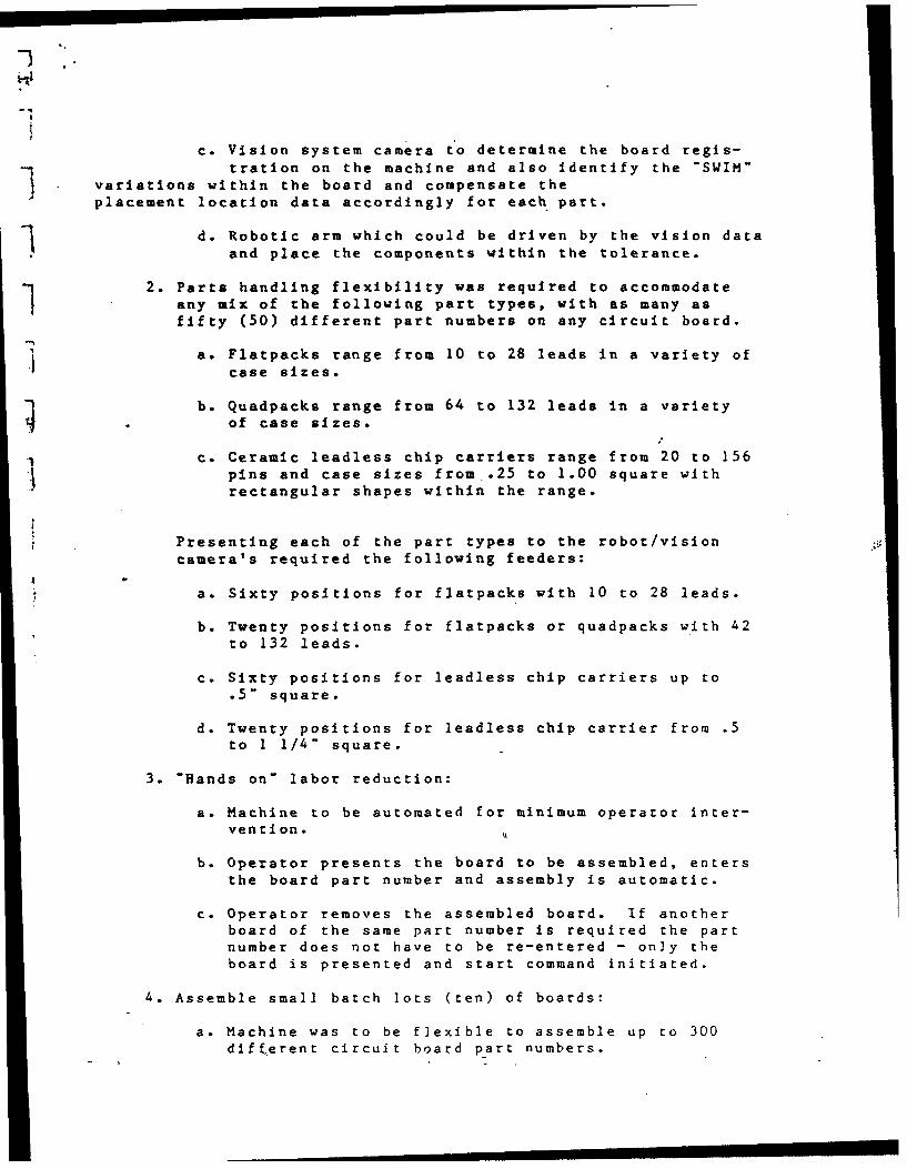
c. Vision system camera to determine the board regis-
tratlon on the machine and also identify the -SWIM"variations within the board and compensate the
placement location data accordingly for each part.
d. Robotic arm which could be driven by the vision dataand place the components within the tolerance.
2. Parts handling flexibility was required to accommodateany mix of the following part types, with as many asfifty (50) different part numbers on any circuit board.
a. Flatpacks range from 10 to 28 leads in a variety of
case sizes.
b. Quadpacks range from 64 to 132 leads in a varietyof case sizes.
c. Ceramic leadless chip carriers range from 20 to 156
pins and case sizes from .25 to 1.00 square withrectangular shapes within the range.
Presenting each of the part types to the robot/vision
camera's required the following feeders:
a. Sixty positions for flatpacks with 10 to 28 leads.
b. Twenty positions for flatpacks or quadpacks with 42to 132 leads.
c. Sixty positions for leadless chip carriers up to.5" square.
d. Twenty positions for leadless chip carrier from .5
to 1 1/4" square.
3. -Hands on" labor reduction:
a. Machine to be automated for minimum operator inter-vention. %
b. Operator presents the board to be assembled, entersthe board part number and assembly is automatic.
c. Operator removes the assembled board. If anotherboard of the same part number is required the partnumber does not have to be re-entered - only theboard is presented and start command initiated.
4. Assemble small batch lots (ten) of boards:
a. Machine was to be flexible to assemble up to 300
different circuit board part numbers.

b. Board program data to be down loaded from a hostand programs for each board to reside in a harddisk on the cell.
c. Operator changeover from one board part number toanother to be limited to loading the parts.
d. All operation including maintenance trouble shootingto be menu driven.
EXPLANATION OF TECHNICAL APPROACH TASKS:
1. Existing methods (prior to this machine design) weremanual assembly of each part on the circuit board.
2. Industry/vendor survey determined, that no availableequipment would meet the objectives of this machine atthe time.
• Machines to place leadless chip carriers were avail-able but could not provide the assembly mix of flat-packs, quadpacks and leadless chip carriers required.
. No capability could be found for flatpack assembly.
. No capability could be found for a 132 pin quadpackon .025 centers. In addition, in-house prototypeassembly of this type of part was found to be far tolabor intensive to be done manually.
. Isolated capability for one part type could be foundbut no commercial vendor was receptive to developeall the capability into one machine.
• During the vendor survey we were able to find asource capable of developing and integrating thevarious technologies. We ultimately used this sourcefor development, design & fabrication of the machine.
3. Proposed technical approach:Detailed "statement of work" was written and presentedto (see attached):
Automation Tooling Systems, Inc.80 Alpine Rd.Kitchener, Ontario,Canada N2E lAI
The highlights of the approach included:
a. Cycle times of 5 seconds per part.
b. Placement accuracy of + .0035".
m1nmnimiiillil am|I

*c. Pattern recognition of the parts and boards des-
cribed above.
d. Totally automatic operator menu driven system.
e. Program generation off line from a CAD with down
load to the cell.
f. Self diagnostics, menu driven calibration, andtrouble-shooting.
g. Parts presented in Delco designed carriers and
magazines.
h. Part inspection for bent leads and polarity.
i. Fifteen minute changeover for different partnumber assemblies.
4. Preliminary cost benefit analysis:
a. Quotation for development, design, and fabricationwas provided by ATS.
b. "Hands on Labor Savings-*of hand assembly versesassembly using the above approach was estimatedto average .53 hours per circuit board assembly(dependant on the number of parts).
c. R.O.I. was generated on a five year volume forecastand the estimated savings per board using thequoted cost by ATS. R.O.I. was found to be withinthe General Motors guideline for the investment.
5. Equipment alternatives:
Due to negative results of the vendor surveys, only
minor change to the proposed approach were considered.The basic design approach remained as proposed.
6. Preliminary designs/development, machine layout concept
and configuration was provided by ATS. The pattern re-cognition capability was demonstrated to our in-housevision experts in a lab enviroment and was considered tobe sound.
7. Final design:
a. Final mechanical design review was held at ATS.prior to starting fabrication.
b. Numerous contacts between ATS personnel and Delcosoftware people were held to work out both machineinternal software and CAD data programs.

8..Implementation:
a. Machine was fabricated and demonstrated at theATS facility In Aug/Sept. of 1985.
b. Machine was delivered h installed in a lab at Delcoin Oct/Dec. of 1985.
c. Limited production hardware was assembled on themachine from Jan. 86 to the present. During thisperiod numerous minor changes in design and im-provements were implemented. Machine is presentlywaiting completion of the final manufacturingarea. Actual move and full implementation in manu-facturing will be completed by June of 1987.
d. Resolution of problems:
Delco provided a direct dial-up phone line into thecell computer and into the plant host. This permit-ted ATS/Delco to work and revise software as eachproblem occured. Both the vendor and Delco couldthereby monitor problems in real time.
e. Technology, transfer:
The technology used in this cell is available fromAutomation Tooling Systems. Further detail in thisreport is not worthwhile as following this develop-ment, ATS has further refined software approaches,improved vision hardware is available and numerousother robotic developments have been defined. Vis-ion guided robotics is a very dynamic technologyand direct vendor contact is more advantageous.
LI

, . .
w1
E REV
D un SUBCONTRACT PROCUREMENT STATEMENT OF WORKDel 1co ElectronicsNO. 421-MD 1939 sup
..1
FOR AUTOMATION TOOLING SYSTEMS, INC.
RELEASE TO DESIGN & FABRICATE
A PICK N' PLACE ASSEMBLY MACHINE
FOR DELCO ELECTRONICS-MILWAUKEE AVIONICS PRODUCTS
PICK N' PLACE ASSEMBLY STATION
P/N FD-778841
APRIL 24, 1984
WRJTTEN BY: / / ZI 1 H. CULVER
-j MANUFACTURING ENGINEERINGMILWAUKEE, WI
APPROVED BY:aH. KENNEDY, ASST. SUPERINTENDENT
MANUFACTURING ENGINEERING
REVISION I 05/10/84PARA. 8.1 REVISEDPARA. 8.1.5.4 REVISEDFIG. 7 ADDED
REVISION II 06/28/84REVISED TO REFLECT QUOTATION #1246
.-9 & VERBAL AGREEMENTS BETWEEN A.T.S& H. CULVER.
PAGE 1 OF 16
AGE
FORM 1039 REV 1066
-.. -. -,,
,

Delco Electronics SUBCONTRACT PROCUREMENT STATEMENT OF WORK
NO. 421-MD 1939
" ,
1.0 SCOPE
This Statement of Work and associated attachments establishesthe requirements for procurement of a Pick and Place AssemblyStation.
2.0 APPLICABLE DOCUMENTS
2.1 General Motors Corporation
2.1.1 GM Basic Electrical Standards for Industrial-i Equipment, dated April 1980.
4 2.1.2 GM Sound Level Specification for Machinery &Equipment dated 1 June, 1971.
2.1.3 Fluid Power Standards for Industrial Equipment
Section R, dated Sept. 1970.
2.2 Delco Electronics
Delco Electronics Specifications for IndustrialEquipment,. dated May, 1983.
Exceptions to this document for this work statement areas follows:
Para. 17.1.1 - Shipping instructions to be obtained fromMr. M. Friebert by calling 414-768-2953.
Para. 18.1.1 - The approving authority at DelcoElectronics, Milwaukee is the Work Statement originator.All approval prints, final drawings, or reproducibles,requests for deviation and questions concerning thisspecification shall be addressed to:
Delco Electronics Division7929 South Howell AvenueOak Creek, WI 53154Attn: Mr. H. D. Culver
Mail Station 1A02OTelephone: 414-768-2346 PAGE
FORMA 1039 REV 1066

Delco Electronics SUBCONTRACT PROCUREMENT STATEMENT OF WORK RDc NO. 421-MD 1939 suP
I}$
Para. 20.2.1 - Delete reference to requirements ofIndiana Law (IC 1971, 22-8-1.1 et, seq.)
On Page 38 under "PROGRAMMABLE CONTROLLERS' deleteModicon.
12.3 Occupational Safety and Health Act dated 18 October,1972, Part 1910, 219. Mechanical Power Transmissionapparatus to be obtained by the contractor.
3.0 ARTICLES & SERVICES TO BE SUPPLIED BY THE CONTRACTOR
3.1 Equipment
a. Design
b. Fabrication
c. Delivery
3.2 Engineering Data
a. Layout Drawings
b. Final Drawings
c. Specifications
d. Manuals
e. Spare Parts List
3.3 Progress Information
3.4 Training
3.5 Quality Assurance Provisions
3.6 Warranty
PAGE]
FORM 1039 REV 1066

II
Delco Electronics SUBCONTRACT PROCUREMENT STATEMENT OF WORK
NO. 421 -MD 1939 suP
4.0 DESCRIPTION OF ARTICLES & SERVICES
4.1 Equipment
4.1.1 Design. The Subcontractor shall execute all newdesigns and the necessary modification toexisting designs to meet the requirements of theAttachments to this Statement of Work. Shouldthe Subcontractor have an engineering standardpractice on design which conflicts with thisStatement of Work, he may submit this standard,provided he states in detail the variance fromthis Statement of Work to the Author. If no exceptionsare stated, Delco Electronics will require the Subcontractorto fulfill all details of this Statement of Work.
4.1.2 Fabrication. The Subcontractor shall fabricatethe Pick and Place Assy. Station per the require-ments of this Statement of Work.
4.1.3 Delivery. The Subcontractor shall be responsiblefor the packaging and safe delivery of the Pickand Place Assy. Station to Delco Electronics.
4.1.4 The Subcontractor shall act in an advisorycapacity during the installation of the equipmentat Delco Electronics.
4.2 Engineering Data
4.2.1 A drawing outlining the Pick and Place Assy.Station showing approximate dimensions, weight,mounting points and requirements for access-ibility, operation and maintenance.
4.2.2 One reproducible electrical and pneumaticschematic and block diagram showing selectedcomponents.
1
FORM 1039 REV 1066

-.1
E SUBCONTRACT PROCUREMENT STATEMENT OF WORK REV
NO. 421 -MD 1939tsupP
4.2.3 Final Drawings. One set of reproducible and oneset of non-reproducible drawings of the Pick &Place Assy. Station shall include the followinginformation as a minimum:
a. Parts List - Including generic part numberwhere applicable.
b. Electrical, pneumatic and hydraulic
schematics.
c. Cable and wire list.
d. Modifications made to purchased commercialequipment.
e. Assembly "drawings and all mechanical detaildrawings.
4.2.4 Operation and Maintenance Manuals. The Sub-Contractor shall generate and submit two copiestoL Delco Electronics of an OPERATION &MAINTENANCE manual which shall be suitable foruse by skilled technical level personnel in therepair, maintenance and the operation of thePick and Place Assy. Station.
The MAINTENANCE manual shall contain sufficientinformation to permit servicing down to thecomponent level.
4.2.5 Spare Parts List. The Subcontractor shallsubmit one list of recommended spare parts.Quantities listed shall be sufficient to supportone piece of equipment for one year.
4.3 Training - Two day Familiarization Courses for four peoplewill be provided.
4.4 Quality Assurance Provisions
4.4.1 Notification of Readiness for Acceptance. TheSubcontractor shall notify Delco Electronics ofreadiness of the Pick and Place Assembly Stationfor acceptance. This notification shall be givenat least (3) three days before the scheduledacceptance start date. Notice of cancellation orchange of an acceptance date shall be given atleast one (1) day in advance of any scheduled PA GEacceptance date.
FORM 1039 REV 1066

tIREY
Delco Electronics SUBCONTRACT PROCUREMENT STATEMENT OF WORKW NO. 421-MD 1939 :suPP
4.4.2 Preliminary Acceptance. Preliminary acceptanceof the Pick & Place Assy. Station shall beaccomplished at the Subcontractors facility.A functional demonstration in compliance with therequirements of this Statement of Work shall beconducted in the presence of authorized DelcoElectronics Representatives.
4.4.3 Final Acceptance. Final acceptance of the Pick& Place Assy. Station shall be accomplished atDelco Electrokics and shall be based on demon-stration of compliance with the requirements ofthis Statement of Work. A final acceptance shallbe conducted in the presence of authorized DelcoElectronics Representatives.
4.4.4 Equipment Verification. The Subcontractor shallmaintain technical liaison with Delco Electronicsto correct deficiencies and/or to effect improve-ments in the operation and design of theequipment during the warranty period.
5.0 Mailing Instruction. The mailing address for documentation, reportsand notices shall be as follows:
Delco Electronics DivisionGeneral Motors CorporationP. O. Box 471Milwaukee, WI 53201Attn: J. Lukomski, PurchasingDept. 0417, M/S lA09
cc: H. CulverDept. 421, M/S lA02"
PAGEI
FORM 1039 REV 1066

- I ~- SBCONRACTPROUREMENT STATEMENT OF WORKDelco lectronics SO 42 -C RE3
E3Pf OMIt .C.$ W NO. 421-MD 1939 YUPP
'7 6.0 DETAIL REQUIREMENTS FOR A PICK N' PLACE ASSEMBLY STATION:
6.1 INTROCUCTION: A.T.S. will provide a Turnkey System7utilizing a Seiko RT2000(3000) Robot, A.T.S. designed partsfeeders and Vision System incorporating three caigeras(Solid State perferred). Two cameras being employed forcomponent alignment and one camera mounted on the Robot armto scan the PWB for alignment and Swim. The board will bescanned for actual part location and positioning with theoffset deviation presented to the Robot. The Robot willpick up a component, present it to the Vision System,correct part positioning in X, Y & 0 while moving to theplacement locltion.
71 6.1.2 Develoment of a Pick N' Place Assembly Machine with thefollowing guidelines:
6.1.2.1 Machine is intended to be extremely flexible and capable
of populating various size substrates with a variety ofsurface mounted components.
6.1.2.2 Machine is intended for low volume usage with easychangeover to permit small batch processing of varioussubstrate configurations.
6.1.2.3 Substrates will be populated on both sides, one side ata time, in small batch loads of 10 substrates or lessper setup.
6.1.2.4 All parts to be handled are Electro-Static Sensitive andequipment described is to be properly protected.
PAGE
7PORM 1039 REV 10"4

Iii3 11c EectoncsSUBCONTRACT PROCUREMENT STATEMENT OF WORK E
DloEetoisNO. 421-MD 1939 s u-PP
7.0 GENERAL MACHINE DEFINITION:
7.1 Substrate Flexibility. Machine must be designed to handlethree substrate sizes (2.7 x 3.4, 4.5 x 6.5, 6.5 x 9.5)with easy tooling changeover for various configurations ofthese sizes. Substrates will be populated on both sides,one side at a time. Delco Electronics will provideSubstrate Holding Fixtures.
7.2 Parts Handling Flexibility.
a.- Machine must be capable of selecting parts in"Flatpack/Quadpack" form from 60 locations with partshoused in 1 1/4" square carrier/magazines and 20locations with parts housed in 2" squarecarrier/magazine sticks. Leaded parts will bepresented to the machine with parts pretinned,preformed and precut. Each part will be contained ina "Delco Designed" one piece type carrier in
-1 consistent polarity orientation. Carriers containingthese parts will be presented in stick magazines.(See Fig. 4 for typical carriers and magazines forreference only.) Delco Electronics will providecarriers and magazines.
b. Machine must be capable of selecting parts in leadlessI chip carrier form from 60 locations with parts up to
1/2" size and 20 locations with parts in 1/2" to1 1/4" ranqe, all in sticks without carriers. Leadlesschip carriers will be presented in sticks with theLCC's pretinned and in consistent polarityorientation. (See Fig. 4 for typical magazine -Reference Only.) Delco Electronics will provideplastic sticks.
.A,..
PAGE
8FORM 1039 REV 1066
..................

I: Delco Electronics SUBCONTRACT PROCUREMENT STATEMENT OF WORK
6I NO. 421-MD 1939 ISuPP
I!
c. Machine must be capable of selecting chipcapacitors and resistors from two different partsvibratory feeders, which are interchangeable.*1 These feeders are not part of the design, butspace must be provided for later installation.
d. In summary, a fully parts stocked machine willselect parts from 162 different parts feeders(80 P/N stick magazines with "Flatpacks/Quadpacks"in carriers, 80 P/N stick magazines with leadlesschip carriers and two different vibratory chipfeeders.)
e. All machine interface with parts magazines, partscarriers, and parts shall be conductive or provide"ESD" protection to the parts thru all processing.
j f. Each magazine feeders(Leaded and Leadless) will be providedwith the standard A.T.S. designed Low Level Indicator,providing a bank of parts below the magazine/stick whichJ permits changing magazine/sticks while the machine is inoperation.
7.3 Parts Description:
a. For alignment and handling considerations, leaded devices inFlatpack or Quadpack configurations to be placed by themachine, in this Statement of Work range as follows:
.1 I
PAGE
FORM 1039 REV 1066

1 Delco Electronics SUBCONTRACT PROCUREMENT STATEMENT OF WORKNO. 421-MD 1939
FIGURE 1FLATPACK CONFIGURATIONS
-B" "A"CASE SIZE TOE-TO-TOE DIMENSIONS
(Mil 35810 "E* Length)
.240/.260--> - .400 or
.240/.300--> - .450 or 10,14,16, 20 & 24 Pin1Devices
.240/.300--> -.500 or
.245/.420--> - .600 or1 20,24 & 28 Pin Leaded Device
.245/.420--> - --. 666 or
_i .245/.505--> - -- 700 or.620/.660--> - -- l.100--42 Pin Leaded Device.620/.660--> 1.166--42 Pin Leaded Device
1A7
NOTE: Flatpack device configurations will range from 10Leads to 42 Leads with Lead Spacing at .035 "or .050".
.PAG
FORM 1039 REV 1066

Delco Electronics SUBCONTRACT PROCUREMENT STATEMENT OF WORK R
NO. 421-MD 1939 SUPP
FIGURE 2QUADPACK CONFIGURATIONS
S'A7 "B" "A" DIM.CASE SIZE TOE-TO-TOE DIMENSIONS
f--l.120 - 132 Pin Leaded
1.200 - 60 & 64 Pin Leaded.166 Device
NOTE: Quadpack device configurations will range from 60to 132 leads with lead centers on .025" and.050" spacing.
b. Leadless'chip carrier devices to be placed by themachine in this Statement of Work will be square orrectangular shaped within the ranges shown below.Tolerances between "Case to Metalized Foot Print TruePosition" on larger Hi-Density devices will necessitatepattern recognition for alignment. Approximately 95%of LCC's to be placed will have tolerances suitable topermit mechanical nesting or crowding for alignment.
S I
PAGE
FORM 1039 REV 1066

REDecoEecrnisSUBCONTRACT PROCUREMENT STATEMENT OF WORK RVE lcaElcwnc NO. 421-MD 1939 1SUPP
FIGURE 3LEADLESS PARTS
-25I-
Dimensions are for reference only, -as actual part configurationsI I will range from 16 pins to 156 pins in leadless carrier form.
FORMA 1039 REV 1066

E3 Delo ElecronicsSUBCONTRACT PROCUREMENT STATEMENT OF WORK i
03c lmtrcNO. sp i
1X 6 0 VAO/e7w4
PAXGiXI3D 701 ZTTE6ZeoE P C==" eE/=
PAG
-13
FORM4 Z~ 109RV16

-IREY
DOelco Electronics SUBCONTRACT PROCUREMENT STATEMENT OF WORKD NO. 421-MD TOPe
7.4 Physical Break Down: Machine Disassembly shall permitbreak down into component sub-assemblies with maximumsizes of 3 1/2 feet x 8 feet to permit inter-plantrelocation.
7.5 Machine Setup Time: Total machine setup time, to changemagazine sticks on 60 of the 162 part tyes, and performinitial substrate alignment shall not exceed 30 minutes.
7.6 Finish: Exterior of the Pick N' Place Assembly Stationshall have a "Blue" or "Green" exterior machine enamel.
7.7 Installation Instructions: Installation instructions toaugment the final drawings for power drops, air lines,venting requirements or special instructions detailed to askilled trades level are required sixty (60) days inadvance of equipment delivery.
7.8 Space will be provided- within the Robot working envelopeto permit the addition of four "Flatpack or LCC" and one"Quadpack" standard A.T.S. Centering Stations for future"Add-On", if necessary, or this space will permitadditional vibratory chip feeders to be added later.Machine control will provide I/O ports to operate these
devices.
7.9 Accuracy: Total placement accuracy of the metalizedfootprint on Leadless Chip Carriers or LeadedFlatpack/Quadpacks to the pad Footprint pattern on theboard/substrate shall be within + .0035 inches, includingboard/substrate "Swim" variations.
7.10 Machine Cycle Time: Total machine cycle time to obtain,center, align, place and recycle to pickup the nextcomponent shall not exceed 5 seconds on a 6" x 9"board/substrate placement area.
7.11 Programmable "Z" Axis: Vertical Z Axis movement shall beH.500 inches minimum with programmable set-down pressures
of 75 to 150 grams.
7.12 End Effectors: Grippers or vacuum cups shall becompatible with the parts variations described. Grippersor vacuum cups. shall permit component body to bodyplacement with .005 minimum clearance between parts inFlatpack configurations. Gripper or vacuum cup manualchanges are permitted, but changeover shall not exceed 1minute of operator time.
4FORM 1039 REV 1066
4;- i I I

REVDelco Electronics SUBCONTRACT PROCUREMENT STATEMENT OF WORKDa co Ec ni NO. 421-MD 1939 ZsuPP
7.13 Positioning: Parts Positioning and Board/Substratepositioning will be accomplished using pattern recognitiondefined by the contractor. (Note: Flatpack devicespresented at the pick-up point in Delco Electronicscarriers will be on center across the part body, but may2 be off-center along the Leaded Axis byt .075 worst case.)
7.14 Carriers: Carriers provided by Delco Electronics forFlatpack and Quadpacks will nest the parts withoutretainers, therefore, openers are not required. Carriersare color coded and can be ejected into a common bin foroff-machine sorting after part removal.
8.0 OPERATING SYSTEM:
8.1 Machine Operating System will be "Menu" driven andcompatible thru a RS232 link with a Digital EquipmentCorp., VAX host or a Data General Host Computer.
8.2 System will permit program entry via three methods:
a. Walk thru digitizing teach process wherein the machinecan be jogged thru all functions and each pointstored. Each feeder can be manually operated thru athumb wheel or toggle switch panel with "B.C.D." typeinput. Program will reside on disk at the machine.
b. Program entry can be keyed in on a terminal to addressall feeders and board/substrate co-ordinates andstored. Program will reside on disk at the machine.
c. Programs can be down-loaded from a host. System willpermit editing a program and overlaying revisions onthe program in residence in the host.
8.3 Self-diagnostics, no part,,detection, alternate magazineselection and program editing features are required.
9.0 OPERATOR/MACHINE INTERFACE:
9.1 Ground Rules: Boards/Substrates are presented forpopulation to the machine in "Kits" of ten or less. Partsare preformed and preloaded in magazine sticks in carriers(when applicable) by part number and lot number for therun of board/substrates contained in the kit.
PAGE
15FORM 1039 REV 1066
-- • ..i I I I

ESUBCONTRACT PROCUREMENT STATEMENT OF WORKDe.co E =ectronics NO.421-MD 1939 SUPP
9.2 Machine Operation:
9.2.1 Operator will load a disc by P/N and side "A" or "B" to beassembled, or, operator will enter P/N and side into theterminal if direct tie to the host is utilized.
9.2.2 Computer will ask the host (if applicable) for the programand the on-board microprocessor will prompt the operatoracknowledging the program transfer.
9.2.3 Program will ask the operator to install a magazine ineach feeder by part number and acknowledge presence.Repeat for each magazine required for the assembly.Operator will be permitted to by-pass any location.
9.2.4 Program will prompt the operator to position the first
board.
- 9.2.5 Operator will enter "Start Assembly" command.
9.2.6 Machine will place all components and prompt operator.when-j the assembly is complete.
9.2.7 Steps 9.2.4 thru 9.2.6 will be repeated until all boardsin the "Kit" have been assembled.
9.2.8 Operator will remove the empty magazines and repeat allsteps for the next assembly.
9.2.9 If a jam occurs, assembly will continue and jammed feederlocations will be stored. When assembly is complete, theoperator is prompted to clear the jam and the machine willplace the part or parts previously skipped.
9.2.10 Machine will stop and prompt the operator if a magazine isempty. Operator can load a magazine or bypass thatlocation if assembly is to continue short parts.
PAGE 16 of 16
V.,
-. PAGE
PORM 1039 REV 1066
,,d,,' -.- " '"

1ccwa
1- E
in 0I 000O 0 0 Nan 0 an 0 '
40 W
40 aa oc o o o
Ch 0 CO-0.- a.0
o~oa aIN~O n W- Ln n
a n a 0 'm o- Lm a~
f~ ~ n 4D C 0 CD a. n a an
cn ON O to aP 0 I
r. I go ON 0 -n IW na
m NI 0R 0
0 a:L P an -
II
W in
LIm
ti 0
Li W
C n vci
-t-