underground construction standard s - washington,...
TRANSCRIPT

ConstrU
ructi
Decem
In Pro 1145 E
Undon S
Wa
mber 2
ntermountofessional ast South
Midvale(
ergrStanashing
2015 (R
tain ConsuEngineers,Union Avee, Utah 84801) 255‐1
roundardgton C
Revise
umer, Inc.enue40471111
nd ds ity
ed)

Intermountain Consumer Professional Engineers, Inc. Washington City – Underground Construction Standard
Table of Contents ‐ iREVISED DEC 15
TABLE OF CONTENTS
Page General Preface ............................................................................................................................................................. 1 Contractor Responsibilities and General Requirements ............................................................................................... 2 Technical Specifications CA100 Cable Installation ............................................................................................................................................. 4 CA200 Cable Caps ..................................................................................................................................................... 13 CM100 Cable Marking and Location .......................................................................................................................... 16 CO100 Conduit Installation ....................................................................................................................................... 20 EN125 Enclosure Installation .................................................................................................................................... 26 GE100 Equipment and Line Location and ROW Requirements ................................................................................ 27 PJ500 Primary Junction Installation ......................................................................................................................... 28 PV100 Primary Vault Specifications .......................................................................................................................... 33 SJ100 Secondary Junction Installation ..................................................................................................................... 34 SL100 Streetlight Installation ................................................................................................................................... 35 SP100 Cable Splices .................................................................................................................................................. 37 TA100 Table Taps (200 Amps) .................................................................................................................................. 38 TA600 Cable Taps (600 Amps) .................................................................................................................................. 39 US100 Secondary Line and Meter Installation for Residential Subdivisions ............................................................ 41 US300 Secondary Line and Meter Installation for Mobile Home Parks and Trailer Parks ........................................ 45 US500 Secondary Line and Meter Installation for Apartments and Condominiums ................................................ 48 UT100 Transformer Installation ................................................................................................................................ 53 Major Equipment Specifications 16100 Single Conductor EPR Shielded Power Cable Rated 15 kV With Full Concentric Neutral, Rated 105° C,
Type URD ....................................................................................................................................................... 56 16200 Single Phase Padmounted Distribution Transformer .................................................................................... 62 16300 Three Phase Padmounted Distribution Transformer .................................................................................... 67 16400 Padmounted Metal Enclosed Switchgear Specification ................................................................................ 72 Drawings CA205 Temporary End Caps, Primary and Secondary Cable .................................................................................... 82 CA210 Permanent End Caps, Primary and Secondary Cables ................................................................................... 84 CO105 Direct Buried One Conduit ............................................................................................................................ 86 CO120 Underground Installations Direct Buried Four Conduits ............................................................................... 88 CO125 Direct Buried 90 Degree Steel Conduit Elbow ............................................................................................... 90 GE101 Single Phase Padmount Transformer Front Lot Line Construction ............................................................... 92 GE102 Underground Cables Front Line Construction ............................................................................................... 93 GE103 Commercial Buildings .................................................................................................................................... 94 GE104 Commercial Buildings .................................................................................................................................... 95 GE105 Typical Padmounted Equipment Clearances ................................................................................................. 96 PJ505 Padmount Switchgear ................................................................................................................................... 97 PJ525 Ground Sleeve ............................................................................................................................................... 99 PV105 Three Phase Fiberglass Primary Vault Enclosure......................................................................................... 100 PV110 Single Phase Primary Vault Enclosure ......................................................................................................... 102 SJ100 Secondary Junction Box ............................................................................................................................... 104 SJ105 Large Secondary Junction Box ..................................................................................................................... 106 SJ110 Mobile Home Park Meter Pedestal ............................................................................................................. 108

Intermountain Consumer Professional Engineers, Inc. Washington City – Underground Construction Standard
Table of Contents ‐ iiREVISED DEC 15
TABLE OF CONTENTS (con’t)
Page SL100 Footing Specification Street Light Pole ........................................................................................................ 110 SP105 Secondary Cable Splice ................................................................................................................................ 111 SP110 200 Amp Concentric Neutral Primary Cable Splice ..................................................................................... 113 SP115 600 Amp Concentric Neutral Primary Cable Splice ..................................................................................... 115 TA120 Four Position 200 Ampere Loadbreak Junction (1 Cable) ........................................................................... 117 TA125 Four Position 200 Ampere Loadbreak Junction (2 Cables) .......................................................................... 119 TA130 Four Position 200 Ampere Loadbreak Junction (3 Cables) .......................................................................... 121 TA135 Four Position 200 Ampere Loadbreak Junction (4 Cables) .......................................................................... 123 TA505 600 Ampere Deadend ................................................................................................................................. 125 TA510 600 Ampere Splice ....................................................................................................................................... 127 TA515 600 Ampere Three Way Splice .................................................................................................................... 129 US103 In‐Conduit Service Requirements – Residential .......................................................................................... 131 US110 Service Requirements, Residential Grounding Details ................................................................................ 132 US320 Service Requirements, Mobile Home and Trailers ...................................................................................... 133 US330 Service Requirements, Mobile Home and Trailers ...................................................................................... 134 UT105 Loop Phase Single Phase Padmount Distribution Transformer ................................................................... 135 UT160 Radial Feed Three Phase Padmount Transformer ....................................................................................... 137 UT170 Loop Feed Three Phase Padmount Transformer ......................................................................................... 139 UT185 Mounting Pad Details 3∅ Padmount Distribution Transformer ................................................................. 141 UT190 Typical Single Phase Transformer Pad ......................................................................................................... 142

Intermountain Consumer Professional Engineers, Inc. Washington City – Underground Construction Standard
General Preface‐ 1REVISED DEC 15
GENERAL PREFACE The Washington City Power Department has prepared and approved this set of standards and specifications for the purpose of maintaining a safe, consistent, and reliable underground power distribution system. These standards are required to be used by anyone who is involved with design or installation of underground power distribution systems within Washington City limits. These standards and specifications will be used as a reference for all underground power distribution system inspections, which are required as part of the Washington City Policy – “Installation of High Voltage Equipment.” During underground power distribution installation, a Power Department Inspector will be present during conduit installation, trench backfilling, wire installation pulling, and terminations. In the event these standards and specifications are revised or changed, proper notice will be given to anyone that the revisions or changes may affect. A determined phase‐out period or arrangement will be made for anyone who may have warehoused/pre‐purchased equipment that becomes obsolete due to the revision or change. Exceptions to this standard and its contents can only be made after review by the Power Director. Any exceptions will be on a case‐by‐case basis and will not affect the overall intent of these standards as they are written.
Intermountain Consumer Professional Engineers, Inc. Washington City – Underground Construction Standard
Contractor Responsibilities / General Requirements ‐ 2REVISED DEC 15
CONTRACTOR RESPONSIBILITIES AND GENERAL REQUIREMENTS CONTRACTOR RESPONSIBLITIES
1. All electrical contractors must be certified by Washington City Power Department to install conduit, cable and equipment in Washington City. Contractors must pass the Washington City Underground Standards Test prior to working on the Washington City system. Qualifications from other Cities and entities do not satisfy these requirements.
2. As‐built drawings will be submitted for review 48 hours before final inspection. Three (3) sets of drawings and one (1) compact disc (CD) are required on all submittals.
3. Prior to energizing any new construction the corrected as‐built drawings and a CD containing the corrected AutoCAD electrical drawings must be submitted to the City.
4. Only Washington City Power personnel shall have access to any energized equipment including but not limited to: transformers, switches, primary vault enclosures, secondary boxes and street lights.
5. A bill will be charged to the Contractor for time spent by Washington City Power personnel while pulling primary cable(s) into energized equipment.
6. Transformer and other equipment openings should be scheduled with the City Office 48 hours (2 working days) in advance. The information required will be: address, lot number, name, company, telephone number and requested time.
GENERAL REQUIREMENTS
1. Stencil and paint only shall be used for transformer and other electrical identification numbers (ID’s). Marking pens or stickers are not allowed. Stenciled ID’s on equipment shall be no less than 2 inch high letters.
2. Service conduit shall include a 90° elbow fitting at the meter and a 45° elbow fitting at the secondary box or transformer.
3. Heated bends for small angles are allowed, however heated bends shall have no deformation, burn marks or tanning of the conduit. Ovaling or other deformation of the conduit will not be allowed.
4. Secondary junction boxes shall be the above ground tombstone type. The following secondary junction boxes shall be used:
a. Standard Secondary Junction Box: Carson 1220‐27 b. Large Secondary Junction Box: Nordic PSP‐151530‐MG
5. Above ground Primary Vault Enclosures shall be fiberglass and installed as indicated in the drawings.
a. Three Phase – PDI CJP‐31‐50‐L2‐MG‐4025 b. Single Phase – PDI CJP‐10‐49‐L2‐MG‐4026
6. A #4/0 copper neutral bus shall be provided for all 600 Amp equipment. A #2/0 copper neutral bus shall be provided for all 200 Amp equipment.
7. Multi‐meter packs will have the unit number stamped into the steel or a permanent placard placed. No marking pens or stickers will be allowed.

TECHNICAL SPECIFICATIONS

CABLE INSTALLATION Washington City – Underground Construction Standard
CA 100 ‐ 4REVISED DEC 15
SECTION CA 100 ‐ CABLE INSTALLATION PART 1 ‐ SCOPE
1.1 This standard outlines installation details for primary and secondary cables used in underground distribution.
PART 2 ‐ DEFINITIONS
2.1 SECONDARY CABLES
A. All cables with voltage ratings of 600 volts or less (including ground grid conductors in mobile home parks).
2.2 PRIMARY CABLES
A. All cables with voltage ratings greater than 600 volts.
2.3 BURIAL DEPTH
A. Vertical distance from the surface under which cables are installed to the top of the conduit containing the cable(s), nearest the surface.
PART 3 ‐ INSTALLATION
3.1 CABLE INSTALLATION
A. Direct buried cables will not be accepted by the City.
B. Buried Cables in Conduit:
1. Trench Installations
(a) All cable shall be protected against physical damage by installing the cables in conduit (Type PVC Schedule 40 or better).
2. Shoring, Laying Back, Spoil Replacement and Retention
(a) When employees must enter a trench to install cables, the trench shall be shored or laid back and the spoil shall be effectively retained and placed back from the edges of the trench as required by local, state or national codes or ordinances to ensure that employees are not subject to moving earth or cave‐ins.
3. Warning Tape Installations
(a) Warning tape shall be installed 12 inches below final grade of the conduit(s) and continuous for the full length of all trenches. The warning tape will be 6" wide red plastic marker and will have printed the statement "Warning Buried Electrical Cable Below".
C. Conduit Sizes
1. Conduits shall be properly constructed having smooth walls and of adequate size as determined by the overall cable diameter and recommended percentage of fill of conduit area.
2. Table 1 lists recommended conduit sizes for the conductors shown. For applications other than those shown, contact the City Power Department.

CABLE INSTALLATION Washington City – Underground Construction Standard
CA 100 ‐ 5REVISED DEC 15
TABLE 1 CONDUIT SIZES FOR SECONDARY CABLES
600V CABLE
600V Plastic ConduitConductor
Size Number of Cables in Conduit AWG or MCM 1 Cable 2 Cables 3 Cables 4 Cables
#1/0 2" 2" 2" 2"#4/0 2" 2" 3" 3"350 2" 3" 3" 3"500 2" 3" 3" 4"750 3" 3" 4" 4"
CONDUIT SIZES FOR PRIMARY CABLES 15 kV CABLE, 220 MIL. INSULATION
Conductor SizeAWG or MCM 1 Cable*
#1/0 3"#4/0 3"350 3"500 3"750 3"
*Note: Only one primary conductor per conduit will be allowed.
3.2 LOADING GUIDELINES
A. General Primary Conductor Loading Guidelines
1. A #1/0 aluminum conductor with full ampacity neutral cable is required where the connected single phase and/or three phase load is greater than 300 kVA but less than 600 kVA per cable.
2. Where the connected single phase and three phase loads exceed 600 kVA per cable, but less than 900 kVA per cable, a backbone‐feeder system should be used. It is required that a #4/0 aluminum conductor with one third ampacity neutral cable be used for the backbone. The connected load shall be divided so that it can be served with #1/0 feeders. These feeders will tap off the backbone in a 200 amp rated fused switchgear device. There will be no unfused taps off the backbone in a 200 amp rated fused switchgear device. There will be no unfused taps off the backbone system.
3. Where the connected single phase and three phase loads exceed 900 kVA per phase, a main trunk line feeder is to be used. Main underground trunk feeders shall use 750 kcmil aluminum conductor with 1/3 neutral cable. The connected load shall be divided so that it can be served with #4/0 backbone and #1/0 feeders. All taps off of the main trunk feeders shall utilize 600A switchgear with a 200A fused switchgear device. All taps off of the main trunk system must be approved by the Power Department.
4. If connected loads exceed 1800 kVA per phase, multiple trunk and/or backbone feeders will be required.
5. The Power Department shall also consider future circuit load levels when approving proposed underground feeder cable sizes. Larger sizes than those outlined above may be required if the Power Department determines the larger size is needed to meet system requirements.
6. Connection to existing backbone feeders off a switched connection point shall be sized by the power department Director based on future development potential. A fee shall be charged to the developer of $5,500.00 for each connection point to a switch not previously paid for by other development.

CABLE INSTALLATION Washington City – Underground Construction Standard
CA 100 ‐ 6REVISED DEC 15
B. Secondary Cables Loading Guidelines
1. All secondary loading shall meet all NEC code requirements. 2. The ampacity of allowed secondary conductor sizes is indicated in Table 2 (from NEC Table 310‐
16). TABLE 2
AMPACITY OF INSULATED WIRE THREE CONDUCTORS IN RACEWAY 0‐2000 VOLTS
SIZE AWG/MCM
COPPER ALUMINUM
RH RHW THW THWN
RHRHW RUH THW THWN
#1/0 150 120#2/0 175 135#4/0 230 180350 310 250500 380 310
3.3 LOOPING GUIDELINES (See Figures 1 and 2)
A. The feeder circuits for a residential area will include a high voltage distribution loop when connected load exceeds 115 kVA for the entire development as described. As indicated in the loading guidelines listed above: for each #1/0 cable as described, loads will not exceed 600 connected kVA per leg or 1200 connected kVA for the loop; where #4/0 loops are required, loads will not exceed 900 kVA per leg or 1800 kVA for the loop.
B. In projects which are to be constructed in phases, a loop feed distribution system will be established using the load limits defined in (A). These limits shall be met in areas where there may be a delay in development of subsequent phases. Projects constructed in phases shall have a loop system, and the loop will be completed prior to receiving permanent power.
C. All systems shall be installed with fuse coordination techniques and fuse sizing shall be done by the Power Director or Superintendent. Two sets of fuses will be supplied by the contractor at the developers expense.
D. For all normally open points of a loop or radial feed system, arrestor elbows will be required to be installed.
E. The Power Department reserves the final right of approval for all conductor sizes and system looping configurations. Larger conductors and/or additional loop points may be required as determined by the Power Department Director in order to maintain proper system reliability and load transfer flexibility. Future loading levels and system configuration may also be considered by the Power Department to determine required cable sizes and switching configurations.
3.4 SWITCHING/FUSING EQUIPMENT GUIDELINES
A. Switching and fusing equipment will be as required by Section 3.2 and 3.3 above and Standard PJ500.
B. Switching and/or fusing equipment will be required to maintain proper system reliability and load transfer and backup capabilities.
C. Sketches provided with this standard show “typical” installation situations, however, they are not intended to address all configurations that may be encountered. The Power Department must approve all proposed cable sizes and system switching configurations. Required cable sizes and switching configurations of a given installation will be at the Power Department’s sole discretion.

CABLE INSTALLATION Washington City – Underground Construction Standard
CA 100 ‐ 7REVISED DEC 15
3.5 CABLES IN CONDUIT
A. Miscellaneous Installation Instructions
1. Whenever possible, cables shall be pulled so that all conduit and bends will be installed and backfilled before any wire is pulled. This will result in minimum tension on the cables.
2. On long pulls, the pull‐out manhole shall be rigged whenever possible, to accommodate an adequate amount of cable for splicing and racking; such that the cable may be pulled into the manhole without the taking of hitches on the cable sheath or jacket.
3. In highly congested manholes or where cables must be bent sharply to permit pulling, a feed‐in tube shall be used for pulling cable. This will reduce pulling tensions and prevent damage to the cables being pulled and to other adjacent cables.
4. Single conductor cables must be installed one cable per conduit and conduit must be nonmetallic as per requirements.
5. Before making a pull, conduits shall be cleared and free of dirt, rocks, etc. 6. Wire rope shall be used to pull cables in nonmetallic conduits. Installation methods which
eliminate damage to the conduit and associated elbows shall be used. Any damaged conduit or elbows shall be replaced before acceptance by the City.
7. Cable pulling compounds (Bentonite clay in a water slurry or pulling compound) may be used to facilitate pulling of primary and secondary cables. Compounds shall be suitable for the conduit and cable insulation types being used.
8. When two or more cables (secondary) are pulled into one conduit, they shall be pulled at the same time.
9. Primary cables shall not be installed in the same conduit with secondary or communication cables.
10. Primary or secondary cables shall not be pulled into plastic conduit until all conduit joints made using plastic conduit cement have been allowed to dry for at least 1/2 hour.
B. Maximum Safe Work Loads for Pulling Lines
1. When pulling cables into conduit, the pulling line used shall have a safe working load rating (minimum) equal to the maximum allowable pulling line tensions shown in Tables 3 and 4 for the type and size of cables being pulled. An approved hydraulic pressure cable tension monitoring system will be used on all pulls where the conductor wire cannot be pulled by hand.
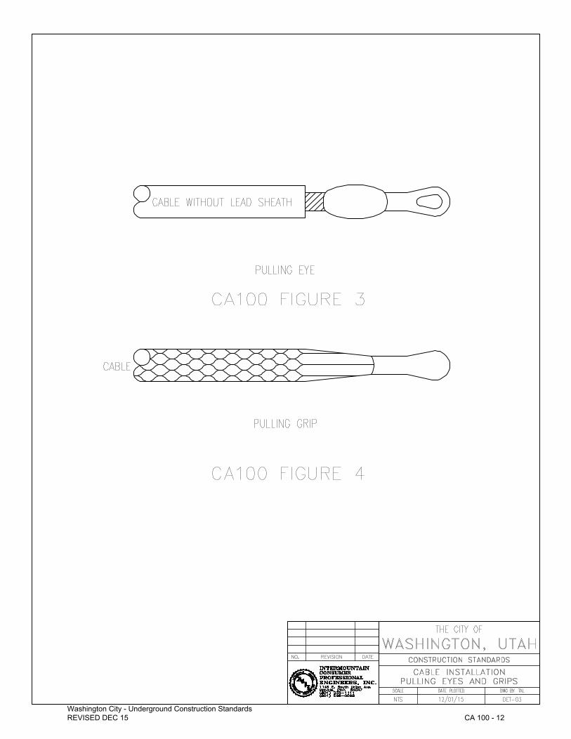
C. Pulling Eyes and Grips
1. Cables shall be pulled into conduit with a pulling eye attached to the cable conductor (see Figure 3) or a pulling grip placed over the cable sheath, insulation or jacket (see Figure 4).
D. Maximum
1. Straight Pulls
(a) When primary or secondary cables are pulled into straight conduit runs, the pulling line tension shall not exceed the values shown in Tables 3 and 4.
E. Vault and Transformer Terminations
1. A minimum of 10 feet of excess cable is required in a vault and transformer basement after termination.

CABLE INSTALLATION Washington City – Underground Construction Standard
CA 100 ‐ 8REVISED DEC 15
TABLE 3 MAXIMUM ALLOWABLE PULLING LINE TENSIONS (LBS)
CONCENTRIC NEUTRAL, URD, PRIMARY CABLES
Conductor Size and Type (1, 3) 1 ‐ Cable Per Conduit Pulling Eye Pulling Grip (2) #1/0 AWG A1. 635 635#4/0 AWG A1. 1270 1000750 MCM A1. 4500 1000Notes: (1) Maximum allowable pulling line tensions are determined by the strength of the conductor and are
not affected by cable voltage rating, etc. (2) The maximum allowable pulling line tensions shown assume the use of a grip on each cable. If one
grip is used for all cables, reduce the values shown by 33%. (3) Verify all pulling tensions with cable manufacturer. Do not exceed manufacturer
recommendations.
TABLE 4 MAXIMUM ALLOWABLE PULLING LINE TENSIONS (LBS)
600 VOLT, SECONDARY CABLES
Conductor Size and Type
1 Cable per Conduit 3 Cables per Conduit 4 Cables per Conduit
Pulling Eye Pulling Grip Pulling Eye Pulling Grip
(1) Pulling Eye Pulling Grip
(1) #1/0 AWG AL. 635 635 1270 1270 1905 1905#1/0 AWG Cu. 845 845 1690 1690 2535 2535#2/0 AWG AL. 800 800 1600 1600 2400 2400#2/0 AWG Cu. 1065 1000 2130 2000 3195 3000#4/0 AWG AL. 1270 1000 2540 2000 3810 3000#4/0 AWG Cu. 1700 1000 3400 2000 5100 3000350 KCMIL AL. 2100 1000 4200 2000 6300 3000350 KCMIL Cu. 2800 1000 5600 2000 8400 3000500 KCMIL Cu. 4000 1000 800 2000 12,000 3000Notes: (1) The maximum allowable pulling line tensions shown assume the use of a grip on each cable. If
one grip is used for all cables, reduce the values shown by 33%.
2. Pull with Bends and/or Sweeps
(a) When primary or secondary cables are pulled into conduit runs including bends or sweeps, the maximum pulling line tension shall not exceed 300 times the radius of curvature of the bend or sweep with the smallest radius expressed in feet.
3.6 BENDING RADII FOR CABLES
A. The minimum bending radii for both single and multiple conductor secondary cables are as shown in Table 5.
TABLE 5 MINIMUM BENDING RADIUS
AS A MULTIPLE OF SECONDARY CABLE DIAMETER (1)
OVERALL DIAMETER OF CABLE, INCHES1 inch and less 1 inch to 2 inch 2 inch and over 12 diameters 15 diameters 15 diameters
B. The minimum bending radii for single conductor high voltage cables shall be 12 times the cable diameter.

CABLE INSTALLATION Washington City – Underground Construction Standard
CA 100 ‐ 9REVISED DEC 15
3.7 BURIAL DEPTH
A. See Cables in Conduit Section CO 100 and Drawings CO 105‐CO 125 for conduit burial depths and details.
3.8 SOIL COMPACTION
A. Over Conduit
1. See Conduit Installation Section CO 100 for compaction requirements.
3.9 MULTIPLE PRIMARY CIRCUITS IN ONE TRENCH
A. When the cables comprising two primary circuits (whether single, two, or three‐phase) are installed in a common trench the horizontal separation between the two circuits (closest cable to closest cable) shall be 12" minimum.
3.10 CLEARANCE TO OTHER UNDERGROUND UTILITIES
A. Water: 5 ft. horizontal Sewer: 5 ft. horizontal Natural Gas: 10 ft. horizontal 1 ft. vertical above or below where crossing Cable TV: 1 ft. horizontal 6" vertical above secondary Phone: 1 ft. horizontal 6" vertical above secondary
END SECTION CA 100

Washington City - Underground Construction Standards REVISED DEC 15
CA 100 - 10

Washington City - Underground Construction Standards REVISED DEC 15
CA 100 - 11
Washington City - Underground Construction Standards REVISED DEC 15
CA 100 - 12

CABLE CAPS Washington City – Underground Construction Standard
CA 200 ‐ 13REVISED DEC 15
SECTION CA 200 ‐ CABLE CAPS PART 1 ‐ SCOPE
1.1 This standard details requirements applicable to cable end caps to seal the ends of primary and secondary cables.
PART 2 ‐ GENERAL
2.1 TEMPORARY CAPS
A. Cable end caps are available for temporarily sealing the ends of primary and/or secondary cables during the period of time between installation of the cables and completion of splices or terminations and during yard storage. In no case shall the cables be left uncapped or unprotected.
2.2 PERMANENT CAPS
A. When the ends of primary and/or secondary cables are to be capped and then buried, left in a manhole or switchgear, etc. for future use they must be capped with cable end caps.
PART 3 ‐ INSTALLATION
3.1 TEMPORARY CAPS
A. Cut the end of the cable to be capped off the described length (square cut).
B. Determine the appropriate cable and cap.
C. If the cable to be capped is a concentric neutral cable, remove the concentric neutral wires from the cable end that is to be capped.
D. Push the cable end cap onto the end of the cable until the mastic in the cap surrounds the cable end (see Figure 1).
3.2 PERMANENT CAPS
A. Cut the end of the cable to be capped off to the desired length (square cut).
B. Determine the appropriate cable end cap for primary and secondary cable.
C. Slip the cable end cap over the cable end.
D. Heat the cable end cap thereby causing it to shrink in diameter and conform to the cable end. This will totally seal the cable end against environmental conditions (see Figure 2).
PART 4 ‐ CAUTIONS AND COMMENTS
4.1 CAUTION:
A. Both the temporary and permanent cable end caps have a voltage rating of 600 volts and must not be used to cap energized primary cables.
4.2 SAFETY
A. Do not shortcut or forget safe working procedures. Regardless of the accuracy of cable labeling, it cannot be relied upon when working and handling cables. The energized status of any individual cable must be tested by proper phasing and testing techniques. Proper cable grounding procedures must be followed.
END SECTION CA 200

Washington City - Underground Construction Standards REVISED DEC 15
CA 200 - 14

Washington City - Underground Construction Standards REVISED DEC 15
CA 200 - 15

CABLE MARKING AND LOCATION Washington City – Underground Construction Standard
CM 100 ‐ 16REVISED DEC 15
SECTION CM 100 ‐ CABLE MARKING AND LOCATION PART 1 ‐ SCOPE
1.1 This specification details the standard method to be used for marking primary and secondary underground cables to indicate the general direction from which each cable extends from a given site.
It also details a method for identifying individual phases in multi‐cable primary and secondary cable systems.
PART 2 ‐ DEFINITIONS
2.1 PRIMARY CABLES
A. All cables with voltage ratings greater than 600 volts.
2.2 SECONDARY CABLES
A. All cables with voltage ratings of 600 volts or less including ground grid conductors.
PART 3 ‐ INSTALLATION
3.1 DIRECTION IDENTIFICATION
A. Primary and secondary cables shall be marked with one tag indicating direction or exit from underground facilities (i.e., vaults, primary junction boxes, service holes, manholes, secondary junction boxes, transformers, or splice boxes). This tag shall indicate the general direction of the cable(s) length of cable and termination point to the next facilities where the cable is located. All tags used must be approved by the Power Department Inspector.
1. All tags will be labeled with next point of connection (i.e. transformer 1 to transformer 2). See attached instruction drawings.
2. All equipment will be numbered as per the instruction drawings prior to tagging the cable in order to be accurate. The tagging will be inspected by the Power Department Inspectors prior to energizing.
Note: Approved tags can be purchased at any Intermountain Farmers outlet.
B. PHASE IDENTIFICATION
1. When individual phases in a primary or secondary multi‐cable installation are to be identified, bands of black tape shall be used. Each phase shall be identified as follows: black for "A" Phase, red for "B" Phase, and blue for "C" Phase. Where multiple bands are used, separate bands by one tape width.
C. TAPE INSTALLATION REQUIREMENTS
1. Width and Thickness
(a) Tape used for phase identification shall be at least three layers of tape thick and should be limited in width to one width of tape.
2. Placement of Tapes on Cables
(a) The tape used for phase identification shall be placed at a convenient and easily visible spot near the point of entrance and exit of cables from a given site. Care shall be taken when tape is placed on concentric neutral primary cables to ensure that the tape is placed over the concentric neutral conductors and that contact between the semiconducting shield under the concentric neutral conductors and the marking tapes is minimized.
CABLE MARKING AND LOCATION Washington City – Underground Construction Standard
CM 100 ‐ 17REVISED DEC 15
D. CABLE IDENTIFICATION
1. Any form of cable identification will not replace color coding requirements. 2. Cable tagging will provide a means of identifying underground cables throughout their length.
Specifically, this requirement includes the following:
(a) Cable phases should be tagged on all terminal poles to correspond with the established overhead phase number.
(b) Care should be taken during the installation of the underground tagging system so that the cable phase identification integrity is maintained.
(c) The correct phase tag number should be placed on the cable whenever the cable is accessible such as in enclosures or splice boxes.
(d) Phasing should be indicated on the construction sketch so that this information can be placed on the permanent maps. This will include, but not be limited to:
(1) Phase identification of cables serving individual transformers. (2) Phase identification of cables at all junction points.
(e) Cable tags must be changed whenever the cable system is changed.
E. SAFETY
1. Do not shortcut or forget safe working procedures. Regardless of the accuracy of cable labeling, it cannot be relied upon when working and handling cables. The energized status of any individual cable must be tested by proper phasing and testing techniques. Proper cable grounding procedure must be followed.
F. Please refer to the following sketches for cable and phase identification examples.
END SECTION CM 100

Washington City - Underground Construction Standards REVISED DEC 15
CM 100 - 18

Washington City - Underground Construction Standards REVISED DEC 15
CM 100 - 19

CONDUIT INSTALLATION Washington City – Underground Construction Standard
CO 100 ‐ 20REVISED DEC 15
SECTION CO 100 ‐ CONDUIT INSTALLATION PART 1 ‐ SCOPE
1.1 This standard outlines installation details for plastic (Type PVC Schedule 40 or better), used in underground distribution.
PART 2 ‐ DEFINITIONS
2.1 PLASTIC CONDUIT
A. PVC conduit shall be PVC Schedule 40 or better.
2.2 BURIAL DEPTH
A. Direct Buried Conduit
1. Vertical distance from the surface under which conduits are installed to the top of the conduit nearest the surface.
B. Concrete Encased Conduit
1. Vertical distance from the surface under which conduits are installed to the top of the concrete envelope surrounding the conduits.
2.3 SWEEP
A. Change in direction of a conduit or group of conduits with an angle of bend of ten (10) degrees or less or a radius of bend of 15 feet or more. Use 36” radius schedule 40 sweeps for all primary installations.
2.4 BEND
A. Change in direction of a conduit or group of conduits that, due to the angle of bend or radius of bend, cannot be defined as a sweep.
PART 3 ‐ APPLICATION
3.1 INSTALLATION APPLICATIONS
A. Table 1 includes information for determining the most acceptable installation method for primary and secondary cable applications. The most acceptable installation methods are prioritized with the number (1) being the most acceptable method.
In the majority of the cases, the installation method designated (1) shall be used. Only if it is totally impossible, as determined by the Power Department Inspector, should the next method be used.
B. All spare conduit shall have mule tape supplied and installed prior to approval.
3.2 CONDUIT SIZES
A. Refer to Table 1 Section CA 100 for determining conduit sizes for primary and secondary conductors.
3.3 Six‐inch (6") warning tape shall be installed 12" below finished grade for the length of the entire trench.

CONDUIT INSTALLATION Washington City – Underground Construction Standard
CO 100 ‐ 21REVISED DEC 15
TABLE 1 CABLE INSTALLATION METHOD
PRIMARY CABLE
SECONDARY CABLE
1 #1 Recommended Method of Installation2 #2 Recommended Method of Installation 3 #3 Recommended Method of Installation 4 #4 Recommended Method of Installation
APPLICATION (1)
PLASTIC CONDUIT STEEL CONDUIT
EXPO
SED
ALUMINUM
CONDU
IT
TRAY
S,
THRO
UGHS,
AND WIREW
AYS
DIRE
CT
BURIED
CONCR
ETE
ENCA
SED
DIRE
CT
BURIED
CONCR
ETE
ENCA
SED
EXPO
SED
FREEWAY CROSSING 1 1 3 3 2 2
PARALLEL TO AND BENEATH FREEWAYS 1 1 3 3 2 2
HIGHWAY AND MAIN THOROGHFARE ARE CROSSINGS 1 1 2 2 3 3 4 4
PARALLED TO AND BENEATH HIGHWAYS AND MAIN THOROUGHFARES
1 1 2 2 3 3 4 4
PAVED RESIDENTIAL STREET, UNPAVED RESIDENTIAL STREET, UNPAVED ROAD CROSSINGS
1 1 2 2 3 3 4 4
PARALLEL TO AND BENEATH PAVED RESIDENTAIL STREETS, UNPAVED STREETS, OR UNPAVED ROADS
1 1 2 2 3 3 4 4
LARGE COMMERCIAL AREAS 4 4 1 1 3 3 2 2
SMALL COMMERCIAL AREAS 1 1 2 2 3 3 4 4
ADJACENT TO PAVED SURFACES OF FREEWAYS, HIGHWAYS, MAIN THOROUGHFARES, AND RESIDENTAIL STREETS
1 1 2 2 3 3 4 4
PARKING LOTS WITH ASPHALY OR CONCRETE SURFACE 1 1 2 2 3 3 4 4
LANDSCAPE AREAS: 1. ORDINARY (GRASS, FLOWERS, SHRUBS,
ETC.)
1 1 2 2 3 3 4 4
2. EXOTIC (DECORATIVE FOUNTAINS, EXPENSIVE FOWER BEDS, ETC.)
1 1 2 2 3 3 4 4
UNIMPROVED AND UNLANDSCAPED AREAS 1 1 2 2 3 3
UNDERBUILDINGS (3) 1. CONCRETE FLOORS
1 1 2 2
2. FLOORS OTHER THAN CONCRETE 1 1 2 2
WITHIN BUILDING WALLS (2) 1. CONCRETE OR BRICK WALLS
22
22
12
12
2. WALLS OTHER THAN CONCRETE OR BRICK
1 1 2 2
ATTACHED TO BUILDING (3) 1. EXTERIORS
1 1 2 2
2. INTERIORS 1 2
TRANSFORMER VAULTS OR ROOMS INCLUDING THOSE IN PUBLIC OR PRIVATE
4 4 1 1 3 3 2 2
NOTES: (1) FOR APPLICATIONS NOT SHOWN IN THIS TABLE, CONTACT THE CITY POWER DEPARTMENT.(2) BRICK OR CONCRETE WALLS, WITHIN WHICH CONDUITS ARE INSTALLED, MUST PROVIDE A 2‐INCH (MINIMUM) ENVELOPE OF
BRICK OR CONCRETE AROUND THE CONDUIT. IF A 2‐INCH ENVELOPE IS NOT PROVIDED, ADDITIONAL BRICK OR CONCRETE MUST BE ADDED TO INCREASE THE ENVELOPE TO 2‐INCHES.
(3) SPECIAL APPROVAL MUST BE OBTAINED FROM THE CITY POWER SUPERINTENDENT BEFORE ANY HIGH VOLTAGE CABLE IS INSTALLED WITHIN A BUILDING ENVELOPE OR ATTACHED TO THE BUILDING.

CONDUIT INSTALLATION Washington City – Underground Construction Standard
CO 100 ‐ 22REVISED DEC 15
PART 4 ‐ INSTALLATION
4.1 BURIAL DEPTH
A. The minimum allowable burial depths for direct buried and concrete‐encased conduits are shown in Table 2.
TABLE 2 INSTALLED UNDER
PAVED SURFACE ALL OTHER LOCATIONS
Direct Buried Concrete Encased Direct Buried
Concrete Encased
SCH 40 PVC Conduit With Secondary Cables 32 Inches See Note 32 Inches See Note
SCH 40 PVC With Primary Cables 42 Inches See Note 42 Inches See Note
Note: If, in a particular installation, burial depths less than those permitted by the table above are not possible, reduced burial depths must be approved by the City Power Department.
4.2 TRENCHES FOR CONDUITS
A. Trench Bottoms
1. When conduits are direct buried or concrete encased, the bottom of the trench into which the conduits are placed shall be free from rocks exceeding 1 inch in their largest dimension. When the trench bottom contains rocks exceeding this size requirement, the trench shall be excavated 6 inches deeper than the burial depth required for the conduits and then backfilled to the required burial depth with sand or screened backfill.
B. Trench Backfill
1. Direct Buried Plastic Conduit
(a) At least 6 inches of sand or 1 inch minus material shall be placed over the conduits. The remaining backfill shall be spoil removed from the trench unless specific backfill requirements exist.
2. Concrete‐Encased Plastic Conduit
(a) The material used to backfill trenches containing concrete‐encased steel or plastic conduits shall be spoil removed from the trench unless specific backfill requirements exist.
3. Drying Time for Concrete Before Backfilling
(a) Backfill shall not be placed in trenches containing concrete‐encased conduits until the concrete has been allowed to set for at least 24 hours.
C. SOIL COMPACTION
1. When backfill placed over direct buried plastic conduit must be compacted, machine compacting shall not be used within 12 inches of the conduits. For concrete‐encased plastic or steel conduits, machine compaction may be used without restriction on proximity to the concrete envelope.
2. Placement and Compaction: Place and compact backfill and fill materials in layers of 8 inch maximum lifts. Thinner lifts may be required depending on materials and compaction effort.
3. Before compaction, moisten and aerate each layer as necessary to provide optimum moisture content. Compact each layer to required percentage of maximum dry density or relative dry density for each area classification specified below. Do not place backfill or fill material on surfaces that are muddy, frozen, or contain frost or ice.
CONDUIT INSTALLATION Washington City – Underground Construction Standard
CO 100 ‐ 23REVISED DEC 15
4. Place backfill and fill materials evenly adjacent to structures, piping, and equipment to required elevations. Prevent displacement of raceways and equipment by carrying material uniformly around them to approximately same elevation in each lift.
5. Compaction: Control soil erosion during construction, providing minimum percentage of density specified for each area classification indicated below.
(a) Percentage of Maximum Density Requirements: Compact soil to not less than the following percentages of maximum density for soils which exhibit a well‐defined moisture‐density relationship (friction‐cohesive soils), determined in accordance with ASTM D 1557.
(1) Areas Under Structures, Building Slabs, Walks and Steps, Pavements: Scarify and compact top 12 inches of subgrade and each layer of backfill or fill material to 95 percent maximum density for friction‐cohesive material.
(2) Other Areas: Scarify and compact top 6 inches of subgrade and each layer of backfill or fill material to 90 percent maximum density for friction‐cohesive soils.
(b) Moisture Control: Where subgrade or layer of soil material must be moisture conditioned before compaction, uniformly apply water. Apply water in minimum quantity necessary to achieve required moisture content and to prevent water appearing on surface during, or subsequent to, compaction operations.
(c) The Contractor is responsible for the ultimate success of the compaction effort and overall project quality control.
6. Subsidence: Where subsidence occurs at electrical installation excavations during the period 12 months after the project completion, remove surface treatment (i.e., pavement, lawn, or other finish), add backfill material, compact to specified conditions, and replace surface treatment. Restore appearance, quality, and condition of surface or finish to match adjacent areas.
D. GRADING OF CONDUITS
1. When conduits are installed between manholes, they shall be graded to drain towards the manholes whenever possible. The minimum slope necessary to accomplish this is 3 inches per 100 feet of conduit.
E. CONDUIT SPACERS
1. Installation Requiring Use of Conduit Spacers
(a) When two or more conduits are encased in concrete, base and intermediate spacers shall be used to maintain conduit spacing during installation of the concrete envelope. When four or more conduits are direct buried, base and intermediate spacers shall be installed to maintain conduit spacing during the backfill operation.
2. Minimum Separating Between Conduits
(a) Conduit Spacers shall provide a minimum edge to edge separation between conduits of 3 inches.
F. CONCRETE ENVELOPE REQUIREMENTS
1. Minimum Envelope Dimension
(a) When conduits are encased in concrete, they shall be enclosed by a concrete envelope as shown in Figure 1.
2. Concrete
(a) A 3/4" minus 2500 PSI mix as per ASTM C94 specifications. In all cases, a Type 2 modified or Type 5 cement will be used. It should be wet enough to flow easily into the spaces around the conduits, but not so fluid as to float the conduits. Concrete shall be spaded or vibrated to ensure that the spaces around the conduits are filled.

CONDUIT INSTALLATION Washington City – Underground Construction Standard
CO 100 ‐ 24REVISED DEC 15
3. Conduit Retention
(a) Weights of approximately 75 pounds or other means may be used to prevent conduits from floating during pouring of the concrete envelope.
G. CONDUIT BENDS AND SWEEPS
1. Minimum Radius
(a) Bends
(1) The minimum radius of bends in conduits shall not be less than 15 times the diameter of the largest conduit being installed. If smaller minimum bending radii are required, they shall not be less than the minimum bending radii of the cables to be installed in the conduits. PVC Schedule 40 or 80 elbows shall be used for bends.
(2) Service conduit shall include a 90° fitting at the meter and a 45° fitting at the secondary box.
(3) Heated conduit bends will have no burn or tan marks. There shall be no ovaling of the conduit.
(b) Sweeps
(1) The maximum angle of sweeps in conduits shall be 11 degrees. When the sweep is greater than 11 degrees, PVC Schedule 40 will be required.
2. Bend and Sweep Construction
(a) Sweeps shall be made by bending 10 foot lengths of plastic conduit. Bends shall be made using PVC Schedule 40 or 80 elbows.
(b) To reduce damage to PVC elbows, a wire rope shall be used to pull the cable through the conduit.
3. Conduit bend and elbow sizes greater than 2‐inch diameter will be concrete thrust blocked or encased in concrete for the full length of the bend or elbow.
4. Ninety degree (90°) bends made into 200 amp equipment ground sleeves shall be constructed with 45 degree long radius, Schedule 40 PVC elbows. This requirement is made in order to allow more cable distance between the connection elbow and the conduit.
5. Ninety degree (90 ̊) upward bends will not be used for 600 amp equipment ground sleeves. The straight conduit will run directly into the 600 amp ground sleeve with no upward bend. The cable will be pulled into the ground sleeve and trained up to the equipment connections.
H. SHORING, LAYING BACK, SPOIL PLACEMENT AND RETENTION
1. When employees must enter a trench to install conduits, the trench shall be shored or laid back and the spoil shall be effectively retained and placed back from the edges of the trench as required by local, state and national codes or ordinances to ensure that the employees are not subject to moving ground or cave‐ins.
I. CONDUIT REPAIR
1. If after installation a conduit is damaged due to construction or excavation, a full stock length (usually 10 foot segments) will be used to repair damaged section. Repair collars will not be allowed.
J. RISER POLE CONDUIT
1. Conduits for riser pole shall be rigid steel and shall continue up the pole from the rigid elbow to within the last 10 feet of rise. The riser pole conduit shall be straight and supported with a unistrut system. Any crooked or misaligned conduits will not be accepted. All steel conduit below grade shall be plastic coated or wrapped with moisture barrier tape.
END SECTION CO 100

Washington City - Underground Construction Standards REVISED DEC 15
CO 100 - 25

ENCLOSURE INSTALLATION Washington City – Underground Construction Standard
EN 125 ‐ 26REVISED DEC 15
SECTION EN 125 ‐ ENCLOSURE INSTALLATION PART 1 ‐ SCOPE
1.1 This standard outlines installation details for primary enclosures (transformers, switchgear, primary junctions, manholes, splice boxes, etc.) used in underground distribution.
PART 2 ‐ INSTALLATION
2.1 INSTALLATION
A. Above Ground Primary Enclosures
1. Ground Sleeve Installation Depth
(a) The ground sleeve shall be installed with the top being no less than 2" above finished grade.
2. Pad Installation Depth
(a) The mounting pad shall be placed on the finished grade.
B. Location
1. Primary enclosures shall be located such that adjacent obstacles such as fences, buildings, etc. do not interfere with operation, installation, or maintenance of the enclosures.
2. Clearance in front of all enclosures shall be 10ft. Planting of trees, shrubs, gardens that interfere with the safe operation of the enclosure shall be removed.
2.2 IDENTIFICATION
A. Equipment stenciled marking shall be no less than 2 inch letters.
B. Stencil and paint shall be used for transformer and other equipment I.D.
C. Use of marking pens or stickers is not allowed.
END SECTION EN 125

EQUIPMENT AND LINE LOCATION AND ROW REQUIREMENTSWashington City – Underground Construction Standard
GE 100 ‐ 27REVISED DEC 15
SECTION GE 100 ‐ EQUIPMENT AND LINE LOCATION AND ROW REQUIREMENTS PART 1 ‐ SCOPE
1.1 This standard outlines the location, with respect to property lines, of underground distribution facilities. See location drawings contained in these specifications.
PART 2 ‐ BACK LOT LINES INSTALLATION
2.1 Installations along back lot lines will not be allowed without review by the Power Department Director or Superintendent.
PART 3 ‐ ROW REQUIREMENTS
3.1 Before any power system design approval, the property owner or developer will be required to grant Washington City the proper easements and rights‐of‐way. These will be shown on the as builds when submitted.
A. The standard requirements are as follows:
1. Residential
(a) 10 feet on the front of each lot or parcel 7.5 feet on the sides and back of each lot or parcel
2. Multibuilding or Condominium
(a) 15 feet on the front of each lot or parcel 7.5 feet on the side and back of each lot or parcel (b) (See location drawings contained in these specifications.)
3. Common areas
(a) The equipment (i.e., transformers, vaults, switches) will be placed along access roads as per standards. If placement along access roads cannot be accomplished as determined by the Power Department, equipment will be placed with at least 10 feet of clearance from any permanent structure.
B. All power equipment will be designed and installed as per the location drawings contained in these specifications (Drawings GE101 ‐ GE104) in order to assure equipment falls within the established rights‐of‐way and easements and to maintain consistency of equipment placement throughout the City.
END SECTION GE 100

PRIMARY JUNCTION INSTALLATION Washington City – Underground Construction Standard
PJ 500 ‐ 28REVISED DEC 15
SECTION PJ 500 ‐ PRIMARY JUNCTION INSTALLATION PART 1 ‐ SCOPE
1.1 This standard outlines installation details applicable to Fused 15 kV, 200 and 600 Ampere Primary Junction Installation.
PART 2 ‐ INSTALLATION
2.1 GROUND SLEEVE
A. All single phase padmount transformers that are placed as loop feed or may at some time need to change phase wire or otherwise make wire location movement within the transformer compartment will have a ground sleeve. Concast FC‐40‐44‐24‐2618(5) or FC‐42‐42‐24‐1326(6) or approved equal. See attached detail sheet. All three‐phase transformers will be placed on the transformer pad detail shown on Drawing UT 185. The pad may be pre‐constructed or poured in the field. Any field design must be inspected before concrete is poured to ensure rebar support.
For all 600 amp equipment (i.e., switches, vaults), a 6' x 8' x 6' (inside dimensions) ground sleeve (PJ525) will be installed under the equipment. The approved City detail (Figure 3) will be used for this ground sleeve.
B. SWITCHING/FUSING EQUIPMENT
1. Switching and/or fusing requirements for any industrial/commercial facility will be reviewed, coordinated and approved by the City Power Department. Sectionalizers will be required for any tap off the City's Main Distribution that has the potential of servicing more than one commercial/industrial or large residential location or more than one circuit/feeder. Fusing will be determined by the Power Director and each subdivision or development will be fused according to the needs. Two sets of fuses will be supplied by the developer. The first commercial/industrial developer that requests power service into a new development which has the potential for more than one location or circuit/feeder will be required to install and pay for sectionalizing equipment and then upon energizing this equipment will become the property of Washington City.
2. Switching and/or fusing requirement for any subdivision or residential development will be reviewed, coordinated and approved by the City Power Director. As a general outline, the first tap of the City's Municipal Distribution for a subdivision/residential development will not require a sectionalizer if the total connected load is less than 300 kVA and provided there is an overhead feeder connection available. If the first tap is for a load greater than 300 kVA or an overhead connect is not available, a sectionalizer must be installed and paid for by the development. Any development requiring service off an existing underground system must install and pay for sectionalizing equipment if the additional load causes the total load to exceed 300 kVA. These guidelines will also apply to single‐phase industrial/commercial facility development.
3. The Power Department may require, at its sole determination, switching and/or fusing equipment to be installed in order to maintain proper system reliability, and load transfer backup capabilities. Future system needs shall also be used in determining the number and type of switching and fusing equipment that may be required.
4. Switching and fusing equipment locations and type required are to be coordinated with cable loading and looping requirements as outlined in Standard CA100.
5. Connection to existing sectionalizer or switch gear equipment will be subject to a fee based on the connection type and connection fees will be determined by the Power Department Director.
C. Grounding/Neutral Bus
1. A #4/0 copper neutral bus will be provided for all 600A equipment.

PRIMARY JUNCTION INSTALLATION Washington City – Underground Construction Standard
PJ 500 ‐ 29REVISED DEC 15
2. A #2/0 copper neutral bus will be provided for all 200A equipment.
D. Identification
1. Provide equipment ID using stencil and paint. No marking pens or stickers will be allowed.
PART 3 ‐ TESTING BEFORE ENERGIZING
3.1 LOADBREAK ELBOWS AND INSULATING RECEPTACLES
A. Primary Junction Installations, which include loadbreak elbows and/or insulating receptacles, shall be operated before the installation is energized to ensure that there is no interference from concentric neutral conductors, adjacent elbows, etc.
3.2 SWITCHES
A. Test operate all switches in Fused, Primary Junction Installations to ensure that adjacent obstacles such as fences, walls, etc. do not interfere with the switch operating handle.
PART 4 ‐ LOCATION
4.1 Primary Junction Installations shall be located such that adjacent obstacles such as fences, buildings, etc. do not interfere with operation, installation and maintenance of the installation.
END SECTION PJ 500

Washington City - Underground Construction Standards REVISED DEC 15
PJ 500 - 30

Washington City - Underground Construction Standards REVISED DEC 15
PJ 500 - 31

Washington City - Underground Construction Standards REVISED DEC 15
PJ 500 - 32
PRIMARY VAULT SPECIFICATIONS Washington City – Underground Construction Standard
PV 100 ‐ 33REVISED DEC 15
SECTION PV 100 ‐ PRIMARY VAULT SPECIFICATIONS PART 1 ‐
1.1 THREE PHASE ABOVE GROUND PRIMARY VAULT, WITH FIBERGLASS SLEEVE OR EQUIVALENT
A. 3‐phase or 1‐phase above ground primary junction fiberglass vault with fiberglass sleeve
B. Units must meet the following specifications:
1. Penta head bolts on lid. 2. All hardware including hinges to be stainless steel. 3. Color – Green, desert tan, or willow green. 4‐Way Junction required.
C. Approved Vendors:
1. P.D.I. or equivalent full fiberglass 4 ways (green or tan).
(a) 3 phase PDI # CJP‐31‐50‐L2‐MG‐4025. (b) 1 phase PDI # CJP‐10‐49‐L2‐MG‐4026.
1.2 VAULTS WILL INCLUDE:
A. Three four‐point junctions installed Cooper #2637164C13M, standoff bracket and necessary receptacles. The unit is to be mounted on ground sleeve #QF60‐18039, 60 X 18 X 30 quality fiber glass. (Or equivalent in design).
END SECTION PV 100

SECONDARY JUNCTION INSTALLATION Washington City – Underground Construction Standard
SJ 100 ‐ 34REVISED DEC 15
SECTION SJ 100 ‐ SECONDARY JUNCTION INSTALLATION PART 1 ‐ SCOPE
1.1 This standard describes the installation of secondary junction boxes and mobile home park meter pedestals.
PART 2 ‐ INSTALLATION
2.1 BURIAL DEPTHS
A. Secondary Junction Boxes
1. Top of secondary junction boxes shall be installed with base 2 inches above final grade.
(a) Small secondary junction box (Carson 1220‐27). (b) Large secondary junction box (Nordic PSP‐151530‐MG).
B. Mobile Home Park Metering Pedestals
1. Mobile home park metering pedestals shall be installed to the depth indicated on the pedestal.
PART 3 ‐ SAFETY
3.1 LOCKING
A. Secondary Junction Boxes
1. All secondary junction boxes shall be locked with pedestal equipment locks. Standard tumbler‐type locks or other devices are not approved for this application.
B. Mobile Home Park Meter Pedestals
1. The access panel to the unmetered bus in all mobile home park meter pedestals shall be locked with pedestal equipment locks.
END SECTION SJ 100

STREETLIGHT INSTALLATION Washington City – Underground Construction Standard
SL 100‐ 35REVISED DEC 15
SECTION SL 100 ‐ STREETLIGHT INSTALLATION PART 1 ‐ SCOPE
1.1 This standard outlines the requirements for installing street lights erected in the City.
PART 2 ‐ EQUIPMENT SPECIFICATIONS/INSTALLATION
2.1 POLICY
A. It is the policy of the City that all streetlights erected in the City, whether in a public easement, in an easement to be dedicated to the City within the City limits, in a new or proposed subdivision or in building projects requiring street improvement, the following shall be adhered to.
2.2 PURPOSE AND OBJECTIVE
A. To ensure streetlights are installed according to uniform construction guidelines and equipment specifications.
2.3 PROCEDURES AND RESPONSIBILITIES
A. The lights shall be mounted on an aluminum or galvanized steel, single member arm pole designed to withstand 100‐mile‐per‐hour wind (certified). All poles shall have an access hole at or near the base for access to the wiring. The overhang shall not exceed 25% of the mounting height. The following is the guideline to be used for plat preparation:
Road Width Mounting Height Lamp Wattage Pole Spacing 35‐45’ 35’ 200 250‐300’ 46‐62’ 40’ 250 250’63‐72’ 40’ 400 250’
B. This may be subject to change as determined by the Power Department Inspector as per any safety
requirements or instructions. All arms shall be 2 3/4" O.D. (2" pipe) laminar mounting. All poles shall be anchor base poles and the foundation design shall be adequate for the length of pole, the arm that's being installed, the soil conditions and the 100‐mile‐per‐hour winds. (As determined by the Utility Engineer). They will be Crouse‐Hinds OVM Swing‐Down Roadway Lighting or approved equal as determined by the Power Department Inspector.
1. All street lights will be inductive lighting as per City code.
C. If a subdivision or project has a 50' wide road and would like a more aesthetic light, they may order the Crouse‐Hinds RCL successor cutoff laminar, Catalog Number REL15SP23D4‐150 Watt with the square pole and arm or an approved equal as determined by the Power Department Inspector.
D. Where streetlights are placed in the sidewalk or back of sidewalk, the foundation base will be made level with the sidewalk grade. The one foot of base shown above grade on the drawing will be eliminated.
E. All streetlight poles placed next to or near a roadway will be a breakaway base type.
F. Breakaway poles are required when the pole is placed within 4 feet of the curb and gutter. Where curb and gutter do not exist, transportation clear zone requirements will be met. For these requirements, contact the City Utilities Director.

STREETLIGHT INSTALLATION Washington City – Underground Construction Standard
SL 100‐ 36REVISED DEC 15
PART 3 ‐ INSTALLATION OF NONSTANDARD STREETLIGHTS
3.1 If a subdivision or project has been allowed in the past, prior to adoption of this policy, to install nonstandard streetlights, the project owner may continue to install the nonstandard streetlights with the exception that a high pressure sodium lamp must be used. If a homeowners' association or similar party will agree in writing to maintain a proposed streetlight system, nonstandard streetlights may be installed with the inductive lamps. A contract for maintenance may be entered into with the City for private nonstandard street lighting. Nonstandard street lights and any contract for maintenance whether public or private streets must be approved by the City Council and the Utilities Director to ensure public safety. Maintenance concerns will be addressed to the Council by the Power Director upon application to the Council for any nonstandard street light installation.
PART 4 ‐ OWNERSHIP
4.1 Streetlights shall be installed at the developers expense in new/proposed subdivision and projects. Upon the recommendation by the Utilities Director, and with the approval of the City Council the Power Department shall install additional street lights in existing subdivisions at $1,200.00 each if power is readily available. If power is not available at this location a cost estimate will be presented to the customer or group of customers having an interest in street light installation. The cost for the installation must be paid in full prior to the installation.
PART 5 ‐ FOOTING SPECIFICATION
5.1 A typical footing specification is included with these specifications. However, the customer is responsible for assuring that any given footing will meet the wind loading levels at a given site as well as soil conditions.
PART 6 ‐ STREETLIGHT WIRE AND DISTANCE LOADING
6.1 Streetlights connected to a specific wire size shall meet the following guide lines.
SECONDARY WIRE SIZE FOR STREET LIGHTS 120/240 VOLT
SUBDIVISION
# LIGHTS MAX DISTANCE FROM SOURCE WIRE SIZE
(COPPER)
1
2
3
4
5
6
400’
1000’
1200’
1200’
1200’
1200’
#10 Romex
#6 single strand
#6 single strand
#6 single strand
#6 single strand
#6 single strand
END OF SECTION SL 100

CABLE SPLICES Washington City – Underground Construction Standard
SP 100 ‐ 37REVISED DEC 15
SECTION SP 100 ‐ CABLE SPLICES PART 1 ‐ SCOPE
1.1 This standard outlines installation details for primary and secondary cable splices used in underground distribution.
PART 2 ‐ INSTALLATION
2.1 INSTALLATION INSTRUCTIONS
A. General
1. Primary or secondary cable splices will not be allowed within conduit runs.
B. Primary Cable Splices
1. Primary cable splices shall be installed in accordance with installation instructions provided by the manufacturer. The concentric neutral conductors shall be connected together with compression connectors.
2. After splice has been installed, the integrity of the pre‐jacket shall be maintained. 3. Primary cable splice locations must be approved by the City Power Department prior to
installation.
C. Secondary Cable Splices
1. Installation instructions for secondary cables are as follows:
(a) Remove cable insulation from cable ends to the dimension required for the compression connector being used.
(b) Slide heat or mechanical shrinkable sleeve of appropriate size over one of the conductor ends until the bare conductor is visible.
(c) Connect the conductor ends with the appropriate compression connector. (d) Slide the heat shrinkable sleeve along the cable until it is over the compression connector. (e) Apply heat to the heat shrinkable sleeve until it shrinks in size to encapsulate and seal the
cable ends and the compression connector.
2.2 INSTALLATION PRECAUTION
A. When splices are to be installed on a cable(s) that have been exposed to moisture, the cables must be cut back until the moisture is eliminated.
END SECTION SP 100

CABLE TAPS (200 AMPS) Washington City – Underground Construction Standard
TA 100 ‐ 38REVISED DEC 15
SECTION TA 100 ‐ CABLE TAPS (200 AMPS) PART 1 ‐ SCOPE
1.1 This standard outlines installation details for 200 ampere, 15 kV loadbreak junctions used in underground distribution.
PART 2 ‐ INSTALLATION
2.1 GENERAL
A. 200 ampere, 15 kV loadbreak junctions must be installed in primary enclosures. They are not suitable for direct burial. All elbows and taps will be supplied from one of the following manufacturers and will meet the current City standard:
1. 3‐M 2. Elastimold 3. Blackburn
B. All silicon used during elbow and tap installation will be supplied from one of the following manufacturers and will match the stock number:
1. Blackburn (#5SL) 2. Dowell Corning
C. Other silicon brands will not be accepted and will be rejected upon inspection.
2.2 TESTING BEFORE ENERGIZING
A. Operate loadbreak elbows and insulating receptacles before energizing 200 ampere, 15 kV loadbreak junction installations to ensure that:
1. They can be operated without interference from concentric neutral conductors, adjacent elbows, etc.
2. The mounting location of the loadbreak junction is such that rings and covers or doors of primary enclosures, adjacent junctions, etc. do not interfere with their operation.
3. Phasing on Buss shall be Left Source to Right Load; Left A phase to Right C Phase.
END SECTION TA 100

CABLE TAPS (600 AMPS) Washington City – Underground Construction Standard
TA 600 ‐ 39REVISED DEC 15
SECTION TA 600 ‐ CABLE TAPS (600 AMPS) PART 1 ‐ SCOPE
1.1 This standard outlines installation details applicable to 15 kV, 600 ampere splice‐tap configurations used in underground distribution systems.
PART 2 ‐ INSTALLATION
2.1 GENERAL
A. 600 ampere, 15 kV elbows and taps must be installed in primary enclosures. They are not suitable for direct burial. All elbows and taps will be supplied from one of the following manufacturers and will meet the current City standard:
1. 3‐M 2. Elastimold 3. Blackburn
B. All silicon used during elbow and tap installation will be supplied from one of the following manufacturers and will match the stock number:
1. Blackburn (#5SL) 2. Dowell Corning
C. Other silicon brands will not be accepted and will be rejected upon inspection.
D. When assembling 15 kV, 600 ampere splice‐tap configuration, a spanner wrench may be used to facilitate installation or removal of connector plugs and reducing tap wells (with or without studs).
PART 3 ‐ CAUTIONS
3.1 Some existing 15 kV, 600 ampere splice‐tap, reducing tap plugs (Fig. 1), and/or deadbreak/deadmake elbows (Fig. 2), look very similar to loadbreak devices. Deadbreak/deadmake devices are suitable for operation only when de‐energized.
END SECTION TA 600

Washington City - Underground Construction Standards REVISED DEC 15
TA 600 - 40

SECONDARY LINE AND METER INSTALLATION FOR RESIDENTIAL SUBDIVISIONSWashington City – Underground Construction Standard
US 100 ‐ 41REVISED DEC 15
SECTION US 100 ‐ SECONDARY LINE AND METER INSTALLATION FOR RESIDENTIAL SUBDIVISIONS PART 1 ‐ SCOPE
1.1 This standard outlines minimum requirements for the service equipment, service conductors, etc., purchased and normally installed by the customer from the secondary junction box to and including the meter.
PART 2 ‐ APPLICATION
2.1 GENERAL
A. This standard shall be used as a guideline for determining whether or not the service equipment, service conductors, etc. that comprise the secondary service meet all applicable national, state and local codes and ordinances and the City Power Department requirements.
2.2 SERVICE CONNECTION CRITERIA
A. Services inspected by Inspecting Authority
1. Underground services shall not be connected to the City's Power Department system until:
(a) Inspections and Connections requiring a minimum of 48 hours’ notice on each are complete. (b) The Power Department Inspector has certified that the service is in compliance with
applicable local, state and national codes and policies. (c) All service installations shall comply with the NEC.
PART 3 ‐ DEFINITIONS
3.1 SERVICE EQUIPMENT
A. The equipment, containing the disconnecting means and overcurrent protective devices, located near the point of entrance of supply conductors to a building, and intended to constitute the main control and means of cutoff of the supply to a building.
B. Buildings shall have an exterior main disconnect.
3.2 UNDERGROUND SERVICE CONDUCTORS
A. The underground supply conductors that extend from the City's secondary junction box to the customer's service and metering equipment.
3.3 GROUNDING ELECTRODE
A. EUFerground shall be used as the grounding electrode. When a metal underground water pipe system is available on the premises, the water pipe system and the ground rod shall be used as grounding electrodes (refer to the NEC for additional requirements).
3.4 GROUNDING ELECTRODE CONDUCTORS
A. The conductors used to connect the grounding electrode(s) to the grounded conductor of the underground service.
3.5 BURIAL DEPTH
A. Where underground Service Conductors are installed in conduits with supplemental protective covering or in raceways, the vertical distance from the surface under which the conduit, supplemental protective covering or raceway is installed to the portion of the conduit, supplemental protective covering or raceway nearest the surface.

SECONDARY LINE AND METER INSTALLATION FOR RESIDENTIAL SUBDIVISIONSWashington City – Underground Construction Standard
US 100 ‐ 42REVISED DEC 15
3.6 METERING PROVISIONS
A. The enclosures, meter sockets, switch boxes, conduit, conduit elbows, etc. required to provide a place for mounting NEMA 3R deadfront‐type meters, required for measuring usage of electrical energy.
B. Meter shall be located within 10 ft. of the front edge of the building.
3.7 SERVICE RISER
A. Steel conduit, conduit elbow, etc. that extend from the bottom of the service trench to the meter mounting provisions and main disconnecting means and enclose the service conductors.
B. Exposed service conduit shall be attached to building using unistrut or equivalent system.
3.8 SERVICE CONDUIT
A. Plastic or steel conduit into which underground service conductors are pulled, excluding service risers.
PART 4 ‐ CODES
4.1 INSTALLATION
A. Underground services shall be installed in accordance with applicable City Power Department requirements and local, state and national codes and ordinances.
4.2 EQUIPMENT AND CONDUCTORS
A. All equipment and conductors installed shall meet or exceed applicable City Power Department requirements and local, state and national codes and ordinances.
PART 5 ‐ INSTALLATION
5.1 UNDERGROUND SERVICE CONDUCTORS
A. Burial Depths
1. The minimum burial depth underground service conduits shall be 32 inches.
B. Type
1. All underground service conductors shall be type USE.
C. Protection
1. Underground service conductors are to be protected from physical damage, by installation in conduit (PVC Schedule 40 or better).
D. Splices
1. Underground service conductors shall not be spliced.
E. Installation Methods
1. In conduit
(a) When underground service conductors are pulled in conduit, care shall be taken to ensure that they are not damaged during the pulling operation.

SECONDARY LINE AND METER INSTALLATION FOR RESIDENTIAL SUBDIVISIONSWashington City – Underground Construction Standard
US 100 ‐ 43REVISED DEC 15
F. Grounding Requirements
1. A grounding electrode shall be connected, via grounding electrode conductors, to the underground service conductors (grounded conductors only) on the line side of and/or within the service disconnecting means.
G. Size
1. The underground service conductors shall have adequate ampacity to carry the load requirements of the premises served by the conductors. The Power Department requires that all services less than 124 Amps be served by #1/0 Aluminum conductor and services between 125‐199 Amps be serviced by #2/0 Aluminum conductor. Above 200 Amps, the service conductor will be #4/0 aluminum conductor. Larger sizes may be required if the service size exceeds the ampacity ratings of the sizes indicated above.
5.2 SERVICE EQUIPMENT
A. Continuous Current Rating
1. All service equipment shall have a minimum current rating of 60 ampere.
B. Short Circuit Current Rating
1. Service equipment and its overcurrent protective devices shall have short circuit current ratings greater than or equal to the short circuit current available at their supply terminals.
5.3 SERVICE DISCONNECTING MEANS
A. All service disconnecting means shall have a current rating of not less than 60 amperes.
B. When multiple switches or circuit breakers are used as the disconnecting means, their combined current rating shall not be less than 60 amperes.
5.4 SERVICE CONDUIT
A. General
1. Service conduit installations shall be carefully designed (length, number of bends, bend radii, etc.) to ensure that the underground service conductors can be pulled into them without damage.
B. Burial Depth
1. Minimum burial depths for service conduits shall be 32 inches.
C. Trench Requirements
1. Trench Bottoms
(a) When conduits are direct buried or concrete encased, the bottom of the trench into which the conduits are placed shall be free from rocks exceeding 1 inch in their largest dimension. When the trench bottom contains rocks exceeding this size requirement, the trench shall be excavated 6 inches deeper than the burial depth required for the conduits and then backfilled to the required burial depth with sand or screened backfill.
2. Trench Backfill
(a) Direct Buried Plastic Conduit
(1) At least 6 inches of 1‐inch minus backfill shall be placed over the conduits. The remaining backfill shall be spoil removed from the trench unless specific backfill requirements exist.

SECONDARY LINE AND METER INSTALLATION FOR RESIDENTIAL SUBDIVISIONSWashington City – Underground Construction Standard
US 100 ‐ 44REVISED DEC 15
5.5 METERING PROVISIONS A. General
1. Typical requirements for meter mounting provision for residences are shown on drawings included in this specification. When meter mounting provisions different from those shown are required, specific metering provision requirements shall be detailed by the City Power Department.
2. The meter mounting provision must be installed in a true vertical plane. 3. Meter mounting provisions with extruded or cast aluminum meter jaws shall not be used. 4. Remote metering will not be allowed for new construction or rebuild/add‐on construction jobs
for fire safety reasons. 5. Meter lock rings shall be supplied by contractor for temporary and permanent meter installation.
B. Location
1. Meters shall not be located in carports, breezeways, covered or screened porches, or other areas that might be enclosed at some future date.
2. The area on either side of a door or swinging window equal to the width of the door or swinging window is unacceptable as a meter location.
3. A level standing and working surface 30" x 30" shall be provided in front of all meters, permitting ready access to the meter.
4. The meter should be installed at the closest point practical to the City Designated Power Service line as indicated on approved plans, however the meter must be installed within 10ft. of the front edge of the building for radio read and service accessibility.
5. The service entrance equipment shall be constructed and installed so that the vertical distance from the ground level to the center line of the meter is a minimum of 42 inches to a maximum of 78 inches.
6. Meter shall have 30” of horizontal clearance (15” both directions) from center line of the meter socket for safe working clearance.
5.6 SERVICE EQUIPMENT MAINTENANCE AND OWNERSHIP RESPONSIBILITY
A. All electrical devices, conduits, boxes, conduit, conductors, service entrance equipment, mobile home service pedestals, etc. located on the load side of the connection point of the City's service entrance or service drop conductors to the customers service conductors or service entrance equipment shall be installed and maintained by the customer at his own expense. The only exception is the City‐installed metering equipment used to meter the electrical load.
B. Please refer to the attached drawings detailing ownership of various service entrance types. Questions of ownership responsibility should be directed to the City Power Superintendent.
END SECTION US 100

SECONDARY LINE, METER INSTALLATION FOR MOBILE HOME PARKS AND TRAILER PARKS Washington City – Underground Construction Standard
US 300 ‐45REVISED DEC 15
SECTION US 300 ‐ SECONDARY LINE AND METER INSTALLATION FOR MOBILE HOME PARKS AND TRAILER PARKS PART 1 ‐ SCOPE
1.1 This standard outlines minimum requirements for the service equipment, service conductors, etc. purchased and normally installed by the customer from the secondary junction box to and including the meter. It also includes information necessary to determine ownership and maintenance responsibility for associated conductors, equipment, etc.
PART 2 ‐ APPLICATION
2.1 GENERAL
A. This standard shall be used as a guideline for determining whether or not the service equipment, service conductors, etc., that compromise the secondary service meet all applicable national, state and local codes and ordinances and the City Power Department requirements.
2.2 SERVICE CONNECTION CRITERIA
A. Services Inspected by Inspecting Authority
1. Underground services shall not be connected to the City's Power Department system until:
(a) The Power Department Inspector has certified that the service is in compliance with applicable local, state and national codes and policies.
PART 3 ‐ DEFINITIONS
3.1 SERVICE EQUIPMENT
A. The equipment containing the disconnecting means, overcurrent protective devices, and receptacle or other means for connecting a mobile home feeder assembly. This equipment shall be located adjacent to and not mounted in or on the mobile home.
B. All service equipment shall comply with the NEC.
3.2 FEEDER ASSEMBLY
A. The underground feeder conductors, including the grounding conductor together with the necessary fittings and equipment or a power supply cord, which are designed to connect a mobile home to its metering provisions.
3.3 FEEDER ASSEMBLY CONDUCTORS
A. The conductors which connect the service equipment to the distribution panel inside the mobile home. There shall be four conductors, one of which shall be identified by a continuous green color or a continuous green color with one or more yellow stripes for use as a grounding conductor.
3.4 GROUNDING ELECTRODE
A. A Euferground shall be used as the grounding electrode. When a metal underground water pipe system is available on the premises, the water pipe system and the ground rod shall be used as grounding electrodes. All electrodes are to be installed per the latest addition of the NEC.
3.5 GROUNDING ELECTRODE CONDUCTORS
A. The conductors used to connect the grounding electrode(s) to the grounded conductor of the underground service.

SECONDARY LINE, METER INSTALLATION FOR MOBILE HOME PARKS AND TRAILER PARKS Washington City – Underground Construction Standard
US 300 ‐46REVISED DEC 15
3.6 BURIAL DEPTH
A. Where underground service conductors installed in conduits with supplemental protective covering or in raceways, the vertical distance from the surface under which the conduit, supplemental protective covering or raceway is installed to the portion of the conduit, supplemental protective covering or raceway nearest the surface.
3.7 METERING PROVISIONS
A. The enclosures, meter sockets, switch boxes, conduit, conduit elbows, etc., required to provide a place for mounting ring type socket meters, required for measuring usage of electrical energy.
PART 4 ‐ CODES
4.1 INSTALLATION
A. Underground services shall be installed in accordance with the applicable City Power Department requirements and local, state and national codes and ordinances.
4.2 EQUIPMENT AND CONDUCTORS
A. All equipment and conductors installed shall meet or exceed applicable City Power Department requirements and local, state and national codes and ordinances.
PART 5 ‐ INSTALLATION
5.1 FEEDER ASSEMBLY
A. All conductors in the feeder assembly shall be insulated, shall be color coded and shall be installed without splices.
5.2 GROUNDING
A. The neutral conductor and the grounding conductor shall be bonded together only at the service equipment, not on or within the mobile home.
5.3 SERVICE EQUIPMENT RATINGS
A. Continuous Current Rating
1. Mobile home service equipment shall have a 100 ampere minimum rating unless otherwise permitted by state or local authorities.
B. Short Circuit Rating
1. Service equipment and its overcurrent protective devices shall have short circuit current rating greater than or equal to the short circuit current available at their supply terminals.
5.4 PROTECTIVE EQUIPMENT SIZING
A. The service equipment shall contain a properly rated fused disconnect switch or a circuit breaker corresponding to the load requirement of the mobile home.
5.5 BURIAL DEPTH
A. The minimum burial depth shown as follows shall apply to mobile home underground service and underground feeder assembly conductors.
1. Direct Buried Plastic Conduit ‐ 32"

SECONDARY LINE, METER INSTALLATION FOR MOBILE HOME PARKS AND TRAILER PARKS Washington City – Underground Construction Standard
US 300 ‐47REVISED DEC 15
5.6 CONDUCTORS
A. Underground service conductors shall be type USE and underground feeder assembly conductors shall be type USE or UF.
1. Protection
(a) Underground service conductors are to be protected from physical damage by installation in conduit (PVC Schedule 40 or better).
2. Splices
(a) Underground service conductors shall not be spliced.
5.7 METERING PROVISIONS
A. Individual Meters
1. Typical requirements for meter mounting provisions for mobile homes and trailers with individual meters are shown on Standard drawings US 315 through US 330. When meter mounting provisions different from those shown are required, specific meter mounting provision requirements shall be detailed by the City Power Department.
B. Single Meter
1. When mobile home parks or trailer courts are metered at a single point, the metering provisions at that point shall be detailed by the City Power Department.
C. General Requirements
1. Metering provisions must be installed in a true vertical plane. 2. Metering provisions with extruded or cast aluminum meter jaws shall not be used. 3. A level standing and working surface 30" x 30" shall be provided in front of all meters, permitting
ready access to the meter. 4. The area on either side of a door or swinging window equal to the width of the door or swinging
window is unacceptable as a meter location. 5. Mobile home meter pedestals shall be constructed and installed so that the vertical distance
from the ground level to the center line of the meter is 30 inches (minimum) to 78 inches (maximum).
6. Meter should be located at nearest supply point as determined by Power Department, however the meter must be installed within 10ft. of the front edge of the building for radio read and service accessibility.
7. Meter lock rings shall be supplied by contractor for temporary and permanent meter installation. 8. Meter shall have 30” of horizontal clearance (15” both directions) from center line of the meter
socket for safe working clearance.
PART 6 ‐ SERVICE EQUIPMENT MAINTENANCE AND OWNERSHIP RESPONSIBILITY
6.1 All electrical devices, conduits, boxes, conduit, conductors, service entrance equipment, mobile home service pedestals, etc., located on the loadside of the connection point of the City's service entrance or service drop conductors to the customers service conductors or service entrance equipment shall be installed and maintained by the customer at his own expense. The only exception is the City‐installed metering equipment used to meter the electrical load.
6.2 Please refer to the attached drawings detailing ownership of various service entrance types. Questions of ownership responsibility should be directed to the City Power Superintendent.
END SECTION US 300

SECONDARY LINE AND METER INSTALLATION FOR APARTMENTS AND CONDOMINIUMSWashington City – Underground Construction Standard
US 500 ‐ 48REVISED DEC 15
SECTION US 500 ‐ SECONDARY LINE AND METER INSTALLATION FOR APARTMENTS AND CONDOMINIUMS PART 1 ‐ SCOPE
1.1 This standard outlines minimum requirements for the service equipment, service conductors, etc., purchased and normally installed by the customer from the secondary junction box to and including the meter.
1.2 It also includes information necessary to determine ownership and maintenance responsibility for associated conductors, equipment, etc.
PART 2 ‐ APPLICATION
2.1 GENERAL
A. This specification shall be used as a guideline for determining whether or not the service equipment, service conductors, etc., that comprise the secondary service meet all applicable national, state and local codes and ordinances and City Power Department requirements.
2.2 SERVICE CONNECTION CRITERIA
A. Services Inspected by Inspecting Authority
1. Underground services shall not be connected to the City electrical system until:
(a) The Power Department Inspector has certified that the service is in compliance with applicable local, state and national codes and ordinances.
(b) Installations shall comply with the NEC.
PART 3 ‐ DEFINITIONS
3.1 SERVICE EQUIPMENT
A. The equipment, containing the disconnecting means and overcurrent protective devices, located near the point of entrance of supply conductors to a building, and intended to constitute the main control and means of cutoff of the supply to a building.
B. An exterior main disconnect shall be required.
3.2 UNDERGROUND SERVICE CONDUCTORS
A. The underground supply conductors that extend from the utility's secondary system to the customer's meter.
3.3 GROUNDING ELECTRODE ‐ ALL LOCATIONS
A. A EUF enground shall be used as the grounding electrode. When a metal underground water pipe system is available on the premises, the water pipe system and the ground rod shall be used as grounding electrodes. All electrodes are to be installed per the latest edition of the NEC.
3.4 GROUNDING ELECTRODE CONDUCTORS
A. The conductors used are to connect the grounding electrode(s) to the grounded conductor of the underground service.
3.5 BURIAL DEPTH
A. Underground service conductors installed in conduit with supplemental protective covering or in raceways.

SECONDARY LINE AND METER INSTALLATION FOR APARTMENTS AND CONDOMINIUMSWashington City – Underground Construction Standard
US 500 ‐ 49REVISED DEC 15
1. The vertical distance from the surface under which the conduit, supplemental protective covering or raceway is installed to the portion of the conduit, supplemental protective covering or raceway nearest the surface.
3.6 METERING PROVISIONS
A. The enclosures, meter sockets, switch boxes, conduit, conduit elbows, etc. required to provide a place for mounting ring type socket meters, required for measuring usage of electrical supply.
PART 4 ‐ CODES
4.1 INSTALLATION
A. Underground services shall be installed in accordance with City Power Department applicable requirements and local, state and national codes and ordinances.
4.2 EQUIPMENT AND CONDUCTORS
A. All equipment and conductors installed shall meet or exceed applicable City Power Department requirements and local, state and national codes and ordinances.
PART 5 ‐ INSTALLATION
5.1 UNDERGROUND SERVICE CONDUCTORS
A. Burial Depths
1. The minimum burial depth for underground service conduits shall be 32 inches.
B. Type
1. All underground service conductors shall be type USE.
C. Protection
1. Underground service conductors are to be protected from physical damage, by installation in rigid steel or rigid nonmetallic conduit approved for the purpose (PVC ‐ Schedule 40 or better). Steel conduits must be PVC coated or wrapped with protective tape for the entire length.
D. Splices
1. Underground service conductors shall not be spliced.
E. Installation Methods
1. Service Conductors Owned and Maintained by the City Power Department
(a) In Conduit
(1) When underground service conductors are pulled in conduit, care shall be taken to ensure that they are not damaged during the pulling operation. Pulling tension shall be monitored to ensure proper installation.
2. Service Conductors Owned and Maintained by Customer
(a) Underground service conductors are to be installed in conduits or installed in a raceway. All installations shall be in accordance with applicable local, state and national codes and ordinances.

SECONDARY LINE AND METER INSTALLATION FOR APARTMENTS AND CONDOMINIUMSWashington City – Underground Construction Standard
US 500 ‐ 50REVISED DEC 15
F. Grounding Requirements
1. A grounding electrode shall be connected, via grounding electrode conductors, to the underground service conductors (grounded conductors only) on the line side of and/or within the service disconnecting means.
G. Size
1. Service Conductors Owned and Maintained by the City Power Department
(a) The underground service conductors shall have adequate ampacity to supply the load requirements of the premises served by the conductors as determined by the Power Department.
2. Service Conductors Owned and Maintained by Customer
(a) Must meet NEC or local standards.
5.2 SERVICE EQUIPMENT
A. Continuous Current Rating
1. All service equipment shall have a minimum current rating of 60 amperes.
B. Short‐Circuit Current Rating
1. Service equipment and its overcurrent protective devices shall have short‐circuit current ratings greater than or equal to the short‐circuit current available at their supply terminals.
5.3 SERVICE DISCONNECTING MEANS
A. All service disconnecting means shall have a current rating of not less than 60 amperes.
B. When multiple switches or circuit breakers are used as the disconnecting means, their combined current rating shall not be less than 60 amperes.
C. An exterior main disconnect shall be required.
5.4 SERVICE CONDUIT
A. General
1. Service conduit installations shall be carefully designed (length, number of bends, band radii, etc.) to ensure that underground service conductors can be pulled into them without damage.
B. Burial Depths
1. Minimum burial depths for service conduits shall be as follows:
(a) Direct Buried Plastic Conduit ‐ 32"
C. Trench Requirements
1. Service Conduits Owned and Maintained by the City Power Department
(a) Trench Bottoms
(1) When conduits are direct buried or concrete encased, the bottom of the trench into which the conduits are placed shall be free from rocks exceeding 1 inch in their largest dimension. When the trench bottom contains rocks exceeding this size requirement, the trench shall be excavated 6 inches deeper than the burial depth required for the conduits and then backfilled to the required burial depth with sand or screened backfill.

SECONDARY LINE AND METER INSTALLATION FOR APARTMENTS AND CONDOMINIUMSWashington City – Underground Construction Standard
US 500 ‐ 51REVISED DEC 15
2. Trench Backfill
(a) Direct Buried Plastic Conduit
(1) At least 6 inches of 1‐inch minus backfill shall be placed over the conduits. The remaining backfill shall be spoil removed from the trench.
5.5 METERING PROVISIONS
A. General
1. Typical requirements for meter mounting provisions for residences are shown in this specification and shall apply to all condominium and apartment situations.
(a) When meter mounting provisions different from those shown in this specification are required, specific meter mounting provision requirements shall be detailed by the City Power Department.
2. The meter mounting provisions must be installed in a true vertical plane. 3. Meter mounting provisions with extruded or cast aluminum meter jaws shall not be used. 4. Remote meter will not be allowed for new construction or rebuild/add on construction for fire
safety reasons.
B. Location
1. Meters shall not be located in carports, breezeways, covered or screened porches or other areas that might be enclosed at some future date.
2. The area on either side of a door or swinging window equal to the width of the door or swinging window is unacceptable as a meter location.
3. A level standing and working surface 30" x 30" shall be provided in front of all meters permitting ready access to the meter.
4. Meters should be installed at the closest point possible to the City primary power system, however the meter must be installed within 10ft. of the front edge of the building for radio read and service accessibility.
5. Meters shall have 30” of horizontal clearance (15” both directions) from center line of the meter socket for safe working clearance.
C. Mounting Heights
1. Single Horizontal Row of Meters
(a) When meters for an apartment or condominium can be mounted in a single horizontal row, the vertical distance from the ground level to the center line of the meters shall be 5 feet (minimum) to 6 feet 6 inches (maximum).
2. Multiple Rows of Meters
(a) When meters for an apartment or condominium must be mounted in two or more horizontal rows, the vertical distance from the ground level to the center line of the top row of meters shall be 6 feet 6 inches (maximum) and the distance from the ground level to the center line of the bottom row of meters shall be 3 feet 6 inches (minimum).
D. Labeling Meter Bases
1. Meter bases shall be numbered according to apartment/condominium numbers as recorded on the official plat. The number must be stamped on the base using 1/2" minimum high letters.

SECONDARY LINE AND METER INSTALLATION FOR APARTMENTS AND CONDOMINIUMSWashington City – Underground Construction Standard
US 500 ‐ 52REVISED DEC 15
PART 6 ‐ OWNERSHIP AND MAINTENANCE RESPONSIBILITY
6.1 UNDERGROUND SERVICE CONDUCTORS
A. One Set Per Building
1. When a condominium or apartment building is supplied through one set of underground service conductors, they shall in general be owned and maintained by the City Power Department from the transformer, secondary junction box, etc. to the point of delivery to the customer.
B. Multiple Sets Per Building
1. When a condominium or apartment building is served through two or more sets of underground service conductors, they shall in general be installed, owned and maintained by the City Power Department from the transformer, secondary junction box, etc. to the point of delivery to the customer.
6.2 SERVICE EQUIPMENT, ETC.
A. Ownership and maintenance responsibility for service equipment and all conductors and equipment on the load side of the service equipment is the responsibility of the customer.
END SECTION US 500

TRANSFORMER INSTALLATION Washington City – Underground Construction Standard
UT 100 ‐ 53REVISED DEC 15
SECTION UT 100 ‐ TRANSFORMER INSTALLATION PART 1 ‐ SCOPE
1.1 This standard describes the installation of single‐phase and three‐phase transformers used in underground distribution.
PART 2 ‐ EQUIPMENT
2.1 PRIMARY SYSTEM CONFIGURATION
A. Single‐Phase Padmount Transformers
1. Single‐phase padmount transformers should be equipped with two primary bushings for installation in loop or radial feed primary systems.
2. Plastic secondary bus guards
B. Three‐Phase Padmount Transformers
1. Three‐phase padmount transformers should be purchased with six primary bushings (loop feed) as required for each specific installation.
PART 3 ‐ INSTALLATION
3.1 Connect the secondary ground strap, supplied on most padmount transformers, between the transformer tank wall and the secondary neutral.
A. Caution: Do not disconnect either end of the secondary ground strap unless the transformer is de‐energized.
3.2 The soil backfill to be placed around the transformer ground sleeve or pad shall be compact to within 95% of the maximum dry density to support the transformer.
PART 4 ‐ TRANSFORMER SIZING
4.1 Residential transformers will be sized based on the following:
Panel Size (Amp) Transformer Load
60‐125 7 kVA 125‐150 8 kVA200‐300 9 kVA
400 and above To be determined by the Power Dept.
4.2 Commercial/Industrial transformers will be sized by the Washington City Power Director or Superintendent.
PART 5 ‐ TRANSFORMER PURCHASING POLICY
5.1 It is permissible for a contractor to acquire transformers from other sources, provided it fully meets the City's current specifications (Sections 16200 and/or 16300).
A. When transformers are purchased from an outside vendor, they will not be accepted by the City until load loss data is submitted and approved.

TRANSFORMER INSTALLATION Washington City – Underground Construction Standard
UT 100 ‐ 54REVISED DEC 15
B. It will be the policy of the Power Department that the electrical contractor will be responsible to furnish to the City Power Department, prior to energizing the circuit or transformer the following information:
1. Certified, Transformer Loss Certificates, by serial number of unit. Transformer Loss Certificates shall include, but not be limited to, the following information:
(a) No‐load losses in watts or kW. (b) Load losses in watts or kW. (c) Total Transformer Losses in watts or kW.
2. Certificate from manufacturer:
(a) Compliance with applicable City specifications. (b) Warranty. (c) Compliance with P.C.B. certificate requirements.
C. All elbows, neutral grounding bushings (when required), stand offs, dummy receptacles, etc. will be installed prior to energizing the transformer.
D. The City Power Department is not in competition with retailers of elbows, D.R.'s etc. Transformers sold by the City Power Department are not sold with elbows and D.R.'s. The Contractor must supply all needed elbow and miscellaneous equipment needed for a complete transformer installation.
E. Trade or replacement arrangements for transformers or material covered in this policy will not be entered into between the City Power Department and distributors, contractors and/or developers. The City Power Department will usually not have contact with the contractor prior to placing transformer on order. Therefore, it will be the responsibility of the transformer distributor to ensure that the contractor is aware of the conditions of the specifications and of the City Power Department. It also will be the responsibility of the distributor to inform the City Power Department of transformers placed on order, size of transformer and project name or contractor.
F. Specifications are provided for the following standard types of transformers used by the City:
1. Single‐Phase Padmounted Transformers, Specification 16200 2. Three‐Phase Padmounted Transformers, Specification 16300
END SECTION UT 100

MAJOR EQUIPMENT SPECIFICATIONS

SINGLE CONDUCTOR EPR POWER CABLE RATED 15kV WITH FULL CONCENTRIC NEUTRAL TYPE URD Washington City – Underground Construction Standard
16100 ‐ 56REVISED DEC 15
SECTION 16100 ‐ SINGLE CONDUCTOR EPR SHIELDED POWER CABLE RATED 15 kV WITH CONCENTRIC NEUTRAL, RATED 105°C, TYPE URD
PART 1 ‐ GENERAL
1.1 SCOPE
A. This specification covers single conductor with concentric neutral power cable insulated with an ozone and discharge resistant, flexible, rubber‐like thermosetting dielectric EPR.
1. The cable shall be suitable for use in wet and dry locations in conduit, underground duct systems, direct buried and aerial installations. The cable shall be rated 105°C for normal operation, 140°C for emergency overload operation and 250°C for short circuit conditions. Emergency overload operation may occur for periods up to 1,500 hours cumulative during the life of the cable.
2. The cable is intended for operation at 60 Hz single phase or three phase (line‐to‐line) and shall be suitable for operation in ducts or direct buried installations in earth, for wet and dry locations, and in open air in sunlight.
3. All material and equipment specified within these standards and specifications will be American made. Nondomestic material will not be accepted.
4. After a line has been energized and a failure occurs on the line during the contractor's one year warranty period, the City will repair the failure and bill the responsible contractor for the time, material and equipment.
1.2 OPERATING EXPERIENCE
A. The medium voltage power cable supplied shall have a performance record demonstrating a minimum of twenty‐five (25) years successful operation experience in utility and industrial power cable applications.
1.3 BASIC CONSTRUCTION
A. 1/C Class B strand aluminum conductor, extruded semiconducting rubber conductor shield, EPR extruded Insulation, semiconducting rubber extruded insulation shield, copper concentric neutral wires and an overall jacket.
1.4 INDUSTRY STANDARDS
A. Cable shall meet or exceed the latest editions of the following industry specifications:
1. ANSI/ICEA S‐94‐649 “Standard for Concentric Neutral Cables Rated 5 through 46 kV” 2. AEIC CS8 “Specification for Extruded Dielectric, Shielded Power Cables Rated 5 through 46 kV” 3. NEMA WC26 “Binational Wire and Cable Packaging Standard 4. ASTM B‐8, B‐231 5. IEEE 400 6. Federal Register, Section 10CFR50, Appendix B 7. IEEE 48 8. IEEE/IPCEA Power Cable Ampacities, IEEE S‐135
1.5 SUBMITTALS
A. Product Data: Submit manufacturer's data on electrical cable and connectors for use at the specified voltage. Submit certificate of compliance indicating that the cable has been tested in accordance with the reference standards and this specification and meets or exceeds minimum requirements.

SINGLE CONDUCTOR EPR POWER CABLE RATED 15kV WITH FULL CONCENTRIC NEUTRAL TYPE URD Washington City – Underground Construction Standard
16100 ‐ 57REVISED DEC 15
PART 2 ‐ PRODUCTS
2.1 CONDUCTOR
A. Uncoated soft aluminum wire, Class B, stranded compressed concentric round. Aluminum per ASTM B‐231.
B. Conductors shall meet the electrical resistance, diameter and tensile requirements of the reference standard.
C. Filled strand conductors will also be acceptable.
2.2 CONDUCTOR SHIELD
A. Extruded layer of semiconducting EPR or non‐conducting thermosetting compound with a volume resistivity not in excess of 100 ohm meters at 105°C shall be applied over the conductor. The compound shall have a minimum elongation after an air over test at 136°C for 168 hours of 100% and a brittleness temperature not warmer than ‐40°C.
B. The shield shall be clean stripping from the conductor and inseparably bonded to the overlying insulation.
C. The thickness of the extruded conductor shield shall be as shown in Table I. The thickness of the shield shall be measured and controlled by means of a laser detector.
Table IConductor Size – awg/kcmil Min. Point (mils)
#8 ‐ #4/0 12250 – 500 16500‐1000 20
2.3 INSULATION
A. The insulation shall be based on a flexible thermosetting ethylene propylene elastomer (EPR).
B. The ethylene content of the elastomer used in the nominal insulation compound shall not exceed 72% by weight nor shall the insulation compound contain any polyethylene. Also, any processing agent utilized to mix the formulation shall be widely dispersed to prevent susceptibility to treeing. The insulation shall be compounded by the cable manufacturer in its own facility using a closed system to ensure maximum cleanliness. All ingredients shall be thoroughly mixed, screened and treated with the accelerator or cross linking agent to ensure complete blending and uniformity of the final compound.
C. The minimum average insulation thickness shall not be less than Table II. The minimum thickness at any cross section of the insulation shall not be less than 90% of the specified minimum average thickness.
D. The insulation shall be triple tandem extruded with the conductor and insulation shield to prevent intersurface contamination. The extrusion operation shall be performed by three separate in line extruded heads thereby permitting the measurement and accurate individual control of the wall thickness of each layer of compound as the cable is being manufactured.
TABLE IIRated Voltage
Phase to Phase kV Conductor
Size Minimum Average Insulation
Thickness mils ‐ 133% 5 minute ac Withstand kV
15 minute dc Withstand kV
15 AWG 220 44 80

SINGLE CONDUCTOR EPR POWER CABLE RATED 15kV WITH FULL CONCENTRIC NEUTRAL TYPE URD Washington City – Underground Construction Standard
16100 ‐ 58REVISED DEC 15
2.4 INSULATION SHIELD
A. The meter insulation shield shall be a extruded thermoset semiconducting compound with a volume resistivity not in excess of 100 ohm‐meters at 105°C when tested per AEIC No. CS‐8. . The material shall be chemically and thermally compatible with the insulation.
B. The extruded shield shall be clean stripping and shall have an adhesion tension to the insulation between 3 and 24 lbs./0.5 inch width when tested per ICEA S‐94‐649. This compound shall have a minimum elongation after an air over test at 136°C for 168 hours of 100% and a brittleness temperature not warmer than ‐40°C.
C. The thickness of the extruded shield shall be in accordance with the following:
Insulation Shield Thickness (mils)Minimum Insulation Diameter (Inches) Min. Point Max. Point Max. Indent
0 ‐ 1.000 1.001 ‐ 1.500
3040
7085
1515
1.501‐2.000 55 100 20
D. The outer surface of the insulation shield shall be continuously printed with contrasting ink ‐ "Semi conducting ‐ Remove When Splicing or Terminating".
2.5 METALLIC SHIELD
A. The metallic shield shall consist of a balanced and helical wrap of bare copper concentric neutral wires. They shall be applied directly over the insulation shield with a lay of 6 to 10 times the diameter over the wires.
B. Neutral conductor shall be full sized for single phase feeders and one third for 3 phase feeders.
2.6 JACKET
A. The overall jacket shall be black LLDPE (linear low density polyethylene) with 3 Red strips spaced 120° apart.
B. The jacket thickness shall be as shown in the following:
Cable Diameter Before Jacket (inches)
Jacket Thickness Minimum Average (mils)
0 ‐ 1.500 Over 1.500
5080
C. The minimum thickness at any point shall be not less than 80% of extruded the specified minimum average thickness jacket.
D. The overall jacket shall substantially fill the spaces between the concentric neutral wires and shall be free stripping from the insulation shield and concentric neutral.
2.7 IDENTIFICATION
A. An identifying legend shall be printed on the outer jacket with contrasting ink repeated at two (2) foot intervals with unmarked surfaces not exceeding six inches. The legend shall provide the following information:
1. Manufacturer name and plant code 2. Conductor Size ‐ either AWG or kcmil 3. AL 4. Type of Insulation 5. Voltage Rating 6. Nominal Insulation Thickness
SINGLE CONDUCTOR EPR POWER CABLE RATED 15kV WITH FULL CONCENTRIC NEUTRAL TYPE URD Washington City – Underground Construction Standard
16100 ‐ 59REVISED DEC 15
7. Power Cable Symbol 8. Year of Manufacture 9. Sequential Footage at 2 ft. intervals
2.8 PRODUCTION TESTS
A. All production tests per the electrical resistance requirements of ICEA‐S94‐649 Section 2.4.
B. Insulation Resistance test shall be performed in accordance with the requirements of ICEA S94‐649. Each cable shall have an insulation resistance not less than that corresponding to the insulation resistance constant of at least 50,000 megohms‐1000 ft. at 15.6°C.
C. A high voltage ac and dc test is performed in accordance with Part 9.12 of ICEA S94‐649 at the ac and dc test voltages given in Table II.
D. Shield resistance is measured and recorded from end to end on the Completed cable.
E. Partial Discharge Test: Either a table showing the actual partial discharge level (background noise) or an X‐Y recording graph will be furnished showing the partial discharge test results.
2.9 QUALITY ASSURANCE
A. The Cable shall be manufactured and tested under the control of a Quality Assurance program which meets the requirements of ISO 9001.
B. The Quality Assurance program shall demonstrate compliance with the above referenced criteria by having passed yearly Quality Audits conducted by outside independent organizations.
2.10 PACKAGING AND MARKING
A. The cable shall be furnished in cutting lengths as single conductor.
B. The reels shall be substantially constructed non‐returnable wood reels to safely carry the weight of the cables. Each reel of cable shall be protected with NEMA Level 2 covering. The bottom and top cable ends shall be properly secured to the reel.
C. There shall be no water or corrosion in the standard conductor of the completed cable when reel is shipped. Each end of cable shall be capped and sealed watertight to prevent the entrance of moisture into the cable during transit or outdoor storage.
D. Reels shall be non‐returnable, double layered, wood flanged typed, substantially constructed to afford proper protection of the cable during shipment and handling. Reels shall have a minimum drum diameter not less than prescribed in NEMA WC26.
E. Each reel shall be marked with a weather‐resistant label, securely attached to a flange of the reel and plainly stating the destination, purchaser's factory production lot identification number, date of manufacture, description of cable, length of cable on reel, and gross and tare weight of reel.
F. Reel size shall be such to carry an average of 2500 feet of cable per reel, unless specified lengths are noted. The length tolerance shall be +/‐ 10%.
2.11 MISCELLANEOUS BID INFORMATION REQUIRED
A. Brief description of cable including size, number of conductors, stranding, shield type, type of insulation, catalog number, and manufacturer’s plant location.
B. Indicate any requirements contained in this specification that the proposed cable will not meet, if any.
C. The manufacturers certified test report of all production tests required by the referenced standards must be received by the Superintendent, Washington City Power Department, prior to accepting wire shipment. Maximum recommended pulling tensions for both the conductor and outer jacket shall be provided.

SINGLE CONDUCTOR EPR POWER CABLE RATED 15kV WITH FULL CONCENTRIC NEUTRAL TYPE URD Washington City – Underground Construction Standard
16100 ‐ 60REVISED DEC 15
D. Brief history of number of years cable manufacturer can document that the cable being bid has successfully operated under utility power operations.
E. A complete detailed copy of the warranty provided on cable being qualified.
2.12 APPROVED MANUFACTURERS
A. Okonite.
B. General Cable
C. Kerite.
D. Or approved equal prior to installation.
PART 3 ‐ EXECUTION: HIGH VOLTAGE POWER CABLE INSTALLATION METHODS
3.1 GENERAL
A. Contractor shall install electric conductors and cables as indicated, in compliance with manufacturer's written instructions, applicable requirements of NEC and NECA's "Standards of Installation", and in accordance with recognized industry practices.
B. Primary cables shall not be pulled into concrete encased plastic conduit (Type DB) until all conduit joints made using plastic conduit cement have been allowed to dry for at least 1/2 hour.
C. When pulling cables into conduit, the pulling line used shall have a safe working load rating (minimum) equal to the maximum allowable pulling line tensions for the type and size of cables being pulled as recommended by the manufacturer. Cables shall be pulled into conduit with a pulling eye attached to the cable conductor or a pulling grip placed over the cable sheath, insulation or jacket.
D. When primary cables are pulled into straight conduit runs, the pulling line tension shall not exceed the values shown in the manufacturer's shop drawings.
E. When primary cables are pulled into conduit runs including bends or sweeps, the maximum pulling line tension shall not exceed 300 lbs. per foot of radius of curvature of the bend or sweep with the radius expressed in feet.
3.2 CABLES PULLING IN CONDUIT
A. Whenever possible, pull cables so that bends in the conduit into which the cables are to be pulled are nearest to the feed‐in end. This will result in minimum tension on the cables.
B. On long pulls, the pull‐out manhole should be rigged whenever possible, so that an adequate amount of cable for splicing and racking may be pulled into the manhole without the necessity of taking hitches on the cable sheath or jacket.
C. In highly congested manholes or where cables must be bent sharply to permit pulling, use a feed‐in tube for pulling in cables. This will reduce pulling tensions and prevent damage to the cables being pulled and to other adjacent cables.
D. Before making a pull, conduits must be clear and free of dirt, rocks, etc. Pulling tension should be continuously monitored to ensure that damage to the cables will not occur. A mandrell of the proper size shall be pulled through the conduit prior to cable installation.
E. Wire rope shall not be used to pull cables in nonmetallic conduits unless all bends in the conduits are constructed using a bent length of steel conduit or steel conduit elbows.
F. Do not pull cable into duct or conduit until factory test reports of cable have been approved.
G. Cables may be pulled by direct attachment to conductors or by use of basket weave pulling grip applied over cables. Attachment to pulling device shall be made through approved ball‐bearing

SINGLE CONDUCTOR EPR POWER CABLE RATED 15kV WITH FULL CONCENTRIC NEUTRAL TYPE URD Washington City – Underground Construction Standard
16100 ‐ 61REVISED DEC 15
swivel connection. Cable may be pulled by using basket weave pulling grip, provided the pulling force does not exceed limits recommended by manufacturer; if pulling more than one cable, bind them together with friction tape before applying the grip. For long pulls requiring heavy pulling force, use pulling eyes attached to conductors. Do not exceed 1000 lbs. per grip when using basket weave grips.
H. Do not exceed manufacturer's recommendations for maximum allowable pulling tension, side wall pressure, and minimum allowable bending radius. In all cases, pulling tension applied to copper conductors shall be limited to 0.008 lbs. per circular mil of conductor cross‐section area and 0.006 pounds per circular mil of conductor cross section area for aluminum conductors.
I. Pull in cable from the end having the sharpest bend; i.e. bend shall be closest to reel. Keep pulling tension to minimum by liberal use of lubricant, and turning of reel, and slack feeding of cable into duct entrance. Employ not less than one man at the reel and one at the pull hole during this operation.
J. For training of cables, minimum bend radius to inner surface of cable shall be 12 times cable diameter.
K. Where cable is pulled under tension over sheaves, conduit bends, or other curved surfaces, make minimum bend radius 50% greater than specified above for training.
L. Use only wire and cable pulling compound recommended by the specific cable manufacturer, and which is listed by UL.
M. Seal all cable ends unless splicing or terminating is to be done immediately.
N. Support all cables in pullholes, concrete trenches, and similar locations by cable racks and secure to rack insulators with nylon cord and self‐locking nylon cable ties. Place each cable on separate insulator.
O. Mule tape shall be installed in all unused conduit.
END SECTION 16100
SINGLE‐PHASE PADMOUNTED DISTRIBUTION TRANSFORMERWashington City – Underground Construction Standard
16200 ‐ 62REVISED DEC 15
SECTION 16200 ‐ SINGLE‐PHASE PADMOUNTED DISTRIBUTION TRANSFORMER PART 1 ‐ SCOPE
1.1 GENERAL
A. This specification outlines the electrical characteristics and the mechanical features of single‐phase, 60 Hz, oil filled padmounted, deadfront compartmental‐type distribution transformers with separable insulated high voltage
1.2 STANDARDS
A. All transformers shall be constructed and tested in accordance with the latest revision of IEEE C57.12.00, C57.12.38, C57.12.90, C57.12.28 and the applicable NEMA standards.
B. Transformer shall meet the DOE 2016 Efficiency Standards.
C. No used or remanufactured material or components will be acceptable.
D. Western Underground Committee Standards.
PART 2 ‐ RATINGS
2.1 KILOVOLT AMPERE RATINGS
A. The standard kVA ratings shall be one of the following:
1. 25 kVA, 37.5 kVA, 50 kVA, 75 kVA, 100 kVA, or 167 kVA as required.
B. These standard kVA ratings are continuous and based on not exceeding either a 65°C average winding temperature rise or an 80°C hot spot temperature rise. The temperature rise of the insulating oil shall not exceed 65°C when measured near the top of the tank.
2.2 VOLTAGE
A. The high voltage rating shall be 12470Y/7200 volts. The low voltage rating shall be 240/120 volts. Unless otherwise directed by the City.
2.3 TAP RATINGS
A. The transformers shall be equipped with: 2 ‐ 2 1/2% taps above and 2 ‐ 2 1/2% taps below normal operating voltage. All taps shall be full capacity taps.
2.4 BASIC IMPULSE INSULATION LEVEL
A. The basic impulse insulation level (BIL) shall be 95 kV.
PART 3 ‐ CONSTRUCTION
3.1 GENERAL
A. All transformers shall consist of a transformer tank and a high and low‐voltage cable termination compartment. These components shall be assembled as an integral, tamperproof and weatherproof unit for mounting on a pad. The transformer shall meet the requirements for tamper resistance as set forth by the Western Underground Committee. There shall be no exposed bolts, screws or other fastening devices which are externally removable. There shall be no openings through which foreign objects such as wires or rods might be inserted to contact live parts.
B. Transformers shall comply with the requirements of IEEE C57.12.28.
SINGLE‐PHASE PADMOUNTED DISTRIBUTION TRANSFORMERWashington City – Underground Construction Standard
16200 ‐ 63REVISED DEC 15
3.2 HIGH AND LOW‐VOLTAGE COMPARTMENTS
A. Access to the high and low‐voltage compartment shall be through a hinged door suitable for locking with a padlock.
B. The high‐voltage segment of the compartment shall contain the high voltage terminations, be provided with an elbow accessory parking stand. High voltage will be of the loop type configuration.
C. The low‐voltage segment of the compartment shall contain the low‐voltage terminations.
3.3 TANK
A. All transformer tanks shall have sealed tank construction and sufficient strength to withstand a pressure of 7 PSI gage without permanent distortion.
B. A tank that has sealed tank construction is one that seals the tank from the atmosphere.
C. The tank shall remain effectively sealed for a top oil temperature range of ‐5°C to 105°C.
3.4 MAIN COVER
A. Welded main cover construction shall be provided.
B. The main door shall be secured with a penta‐head fastening bolt and locking provisions as required by IEEE C57.12.28. Door fastening hardware shall be made of stainless steel or silicon bronze
3.5 LOW‐VOLTAGE TERMINATIONS
A. The electrical characteristics of the completely assembled low‐voltage terminations shall be:
1. Insulation Class ‐ 1.2 kV. 2. BIL ‐ 30 kV. 3. One minute withstand ‐ 10 kV.
B. The terminals of the low‐voltage terminations shall be as shown in Figure 4A of IEEE C57.12.38‐latest revision (spade terminations).
C. The number location and arrangement of the low‐voltage terminations shall be as shown in Figure 2 of IEEE C57.12.38‐latest revision.
D. All low‐voltage terminations shall be externally bolted to facilitate field replacement.
3.6 HIGH‐VOLTAGE TERMINATIONS
A. All high‐voltage terminations shall be 15 kV class bushings or wells and inserts suitable for use with 15 kV class loadbreak elbow connectors respectively.
NOTE: All loadbreak bushing inserts shall be provided with the transformer.
B. All high‐voltage terminations shall be externally bolted to facilitate field replacement.
C. The high voltage terminations shall be of the loop configuration.
D. The number, location and arrangement of the high‐voltage terminations shall be as shown in Figure 2 of IEEE C57.12.38‐latest revision.
3.7 NEUTRAL CONNECTIONS
A. The H2 end of the high‐voltage winding shall be connected to the transformer tank internally and this connection shall be securely grounded to the tank and shall be independent of all other connections.
B. The low voltage neutral shall be a fully insulated bushing. A stainless steel ground pad shall be provided on the outer surface of the tank. A removable ground strap shall be provided and connected between the low‐voltage neutral bushing and the ground pad.

SINGLE‐PHASE PADMOUNTED DISTRIBUTION TRANSFORMERWashington City – Underground Construction Standard
16200 ‐ 64REVISED DEC 15
3.8 CORE AND WINDINGS
A. One piece core construction is denied. Where other construction is used, minimum assembly joints shall be provided. For approved two part cores, the core shall be held together with bands and torqued bolts. Crimped banding is not acceptable for ratings over 50 kVA.
B. Copper or aluminum winding conductors are acceptable.
C. Core material may be either silicon steel or amorphous.
D. Core losses shall be minimized by the core material and core construction.
3.9 INSULATION
A. All insulating paper used as layer insulation in transformer coils shall be coated on both sides with a thermosetting adhesive and properly cured prior to impregnating with oil, or the coils shall be wound with primary conductor containing a thermosetting adhesive that when properly cured will form an effective bond.
B. Insulating/cooling fluid within the tank shall be electrical grade mineral oil or a natural ester fluid.
C. All fluids shall be certified and indicated on the nameplate to be less than 1 part/million PCB content.
D. Fluids other than mineral oil shall have submitted with the quotation complete chemical and electrical characteristics and a statement of being non‐PCB.
3.10 GROUND CONNECTION
A. The tank shall have two welded stainless steel ground pads attached on the secondary side of the tank near the bottom of the tank clear of secondary bushings and attached conductors.
B. The grounding pads shall be free of paint and shall be 7/16 inch deep and threaded for a 1/2" 13 NC grounding stud or connector.
C. The tank cover shall have a grounding strap between the cover and the tank.
PART 4 ‐ ACCESSORY EQUIPMENT
4.1 HIGH‐VOLTAGE PROTECTIVE FUSES
A. All transformers shall be equipped with an externally removable, oil immersed, expulsion fuse, in a loadbreak bayonet suitable for hot stick operation. This fuse shall be in series with an under oil partial range current limiting fuse. The fuses shall be coordinated to ensure that the current limiting fuse will only operate on faults internal to the transformer. The current limiting fuse used shall have an interrupting rating of 50,000 amperes (minimum) symmetrical.
4.2 PRESSURE RELIEF DEVICE
A. Each transformer shall be equipped with a self‐actuating pressure relief device to relieve slow pressure buildup and to automatically vent when pressure reaches +/‐ 10 PSIG and recloses when pressure falls to +/‐ 6 PSI.
4.3 ROLLING, LIFTING, AND MOUNTING FACILITIES
A. The transformer base shall be arranged for rolling to two directions ‐ parallel to and at right angles to one side of the transformer.
B. The transformer shall be equipped with lifting provisions of adequate strength and size and arranged on the transformer to permit lifting of the completely assembled and oil filled unit.
C. An internal flange shall be provided at the base of the high and low‐voltage compartment to provide means for mounting the transformer on a pad.

SINGLE‐PHASE PADMOUNTED DISTRIBUTION TRANSFORMERWashington City – Underground Construction Standard
16200 ‐ 65REVISED DEC 15
4.4 INSTRUCTIONAL NAMEPLATE
A. An instruction nameplate shall be located in the low‐voltage segment of the high and low voltage compartment and shall be readable with cables in place.
B. If the nameplate is mounted on a removable part, the manufacturer's name and the transformer serial number shall be permanently affixed to a non‐removable part.
C. The instructional nameplate shall conform to Section 9.4 of American National Standard Publication C57.12.00 latest revision.
PART 5 ‐ TESTING
5.1 All transformers shall be tested in accordance with the requirements of IEEE C57.12.90 latest revision. All transformers shall be capable of withstanding short circuit tests.
PART 6 ‐ FINISH
6.1 The paint system shall meet or exceed the requirements of IEEE C57.12.28.
6.2 The transformer shall be given a durable, corrosion resistant, green or tan outdoor finish capable of meeting or exceeding EEI finishing requirements.
6.3 All transformer surfaces in contact with the pad shall be designed or treated to minimize corrosion.
PART 7 ‐ SHIPPING AND LABELING INSTRUCTIONS
7.1 Transformers shall be shipped on pallets.
7.2 A shipping tag indicating the kVA size, manufacturer, voltage ratings, serial number and purchaser's order number shall be attached to all transformers.
PART 8 ‐ LOSS CRITERIA
8.1 All transformers shall meet or exceed DOE‐2016 efficiency and loss standards.
8.2 Transformers that do not meet the loss requirements shall not be accepted.
8.3 All actual tested loss data and statement of compliance with DOE 2016 will be transmitted to the Washington City Power Department within 5 days after shipment of the transformers.
PART 9 ‐ VENDOR EVALUATION
9.1 Vendor evaluations, as well as loss evaluations, will be used to determine the low bidder. Delivery dates will be of prime concern during the bid evaluation. A penalty of 20 percent will be assessed to all foreign manufactured transformers.
PART 10 ‐ EXCEPTIONS
10.1 Exceptions to this Specification shall not be accepted. Any exceptions shall be noted in the proposal.
PART 11 ‐ WARRANTY
11.1 Manufacturer shall warrant to Purchaser that the apparatus or services to be furnished hereunder shall be of the highest quality and free from defects in material, workmanship, and title and will be of the kind designated in the pertinent purchase order. The Manufacturer's warranty shall be effective for a period of twelve (12) months after the date of shipment to Purchaser.

SINGLE‐PHASE PADMOUNTED DISTRIBUTION TRANSFORMERWashington City – Underground Construction Standard
16200 ‐ 66REVISED DEC 15
11.2 The manufacturer shall guarantee that all transformers furnished under this specification are of first class material and workmanship throughout, that they have been tested in accordance with this specification, and that the results of the tests comply with the requirements of this specification, and, in lieu of other claims against it, agrees to replace or repair:
A. Any transformer found to be defective in material or workmanship or found not to be in compliance with the requirements of this specification before or during installation of the transformer.
B. Any transformer failing during normal and proper use within the manufacturer's guarantee period which shows defects of material or workmanship.
END SECTION 16200
THREE‐PHASE PADMOUNTED DISTRIBUTION TRANSFORMERWashington City – Underground Construction Standard
16300 ‐ 67REVISED DEC 15
SECTION 16300 ‐ THREE‐PHASE PADMOUNTED DISTRIBUTION TRANSFORMER PART 1 ‐ SCOPE
1.1 GENERAL
A. This specification outlines the electrical characteristics and the mechanical features of deadfront outdoor three‐phase, 60 Hz, oil immersed, self‐cooled pad‐mounted, compartmental‐type distribution transformers with separable insulated high voltage connectors.
1.2 STANDARDS
A. All transformers shall be constructed and tested in accordance with the latest revision of IEEE C57.12.00, C57.12.34, C57.12.28, C57.12.90, and the applicable NEMA standards.
B. Transformers shall meet the DOE 2016 Efficiency Standards.
C. No used or remanufactured material or components will be acceptable.
D. Western Underground Committee Standards.
PART 2 ‐ RATINGS
2.1 VOLTAGE AND KILOVOLT‐AMPERE RATINGS
A. The standard kVA ratings shall be one of the following:
1. 75 kVA, 112.5 kVA, 150 kVA, 225 kVA, 300 kVA, 500 kVA, 750 kVA, 1000 kVA, or 1500 kVA as required.
B. These standard kVA ratings are continuous and based on not exceeding either a 65°C average winding temperature rise or an 80°C hot spot temperature rise. The temperature rise of the insulating oil shall not exceed 65°C when measured near the top of the tank.
2.2 VOLTAGE
A. The high voltage rating shall be 12470Y/7200 volts. The low voltage rating shall be 208Y/120 V or 480Y/277 V as required, unless otherwise directed and approved by the City.
2.3 TAP RATINGS
A. The transformers shall be equipped with: (2) 2‐1/2 percent taps above and (2) 2‐1/2 percent taps below normal voltage. All taps shall be full capacity taps.
B. Tap changing to be through the wall in the high voltage connection compartment for external to tank adjustment.
C. Taps shall have the positions of the changer clearly marked to indicate actual voltage on the primary, or as a % of above and below normal primary voltage.
D. Taps shall be operable only with the transformer de‐energized.
2.4 BASIC IMPULSE INSULATION LEVEL
A. The basic impulse insulation level (BIL) shall be 95 kV.
PART 3 ‐ CONSTRUCTION
3.1 GENERAL
A. All transformers shall consist of a transformer tank and a high‐ and low‐voltage cable termination compartment. These components shall be assembled as an integral, tamperproof and weatherproof

THREE‐PHASE PADMOUNTED DISTRIBUTION TRANSFORMERWashington City – Underground Construction Standard
16300 ‐ 68REVISED DEC 15
unit for mounting on a pad. The transformer shall meet the requirements for tamper resistance as set forth by the Western Underground Committee. There shall be no exposed bolts, screws or other fastening devices which are externally removable. There shall be no openings through which foreign objects such as wires or rods might be inserted to contact live parts.
B. Transformers shall comply with the requirements of IEEE C57.12.28.
3.2 TANK
A. Transformer tank shall be suitable for outdoor installation. The tank shall be of a construction that effectively seals the tank interior from the atmosphere but will allow entry for service.
B. Construction of the seal shall maintain the integrity of the seal over an operating oil temperature range of ‐5 ̊C to 105 ̊C.
C. Tank construction shall be such that it has sufficient strength to withstand a pressure of 7 psi gage without permanent distortion.
3.3 HIGH‐ AND LOW‐VOLTAGE COMPARTMENTS
A. The high‐ and low‐voltage cable terminating compartment shall:
1. Be compartmentalized into high‐voltage and low‐voltage segments by a suitable barrier. 2. Include two doors, one for the high‐voltage segment and one for the low‐voltage segment.
These doors shall have stainless steel hinges and pins and three‐point latching with provisions for padlocking. Unlocking the padlock shall permit access to the low‐voltage segment of the terminating compartment only. Access to the high‐voltage segment of the terminating compartment shall not be attained until an additional fastening device has been released.
3. Meet the dimensional requirements of Figure 12 of IEEE C57.12.34 latest revision. 4. The high‐voltage compartment shall be equipped with accessory elbow parking stands for each
elbow.
3.4 TERMINATION ARRANGEMENT AND DIMENSIONS
A. The termination arrangements and dimensions of Figures 8, 12, and 14 of IEEE C57.12.34 latest revision shall be applicable to this specification.
3.5 HIGH‐VOLTAGE TERMINATIONS
A. Configuration ‐ The configuration of the high‐voltage terminations shall be Loop Feed (IEEE C57.12.34 latest revision).
B. Type ‐ The high‐voltage terminations shall be 15 kV class bushing or wells and inserts suitable for use with 15 kV class loadbreak elbow connectors respectively. The continuous current rating shall be 200 A.
NOTE: All loadbreak bushing inserts shall be provided with the transformer.
3.6 LOW‐VOLTAGE TERMINATIONS
A. Terminals ‐ The terminal of all low‐voltage terminations shall be as shown in Figure 15A of IEEE C57.12.34 latest revision.
B. Configuration ‐ The configuration of the low‐voltage terminations shall be as shown in Figure 8A (staggered) of IEEE C57.12.34 latest revision.
C. Secondary low‐voltage bushings shall include a full capacity neutral (grounded conductor) bushing.
D. The electrical characteristics of the completely assembled low‐voltage bushing and termination shall be:
1. Insulation Class: 1.2 kV 2. BIL: 30 kV

THREE‐PHASE PADMOUNTED DISTRIBUTION TRANSFORMERWashington City – Underground Construction Standard
16300 ‐ 69REVISED DEC 15
3. One Minute Withstand: 10 kV
E. Internal connections to the secondary bushings shall be by lugs welded to the secondary conductor and bolted to the bushing stud.
3.7 FUSING EQUIPMENT
A. Transformers shall be equipped with externally removable, oil immersed, expulsion fuses in loadbreak bayonets in series with under oil partial range current limiting fuses.
B. All under oil fuses shall be easily accessible through a large "hand hole" in the high voltage compartment. The hand hole shall be large enough and placed in such a location that all internal fusing elements will be "within" the hand hole area. In no case shall the hand hole be smaller than 10 inches by 12 inches unless approved in writing by the City. The hand hole cover shall be tamper‐resistant and its locking device shall be accessible from inside the high voltage or low voltage transformer compartment.
C. The transformer shall be equipped with an under oil partial range current limiting fuse. The bayonet expulsion fuses and backup current limiting fuses shall be coordinated to ensure that the current limiting fuse will only operate on faults internal to the transformer. The current limiting fuse used shall have an interrupting rating of 50,000 Amp (Minimum) symmetrical.
3.8 CORE AND WINDINGS
A. All wye‐wye connected transformers shall have four‐ or five‐legged core construction or shall otherwise include provisions to prevent excessive tank heating. The core construction or other provisions for preventing tank heating shall be adequate for unbalanced loading conditions of one or more of the primary phases of the transformer being energized from the same (single‐phase) source.
B. One piece core construction is desired. Where other construction is used, minimum assembly joints shall be provided. For approved two part cores, the core shall be held together with bands and torqued bolts. Crimped banding is not acceptable for ratings over 50 kVA.
C. Copper or aluminum winding conductors are acceptable.
D. Core material may be either silicon steel or amorphous.
E. Core losses shall be minimized by the core material and core construction.
F. Transformers shall be equipped with a common H˳X˳ bushing with a copper grounding strap to the transformer case.
3.9 INSULATION
A. All insulating paper used as layer insulation in transformer coils shall be coated on both sides with a thermosetting adhesive and properly cured prior to impregnating with oil, or the coils shall be wound with primary conductor containing a thermosetting adhesive that when properly cured will form an effective bond.
B. Insulating/cooling fluid within the tank shall be electrical grade mineral oil or a natural ester fluid.
C. All fluids shall be certified and indicated on the name plate to be less than 1 part/million PCB content.
D. Fluids other than mineral oil shall have submitted with the quotation complete chemical and electrical characteristics and a statement of being non‐PCB.
3.10 PRESSURE RELIEF DEVICE
A. Each transformer shall be equipped with a self‐actuating pressure relief device to relieve slow pressure buildup and to automatically vent when pressure reaches +/‐ 10 PSIG and recloses when pressure fails to +/‐ 6 PSI.

THREE‐PHASE PADMOUNTED DISTRIBUTION TRANSFORMERWashington City – Underground Construction Standard
16300 ‐ 70REVISED DEC 15
3.11 MOUNTING AND LIFTING
A. Mounting shall be suitable for concrete pad mounting. Provide suitable anchorage brackets for seismic site class D.
B. The tank shall have lifting provisions of adequate strength, size and arrangement on the transformer to permit lifting the transformer in an upright position when filled with insulating fluid.
3.12 GROUNDING
A. The tank shall have a welded stainless steel ground pads attached on the primary and secondary side of the tank near the bottom of the tank clear of the bushings and attached conductors (two pads total).
B. The grounding pads shall be free of paint and shall be 7/16 inch deep and threaded for a 1/2" 13 NC grounding stud or connector.
C. The tank cover shall have a grounding strap between the cover and the tank.
3.13 ACCESSORIES
A. IEEE C57 12.34 standard accessories shall be provided.
PART 4 ‐ FINISH
4.1 The paint system shall meet or exceed the requirements of IEEE C57.12.28.
4.2 The transformer shall be given a durable, corrosion resistant, nonchalking, green outdoor finish capable of meeting or exceeding EEI finishing requirements.
4.3 All transformer surfaces in contact with the pad shall be designed or treated to minimize corrosion.
PART 5 ‐ SHIPPING AND IDENTIFICATION
5.1 SHIPPING
A. Transformers shall be shipped on pallets.
5.2 IDENTIFICATION
A. The nameplate shall contain the manufacturers name, address, kVA, primary voltage, secondary voltage(s), % impedance, rated temperature rise, a wiring diagram indicating connections and voltages with polarity (additive or subtractive), losses (no load and full load), insulating fluid identification, and PCB content, weight when full, manufacturers part (catalog) number, and serial number unique to the transformer.
B. The nameplate shall conform to IEEE C57 12.00 and C57 12.34 latest revision.
C. The nameplate shall be mounted on a permanently attached backing plate with welds or rivets. Removable nameplates or nameplates attached to removable parts will not be accepted.
PART 6 ‐ TESTING
6.1 All transformers shall be tested in accordance with the requirements of IEEE C57.12.90 latest revision. All transformers shall be capable of withstanding short circuit tests.

THREE‐PHASE PADMOUNTED DISTRIBUTION TRANSFORMERWashington City – Underground Construction Standard
16300 ‐ 71REVISED DEC 15
PART 7 ‐ LOSS CRITERIA
7.1 All transformers shall meet or exceed DOE‐2016 efficiency and loss standards.
7.2 Transformers that do not meet the loss requirements shall not be accepted.
7.3 All actual tested loss data and statement of compliance with DOE 2016 will be transmitted to the City Power Superintendent within five days after shipment of the transformers.
PART 8 ‐ VENDOR EVALUATION
8.1 Vendor evaluations as well as loss evaluations will be used to determine the low bidder. Delivery dates will be of prime concern during the bid evaluation. A penalty of 20 percent will be assessed to all foreign manufactured transformers.
PART 9 ‐ EXCEPTIONS
9.1 Exceptions to this Specification shall not be accepted. Any exceptions taken shall be noted in the proposal.
PART 10 ‐ WARRANTY
10.1 Manufacturer shall warrant to Purchaser that the apparatus or services to be furnished hereunder shall be of the highest quality and free from defects in material, workmanship, and title and will be of the kind designated in the pertinent purchase order. The Manufacturer's warranty shall be effective for a period of twelve (12) months after the date of shipment to Purchaser. Terms of Manufacturer's warranty shall be included in the bid proposal and will be a criterion for evaluation of the proposal.
10.2 The manufacturer shall guarantee that all transformers furnished under this specification are of first class material and workmanship throughout, that they have been tested in accordance with this specification, and that the results of the tests comply with the requirements of this specification, and, in lieu of other claims against it, agrees to replace or repair:
A. Any transformer found to be defective in material or workmanship or found not to be in compliance with the requirements of this specification before or during installation of the transformer.
B. Any transformer failing during normal and proper use within the manufacturer's guarantee period which shows defects of material or workmanship.
END SECTION 16300

PAD‐MOUNTED METAL ENCLOSED SWITCHGEAR SPECIFICATIONWashington City – Underground Construction Standard
16400 ‐ 72REVISED DEC 15
SECTION 16400 ‐ PAD‐MOUNTED METAL ENCLOSED SWITCHGEAR SPECIFICATION PART 1 ‐ GENERAL
1.1 The Power Department, Engineer, Inspector, or Power Superintendent shall determine the class of switchgear needed for each job. The switchgear supplied shall be a model PMH or PSI/II (600 Amp Main Buss capacity), a PMS (a 200 Amp Main Buss), or a PME or PSE (600 amp Dead Front Configuration). These will be designed per individual needs.
1.2 The pad‐mounted gear shall be in accordance with the one‐line diagram, and shall conform to the following specification.
1.3 The pad‐mounted gear shall consist of a single self‐supporting enclosure, containing interrupter switches and power fuses, as indicated on the drawings, with the necessary accessory components, all completely factory‐assembled and operationally checked.
1.4 RATINGS
A. The ratings for the integrated outdoor style, manually operated. padmounted gear shall be as designated below.
1. 14.4 kV, Nominal 2. 17.5 kV, Maximum 3. 95 kV, BIL 4. 600 Main Bus Continuous, Amperes (as required)
5. Three‐Pole Interrupter Switches
(a) 600 Continuous, Amperes (as required) (b) 600 Load Dropping, Amperes (as required) (c) 22,400 Three‐Time Duty‐Cycle Fault‐Closing Amperes Rms Asymmetrical
6. Fuse with Integral Load Interrupter
(a) 200E Maximum, Amperes (b) 200 Load Dropping, Amperes (c) 20,000 Three‐Time Duty‐Cycle Fault‐Closing Capability, Amperes Rms Asymmetrical
7. Short‐Circuit Ratings
(a) 14,000 Amperes Rms Symmetrical (b) 350 MVA Three‐Phase Symmetrical at Rated Nominal Voltage
B. The momentary and two‐time duty‐cycle fault‐closing ratings of switches, momentary rating of bus, interrupting ratings of fuses, and one‐time duty‐cycle fault‐closing capabilities of the fuses with integral load interrupters shall equal or exceed the short‐circuit ratings of the pad‐mounted gear.
C. Quantity
1. The Contractor shall install padmount switchgear of the quantity configuration and rating as required and approved by the Power Director or Power Superintendent.
2. The contractor will also supply two sets of fuses for each bay connected to the new development. Fuse sizing to be determined by the Power Director or Power Superintendent.
1.5 CERTIFICATION OF RATINGS
A. The manufacturer of the pad‐mounted gear shall be completely and solely responsible for the performance of the basic switch and fuse components as well as the complete integrated pad‐mounted gear assembly as rated.

PAD‐MOUNTED METAL ENCLOSED SWITCHGEAR SPECIFICATIONWashington City – Underground Construction Standard
16400 ‐ 73REVISED DEC 15
B. The manufacturer shall furnish, upon request, certification of ratings of the basic switch and fuse components and/or the integrated pad‐mounted gear assembly consisting of the switch and fuse components in combination with the enclosure.
1.6 COMPLIANCE WITH STANDARDS AND CODES
A. The pad‐mounted gear shall conform to or exceed the applicable requirements of the following standards and codes:
1. All portions of ANSI C57.12.28., covering enclosure integrity considerations for tamper resistance.
2. Article 710‐21(e) in the National Electrical Code, which specifies that the interrupter switches in combination with power fuses shall safely withstand the effects of closing, carrying, and interrupting all possible currents up to the assigned maximum short‐circuit rating.
3. All portions of IEEE C37.74 covering design and testing of the distribution switchgear, components and ways.
4. All portions of ANSI, IEEE, and NEMA standards applicable to the basic switch and fuse components.
1.7 ENCLOSURE DESIGN
A. To ensure a completely coordinated design, the pad‐mounted gear shall be constructed in accordance with the minimum construction specifications of the fuse and/or switch manufacturer to provide adequate electrical clearances and adequate space for fuse handling.
B. In establishing the requirements for the enclosure design, consideration shall be given to all relevant factors such as controlled access, tamper resistance, and corrosion resistance.
PART 2 ‐ CONSTRUCTION – ASSEMBLY
2.1 INSULATORS
A. The interrupter‐switch and fuse‐mounting insulators shall be of a cycloaliphatic epoxy resin system with characteristics and restrictions as follows:
1. Operating experience of at least 20 years under similar conditions. 2. Adequate leakage distance established by test per IEC Publication 60507. 3. Adequate strength for short‐circuit stress established by test. 4. Conformance with applicable ANSI standards. 5. Homogeneity of the cycloaliphatic epoxy resin throughout each insulator to provide maximum
resistance to power arcs. Ablation due to high temperatures from power arcs shall continuously expose more material of the same composition and properties so that no change in mechanical or electrical characteristics takes place because of arc‐induced ablation. Furthermore, any surface damage to insulators during installation or maintenance of the pad‐mounted gear shall expose material of the same composition and properties so that insulators with minor surface damage need not be replaced.
6. Each insulator, bushing and bushing well shall be x‐rayed to assure it is essentially void free. An alternate testing method may be used only by approval of the engineer.
7. Conductor rods of bushings and bushing wells shall be of all copper with silver flash at threaded studs.
2.2 HIGH‐VOLTAGE BUS
A. Bus and interconnections shall consist of aluminum bar of 56% IACS conductivity.
B. Bus and interconnections shall withstand the stresses associated with short‐circuit currents up through the maximum rating of the pad‐mounted gear.

PAD‐MOUNTED METAL ENCLOSED SWITCHGEAR SPECIFICATIONWashington City – Underground Construction Standard
16400 ‐ 74REVISED DEC 15
C. Bolted aluminum‐to‐aluminum connections shall be made with a suitable number of 1/2"‐‐13 stainless steel bolts and washers and with two stainless steel spring washers per bolt, one under the bolt head and one under the nut. Bolts shall be tightened to an appropriate torque to assure a good electrical connection.
D. Before installation of the buss, all electrical contact surfaces shall first be prepared by abrading to remove any aluminum‐oxide film. Immediately after this operation, the electrical contact surfaces shall be coated with a uniform coating of an oxide inhibitor and sealant.
2.3 GROUND‐CONNECTION PADS
A. A ground‐connection pad shall be provided in each compartment of the pad‐mounted gear.
B. The ground‐connection pad shall be constructed of at least 1/4" thick steel, which shall be nickel plated or stainless steel. The pad shall be welded to the enclosure, and shall have a short‐circuit rating equal to that of the pad‐mounted gear.
C. Ground‐connection pads shall be coated with a uniform coating of an oxide inhibitor and sealant prior to shipment.
D. A grounding rod shall be provided in each cable‐termination compartment.
PART 3 ‐ CONSTRUCTION ‐‐ ENCLOSURE INCLUDING OUTDOOR FINISH
3.1 ENCLOSURE
A. The enclosure shall conform to or exceed the requirements of ANSI/IEEE C57.12.28.
B. The pad‐mounted gear enclosure shall be of unitized monocoque (not structural‐frame‐and‐bolted‐sheet) construction to maximize strength, minimize weight, and inhibit corrosion.
C. The basic material shall be 11‐gauge hot‐rolled, pickled and oiled steel sheet.
D. All structural joints and butt joints shall be welded, and the external seams shall be ground flush and smooth. A suitable welding process shall be employed to eliminate alkaline residues and to minimize distortion and spatter.
E. To guard against unauthorized or inadvertent entry, enclosure construction shall not utilize any externally accessible hardware.
F. The base shall consist of continuous 90‐degree flanges, turned inward and welded at the corners, for bolting to the concrete pad.
G. The door openings shall have 90‐degree flanges, facing outward, that shall provide strength and rigidity as well as deep overlapping between doors and door openings to guard against water entry.
H. The enclosure top side edges shall overlap with roof side edges to create a mechanical maze which shall allow ventilation to help keep the enclosure interior dry while discouraging tampering or insertion of foreign objects.
I. A heavy coat of insulating "no‐drip" compound shall be applied to the inside surface of the roof to minimize condensation of moisture thereon. The roof shall be removable with bolts accessible in termination compartments.
J. The padmounted gear shall consist of a single self‐supporting enclosure, containing single blade interrupter switches, non‐key interlock; in live front designs, provide dual‐purpose barriers for the switches and fuses; component grounding studs for switches and fuses.
K. Insulating barriers shall be provided in each switch and fuse compartment as required to achieve necessary insulation levels. This barrier system shall be constructed of fiberglass reinforced polyester (NEMA rated GPO‐3).

PAD‐MOUNTED METAL ENCLOSED SWITCHGEAR SPECIFICATIONWashington City – Underground Construction Standard
16400 ‐ 75REVISED DEC 15
L. Full‐length steel barriers shall separate side‐by‐side compartments and barriers of the same material shall separate the front compartments from the rear compartments in live‐front designs.
M. Lifting tabs shall be removable. Sockets for the lifting‐tab bolts shall be blind‐tapped. A resilient material shall be placed between the lifting tabs and the enclosure to help prevent corrosion by protecting the finish against scratching by the tabs. To further preclude corrosion, this material shall be closed‐cell or open mesh to prevent moisture from being absorbed and held between the tabs and the enclosure in the event that lifting tabs are not removed.
N. Inner barrier panels that meet the Rural Electrification Association's requirements for "dead‐front" and the requirements of Section 381G of the National Electrical Safety Code (ANSI Standard C2) shall be provided ‐‐ one for each door opening providing access to high voltage. These panels shall be secured in place with recessed pentahead bolts. When so secured, they shall guard against inadvertent contact with live parts.
3.2 DOORS
A. Doors shall be constructed of 11‐gauge hot‐rolled, pickled and oiled steel sheet.
B. Door‐edge flanges shall overlap with door‐opening flanges and shall be formed to create a mechanical maze that shall guard against water entry and discourage tampering or insertion of foreign objects, but shall allow ventilation to help keep the enclosure interior dry.
C. Doors shall have a minimum of two extruded‐aluminum hinges with stainless‐steel hinge pins, and interlocking extruded‐aluminum hinge supports for the full length of the door to provide strength, security, and corrosion resistance. The hinge pins shall be secured in place to guard against tampering. Mounting hardware shall be stainless steel or zinc‐nickel plated steel, and shall not be externally accessible to guard against tampering.
D. In consideration of controlled access and tamper resistance, each door (or set of double doors) shall be equipped with an automatic three‐point latching mechanism.
1. The latching mechanism shall be spring loaded, and shall latch automatically when the door is closed. All latch points shall latch at the same time to preclude partial latching.
2. A hex head socket wrench or tool shall be required to actuate the mechanism, in lieu of a pentahead actuator, to unlatch the door and, in the same motion, recharge the spring for the next closing operation.
3. The latching mechanism shall have provisions for padlocking that incorporate a means to protect the padlock shackle from tampering and that shall be coordinated with the latches such that:
(a) It shall not be possible to unlatch the mechanism until the padlock is removed, and (b) It shall not be possible to insert the padlock until the mechanism is completely latched
closed.
E. Doors providing access to solid‐material power fuses shall have provisions to store spare fuse units or refill units.
F. Each door shall be provided with a galvanized or stainless steel door holder located above the door opening. The holder shall be hidden from view when the door is closed, and it shall not be possible for the holder to swing inside the enclosure.
3.3 FINISH
A. Full coverage at joints and blind areas shall be achieved by processing enclosures independently of components such as doors and roofs before assembly into the unitized structures.
B. All exterior seams shall be filled and sanded smooth for neat appearance.

PAD‐MOUNTED METAL ENCLOSED SWITCHGEAR SPECIFICATIONWashington City – Underground Construction Standard
16400 ‐ 76REVISED DEC 15
C. To remove oils and dirt, to form a chemically and anodically neutral conversion coating to improve the finish‐to‐metal bond, and to retard underfilm propagation of corrosion, all surfaces shall undergo a thorough pretreatment process before any protective coatings are applied.
D. After pretreatment, protective coatings shall be applied that shall help resist corrosion and protect the steel enclosure. To establish the capability of the finishing system to resist corrosion and protect the enclosure, representative test specimens shall satisfactorily pass the testing requirements as specified in IEEE Std C57.12.28 (latest revision) and as well as the following tests:
1. 1500 hours of exposure to salt‐spray testing per ASTM B 117 with:
(a) Under film corrosion not to extend more than 1/32" from the scribe; and (b) Loss of adhesion from bare metal not to extend more than 1/8" from the scribe.
2. 1000 hours of humidity testing per ASTM D 2247 with no blistering as evaluated per ASTM D 714. 3. Ultraviolet accelerated weathering test, per C57.12.28 latest revision, tested per ASTM G53,
evaluated per ASTM D523. 4. Crosshatch adhesion testing per ASTM D 3359 Method B with no loss of finish. 5. 80‐inch‐pound impact adhesion testing per ASTM D 2794 with no chipping or cracking. 6. Simulated corrosive atmospheric breakdown (SCAB). SCAB test per C57.12.28 latest revision, per
ASTM D1654. 7. 3000 cycles of abrasion testing per ASTM 4060 with no penetration to the substrate. 8. Gravelometer (per ASTM D3170). Tested per C57.12.28 latest revision, per ASTM D3170.
E. Certified test abstracts substantiating the above capabilities shall be furnished upon request.
F. A resilient closed‐cell material, such as PVC gasket, shall be applied to the entire underside of the enclosure bottom flange to protect the finish on this surface from scratching during handling and installation. This material shall isolate the bottom flange from the alkalinity of a concrete foundation to help protect against corrosive attack.
G. After the enclosure is completely assembled and the components (switches, fuses, bus, etc.) are installed, the finish shall be inspected for scuffs and scratches. Blemishes shall be carefully touched up by hand to restore the protective integrity of the finish.
H. The topcoat finish shall be, Munsell 7GY 3.29/1.5. A tan finish is also acceptable with approval from the Washington City Power Superintendent.
3.4 To guard against corrosion, all hardware (including door fittings, fasteners, etc.), all parts subject to abrasive action from mechanical motion shall be of either nonferrous materials, or galvanized or zinc‐nickel plated ferrous materials. Cadmium‐plated ferrous parts shall not be used.
PART 4 ‐ BASIC COMPONENTS
4.1 INTERRUPTER SWITCHES
A. Interrupter switches shall have a three‐time duty‐cycle fault‐closing rating equal to or exceeding the short‐circuit rating of the pad‐mounted gear assembly. These ratings define the ability to close the interrupter switch twice against a three‐phase fault with asymmetrical current in at least one phase equal to the rated value, with the switch remaining operable and able to carry and interrupt rated current. Tests substantiating these ratings shall be performed at maximum voltage with current applied for at least 10 cycles. Certified test abstracts establishing such ratings shall be furnished upon request.
B. Interrupter switches shall be operated by means of an externally accessible 3/4" hex switch‐operating hub. The switch‐operating hub shall be located within a recessed stainless‐steel pocket mounted on the side of the pad‐mounted gear enclosure and shall accommodate a 3/4" deep‐socket wrench or a 3/4" shallow‐socket wrench with extension. The switch‐operating‐hub pocket shall include a

PAD‐MOUNTED METAL ENCLOSED SWITCHGEAR SPECIFICATIONWashington City – Underground Construction Standard
16400 ‐ 77REVISED DEC 15
padlockable stainless‐steel access cover that shall incorporate a hood to protect the padlock shackle from tampering. Stops shall be provided on the switch‐operating hub to prevent over travel and thereby guard against damage to the interrupter switch quick‐make quick‐break mechanism. Labels to indicate switch position shall be provided in the switch‐operating‐hub pocket.
C. Each interrupter switch shall be provided with a folding switch‐operating handle. The switch‐operating handle shall be secured to the inside of the switch‐operating‐hub pocket by a brass chain or stainless steel cable. The folded handle shall be stored behind the closed switch‐operating‐hub access cover.
D. Interrupter switches shall utilize a quick‐make quick‐break mechanism installed by the switch manufacturer. The quick‐make quick‐break mechanism shall be integrally mounted on the switch frame, and shall swiftly and positively open and close the interrupter switch independent of the switch‐operating‐hub speed.
E. Each interrupter switch shall be completely assembled and adjusted by the switch manufacturer on a single rigid mounting frame. The frame shall be of welded steel construction such that the frame intercepts the leakage path which parallels the open gap of the interrupter switch to positively isolate the load circuit when the interrupter switch is in the open position.
F. Interrupter switch contacts shall be backed up by stainless‐steel springs to provide constant high contact pressure.
G. Interrupter switches shall be provided with a single blade per phase for circuit closing including fault closing, continuous current carrying, and circuit interrupting. Spring‐loaded auxiliary blades shall not be permitted.
H. Interrupter switches shall have the capability established by test to perform switching duties which include interrupting load current up through the assigned live‐switching rating, as well as transformer magnetizing currents associated with the applicable loads, and cable‐charging current and line‐charging current typical for distribution systems of the applicable voltage ratings as specified in IEEE C37.74. Supporting certified test abstracts shall be furnished upon request.
I. Circuit interruption shall be accomplished by use of an interrupter which is positively and inherently sequenced with the blade position. It shall not be possible for the blade and interrupter to get out of sequence. Circuit interruption shall take place completely within the interrupter, with no external arc or flame. Any exhaust shall be vented in a controlled manner through a deionizing vent. Arc extinction shall not rely on gases generated by ablative action of the arc playing on any interrupter switch components or materials which will carbonize, deplete or otherwise erode such components and materials.
J. Interrupter switches shall have a readily visible open gap when in the open position to allow positive verification of switch position.
K. Ground studs shall be provided at all switch terminals. Ground studs shall also be provided on the ground pad in each interrupter switch compartment and on terminals and ground pad in any bus compartment. The momentary rating of the ground studs shall equal or exceed the short‐circuit ratings of the pad‐mounted gear.
L. Cable guides shall be provided to help orient cables at switch terminals and buss‐compartment terminals.
4.2 FUSES
A. Solid‐Material Power Fuses
1. Two sets of fuses shall be supplied by the contractor for each bay used. Sizing will be determined by the Power Director or Superintendent.

PAD‐MOUNTED METAL ENCLOSED SWITCHGEAR SPECIFICATIONWashington City – Underground Construction Standard
16400 ‐ 78REVISED DEC 15
2. Fuses shall be disconnect style, solid‐material power fuses, and shall utilize fuse‐unit‐and‐holder construction. The fuse unit shall be readily replaceable.
3. Fusible elements shall be non‐aging and non‐damageable so that it is unnecessary to replace unblown companion fuses on suspicion of damage following a fuse operation.
4. Fusible elements for fuse units rated 10 amperes or larger shall be helically coiled to avoid mechanical damage due to stresses from current surges.
5. Fusible elements, that carry continuous current, shall be supported in air to help prevent damage.
6. Each fuse unit shall have a single fusible element to eliminate the possibility of unequal current sharing in parallel current paths.
7. Solid‐material power fuses shall have melting time‐current characteristics that are permanently accurate to within a maximum total tolerance of 10% in terms of current. Time‐current characteristics shall be available which permit coordination with protective relays, automatic circuit reclosers, and other fuses.
8. Solid‐material power fuses shall be capable of detecting and interrupting all faults up to and including the short circuit rating of the integrated padmounted gear assembly whether large, medium, or small (down to minimum melting current), under all realistic conditions of circuitry, with line‐to‐line or line‐to‐ground voltage across the fuse, and shall be capable of handling the full range of transient recovery voltage severity associated with these faults.
9. All arcing accompanying fuse operation shall be contained within the fuse, and all arc products and gases involved shall be effectively contained within the exhaust control device during fuse operation.
10. Solid‐material power fuses shall be equipped with a blown‐fuse indicator that shall provide visible evidence of fuse operation while installed in the fuse mounting (must be visible without removing the fuse from its mounting).
11. Fuse type shall be S&C type SM‐4 for system compatibility.
B. Fuse‐mounting jaw contacts shall incorporate an integral load interrupter that shall permit live switching of fuses with a hookstick.
1. The integral load interrupter housing shall be of the same cycloaliphatic epoxy resin as the insulators.
2. The integral load interrupter shall be in the current path continuously. Auxiliary blades or linkages shall not be used.
3. Live switching shall be accomplished by a firm, steady opening pull on the fuse pull ring with a hookstick. No separate load‐interrupting tool shall be required.
4. The integral load interrupter shall require a hard pull to unlatch the fuse to reduce the possibility of an incomplete opening operation.
5. Internal moving contacts of the integral load interrupter shall be self‐resetting after each opening operation to permit any subsequent closing operation to be performed immediately.
6. Circuit interruption shall take place completely within the integral load interrupter with no external arc or flame.
7. The integral load interrupter and the fuse shall be provided with separate fault‐closing contacts and current‐carrying contacts. The fuse hinge shall be self‐guiding and, together with the fault‐closing contacts, shall guide the fuse into the current‐carrying contacts during closing operations. Circuit‐closing inrush currents and fault currents shall be picked up by the fault‐closing contacts, not by the current‐carrying contacts or interrupting contacts.
8. Integral load interrupters for fuses shall have a three‐time duty‐cycle fault‐closing capability equal to the interrupting rating of the fuse, at the applicable voltage of the fuse (14.4 kV or 25 kV). The duty‐cycle fault‐closing capability defines the level of available fault current into which the fuse can be closed the specified number of times (three), without a quick‐make mechanism and when operated vigorously through its full travel without hesitation at any point, with the

PAD‐MOUNTED METAL ENCLOSED SWITCHGEAR SPECIFICATIONWashington City – Underground Construction Standard
16400 ‐ 79REVISED DEC 15
integral load interrupter remaining operable and able to carry and interrupt currents up to the emergency peak‐load capabilities of the fuse.
C. Fuse terminal pads shall be provided with a two‐position adapter, making it possible to accommodate a variety of cable‐terminating devices.
D. Ground studs shall be provided at all fuse terminals. One ground stud shall also be provided on the ground pad in each fuse compartment. The momentary rating of the ground studs shall equal or exceed the short‐circuit ratings of the pad‐mounted gear.
E. Cable guides shall be provided to help orient cables at fuse terminals.
PART 5 ‐ LABELING
5.1 WARNING SIGNS
A. All external doors shall be provided with "Caution ‐‐ High Voltage ‐‐ Keep Out" signs.
B. The inside of each door shall be provided with a "Danger ‐‐ High Voltage ‐‐ Keep Out ‐‐ Qualified Persons Only" sign.
C. The inside of each door providing access to an interrupter switch shall be provided with a warning sign indicating that "Switch Blades May Be Energized in Any Position."
D. The inside of each door providing access to fuses shall be provided with a warning sign indicating that "Fuses May Be Energized in Any Position."
E. Any barriers used to prevent access to energized live parts shall be provided with "Danger ‐‐ High Voltage ‐‐ Keep Out ‐‐ Qualified Persons Only" signs.
F. Dual‐purpose barriers shall be provided with a label indicating that such barriers shall not be left inserted into the open gap for more than one week.
G. Doors to fuse compartments shall include a label illustrating the correct latched condition for the integral load interrupter.
H. Doors to fuse compartments shall include a label illustrating correct opening/closing switching operation for fuses with integral load interrupters.
I. Removable barriers shall include a label stating that barrier should not be removed when the equipment is energized.
5.2 NAMEPLATES, RATINGS LABELS, AND CONNECTION DIAGRAMS
A. The outside of each door (or set of double doors) shall be provided with a nameplate indicating the manufacturer's name, catalog number, model number, date of manufacture, and serial number.
B. The inside of each door (or set of double doors) shall be provided with a ratings label indicating the following: voltage ratings; main bus continuous rating; short‐circuit ratings (amperes rms symmetrical and MVA three‐phase symmetrical at rated nominal voltage); the type of fuse and its ratings including duty‐cycle fault‐closing capability; and interrupter switch ratings including duty‐cycle fault‐closing and short‐time (momentary, amperes rms asymmetrical and one‐second, amperes rms symmetrical).
C. A three‐line connection diagram showing interrupter switches, fuses with integral load interrupter, and bus along with the manufacturer's model number shall be provided on the inside of each door (or set of double doors), and on the inside of each switch‐operating‐hub access cover.
PART 6 ‐ FUTURE RETROFIT REQUIREMENTS
6.1 The padmount manual switchgear shall be capable of retrofit with appropriate power‐operated switch operators complete with wiring harnesses to allow for remote operation.

PAD‐MOUNTED METAL ENCLOSED SWITCHGEAR SPECIFICATIONWashington City – Underground Construction Standard
16400 ‐ 80REVISED DEC 15
PART 7 ‐ ACCESSORIES
7.1 End fittings, refill units, for original installation, as well as one spare fuse unit, for each fuse mounting shall be furnished.
7.2 The switchgear shall come equipped with mounting provisions and provide for a window viewable fault indicator in each switch compartment. The mounting provisions shall be equipped with fault indicators as supplied by Fisher Pierce, Series 1510, Model No. 1515WB3A3‐10SB‐C or approved equivalent.
7.3 A fuse handling tool as recommended by the fuse manufacturer shall be furnished.
7.4 Provide a prefabricated Ground Sleeve (PJ525) for support of the gear for each padmount switchgear as required and directed by the City Power Superintendent. Four (4) hold down clamps for each base are required, strategically located to anchor per the padmount switchgear manufacturer’s installation instructions.
END OF SECTION 16400

DRAWINGS

TEMPORARY END CAPS PRIMARY AND SECONDARY Washington City – Underground Construction Standard
CA 205 ‐ 82REVISED DEC 15
TEMPORARY END CAPS PRIMARY AND SECONDARY CABLE
ITEM DESCRIPTION
C35 CABLE END CAP FOR TEMP. WAREHOUSE STORAGE
C35.a. CABLE END CAPS (Heat Shrink) REQUIRED FOR STORAGE OVER 24 Hrs.

Washington City - Underground Construction Standards REVISED DEC 15
CA 205 - 83

PERMANENT CABLE END CAPS – PRIMARY AND SECONDARY CABLESWashington City – Underground Construction Standard
CA 210 ‐ 84REVISED DEC 15
PERMANENT CABLE END CAPS PRIMARY AND SECONDARY CABLES
ITEM DESCRIPTION
C36 CABLE END CAP FOR BURIED URD CABLE ENDS
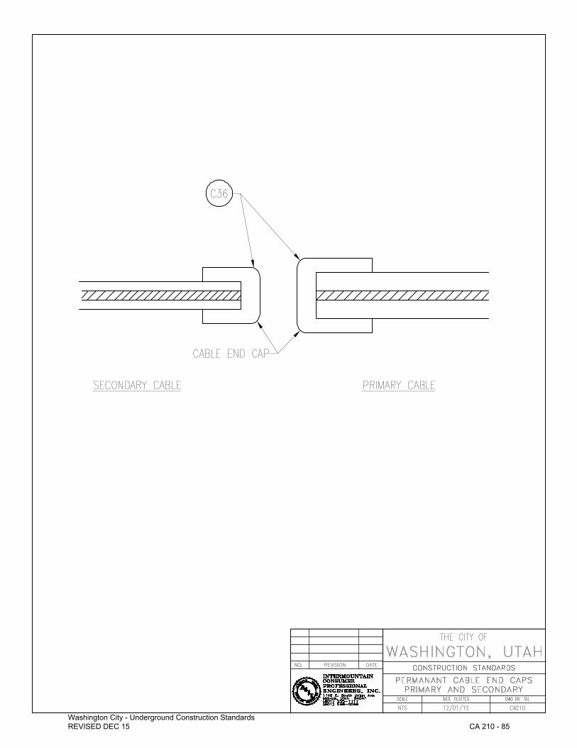
Washington City - Underground Construction Standards REVISED DEC 15
CA 210 - 85

DIRECT BURIED ONE CONDUIT Washington City – Underground Construction Standard
CO 105 ‐ 86REVISED DEC 15
DIRECT BURIED ONE CONDUIT
ITEM DESCRIPTION
C59 PVC SCH 40 CONDUIT
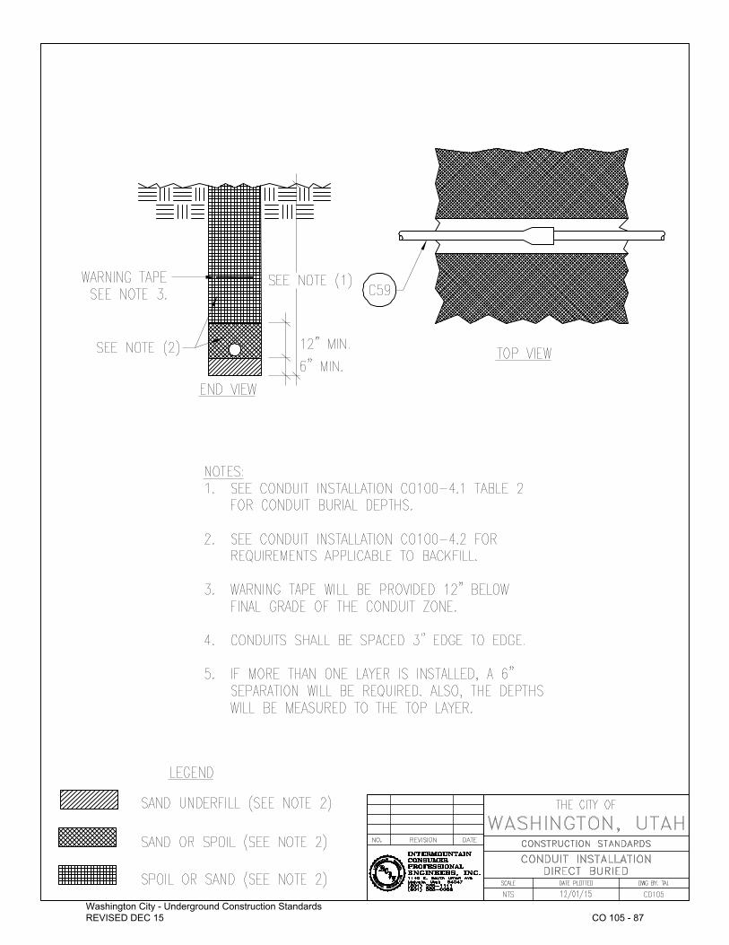
Washington City - Underground Construction Standards REVISED DEC 15
CO 105 - 87

UNDERGROUND INSTALLATIONS DIRECT BURIED FOUR CONDUITSWashington City – Underground Construction Standard
CO 120 ‐ 88REVISED DEC 15
UNDERGROUND INSTALLATIONS DIRECT BURIED FOUR CONDUITS
ITEM DESCRIPTION
C59 SCHEDULE 40 PVC CONDUIT
C61 CONDUIT SPACER – INTERMEDIATE
C62 CONDUIT SPACER ‐ BASE

Washington City - Underground Construction Standards REVISED DEC 15
CO 120 - 89

DIRECT BURIED 90 DEGREE STEEL CONDUIT ELBOWWashington City – Underground Construction Standard
CO 125 ‐ 90REVISED DEC 15
UNDERGROUND BURIED 90 DEGREE STEEL CONDUIT ELBOW
ITEM DESCRIPTION
C58 ADAPTOR PLASTIC TO STEEL
C63 90 DEGREE RIGID STEEL ELBOW
C66 CONDUIT BUSHING

Washington City - Underground Construction Standards REVISED DEC 15
CO 125 - 91
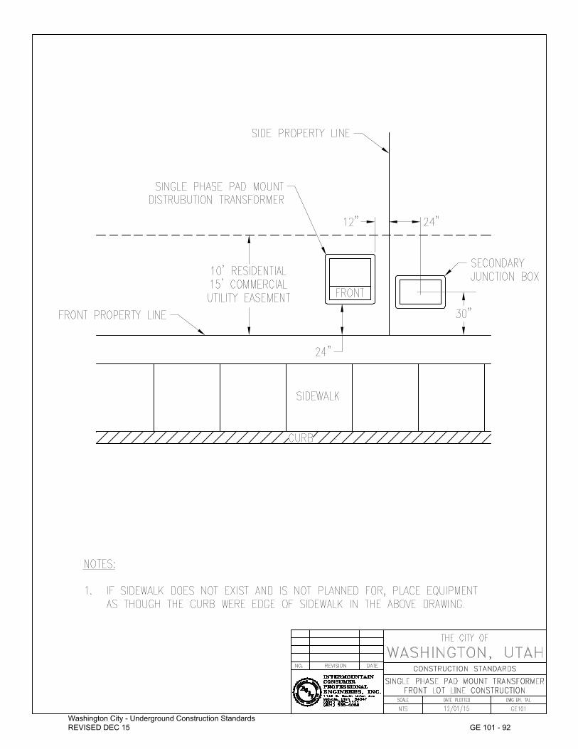
Washington City - Underground Construction Standards REVISED DEC 15
GE 101 - 92
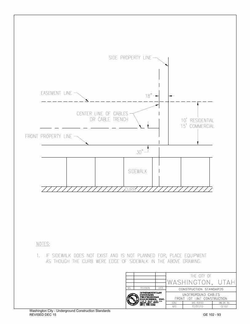
Washington City - Underground Construction Standards REVISED DEC 15
GE 102 - 93

Washington City - Underground Construction Standards REVISED DEC 15
GE 103 - 94
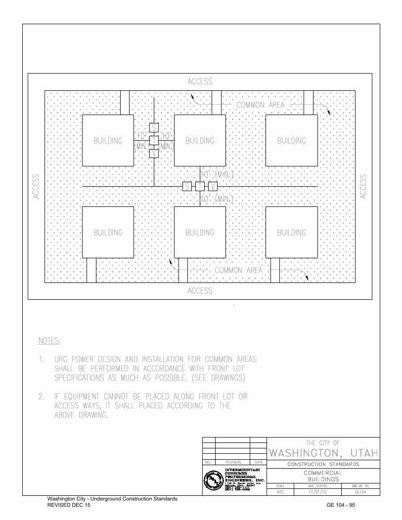
Washington City - Underground Construction Standards REVISED DEC 15
GE 104 - 95

Washington City - Underground Construction Standards REVISED DEC 15
GE 105 - 96

PADMOUNT SWITCHGEAR Washington City – Underground Construction Standard
PJ 505 ‐ 97REVISED DEC 15
PADMOUNT SWITCHGEAR
ITEM QTY DESCRIPTION
C34 12 TERMINAL CONNECTOR, COPPER CABLE TO FLAT BUSS
G7 10 #4/0 COPPER WIRE
G20 2 8' X 5/8" GROUND ROD
G21 2 GROUND ROD CONNECTOR
L20 4 PADLOCK
N41 28 1/2" STAINLESS STEEL HEX NUT
P10 1 GROUND SLEEVE (SEE PJ525)
P40 1 15 kV PADMOUNT SWITCHGEAR (CONFIGURATION AS REQUIRED)
S20 24 1/2" X 1" STAINLESS STEEL CAP SCREW
S21 4 1/2" X 2" STAINLESS STEEL CAP SCREW
T31 12 CABLE TERMINATOR
W42 28 1/2" STAINLESS STEEL WASHER SET

Washington City - Underground Construction Standards REVISED DEC 15
PJ 505 - 98
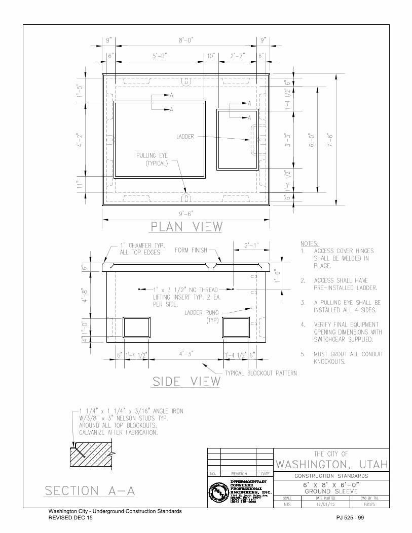
Washington City - Underground Construction Standards REVISED DEC 15
PJ 525 - 99

THREE PHASE FIBERGLASS PRIMARY VAULT ENCLOSUREWashington City – Underground Construction Standard
PV 105 ‐ 100REVISED DEC 15
THREE PHASE FIBERGLASS PRIMARY VAULT ENCLOSURE
ITEM QTY DESCRIPTION
E14 1 GROUND SLEEVE MOUNTED, PRIMARY ENCLOSURE WITH JUNCTION MOUNTING BAR AND GROUND BAR. (PDI Catalog Number CJP‐31‐50‐L2‐MG‐4025)
G6 10’ #2/0 AWG COPPER STRANDED BARE GROUND WIRE
G20 2 8' X 5/8" GROUND ROD
G21 2 GROUND ROD CONNECTOR
L20 1 PADLOCK
TA 3 200A LOADBREAK JUNCTION (SEE TA120, TA125, TA130, AND TA135)

Washington City - Underground Construction Standards REVISED DEC 15
PV 105 - 101

SINGLE PHASE FIBERGLASS PRIMARY VAULT ENCLOSUREWashington City – Underground Construction Standard
PV 110 ‐ 102REVISED DEC 15
SINGLE PHASE FIBERGLASS PRIMARY VAULT ENCLOSURE
ITEM QTY DESCRIPTION
E14 1 GROUND SLEEVE MOUNTED, PRIMARY ENCLOSURE WITH JUNCTION MOUNTING BAR AND GROUND BAR. (PDI Catalog Number CJP‐10‐49‐L2‐MG‐4026)
G6 10’ #2/0 AWG COPPER STRANDED BARE GROUND WIRE
G20 2 8' X 5/8" GROUND ROD
G21 2 GROUND ROD CONNECTOR
L20 1 PADLOCK
TA 1 200A LOADBREAK JUNCTION (SEE TA120, TA125, TA130, AND TA135)

Washington City - Underground Construction Standards REVISED DEC 15
PV 110 - 103

SECONDARY JUNCTION BOX Washington City – Underground Construction Standard
SJ 100 ‐ 104REVISED DEC 15
SECONDARY JUNCTION BOX
ITEM QTY DESCRIPTION
SJ1 1 SECONDARY JUNCTION BOX (CARSON CAT. #P1220‐27)
C1 AS REQ’D
SECONDARY CONDUCTOR CONNECTORS

Washington City - Underground Construction Standards REVISED DEC 15
SJ 100 - 105

LARGE SECONDARY JUNCTION BOX Washington City – Underground Construction Standard
SJ 105 ‐ 106REVISED DEC 15
LARGE SECONDARY JUNCTION BOX
ITEM QTY DESCRIPTION
SJ2 1 LARGE SECONDARY JUNCTION BOX (NORDIC CAT. #PSP‐151530‐MG)
C1 AS REQ’D
SECONDARY CONDUCTOR CONNECTORS

Washington City - Underground Construction Standards REVISED DEC 15
SJ 105 - 107

MOBILE HOME PARK METER PEDESTAL Washington City – Underground Construction Standard
SJ 110 ‐ 108REVISED DEC 15
MOBILE HOME PARK METER PEDESTAL
ITEM QTY DESCRIPTION
C30 2 COMPRESSION CONNECTOR
G7 10 #4 SOLID COPPER WIRE
G20 1 8’ x 5/8” GROUND ROD
G21 1 GROUND ROD CONNECTOR
L21 1 PEDESTAL EQUIPMENT LOCK
P29 1 MOBILE HOME PARK METER PEDESTAL

Washington City - Underground Construction Standards REVISED DEC 15
SJ 110 - 109
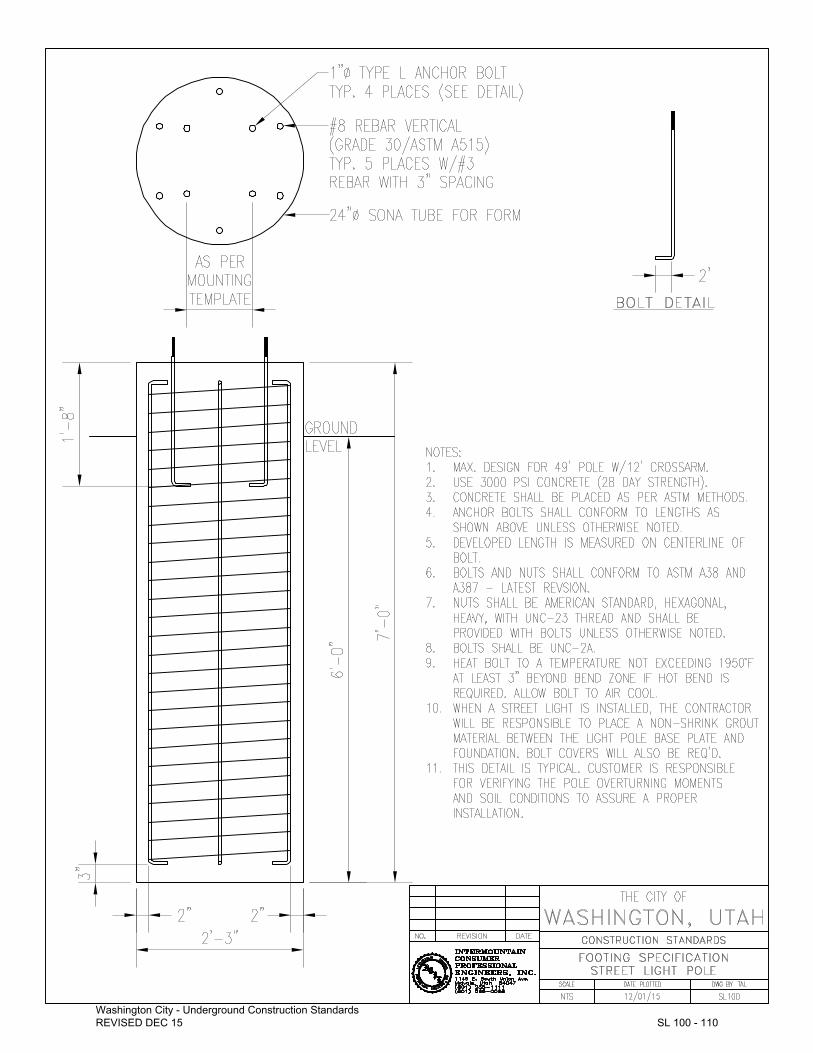
Washington City - Underground Construction Standards REVISED DEC 15
SL 100 - 110

SECONDARY CABLE SPLICE Washington City – Underground Construction Standard
SP 105 ‐ 111REVISED DEC 15
SECONDARY CABLE SPLICE
ITEM QTY DESCRIPTION
C31 1 END‐TO‐END COMPRESSION CONNECTOR
S30 1 HEAT SHRINKABLE SLEEVE

Washington City - Underground Construction Standards REVISED DEC 15
SP 105 - 112

200 AMP CONCENTRIC NEUTRAL PRIMARY CABLE SPLICEWashington City – Underground Construction Standard
SP 110 ‐ 113REVISED DEC 15
200 AMP CONCENTRIC NEUTRAL PRIMARY CABLE SPLICE
ITEM QTY DESCRIPTION
C30 4 COMPRESSION CONNECTOR
G6 2 #2 AWG COPPER STRANDED BARE GROUND WIRE
S31 1 IN‐LINE SPLICE, URD CABLE (ALL SPLICES MUST BE APPROVED BY THE CITY BEFORE INSTALLATION)
T30 1 INSULATING TAPE

Washington City - Underground Construction Standards REVISED DEC 15
SP 110 - 114

600 AMP CONCENTRIC NEUTRAL PRIMARY CABLE SPLICEWashington City – Underground Construction Standard
SP 115 ‐ 115REVISED DEC 15
600 AMP CONCENTRIC NEUTRAL PRIMARY CABLE SPLICE
ITEM QTY DESCRIPTION
C30 4 COMPRESSION CONNECTOR
G6 2 #2 AWG COPPER STRANDED BARE GROUND WIRE
S31 1 IN‐LINE SPLICE, URD CABLE (ALL SPLICES MUST BE APPROVED BY THE CITY BEFORE INSTALLATION)
*Terminators – Raychem or Equivalent1. 4/0 = #HVT‐152‐SJ 2. 500 = #HVT‐153‐SJ 3. 750 = #HVT‐153‐SJ

Washington City - Underground Construction Standards REVISED DEC 15
SP 115 - 116
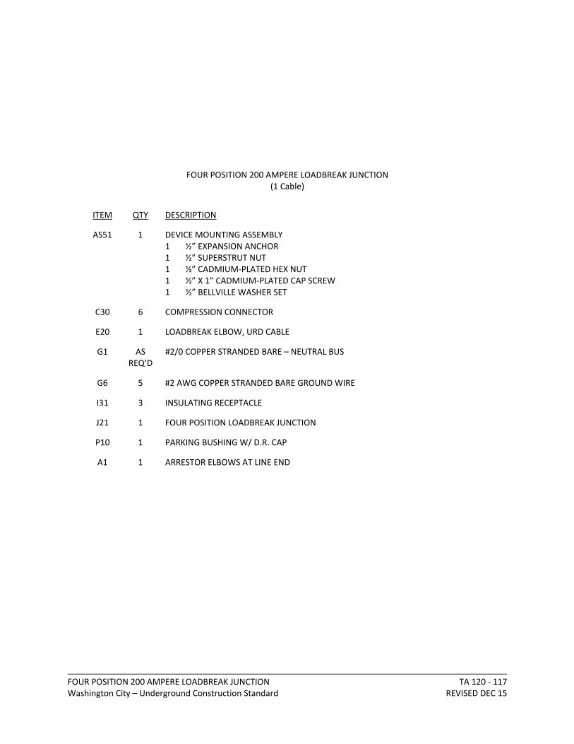
FOUR POSITION 200 AMPERE LOADBREAK JUNCTIONWashington City – Underground Construction Standard
TA 120 ‐ 117REVISED DEC 15
FOUR POSITION 200 AMPERE LOADBREAK JUNCTION (1 Cable)
ITEM QTY DESCRIPTION
AS51 1 DEVICE MOUNTING ASSEMBLY1 ½” EXPANSION ANCHOR 1 ½” SUPERSTRUT NUT 1 ½” CADMIUM‐PLATED HEX NUT 1 ½” X 1” CADMIUM‐PLATED CAP SCREW 1 ½” BELLVILLE WASHER SET
C30 6 COMPRESSION CONNECTOR
E20 1 LOADBREAK ELBOW, URD CABLE
G1 AS REQ’D
#2/0 COPPER STRANDED BARE – NEUTRAL BUS
G6 5 #2 AWG COPPER STRANDED BARE GROUND WIRE
I31 3 INSULATING RECEPTACLE
J21 1 FOUR POSITION LOADBREAK JUNCTION
P10 1 PARKING BUSHING W/ D.R. CAP
A1 1 ARRESTOR ELBOWS AT LINE END

Washington City - Underground Construction Standards REVISED DEC 15
TA 120 - 118

FOUR POSITION 200 AMPERE LOADBREAK JUNCTIONWashington City – Underground Construction Standard
TA 125 ‐ 119REVISED DEC 15
FOUR POSITION 200 AMPERE LOADBREAK JUNCTION (2 Cables)
ITEM QTY DESCRIPTION
AS51 1 DEVICE MOUNTING ASSEMBLY1 ½” EXPANSION ANCHOR 1 ½” SUPERSTRUT NUT 1 ½” CADMIUM‐PLATED HEX NUT 1 ½” X 1” CADMIUM‐PLATED CAP SCREW 1 ½” BELLVILLE WASHER SET
C30 8 COMPRESSION CONNECTOR
E20 2 LOADBREAK ELBOW, URD CABLE
G1 AS REQ’D
#2/0 COPPER STRANDED BARE – NEUTRAL BUS
G6 5 #2 AWG COPPER STRANDED BARE GROUND WIRE
I31 2 INSULATING RECEPTACLE
J21 1 FOUR POSITION LOADBREAK JUNCTION
P10 1 PARKING BUSHING WITH DR CAP
A1 1 ARRESTOR ELBOW AT LINE END (As required)

Washington City - Underground Construction Standards REVISED DEC 15
TA 125 - 120

FOUR POSITION 200 AMPERE LOADBREAK JUNCTIONWashington City – Underground Construction Standard
TA 130 ‐ 121REVISED DEC 15
FOUR POSITION 200 AMPERE LOADBREAK JUNCTION (3 Cables)
ITEM QTY DESCRIPTION
AS51 1 DEVICE MOUNTING ASSEMBLY1 ½” EXPANSION ANCHOR 1 ½” SUPERSTRUT NUT 1 ½” CADMIUM‐PLATED HEX NUT 1 ½” X 1” CADMIUM‐PLATED CAP SCREW 1 ½” BELLVILLE WASHER SET
C30 10 COMPRESSION CONNECTOR
E20 3 LOADBREAK ELBOW, URD CABLE
G1 AS REQ’D
#2/0 COPPER STRANDED BARE – NEUTRAL BUS
G6 5 #2 AWG COPPER STRANDED BARE GROUND WIRE
I31 1 INSULATING RECEPTACLE
J21 1 FOUR POSITION LOADBREAK JUNCTION
P10 1 PARKING BUSHING WITH DR CAP
A1 1 ARRESTOR ELBOW AT LINE END (As required)

Washington City - Underground Construction Standards REVISED DEC 15
TA 130 - 122
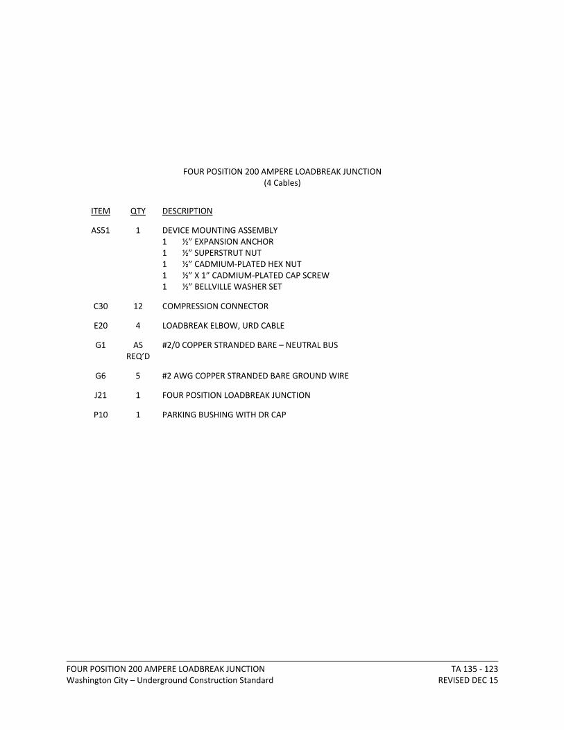
FOUR POSITION 200 AMPERE LOADBREAK JUNCTIONWashington City – Underground Construction Standard
TA 135 ‐ 123REVISED DEC 15
FOUR POSITION 200 AMPERE LOADBREAK JUNCTION (4 Cables)
ITEM QTY DESCRIPTION
AS51 1 DEVICE MOUNTING ASSEMBLY1 ½” EXPANSION ANCHOR 1 ½” SUPERSTRUT NUT 1 ½” CADMIUM‐PLATED HEX NUT 1 ½” X 1” CADMIUM‐PLATED CAP SCREW 1 ½” BELLVILLE WASHER SET
C30 12 COMPRESSION CONNECTOR
E20 4 LOADBREAK ELBOW, URD CABLE
G1 AS REQ’D
#2/0 COPPER STRANDED BARE – NEUTRAL BUS
G6 5 #2 AWG COPPER STRANDED BARE GROUND WIRE
J21 1 FOUR POSITION LOADBREAK JUNCTION
P10 1 PARKING BUSHING WITH DR CAP

Washington City - Underground Construction Standards REVISED DEC 15
TA 135 - 124

600 AMPERE DEADEND Washington City – Underground Construction Standard
TA 505 ‐ 125REVISED DEC 15
600 AMPERE DEADEND
ITEM QTY DESCRIPTION
AS50 1 600 AMPERE ELBOW ASSEMBLY1 CABLE ADAPTER 1 BASIC ELBOW 1 ELBOW CONTACT
P20 1 BASIC INSULATING PLUG
P21 1 DEADEND PLUG

Washington City - Underground Construction Standards REVISED DEC 15
TA 505 - 126
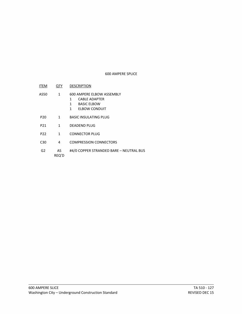
600 AMPERE SLICE Washington City – Underground Construction Standard
TA 510 ‐ 127REVISED DEC 15
600 AMPERE SPLICE
ITEM QTY DESCRIPTION
AS50 1 600 AMPERE ELBOW ASSEMBLY1 CABLE ADAPTER 1 BASIC ELBOW 1 ELBOW CONDUIT
P20 1 BASIC INSULATING PLUG
P21 1 DEADEND PLUG
P22 1 CONNECTOR PLUG
C30 4 COMPRESSION CONNECTORS
G2 AS REQ’D
#4/0 COPPER STRANDED BARE – NEUTRAL BUS

Washington City - Underground Construction Standards REVISED DEC 15
TA 510 - 128

600 AMPERE SLICE Washington City – Underground Construction Standard
TA 515 ‐ 129REVISED DEC 15
600 AMPERE THREE‐WAY SPLICE
ITEM QTY DESCRIPTION
AS50 1 600 AMPERE ELBOW ASSEMBLY1 CABLE ADAPTER 1 BASIC ELBOW 1 ELBOW CONDUIT
P20 1 BASIC INSULATING PLUG
P21 1 DEADEND PLUG
P22 1 CONNECTOR PLUG
C30 6 COMPRESSION CONNECTION
G2 AS REQ’D
#4/0 COPPER STRANDED BARE – NEUTRAL BUS
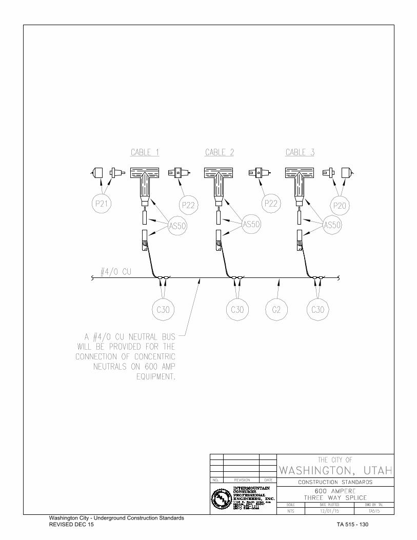
Washington City - Underground Construction Standards REVISED DEC 15
TA 515 - 130

Washington City - Underground Construction Standards REVISED DEC 15
US 103 - 131

Washington City - Underground Construction Standards REVISED DEC 15
US 110 - 132
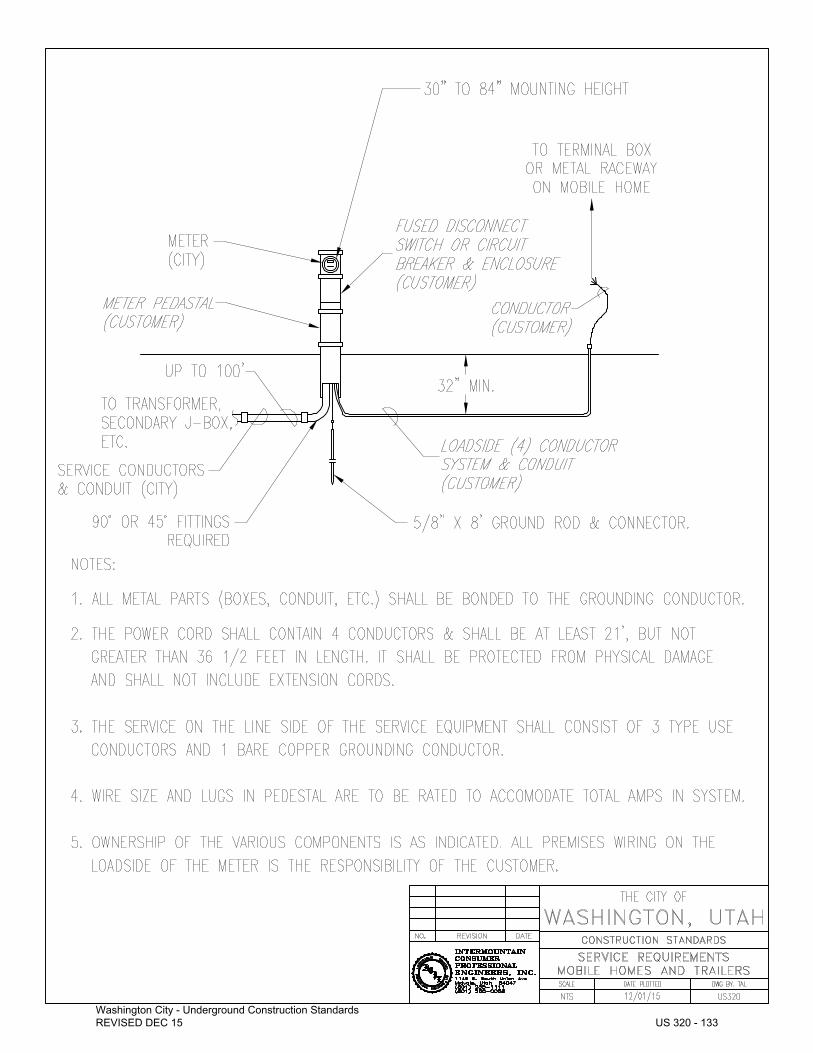
Washington City - Underground Construction Standards REVISED DEC 15
US 320 - 133
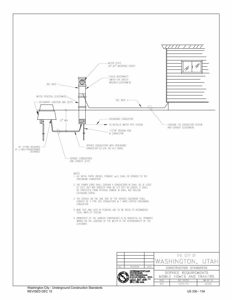
Washington City - Underground Construction Standards REVISED DEC 15
US 330 - 134

LOOP FEED SINGLE‐PHASE PADMOUNT DISTRIBUTION TRANSFORMERWashington City – Underground Construction Standard
UT 105 ‐ 135REVISED DEC 15
LOOP FEED SINGLE‐PHASE PADMOUNT DISTRIBUTION TRANSFORMER
ITEM QTY DESCRIPTION
C9 2 TRANSFORMER GROUND CONNECTOR
C30 2 COMPRESSION CONNECTION
E20 2 LOADBREAK ELBOW, 15 kV URD CABLE
G7 10 #4 SOLID COPPER WIRE
G20 1 8' X 5/8" GROUND ROD
G21 1 GROUND ROD CONNECTOR
I30 2 15 kV BUSHING INSERT
L20 1 PADLOCK
G22 1 SINGLE‐PHASE TRANSFORMER PAD (SEE UT190)
P23 1 STANDOFF PLUG
P30 1 SINGLE‐PHASE PADMOUNT DISTRIBUTION TRANSFORMER
3 SET SCREW TYPE BUSS CONNECTORS 500 MCM OR SMALLER(NOTE: WIRE OVER 500 MCM MAY BE BOLTED.)

Washington City - Underground Construction Standards REVISED DEC 15
UT 105 - 136

RADIAL FEED THREE‐PHASE PADMOUNT TRANSFORMERWashington City – Underground Construction Standard
UT 160 ‐ 137REVISED DEC 15
RADIAL FEED THREE‐PHASE PADMOUNT TRANSFORMER
ITEM QTY DESCRIPTION
C9 2 TRANSFORMER GROUND CONNECTOR
C30 6 COMPRESSION CONNECTION
E20 3 LOADBREAK ELBOW, 15 kV URD CABLE
G6 10 #2 AWG COPPER STRANDED BARE GROUND WIRE
G7 5 #4 SOLID COPPER WIRE
G20 1 8' x 5/8" GROUND ROD
G21 1 GROUND ROD CONNECTOR
I30 3 15 kV BUSHING INSERT
L20 1 PADLOCK
M10 1 MOUNTING PAD AS PER CITY SPECS (SEE UT185)
P31 1 THREE‐PHASE PADMOUNT DISTRIBUTION TRANSFORMER
3 SET SCREW TYPE BUSS CONNECTORS 500 MCM OR SMALLER(NOTE: WIRE OVER 500 MCM MAY BE BOLTED.)
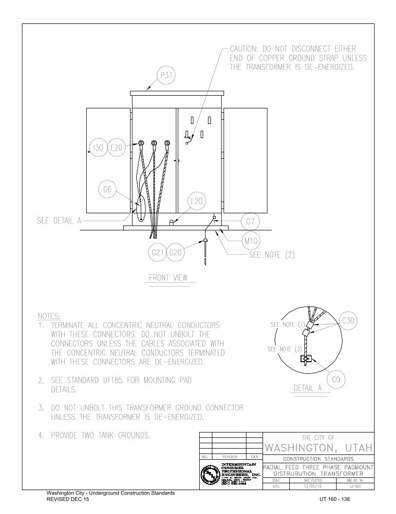
Washington City - Underground Construction Standards REVISED DEC 15
UT 160 - 138

LOOP FEED THREE‐PHASE PADMOUNT TRANSFORMERWashington City – Underground Construction Standard
UT 170 ‐ 139REVISED DEC 15
LOOP FEED THREE‐PHASE PADMOUNT TRANSFORMER
ITEM QTY DESCRIPTION
C9 2 TRANSFORMER GROUND CONNECTOR
C30 6 COMPRESSION CONNECTION
E20 6 LOADBREAK ELBOW, 15 kV URD CABLE
G6 10 #2 AWG COPPER STRANDED BARE GROUND WIRE
G7 5 #4 SOLID COPPER WIRE
G20 1 8' x 5/8" GROUND ROD
G21 1 GROUND ROD CONNECTOR
I30 6 15 kV BUSHING INSERT
L20 1 PADLOCK
M10 1 MOUNTING PAD AS PER CITY SPECS (SEE UT185)
P31 1 THREE‐PHASE PADMOUNT DISTRIBUTION TRANSFORMER
3 SET SCREW TYPE BUSS CONNECTORS 500 MCM OR SMALLER(NOTE: WIRE OVER 500 MCM MAY BE BOLTED.)
NOTE: If only a single set of H.V. cables are installed, provide three insulating caps and arrester elbows for the
unused H.V. cable positions.

Washington City - Underground Construction Standards REVISED DEC 15
UT 170 - 140
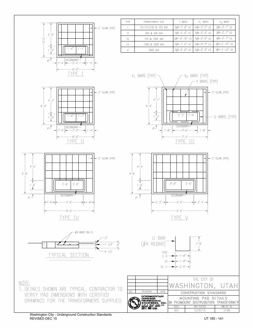
Washington City - Underground Construction Standards REVISED DEC 15
UT 185 - 141

Washington City - Underground Construction Standards REVISED DEC 15
UT 190 - 142