underground feasibility study - energizeeastsideeis.org · aerial route drawings ... perform an...
TRANSCRIPT

POWER ENGINEERS, INC.
STL 085-1244 (SR-02) 130155 (03/31/2014) MM
March, 2014
PUGET SOUND ENERGY
Eastside 230 kV Project Underground Feasibility Study
PROJECT NUMBER: 130155
PROJECT CONTACT: POWER ENGINEERS, INC.

POWER ENGINEERS, INC.
STL 085-1244 (SR-02) 130155 (03/31/2014) MM
Underground Report
PREPARED FOR: PSE
PREPARED BY: POWER ENGINEERS, INC.
REVISION HISTORY
DATE REVISED BY REVISION
8/20/12 POWER Engineers, Inc. 1st Draft Issued for Review
8/20/12 POWER Engineers, Inc. Final Report
3/2014 POWER Engineers, Inc. Updated Final Report

POWER ENGINEERS, INC.
STL 085-1244 (SR-02) 130155 (03/31/2014) MM PAGE i
TABLE OF CONTENTS
PREFACE ...................................................................................................................................................... 2 0.0 EXECUTIVE SUMMARY .................................................................................................................... 3 1.0 PROJECT DESCRIPTION .................................................................................................................... 5 2.0 UNDERGROUND CABLE SYSTEMS ................................................................................................... 5
2.1 Cross-Linked Polyethylene Cable Systems ................................................................................ 5 2.2 High-Pressure Fluid-Filled Cable Systems ............................................................................... 14 2.3 Reliability and Cable System Comparisons (XLPE vs. HPFF) ................................................ 19 2.4 Termination Stations / Termination Structures ......................................................................... 21 2.5 Additional Available Cable Systems ........................................................................................ 24
3.0 UNDERGROUND CONCEPTUAL DESIGN ......................................................................................... 25 3.1 Review of Existing 115 kV ROW (PSE Easement) .................................................................. 26 3.2 Review of Roadway Alternate .................................................................................................. 32 3.3 Review of Railroad Alternate ................................................................................................... 34 3.4 Review of Seattle City Light Tap Alternate .............................................................................. 36 3.5 XLPE Cable System Design ..................................................................................................... 38 3.6 HPFF Cable System Design ...................................................................................................... 39
4.0 CABLE DESIGN .............................................................................................................................. 41 4.1 Cross-Linked Polyethylene Ampacity Calculations ................................................................. 41 4.2 High-Pressure Fluid-Filled Ampacity Calculations .................................................................. 42 4.3 Summary of Ampacity Calculations ......................................................................................... 43 4.4 Conclusion of Ampacity Calculations ...................................................................................... 43 4.5 High-Pressure Fluid-Filled System Calculations ...................................................................... 44 4.6 Cross-linked Polyethylene System Calculations ....................................................................... 45
5.0 COST ESTIMATES & SCHEDULE .................................................................................................... 46 5.1 Cost Estimate Assumptions ...................................................................................................... 46 5.2 Summary of Cost Estimates ...................................................................................................... 47 5.3 Schedule .................................................................................................................................... 48 5.4 Summary of Schedule ............................................................................................................... 49
APPENDIX A .............................................................................................................................................. 50
Aerial Route Drawings ......................................................................................................................... 50
APPENDIX B .............................................................................................................................................. 51
Typical Detail Drawings ....................................................................................................................... 51

POWER ENGINEERS, INC.
STL 085-1244 (SR-02) 130155 (03/31/2014) MM PAGE 2
PREFACE In 2012, Puget Sound Energy (PSE) requested POWER Engineers, Inc. (POWER) review the constructability of underground transmission installation as part of the Eastside 230 kV Project. The scope of this work included conceptual designs for undergrounding all of the transmission from their Sammamish to Lakeside to Talbot Hill Substations. A review was performed for three alternatives:
1. Underground transmission on an existing PSE right of way 2. Underground transmission on an alternate alignment, primarily city street right of way 3. Underground transmission on an existing rail road right of way
In addition, PSE requested POWER review the constructability of an underground transmission link between existing Seattle City Light (SCL) overhead transmission lines and the Lakeside Substation. Since this study was completed, PSE has had further discussion with SCL regarding the availability of this corridor. SCL has stated that they have needs for this corridor for their own future development and SCL is not willing to make this corridor available to PSE. The transmission requirements for all alternatives would be a 230 kV double circuit line, with a rating capacity of 800 MVA continuous per circuit (1600 MVA total). This report documents the constructability review. Cost estimates have been updated to reflect 2014 pricing.

POWER ENGINEERS, INC.
STL 085-1244 (SR-02) 130155 (03/31/2014) MM PAGE 3
0.0 EXECUTIVE SUMMARY Puget Sound Energy (PSE) has requested a feasibility study for a 230 kilovolt (kV) underground transmission line connecting Sammamish Substation to Lakeside Substation and continuing to Talbot Hill Substation as part of its Eastside 230 kV Project. This study focuses on replacing and upgrading the existing 115 kV overhead lines with an underground 230 kV system from an engineering and constructability standpoint only. This study does not take into account:
1. Environmental, local, state, and federal permits and/or mitigation as required, 2. Acquisition of new right of way, easements, or properties, or 3. Local land use preferences among the identified route alternatives.
POWER Engineers, Inc. (POWER) was selected to study the conceptual cable system for this project. POWER identified a project study area for the underground portion of new 230 kV transmission lines and developed the criteria for an underground transmission line route evaluation. POWER evaluated the study area and identified three route alternatives:
1. One route option would utilize the existing 115 kV overhead lines easement, 2. A second option would be within existing street right of way, and 3. The last option would be along an existing railroad right of way.
PSE also requested that POWER investigate route options to “tap in” to 230 kV Seattle City Light (SCL) lines, just west of the Lakeside substation. Overhead transmission lines generally have larger power transfer capacity when compared to an equivalent insulated cable in an underground installation. Underground cable manufacturers are also limited in the size conductor they can produce to achieve a line rating with one cable per phase. POWER performed ampacity calculations for various underground line configurations to determine preliminary cable sizing requirements and concluded that two cables per phase would be needed to meet rating requirements for the new Eastside 230 kV lines. Two major types of cable systems were evaluated and compared for use on the proposed routes; cross-linked polyethylene (XLPE) and high-pressure fluid-filled (HPFF). Easement and construction requirements were discussed for each route option describing the size of easements required and the construction impacts. While all three route alternatives present different challenges such as difficult terrain, acquisition of additional easements/right of way, and existing utility conflicts, all routes are constructible. Cost estimates and project schedules were also created for all routes investigated with summary tables located in Section 5.

POWER ENGINEERS, INC.
STL 085-1244 (SR-02) 130155 (03/31/2014) MM PAGE 4
Based on this conceptual study, the results of the costs estimates are as follows:
Table 0-1 XLPE Total Cost Estimate – Two underground transmission lines, each with two cables per phase
Table 0-2 HPFF Total Cost Estimate – Two underground transmission lines, each with two cables per phase
SECTION LENGTH (miles) MATERIALSLABOR &
EQUIPMENTTOTAL
EXISTING OH EASEMENT 16.7 $238,520,375 $153,059,267 $391,579,641
STREET ROW 18.6 $294,934,505 $183,321,823 $478,256,327
RAILROAD 21.3 $331,474,512 $215,669,855 $547,144,366
SECTION LENGTH (miles) MATERIALSLABOR &
EQUIPMENTTOTAL
EXISTING OH EASEMENT 16.7 $298,821,059 $135,527,697 $434,348,756
STREET ROW 18.6 $359,434,051 $163,967,846 $523,401,897
RAILROAD 21.3 $398,566,198 $180,697,067 $579,263,265

POWER ENGINEERS, INC.
STL 085-1244 (SR-02) 130155 (03/31/2014) MM PAGE 5
1.0 PROJECT DESCRIPTION Puget Sound Energy (PSE) has proposed a rebuild of its Talbot Hill-Lakeside-Sammamish #1 and #2 overhead 115 kV transmission lines to 230 kV, and has identified the need to evaluate three underground route alternatives. PSE has requested that POWER Engineers, Inc. (POWER) perform an underground feasibility study to evaluate conceptual designs for each alternative. The two major types of 230 kV cable systems used for underground transmission application, high-pressure fluid-filled (HPFF), and cross-linked polyethylene (XLPE), are evaluated and compared as part of this study. In addition, a brief discussion of additional available cables systems are provided but are not considered practical alternatives for undergrounding the transmission lines. The pros and cons of each major type, HPFF and XLPE are considered for the installation options, and conceptual cable system designs developed for each as well. This report describes and summarizes:
The review of conceptual route alignments for new underground transmission lines, Considerations for each potential cable system, Preliminary cable system design options, and Cost estimates for each system considered,
Appendix A contains aerial route drawings for each underground transmission alternate. Appendix B contains typical detail drawings for each cable system (HPFF and XLPE) evaluated.
2.0 UNDERGROUND CABLE SYSTEMS The two most common types of underground transmission at 230 kV in the U.S. are cross-linked polyethylene and high-pressure fluid-filled cable systems.
2.1 Cross-Linked Polyethylene Cable Systems High voltage extruded dielectric cable installations in the U.S. are commonly in duct banks within roadways, one cable per duct, because direct burial and tunnel installations have not proven practical in city streets.
2.1.1 Cable The components of a typical dielectric cable are shown in Figure 2-1. The typical cable consists of a stranded copper or aluminum conductor, inner semi-conducting conductor shield, extruded solid dielectric insulation, outer semi-conducting shield, a metallic moisture barrier, and a protective jacket. The major insulation materials used for solid dielectric cables include ethylene propylene rubber (EPR) or cross-linked polyethylene (XLPE) thermosetting insulation compounds. For voltages over 69 kV, the preferred insulation in the U.S. for an extruded cable system is XLPE. This is due to the higher dielectric losses associated with EPR-insulated cables. For undergrounding the 230 kV Sammamish-Lakeside-Talbot lines with an extruded cable system, the insulation would be XLPE.

POWER ENGINEERS, INC.
STL 085-1244 (SR-02) 130155 (03/31/2014) MM PAGE 6
Materials used for semi-conducting extruded conductor and insulation shields are semi-conducting polyethylene (PE), XLPE, and EPR compounds. PE compounds are used with PE and XLPE insulation, XLPE compounds with XLPE insulation, and EPR compounds with EPR insulation. Cable jackets are typically extruded PE, and can be high, medium, low, or linear low–density polyethylene.
Figure 2-1: Typical XLPE Cable
The manufacturing process for extruded cables is of critical importance in ensuring a reliable end product. Triple extrusion is the preferred and recommended technique. Most transmission cable manufacturers use this “true triple head” extrusion technique today. Microscopic voids and contaminants can lead to cable failures. As such, quality control during manufacture of extruded dielectric cables is critical to minimize moisture contamination, voids, contaminants and protrusions. Manufacturers minimize insulation contamination by using super clean insulation compounds, transporting and storing the compounds in sealed facilities, and screening out contaminants at the extruder head. 2.1.2 Cable Accessories The fundamental cable accessories for extruded dielectric cables include splices, terminations, clamps, and sheath bonding materials. Pre-fabricated or pre-molded splices are commonly used to join extruded dielectric cables. Cable preparation for each of these types of splices is generally the same. Insulation and shields are removed from the conductor; and the insulation is penciled near the conductor. The conductor ends are then joined by a compression splice or, if aluminum, are welded. An advantage of using these types of splices is that all parts can be factory tested prior to field installation. Figure 2-2 shows typical 230 kV pre-molded splices racked within a splicing vault.
1 - CONDUCTORMaterial: copper
2 - INNER SEMI CONDUCTIVE SHIELD
3 - EXTRUDED SOLID DIELE TRIC INSULATION Material: cross - linked polyethylene
4 - OUTER SEMI-CONDUCTIVE SHIELD
5 - SEMI CONDUCTIVE SWELLING/BEDDING TAPES
6 - CONCENTRIC COPPER WIR E METALLIC SHIELD
7 – OPTICAL FIBERS
8 - SEMI CONDUCTIVE SWELLING/BEDDING TAPES
9 - MOISTURE BARRIER /S HEATH Material: copper, aluminum, lead, orstainless steel
10- PROTECTIVE JACKET

POWER ENGINEERS, INC.
STL 085-1244 (SR-02) 130155 (03/31/2014) MM PAGE 7
Figure 2-2 Typical 230 kV Pre-Molded XLPE Splices
Terminations are necessary for extruded dielectric cable to allow transitions to overhead lines or above ground equipment. Termination bodies are typically made of porcelain or polymer and include skirts or sheds, which provide additional surface area to minimize the probability of external flashovers due to contamination. Figure 2-3 shows typical 230 kV XLPE terminations.

POWER ENGINEERS, INC.
STL 085-1244 (SR-02) 130155 (03/31/2014) MM PAGE 8
Figure 2-3 Typical 230 kV XLPE Terminations
Another important component of a high voltage extruded cable system is the grounding/bonding of the cable shield. An underground distribution cable system would typically have the cable shield grounded at each splice and termination. The losses due to heat caused by circulating currents on the cable shield will result in the de-rating of the cable. One way to maximize the ampacity of an underground cable is to eliminate the circulating currents. This is accomplished with underground transmission cables by using special bonding methods such as single-point and cross-bonding. These methods reduce or even eliminate the amount of current that would flow on the cable shield resulting in no or very limited additional heating and ultimately a higher ampacity. 2.1.3 Civil Installation Open Cut Excavation Method The most basic and economical method for constructing an underground duct bank is by open-cut trenching, however, trenchless methods may also be necessary for crossing major obstructions. Typical construction results in the use of mechanical excavation to remove the
POWER ENGINEERS, INC.
STL 085-1244 (SR-02) 130155 (03/31/2014) MM PAGE 9
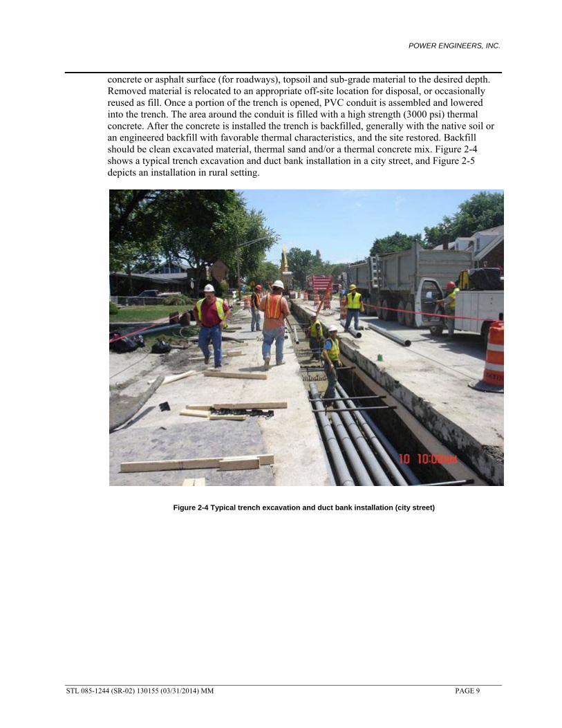
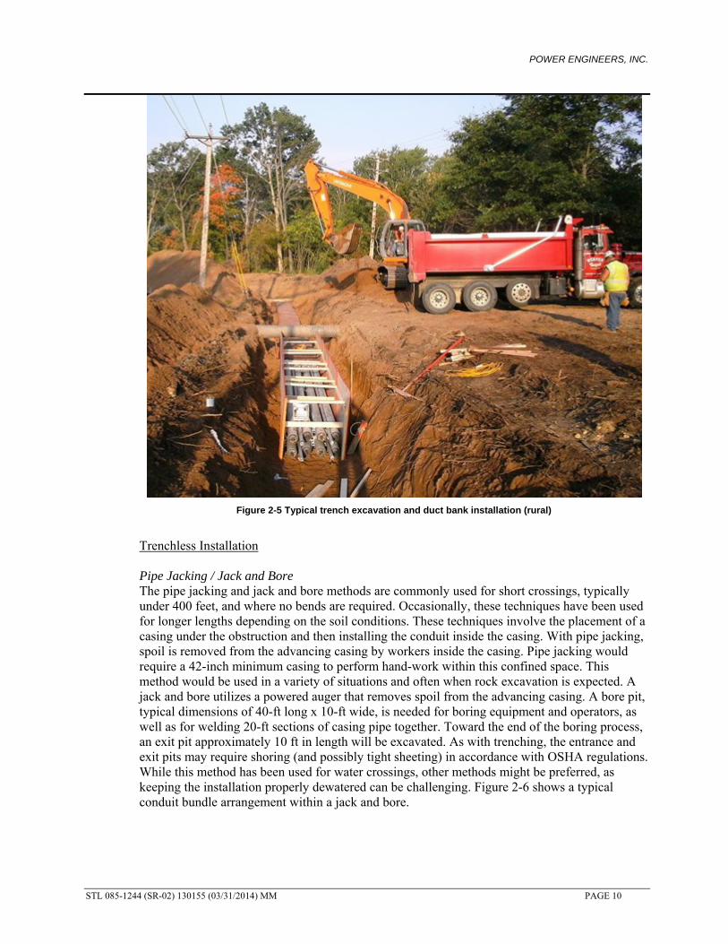
concrete or asphalt surface (for roadways), topsoil and sub-grade material to the desired depth. Removed material is relocated to an appropriate off-site location for disposal, or occasionally reused as fill. Once a portion of the trench is opened, PVC conduit is assembled and lowered into the trench. The area around the conduit is filled with a high strength (3000 psi) thermal concrete. After the concrete is installed the trench is backfilled, generally with the native soil or an engineered backfill with favorable thermal characteristics, and the site restored. Backfill should be clean excavated material, thermal sand and/or a thermal concrete mix. Figure 2-4 shows a typical trench excavation and duct bank installation in a city street, and Figure 2-5 depicts an installation in rural setting.
Figure 2-4 Typical trench excavation and duct bank installation (city street)
POWER ENGINEERS, INC.
STL 085-1244 (SR-02) 130155 (03/31/2014) MM PAGE 10
Figure 2-5 Typical trench excavation and duct bank installation (rural)
Trenchless Installation Pipe Jacking / Jack and Bore The pipe jacking and jack and bore methods are commonly used for short crossings, typically under 400 feet, and where no bends are required. Occasionally, these techniques have been used for longer lengths depending on the soil conditions. These techniques involve the placement of a casing under the obstruction and then installing the conduit inside the casing. With pipe jacking, spoil is removed from the advancing casing by workers inside the casing. Pipe jacking would require a 42-inch minimum casing to perform hand-work within this confined space. This method would be used in a variety of situations and often when rock excavation is expected. A jack and bore utilizes a powered auger that removes spoil from the advancing casing. A bore pit, typical dimensions of 40-ft long x 10-ft wide, is needed for boring equipment and operators, as well as for welding 20-ft sections of casing pipe together. Toward the end of the boring process, an exit pit approximately 10 ft in length will be excavated. As with trenching, the entrance and exit pits may require shoring (and possibly tight sheeting) in accordance with OSHA regulations. While this method has been used for water crossings, other methods might be preferred, as keeping the installation properly dewatered can be challenging. Figure 2-6 shows a typical conduit bundle arrangement within a jack and bore.

POWER ENGINEERS, INC.
STL 085-1244 (SR-02) 130155 (03/31/2014) MM PAGE 11
Figure 2-6 Typical Jack and Bore Conduit and Casing Arrangement
Horizontal Directional Drilling (HDD) The HDD method is commonly used for longer crossings and where bends may be needed. A HDD installation for an XLPE cable system consists of installing a casing with conduits inside or just installing the conduits in a bundle by themselves. The HDD method consists of a three step process. First, a small diameter pilot hole is drilled from entry to exit, followed by a reamer that is pulled back to enlarge the pilot hole. Finally, the product pipe is pulled into the enlarged hole. Horizontal boring operations have become quite popular with utilities since it eliminates the need to excavate large bore pits and the work can be performed from the surface. While this method does not require any significant pit excavation, it does require a generous staging area at the entry point and exit points of the drill. A typical entry point site requires a dedicated space of about 100 ft by 150 ft with an exit area of 100 ft by 100 ft. A typical set up used at the HDD entry point is shown below in Figure 2-7 below.
Figure 2-7 Typical HDD Setup

POWER ENGINEERS, INC.
STL 085-1244 (SR-02) 130155 (03/31/2014) MM PAGE 12
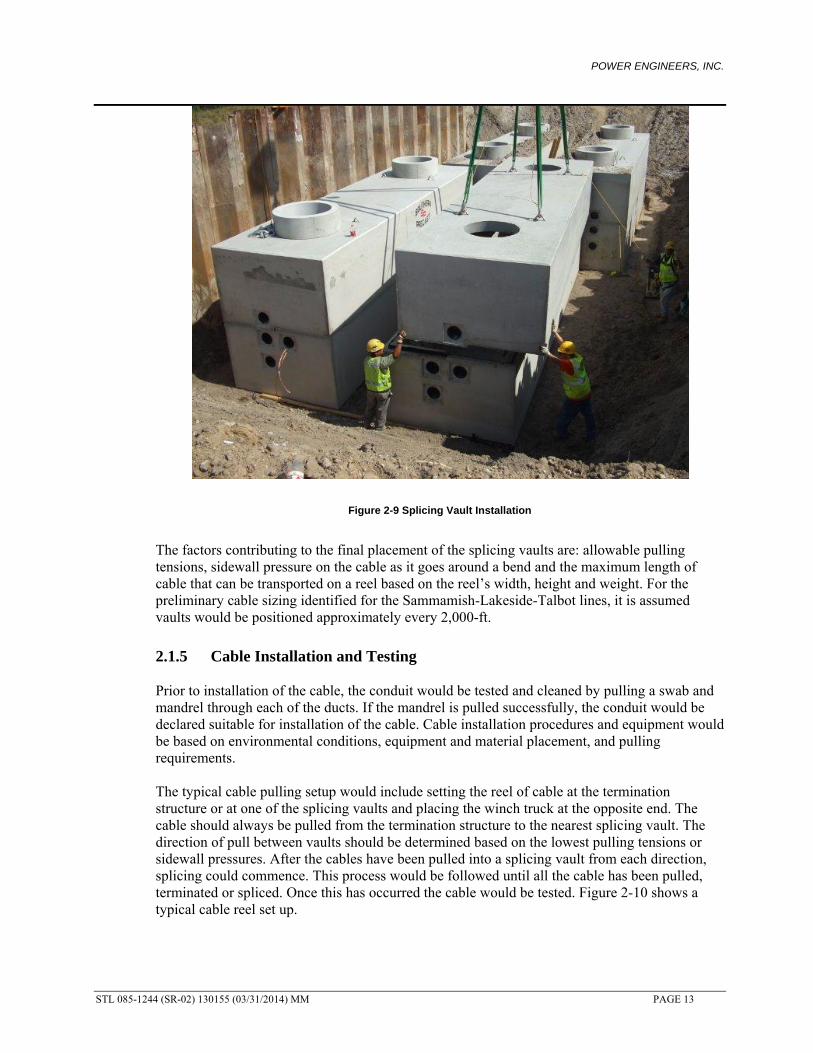
2.1.4 Splicing Vault Design and Installation Access vaults are needed periodically along an underground route to facilitate cable installation, for maintenance, as well as access for future repairs. Reinforced concrete vaults are typically spaced every 1,500 to 2,500 feet along the route. The splicing vault size and layout is determined by the space required for cable pulling, splicing, and supporting the cable in the vault. The anticipated size of each 230 kV XLPE splicing vault would have inside dimensions of about 7 ft wide by 26 ft long with enough headroom to allow workers to install the cable, as illustrated in Figure 2-8. A vault may be needed for each set of cables for this project, to allow PSE to perform maintenance or repair on one set of cables while keeping the other energized. Figure 2-9 shows an underground transmission splicing vault installation for a 230 kV XLPE project. For this particular installation there were four 3-phase cable sets of and four vaults total.
Figure 2-8 XLPE Vault Schematic
POWER ENGINEERS, INC.
STL 085-1244 (SR-02) 130155 (03/31/2014) MM PAGE 13
Figure 2-9 Splicing Vault Installation
The factors contributing to the final placement of the splicing vaults are: allowable pulling tensions, sidewall pressure on the cable as it goes around a bend and the maximum length of cable that can be transported on a reel based on the reel’s width, height and weight. For the preliminary cable sizing identified for the Sammamish-Lakeside-Talbot lines, it is assumed vaults would be positioned approximately every 2,000-ft.
2.1.5 Cable Installation and Testing Prior to installation of the cable, the conduit would be tested and cleaned by pulling a swab and mandrel through each of the ducts. If the mandrel is pulled successfully, the conduit would be declared suitable for installation of the cable. Cable installation procedures and equipment would be based on environmental conditions, equipment and material placement, and pulling requirements. The typical cable pulling setup would include setting the reel of cable at the termination structure or at one of the splicing vaults and placing the winch truck at the opposite end. The cable should always be pulled from the termination structure to the nearest splicing vault. The direction of pull between vaults should be determined based on the lowest pulling tensions or sidewall pressures. After the cables have been pulled into a splicing vault from each direction, splicing could commence. This process would be followed until all the cable has been pulled, terminated or spliced. Once this has occurred the cable would be tested. Figure 2-10 shows a typical cable reel set up.

POWER ENGINEERS, INC.
STL 085-1244 (SR-02) 130155 (03/31/2014) MM PAGE 14
Figure 2-10 Typical Cable Pulling Set up
2.2 High-Pressure Fluid-Filled Cable Systems
2.2.1 Cable A typical high-pressure fluid-filled (HPFF) cable is composed of a conductor, conductor shield (carbon black or metalized paper tapes), insulation (Kraft paper or paper/polypropylene laminate impregnated ‘LPP’ with dielectric fluid), insulation shield (carbon black or metalized paper tapes), a moisture barrier (non-magnetic tapes and metalized mylar tapes), and skid wires placed in a steel pipe filled with dielectric fluid or gas. The purpose of the dielectric fluid or gas is to keep moisture and contaminants out of the pipe and away from the cable. The moisture barrier prevents moisture and other contamination and loss of impregnating fluid prior to installation. The skid wires prevent damage to the cable during pulling. Three HPFF cables are pulled into a carbon steel pipe to constitute a cable system. The pipe is coated on the inside with an epoxy coating to prevent oxidation prior to pipe filling and to reduce pulling friction and tension. The pipe exterior is typically coated with polyethylene or epoxy to protect the pipe from environmental corrosion and to isolate the pipe from “ground” to allow use of a cathodic protection system. Figure 2-11 shows a typical cable and cable pipe cross-section.

POWER ENGINEERS, INC.
STL 085-1244 (SR-02) 130155 (03/31/2014) MM PAGE 15
Figure 2-11 Typical Cable and Cable Pipe Cross-Section
The manufacturing process is as follows: a conductor core is covered by helically wound with layers of metalized or carbon black paper tape for the conductor; high quality Kraft paper or paper/polypropylene laminate is then helically wound around the conductor in multiple layers for the insulation; additional layers of metalized or carbon black paper tape helically wound around the insulation to form the insulation shield; the insulated cable is dried and then impregnated with fluid in large pressurized tanks. Utilities have been increasing use of LPP insulation for voltages 115 kV and above because it has lower losses when compared to conventional Kraft paper. For this reason, the 230 kV Sammamish-Lakeside-Talbot lines would use LPP insulation for an HPFF configuration to meet the rating requirements. 2.2.2 Cable Accessories Splicing of HPFF cables begins with removal of the insulation and shields from the conductor, the insulation is tapered down to the conductor and the conductor ends are then joined. Insulation paper tape is wound around the spliced conductor, filling the tapered area of the insulation. Metalized tapes or carbon black tapes are used to re-establish the conductor and insulation shields. Hand applied tapes are used, as the three cables are very close together. Figure 2-12 shows a typical HPFF joint.

POWER ENGINEERS, INC.
STL 085-1244 (SR-02) 130155 (03/31/2014) MM PAGE 16
Figure 2-12 Typical HPFF Joint in a Vault
Terminations are made by first separating the three cables using a trifurcator. Each phase termination is then made in fluid-filled terminators. A typical HPFF cable termination in a substation is shown in Figure 2-13.
Figure 2-13 Typical HPFF Terminations in a Substation

POWER ENGINEERS, INC.
STL 085-1244 (SR-02) 130155 (03/31/2014) MM PAGE 17
Once the cable system has been installed, the pipe is filled with a synthetic dielectric fluid and is pressurized to a nominal 200 psi pressure. A special pressurization system is needed to monitor and maintain the nominal 200 psi pressure. Figure 2-14 shows a typical HPFF cable system arrangement with a fluid pressurization system.
Figure 2-14 Typical HPFF Cable System
A pressurization system for an HPFF cable system consists of three components: a pressurizing console, storage tank and a nitrogen supply. The pressurizing console consists of pressurizing pumps, valves and monitoring equipment. A nominal 200 psi must be maintained in the cable pipe at all times. As the temperature varies during normal operation, the pressure within the pipe would also vary. The system is designed to relieve the pressure as the temperature increases and maintain the pressure as the temperature decreases. A storage tank is provided to accept the extra fluid as the temperature of the cable system increases and provide fluid as the temperature of the cable system decreases or if a leak has occurred. The nitrogen supply maintains a pressure inside the storage tank and prevents any moisture from entering the system. The monitoring equipment controls the operation of the system and communicates the system status to the utility. The size of the pressurization plant would vary depending on the size of the storage tank. A typical size would be 10 feet wide by 50 feet long. Figure 2-15 shows a typical pressurization plant enclosure.
Figure 2-15 Typical Pressurization Plant

POWER ENGINEERS, INC.
STL 085-1244 (SR-02) 130155 (03/31/2014) MM PAGE 18
The number and location of pressurization plants depend on the length of the cable, elevation changes and other factors affecting fluid pressure in the pipe. 2.2.3 Civil Installation Open Cut Excavation Method As with an XLPE duct bank system, open cut trenching would generally be used for a HPFF cable system. Trenchless methods would also be used for crossing of major obstructions. Once the trench is excavated, the steel pipe would be welded together and installed in the trench. The area around the pipe would be filled with thermal sand or a fluidized thermal backfill to provide a good quality thermal environment around the pipe to facilitate heat transfer to earth and meet ampacity requirements. After the pipe encasement is installed, the trench would be backfilled and the site restored. Backfill materials could be clean excavated material, thermal sand and/or a thermal concrete mix. Trenchless Installation Trenchless techniques used to jack and bore or HDD would be similar to XLPE. However, since all three cable phases for an HPFF cable system are contained within a single steel pipe, the magnitude of trenchless installations are less than the equivalent XLPE cable system because a large bore diameter and bundle of conduits (with or without casing) to accommodate the cables are not required. 2.2.4 Vault Design and Installation Like the XLPE cable system, access vaults are needed periodically along an underground route to facilitate cable installation, for maintenance requirements and access for future repairs. Vault would be typically spaced every 2,500 to 3,500 feet along the route. The size of each vault would be about 8 ft wide by 20 ft long, as illustrated in Figure 2-16. Unlike the XLPE cable system, multiple cable pipes could be brought into a single vault for cable installation. For the preliminary cable sizing identified for the Sammamish-Lakeside-Talbot lines, it is assumed vaults would be positioned approximately every 2,500-ft.

POWER ENGINEERS, INC.
STL 085-1244 (SR-02) 130155 (03/31/2014) MM PAGE 19
Figure 2-16 HPFF Vault Schematic
2.2.5 Cable Installation and Testing As with the XLPE cable system, once the cable pipe and vaults have been installed, the cable could be installed. Prior to installation of the cable, the cable pipe would be pressure tested, evacuated tested and cleaned by pulling a mandrel and swab through the cable pipe. If all these tests are successfully completed, the cable pipe would be declared suitable for installation of the cable. Cable installation procedures and equipment would be based on environmental conditions, equipment and material placement and pulling requirements. While a single cable would be pulled in at one time for XLPE cable systems, all three cables are required to be pulled in simultaneously for an HPFF cable system. The setup would be similar except three reels of cables would be set up at one time.
2.3 Reliability and Cable System Comparisons (XLPE vs. HPFF) In general, underground transmission cable systems are very reliable. However, the main reliability issue with underground cables compared to overhead transmission is the length of the outage in the event of a cable failure. With overhead transmission, the line can generally be placed back into service in a relatively short amount of time, typically less than a day, thus increasing the line’s availability for transmitting load.

POWER ENGINEERS, INC.
STL 085-1244 (SR-02) 130155 (03/31/2014) MM PAGE 20
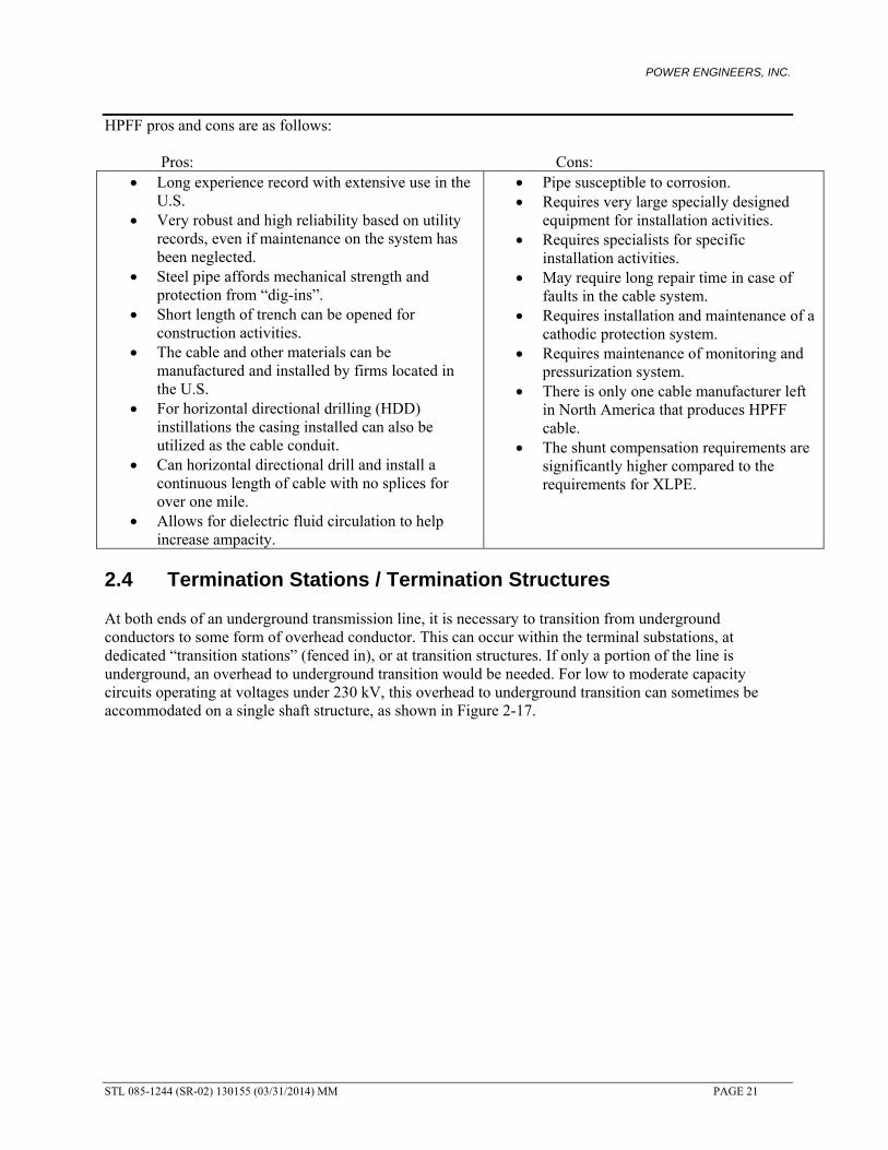
Outages on underground transmission cables are primarily caused by dig-ins (i.e., cable damage and fault due to excavation in the vicinity of the underground line). When there is a fault on an underground line, the line may be out of services for a significant amount of time, more than two weeks and up to six months, depending on the type of failure and how quickly it can be located and repaired. The main reason for very long repair times is if new cable and accessories would need to be manufactured, and the time it would take to get such necessary material and qualified personnel to perform the repair work. Because of these longer outage times an underground cable system has a lower circuit availability compared to an overhead line. HPFF cables have a very good track record and have historically proven to be a robust system with extremely high reliability at all available transmission voltage classes up to 345 kV. However, due to the uniqueness of the fluid pressurized system, very specialized personal are required to install the pipe, cable, accessories, and fluid to ensure successful operation and this high reliability. Additionally, while XLPE cables themselves have a low intrinsic failure rate because of stringent factory quality control and testing, splices and terminations are susceptible to failure because of their field assembly. Most utilities in the U.S. rely on the cable system manufacturer to provide skilled splicers and special tools to perform repairs of failures on XLPE transmission cables. XLPE cable systems have their individual pros and cons for consideration and are detailed below. Pros: Cons:
The cable system design, operation, and maintenance is less complex than systems with pressurized dielectric fluid.
Historically, high reliability reported and documented for systems of modern design at voltages 230 kV and below in the U.S., Japan and European countries.
Higher normal operating and short circuit temperature ratings as compared to HPFF systems
Installation environmental condition requirements for splicing and terminating less stringent.
Lower dielectric loses. Shorter time required for repair. Concrete encased duct bank systems provide
mechanical protection from dig-ins and allow for shortened lengths of trench to be opened during construction installation activities.
The charging current or reactive volt-amperes (VARS) generated by the cable are significantly less than HPFF insulation.
Susceptible to damage from dig-ins if direct buried, more so than HPFF pipe-type cable systems.
Potential for induced sheath voltages and losses.
Trench for installation of each cable length (direct buried) must be left open for the entire length during cable installation or required to leave cable reel exposed.
Duct bank / conduit installation may reduce thermal performance and increase cost.
It requires extremely strict manufacturing and process quality control because XLPE insulation not as forgiving (HPFF impregnated paper insulation is more tolerant of manufacturing defects and variances).
The high thermal expansion coefficient of the insulation presents special design problems for the metallic sheath and accessories.
Installation on steep slopes is a problem because the cables tend to ratchet downhill in the conduits.
POWER ENGINEERS, INC.
STL 085-1244 (SR-02) 130155 (03/31/2014) MM PAGE 21
HPFF pros and cons are as follows: Pros: Cons:
Long experience record with extensive use in the U.S.
Very robust and high reliability based on utility records, even if maintenance on the system has been neglected.
Steel pipe affords mechanical strength and protection from “dig-ins”.
Short length of trench can be opened for construction activities.
The cable and other materials can be manufactured and installed by firms located in the U.S.
For horizontal directional drilling (HDD) instillations the casing installed can also be utilized as the cable conduit.
Can horizontal directional drill and install a continuous length of cable with no splices for over one mile.
Allows for dielectric fluid circulation to help increase ampacity.
Pipe susceptible to corrosion. Requires very large specially designed
equipment for installation activities. Requires specialists for specific
installation activities. May require long repair time in case of
faults in the cable system. Requires installation and maintenance of a
cathodic protection system. Requires maintenance of monitoring and
pressurization system. There is only one cable manufacturer left
in North America that produces HPFF cable.
The shunt compensation requirements are significantly higher compared to the requirements for XLPE.
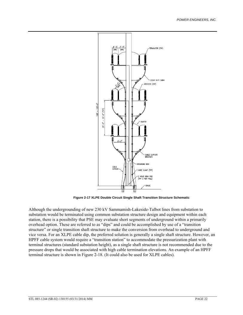
2.4 Termination Stations / Termination Structures At both ends of an underground transmission line, it is necessary to transition from underground conductors to some form of overhead conductor. This can occur within the terminal substations, at dedicated “transition stations” (fenced in), or at transition structures. If only a portion of the line is underground, an overhead to underground transition would be needed. For low to moderate capacity circuits operating at voltages under 230 kV, this overhead to underground transition can sometimes be accommodated on a single shaft structure, as shown in Figure 2-17.
POWER ENGINEERS, INC.
STL 085-1244 (SR-02) 130155 (03/31/2014) MM PAGE 22
Figure 2-17 XLPE Double Circuit Single Shaft Transition Structure Schematic
Although the undergrounding of new 230 kV Sammamish-Lakeside-Talbot lines from substation to substation would be terminated using common substation structure design and equipment within each station, there is a possibility that PSE may evaluate short segments of underground within a primarily overhead option. These are referred to as “dips” and could be accomplished by use of a “transition structure” or single transition shaft structure to make the conversion from overhead to underground and vice versa. For an XLPE cable dip, the preferred solution is generally a single shaft structure. However, an HPFF cable system would require a “transition station” to accommodate the pressurization plant with terminal structures (standard substation height), as a single shaft structure is not recommended due to the pressure drops that would be associated with high cable termination elevations. An example of an HPFF terminal structure is shown in Figure 2-18. (It could also be used for XLPE cables).

POWER ENGINEERS, INC.
STL 085-1244 (SR-02) 130155 (03/31/2014) MM PAGE 23
Figure 2-18 XLPE or HPFF Low Profile Transition Structure Schematic
When planning for an underground to overhead transmission line transition, be it a single transition shaft structure or a more complex “transition station”, several issues relating to the siting of the structure or station that would need to be considered are: environmental and permitting, community, physical site, and economic considerations.
2.4.1 Reactive Compensation The electrical capacitance per unit length of the underground transmission line is significantly higher than the capacitance for overhead transmission line because the dielectric constant of the insulation is several times higher than that of air and the ground potential for high voltage cables (the cable shield) is much closer than for overhead lines (the surface of the ground). For extra high voltage cable systems, the high capacitance of underground cables per unit of length results in relatively high charging current requirements. The reactive mega volt-amperes associated with the cable charging current must either be absorbed by the power system or shunt reactors may be required at one or more locations along the cable circuits. The reactors limit the voltage rise during light-load conditions, especially where the local power system is relatively weak (high system impedances) at the cable location. The shunt charging of the conceptual cable system designs are provided based on the cable sizing ampacity calculations in Section 5.0. If reactive compensation is needed, PSE would probably install shunt reactors at the ends of the transmission lines, with circuit breakers to disconnect the reactors during high load periods or for maintenance purposes. The capacitance also has a detrimental effect on the utility system for transient overvoltages, circuit breaker capacity, surge arrester duty, etc. If reactive compensation is required for the underground transmission lines, a “transition station” or additional substation room would be required for the equipment.
POWER ENGINEERS, INC.
STL 085-1244 (SR-02) 130155 (03/31/2014) MM PAGE 24
2.5 Additional Available Cable Systems There are additional available cable systems that could be used for the installation of new 230 kV underground transmission, however they are not practical for this project and have not been considered for undergrounding the Sammamish-Lakeside-Talbot lines. A brief discussion of each cable technology is as follows.
2.5.1 Self-Contained Fluid-Filled Self-contained fluid filled (SCFF) cable systems are very similar to HPFF systems. The cable is typically constructed around a hollow tube, used for fluid circulation, and uses the same Kraft paper or LPP insulation materials. Because the fluid system is “self-contained” the volume of fluid required is significantly less, however, the same distribution of pumping plants would be required. While SCFF cable systems have the longest running history at high voltage levels, their use is typically restrained to long submarine cable installations. (PSE has existing SCFF submarine cables in-service). Although, this technology has been implemented on inland applications with high reliability 230 kV, it is almost never used for land installations today; unless the installation is already related to an existing SCFF system. 2.5.2 Gas Insulated Transmission Line Gas insulated line (GIL) technology at the 230 kV voltage level has been implemented primarily within substations and not for longer transmission lines. GIL has been incorporated into substation designs with the length typically limited to distances less than 1000 feet. However, the high cost and lack of experience with respect to longer underground transmission lines, and questions of reliability are more of a concern than with the other more prominent cable technologies. 2.5.3 Superconducting Cables Research is currently underway in the advancement of high temperature superconductors (HTS). Utilizing a unique cable design where all three phases are centered concentrically on a single core, the cables are capable of displaying low electric losses with the same power transfer capabilities as compared with a standard non-superconducting cable. The core, filled with a cryogenic fluid, super cools the conducting material resulting in extremely low losses and high electrical power transfer capacities. Most HTS systems are located adjacent to large metro areas, where they are capable of transferring large quantities of power a few thousand feet, at the distribution level. However, technological advances in the last few years have seen the first 138 kV AC system installed in Long Island, New York in early 2008. Because HTS systems have not been established at 230kV, nor over long distances, superconducting cable would not be a technology option to consider. 2.5.4 High Voltage Direct Current High voltage direct current (HVDC) underground transmission systems have primarily been used to transmit relatively large amounts of power for long distances that are not feasible for AC underground transmission lines. In most applications HVDC underground transmission lines have been submarine cables. One of the primary advantages of HVDC transmission cables is that they can economically transmit electric power for much greater distances than AC lines. This is a result of the fact that there is no charging requirement for normal operation. The primary disadvantage of HVDC cable systems is that the AC/DC converter stations at both ends of a HVDC transmission line are very expensive. At a minimum, converter stations would be needed at Sammamish,
POWER ENGINEERS, INC.
STL 085-1244 (SR-02) 130155 (03/31/2014) MM PAGE 25
Lakeside, and Talbot Substations. Given the expense, and the short expanse of the lines, an HVDC cable system is not recommended.
3.0 UNDERGROUND CONCEPTUAL DESIGN The primary route alignment for new 230 kV underground transmission would be within PSE’s existing 115 kV overhead line right-of-way (ROW), beginning at Sammamish Substation following the ROW south toward Lakeside. The two alternatives to this route would be using public (street / roadway) ROW or an existing railroad corridor that PSE has purchased the rights to. When routing the underground transmission lines, the type of area and terrain that the line would be crossing play a critical role in the design and cost. The following points of consideration regarding land use are described as it relates to undergrounding transmission lines as part of the conceptual design. Urban Urban areas are becoming more and more congested with vehicular traffic and underground utilities. This makes the installation of new underground transmission lines difficult, and extreme care is required to locate the existing underground facilities. The typical location for new underground transmission lines in an urban area is within the road ROW. There is usually very little undeveloped land available that could be used for installing an underground line. To the extent possible, major roads should be avoided because of the large amount of traffic that would have to be controlled. During construction, the entire road (depending on the width) may have to be temporarily closed, with suitable detours, to provide sufficient working space for the installation of the underground cable system. Also, a significant cost of installing lines in urban locations can be traffic control. Suburban Suburban areas, like urban areas, are also becoming congested with traffic and construction activities. During construction, the entire road may have to be temporarily closed (with suitable detours) to provide sufficient working space for the installation of the underground cable system. Rural Because overhead ROW’s are more generally obtainable in rural areas, it is uncommon to install underground transmission lines in these types of areas. If an underground transmission line were to be installed in a rural area, the installation would be relatively easier than in suburban or urban areas primarily due to fewer existing underground utilities and less vehicular traffic. Rural via ROW If an underground line were to be installed in a cross country ROW alignment, the type of terrain the underground line must traverse is an important design consideration. A partial list of the different terrains a transmission route may encounter are: flat, rolling hills, mountains, and wetlands or other large water bodies/obstructions. A disadvantage to cross country ROW alignments is the potential for limited accessibility to the route corridor for construction and future maintenance. The type of terrain and soil conditions can greatly impact the cost of installing an underground cable system.
Flat terrain – this is normally the easiest type of terrain to perform open cut trenching for transmission cable installation. Typically, a construction road is constructed along the full length of the trenching operation to provide the necessary construction access.
Rolling hills – this type of a terrain is also well suited for open cut trenching as long as the slope of the hills are not extreme (<10%). Extreme slopes can make open cutting a challenge. The main issue is to be able get all the necessary construction equipment, concrete trucks, tractor trailers, cranes, and cable reels, up and down the slopes to the necessary locations. Suitable access roads

POWER ENGINEERS, INC.
STL 085-1244 (SR-02) 130155 (03/31/2014) MM PAGE 26
for the construction equipment are needed to get up and down the hill. These access roads can be constructed by cutting into the hill or designing some type of switch back. The type of design is predicated on the extent of the slope. HDD can sometimes be utilized to cross a series of hills to avoid the slope issue. However, gaining access to each drill location would be the primary concern.
Mountains (rock) – this type of terrain can be a challenge to the construction of an underground cable system. The same issues related to the grade slope discussed above apply to the mountain terrain as well. In addition, mountainous terrain usually indicates the existence of rock. To excavate the rock, explosives may need to be used.
Wetlands – while open cutting can sometimes be used to cross wetlands, there are significant environmental controls typically applied to the process, and open cutting may be forbidden as a construction technique. In some cases, HDD can be used to span a wetland area.
Other obstructions – There are other situations where open trenching is not practical. This includes crossing of large rivers, waterways, highways, railroad tracks, and other situations where open cutting is not allowed. Various trenchless techniques or routing changes may be needed in these cases.
Rural Roadway Installations If the transmission lines are to be installed underground in a rural area, the existing roadway network often provides a routing opportunity. Typically, no easement would be required to install an underground line in a public roadway right-of-way. Rights to install in a public ROW typically take the form of an “occupancy permit” or other license. In some cases, the owner of the road may reserve the right to have the utility relocate the underground line if a future conflict occurs.
3.1 Review of Existing 115 kV ROW (PSE Easement) The review of PSE’s existing ROW was performed by a field reconnaissance in addition to information (data, drawings, etc) obtained by PSE. Only a small portion of the ROW is accessible by vehicle and / or foot, so a large amount of the review was performed using the information provided by PSE and available electronic (online) data. PSE’s existing easement is considered a rural via ROW mixed within a suburban environment. The route is approximately 7.2 miles long from Sammamish to Lakeside, and 9.5 miles from Lakeside to Talbot Hill. The route would generally follow the existing 115 kV PSE Easement as seen in the conceptual route layout in the appendix. The existing easement contains a number of sensitive areas and obstacles that would need to be addressed in detail during the design of underground transmission for constructability:
Civil construction – Underground cables are difficult to install where there are steep slopes. Areas would have to be graded where the slopes exceed 10%. There are multiple locations where the slopes exceed 30% where erosion and landslides are also a concern; these major areas are:
o The northern end of the ROW (Sammamish Substation), shown in Figure 3-1 o The Lake Hills segment (Lake Hills Connector Road to SE 20th St.) o I-90 Crossing, on each side of the Interstate, Figure 3-2 o Somerset Area – has very severe elevation changes as well, Figure 3-3 o Coal Creek (and Coal Creek Parkway SE) o Cedar River and Maple Valley Highway, Figure 3-4

POWER ENGINEERS, INC.
STL 085-1244 (SR-02) 130155 (03/31/2014) MM PAGE 27
Figure 3-1 Existing 115kV Corridor just south of Sammamish Substation, looking west
Figure 3-2 Existing 115kV Corridor at I-90, looking south

POWER ENGINEERS, INC.
STL 085-1244 (SR-02) 130155 (03/31/2014) MM PAGE 28
Figure 3-3 Existing 115kV Corridor in Somerset at 132 Avenue SE, looking south
Figure 3-4 Existing 115kV Corridor crossing at Cedar River and Maple Valley Highway
POWER ENGINEERS, INC.
STL 085-1244 (SR-02) 130155 (03/31/2014) MM PAGE 29
Construction access to splicing vaults – Ideally, the vaults for pulling cable and splicing would be
spaced close to existing roads so that they are easily accessible via roadway for the initial installation work and for operation to facilitate PSE entrance for maintenance. (Vaults that are spaced approximately 2,000-ft for XLPE, and 2,500-ft for HPFF was selected as the basis for estimating purposes in Section 5). However, there are many long segments along PSE’s existing easement that are difficult to access. A heavy-duty construction road would need to be constructed in these areas to allow access for the vehicles and equipment used for both civil construction activities and electrical (cable installation) work. The road would have to be constructed so that tractor trucks with low-profile flatbeds could use it to transport heavy weighted vaults, cable reels, etc to the location needed.
Cable restraint and anchoring – In areas where there are significant elevation changes along the route, XLPE cables that are installed in conduit would tend to slide downhill due to a ratcheting action. The cable downhill ratcheting is caused by a combination of gravitational forces and the expansion/contraction cycles that occur when the cables heat and cool during daily load cycles. Similarly, for an HPFF system, the cables would want to move in the pipe due to these thermo mechanical forces. If means are not provided to mitigate this then the cables would eventually move downhill resulting in excessive bending of the cable or cable joints in the downhill vault. In order to minimize this and eliminate the potential for failure, additional anchoring vaults may be needed to restrain the cable in areas where there are significant elevation differences between splicing vaults.
Rock excavation – There are areas along the corridor that would require excavation through rock. Costs can be significant to do so and may require special construction techniques such as drilling and blasting.
Figure 3-6 illustrates the impact and disturbance associated with new underground duct bank and vault placement within an existing transmission easement, with vegetation clearing. This is an example of what it might look like to construct one of the Sammamish-Lakeside-Talbot lines underground. Note, this picture depicts a single underground line with two cable per phase (see Section 3 for the Eastside 230 kV underground conceptual designs) – the civil infrastructure needed for the second Eastside 230 kV underground line would be installed after the civil works have been completed for the first.

POWER ENGINEERS, INC.
STL 085-1244 (SR-02) 130155 (03/31/2014) MM PAGE 30
Figure 3-5 Duct Bank and Vault Placement in Rural ROW
3.1.1 Olympic Pipe Line Portions of PSE’s 115 kV overhead easement corridor are shared with Olympic Pipe Line Company (OPLC) which operates two steel pipeline systems that transport gasoline, diesel, and jet fuel (petroleum products). OPLC operates their lines pursuant to their own easements and where they overlap, subject to PSE’s prior rights. The pipelines are 16-inch and 20-inch in diameter and are coated with a coal tar enamel wrap, buried approximately 3-ft to 4-ft below the surface. Based on existing record data, the lines weave back and forth within PSE’s easement, and in some instances leave the corridor onto easement or public ROW and then enter back into PSE’s easement corridor further along the route. Construction of new underground transmission in the vicinity of the OPLC pipelines is viable. However, OPLC provided PSE with stringent construction requirements in the area of their pipelines which would impact the design of new underground transmission lines within the same corridor. The major items are italicized, followed by a technical response:
“All foreign lines shall cross the pipeline right-of-way at, or as near to, a 90 degree angle as is feasible. In no instance shall the angle of the crossing be less than 45 degrees. The foreign line shall cross under the pipeline with at least ten feet (10’) of vertical separation unless the pipeline is at a prohibitive depth.” Because the pipelines follow random alignments and zigzag back and forth within the corridor, new underground transmission lines would be forced to cross under them at multiple locations since the lines cannot be

POWER ENGINEERS, INC.
STL 085-1244 (SR-02) 130155 (03/31/2014) MM PAGE 31
designed and installed in a manner that would eliminate such. Typical installation depth for the new underground transmission lines would be 3-ft, however additional depth would be needed for these crossings which would increase construction costs to accommodate OPLC’s 10-ft separation requirements for construction. PSE would most likely require an exception to the 45 degree minimum angle of crossing requirement, as it is unlikely that the design would be able to accomplish this.
“In no instance shall the foreign line be placed parallel to the pipeline within the pipeline right-of-way.” It would be a challenge to construct the two new underground transmission circuits outside of Olympics easements and still be within the 100-feet ROW where PSE’s operates the existing overhead lines.
“A utility with a cathodically protected foreign line which crosses or is placed adjacent to OPLC’s pipeline(s) must install a test point and perform interference testing between the utility and OPLC. Please contact OPLC’s Corrosion Technician by calling our main office at (425) 226-8883.” An HPFF installation would require cathodic protection and incur additional costs for interference testing.
After contacting OPLC, they have stated to PSE that they will not consent to other underground facilities being installed longitudinally in their easements.
3.1.2 Cedar River and Maple Valley As the ROW approaches Maple Valley Highway, near the Talbot Hill Substation, the route would require traversing the Cedar River and associated valley. The valley slopes range from 15% to more than 35% with significant elevation changes of more than 225 feet. The presence of rock is likely in this area. These steep slopes would result in challenges that would be difficult to overcome during construction such as grading for access/supply roads and designing a cable anchoring system to resist downhill cable movement. Maintenance of the circuits would also be a concern if there is a repair required in the area. As a result of the steep terrain near the Maple Valley, the cable system would instead leave PSE’s easement and follow NE 3rd Street to Sunset Boulevard (as shown in the Appendix aerial route drawings). The alignment would then follow Renton Avenue to Beacon Way to the Talbot Hill Substation. These streets are considered primarily suburban type construction and would require traffic control during construction. 3.1.3 Easement & Construction Requirements The existing PSE easement corridor does not contain rights to underground installations. Therefore PSE would have to obtain an easement for underground construction and subsequent maintenance access. During construction the easement would contain an access road (could be gravel, compacted dirt, etc) so equipment and materials can be brought to the work location. Ideally, portions of the road would permanently remain in place for accessing the cable system vaults during maintenance and operation. Typically the construction easement would be as wide as possible for rural construction. At minimum, a 30 foot construction easement would be needed to install each underground line. Figure 3-6 demonstrates a typical “off-road” cross section of a single trench duct bank installation.

POWER ENGINEERS, INC.
STL 085-1244 (SR-02) 130155 (03/31/2014) MM PAGE 32
Figure 3-6: Off-road Construction
A 50 foot minimum permanent easement is required to maintain both duct banks post construction. This easement will primarily be used to keep vegetation from interfering with the duct bank, as well as to maintain or repair the lines.
3.2 Review of Roadway Alternate As an alternate to using PSE’s existing corridor, roadways that parallel the route could be used to construct underground transmission lines. They would be primarily within a suburban setting, and although the length of installation would be longer, civil construction would benefit by not having to construct access roads and reduce the amount of cut and fill efforts since the slope changes are less. The roadway alternative has disadvantages such as:
Public impact – a significant amount of traffic control would be required and partial, or potentially full street closure may be needed for both civil and electrical installation activities.
Existing utilities – the presence of many existing facilities would have to be taken into consideration during design and construction.
Schedule – the overall length of time to install the underground transmission lines within roadways is expected to be longer than within the PSE easement due to existing utilities and road restrictions based on the work hours it would take to control traffic and avoid disturbing residents to the greatest extent possible.
The street routes can be seen in the conceptual route layout in the appendix. For this alternate, the following routes have been identified as potential options for routing the underground transmission lines within the roadway:
3.2.1 Route Summary
Primary Roads Between Sammamish and Lakeside

POWER ENGINEERS, INC.
STL 085-1244 (SR-02) 130155 (03/31/2014) MM PAGE 33
148th Ave NE Route o The route begins Sammamish and continues to Willows Road NE. Then heads south
on 148th Ave NE to SE 16th St. The route heads west on SE 16th St/Kamber Rd to Lakeside.
o Route is approximately 7.8 miles long. o Majority of route is located on 148th Ave NE, much of which is a divided four lane
road. A four lane divided road would allow for better traffic control options, such as closing two lanes while still maintaining two way traffic.
140th Ave NE Route o The route begins Sammamish and continues to Willows Road NE. Then heads south
on 148th Ave NE to Redmond Way, where it turns west to 140th Ave NE to south on Kamber Rd to Lakeside.
o Route is approximately 7.9 miles long. o Majority of route is located on 140th Ave NE, which is primarily a two lane road,
making it difficult to maintain two way traffic during construction. o In the area of the Bridal Trails there are two lanes however the width of the road is
very narrow which would create traffic control challenges and impact the public in the immediate area.
Primary Roads Between Lakeside and Talbot Hill West Route
o The route begins at Lakeside and heads west on SE 30th St to Richards Rd, where it turns south to Coal Creek Parkway SE/Duvall Ave NE. Then heads west on Sunset Blvd and NE 12th St. until it turns south on Sunset Blvd and makes its way to Beacon Way to Talbot Hill.
o Route is approximately 10.7 miles long. o Richards Rd, Coal Creek Parkway and Sunset Blvd are all primarily four lane roads,
meaning two way traffic is easier to maintain during construction. East Route
o The route begins at Lakeside and heads west on SE 30th St to Richards Rd, where it turns south to Coal Creek Parkway SE/Duvall Ave NE to NE 4th St. From NE 4th St, the route head east to 156 Ave SE, where it turns south to Maple Valley Highway. The route follows Maple Valley Highway until it turns south on 140th Way SE, then turns west on SE Fairwood Blvd and continues west through residential streets to Beacon Way until reaching Talbot Hill.
o This route is approximately 15.1 miles long. o The north portion of this route is similar to the West Route. However, the south
portion of this route is primarily through residential streets.
3.2.2 Easement & Construction Requirements
Using roadways for the underground transmission circuits requires the duct bank installation to occur in public street ROW, requiring associated traffic control. The contractor would be required to provide an approved traffic control plan and obtain any required permits for construction of the underground transmission lines. One lane of traffic must remain open at a time, with flagmen at each end directing traffic. Typically a 20 foot construction easement is utilized on city streets for a single trench duct bank. Figure 3-7 shows a cross section of a common duct bank construction installation on a public roadway.

POWER ENGINEERS, INC.
STL 085-1244 (SR-02) 130155 (03/31/2014) MM PAGE 34
Figure 3-7: City Street Construction
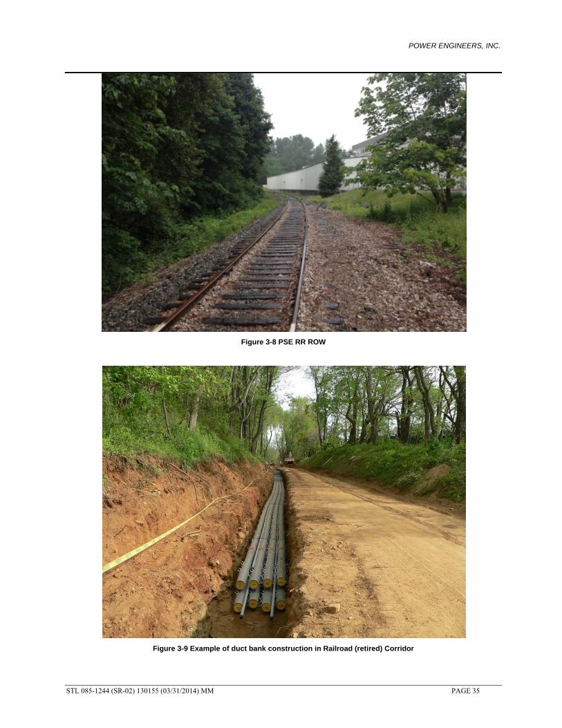
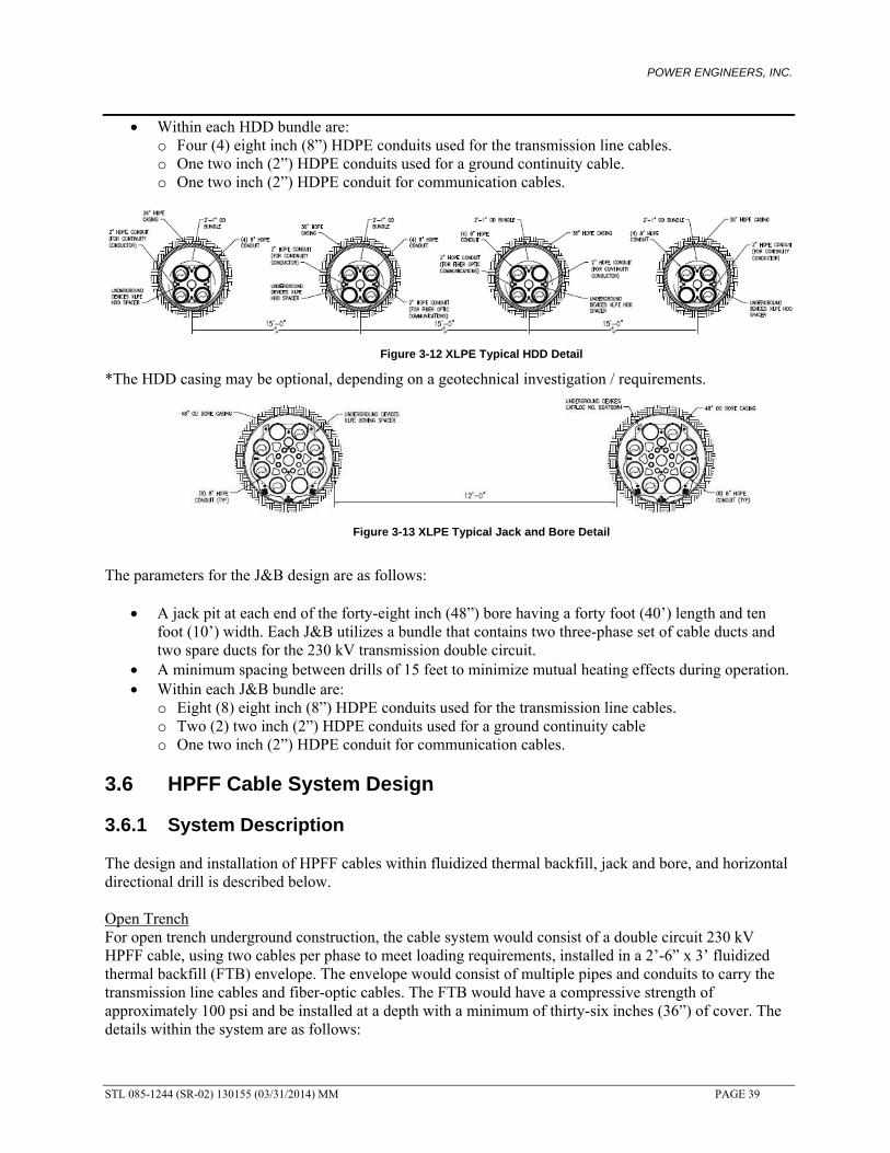
3.3 Review of Railroad Alternate PSE has acquired an easement along an existing railroad (RR) corridor in King County that might be available to use to install new underground transmission. Civil construction would also benefit by not having to perform significant grading of rolling terrain like the 115 kV ROW, and also lesson impact to the public by avoiding public roadway ROW. Figure 3-8 is a snapshot view of the RR ROW. An example of what the duct bank construction would look like in the RR corridor can be seen in Figure 3-9. This example is from a project in Virginia that contained a retired railroad already converted into a hiker/biker trial. A new 230 kV cable system was installed within the existing trail. Note; the photograph is only for one circuit – PSE would need a second duct bank installed within the easement for the other transmission line.
POWER ENGINEERS, INC.
STL 085-1244 (SR-02) 130155 (03/31/2014) MM PAGE 35
Figure 3-8 PSE RR ROW
Figure 3-9 Example of duct bank construction in Railroad (retired) Corridor

POWER ENGINEERS, INC.
STL 085-1244 (SR-02) 130155 (03/31/2014) MM PAGE 36
The PSE RR routing options can be found in the conceptual route drawings in the appendix.
Major disadvantages with the RR ROW are: Location of the ROW with respect to the substations – the RR ROW is not close to the
existing 115 kV corridor (and associated substations) and routing along it is not logical due to the significant length it would add when compared to the other alternatives. The long segments would still have to be installed within roadways and increase the total construction costs.
Stability and size of ROW – there are areas of the ROW that become very narrow (less than 40-ft) which would complicate civil construction and also cable installation. There are also steep side slopes (and inverted slopes) that would require grading for stability.
Multiple use corridor with other easement holders must also be accommodated. Due to changes in elevation, the railroad is on bridges in areas which are not conducive for
underground transmission installation. o A railroad bridge is located just south of the Lake Hills Connector due to grade elevation
changes. Underground construction would be challenging due to these profile changes as discussed previously.
3.3.1 Route Summary
Route Between Sammamish and Lakeside The route begins at Sammamish and continues to Willows Road NE. Then heads south on
148th Ave NE to Redmond Way, where the route continues west to Kirkland Way. At Kirkland Way, the route turns south and intersects the railroad right of way. The route would follow the Railroad to the northwest corner of the intersection of Highway 90 and 405, where the route crosses Highway 405 by HDD to SE 32nd St to Richard Rd to 30th St. to Lakeside.
Route is approximately 11.5 miles long. Majority of route is located on along the railroad right of way and Redmond Way. Crosses Highway 405 four times, two of which would require approximately 1200-ft and
2000-ft long HDD’s. Route Between Lakeside and Talbot Hill The route begins at Lakeside and heads west on SE 30th St to Richards Rd, where it turns south
until it turns west on SE 32nd St., then crosses under Highway 405 to intersect the railroad right of way. The route continues on the railroad right of way, eventually coming to Renton Ave. S to Beacon Way to Talbot Hill.
Route is approximately 9.8 miles long. Majority of route is located on along the railroad right of way. Crosses Highway 405 twice (one 1200 ft HDD required) and Highway 90 once with a 1000 ft
HDD. 3.3.2 Easement & Construction Requirements The railroad alternate route currently has abandoned ROW that varies from 100 feet to less than 40 feet. The easement requirements for the underground transmission line along the railroad route are similar to the requirements described in the review of the existing PSE 115 kV easement.
3.4 Review of Seattle City Light Tap Alternate PSE has requested that one double circuit 230 kV alignment “tap in” to the existing 230 kV Seattle City Light (SCL) system with underground transmission near the Highway 405 and Highway 90 intersection,

POWER ENGINEERS, INC.
STL 085-1244 (SR-02) 130155 (03/31/2014) MM PAGE 37
and be routed to Lakeside. Likewise, double circuit 230 kV underground transmission lines would also “tap out” from Lakeside to the same lines. Both alignments would leave Lakeside on SE 30th St. to Richards road. There, one alignment would turn north to SE 26th Pl., and tie into the existing SCL lines at 124th Ave. SE. The other alignment would turn south to SE 32nd St., and tie into the existing SCL lines at 125th Ave. SE. The SE 26th Pl. route is about 1.2 miles in length, while the SE 32nd St. route is about 0.8 miles in length. Both of these routes are considered to be suburban type construction, and have similar challenges as described in the street alternate. For an HPFF cable system, the taps would be made at transition stations. For an XLPE cable system, the taps could be accomplished with riser structures used to intercept the existing SCL lines. Figure 3-10 is an example of a double circuit 230 kV overhead to underground riser structure. Each structure contains two underground cables per phase to match the overhead line rating.
Figure 3-10 Typical 230 kV Riser Structure

POWER ENGINEERS, INC.
STL 085-1244 (SR-02) 130155 (03/31/2014) MM PAGE 38
3.5 XLPE Cable System Design
3.5.1 System Description Open Trench For open trench underground construction, the cable system would consist of a double circuit 230 kV XLPE cable, using two cables per phase to meet loading requirements, installed in a 2’-3” x 4’-0” concrete encased duct bank. The duct bank would consist of multiple conduits to carry the transmission line cables and grounding cables. The concrete duct bank would have a compressive strength of 3000 psi and be installed at a depth to provide a minimum of thirty-six inches (36”) of cover. The conduit details within the duct bank are as follows:
Eight (8) eight inch (8”) schedule 40 PVC conduits used for the transmission line cable per circuit. Initially, six out of the eight 8” conduits would have cable installed, allowing for two spare conduits.
One (1) two inch (2”) schedule 40 PVC conduit installed for ground continuity cable per circuit. One (1) two inch (2”) schedule 40 PVC conduit installed for communication cable per circuit.
The final duct bank size and layout would be determined during final design based on PSE’s final design criteria. Factors to be considered are electrical requirements, heat dissipation, minimal burial depths, existing facility/utility locations and cable installation requirements. Figure 3-11 shows a typical trench detail and installation cross section.
Figure 3-11 XLPE Typical Trench Detail
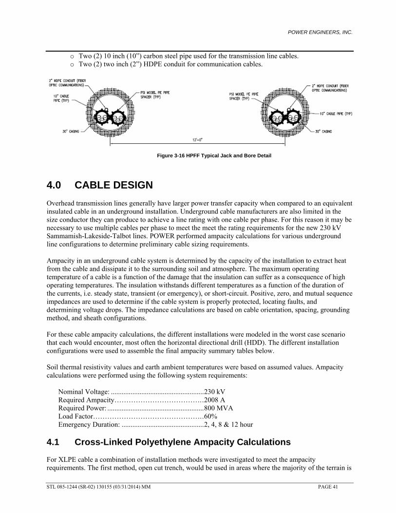
Trenchless Two possible trenchless methods for crossing difficult terrain are the horizontal directional drilling method and also the jack and bore (J&B) method. These methods require a transition from the open trench installation to the desired trenchless arrangement. Figure 3-12 and 3-13 show the proposed HDD and J&B conduit arrangements. The bored designs would contain high density polyethylene conduits that are joined by fusion welding to allow for the tensions seen while the conduits are pulled into a borehole. The parameters for these HDD designs are as follows:
Four horizontal directional drills, utilizing a 25-inch diameter bundle. Each HDD contains one three-phase set of cable ducts and one spare duct for the 230 kV double circuit transmission lines.
A minimum spacing between drills of 15 feet to minimize mutual heating effects during operation.
POWER ENGINEERS, INC.
STL 085-1244 (SR-02) 130155 (03/31/2014) MM PAGE 39
Within each HDD bundle are: o Four (4) eight inch (8”) HDPE conduits used for the transmission line cables. o One two inch (2”) HDPE conduits used for a ground continuity cable. o One two inch (2”) HDPE conduit for communication cables.
Figure 3-12 XLPE Typical HDD Detail
*The HDD casing may be optional, depending on a geotechnical investigation / requirements.
Figure 3-13 XLPE Typical Jack and Bore Detail
The parameters for the J&B design are as follows:
A jack pit at each end of the forty-eight inch (48”) bore having a forty foot (40’) length and ten foot (10’) width. Each J&B utilizes a bundle that contains two three-phase set of cable ducts and two spare ducts for the 230 kV transmission double circuit.
A minimum spacing between drills of 15 feet to minimize mutual heating effects during operation. Within each J&B bundle are:
o Eight (8) eight inch (8”) HDPE conduits used for the transmission line cables. o Two (2) two inch (2”) HDPE conduits used for a ground continuity cable o One two inch (2”) HDPE conduit for communication cables.
3.6 HPFF Cable System Design 3.6.1 System Description The design and installation of HPFF cables within fluidized thermal backfill, jack and bore, and horizontal directional drill is described below. Open Trench For open trench underground construction, the cable system would consist of a double circuit 230 kV HPFF cable, using two cables per phase to meet loading requirements, installed in a 2’-6” x 3’ fluidized thermal backfill (FTB) envelope. The envelope would consist of multiple pipes and conduits to carry the transmission line cables and fiber-optic cables. The FTB would have a compressive strength of approximately 100 psi and be installed at a depth with a minimum of thirty-six inches (36”) of cover. The details within the system are as follows:

POWER ENGINEERS, INC.
STL 085-1244 (SR-02) 130155 (03/31/2014) MM PAGE 40
Two (2) 10 inch (10”) carbon steel pipes used for the transmission line cables per circuit. One (1) two inch (2”) HDPE conduit for communication per circuit.
The final trench size and layout would be determined during final design and would be based on PSE’s final design criteria. Like a solid dielectric cable system, factors to be considered are electrical requirements, heat dissipation, minimal burial depths, existing facility/utility locations and cable installation requirements. Figure 3-14 shows a typical trench detail.
Figure 3-14 HPFF Typical Trench Detail
Trenchless To accommodate the HDD design, a 0.375” thick wall design allows for an increased protection from kinking the pipe during pull-back operations. Figure 3-15 show the proposed HDD conduit arrangements for HPFF. The parameters of the HDD design are as follows:
Four horizontal directional drills, each HDD would contain one three-phase set of cables for the double circuit 230 kV transmission line.
A spacing between drills of 15 feet to minimize mutual heating effects during operation. One (1) 10 inch (10”) carbon steel pipe used for the transmission line cables for each HDD.
Figure 3-15 HPFF Typical HDD Detail
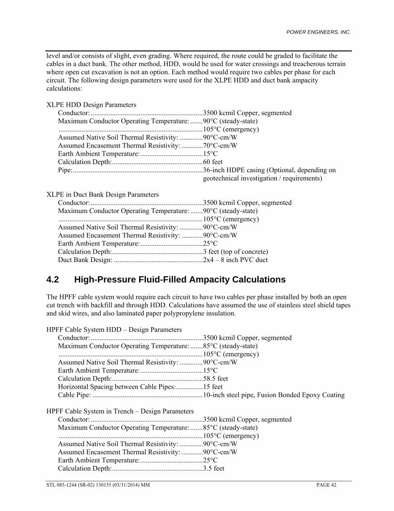
Figure 3-16 show the proposed J&B conduit arrangements for HPFF. The parameters for the J&B design are as follows:
A jack pit at each end of the thirty inch (30”) bore having a forty foot (40’) length and ten foot (10’) width. Each J&B utilizes a bundle that contains two three-phase cable pipes for the 230 kV transmission double circuit.
A minimum spacing between drills of 15 feet to minimize mutual heating effects during operation. Within each J&B bundle are:
POWER ENGINEERS, INC.
STL 085-1244 (SR-02) 130155 (03/31/2014) MM PAGE 41
o Two (2) 10 inch (10”) carbon steel pipe used for the transmission line cables. o Two (2) two inch (2”) HDPE conduit for communication cables.
Figure 3-16 HPFF Typical Jack and Bore Detail
4.0 CABLE DESIGN Overhead transmission lines generally have larger power transfer capacity when compared to an equivalent insulated cable in an underground installation. Underground cable manufacturers are also limited in the size conductor they can produce to achieve a line rating with one cable per phase. For this reason it may be necessary to use multiple cables per phase to meet the meet the rating requirements for the new 230 kV Sammamish-Lakeside-Talbot lines. POWER performed ampacity calculations for various underground line configurations to determine preliminary cable sizing requirements. Ampacity in an underground cable system is determined by the capacity of the installation to extract heat from the cable and dissipate it to the surrounding soil and atmosphere. The maximum operating temperature of a cable is a function of the damage that the insulation can suffer as a consequence of high operating temperatures. The insulation withstands different temperatures as a function of the duration of the currents, i.e. steady state, transient (or emergency), or short-circuit. Positive, zero, and mutual sequence impedances are used to determine if the cable system is properly protected, locating faults, and determining voltage drops. The impedance calculations are based on cable orientation, spacing, grounding method, and sheath configurations. For these cable ampacity calculations, the different installations were modeled in the worst case scenario that each would encounter, most often the horizontal directional drill (HDD). The different installation configurations were used to assemble the final ampacity summary tables below. Soil thermal resistivity values and earth ambient temperatures were based on assumed values. Ampacity calculations were performed using the following system requirements: Nominal Voltage: .................................................... 230 kV Required Ampacity………………………………. . 2008 A Required Power: ...................................................... 800 MVA Load Factor………………………………………. . 60% Emergency Duration: .............................................. 2, 4, 8 & 12 hour
4.1 Cross-Linked Polyethylene Ampacity Calculations For XLPE cable a combination of installation methods were investigated to meet the ampacity requirements. The first method, open cut trench, would be used in areas where the majority of the terrain is
POWER ENGINEERS, INC.
STL 085-1244 (SR-02) 130155 (03/31/2014) MM PAGE 42
level and/or consists of slight, even grading. Where required, the route could be graded to facilitate the cables in a duct bank. The other method, HDD, would be used for water crossings and treacherous terrain where open cut excavation is not an option. Each method would require two cables per phase for each circuit. The following design parameters were used for the XLPE HDD and duct bank ampacity calculations: XLPE HDD Design Parameters Conductor: ............................................................... 3500 kcmil Copper, segmented Maximum Conductor Operating Temperature: ....... 90°C (steady-state) ................................................................................. 105°C (emergency) Assumed Native Soil Thermal Resistivity: ............. 90°C-cm/W Assumed Encasement Thermal Resistivity: ............ 70°C-cm/W Earth Ambient Temperature: ................................... 15°C Calculation Depth: ................................................... 60 feet Pipe: ......................................................................... 36-inch HDPE casing (Optional, depending on
geotechnical investigation / requirements) XLPE in Duct Bank Design Parameters Conductor: ............................................................... 3500 kcmil Copper, segmented Maximum Conductor Operating Temperature: ....... 90°C (steady-state) ................................................................................. 105°C (emergency) Assumed Native Soil Thermal Resistivity: ............. 90°C-cm/W Assumed Encasement Thermal Resistivity: ............ 90°C-cm/W Earth Ambient Temperature: ................................... 25°C Calculation Depth: ................................................... 3 feet (top of concrete) Duct Bank Design: .................................................. 2x4 – 8 inch PVC duct
4.2 High-Pressure Fluid-Filled Ampacity Calculations The HPFF cable system would require each circuit to have two cables per phase installed by both an open cut trench with backfill and through HDD. Calculations have assumed the use of stainless steel shield tapes and skid wires, and also laminated paper polypropylene insulation. HPFF Cable System HDD – Design Parameters Conductor: ............................................................... 3500 kcmil Copper, segmented Maximum Conductor Operating Temperature: ....... 85°C (steady-state) ................................................................................. 105°C (emergency) Assumed Native Soil Thermal Resistivity: ............. 90°C-cm/W Earth Ambient Temperature: ................................... 15°C Calculation Depth: ................................................... 58.5 feet Horizontal Spacing between Cable Pipes: ............... 15 feet Cable Pipe: .............................................................. 10-inch steel pipe, Fusion Bonded Epoxy Coating HPFF Cable System in Trench – Design Parameters Conductor: ............................................................... 3500 kcmil Copper, segmented Maximum Conductor Operating Temperature: ....... 85°C (steady-state) ................................................................................. 105°C (emergency) Assumed Native Soil Thermal Resistivity: ............. 90°C-cm/W Assumed Encasement Thermal Resistivity: ............ 90°C-cm/W
Earth Ambient Temperature: ................................... 25°C Calculation Depth: ................................................... 3.5 feet
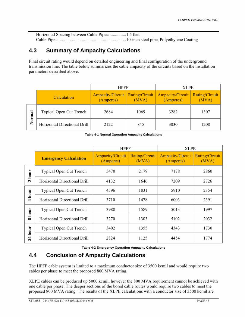
POWER ENGINEERS, INC.
STL 085-1244 (SR-02) 130155 (03/31/2014) MM PAGE 43
Horizontal Spacing between Cable Pipes: ............... 1.5 feet Cable Pipe: .............................................................. 10-inch steel pipe, Polyethylene Coating
4.3 Summary of Ampacity Calculations Final circuit rating would depend on detailed engineering and final configuration of the underground transmission line. The table below summarizes the cable ampacity of the circuits based on the installation parameters described above.
HPFF XLPE
Calculation Ampacity/Circuit
(Amperes) Rating/Circuit
(MVA) Ampacity/Circuit
(Amperes) Rating/Circuit
(MVA)
Nor
mal
Typical Open Cut Trench 2684 1069 3282 1307
Horizontal Directional Drill 2122 845 3030 1208
Table 4-1 Normal Operation Ampacity Calculations
HPFF XLPE
Emergency Calculation Ampacity/Circuit
(Amperes) Rating/Circuit
(MVA) Ampacity/Circuit
(Amperes) Rating/Circuit
(MVA)
2 h
our Typical Open Cut Trench 5470 2179 7178 2860
Horizontal Directional Drill 4132 1646 7209 2726
4 h
our Typical Open Cut Trench 4596 1831 5910 2354
Horizontal Directional Drill 3710 1478 6003 2391
8 h
our Typical Open Cut Trench 3988 1589 5013 1997
Horizontal Directional Drill 3270 1303 5102 2032
24 h
our Typical Open Cut Trench 3402 1355 4343 1730
Horizontal Directional Drill 2824 1125 4454 1774
Table 4-2 Emergency Operation Ampacity Calculations
4.4 Conclusion of Ampacity Calculations The HPFF cable system is limited to a maximum conductor size of 3500 kcmil and would require two cables per phase to meet the proposed 800 MVA rating. XLPE cables can be produced up 5000 kcmil, however the 800 MVA requirement cannot be achieved with one cable per phase. The deeper sections of the bored cable routes would require two cables to meet the proposed 800 MVA rating. The results of the XLPE calculations with a conductor size of 3500 kcmil are

POWER ENGINEERS, INC.
STL 085-1244 (SR-02) 130155 (03/31/2014) MM PAGE 44
0
10
-25 -20 -15 -10 -5 0 5 10 15 20 25
Mag
net
ic F
ield
Str
eng
th (
mG
)
Distance from Center of Right of Way (feet)
Double Circuit HPFF, 800 MVA
somewhat higher than the equivalent HPFF which would mean that a smaller conductor size could most likely be used. Detailed engineering would be required to confirm the assumptions of this study and whether or not a smaller conductor size would meet the ampacity requirements, and provide overall cost savings compared to 3500 kcmil cables.
4.5 High-Pressure Fluid-Filled System Calculations The HPFF cable system calculations use specific cable properties and the following system criterion: Cable Configuration ................................................ Cradled Assumed Fault Current…………………………… 40,000 A Calculation Method: ................................................ Neher 1964
HPFF Cable System Calculations (per 1000 ft) (per circuit)
Positive / Negative Self Impedance 0.0039 + j 0.0214 Ω
Zero Sequence Self Impedance 0.0274+ j 0.0418 Ω
Reactive Charging Power 1.5 MVAR
Capacitance 0.23 µF
Charging Current 11.5 A
Maximum Electromagnetic Field (EMF)* 2.1 mG
*Calculation performed at 1 m above ground Table 4-3 HPFF System Calculations
Electric and Magnetic field intensities were calculated at one (1) meter above grade, at a standard three (3) foot trench depth, and at an 800 MVA rating.

POWER ENGINEERS, INC.
STL 085-1244 (SR-02) 130155 (03/31/2014) MM PAGE 45
0
10
20
30
40
50
60
70
80
90
100
-25 -20 -15 -10 -5 0 5 10 15 20 25
Mag
net
ic F
ield
Str
eng
th (
mG
)
Distance from Center of Right of Way (feet)
Double Circuit XLPE, 800 MVA
4.6 Cross-linked Polyethylene System Calculations The XLPE cable system calculations use specific cable properties and the following system criterion: Bonding Method: ..................................................... Single Point Ground Continuity Conductor: ................................ Round Copper Shield Configuration............................... ................ Copper laminate, w/ concentric wires Cable Spacing: ......................................................... 1.5 ft Calculation Method: ................................................ Generalized Matrix calculation
XLPE Cable System Calculations (per 1000 ft) (per circuit)
Positive / Negative Self Impedance 0.001957 + j 0.031 Ω
Zero Sequence Self Impedance 0.045 + j 0.113 Ω
Zero Mutual Impedance 0.019 + j 0.019 Ω
Reactive Charging Power 0.906 MVAR
Capacitance 0.136 µF
Charging Current 6.83 A
Maximum Electromagnetic Field (EMF)* 93.3 mG
*Calculation performed at 1 m above ground Table 4-4 XLPE System Calculations
Electric and Magnetic field intensities were calculated at one (1) meter above grade, at a standard three (3) foot trench depth, and at an 800 MVA rating.

POWER ENGINEERS, INC.
STL 085-1244 (SR-02) 130155 (03/31/2014) MM PAGE 46
5.0 COST ESTIMATES & SCHEDULE The cost estimate is based on pricing obtained from recent underground projects. There are many factors that affect the overall cost of an underground project. These factors are:
1. Cost of materials. 2. Contractor/Manufacturer availability.
3. Subsurface conditions. The type and depth of soil and rock that must be excavated to place the cable can dramatically impact the cost. For example, construction costs in rock formations are significantly higher than construction costs in clay soils. The presence of existing underground facilities also presents a significant uncertainty when estimating the cost of an underground project.
5.1 Cost Estimate Assumptions
1. Materials used in the cost estimates meet all applicable industry standards. 2. Construction would be performed by qualified craftsmen experienced in installing high voltage
XLPE or HPFF underground transmission systems. 3. Due to the volatility of material costs, these estimates are subject to market fluctuations. 4. Costs to obtain all environmental, local, state, and federal permits and mitigation as required are
not included. 5. Costs to obtain all necessary right-of-way, easement, and property as required are not included. 6. No spare cable or parts have been included in the estimates. 7. A 25% contingency has been included. 8. Single point bonding of XLPE cable sheaths were assumed. 9. Material and labor costs reflect the installation of a double circuit 230 kV XLPE duct bank system,
two cables per phase, including associated termination structures at each terminal. A double circuit 230kV HPFF cable system would require two cables per phase without forced cooling equipment.
10. Costs to install a fiber optic cable for communication are included. However, the installation of temperature monitoring equipment for the cable system is not included.
11. Substation engineering and construction costs for are not included. 12. Costs for reactive compensation are not included. A system study would need to be conducted to
determine the detailed engineering and construction requirements for reactive compensation, if required.
13. Trenchless installation costs assume drilling through favorable soils (non-rock). 14. Engineering has assumed to be 2% of the total construction costs. 15. PSE overhead costs and taxes are not included.

POWER ENGINEERS, INC.
STL 085-1244 (SR-02) 130155 (03/31/2014) MM PAGE 47
5.2 Summary of Cost Estimates Tables 5-1 through 5-6 are summaries of the costs for the XLPE and HPFF designs for each route. A detailed breakdown of each estimate by section is in the appendix.
Table 5-1 XLPE Sammamish to Lakeside
Table 5-2 HPFF Sammamish to Lakeside
Table 5-3 XLPE Lakeside to Talbot Hill
Table 5-4 HPFF Lakeside to Talbot Hill
ROUTE LENGTH (miles) MATERIALSLABOR &
EQUIPMENTTOTAL
EXISTING OH EASEMENT 7.2 $99,227,667 $63,204,394 $162,432,061
RAILROAD ROW 11.5 $185,268,917 $121,024,488 $306,293,405
STREET ROW 7.9 $126,138,585 $78,666,269 $204,804,854
ROUTE LENGTH (miles) MATERIALSLABOR &
EQUIPMENTTOTAL
EXISTING OH EASEMENT 7.2 $126,930,307 $57,382,537 $184,312,844
RAILROAD ROW 11.5 $219,448,652 $99,410,092 $318,858,744
STREET ROW 7.9 $153,824,834 $69,954,364 $223,779,198
SECTION LENGTH (miles) MATERIALSLABOR &
EQUIPMENTTOTAL
EXISTING OH EASEMENT 9.5 $139,292,708 $89,854,873 $229,147,580
RAILROAD 9.8 $146,205,595 $94,645,367 $240,850,961
STREET ROW 10.7 $168,795,920 $104,655,554 $273,451,473
SECTION LENGTH (miles) MATERIALSLABOR &
EQUIPMENTTOTAL
EXISTING OH EASEMENT 9.5 $171,890,752 $78,145,160 $250,035,912
RAILROAD 9.8 $179,117,547 $81,286,975 $260,404,521
STREET ROW 10.7 $205,609,217 $94,013,482 $299,622,699
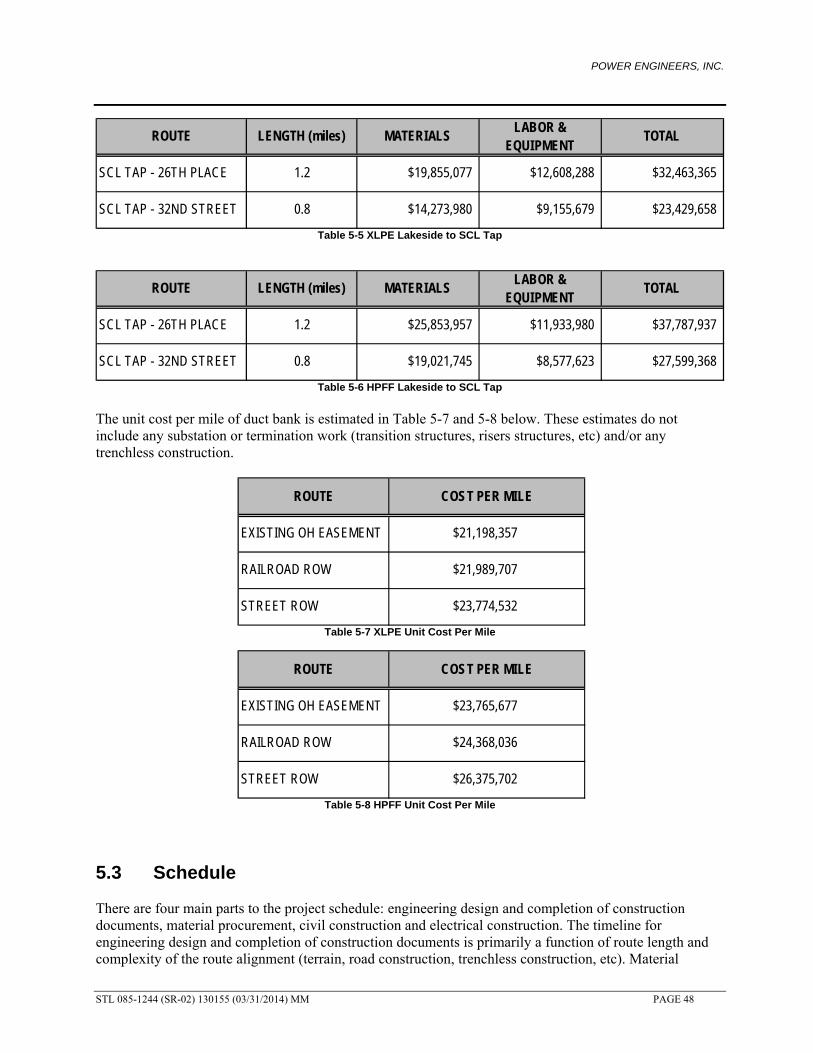
POWER ENGINEERS, INC.
STL 085-1244 (SR-02) 130155 (03/31/2014) MM PAGE 48
Table 5-5 XLPE Lakeside to SCL Tap
Table 5-6 HPFF Lakeside to SCL Tap
The unit cost per mile of duct bank is estimated in Table 5-7 and 5-8 below. These estimates do not include any substation or termination work (transition structures, risers structures, etc) and/or any trenchless construction.
Table 5-7 XLPE Unit Cost Per Mile
Table 5-8 HPFF Unit Cost Per Mile
5.3 Schedule There are four main parts to the project schedule: engineering design and completion of construction documents, material procurement, civil construction and electrical construction. The timeline for engineering design and completion of construction documents is primarily a function of route length and complexity of the route alignment (terrain, road construction, trenchless construction, etc). Material
ROUTE LENGTH (miles) MATERIALSLABOR &
EQUIPMENTTOTAL
SCL TAP - 26TH PLACE 1.2 $19,855,077 $12,608,288 $32,463,365
SCL TAP - 32ND STREET 0.8 $14,273,980 $9,155,679 $23,429,658
ROUTE LENGTH (miles) MATERIALSLABOR &
EQUIPMENTTOTAL
SCL TAP - 26TH PLACE 1.2 $25,853,957 $11,933,980 $37,787,937
SCL TAP - 32ND STREET 0.8 $19,021,745 $8,577,623 $27,599,368
ROUTE COST PER MILE
EXISTING OH EASEMENT $21,198,357
RAILROAD ROW $21,989,707
STREET ROW $23,774,532
ROUTE COST PER MILE
EXISTING OH EASEMENT $23,765,677
RAILROAD ROW $24,368,036
STREET ROW $26,375,702
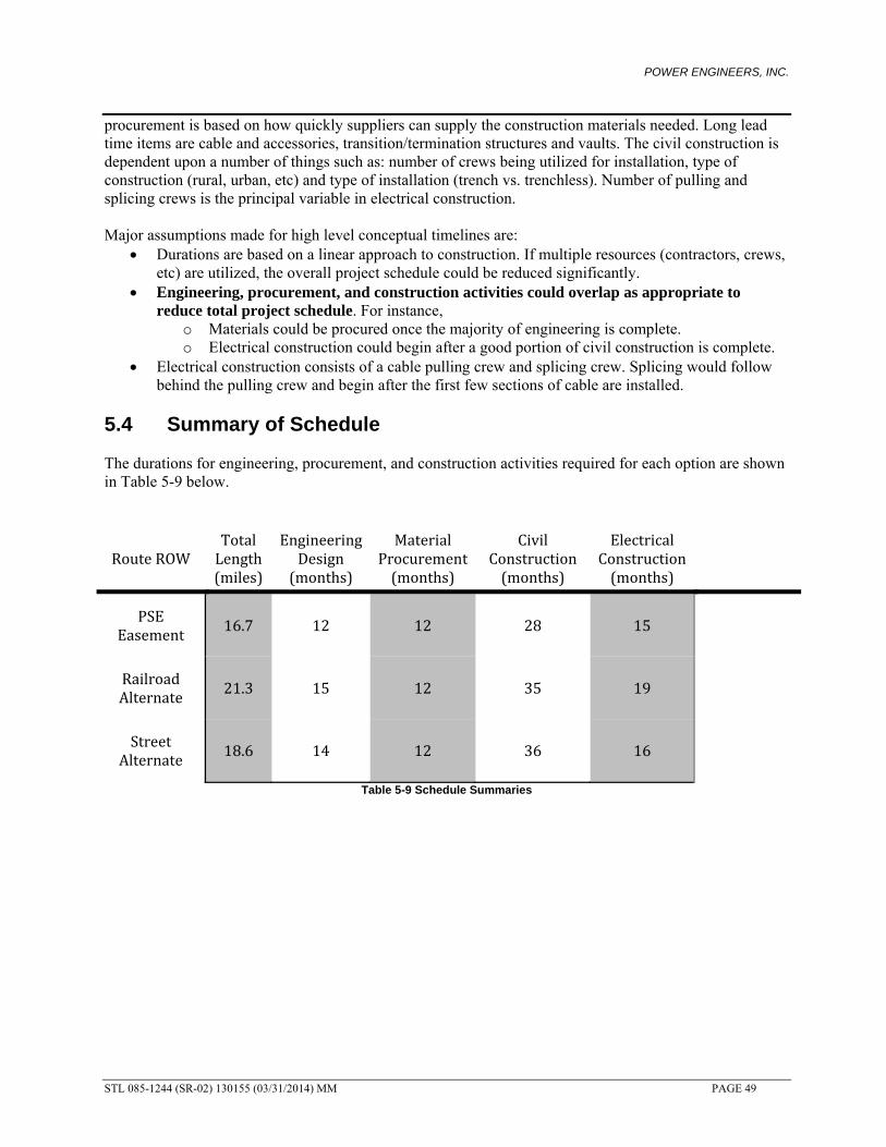
POWER ENGINEERS, INC.
STL 085-1244 (SR-02) 130155 (03/31/2014) MM PAGE 49
procurement is based on how quickly suppliers can supply the construction materials needed. Long lead time items are cable and accessories, transition/termination structures and vaults. The civil construction is dependent upon a number of things such as: number of crews being utilized for installation, type of construction (rural, urban, etc) and type of installation (trench vs. trenchless). Number of pulling and splicing crews is the principal variable in electrical construction. Major assumptions made for high level conceptual timelines are:
Durations are based on a linear approach to construction. If multiple resources (contractors, crews, etc) are utilized, the overall project schedule could be reduced significantly.
Engineering, procurement, and construction activities could overlap as appropriate to reduce total project schedule. For instance,
o Materials could be procured once the majority of engineering is complete. o Electrical construction could begin after a good portion of civil construction is complete.
Electrical construction consists of a cable pulling crew and splicing crew. Splicing would follow behind the pulling crew and begin after the first few sections of cable are installed.
5.4 Summary of Schedule The durations for engineering, procurement, and construction activities required for each option are shown in Table 5-9 below.
RouteROW TotalLength(miles)
EngineeringDesign(months)
MaterialProcurement(months)
CivilConstruction(months)
ElectricalConstruction(months)
PSEEasement
16.7 12 12 28 15
RailroadAlternate
21.3 15 12 35 19
StreetAlternate
18.6 14 12 36 16
Table 5-9 Schedule Summaries

POWER ENGINEERS, INC.
STL 085-1244 (SR-02) 130155 (03/31/2014) MM PAGE 50
APPENDIX A
Aerial Route Drawings
POWER ENGINEERS, INC.
STL 085-1244 (SR-02) 130155 (03/31/2014) MM PAGE 51
APPENDIX B
Typical Detail Drawings