underground trans 00 me yeu of t
TRANSCRIPT

7/28/2019 Underground Trans 00 Me Yeu of t
http://slidepdf.com/reader/full/underground-trans-00-me-yeu-of-t 1/327
7/28/2019 Underground Trans 00 Me Yeu of t
http://slidepdf.com/reader/full/underground-trans-00-me-yeu-of-t 2/327
7/28/2019 Underground Trans 00 Me Yeu of t
http://slidepdf.com/reader/full/underground-trans-00-me-yeu-of-t 3/327
7/28/2019 Underground Trans 00 Me Yeu of t
http://slidepdf.com/reader/full/underground-trans-00-me-yeu-of-t 4/327
7/28/2019 Underground Trans 00 Me Yeu of t
http://slidepdf.com/reader/full/underground-trans-00-me-yeu-of-t 5/327
4.<;
UNDERGROUND TRANSMISSIONAND
DISTRIBUTION
7/28/2019 Underground Trans 00 Me Yeu of t
http://slidepdf.com/reader/full/underground-trans-00-me-yeu-of-t 6/327
'MsQraw-JJillBock Qx7mPUBLISHERS OF BOOKS FO K^
Coal Age ^ Electric Railway Journal
Electrical World v Engineering News-Record
American Machinist v Ingenieria Intemacional
Engineering 8 Mining Journal '=' Power
Chemical 6 Metallurgical Engineering
Electrical Merchandising
7/28/2019 Underground Trans 00 Me Yeu of t
http://slidepdf.com/reader/full/underground-trans-00-me-yeu-of-t 7/327
UNDERGROUND
TRANSMISSION ANDDISTRIBUTION
FOR
ELECTRIC LIGHT AND POWER
BY
E. B. MEYERMEMBER AMERICAN INSTITUTE OP ELECTRICAL ENGINEERS; MEMBER AMERICAN
SOCIETY OP MECHANICAL ENGINEERS; MEMBER AMERICAN ELECTRIC RAIL-
WAY association; member national electric LIGHT association;
CHAIRMAN, N. E. L. A. COMMITTEE ON UNDERGROUND CONSTRUCTIONAND ELECTROLYSIS, 1915-1916
First Edition
Second Impression
McGRAW-HILL BOOK COMPANY, Inc.
NEW YORK: 239 WEST 39TH STREET
LONDON: 6 & 8 BOUVERIE ST., E. C. 4
1916
7/28/2019 Underground Trans 00 Me Yeu of t
http://slidepdf.com/reader/full/underground-trans-00-me-yeu-of-t 8/327
3 >f
TK3351
Copyright, 1916, by the
McGraw-Hill Book Company, Inc.
Xaa MAFI<B PRBSS TOXK FA
7/28/2019 Underground Trans 00 Me Yeu of t
http://slidepdf.com/reader/full/underground-trans-00-me-yeu-of-t 9/327
7/28/2019 Underground Trans 00 Me Yeu of t
http://slidepdf.com/reader/full/underground-trans-00-me-yeu-of-t 10/327
VI PREFACE
and many photographs and cuts, and is indebted to Messrs.
J. T. Foster, H. S. Vassar and Paul Liipke for valuable sugges-
tions received during the preparation of the manuscript.
E. B. Meyer.Newark, N. J.,
November, 1916.

7/28/2019 Underground Trans 00 Me Yeu of t
http://slidepdf.com/reader/full/underground-trans-00-me-yeu-of-t 11/327
CONTENTSPaqb
Preface ' v
CHAPTER I
Historical 1
Periods of Development—Built-in Systems—Drawing-in Sys-
tems—Present Forms of Construction.
CHAPTER II
Preliminary Survey 19
Planning the System—Maps—Test Holes—Permits and Right-of-
way—Form of Agreement—Regulations.
CHAPTER III
Conduit and Manhole Construction 30
Selection of Materials—Installation of Conduit—Concrete—Tile
Duct—Stone Duct—Fibre Duct—Manhole Construction—Sewerand Illuminating Gas—Sealing Ducts in Manholes—Types of Man-
hole Construction—Building Manholes in Quicksand—Roof Con-
struction—Types of Covers—Waterproofing Manholes—Design of
Manholes for Transmission and Distribution—Transformer Man-
holes—Concrete Manhole Forms—Distribution Manholes—Cable
Tunnels—Specification and Contract—Form of Specification, Con-
tract and Bond—Construction Costs.
CHAPTER IV
Methods of Distribution 81
Street Distribution—Interior Block Distribution—Sidewalk Dis-
tribution—Duct Arrangement—Parallel Routing—Solid System
Service Connections—Armored-cable System—InstaUing Steel-
Taped Street-lighting Cable—Comparative Costs of Installation.
CHAPTER V
Cables 102
General—Terminology—Conductors—Insula ting Wall—RubberInsulation—Paper Insulation—Varnished Cambric Insulation
Graded Insulation—^Lead Covering—Types of Cables—Diameter
and Length of Cables—Fibre Core Cables—Transmission Cables
General Data—Sector Cable—Submarine Cable—Specifications,
General—Rubber Cable Specifications—Paper Cable Specifications
—High Tension Cable Specifications—Moisture in Cable Insulation.
7/28/2019 Underground Trans 00 Me Yeu of t
http://slidepdf.com/reader/full/underground-trans-00-me-yeu-of-t 12/327
viii CONTENTS
CHAPTER VIPaoe
Installation op Cables 151
Handling Lead Cables—Choice of Ducts—Rodding Ducts
Obstructions in Ducts—Drawing-in Cables—Cable-pulling Grips
Draw Rope—Drawing Apparatus—Power Trucks—Slack—Joint-
ing Cables—General Directions for Jointing—Jointing Rubber-
insulated Cables—Jointing Armored Cables—Paper and Cambric
Tape Joints—Paper Tube Joints—Advantages of Paper Tube
Joints—Sleeve Filling Material—Conducell Cable Joint Insulators
—High-voltage Vacuum Joint—Unit Package of Joint Material
—Protection of Cables in Manholes—Current-carrying Capacity
of Cables
—Cooling Duct Lines
—Connections to Overhead Lines
Lightning Arresters—Splicing Equipment, Tools and Safety
Devices.
CHAPTER VII
Testing Cables 227
International Electrical Units—Standardization Rules—Electrical
Tests—Insulation Resistance—Electrostatic Capacity—Capacity
of Testing Apparatus—^Locating and Repairing Cable Failures
Loop Test—Fault-locating Equipment—Periodic High-potential
Testing.
CHAPTER VIII
Distribution Systems and Auxiliary Equipment 241
General—Alternating-current Distribution—Single-phase System
—Two-phase Systems—Three-phase Systems—Secondary Mains
Underground Transformers—Cable Junction Boxes—Service Bus
—Manhole Oil Switches—A. C. Network Protector—Service Con-
nections from Underground Mains—Armored Services—Protection
of Transmission Systems—Relays—Current Limiting Reactance
Coils—Selective Fault Localizer—Arcing Ground Suppressor
Grounded Neutral Systems—Merz System of Cable Protection.
CHAPTER IX
Electrolysis 281
General—Drainage Systems—Protective Coatings—Insulating
Joints—Protecting Cable Sheaths—General Practice—Coopera-
tion of Utilities—Electrolysis Surveys.
CHAPTER X
Operation and Maintenance 296
Records—Identification of Cables—Record of Cable and Equip-
ment Failures—Cleaning Manholes—Care of Cables—Bonding
Cables in Manholes—Rules and Requirements.
Index 309
7/28/2019 Underground Trans 00 Me Yeu of t
http://slidepdf.com/reader/full/underground-trans-00-me-yeu-of-t 13/327
UNDERGROUND TRANSMISSIONAND DISTRIBUTION
CHAPTER I
fflSTORICAL
Periods of Development.—For a number of years after electric
lighting was first introduced, the distribution of current was
effected almost entirely by means of overhead wires carried on
poles. The development in many of the large cities where the
early market for electricity was found, proceeded at such a rapid
rate that it soon became practically impossible to take care of-
the number and size of feeders required for distribution by means
of overhead construction.
Large amounts of money had been expended in attempting
to beautify various cities, but these improvements were offset
to a great extent by the erection of unsightly overhead lines.
To remedy this condition and eliminate the fire hazard, it was
reaUzed by engineers that some other form of construction would
be necessary.
When the idea was first conceived of relieving the streets and
boulevards of the presence of electric wires, by placing them
underground, there were few engineers who believed the innova-
tion practicable, either from the viewpoint of service or economy.
The cry immediately arose that the first cost of an underground
installation would be prohibitive and it was firmly believed that
the efficiency and capacity of the wires would be greatly lessened.
This view was supported by the failures which attended the early
attempts to bury electric wires.
The earhest recorded attempt to lay a cable in the United
States for the purpose of transmitting an electric current appears
to be that made by Samuel F. B. Morse on Oct. 18, 1842. That
evening he hired a boat at the Battery water front, in New York,
and paid out a reel of copper wire laboriously insulated with
pitch, tar and rubber, as he was being rowed to Governor's
Island. He set up and prepared to demonstrate his electromag-
1
7/28/2019 Underground Trans 00 Me Yeu of t
http://slidepdf.com/reader/full/underground-trans-00-me-yeu-of-t 14/327
2 UNDERGROUND TRANSMISSION AND DISTRIBUTION
netic telegraph instruments at Castle Garden and the Island on
the following day. Only a few signals had been exchanged,
however, when an anchor fouled the cable, and it was cut byignorant sailors who dragged it up. Thus this first effort ended
in failure.
After strenuous exertion Morse secured from Congress, on the
last day of the session, March 3, 1843, an appropriation of
$30,000 "to test the practicability and efficacy" of his telegraph
system. He decided on a line from Washington to Baltimore
and planned to use underground construction, supposing that
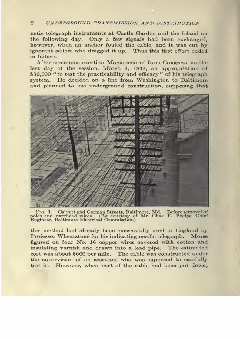
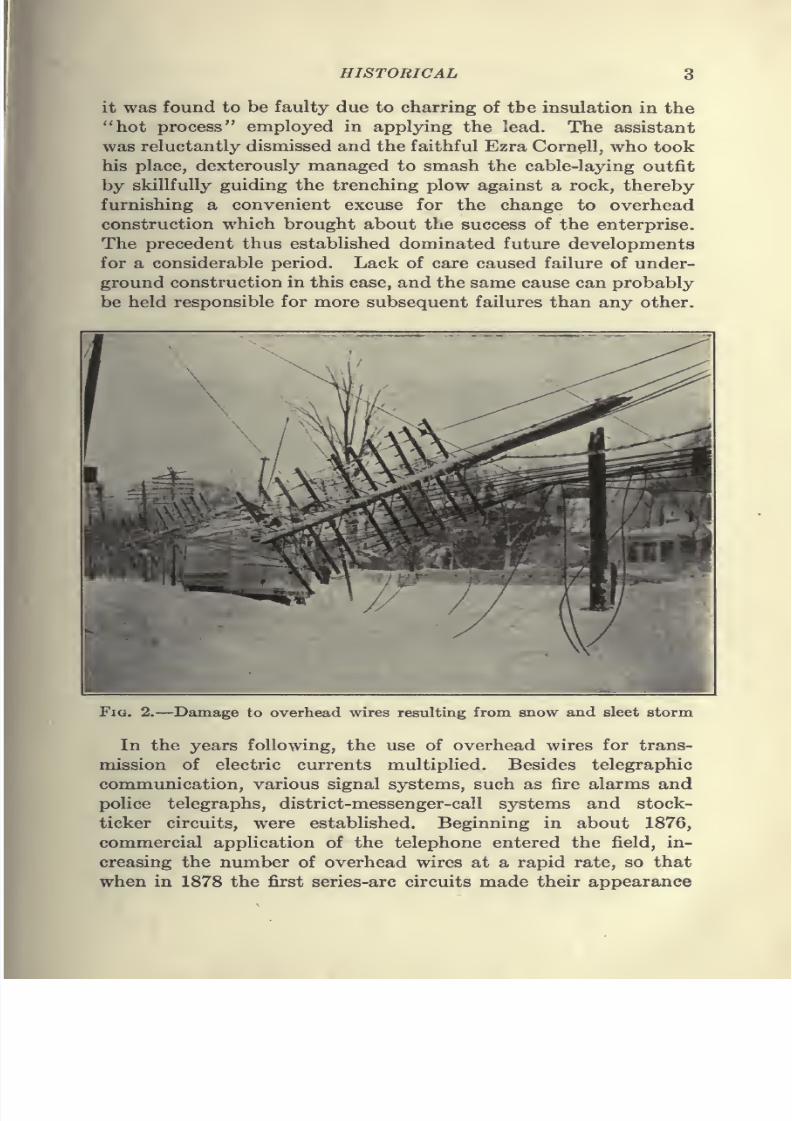
Fig. 1.—Calvert and German Streets, Baltimore, Md. Before removal of
poles and overhead wires. (By courtesy of Mr. Chas. E. Phelps, Chief
Engineer, Baltimore Electrical Commission.)
this method had already been successfully used in England by
Professor Wheatstone for his indicating needle telegraph. Morse
figured on four No. 16 copper wires covered with cotton and
insulating varnish and drawn into a lead pipe. The estimated
cost was about $600 per mile. The cable was constructed under
the supervision of an assistant who was supposed to carefully
test it. However, when part of the cable had been put down,
7/28/2019 Underground Trans 00 Me Yeu of t
http://slidepdf.com/reader/full/underground-trans-00-me-yeu-of-t 15/327
HISTORICAL 3
it was found to be faulty due to charring of the insulation in the
"hot process" employed in applying the lead. The assistant
was reluctantly dismissed and the faithful Ezra Cornell,
whotook
his place, dexterously managed to smash the cable-laying outfit
by skillfully guiding the trenching plow against a rock, thereby
furnishing a convenient excuse for the change to overhead
construction which brought about the success of the enterprise.
The precedent thus established dominated future developments
for a considerable period. Lack of care caused failure of under-
ground construction in this case, and the same cause can probably
beheld responsible for more subsequent failures
than anyother.
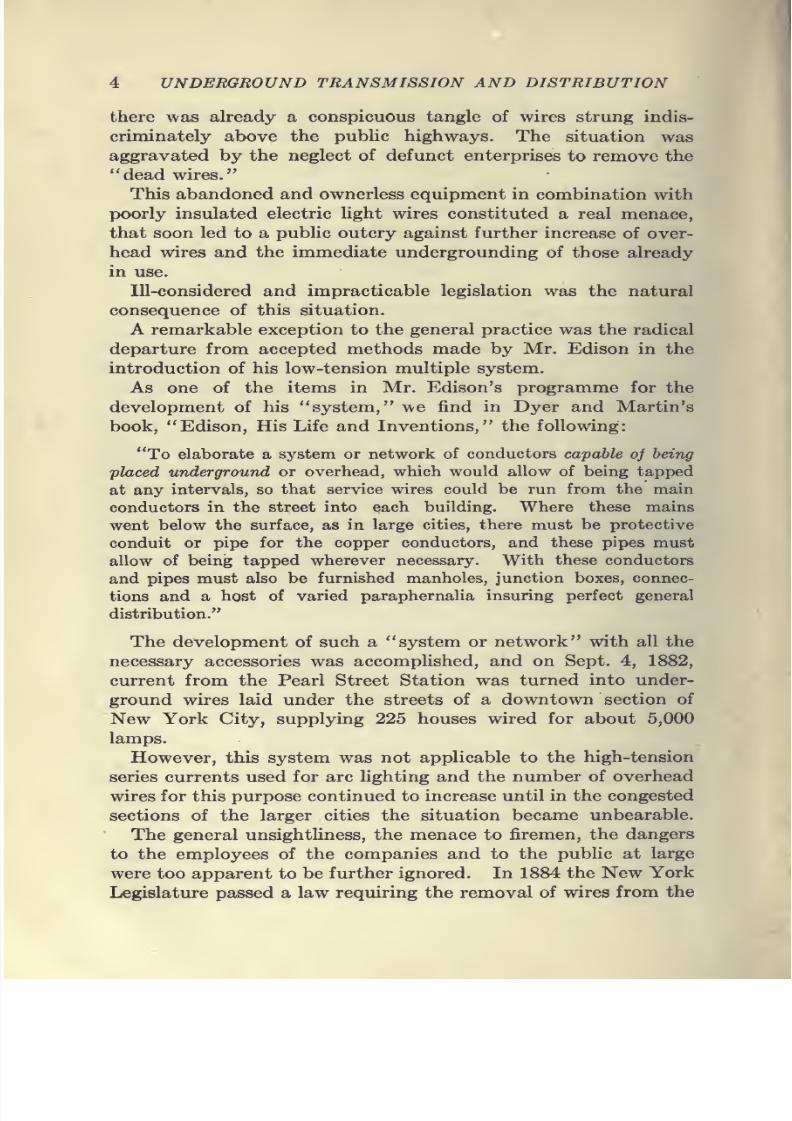
Fig. 2.—Damage to overhead wires resulting from snow and sleet storm
In the years following, the use of overhead wires for trans-
mission of electric currents multiplied. Besides telegraphic
communication, various signal systems, such as fire alarms and
police telegraphs, district-messenger-call systems and stock-
ticker circuits, were estabhshed. Beginning in about 1876,
commercial application of the telephone entered the field, in-
creasing the number of overhead wires at a rapid rate, so that
when in 1878 the first series-arc circuits made their appearance
7/28/2019 Underground Trans 00 Me Yeu of t
http://slidepdf.com/reader/full/underground-trans-00-me-yeu-of-t 16/327
4 UNDERGROUND TRANSMISSION AND DISTRIBUTION
there was already a conspicuous tangle of wires strung indis-
criminately above the public highways. The situation was
aggravated by the neglect of defunct enterprises to remove the
"dead wires."
This abandoned and ownerless equipment in combination with
poorly insulated electric light wires constituted a real menace,
that soon led to a public outcry against further increase of over-
head wires and the immediate undergrounding of those already
in use.
Ill-considered and impracticable legislation was the natural
consequence of this situation.
A remarkable exception to the general practice was the radical
departure from accepted methods made by Mr. Edison in the
introduction of his low-tension multiple system.
As one of the items in Mr. Edison's programme for the
development of his "system, "we find in Dyer and Martin's
book, "Edison, His Life and Inventions," the following:
"To elaborate a system or network of conductors capable oj being
placed underground or overhead, which would allow of being tapped
at any intervals, so that service wires could be run from the main
conductors in the street into each building. Where these mains
went below the surface, as in large cities, there must be protective
conduit or pipe for the copper conductors, and these pipes must
allow of being tapped wherever necessary. With these conductors
and pipes must also be furnished manholes, junction boxes, connec-
tions and a host of varied paraphernalia insuring perfect general
distribution."
The development of such a "system or network" with all the
necessary accessories was accomplished, and on Sept. 4, 1882,
current from the Pearl Street Station was turned into under-
ground wires laid under the streets of a downtown section of
New York City, supplying 225 houses wired for about 5,000
lamps.
However, this system was not applicable to the high-tension
series currents used for arc lighting and the number of overhead
wires for this purpose continued to increase until in the congested
sections of the larger cities the situation became unbearable.
The general unsightliness, the menace to firemen, the dangers
to the employees of the companies and to the public at large
were too apparent to be further ignored. In 1884 the New York
Legislature passed a law requiring the removal of wires from the
7/28/2019 Underground Trans 00 Me Yeu of t
http://slidepdf.com/reader/full/underground-trans-00-me-yeu-of-t 17/327
7/28/2019 Underground Trans 00 Me Yeu of t
http://slidepdf.com/reader/full/underground-trans-00-me-yeu-of-t 18/327
7/28/2019 Underground Trans 00 Me Yeu of t
http://slidepdf.com/reader/full/underground-trans-00-me-yeu-of-t 19/327
HISTORICAL 7
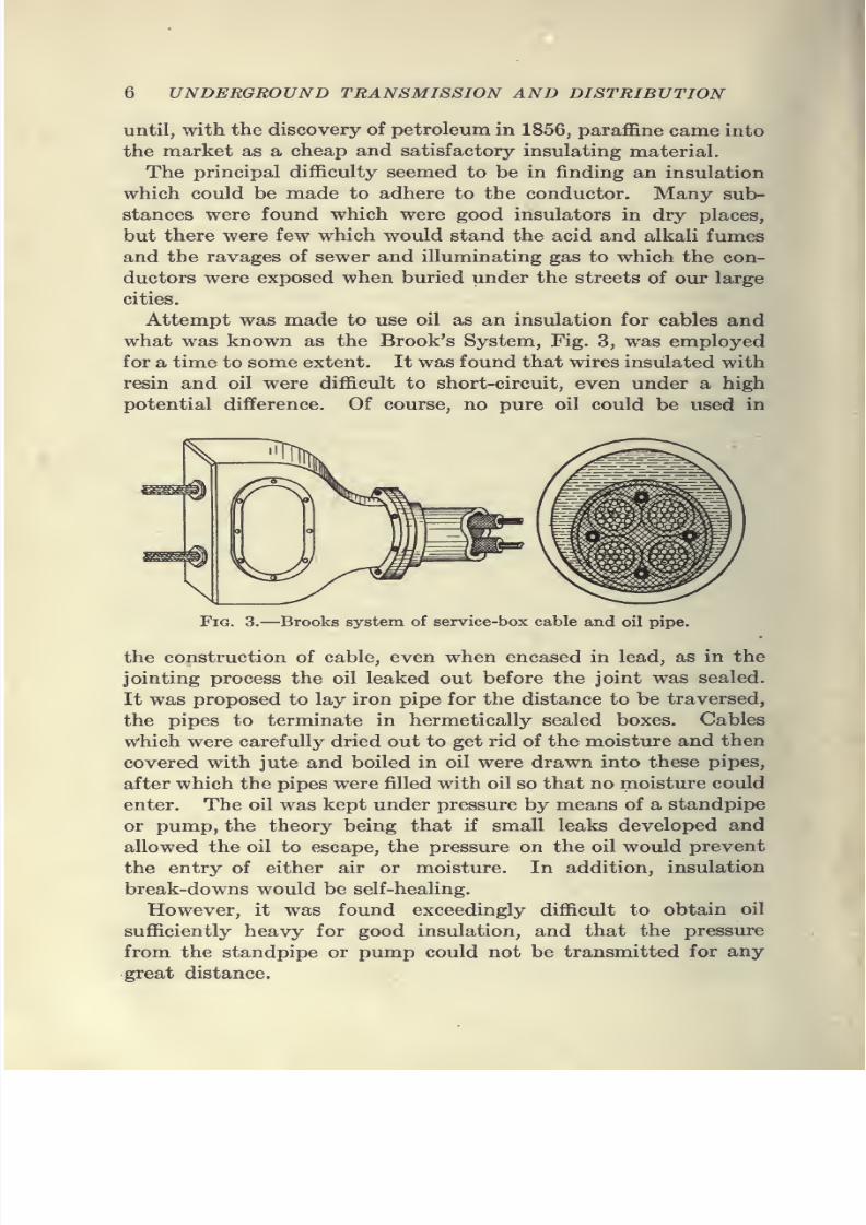
Experiments with this type of construction were made by
the Pennsylvania Railroad Co. and the Western Union Tele-
graph Co., between Newark and Jersey City, across the salt
marshes.
In England, a system was developed by Johnson and Phillips,
which gave satisfactory service. In their system the idea of
using oil under pressure was abandoned and more attention was
paid to the laying of pipes without leaks, taking especial pre-
cautions to seal the junction boxes and the pipe ends.
This system was particularly adapted for electrical lines
crossing private grounds and for long trunk lines in which therewas little probability of their being disturbed after laying.
It was very difficult, however, to keep this system in proper repair,
as leaks in the pipe line necessitated the placing of additional
junction boxes which were difficult to install without removing
the cable and refilling the entire length of the pipe. Other
disadvantages lay in the objection of workmen to handling cables
saturated with heavy oils and in difficulty in making extensions
or branch connections to the system.The failure to obtain an insulation which would stand up
under moisture and other deteriorating influences brought
about the development of the solid or built-in system.
Built-in Systems.—Numerous solid or built-in underground
systems using both insulated and bare conductors were tried as
a substitute for overhead electrical wires. The enormous expense
of making the change, as well as the utter lack of experience with
buried circuits, made this a very difficult problem from the start,
and as is usual in such cases, extraordinary methods were devised
for overcoming the difficulties.
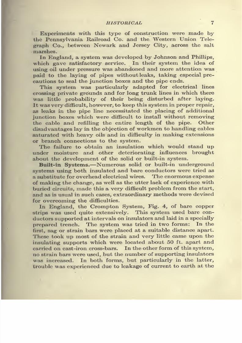
In England, the Crompton System, Fig. 4, of bare copper
strips was used quite extensively. This system used bare con-
ductors supported at intervals on insulators and laid in a specially
prepared trench. The system was tried in two forms: In the
first, sag or strain bars were placed at a suitable distance apart.
These took up most of the strain and very little came upon the
insulating supports which were located about 50 ft. apart and
carried on cast-iron cross-bars. In the other form of this system,
no strain bars were used, but the number of supporting insulators
was increased. In both forms, but particularly in the latter,
trouble was experienced due to leakage of current to earth at the
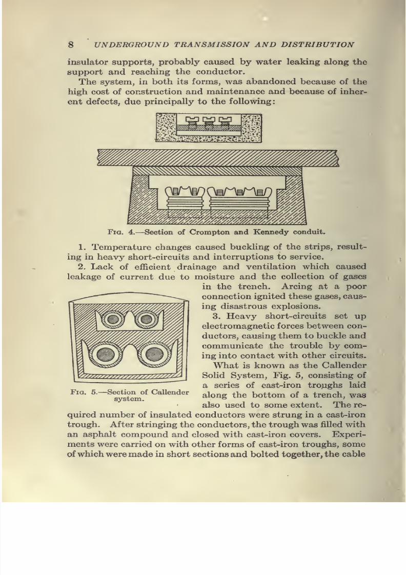
7/28/2019 Underground Trans 00 Me Yeu of t
http://slidepdf.com/reader/full/underground-trans-00-me-yeu-of-t 20/327
7/28/2019 Underground Trans 00 Me Yeu of t
http://slidepdf.com/reader/full/underground-trans-00-me-yeu-of-t 21/327
HISTORICAL 9
being placed in the troughs as laid. The troughs were usually filled
with some kind of compound to exclude moisture. These methods
of providing underground distribution, however, were- so expen-sive as to be almost prohibitive. Moreover, all systems which em-
ployed tarry or bituminous filling had two serious disadvantages.
It was difficult to keep them rigid under all conditions of tem-
perature, as at high temperatures the softening of the material
caused sagging of the system under the weight of the earth above,
resulting in damage to both the ducts and the wires which they
carried. At the low winter temperatures the conduit was likely
to crack and admit moisture. The second disadvantage lay
in the fact that in making extensions to the system it was neces-
sary to tear up the street to get at the cable on which work was to
be done.
The first objection was finally overcome by the use of iron
pipe filled with compound to give the necessary rigidity, but the
second was an inherent defect and was to a large extent respon-
sible for the final abandonment of the built-in system.
In the early eighties, the Edison Tube System of undergroundconstruction was devised and later commercially adopted by a
number of the larger cities 'in the United States and Europe.
This system consists of 20-ft. lengths of iron pipe inside which
the conductors are embedded in a bituminous compound. The
conductors, which are not removable, are usually in the shape of
round copper rod, the main tubes being designed for use on the
three-wire system. Each rod is wound with a layer of rope which
serves to keep the rods separated in case a softening of the insu-
lating material in the tubes should occur. After the rods have
been provided with the layer of rope, they are bound together
by means of a wrapping of rope and inserted in the iron pipe,
the rods projecting for a short distance at each end. The whole
tube is then filled with an insulating compound which becomes
hard when cold. The 20-ft. lengths are made in various sizes
of conductors from No. 1 gage up to 500,000 cm. for mains, and
1,000,000 cm. for feeders. Sections of the tube are designed
for use as distributing mains, and are made with three conductors
of the same size, while those designed for feeders are often made
with one conductor about half the area of the others. This
small conductor is used as the neutral for which, in a balanced
system, little capacity is required. Tubes are also provided
with potential leads to indicate at stations or substations the

7/28/2019 Underground Trans 00 Me Yeu of t
http://slidepdf.com/reader/full/underground-trans-00-me-yeu-of-t 22/327
10 UNDERGROUND TRANSMISSION AND DISTRIBUTION
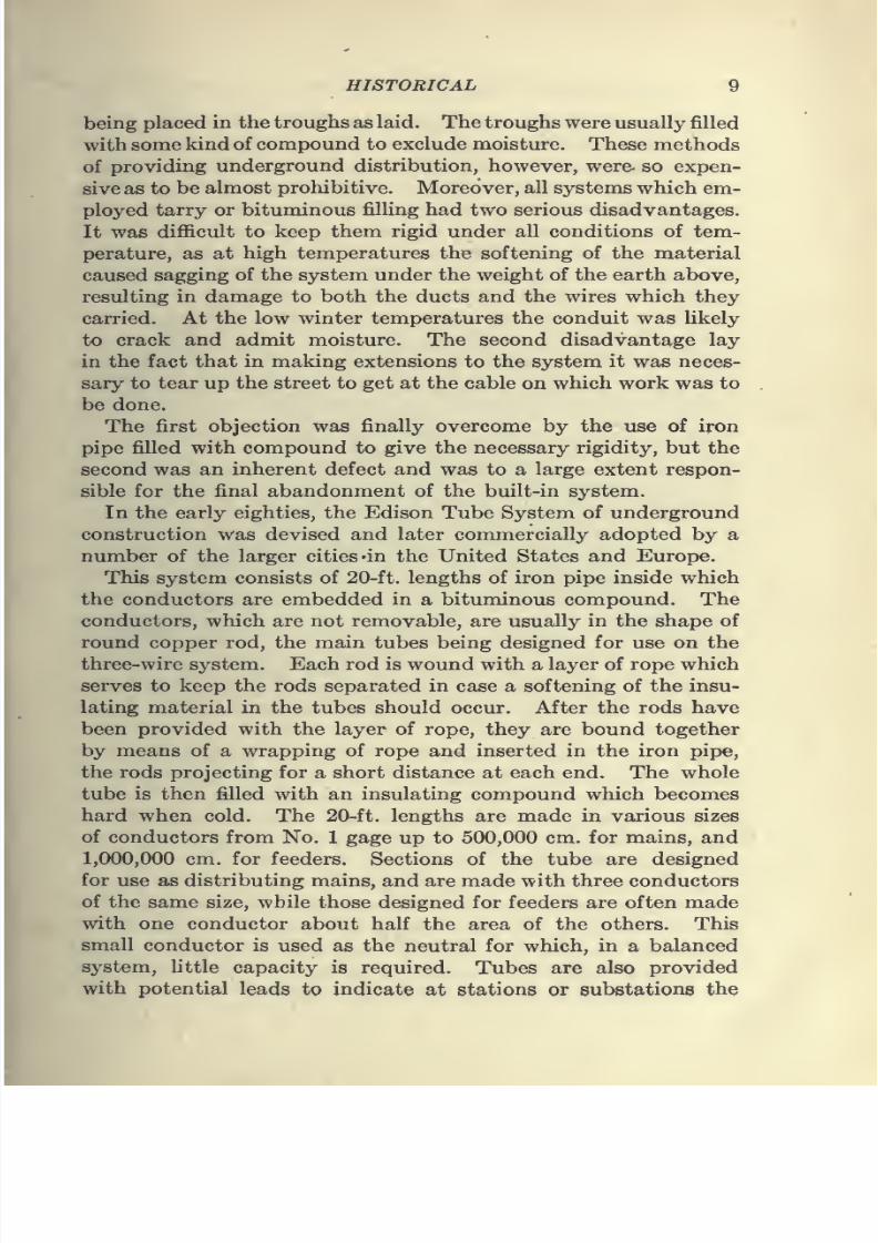
voltage at the outer end of the feeder. The tubes are laid in
the ground about 30 in. below the surface of the pavement and
are joined together by means of coupling boxes. The conductors
are connected together by means of short flexible copper cables
provided with lugs to fit over the rods and soldered in place.
The coupling boxes are made in two similar halves. After being
placed in position the two sections are securely bolted together
by means of flanged bolts. After this is done, melted compound
is poured through an opening in the upper casting and the joint
completed. Branch connections are made with T coupling boxes
Fig. 6.—Edison tube coupling joint.
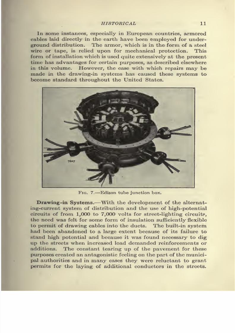
which are filled with compound in a similar manner. At centers
of distribution junction boxes are provided at which the main
feeders and the supply wires from the station join. The junc-
tion boxes are provided with fuses and water-tight covers to
allow inspection and testing. When trouble occurs, the usual
method of procedure is to dig a hole at one of the couplings and
separate the ends. By making a number of breaks in this way
at different locations, the section in which the ground or short-
circuit occurs is located and the defective length of tube replaced.
The Edison System remained standard for low-tension distribu-
tion for about 15 years, when cables drawn into ducts began to be
employed for the heavy feeders. It is still used to some extent
in cities where a large investment had been made for such work
before the development of the drawing-in system.
7/28/2019 Underground Trans 00 Me Yeu of t
http://slidepdf.com/reader/full/underground-trans-00-me-yeu-of-t 23/327
HISTORICAL 11
In some instances, especially in European countries, armored
cables laid directly in the earth have been employed for under-
ground distribution. The armor, which is in the form of a steel
wire or tape, is relied upon for mechanical protection. This
form of installation which is used quite extensively at the present
time has advantages for certain purposes, as described elsewhere
in this volume. However, the ease with which repairs may be
made in the drawing-in systems has caused these systems to
become standard throughout the United States.
Fig. 7.—Edison tube junction box.
Drawing-in Systems.—With the development of the alternat-
ing-current system of distribution and the use of high-potential
circuits of from 1,000 to 7,000 volts for street-lighting circuit?,
the need was felt for some form of insulation sufficiently flexible
to permit of drawing cables into the ducts. The built-in system
had been abandoned to a large extent because of its failure to
stand high potential and because it was found necessary to dig
up the streets when increased load demanded reinforcements or
additions. The constant tearing up of the pavement for these
purposes created an antagonistic feeling on the part of the munici-
pal authorities and in many cases they were reluctant to grant
permits for the laying of additional conductors in the streets.
7/28/2019 Underground Trans 00 Me Yeu of t
http://slidepdf.com/reader/full/underground-trans-00-me-yeu-of-t 24/327
12 UNDERGROUND TRANSMISSION AND DISTRIBUTION
In the early forms of drawing-in systems the chief difficulty
appears to have been the lack of an insulating material capable
of withstanding the high potential of arc circuits. Some troublewas also experienced on account of disintegration of the lead
sheath itself.
Lead-covered cables were being operated successfully at low
voltages, but with the undergrounding of arc-light wires failures
of the insulation soon resulted.
The difficulties which were experienced in the early days of
the drawing-in system were due not to the fact that the under-
ground system was fundamentally wrong, but rather to thefact
that in cable manufacture lack of experience prevented the intel-
dOJNT.
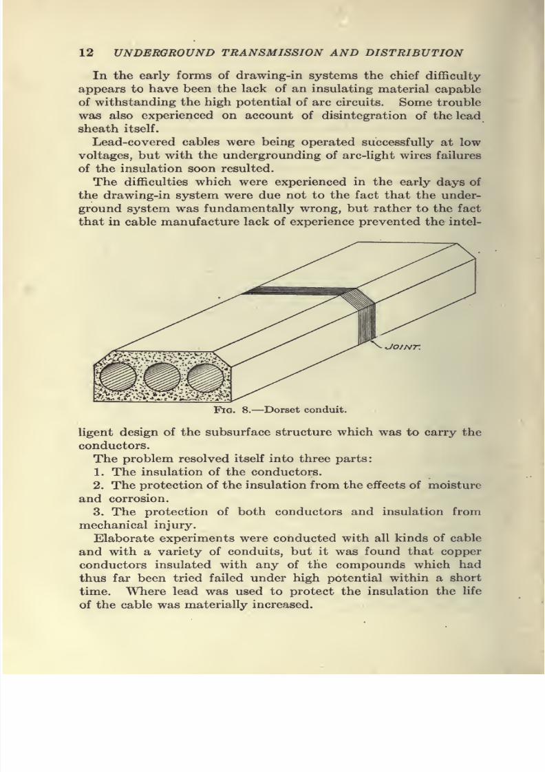
Fig. 8.—Dorset conduit
ligent design of the subsurface structure which was to carry the
conductors.
The problem resolved itself into three parts:
1. The insulation of the conductors.
2. The protection of the insulation from the effects of moisture
and corrosion.
3. The protection of both conductors and insulation from
mechanical injury.
Elaborate experiments were conducted with all kinds of cable
and with a variety of conduits, but it was found that copper
conductors insulated with any of the compounds which had
thus far been tried failed under high potential within a short
time. Where lead was used to protect the insulation the fife
of the cable was materially increased.
7/28/2019 Underground Trans 00 Me Yeu of t
http://slidepdf.com/reader/full/underground-trans-00-me-yeu-of-t 25/327
HISTORICAL 13
The Dorsett Conduit System which consisted of sections of
duct made with bituminous concrete was at one time largely
used in New York and Minneapolis and proved a complete failure
on account of the fact that it was impossible to make sure that
the compound between the ducts effected a thorough cementing
and in consequence after construction the blocks were frequently
found to have cracked apart and fallen out of alignment, thus
sacrificing all the insulating properties and reducing the cross-
section of the duct.
This type of construction was somewhat modified by General
Webber, of the British Postal Telegraph Co., and he was able
to construct a satisfactory cable-carrying conduit, but could not
make the system entirely waterproof.
In Webber's System, the 4-in. or 5-in. space between ducts
was filled with the same material of which the ducts were formed
in a molten state. This molten material melted enough of the
conduit surface to form the whole into a solid mass. The system,
however, did not permit of the use of uninsulated wires.
The system used in Minneapolis by the Interior Conduit Co.consisted of impregnated paper tubes with paper ferrules at the
joint laid in a trench. The trench was filled with a compound
composed of asphaltum and coal tar, poured while hot, entirely
covering the paper tubes. Bare copper wires were drawn into
the ducts and manholes were provided. These consisted of
double wooden boxes sealed with compound and covered with
water-tight covers. The system worked well for several years,
but was finally abandoned because of the original use of unsatisr
factory material. The paper ducts were found to be nOt abso-
lutely impervious to moisture and as the supporting wooden
blocks in time became saturated with moisture which seeped
through the paper conduits, short-circuits were frequent. The
installation was not water-tight and in many instances the whole
duct structure was filled with water after heavy rains.
The Interior Conduit Co. later used a system of paper tubes
one within the other, designed to be laid with broken joints.
The tubes were protected externally by an iron pipe or laid in
asphaltic concrete supported on blocks of earthenware. Iron
manholes were substituted for the double wooden boxes used in
the earlier systems.
Another system, known as the Cumming Duct, was used to
some extent. Four wooden ducts were enclosed in an iron pipe,
7/28/2019 Underground Trans 00 Me Yeu of t
http://slidepdf.com/reader/full/underground-trans-00-me-yeu-of-t 26/327
7/28/2019 Underground Trans 00 Me Yeu of t
http://slidepdf.com/reader/full/underground-trans-00-me-yeu-of-t 27/327
7/28/2019 Underground Trans 00 Me Yeu of t
http://slidepdf.com/reader/full/underground-trans-00-me-yeu-of-t 28/327
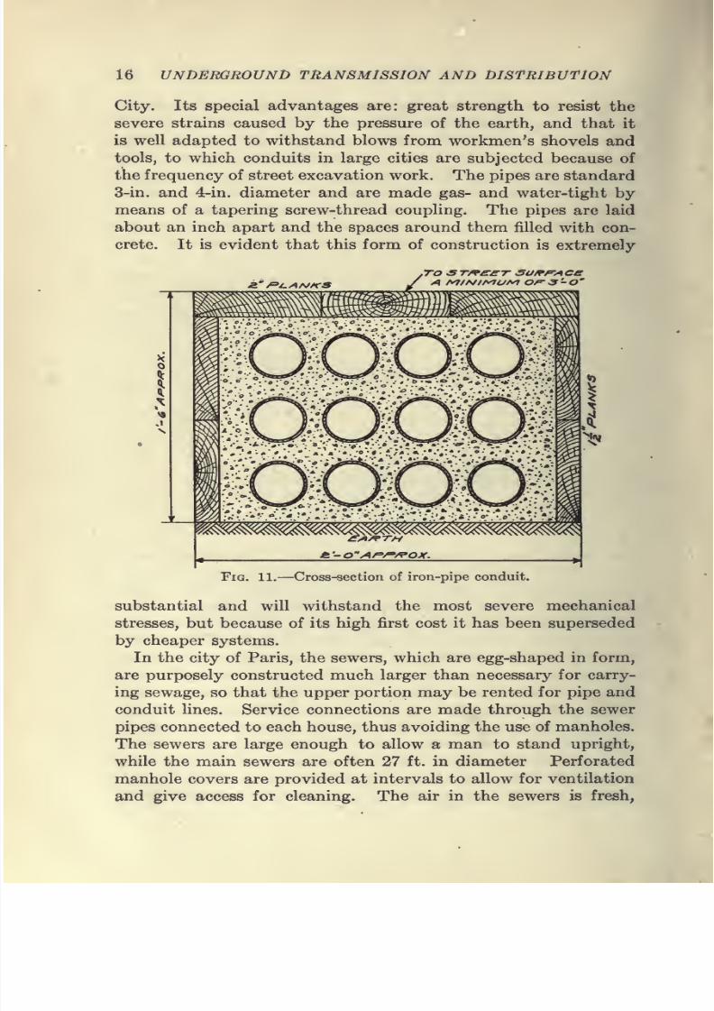
16 UNDERGROUND TRANSMISSION AND DISTRIBUTION
City. Its special advantages are: great strength to resist the
severe strains caused by the pressure of the earth, and that it
is well adapted to withstand blows from workmen's shovels andtools, to which conduits in large cities are subjected because of
the frequency of street excavation work. The pipes are standard
3-in. and 4-in. diameter and are made gas- and water-tight by
means of a tapering screw-thread coupling. The pipes are laid
about an inch apart and the spaces around them filled with con-
crete. It is evident that this form of construction is extremely
JZ f=>l.AS/KS
To £T^££T- SUfPf'ACe
TAi/^TH
\
Fig. 11.—Cross-section of iron-pipe conduit.
substantial and will withstand the most severe mechanical
stresses, but because of its high first cost it has been superseded
by cheaper systems.
In the city of Paris, the sewers, which are egg-shaped in form,
are purposely constructed much larger than necessary for carry-
ing sewage, so that the upper portion may be rented for pipe and
conduit lines. Service connections are made through the sewer
pipes connected to each house, thus avoiding the use of manholes.
The sewers are large enough to allow a man to stand upright,
while the main sewers are often 27 ft. in diameter Perforated
manhole covers are provided at intervals to allow for ventilation
and give access for cleaning. The air in the sewers is fresh,
7/28/2019 Underground Trans 00 Me Yeu of t
http://slidepdf.com/reader/full/underground-trans-00-me-yeu-of-t 29/327
7/28/2019 Underground Trans 00 Me Yeu of t
http://slidepdf.com/reader/full/underground-trans-00-me-yeu-of-t 30/327
18 UNDERGROUND TRANSMISSION AND DISTRIBUTION
of the entire investment, and for the reason that these structures
are themselves as important as any Unk in the chain of central-
station equipment, and because of the relatively large investment
involved, great care should be exercised in determining the kind
and type of underground construction to be used. In the suc-
ceeding chapters the types of construction which are in use to-day
are described in detail, together with specifications, costs, and
other data to be used as a guide for the central-station engineer
in the design and operation of underground systems of trans-
mission and distribution.
7/28/2019 Underground Trans 00 Me Yeu of t
http://slidepdf.com/reader/full/underground-trans-00-me-yeu-of-t 31/327
CHAPTER II
PRELIMINARY SURVEY
Planning the System.—In planning a conduit system for
general use in housing both transmission and distribution feeders,
as well as mains and service cable, the first thing to be decided
upon is the method of distribution. The systein of distribution
depends to a large extent upon local conditions and in many cases
will follow the general plan of the existing overhead system, except
in large cities where obstructions in the streets and the expense
of approved paving methods will frequently determine to a great
extent the route to be followed.
In some cities, local ordinances prescribe the use of poles in
alleys for block distribution, and in such cases the conduits are
usually laid on the main streets or thoroughfares. Where the use
of overhead alley distribution is permissible, the problem of
eliminating pole lines from the streets is relatively easy and the
cost of underground construction is materially reduced.
Maps.—When the method of distribution has been decided
upon and the streets on which the ducts are to be laid have been
determined, a map should be prepared showing the location and
size of the proposed duct line.
The problems presented to the engineer who is responsible
for the installation of an underground system are many, but he
has a comparatively large field from which to choose methods and
materials. Local conditions will determine to a large extent the
character of the construction to be employed. Conduit systems
are usually laid subsequent to other subsurface structures such
as water and sewer pipes and gas mains, and it is therefore neces-
sary in preparing specifications and estimates that locations of
existing subsurface structures be known in advance as definitely
as possible. The engineer should, therefore, provide himself
with a map of the district to be covered in order that he maydetermine what streets can best be used after considering the load
on the system and determining the method of distribution. Maps
or surveys should be drawn to scale in order that the locations
of foreign structures may be plotted thereon.
19
7/28/2019 Underground Trans 00 Me Yeu of t
http://slidepdf.com/reader/full/underground-trans-00-me-yeu-of-t 32/327
20 UNDERGROUND TRANSMISSION AND DISTRIBUTION
A record of the subsurface structures can generally be obtained
by applying to the municipal authorities. While this informa-
tion will frequently be found of great value in making a pre-
liminary layout, too much dependence should not be placed
thereon, as such records are not always accurate and are quite
often incomplete.
It is, therefore, necessary to checkup these records in the streets
where underground structures are numerous, particularly in
cases where the space available for a conduit installation is limited
by such structures.
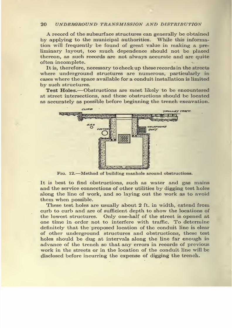
Test Holes.—Obstructions are most likely to be encounteredat street intersections, and these obstructions should be located
as accurately as possible before beginning the trench excavation.
TJWox-t*-/ Tn/tCH.
Fia. 12.—Method of building manhole aroxmd obstructions.
It is best to find obstructions, such as water and gas mainsand the service connections of other utilities by digging test holes
along the line of work, and so laying out the work as to avoid
them when possible.
These test holes are usually about 2 ft. in width, extend from
curb to curb and are of sufficient depth to show the locations of
the lowest structures. Only one-half of the street is opened at
one time in order not to interfere with traffic. To determine
definitely that the proposed location of the conduit line is clear
of other underground structures and obstructions, these test
holes should be dug at intervals along the line far enough in
advance of the trench so that any errors in records of previous
work in the streets or in the location of the conduit line will be
disclosed before incurring the expense of digging the trench.

7/28/2019 Underground Trans 00 Me Yeu of t
http://slidepdf.com/reader/full/underground-trans-00-me-yeu-of-t 33/327
PRELIMINARY SURVEY 21
Where possible, test holes should be dug at the proposed man-
hole sites with the double purpose of utilizing the extra excava-
tion and of obtaining definite information as to the availability
of the proposed manhole location.
,Curb
j^/Gaa
c
^Water
''!S'.-.'-'A-'.v.c:t-. -^q.-'''&'•'.: .tV'-'.'.'/iy.-'.'tr"
/Telephone Conduit
I j I I
C.l|.o^ Trolley Rail I iy fiail
Fig. 13.—Street main cut around Aianhole.
I I
I I
H y-
^£Tf^££T SU/^/=-/\C£
w*^TeK sr^^Kc ^i^K.
lb
C/^OSS SscT/orsf
Fig. 14.—Method of building conduit around service pipes.
It is frequently found after measurements are taken in the test
holes, that while there is sufficient space for the conduit, the space
7/28/2019 Underground Trans 00 Me Yeu of t
http://slidepdf.com/reader/full/underground-trans-00-me-yeu-of-t 34/327
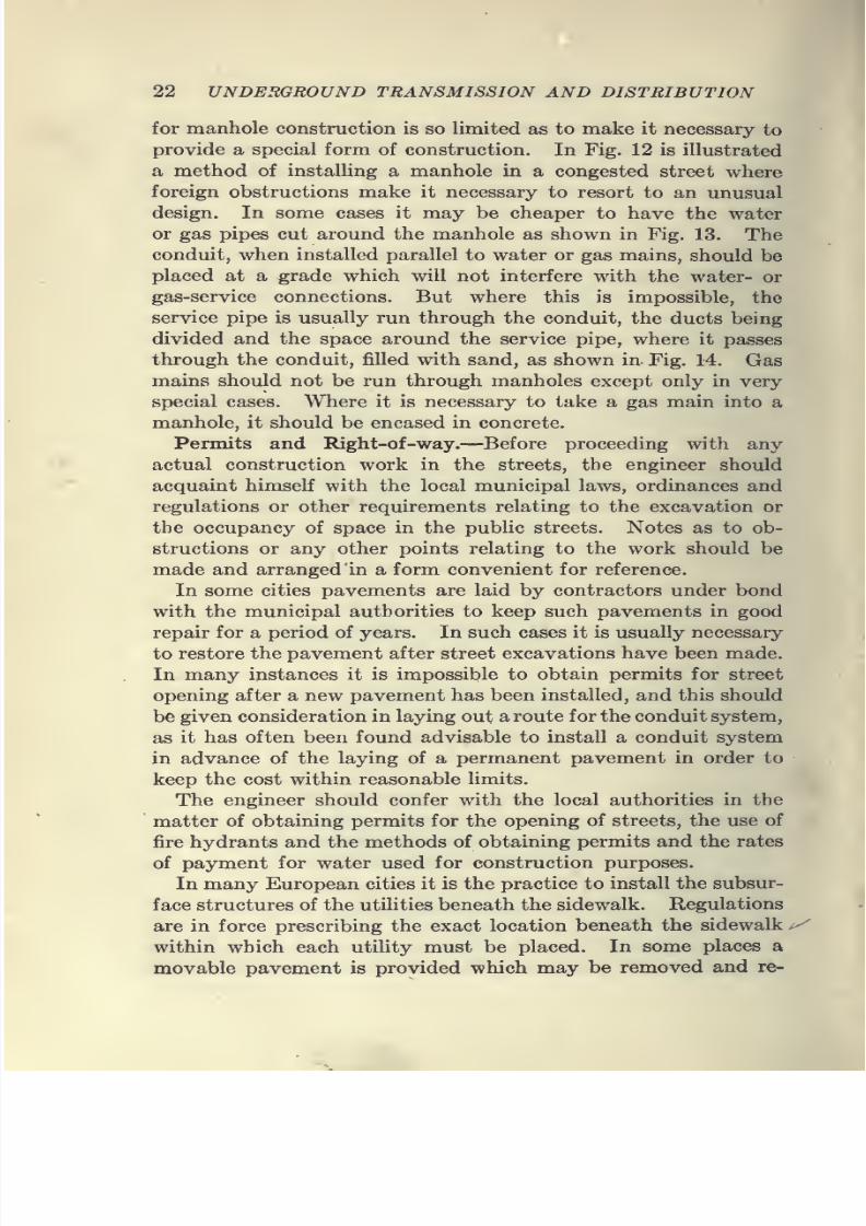
22 UNDERGROUND TRANSMISSION AND DISTRIBUTION
for manhole construction is so limited as to make it necessary to
provide a special form of construction. In Fig. 12 is illustrated
a method of instalUng a manhole in a congested street where
foreign obstructions make it necessary to resort to an unusual
design. In some cases it may be cheaper to have the water
or gas pipes cut around the manhole as shown in Fig. 13. The
conduit, when installed parallel to water or gas mains, should be
placed at a grade which will not interfere with the water- or
gas-service connections. But where this is impossible, the
service pipe is usually run through the conduit, the ducts being
divided and the space around the service pipe, where it passes
through the conduit, filled with sand, as shown in- Fig. 14. Gas
mains should not be run through manholes except only in very
special cases. Where it is necessary to take a gas main into a
manhole, it should be encased in concrete.
Permits and Right-of-way.—^Before proceeding with any
actual construction work in the streets, the engineer should
acquaint himself with the local municipal laws, ordinances and
regulations or other requirements relating to the excavation orthe occupancy of space in the public streets. Notes as to ob-
structions or any other points relating to the work should be
made and arranged in a form convenient for reference.
In some cities pavements are laid by contractors under bond
with the municipal authorities to keep such pavements in good
repair for a period of years. In such cases it is usually necessary
to restore the pavement after street excavations have been made.
In many instances it is impossible to obtain permits for street
opening after a new pavement has been installed, and this should
be given consideration in laying out a route for the conduit system,
as it has often been found advisable to install a conduit system
in advance of the laying of a permanent pavement in order to
keep the cost within reasonable limits.
The engineer should confer with the local authorities in the
matter of obtaining permits for the opening of streets, the use of
fire hydrants and the methods of obtaining permits and the rates
of payment for water used for construction purposes.
In many European cities it is the practice to install the subsur-
face structures of the utilities beneath the sidewalk. Regulations
are in force prescribing the exact location beneath the sidewalk
within which each utility must be placed. In some places a
movable pavement is provided which may be removed and re-
7/28/2019 Underground Trans 00 Me Yeu of t
http://slidepdf.com/reader/full/underground-trans-00-me-yeu-of-t 35/327
PRELIMINARY SURVEY 23
placed without great expense, allowing repairs to be made to the
subsurface structures. The advantages of locating utilities be-
neath the sidewalks as compared with their placement beneaththe street pavement are that it is less expensive to remove a
cheap sidewalk than a costly pavement, and the maintenance
cost is lowered. Structures placed under the sidewalk are not
subjected to the shock and vibration from heavy overhead
traffic, and the installation of transportation subways is made
considerably less expensive where no underground utilities have
to be maintained in service during construction.
In someof the larger cities in
the UnitedStates,
the streetshave become so congested with both surface and subsurface
structures that the matter of subsurface construction has been
placed under the control of a Municipal Board consisting of the
Chiefs of Bureaus of Highways, Surveys, City Property, Electri-
cal Bureaus, etc., the idea being to have all departments concerned
with surface or subsurface construction of streets represented
on the Board. One of the most important duties of this Board
is the obtaining, compiling and mapping of all possible informa-
tion concerning existing or projected structures under streets.
For carrying out the work, a corps of field inspectors and drafts-
men is maintained, and necessary authority and power given the
Board to enable it to obtain the required information and to con-
trol the action of both corporations and individuals in their
use of the streets.
In some cities it is required that plans showing all existing
underground structures be filed in duplicate together with com-
plete details of proposed construction. All work and material
used must be satisfactory to the Chief of the Electrical Bureau
and any work and material condemned must be at once replaced
in acceptable form. After work is completed, the party to whom
the permit is issued is required to file complete plans in detail
showing the work as constructed, with all previously existing
structures encountered during the construction work.
The foregoing applies to only a few cases where subsurface
structures and transportation subways occupy practically all
of the available space under the street surface.
When electrical companies are required to remove overhead
wir^s and poles from streets or public highways, it is the usual
practice to confer with the authorities and arrange for some satis-
factory manner of procedure. While franchise requirements will
/
7/28/2019 Underground Trans 00 Me Yeu of t
http://slidepdf.com/reader/full/underground-trans-00-me-yeu-of-t 36/327
24 UNDERGROUND TRANSMISSION AND DISTRIBUTION
govern the form of the agreement in any particular case, the
following is submitted as a specimen:
FORM OF AGREEMENT
AN ORDINANCE granting permission to (name of company), its suc-
cessors and assigns, to lay and maintain underground conduits, cables,
wires and manholes for electrical conductors in the streets, avenues and pub-
lic places of the city (or town) of for the use and purposes of its
business, and providing for the removal of certain overhead wires and pole
lines.
BE IT ORDAINED by the Common Council of the city (or town) of
as follows:
Section I.—That (name of company), its successors and assigns, be and
it is hereby authorized and empowered to construct and maintain for the
use and purposes of its business, a system of subways and underground con-
duits, laterals, service conduits, service boxes and manholes beneath the
surface of the streets, avenues, and other public places of the city (or town)
of as the boundaries thereof arenow ormay hereafter be, and to place,
maintain and operate therein wires, cables and other electrical conductors
necessary for such purposes; provided that said subway shall be confined
within a space of four (4) feet in width, except the manholes, which may be
constructed of the usual size and shape necessary or advantageous for the
conduct of the business of said company.
Section II.—That (name of company) shall, within six (6) months after
the passage and acceptance of this ordinance, proceed to construct its sub-
ways or underground conduits with the necessary laterals, service conduits,
service boxes, manholes and street openings "in (state requirements of first
year's work, giving names of streets and avenues in which conduits are to
be installed). After the completion of the subways or underground conduits
in the above-mentioned streets, said (name of company) may extend its
conduits and subways through the other streets, avenues, and public placesof the city (or town) of from time to time, as the requirements of its
business shall demand.
Section III.—That within one year from the laying of subways or con-
duits in any street, avenue or public place in the city (or town) of or
any section thereof, said company shall remove its electrical conductors,
poles and fixtures from above the surface of those sections of said streets,
avenues or public places beneath which said subways or conduits shall be
constructed, except where said poles and fixtures are used for supporting
public lights, or for the purpose of supporting or connecting with wires in
intersecting streets, and thereupon the right of said company to maintain the
poles so required to be removed shall cease and become void; and the said
company shall repair the sidewalks from which said poles shall have been
removed.
Section IV.—That the said (name of company) before opening any street
for the doing of any part of the work hereby authorized, shall from time to
time file in the office of the city (or town) of a map or plan showing
7/28/2019 Underground Trans 00 Me Yeu of t
http://slidepdf.com/reader/full/underground-trans-00-me-yeu-of-t 37/327
7/28/2019 Underground Trans 00 Me Yeu of t
http://slidepdf.com/reader/full/underground-trans-00-me-yeu-of-t 38/327
26 UNDERGROUND TRANSMISSION AND DISTRIBUTION
The cost of restoring the earth or otherwise and the cost of replacing the
pavement and repairs thereto, caused by the opening of any such street
or avenue, shall be paid for by said company, and the said company shall
likewise pay the cost of an inspector appointed by the city (or town) of
to supervise the work. The expense of such supervision and the cost
of such inspector shall be paid by said company upon the presentation of
bills therefor, certified by the proper officer of the city (or town) and the
expense to which the city (or town) of shall be put from the neglect
of said company, or its employees or the doing of any work in an unwork-
manlike manner in the digging of trenches or holes, or in the restoring of
the earth, or of the relaying or replacing of any pavement, shall in like
manner be paid by said company. In case the work or any part thereof
shall not be done to the satisfaction of the city (or town) engineer, or the
person appointed by him having the supervision of streets and highways,
the said city (or town) engineer may, without waiving any of its rights
hereunder, cause the said work to be performed or material to be supplied
to its satisfaction; and the company agrees upon the presentation of bills
therefor, certified by the proper officer in the city (or town) to pay at once
the same, including the cost of both inspection and of labor and material;
provided, however, that before any work shall be done or material supplied
by the city (or town) of for the cost of which (name of company)
under this section shall be liable, the city (or town) engineer shall give
notice in writing to (name of company) of the work required to be done andthe material required to be supplied, and the company shall have ten (10)
days within which to begin the work and supply material by such notice
required to be done or provided, and shall have a reasonable time thereafter
within which to complete the said work.
Section V.—The said company shall indemnify and save harmless the
city (or town) of , its officers, servants and agents, against all loss,
and shall assume all liability and pay all damages which may at any time
arise, come or occur to the city (or town) of ,its officers or agents, from
any injury to person or property, from the doing of any work hereinbefore
mentioned, or from the doing of said work negligently or unskillfuUy,
or from the neglect of said company or its employees to comply with the
provisions of any ordinance of the city (or town) of relative to the
use of the streets, or from the failure to put up proper lights and barriers at
or around excavations, or from the failure to support properly the tracks of
steam railroads or street railways during the prosecution of the work and
thereafter, and the acceptance by the company of this ordinance shall be
an agreement by said company to pay the city (or town) of on any
sum of money for which the city (or town) of may become liable
from or by reason of any injury or damage.
Section VI.—The said company shall file with the city (or town) of
its acceptance of this ordinance within thirty (30) days from the date on
which it shall take effect.
Section VII.—That the company shall repay the city (or town) of
the amount of the cost and expense to the city (or town) of
of all oflBcial publication of this ordinance.
Section VIII.—That this ordinance shall take effect immediately.
7/28/2019 Underground Trans 00 Me Yeu of t
http://slidepdf.com/reader/full/underground-trans-00-me-yeu-of-t 39/327
PRELIMINARY SURVEY 27
Other forms of agreement provide for the removal of overhead
wires and poles in certain definitely prescribed sections of the city
or town, covering a period of from 5 to 20 years. In such casesthe operating company has the advantages of being in a position
to lay out definitely its work from year to year, and to make
plans for the entire system, thus providing at the very start for
the ultimate number and size of conduit and manholes.
Still other forms of agreement provide for the expenditure of
a certain sum ranging from $5,000 to $50,000, depending on
the size of the city and the financial condition of the operating
company.
Some companies have agreed to construct each year a certain
number of lineal feet of underground conduit, the municipality
exercising the right to designate the streets in which it desires
to have conduit installed, covering not more than one-half of
the total amount, the remainder being left to the judgment of
the company. The streets designated by the city (or town) must
be contiguous to the present subway system. The forms of
agreement regarding the amount of work to be done are de-
pendent entirely on local conditions, and the foregoing outline is
given merely to aid the engineer in determining a proper method
of procedure.
Regulations.—Many states have enacted laws to regulate the
construction and maintenance of subway systems, with a view to
safeguarding workmen.
In some cases these laws fix the size of manholes so as to pro-
vide sufficient working space for the necessary jointing and
repairs, and the size and location of manhole covers. The
proposed National Electrical Safety Code, in the prehminary
edition issued by the Bureau of Standards, April 29, 1915, con-
tains the following recommendations covering manholes, hand-
holes and ducts:
Location
Underground systems of electrical conductors should be so located as to
be subject to the least practicable amount of disturbance. When beingdesigned and installed, care should be exercised to avoid catchment basins,
street railway tracks, gas pipes, or other underground structures which
have been installed or are planned for the future.
To facilitate installing and withdrawing cables and conductors, the
ducts between adjacent manholes or other outlets should be installed in
straight lines, except when it is necessary to install curves, in which case
7/28/2019 Underground Trans 00 Me Yeu of t
http://slidepdf.com/reader/full/underground-trans-00-me-yeu-of-t 40/327
28 UNDERGROUND TRANSMISSION AND DISTRIBUTION
they should be of not less than 25 ft. radius, and manholes or other outlets
spaced closer together than on straight runs.
Grading
Manholes should be so located and ducts so graded that drainage of
ducts will always be toward manholes or handholes. To insure satisfactory
drainage, the ducts should be so installed as to provide a grade of not less
than 3 in. in 100 ft. of length.
Accessibility
Manholes should be so located as to provide safe and ready access, and,
if possible, so that the least horizontal distance from any rail of a railroad
track to the nearest edge of a manhole opening is not less than 3 ft.
Mechanical Details
The mechanical design and construction of manholes and handholes shall
be such as to provide sufficient strength to safely sustain the mechanical
loads which will be imposed upon them.
The entrance to all manholes shall be not less than 24 in. minimum
diameter. Round openings are recommended.
Manholes should be so constructed when practicable that the least
inside dimension will be not less than 3 ft. 6 in., and should be so arranged
as ta maintain a clear working space whose least dimensions are not less
than 3 ft. horizontally and 6 ft. vertically, except that where the opening is
within 1 ft. on each side of the full size of the manhole the depth may be less.
Where conditions will permit, a larger working space than the above should
be provided.
Manholes and handholes shall be so arranged, if practicable, as to provide
permanent drainage through trapped sewer connections or otherwise for
such surface or drainage water as may flow into them.
Manhole Covers
Manholes and handholes while not being worked in shall be securely
closed by covers of sufficient strength to sustain such mechanical loads as
will be imposed upon them, and so secured in place that a tool or appliance
is required for their opening or removal.
Mechanical Barriers and Guards
Manhole openings shall be so arranged that they may, when uncovered,
be surrounded by substantial metal barrier guards.
Material, Size, and Finish, op Ducts
Ducts used in underground systems of distribution for electrical supply
and signal conductors shall be of such material, size, mechanical strength,
and finish as to permit the safe installation and maintenance of all con-
ductors or cables to be maintained in them.
7/28/2019 Underground Trans 00 Me Yeu of t
http://slidepdf.com/reader/full/underground-trans-00-me-yeu-of-t 41/327
PRELIMINARY SURVEY 29
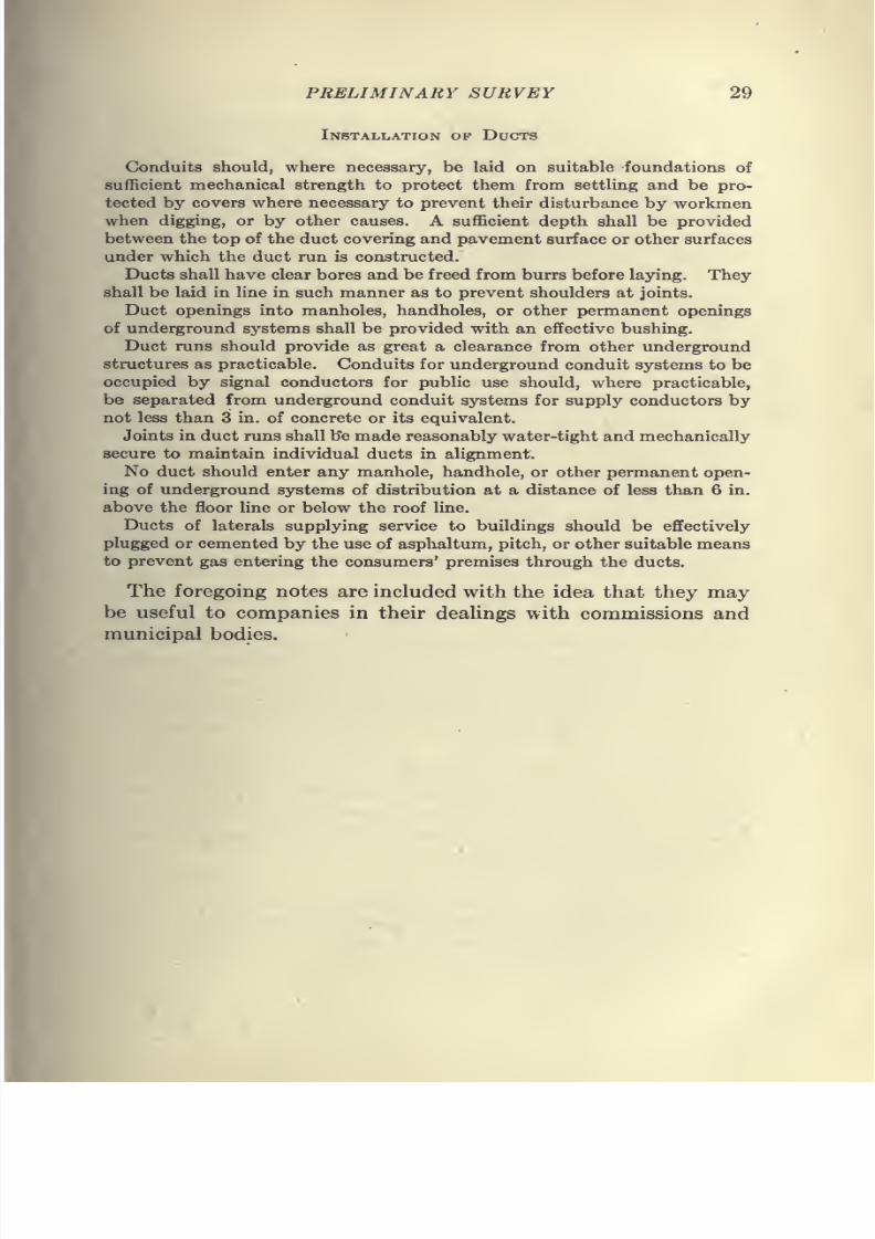
Installation of Ducts
Conduits should, where necessary, be laid on suitable foundations ofsufficient mechanical strength to protect them from settling and be pro-
tected by covers where necessary to prevent their disturbance by workmen
when digging, or by other causes. A sufficient depth shall be provided
between the top of the duct covering and pavement surface or other surfaces
under which the duct run is constructed.
Ducts shall have clear bores and be freed from burrs before laying. They
shall be laid in line in such manner as to prevent shoulders at joints.
Duct openings into manholes, handholes, or other permanent openings
of underground systems shall be provided with an effective bushing.
Duct runs should provide as great a clearance from other underground
structures as practicable. Conduits for underground conduit systems to be
occupied by signal conductors for public use should, where practicable,
be separated from underground conduit systems for supply conductors by
not less than 3 in. of concrete or its equivalent.
Joints in duct runs shall b"e made reasonably water-tight and mechanically
secure to maintain individual ducts in alignment.
No duct should enter any manhole, handhole, or other permanent open-
ing of underground systems of distribution at a distance of less than 6 in.
above the floor line or below the roof line.
Ducts of laterals supplying service to buildings should be effectively
plugged or cemented by the use of asphaltum, pitch, or other suitable means
to prevent gas entering the consumers' premises through the ducts.
The foregoing notes are included with the idea that they may-
be useful to companies in their deaUngs with commissions and
municipal bodies.
7/28/2019 Underground Trans 00 Me Yeu of t
http://slidepdf.com/reader/full/underground-trans-00-me-yeu-of-t 42/327
CHAPTER III
CONDUIT AND MANHOLE CONSTRUCTION
Selection of Materials.—"Whether it is the intention of the
central-station engineer to build the conduit line himself, or to
have it built by contract, there will be certain material and labor
used, and these should be the best of their kind in either case."*
Having decided on the routes of the conduit, the type of conduit
line to be constructed should be determined.
A few years ago a 3-in. diameter duct was considered suffi-
ciently large, but for feeder cables called for today, which are
often over 3 in. in diameter, nothing less than a 33^-in. bore
conduit should be used.
If the material selected is of the best, and the workmanship
all that it should be, there is no reason why a first-class conduit
should not last indefinitely and the repair and maintenance
charges be low.
Installation of Conduit.—In the laying of conduit, trenches
should be dug to a line stretched along the street to keep the
ditch straight, and the width should be kept constant by means
of a stick cut to the required length and used as a gage. The
ditch should be dug in the rough, somewhat narrower than the
finished width, the exact width being obtained by trimming.
This method produces a straight smooth finish on the sides of the
trench and will aid materially in keeping the ducts straight and
also in reducing the quantity of concrete required for any given
duct section.
The bottom of the trench should be carefully leveled and
graded to the required depth and grade stakes should be driven
at intervals throughout the length of the ditch for the purpose of
limiting the thickness of the concrete base and of fixing the exact
grade of the finished conduit.Ducts should be so laid as to drain toward manholes, for if
pockets are formed and the duct Une is submerged it is likely
to freeze in winter weather and injure the insulation of the cable,
and possibly, damage the conduit.
1 Hancock, N. E. L. A., 1904.
30
7/28/2019 Underground Trans 00 Me Yeu of t
http://slidepdf.com/reader/full/underground-trans-00-me-yeu-of-t 43/327
CONDUIT AND MANHOLE CONSTRUCTION 31
In the laying of conduit great care should be taken to insure
that the alignment of the ducts is not disturbed previous to or
during, the process of filling in the space between the ducts andsides of the trench, or in placing the top cover on the concrete.
In digging the trench, paving materials or old concrete should
be carefully separated from the earth and all excavated material
should be thrown well back from the brows of the ditch to pro-
vide wheeling space for concrete and other materials, in order to
prevent them from being brushed into the ditch by workmen.
Where deep ditches are required, and the soil is of an unstable
character, shoring or bracing will be necessary. This is especiallynecessary in case of severe rains during the progress of the work,
and the force engaged in the work should always be so arranged
that the smallest possible amount of trench consistent with
economical working, will be opened at one time.
In many cities there is a limit set on the amount of street which
may be opened at one time.
Where it is the intention of the engineer to furnish his own
laborand
material inthe
construction ofthe conduit
line, it is
essential that he provide himself with a general foreman, or
general superintendent, who is thoroughly familiar with the
laying out of the work, handling the men and attending to the
details of city-street construction. It will be necessary to place
considerable confidence in this man and his ability should be
such that the payroll will be reduced to a minimum and the
amount of work completed each day be consistent with the
number of men employed.
The superintendent of construction should be familiar with
all of the details of the work, and see that his assistant properly
protects the life and property of others observing the city
regulations and providing bridges over openings at intersecting
streets. Proper barriers should be placed where required, and
excavations should be flagged at all times, to avoid accidents to
pedestrians, or interference with traffic. The trench should be
properly patroled at night by a watchman, whose duty it should
be to see that the lanterns are kept lighted throughout the
night.
It is important that records be made of the progress of each
day's work and that measurements be taken showing the actual
location of the work, foreign conduits, pipes, and any other ob-
7/28/2019 Underground Trans 00 Me Yeu of t
http://slidepdf.com/reader/full/underground-trans-00-me-yeu-of-t 44/327
7/28/2019 Underground Trans 00 Me Yeu of t
http://slidepdf.com/reader/full/underground-trans-00-me-yeu-of-t 45/327
CONDUIT AND MANHOLE CONSTRUCTION 33
Concrete for conduit work should be mixed from good Port-
land cement and clean sand and gravel, or broken stone, in the
proportions of 1 part cement to 3 parts of sand and 5 parts ofgravel or broken stone, with sufficient water to thoroughly wet
the mix, and allow a small amount of water to come to the surface
when the concrete is ready for pouring.
Most brands of Portland cement manufactured at the present
time appear to be satisfactory and will pass the strength tests
if the cement is a representative sample of the manufacturer's
output.
It is
customary totest
cement for tensile strength, the reasonbeing that concrete is weaker in tension than compression.
Specifications for cement may be obtained from any of the
members of the Association of Portland Cement Manufacturers,
and they will, therefore, not be printed here. It is customary to
test samples of cement from each shipment received, some engi-
neers testing one sample from each 8 or 10 bbl. received, others
testing only one sample from each carload. The number of
samples to be tested depends on the importance of the work,
but in ordinary conduit work and manhole construction one test
from each carload should be sufficient.
There are several important considerations to be observed in
the selection of aggregates for concrete. The material entering
into the concrete must be of such structure and quality as to suit
the use to which the concrete is to be put. Aggregates should
remain in an unaltered physical state as long as the concrete lasts
and should be so graded as to give a maximum density, strength
and impermeability. The material selected should show a definite
strength in combination with the cement.
The matter of using a good quality of sand is very important.
All sands are derived from the decomposition of natural rock of
various kinds. It is frequently stated in specifications that clean
sharp sand must be used, and while this is important, it is more
important that sand be properly graded so as to secure a dense
mass. Sand containing loam or clay should not be used, for if
it has been properly washed all such foreign materials will have
been removed.
When mixed by hand, the cement, sand and stone should
be turned at least three times dry and twice wet, and the concrete
should be- placed immediately after mixing. When all the con-
crete has been placed in the trench, it should be allowed to take
8
7/28/2019 Underground Trans 00 Me Yeu of t
http://slidepdf.com/reader/full/underground-trans-00-me-yeu-of-t 46/327
34 UNDERGROUND TRANSMISSION AND DISTRIBUTION
its initial set before the trench is filled in and tamped, and the
pavement replaced in order to avoid throwing the conduit out
of line or fracturing the concrete while it is still weak.
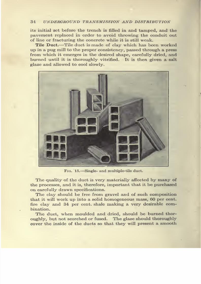
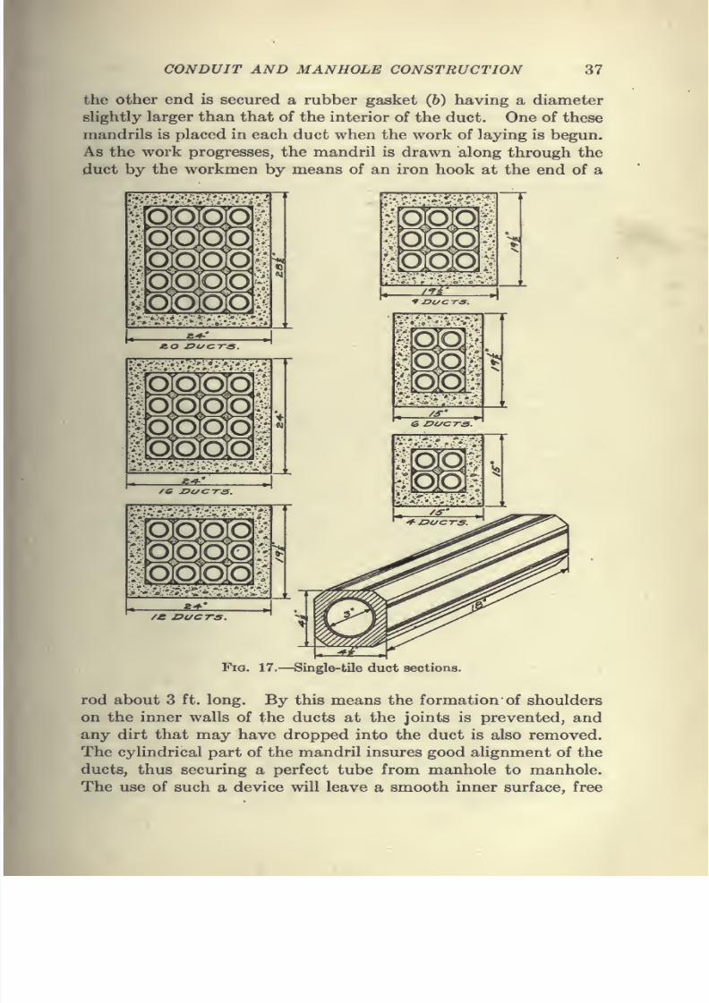
Tile Duct.—Tile duct is made of clay which has been worked
up in a pug mill to the proper consistency, passed through a press
from which it emerges in the desired shape, carefully dried, and
burned until it is thoroughly vitrified. It is then given a salt
glaze and allowed to cool slowly.
Fig. 15.—Single- and multiple-tile duct.
The quality of the duct is very materially affected by many of
the processes, and it is, therefore, important that it be purchased
on carefully drawn specifications.
The clay should be free from gravel and of such composition
that it will work up into a solid homogeneous mass, 60 per cent,
fire clay and 34 per cent, shale making a very desirable com-
bination.
The duct, when moulded and dried, should be burned thor-
oughly, but not scorched or fused. The glaze should thoroughly
cover the inside of the ducts so that they will present a smooth
7/28/2019 Underground Trans 00 Me Yeu of t
http://slidepdf.com/reader/full/underground-trans-00-me-yeu-of-t 47/327
CONDUIT AND MANHOLE CONSTRUCTION 35
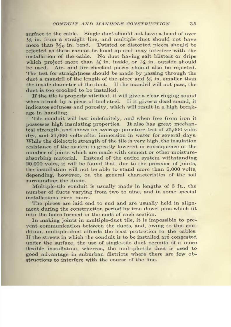
surface to the cable. Single duct should not have a bend of over
% in. from a straight line, and multiple duct should not have
more than ^q in. bend. Twisted or distorted pieces should be
rejected as these cannot be lined up and may interfere with the
installation of the cable. No duct having salt blisters or drips
which project more than ^ in. inside, or ^ in. outside should
be used. Air- and fire-checked pieces should also be rejected.
The test for straightness should be made by passing through the
duct a mandril of the length of the piece and }^ in. smaller than
the inside diameter of the duct. If the mandril will not pass, the
duct is too crooked to be installed.
If the tile is properly vitrified, it will give a clear ringing sound
when struck by a piece of tool steel. If it gives a dead sound, it
indicates softness and porosity, which will result in a high break-
age in handling.
• Tile conduit will last indefinitely, and when free from iron it
possesses high insulating properties. It also has great mechan-
ical strength, and shows an average puncture test of 25,000 volts
dry, and 21,000 volts after immersion in water for several days.While the dielectric strength of the tile is very high, the insulation
resistance of the system is greatly lowered in consequence of the
number of joints which are made with cement or other moisture-
absorbing material. Instead of the entire system withstanding
20,000 volts, it will be found that, due to the presence of joints,
the installation will not be able to stand more than 5,000 volts,
depending, however, on the general characteristics of the soil
surrounding the ducts.Multiple-tile conduit is usually made in lengths of 3 ft., the
number of ducts varying from two to nine, and in some special
installations even more.
The pieces are laid end to end and are usually held in align-
ment during the construction period by iron dowel pins which fit
into the holes formed in the ends of each section.
In making joints in multiple-duct tile, it is impossible to pre-
vent communication between the ducts, and, owing to this con-
dition, multiple-duct affords the least protection to the cables.
If the streets in which the conduit is to be installed are congested
under the surface, the use of single-tile duct permits of a more
flexible installation, whereas, the multiple-tile duct is used to
good advantage in suburban districts where there are few ob-
structions to interfere with the course of the line.
7/28/2019 Underground Trans 00 Me Yeu of t
http://slidepdf.com/reader/full/underground-trans-00-me-yeu-of-t 48/327
36 UNDERGROUND TRANSMISSION AND DISTRIBUTION
Multiple-tile duct is better adapted for telephone, telegraph
and other similar wires than for use in connection with power
cables, since, as explained, the ducts communicate at each
joint between the sections of tile, and in case of trouble on a
cable, in addition to the communication at each joint, the thin
tile is apt to be melted and evaporated, permitting the burning
cable to damage other cables in the same conduit line.
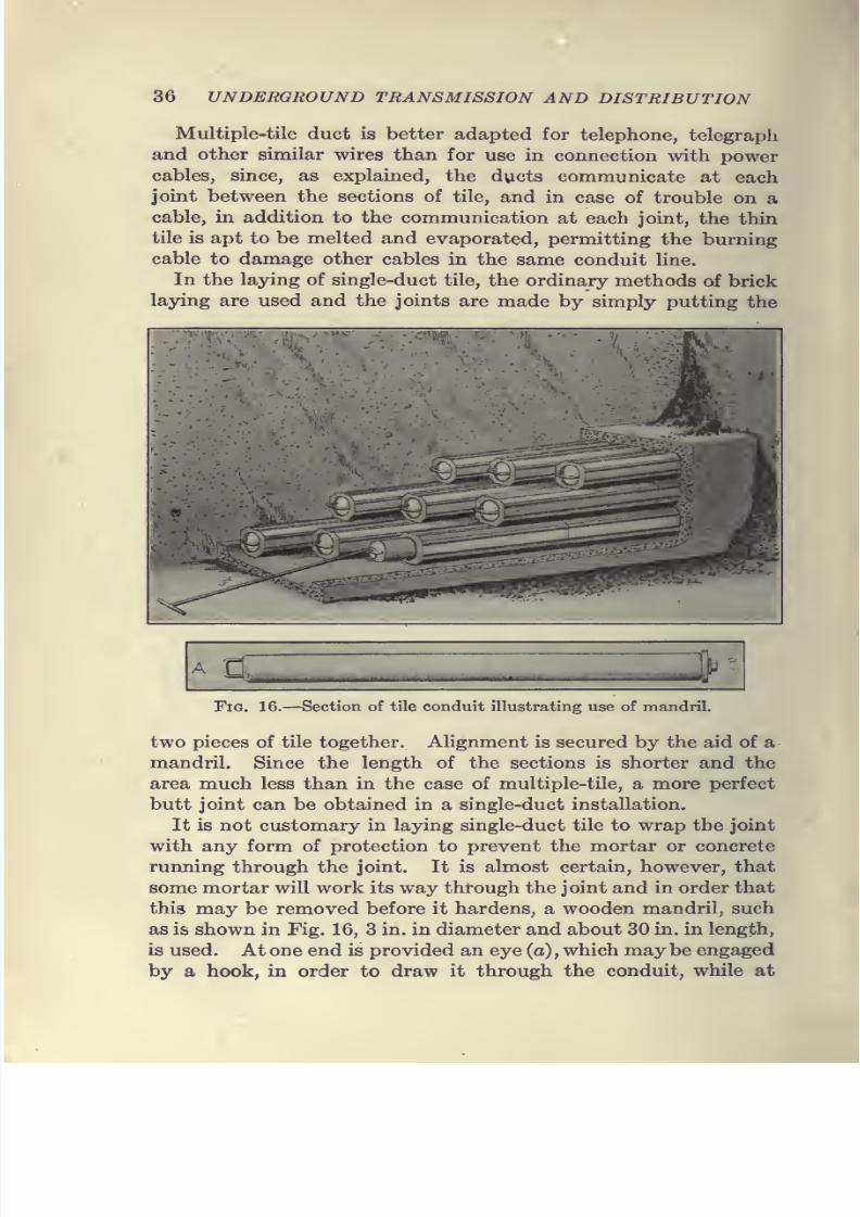
In the laying of single-duct tile, the ordinary methods of brick
laying are used and the joints are made by simply putting the
mm§
Fig. 16.—Section of tile conduit illustrating use of mandril.
two pieces of tile together. Alignment is secured by the aid of a
mandril. Since the length of the sections is shorter and the
area much less than in the case of multiple-tile, a more perfect
butt joint can be obtained in a single-duct installation.
It is not customary in laying single-duct tile to wrap the joint
with any form of protection to prevent the mortar or concreterunning through the joint. It is almost certain, however, that
some mortar will work its way through the joint and in order that
this may be removed before it hardens, a wooden mandril, such
as is shown in Fig. 16, 3 in. in diameter and about 30 in. in length,
is used. At one end is provided an eye (a), which may be engaged
by a hook, in order to draw it through the conduit, while at
7/28/2019 Underground Trans 00 Me Yeu of t
http://slidepdf.com/reader/full/underground-trans-00-me-yeu-of-t 49/327
7/28/2019 Underground Trans 00 Me Yeu of t
http://slidepdf.com/reader/full/underground-trans-00-me-yeu-of-t 50/327

7/28/2019 Underground Trans 00 Me Yeu of t
http://slidepdf.com/reader/full/underground-trans-00-me-yeu-of-t 51/327
7/28/2019 Underground Trans 00 Me Yeu of t
http://slidepdf.com/reader/full/underground-trans-00-me-yeu-of-t 52/327
40 UNDERGROUND TRANSMISSION AND DISTRIBUTION
the joints may be removed before it has a chance to harden.
Where it is necessary to cut pieces of the tile for fitting lengths
together, the tile is notched all around at the desired point bymeans of a hammer and cold chisel. It should break off at the
mark after continued chipping, though it frequently happens that
the cracks run off in some other direction. It is, preferable,
therefore, to have fitter lengths, furnished by the manufacturer.
Stone Duct.—Stone duct has been used quite extensively in the
City of Chicago. It is made of a high grade of limestone and
Portland cement, in the proportions of 4.75 to 1.00, the materials
being thoroughly blended together with water.
Moulded-stone duct is manufactured under the Graham process
and is moulded in two half moulds or sections in especially
designed machines. This mould contains a mandrel form that is
displaced by a larger mandrel having a tapered steel point.
Both mandrels are revolved by means of individual motors and
the tables holding the moulds are moved parallel with the
mandrels. As the form is displaced by the tapered steel points,
all inequalities in filling are eliminated.This method insures a perfectly smooth inner and outer sur-
face of the pipes. After being removed from the conduit
machines, the ducts are allowed to stay in the lower half of
the mould for 48 hr. to take their initial set. They are then
placed in racks and sprinkled continuously for about 6 weeks to
insure their perfect curing, after which they are allowed to dry
for 2 weeks. They are then ready for use. The ducts are made
in 5-ft. lengths and the units are provided with metal rings.
These rings, which are used for connecting two sections together
afford a tight joint, making it impossible for any foreign material
to get into the duct. It is claimed that this type of conduit is
not injured even by the short-circuiting of heavy power cables.
In this way communication of trouble from one duct to another
is avoided.
This conduit is laid with an envelope of concrete. It forms a
monolithic mass as the envelope makes an excellent bond with
the duct. The ducts can be readily cut with an ordinary cross-
cut saw, and the weight of the duct is approximately the same
as that of tile duct. With the use of metal sleeves, unskilled
labor may be employed in its installation. Its length permits of
the same staggering as is obtained with the use of fiber conduit.
The conduit is made up in various forms and in split sections,
7/28/2019 Underground Trans 00 Me Yeu of t
http://slidepdf.com/reader/full/underground-trans-00-me-yeu-of-t 53/327
CONDUIT AND- MANHOLE CONSTRUCTION 41
thus allowing repairs to be made in ducts carrying cables. It
weighs approximately 7)^ lb. per ft., has a bore of Z}4 in., with
a wall % in. thick and approximately 4,000 ft. can be loaded for
shipment on a standard car.
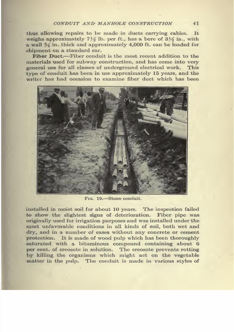
Fiber Duct.—Fiber conduit is the most recent addition to the
materials used for subway construction, and has come into very
general use for all classes of underground electrical work. This
type of conduit has been in use approximately 15 years, and the
writer has had occasion to examine fiber duct which has been
Fig. 19.—Stone conduit.
installed in moist soil for about 10 years. The inspection failed
to show the slightest signs of deterioration. Fiber pipe was
originally used for irrigation purposes and was installed under the
most unfavorable conditions in all kinds of soil, both wet and
dry, and in a number of cases without any concrete or cement
protection. It is made of wood pulp which has been thoroughly
saturated with a bituminous compound containing about 6
per cent, of creosote in solution. The creosote prevents rotting
by killing the organisms which might act on the vegetable
matter in the pulp. The conduit is made in various styles of
7/28/2019 Underground Trans 00 Me Yeu of t
http://slidepdf.com/reader/full/underground-trans-00-me-yeu-of-t 54/327
42 UNDERGROUND TRANSMISSION AND DISTRIBUTION
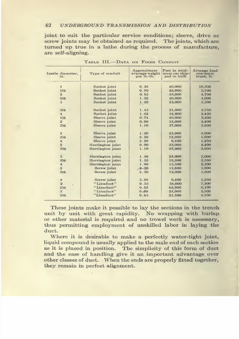
joint to suit the particular service conditions; sleeve, drive or
screw joints may be obtained as required. The joints, which are
turned up true in a lathe during the process of manufacture,
are self-aUgning.
7/28/2019 Underground Trans 00 Me Yeu of t
http://slidepdf.com/reader/full/underground-trans-00-me-yeu-of-t 55/327
CONDUIT AND MANHOLE CONSTRUCTION 43
Tests which have been conducted on fiber, show that it will
withstand a puncture test of 32,000 volts when dry and 24,000
volts after immersion in water for about 200 hr. It is imperviousto moisture, gases, acids and other corrosive elements and as it
is a non-conductor, troubles from stray currents are negligible.
The non-abrasive feature of the conduit is very important,
as it permits of drawing cables into the ducts without injury to
the sheaths by such grinding or cutting action as often results
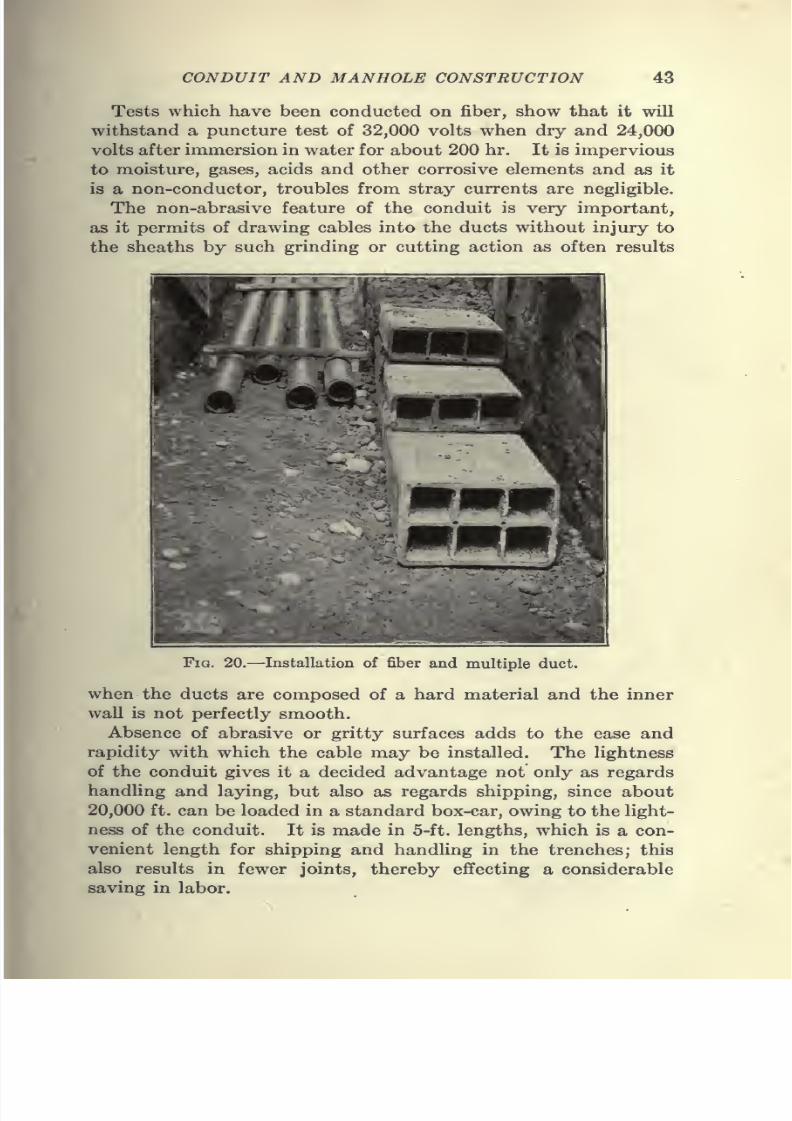
Fig. 20.—Installation of fiber and multiple duct.
when the ducts are composed of a hard material and the inner
wall is not perfectly smooth.
Absence of abrasive or gritty surfaces adds to the ease and
rapidity with which the cable may be installed. The lightness
of the conduit gives it a decided advantage not only as regards
handling and laying, but also as regards shipping, since about
20,000 ft. can be loaded in a standard box-car, owing to the light-
ness of the conduit. It is made in 5-ft. lengths, which is a con-
venient length for shipping and handling in the trenches; this
also results in fewer joints, thereby effecting a considerable
saving in labor.
7/28/2019 Underground Trans 00 Me Yeu of t
http://slidepdf.com/reader/full/underground-trans-00-me-yeu-of-t 56/327
44 UNDERGROUND TRANSMISSION AND DISTRIBUTION
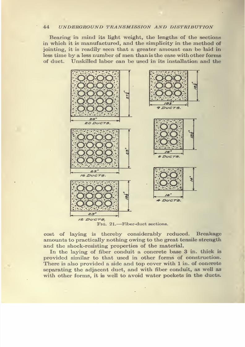
Bearing in mind its light weight, the lengths of the sections
in which it is manufactured, and the simpUcity in the method of
jointing, it is readily seen that a greater amount can be laid in
less time by a less number of men than is the case with other forms
of duct. Unskilled labor can be used in its installation and the
7/28/2019 Underground Trans 00 Me Yeu of t
http://slidepdf.com/reader/full/underground-trans-00-me-yeu-of-t 57/327
7/28/2019 Underground Trans 00 Me Yeu of t
http://slidepdf.com/reader/full/underground-trans-00-me-yeu-of-t 58/327
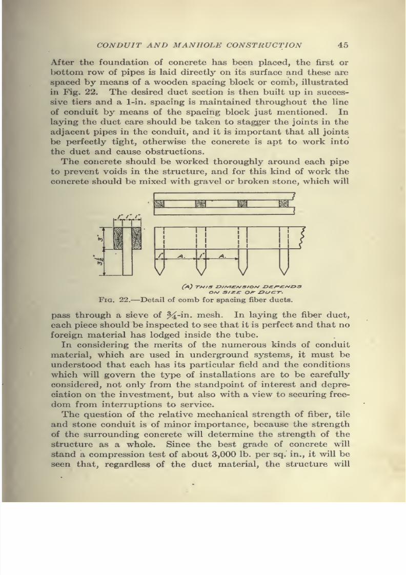
46 UNDERGROUND TRANSMISSION AND DISTRIBUTION
have sufficient strength to meet the most exacting demands of
service conditions.
Manhole Construction.—Manholes are usually built at street
intersections or turns in the conduit line, to afford a place for
jointing the cables. The distance between these manholes
depends on local conditions. It is safe to say that this limiting
distance, where large cables are to be employed, should be
500 ft.
In pulling in long runs of cable, the sheath is subjected to
severe strains which are to be limited as much as possible.
Manholes designed for high-tension cables should be spacious
and should have good drainage facilities. Their design should
be such as to avoid sharp bends between the point where the
cables enter and the position on the manhole wall where they are
to be jointed and racked. '
Ample facilities should be provided in each manhole for the
shelves or racks on which the cables are to be supported. Manycables have had to be renewed on account of insufficient manhole
room and careless racking.
It is also wise to give some attention to the location of the lower
and top ducts in the manholes to permit drawing in cables
without damaging them.
Manhole covers are preferably located at the center of the
manhole making it easy to set and rack cables and rendering it
impossible for careless workmen to ruin the cables by using them
as steps in entering and leaving manholes.
In transmission systems it is very desirable, as previously
stated, to limit the distance between manholes to less than 500
ft., as this permits of carrying in stock standard lengths of cable
which can be used in any part of the transmission line. Wher-
ever practicable manholes should be connected to sewers so
that the water will run off. A suitable trap should be employed
to prevent the sewer water from backing up and filling the man-
hole or conduit line. Where it is impossible to make the neces-
sary connection to the sewer, the following method may be used
to advantage:
When excavating for manhole work, a hole a trifle deeper
and larger than an ordinary barrel is dug and a barrel without
top or bottom placed in it; the outside of the barrel is surrounded
with a concrete covering about 3 in. thick and the barrel filled
with gravel or small stones. The concrete foundation of the
7/28/2019 Underground Trans 00 Me Yeu of t
http://slidepdf.com/reader/full/underground-trans-00-me-yeu-of-t 59/327
CONDUIT AND MANHOLE CONSTRUCTION 47
manhole should then be laid and the top of the barrel set flush
with the floor.
The tendency in the past has been to give too little attention
to the matter of future requirements and this has resulted in
the very congested condition of cables and equipment now found
in the manholes of many of our large cities. The importance of
providing adequate facilities will be appreciated when it is con-
sidered that the efficiency of men, when working under cramped
conditions, is seriously impaired.
Sewer and Illuminating Gas.—In the construction of manholes,
provisions should be made for sufficient ventilation to carry off
any gases which may accumulate.
The gases most commonly found in manholes are sewer gas
and illuminating gas, and now, with the extensive use of automo-
biles, we may find gasolene vapors mixed with the sewer gas.
Sewer gas consists of approximately 90 parts of nitrogen,
2 to 4 parts of oxygen, 1 to 3 parts of carbon dioxide, 3 to 5
parts of carbon monoxide, methane and other gases. It has an
odor due to the organic decomposition constantly going on in thesewers. It is not poisonous in the true sense of the word, but,
due to its high percentage of nitrogen and its low percentage of
oxygen, there is not a sufficient amount of oxygen to support
respiration, and hence a person is slowly smothered in an
atmosphere of this gas. It is non-explosive in itself, and, due to
its high nitrogen and low oxygen content, would, undoubtedly,
prevent the explosion of otherwise explosive gas when mixed with
it. This gas easily finds itsway into the conduit lines through theentrapped connections which the manholes have with the sewers.
Illuminating gas, or city gas, as generally distributed, may be
coal gas, water gas, Solvay gas, or a mixture of any two or all of
these gases. It is colorless, but usually has a strong penetrating
odor, so that a small percentage may readily be detected by the
sense of smell. It is very poisonous in itself and with air forms
a highly explosive mixture. Gas mains and distribution lines are
closelyinterwoven
with the conduit lines and breaks or leaks in
the gas system lead to the escape of the gas into the conduits and
manholes.
Sealing of Ducts in Manholes.—When troubles occur in which
there is an arc in series with considerable resistance, the lack of
sufficient oxygen for the combustion of the gases, which are gener-
ated, will cause these gases to flow through the conduits and burn
7/28/2019 Underground Trans 00 Me Yeu of t
http://slidepdf.com/reader/full/underground-trans-00-me-yeu-of-t 60/327
48 UNDERGROUND TRANSMISSION AND DISTRIBUTION
in adjacent manholes, unless there is some positive barrier to
prevent the gas flowing between manholes. It is, therefore,
considered advisable to cement the ducts in each manhole along
the heavier runs of cable where the spreading gas could cause
the greatest damage. Some companies using concentric cables,
subject to creeping on accoimt of expansion and contraction
at periods of heavy and light loads, do not consider it advisable
to cement the ducts. They also consider the omission of the
sealing of the ducts an advantage from the standpoint of provid-
ing more ventilation to the manholes and, therefore, less chance
of accumulation of gases, and perhaps increased heat radiation
in the ducts. All ducts or pipes leading from manholes to the
premises of customers should be cemented in the subway and
at the entrance into the customer's buildings to prevent obnoxious
gases entering the premises. Several devices are on the market
which have been designed to be placed in the duct before apply-
ing a mortar to aid in removing the latter. A weak cement
mortar is sufficient for this purpose.
Types of Manhole Construction.—Manhole construction maybe classified under three headings
(a) Brick construction.
(&) Monolithic concrete construction.
(c) Concrete block construction.
The design of each of these three types of construction may be
divided into two classes: namely, design to properly facilitate
the training of cables for transmission purposes; and design to
provide for the training of cables for distribution purposes, in-
cluding the installation of transformers, boxes, and other sub-
surface equipment.
MonoHthic concrete seems to be advocated for manhole con-
struction, particularly where a number of manholes of the same
size are to be built, and where local conditions and the space
available in the street will permit the use of a standard form.
One of the advantages of the use of monolithic concrete for man-
hole construction is the fact that common labor may be employed
for mixing and placing the concrete, whereas, with brick construc-
tion, the service of experienced masons is necessary. Brick
construction seems to be very desirable in congested sections
where the use of either a wooden or metal form for concrete work
would be almost prohibitive on account of the high cost of special
forms to meet the local conditions.
7/28/2019 Underground Trans 00 Me Yeu of t
http://slidepdf.com/reader/full/underground-trans-00-me-yeu-of-t 61/327
CONDUIT AND MANHOLE CONSTRUCTION 49
One of the disadvantages in the use of concrete manholes lies
in the fact that the soil in many locations is sandy clay, which
will not stand unless properly supported by bracing. The result
of this soil condition is that in the locations where the absence
of other constructions permits the use of concrete manholes, the
soil requires an outer as well as an inner form. In such cases the
resulting cost is higher than for brick manholes. The presence
of water in some localities at a depth of 3 or 4 ft. makes it neces-
sary to build brick manholes. In such locations, a manhole of
brick can be built by driving sheet piling and using a sufficient
number of pumps to remove the water from the hole. The brick-work is started directly upon the sand and the manhole is filled
up with sand as the work progresses. This prevents the water
which seeps into the hole washing out the mortar of the
brickwork.
Building Manholes in. Quicksand.—It is frequently necessary
to build manholes in a sandy soil when the permanent water level
is only 2 or 3 ft. below the surface, and in such cases manholes
have been successfullybuilt
byusing
a modified form of open-caisson construction. The excavation to the quicksand is made
in the ordinary manner. Then a wooden framework is built,
having the same horizontal section as the manhole wall. This
framework is built up of 2-in. planks to a total thickness of 6 in,,
the corners being well fastened to eliminate diagonal bracing and
leave the center of the framework free for the excavation. The
framework is then placed in a level position on the quicksand and
the manhole is built of brick to the required height, the walls
being well plastered on the outside.
After setting for 3 or 4 days, the excavation of the manhole
proceeds. By digging along the walls inside of the manhole and
under the wooden framework, the manhole will usually settle
to the required depth. During the excavation only sufficient
water should be removed to allow the men to work to advantage,
as otherwise the sand becomes quite hard. The settlement, if
slow, can be accelerated by placing bags of sand or other weights
on top of the manhole walls. Ordinarily the excavation and
settlement of the manholes to the required depth will not require
more than 8 or 10 hr. unless obstructions are encountered. After
the manhole has reached the proper depth, the settlement is
stopped by backfilling the excavation and tamping around the
outside of the manhole wall.
4
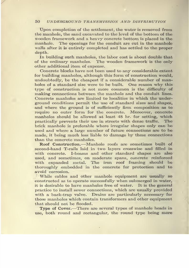
7/28/2019 Underground Trans 00 Me Yeu of t
http://slidepdf.com/reader/full/underground-trans-00-me-yeu-of-t 62/327
50 UNDERGROUND TRANSMISSION AND DISTRIBUTION
Upon completion of the settlement, the water is removed from
the manhole, the sand excavated to the level of the bottom of the
wooden framework and a heavy concrete bottom is placed in the
manhole. The openings for the conduit are cut in the manhole
walls after it is entirely completed and has settled to the proper
depth.
In building such manholes, the labor cost is about double that
of the ordinary manholes. The wooden framework is the only
other additional item of expense.
Concrete blocks have not been used to any considerable extent
for building manholes, although this form of construction would,
undoubtedly, be the cheapest if a considerable number of man-
holes of a standard size were to be built. One reason why this
type of construction is not more common is the difficulty of
making connections between the manhole and the conduit lines.
Concrete manholes are limited to localities in which the under-
ground conditions permit the use of standard sizes and shapes,
and where the ground is of sufficiently firm composition as to
require no outer form for the concrete. Moreover, concrete
manholes should be allowed at least 48 hr. for setting, which
practically prevents their use in streets with dense traffic. The
brick manhole is preferable where irregular shapes only can be
used and where a large number of future connections are to be
made, it being much less liable to damage by these connections
than the concrete manholes.
Roof Construction.—Manhole roofs are sometimes built of
second-hand T-rails laid in two layers crosswise and filled in
with concrete. I-beams and other standard shapes are also
used, and sometimes, on moderate spans, concrete reinforced
with expanded metal. The iron roof framing should be
thoroughly embedded in the concrete for protection and to
avoid corrosion.
While cables and other manhole equipment are usually so
constructed as to operate successfully when submerged in water,
it is
desirable to have manholes free of water. Itis
the generalpractice to install sewer connections, which are usually provided
with a back-trap valve. Drains are particularly necessary for
those manholes which contain transformers and other equipment
that should not be flooded.
T3rpe of Cover.—There are several types of manhole heads in
use, both round and rectangular, the round type being more
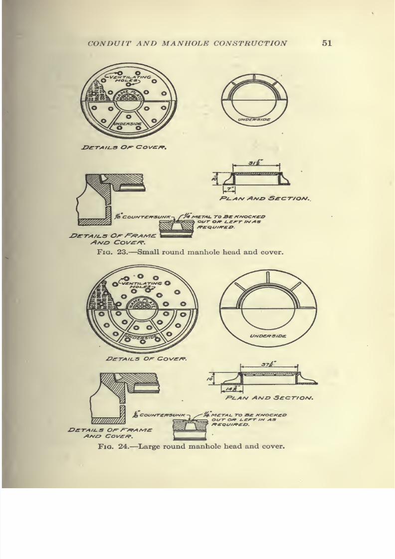
7/28/2019 Underground Trans 00 Me Yeu of t
http://slidepdf.com/reader/full/underground-trans-00-me-yeu-of-t 63/327

7/28/2019 Underground Trans 00 Me Yeu of t
http://slidepdf.com/reader/full/underground-trans-00-me-yeu-of-t 64/327
52 UNDERGROUND TRANSMISSION AND DISTRIBUTION
generally used. The use of rectangular covers should be avoided
as far as possible, as in the hands of careless workmen the cover
may be dropped into the manhole causing damage to cables and
equipment. Some companies use an inner cover, which is
fastened tightly to the outer frame by means of a lock bar and nut
and made waterproof by a rubber gasket. In some installations
this inner cover is intended only for a pan to catch the dirt which
To^ANn UnP£/^S/D£: 0/=" CO \/^f?.
S£CT/oN Of- F'^AMe: /Ia/z? Cov£f?.
Fig. 25.—Square manhole frame and cover.
falls through the ventilated outer cover. Such pans, however,
are not in general use. Ventilated covers are quite necessary in
streets where conduits and gas mains parallel each other in close
proximity, as without ventilation there is always danger of gas
explosions and fires in the manholes.
When manholes are constructed in unimproved streets, it is
well to allow for any uncertainty regarding the exact grade of the
finished paving. If, therefore, the roof is built about 4 in. low
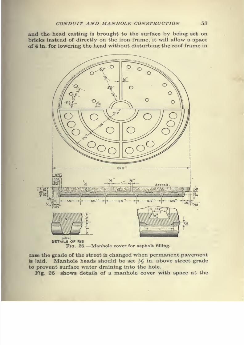
7/28/2019 Underground Trans 00 Me Yeu of t
http://slidepdf.com/reader/full/underground-trans-00-me-yeu-of-t 65/327
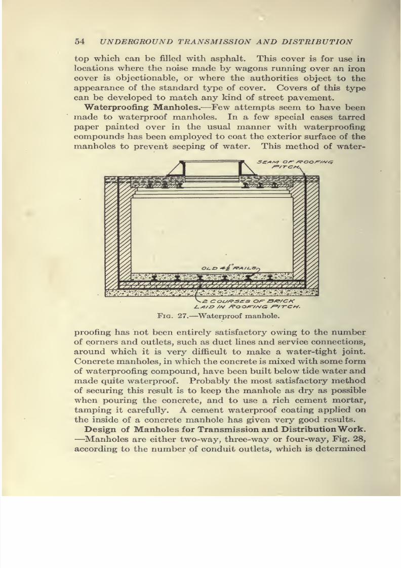
7/28/2019 Underground Trans 00 Me Yeu of t
http://slidepdf.com/reader/full/underground-trans-00-me-yeu-of-t 66/327
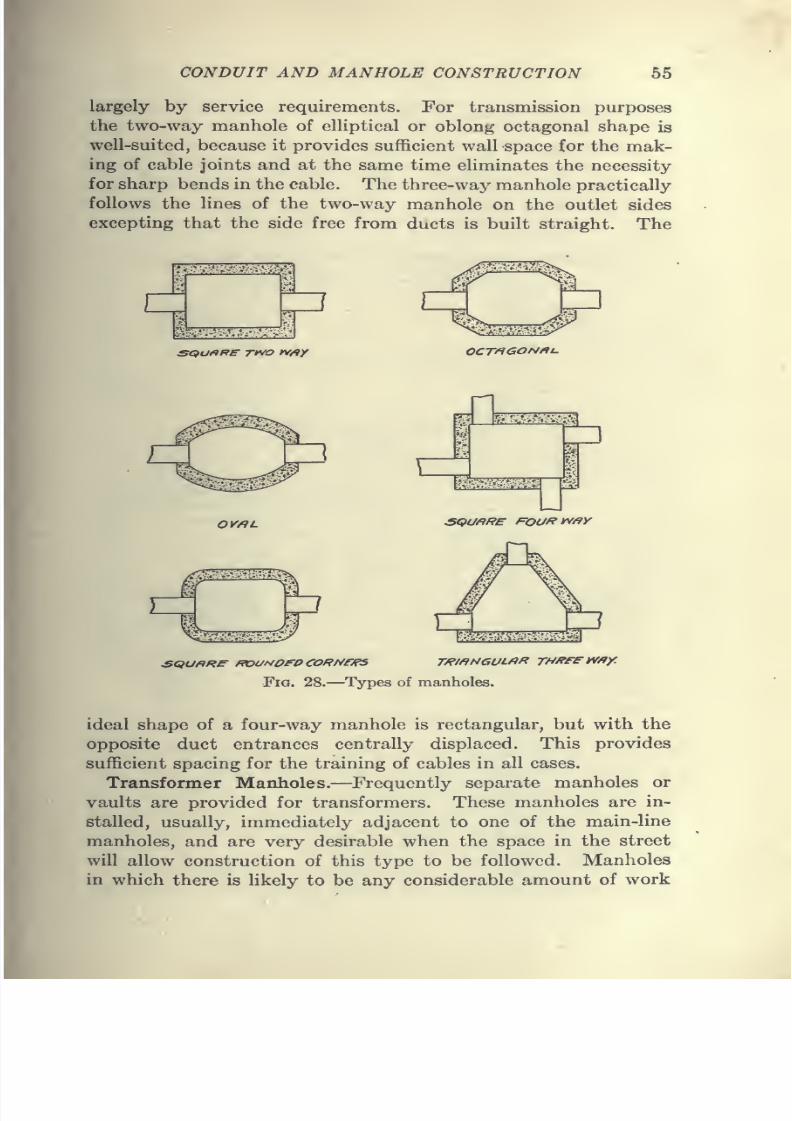
7/28/2019 Underground Trans 00 Me Yeu of t
http://slidepdf.com/reader/full/underground-trans-00-me-yeu-of-t 67/327
CONDUIT AND MANHOLE CONSTRUCTION 55
largely by service requirements. For transmission purposes
the two-way manhole of elliptical or oblong octagonal shape is
well-suited, because it provides sufficient wall space for the mak-
ing of cable joints and at the same time eliminates the necessity
for sharp bends in the cable. The three-way manhole practically
follows the lines of the two-way manhole on the outlet sides
excepting that the side free from ducts is built straight. The
se)u»Re Tivo IV/9Y
1
0CT^6ON»u
\inM^iit:^
;p
OV/RL ^^uftRE Fouf^y^'^y
Fig. 28.—Types of manholes.
ideal shape of a four-way manhole is rectangular, but with the
opposite duct entrances centrally displaced. This provides
sufficient spacing for the training of cables in all cases.
Transformer Manholes.—Frequently separate manholes or
vaults are provided for transformers. These manholes are in-
stalled, usually, immediately adjacent to one of the main-line
manholes, and are very desirable when the space in the street
will allow construction of this type to be followed. Manholes
in which there is likely to be any considerable amount of work
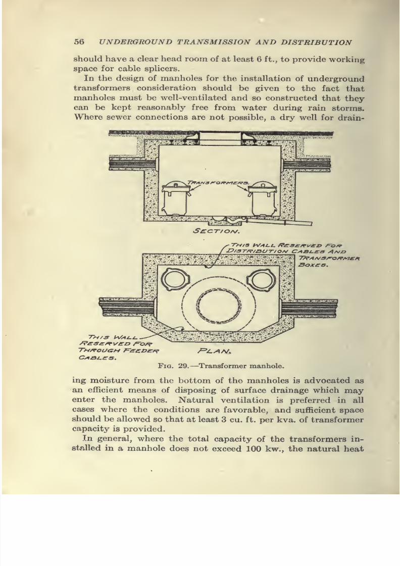
7/28/2019 Underground Trans 00 Me Yeu of t
http://slidepdf.com/reader/full/underground-trans-00-me-yeu-of-t 68/327
56 UNDERGROUND TRANSMISSION AND DISTRIBUTION
should have a clear head room of at least 6 ft., to provide working
space for cable splicers.
In the design of manholes for the installation of undergroundtransformers consideration should be given to the fact that
manholes must be well-ventilated and so constructed that they
can be kept reasonably free from water during rain storms.
Where sewer connections are not possible, a dry well for drain-
pampa
'^
tiils^
S£c-r/OA/.
This h/^t,i, Rcas/rveb f=off
Fig. 29.—Transformer manhole.
ing moisture from the bottom of the manholes is advocated as
an efficient means of disposing of surface drainage which mayenter the manholes. Natural ventilation is preferred in all
cases where the conditions are favorable, and sufficient space
should be allowed so that at least 3 cu. ft. per kva. of transformer
capacity is provided.
In general, where the total capacity of the transformers in-
stalled in a manhole does not exceed 100 kw., the natural heat
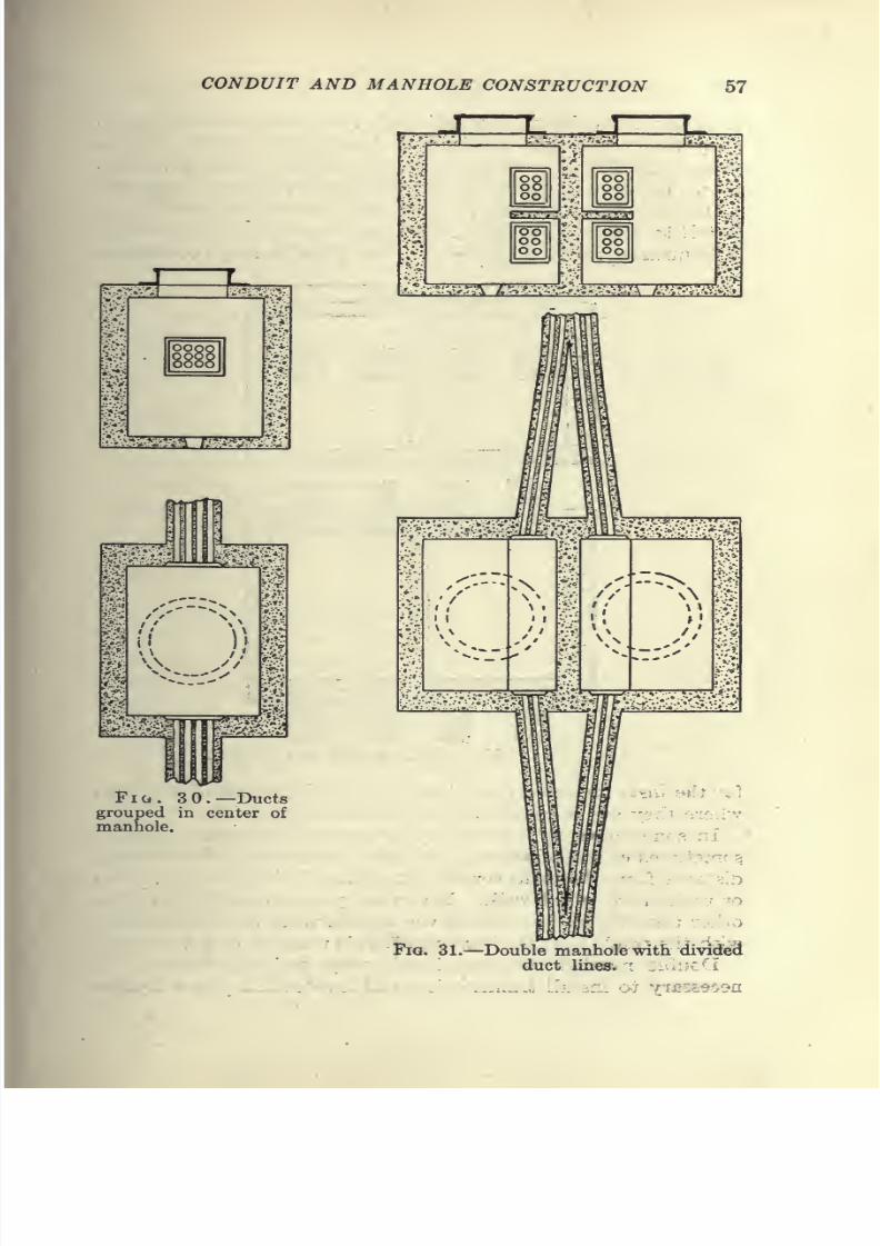
7/28/2019 Underground Trans 00 Me Yeu of t
http://slidepdf.com/reader/full/underground-trans-00-me-yeu-of-t 69/327
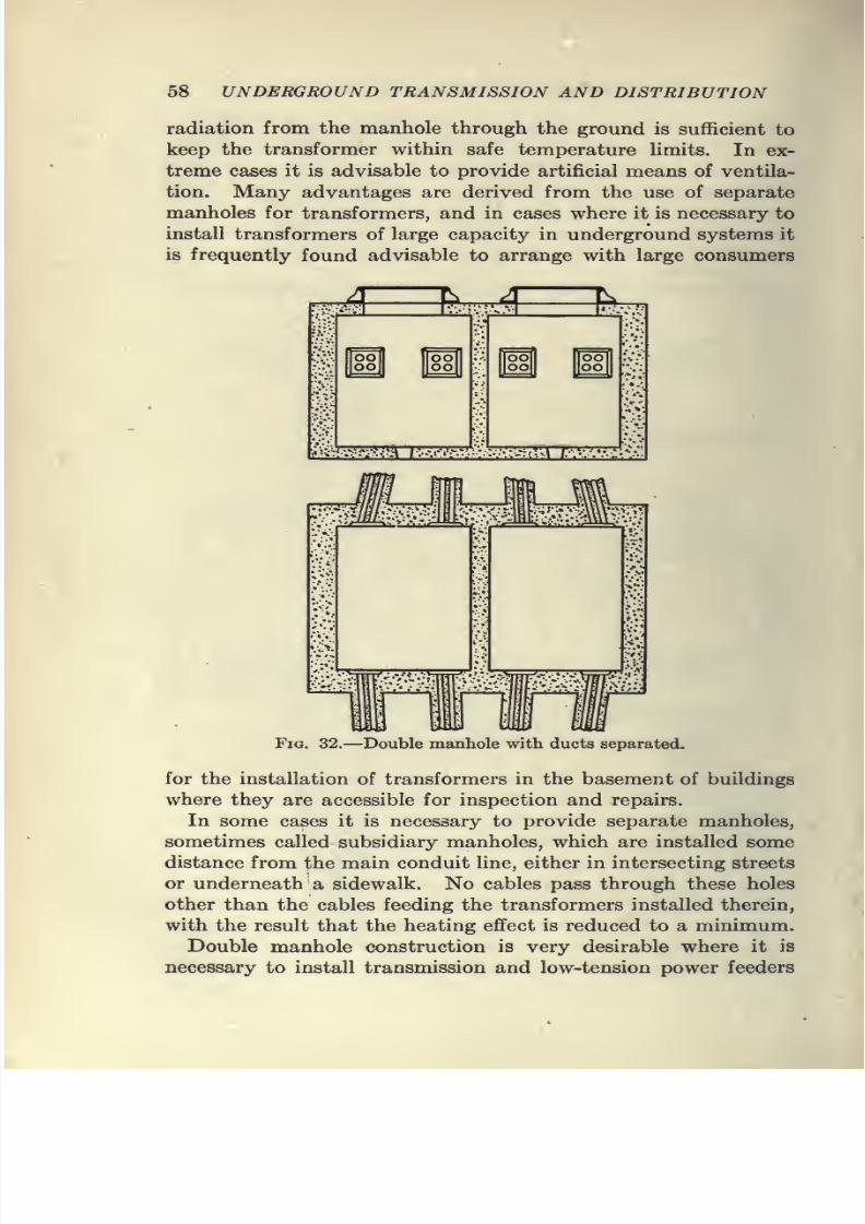
7/28/2019 Underground Trans 00 Me Yeu of t
http://slidepdf.com/reader/full/underground-trans-00-me-yeu-of-t 70/327
58 UNDERGROUND TRANSMISSION AND DISTRIBUTION
radiation from the manhole through the ground is sufficient to
keep the transformer within safe temperature limits. In ex-
treme cases it is advisable to provide artificial means of ventila-
tion. Many advantages are derived from the use of separate
manholes for transformers, and in cases where it is necessary to
install transformers of large capacity in underground systems it
is frequently found advisable to arrange with large consumers
Fig. 32.—Double manhole with ducts separated.
for the installation of transformers in the basement of buildings
where they are accessible for inspection and repairs.
In some cases it is necessary to provide separate manholes,
sometimes called subsidiary manholes, which are installed some
distance from the main conduit line, either in intersecting streets
or underneath a sidewalk. No cables pass through these holes
other than the cables feeding the transformers installed therein,
with the result that the heating effect is reduced to a minimum.
Double manhole construction is very desirable where it is
necessary to install transmission and low-tension power feeders
7/28/2019 Underground Trans 00 Me Yeu of t
http://slidepdf.com/reader/full/underground-trans-00-me-yeu-of-t 71/327
CONDUIT AND MANHOLE CONSTRUCTION 59
in the same conduit line. In such installations a dividing wall
in the manhole permits the complete separation of high-tension
and low-tension cables.
The ducts in some cases run straight through the manhole
wall, Fig. 30, to the center of the manhole, where the cables divide,
half going to one side and half to the other, the cables being
racked on the manhole wall. Grouping of ducts in this manner
is very objectionable on account of the sharp bends in the cable,
which may crack the insulation and cause breakdowns. Rise
in temperature in one cable is readily communicated to another
when the ducts are grouped in this manner.
The form of construction adopted by the Niagara Falls Power
Co. for one of their recent installations is shown in Fig. 31.
Where the space in the street will permit of this design, very
satisfactory results may be obtained:
In places where rock is near the surface necessitating shallow
excavation and affording excellent conditions for the radiation
of heat, the type of construction illustrated in Fig. 32 will give
good service.
All of these special methods depend upon local conditions in
the streets and can be used only where foreign structures do not
interfere.
In Fig. 33 is illustrated a typical design of a two-way manhole,
as recommended by the Committee on Power Distribution of the
Railway Engineering Association. This type of hole is well-
adapted to railway service, as it permits the installation of heavy
power cables in almost a straight Une, very Uttle bending of the
cable being required, and the slack in the manhole being reduced
to a minimum. It will be noted that every third layer of bricks
is projected to act as a shelf :^or the cables, and while this may be
good construction for railway feeders which as a rule run straight
through the manhole, for electric light and power cables, the
installation of shelves of this type is not so desirable. Manholes
for electric light and power cables frequently contain junction
boxes and other equipment, and to facilitate their installation,
smooth walls are desirable, the cables being racked on the wall
by means of portable hangers conveniently arranged. The
installation of eye-bolts, as shown in the sketch, is a very good
feature, as by their use the drawing in of cables is much simpli-
fied. Bolts of this type should be installed in all manholes, as it
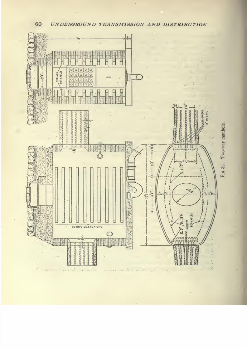
7/28/2019 Underground Trans 00 Me Yeu of t
http://slidepdf.com/reader/full/underground-trans-00-me-yeu-of-t 72/327
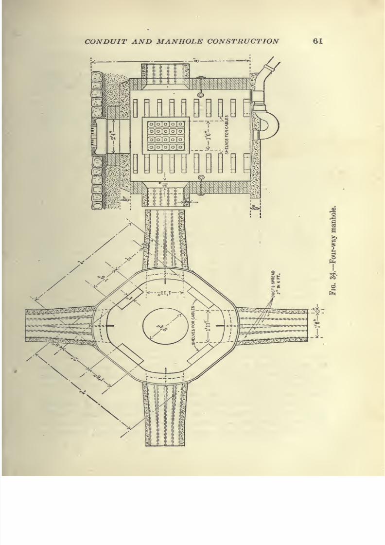
7/28/2019 Underground Trans 00 Me Yeu of t
http://slidepdf.com/reader/full/underground-trans-00-me-yeu-of-t 73/327
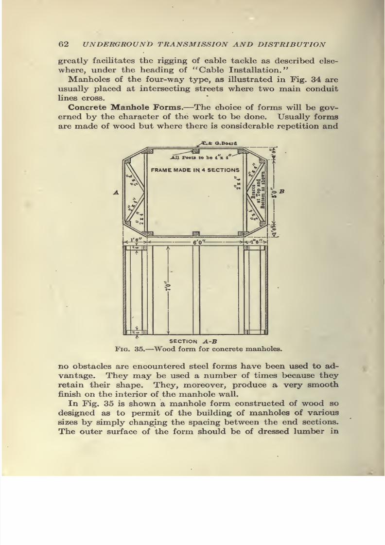
7/28/2019 Underground Trans 00 Me Yeu of t
http://slidepdf.com/reader/full/underground-trans-00-me-yeu-of-t 74/327
62 UNDERGROUND TRANSMISSION AND DISTRIBUTION
greatly facilitates the rigging of cable tackle as described else-
where, under the heading of "Cable Installation."
Manholes of the four-way type, as illustrated in Fig. 34 are
usually placed at intersecting streets where two main conduit
lines cross.
Concrete Manhole Forms.—The choice of forms will be gov-
erned by the character of the work to be done. Usually forms
are made of wood but where there is considerable repetition and
^/^^ Q.l
*k^:"6''»
SECTION A-B
Fia. 35.—Wood form for concrete manholes.
no obstacles are encountered steel forms have been used to ad-
vantage. They may be used a number of times because they
retain their shape. They, moreover, produce a very smooth
finish on the interior of the manhole wall.
In Fig. 35 is shown a manhole form constructed of wood so
designed as to permit of the building of manholes of various
sizes by simply changing the spacing between the end sections.
The outer surface of the form should be of dressed lumber in
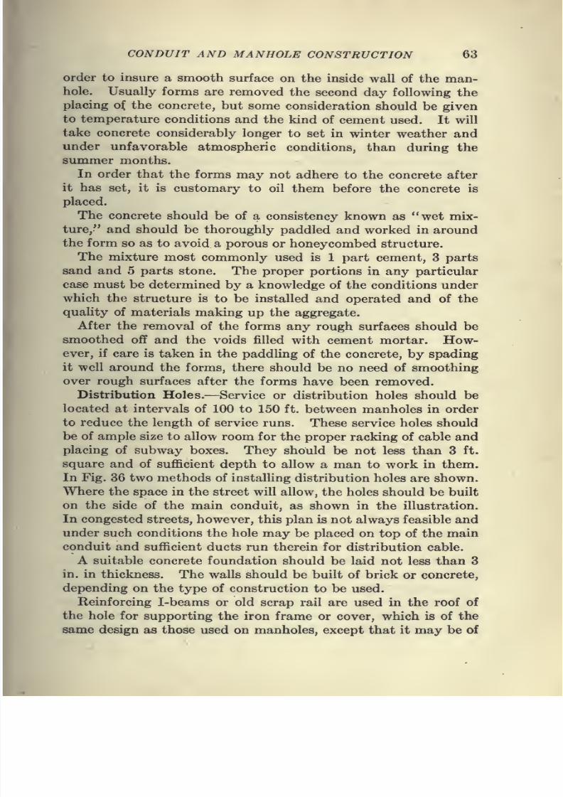
7/28/2019 Underground Trans 00 Me Yeu of t
http://slidepdf.com/reader/full/underground-trans-00-me-yeu-of-t 75/327
CONDUIT AND MANHOLE CONSTRUCTION 63
order to insure a smooth surface on the inside wall of the man-
hole. Usually forms are removed the second day following the
placingof
the concrete,but some consideration should be given
to temperature conditions and the kind of cement used. It will
take concrete considerably longer to set in winter weather and
under unfavorable atmospheric conditions, than during the
summer months.
In order that the forms may not adhere to the concrete after
it has set, it is customary to oil them before the concrete is
placed.
The concrete should be of a consistency known as "wet mix-
ture," and should be thoroughly paddled and worked in around
the form so as to avoid a porous or honeycombed structure.
The mixture most commonly used is 1 part cement, 3 parts
sand and 5 parts stone. The proper portions in any particular
case must be determined by a knowledge of the conditions under
which the structure is to be installed and operated and of the
quality of materials making up the aggregate.
After the removal of the forms any rough surfaces should be
smoothed off and the voids filled with cement mortar. How-
ever, if care is taken in the paddling of the concrete, by spading
it well around the forms, there should be no need of smoothing
over rough surfaces after the forms have been removed.
Distribution Holes.—Service or distribution holes should be
located at intervals of 100 to 150 ft. between manholes in order
to reduce the length of service runs. These service holes should
be of ample size to allow room for the proper racking of cable and
placing of subway boxes. They should be not less than 3 ft.
square and of sufficient depth to allow a man to work in them.
In Fig. 36 two methods of installing distribution holes are shown.
Where the space in the street will allow, the holes should be built
on the side of the main conduit, as shown in the illustration.
In congested streets, however, this plan is not always feasible and
under such conditions the hole may be placed on top of the main
conduit and sufficient ducts run therein for distribution cable.
A suitable concrete foundation should be laid not less than 3
in. in thickness. The walls should be built of brick or concrete,
depending on the type of construction to be used.
Reinforcing I-beams or old scrap rail are used in the roof of
the hole for supporting the iron frame or cover, which is of the
same design as those used on manholes, except that it may be of
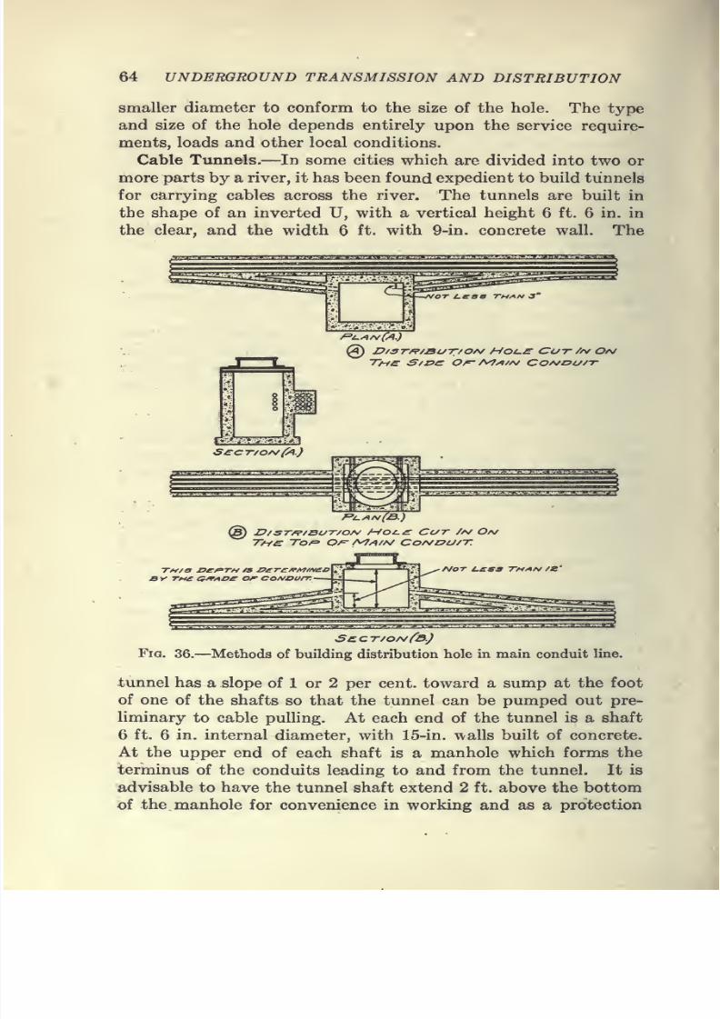
7/28/2019 Underground Trans 00 Me Yeu of t
http://slidepdf.com/reader/full/underground-trans-00-me-yeu-of-t 76/327
64 UNDERGROUND TRANSMISSION AND DISTRIBUTION
smaller diameter to conform to the size of the hole. The type
and size of the hole depends entirely upon the service require-
ments, loads and other local conditions.
Cable Tunnels.—In some cities which are divided into two or
more parts by a river, it has been found expedient to build tunnels
for carrying cables across the river. The tunnels are built in
the shape of an inverted U, with a vertical height 6 ft. 6 in. in
the clear, and the width 6 ft. with 9-in. concrete wall. The
@ D/ST/p/BuT/ o/^ Hoi.£ Cot- //v Ov
rS"?^-./!
S£C7~/OA/{^.)
@ D/STf^/BUT/0/\/ MOi.£ CC/T /A/ O/V
jy tmc a^/toe or coa/ou/t.-
• /\/OT I.CS3 THAf^ /Z
Scct/onCb.)
Fig. 36.—Methods of building distribution hole in main conduit line.
tunnel has a slope of 1 or 2 per cent, toward a sump at the foot
of one of the shafts so that the tunnel can be pumped out pre-
liminary to cable pulling. At each end of the tunnel is a shaft
6 ft. 6 in. internal diameter, with 15-in. walls built of concrete.
At the upper end of each shaft is a manhole which forms the
terminus of the conduits leading to and from the tunnel. It is
advisable to have the tunnel shaft extend 2 ft. above the bottom
of the manhole for convenience in working and as a protection

7/28/2019 Underground Trans 00 Me Yeu of t
http://slidepdf.com/reader/full/underground-trans-00-me-yeu-of-t 77/327

7/28/2019 Underground Trans 00 Me Yeu of t
http://slidepdf.com/reader/full/underground-trans-00-me-yeu-of-t 78/327
7/28/2019 Underground Trans 00 Me Yeu of t
http://slidepdf.com/reader/full/underground-trans-00-me-yeu-of-t 79/327
7/28/2019 Underground Trans 00 Me Yeu of t
http://slidepdf.com/reader/full/underground-trans-00-me-yeu-of-t 80/327
7/28/2019 Underground Trans 00 Me Yeu of t
http://slidepdf.com/reader/full/underground-trans-00-me-yeu-of-t 81/327
7/28/2019 Underground Trans 00 Me Yeu of t
http://slidepdf.com/reader/full/underground-trans-00-me-yeu-of-t 82/327
70 UNDERGROUND TRANSMISSION AND DISTRIBUTION
15. The engineer may require the discharge from the work of any incom-
petent or unfaithful employees who may neglect to execute the work in
accordance with the specifications and the direction of the engineer, and thecontractor shall not again employ such person on any part of the work with-
out the consent of the engineer.
16. The handling of materials and all work relating thereto must be done
in compliance with the regulation established by the city authorities of the
city of The contractor shall immediately remove all
surplus material as fast as the work is finished and dispose of same at his
own cost.
17. The contractor shall furnish all necessary watchmen, place sufficient
and proper guards for the prevention of accident, and shall put up and
keep at night suitable and sufficient danger lights and barricades as required
by the ordinance of said city, and shall indemnify and save harmless the
company, its officers, agents and servants against and from all damages,
cost and expense, which they may suffer, or to which they may be put by
reason of injuries to person or property of another, resulting from negligence
or carelessness or accident on the part of said contractor.
18. The contractor must furnish all necessary guard rails, staging or
bridging that may be necessary to cover over the trenches so as to not ob-
struct public travel at crossings.
19. If, in the excavation of trenches a water main or pipe service, a line
of gas pipe, or any private or public underground service of any character
is encountered, all necessary protection from injury thereof must be provided
by the contractor, and if necessary to make any changes thereto same must
be done entirely by the contractor and to the approval of the owners; pay-
ment for same should be agreed upon in writing.
20. The contractor must assume all responsibility for damage of any kind
caused by his employees to any sewer, gas pipe, conduit or other underground
system and must make such damage good at his own cost and expense. The
repairs must be satisfactory to the owners.
21. The contractor will assume, and shall be held liable for,
any damageto property, or any accident to men or material, connected with the work
described in these specifications which may occur prior to the final comple-
tion of the work and its acceptance.
22. The contractor shall pay, discharge and satisfy all claims for material
furnished and labor done in carrying out this contract and shall fully protect
the company and from all such claims or liens on account
thereof and the bond to be given by the contractor shall comply with this
clause.
23. The contractor is to furnish such a force of men and teams, and such
labor-saving devices, such as concrete mixers, rock drills, tools, machinery,and so forth, as in the judgment of the engineer is necessary to prosecute
the work with satisfactory speed.
24. If the contractor does not prosecute said work as rapidly as in the
opinion of the engineer he should, the contractor shall employ and put
to work so many additional men, teams and labor-saving devices as the
engineer may require, and if the contractor fails to do so, the company may
7/28/2019 Underground Trans 00 Me Yeu of t
http://slidepdf.com/reader/full/underground-trans-00-me-yeu-of-t 83/327
7/28/2019 Underground Trans 00 Me Yeu of t
http://slidepdf.com/reader/full/underground-trans-00-me-yeu-of-t 84/327
7/28/2019 Underground Trans 00 Me Yeu of t
http://slidepdf.com/reader/full/underground-trans-00-me-yeu-of-t 85/327
CONDUIT AND MANHOLE CONSTRUCTION 73
placed on the sides and top. If the space between sides of conduits and sides
of trench is too great to be entirely filled with concrete, and boards are used,
these must be left in place or else withdrawn so as not to disturb concrete
or earth filling and in a manner acceptable to the engineer. All concrete
to be made of one (1) part cement, two (2) parts clean sharp
sand, and five (5) parts of screened gravel. Cement and sand to be first
thoroughly mixed dry, then a sufficient quantity of water added to form a
soft mortar; the gravel to be afterward added and thoroughly iriixed. The
concrete when placed in trench to be tamped till water flushes to the sur-
face. The placement of concrete to be so conducted as not to disturb the
conduits while mortar is setting.
38. Service laterals shall be installed by the contractor at the places
designated by the engineer and run into the basement or cellar. Theselaterals will be run with single conduit and under same specifications as the
other conduit work.
Plugs
39. Wherever and whenever work is suspended, the open end of all ducts
must be plugged with hard-wood plugs conforming accurately to the shape
of the duct, and at the larger end at least one-quarter (34) of an inch greater
in dimension than the duct.
Blasting
40. Where blasting is required, moderate charges of explosive must be
used, and the blast covered with heavy logs and chains, or other measures
taken to protect life and property. Excavation of ledge, rock or such boul-
ders as may contain ten (10) cubic feet or more will be subject to extra pay-
ments at rates hereinafter named.
RODDING
41. Upon completion of the entire work and before acceptance by the
company, the contractor will be required to pass through each duct, from
manhole to manhole, an iron or iron-shod mandrel conforming in shape
to that of the duct, and of not more than one-quarter (34) inch smaller di-
mension. Any obstruction to the free passage of the mandrel through the
ducts must be removed by the contractor at his own expense.
EXTBAS
42. No claim for extra payment is to be made except for extra work
done in obedience to written orders from the engineer approved by thecompany.
Manholes
43. Manholes and service boxes will be as shown on accompanying plans,
unless otherwise directed by the inspecting engineer. They are to be con-
structed of the best cement. Concrete mixed over one (1)
hour, or that has commenced to set, shall not be retempered or used. All
7/28/2019 Underground Trans 00 Me Yeu of t
http://slidepdf.com/reader/full/underground-trans-00-me-yeu-of-t 86/327
74 UNDERGROUND TRANSMISSION AND DISTRIBUTION
manholes shall be drained by means of a round opening located in the floor
of the manholes at such points as shall be designated by the engineer, and the
form for this opening will be furnished by the company. All service holes
must have drain tubes, supplied by the company, installed in the walls of
same, at points designated by the engineer of the company.
Manhole Frames
44. Manhole and service-hole frames and covers to be as per plans.
Each manhole and service-hole frame when set shall be bedded in cement
mortar and must be set to a line not exceeding one-half (J^) inch above grade
of finished pavement, and shall not in any event be below said grade after
settlement.
Measitrement
45. The number of duct feet to be paid for under these specifications shall
be according to the actual measurements of the finished work from face to
face of manhole walls. The manhole and service manholes will be paid
for at so much per manhole complete. Service laterals will be paid for accord-
ing to the actual measurements of the finished work from face of service
box or manhole to face of basement or cellar wall or floor line where there is
no basement or cellar. Where, owing to obstructions, manholes cannot be
built to a specified dimension, and in order to get the desired working space,
it is necessary that the manhole be constructed of a shape and size notshown on the plans; the contractor is to be paid at a unit price per cubic
yard of brick work or concrete, in the sides, top and bottom of the hole.
46. Contractor shall use every care in handling conduit, and any damage
through carelessness on his part to be replaced at his expense.
47. Any work proving defective within one (1) year after completion of
the work, if due to the use of poor material or faulty construction, or both,
shall be replaced free of charge by the contractor.
48. All walls when broken through in installing laterals as provided for
in Paragraph 38, shall be, by the contractor at his own expense, left in as good
condition as they were before such laterals were installed.
49. Test pits shall be put down at the contractor's expense wherever
thought desirable and of such size as is necessary to determine the feasible
location for the trench, manholes and service holes.
50. Particular care shall be taken not to obstruct access to fire hydrants,
manholes, catch basins and grates belonging to the city or any other cor-
poration or individual in the vicinity of the work and to arrange free passage
ways for the fire department.
51. Such ducts as may be deemed necessary for the installation of the
said conduit system across any canal or river shall be installed in proximity
to the various bridges crossing the canal or river at such points as may be
designated and approved by the company's engineer.
Bond
52. The contractor will be required to execute a bond in the sum of
with such sureties as shall be approved
by the company.
7/28/2019 Underground Trans 00 Me Yeu of t
http://slidepdf.com/reader/full/underground-trans-00-me-yeu-of-t 87/327
7/28/2019 Underground Trans 00 Me Yeu of t
http://slidepdf.com/reader/full/underground-trans-00-me-yeu-of-t 88/327
76 UNDERGROUND TRANSMISSION AND DISTRIBUTION
in the sum of Dollars
($ ) lawful money of the United States of America, to be paid to the said
or its certain attorney, its successors andassigns for which pajonent, well and truly made, we bind ourselves, our heirs,
executors and administrators, jointly and severally, firmly by these presents:
Sealed with our seals, dated the day of
in the year one thousand, nine hundred and
WHEREAS, the said has entered into a con-
tract with the said for the building of conduits for
electrical wires in the City of in the State of
bearing date the day of
one thousand, nine hundred and
NOW, THE CONDITION OF THIS OBLIGATION IS SUCH, that if
the said shall well and truly keep and perform all
the terms and conditions of the said contract on its part to be kept and
performed, and shall indemnify and save harmless the said
as herein stipulated, then this obligation shall be of no effect; otherwise
it shall remain in full force and virtue.
(Witnesses) (Signed)
Construction Costs.—The cost of construction and of materials
varies so much with different locahties that it is impossible to
give data which could be considered standard for all classes of
work; and the following schedule, which is compiled to serve as
a guide in making up estimates, is such as to cover average
conditions. The figures include the cost of all materials, excava-
tion, removing dirt, mixing and placing concrete, hauling and
laying duct, replacing pavement and the expense of city inspec-
tion. In the conduit cost, the figures provide for the duct line
to be surrounded on all sides by a 3-in. envelope of concrete, the
top row of ducts being 30 in. beneath the surface.
The cost of removal of obstructions is an item which cannot
be estimated with any degree of certainty. The expense of this
work will vary from 5 to 50 cts. per ft., depending on the size
of conduit and the number of obstructions.
Since it is difficult for workmen to carry on the work in a trench
less that 18 in. wide, it is necessary to remove a strip of pavementof at least this width. Engineering expense will also vary con-
siderably, depending on whether the work involves any special
features.
Table IV gives the estimated cost of single-tile duct tmder
various kinds of pavement, and a similar cost for fiber conduit
is given in Table V.
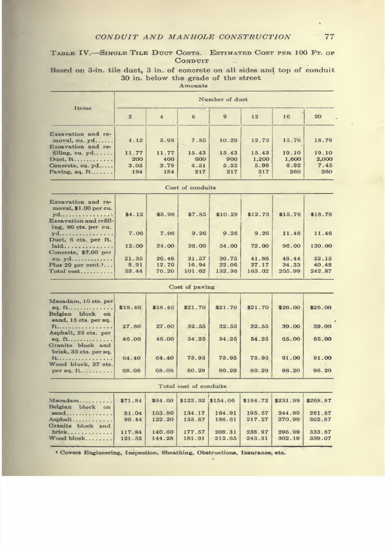
7/28/2019 Underground Trans 00 Me Yeu of t
http://slidepdf.com/reader/full/underground-trans-00-me-yeu-of-t 89/327
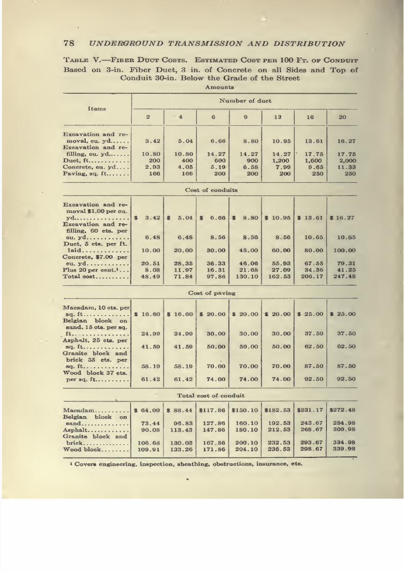
7/28/2019 Underground Trans 00 Me Yeu of t
http://slidepdf.com/reader/full/underground-trans-00-me-yeu-of-t 90/327
78 UNDERGROUND TRANSMISSION AND DISTRIBUTION
Table V. Fiber Duct Costs. Estimated Cost per 100 Ft. of Conduit
Based on 3-in. Fiber Duct, 3 in. of Concrete on all Sides and Top of
Conduit 30-in. Below the Grade of the Street
Amounts
Items
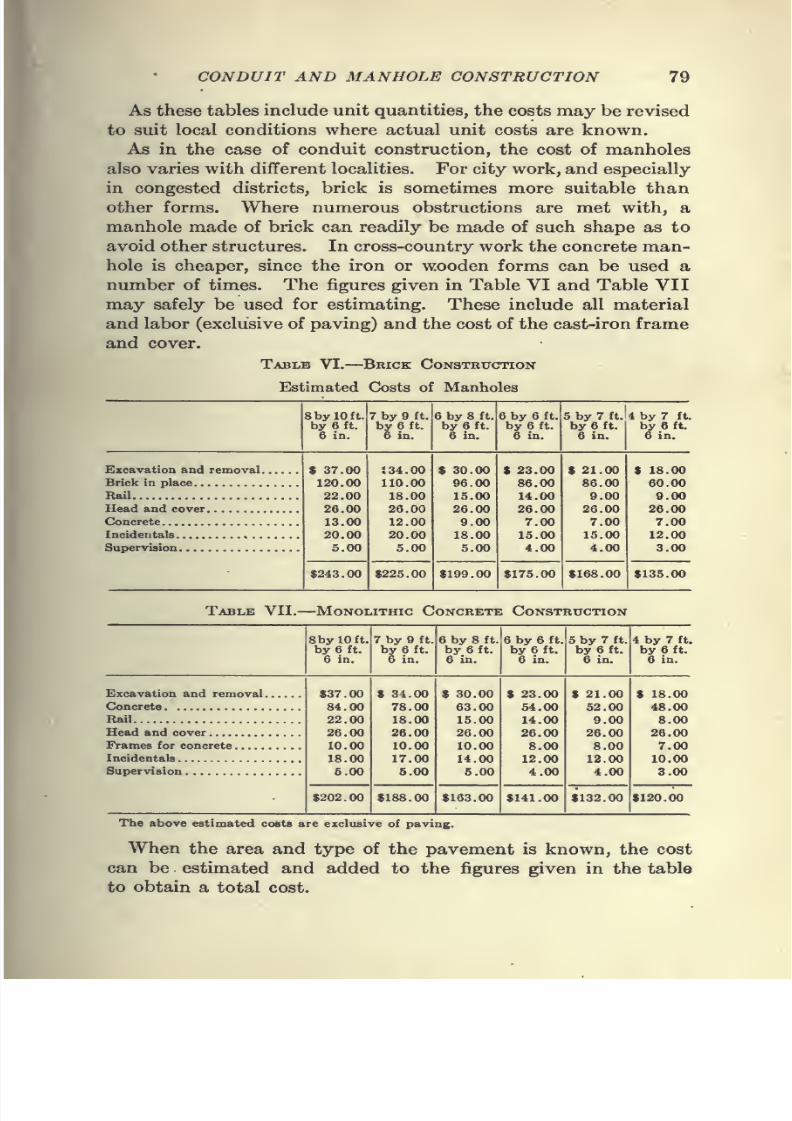
7/28/2019 Underground Trans 00 Me Yeu of t
http://slidepdf.com/reader/full/underground-trans-00-me-yeu-of-t 91/327
CONDUIT AND MANHOLE CONSTRUCTION 79
As these tables include unit quantities, the costs may be revised
to suit local conditions where actual unit costs are known.
As in the case of conduit construction, the cost of manholesalso varies with different localities. For city work, and especially
in congested districts, brick is sometimes more suitable than
other forms. Where numerous obstructions are met with, a
manhole made of brick can readily be made of such shape as to
avoid other structures. In cross-country work the concrete man-
hole is cheaper, since the iron or wooden forms can be used a
number of times. The figures given in Table VI and Table VII
maysafely be used for estimating. These include all material
and labor (exclusive of paving) and the cost of the cast-iron frame
and cover.
Table VI. Brick Construction
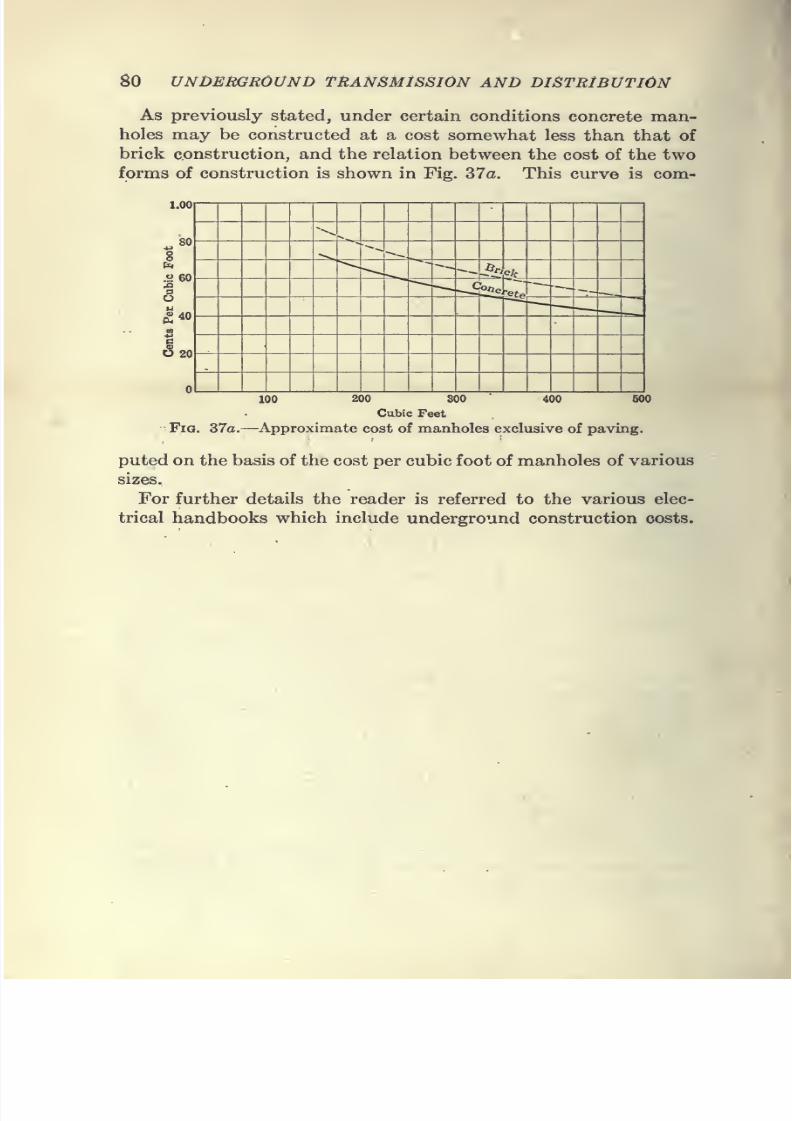
7/28/2019 Underground Trans 00 Me Yeu of t
http://slidepdf.com/reader/full/underground-trans-00-me-yeu-of-t 92/327
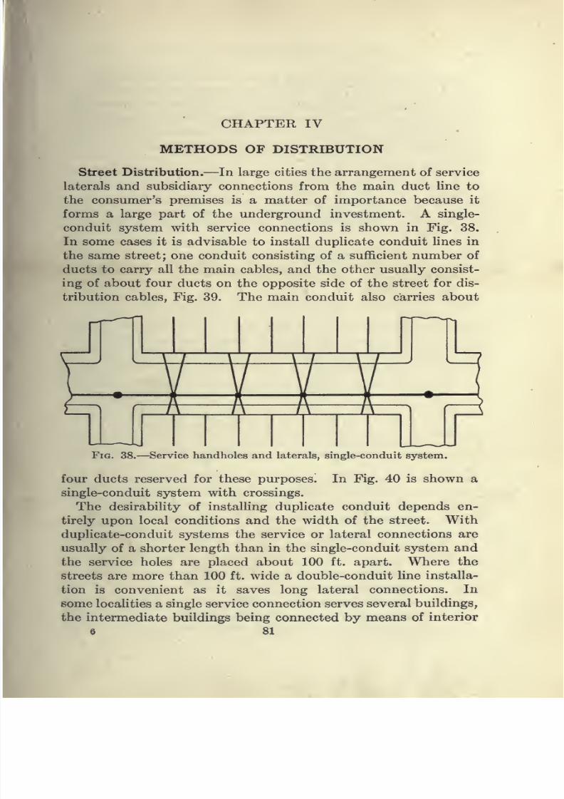
7/28/2019 Underground Trans 00 Me Yeu of t
http://slidepdf.com/reader/full/underground-trans-00-me-yeu-of-t 93/327
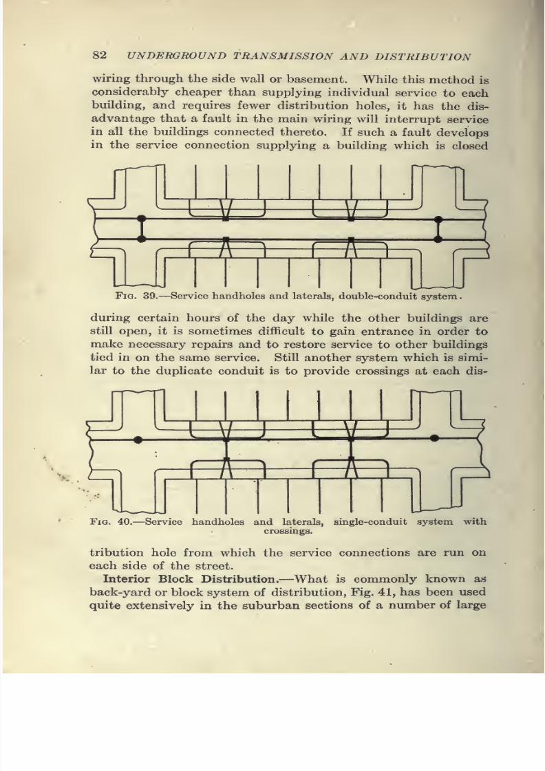
7/28/2019 Underground Trans 00 Me Yeu of t
http://slidepdf.com/reader/full/underground-trans-00-me-yeu-of-t 94/327
82 UNDERGROUND TRANSMISSION AND DISTRIBUTION
wiring through the side wall or basement. While this method is
considerably cheaper than supplying individual service to each
building, and requires fewer distribution holes, it has the dis-
advantage that a fault in the main wiring will interrupt service
in all the buildings connected thereto. If such a fault develops
in the service connection supplying a building which is closed
I\^^=E1R m^ < r~A~n r~/l~i
Fig. 39.—Service handholes and laterals, double-conduit system
.
duringcertain hours of the day while the other buildings are
still open, it is sometimes difficult to gain entrance in order to
make necessary repairs and to restore service to other buildings
tied in on the same service. Still another system which is simi-
lar to the duplicate conduit is to provide crossings at each dis-
/i
V 't
Fig. 40.—Service handholes and laterals, single-conduit system with
crossings.
tribution hole from which the service connections are run on
each side of the street.
Interior Block Distribution.—What is commonly known as
back-yard or block system of distribution, Fig. 41, has been used
quite extensively in the suburban sections of a number of large

7/28/2019 Underground Trans 00 Me Yeu of t
http://slidepdf.com/reader/full/underground-trans-00-me-yeu-of-t 95/327
METHODS OF DISTRIBUTION 83
cities. From the results obtained through its introduction
there seems to be good reason for the enthusiastic way in which
it has been taken up. Sofar
as appearances gothis plan pos-
sesses nearly all the advantages of the complete duct system and
the cost of reaching suburban houses with electrical service
in sections where the underground connections in streets would
be necessitated, is not much greater than would be entailed by
the straight overhead system. In the larger cities arrangements
have been made whereby the lighting companies have deeded
to them by the owner of the property the ground on which poles
maybe erected in the rear of houses, together with the right of
/'OTCNT'Ai. CAai.£3.A^c c/^ce//Ta ere.
Fig. 41.- -Plan of back-yard pole lines, with overhead-service connectionfed from main subway.
Jree access at all times, the company in return for this privilege
placing on the street an improved type of lamp post. In this
method of distribution the mains are rim to the back-yard linea^'
and the high-potential circuits are run underground to the tranSv^^
former manhole nearest the desired streets. From this point >\Xlow-potential circuits run to the street opposite the pole line
whence they branch and nm underground to the end pole on the
other side. The mains are then brought up through conduits
to the crossarm. Service connections are made to the main and
brought in to the rear of the house, thus relieving the front of the
property from overhead wires and service connections. The
pole line extends from block to block, depending on the number of
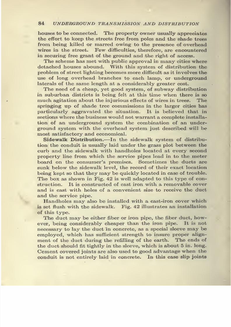
7/28/2019 Underground Trans 00 Me Yeu of t
http://slidepdf.com/reader/full/underground-trans-00-me-yeu-of-t 96/327
84 UNDERGROUND TRANSMISSION AND DISTRIBUTION
houses to be connected. The property owner usually appreciates
the effort to keep the streets free from poles and the shade trees
from being killed or marred owing to the presence of overheadwires in the street. Few difficulties, therefore, are encountered
in securing free grant of the ground and the right of access.
The scheme has met with public approval in many cities where
detached houses abound. With this system of distribution the
problem of street lighting becomes more difficult as it involves the
use of long overhead branches to each lamp, or underground
laterals of the same length at a considerably greater cost.
The need of a cheap, yet good system, of subway distributionin suburban districts is being felt at this time when there is so
much agitation about the injurious effects of wires in trees. The
springing up of shade tree commissions in the larger cities has
particularly aggravated the situation. It is believed that in
sections where the business would not warrant a complete installa-
tion of an underground system the combination of an under-
ground system with the overhead system just described will be
most satisfactory and economical.
Sidewalk Distribution.—In the sidewalk system of distribu-
tion the conduit is usually laid under the grass plot between the
curb and the sidewalk with handholes located at every second
property line from which the service pipes lead in to the meter
board on the consumer's premises. Sometimes the ducts are
sunk below the sidewalk level, the record of their exact location
being kept so that they may be quickly located in case of trouble.
The box as shown in Fig. 42 is well adapted to this type of con-
struction. It is constructed of cast iron with a removable cover
and is cast with holes of a convenient size to receive the duct
and the service pipe.
Handholes may also be installed with a cast-iron cover which
is set flush with the sidewalk. Fig. 42 illustrates an installation
of this type.
The duct may be either fiber or iron pipe, the fiber duct, how-
ever, being considerably cheaper than the iron pipe. It is not
necessary to lay the duct in concrete, as a special sleeve may be
employed, which has sufficient strength to insure proper ahgn-
ment of the duct during the refilling of the earth. The ends of
the duct should fit tightly in the sleeve, which is about 5 in. long.
Cement covered joints are also used to good advantage when the
conduit is not entirely laid in concrete. In this case slip joints
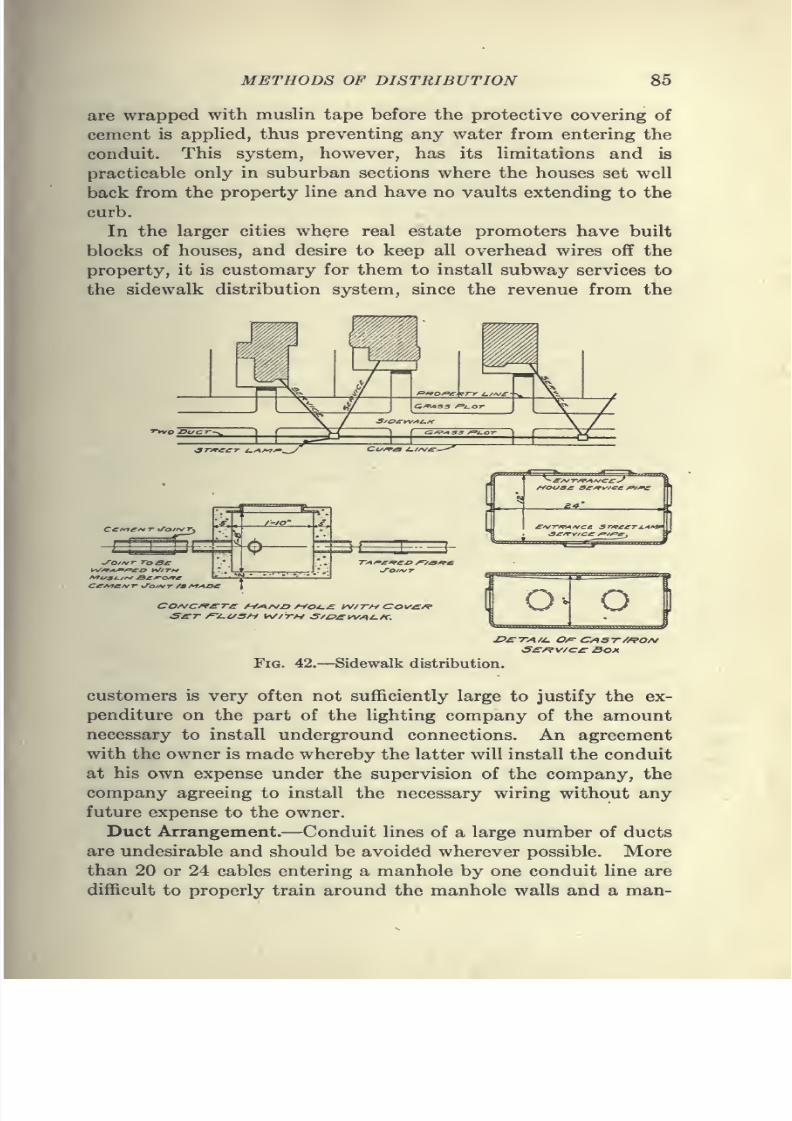
7/28/2019 Underground Trans 00 Me Yeu of t
http://slidepdf.com/reader/full/underground-trans-00-me-yeu-of-t 97/327
METHODS OF DISTRIBUTION 85
are wrapped with muslin tape before the protective covering of
cement is applied, thus preventing any water from entering the
conduit. This system, however, has its limitations and is
practicable only in suburban sections where the houses set well
back from the property line and have no vaults extending to the
curb.
In the larger cities where real estate promoters have built
blocks of houses, and desire to keep all overhead wires off the
property, it is customary for them to install subway services to
the sidewalk distribution system, since the revenue from the
<37'/rC£-T i^A/^^.
COA/C/^£rT^ A/>-^/VZ> /Vo^^ yV/7-/-f CO}/'^/^ o
S£f^v/C£ Boa
Fig. 42.—Sidewalk distribution.
customers is very often not sufficiently large to justify the ex-
penditure on the part of the lighting company of the amount
necessary to install underground connections. An agreement
with the owner is made whereby the latter will install the conduit
at his own expense under the supervision of the company, the
company agreeing to install the necessary wiring without any
future expense to the owner.
Duct Arrangement.—Conduit lines of a large number of ducts
are undesirable and should be avoided wherever possible. More
than 20 or 24 cables entering a manhole by one conduit line are
difficult to properly train around the manhole walls and a man-
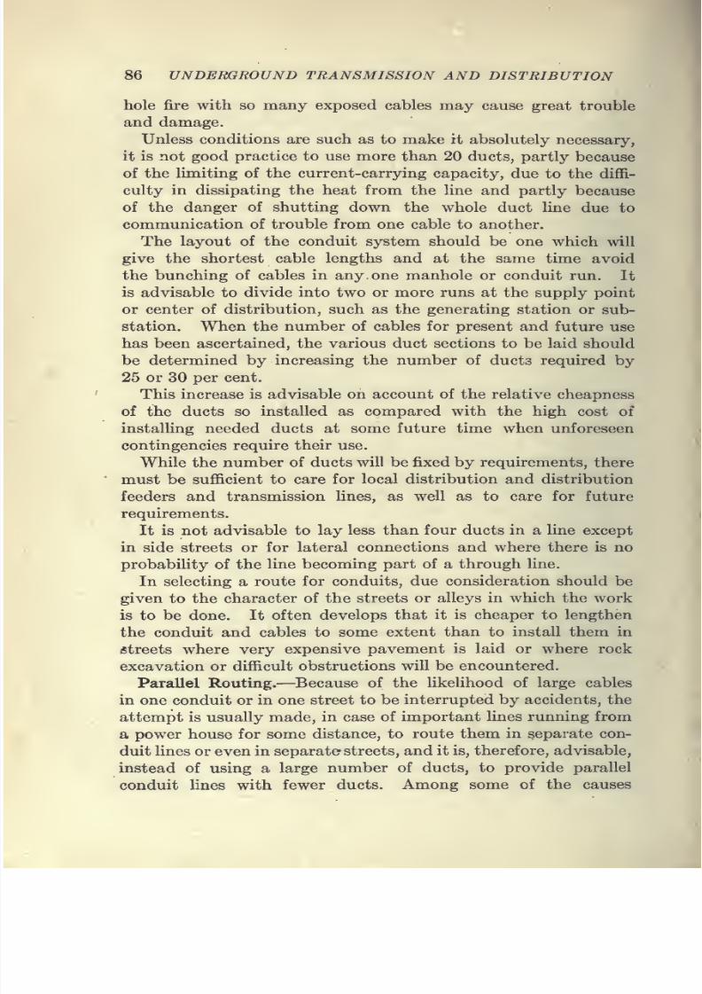
7/28/2019 Underground Trans 00 Me Yeu of t
http://slidepdf.com/reader/full/underground-trans-00-me-yeu-of-t 98/327
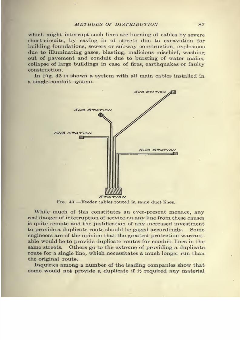
7/28/2019 Underground Trans 00 Me Yeu of t
http://slidepdf.com/reader/full/underground-trans-00-me-yeu-of-t 99/327
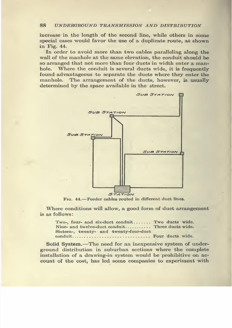
7/28/2019 Underground Trans 00 Me Yeu of t
http://slidepdf.com/reader/full/underground-trans-00-me-yeu-of-t 100/327
88 UNDERGROUND TRANSMISSION AND DISTRIBUTION
increase in the length of the second line, while others in some
special cases would favor the use of a duplicate route, as shown
in Fig. 44.
In order to avoid more than two cables paralleling along the
wall of the manhole at the same elevation, the conduit should be
so arranged that not more than four ducts in width enter a man-
hole. Where the conduit is several ducts wide, it is frequently
found advantageous to separate the ducts where they enter the
manhole. The arrangement of the ducts, however, is usually
determined by the space available in the street.
Sua Stat/ON
KSua Stat/oA/
^
Sue Stat/ON
mSTAT/Or^
Fig. 44.—Feeder cables routed in different duct lines.
Where conditions will allow, a good form of duct arrangement
is as follows
Two-, four- and six-duct conduit Two ducts wide.
Nine- and twelve-duct conduit. Three ducts wide.
Sixteen-, twenty- and twenty-four-duct
conduit Four ducts wide.
Solid System.—The need for an inexpensive system of under-
ground distribution in suburban sections where the complete
installation of a drawing-in system would be prohibitive on ac-
count of the cost, has led some companies to experiment with

7/28/2019 Underground Trans 00 Me Yeu of t
http://slidepdf.com/reader/full/underground-trans-00-me-yeu-of-t 101/327
METHODS OF DISTRIBUTION 89
a so-called "solid" system. One of the large illuminating com-
panies several years ago constructed a system which consisted
of fiber conduit laid directly in the ground without concrete,
but with a protective covering of "kyanized" planking resting
directly on the fiber tube.
The conductors consisted of ordinary line wire and were
arranged for three-wire distribution with the center or neutral
2 Plank
Compound
Fibre Conduit/ -%f'i-''-'
Omitted here "'
to show Jointing
Compound
INTERIOR VIEW OF BOX
SHOWING SERVICE CONNECTION
SECTION OF
FIBRE PIPE
Fig. 45.—Experimental solid system.
wire lying directly in the earth between the two outside con-
ductors.After laying the wire the fiber tubes were filled with an insulat-
ing compound. A complete installation of this type is shown in
Fig. 45. Service connections for customers were made by remov-
ing a short section of the covering and connecting service wires
to the mains, after which the joint was filled with compound and
7/28/2019 Underground Trans 00 Me Yeu of t
http://slidepdf.com/reader/full/underground-trans-00-me-yeu-of-t 102/327
90 UNDERGROUND TRANSMISSION AND DISTRIBUTION
the covering restored. The writer has been advised that this
system has been in service for about 8 years in suburban sections,
without showing any indication ofdeterioration,
and with nodisplacement of the compound during the summer months even
when laid on 5 per cent, grades.
The compound used in the installation shows a dielectric
strength of about 2,300 volts per in. and an expansion from solid
to liquid from 5 to 10 per cent. It is not affected by moisture
and has a flash test of about 700°r.
Service Connections.—Service or lateral connections from man-
holes to the consumers' premises are usually installed in wrought-
iron or steel pipe. The pipe should be thoroughly coated with
an asphaltic compound or other suitable protection to prevent
corrosion. Galvanized or sherardized pipe is sometimes used
in order to prolong the life of the service. In a number of
installations the iron pipe is used only in the street between the
manhole and the curb line where the traffic is heavy, and under
the sidewalk or on private property fiber pipe or some other form
of conduit may be used. It is customary in installing service
connections in a street which is about to be improved with a
permanent pavement, to install the laterals not only to present
consumers, but also to prospective customers, terminating the
pipe at the curb, a record being taken of the exact location in
order that the service may be continued to the consumers,
premises as the occasion requires.
For convenience in locating the pipe services, markers are fre-
quently placed in the sidewalk to fix the location.
These service markers consist of an iron rod which is driven
into the ground to the end of the pipe. The rod is capped with
a cast-iron plate which indicates the class of service.
Wooden plugs or metal caps are placed at the end of the pipe
in order to prevent earth or other material entering the pipe
when the excavation is being refilled.
It is frequently found necessary to install service pipes under
cement sidewalks or under highways, and since such installations
require a permit and the expenditure of considerable moneyfor restoration of the pavement, the use of a pipe-forcing jack
will be found economical. This jack is specially designed for
forcing pipe horizontally through the ground and may be used
advantageously where it is desired to install pipe under the con-
ditions mentioned above, or under railroad tracks or other cross-
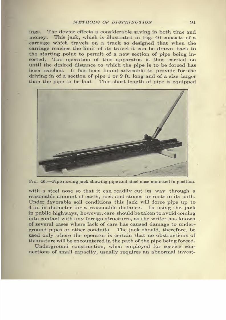
7/28/2019 Underground Trans 00 Me Yeu of t
http://slidepdf.com/reader/full/underground-trans-00-me-yeu-of-t 103/327
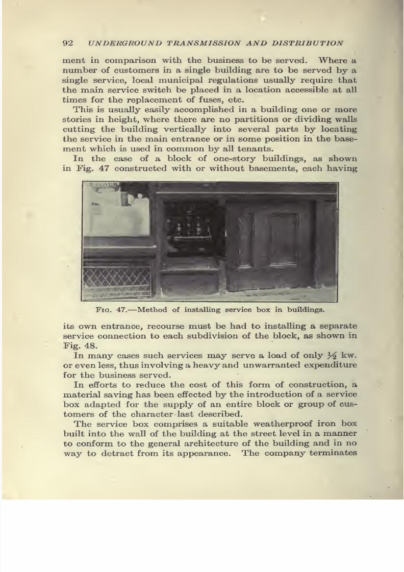
7/28/2019 Underground Trans 00 Me Yeu of t
http://slidepdf.com/reader/full/underground-trans-00-me-yeu-of-t 104/327
92 UNDERGROUND TRANSMISSION AND DISTRIBUTION
ment in comparison with the business to be served. Where a
number of customers in a single building are to be served by a
single service, local municipal regulations usually require that
the main service switch be placed in a location accessible at all
times for the replacement of fuses, etc.
This is usually easily accomplished in a building one or more
stories in height, where there are no partitions or dividing walls
cutting the building vertically into several parts by locating
the service in the main entrance or in some position in the base-
ment which is used in common by all tenants.
In the case of a block of one-story buildings, as shownin Fig. 47 constructed with or without basements, each having
Fig. 47.—Method of installing service box in buildings.
its own entrance, recourse must be had to installing a separate
service connection to each subdivision of the block, as shown in
Fig. 48.
In many cases such services may serve a load of only 3^ kw.
or even less, thus involving a heavy and unwarranted expenditure
for the business served.
In efforts to reduce the cost of this form of construction, a
material saving has been effected by the introduction of a service
box adapted for the supply of an entire block or group of cus-
tomers of the character last described.
The service box comprises a suitable weatherproof iron box
built into the wall of the building at the street level in a manner
to conform to the general architecture of the building and in no
way to detract from its appearance. The company terminates
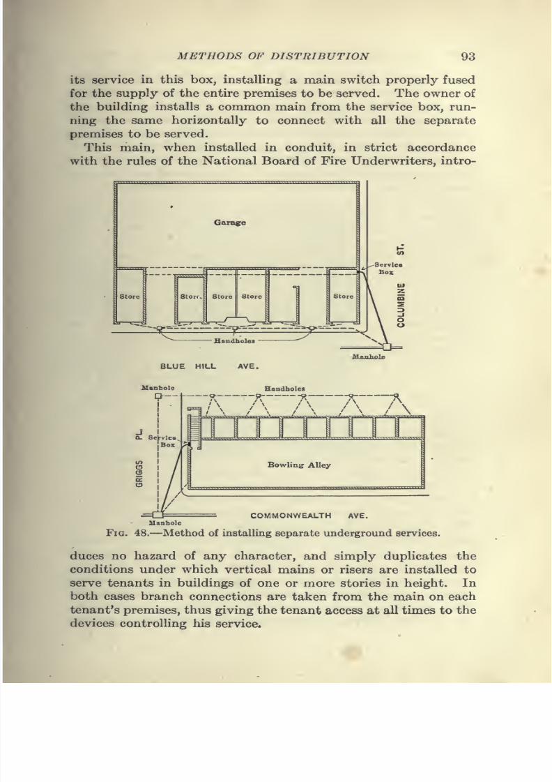
7/28/2019 Underground Trans 00 Me Yeu of t
http://slidepdf.com/reader/full/underground-trans-00-me-yeu-of-t 105/327
7/28/2019 Underground Trans 00 Me Yeu of t
http://slidepdf.com/reader/full/underground-trans-00-me-yeu-of-t 106/327
94 UNDERGROUND TRANSMISSION AND DISTRIBUTION
The main service box, located in the outside wall of the building,
is always accessible to the company's employees for re-fusing,
inspection, etc., and also to firemen or other municipal agents whomight desire to discontinue the service in the building in emer-
gencies. While the box is ordinarily locked, provision is madefor forcing the door without damage to the box itself.
Armored-cable System.—In Europe the installation of armored
cable is practically standard for all underground systems
supplying large, as well as small, service requirements.
These systems employ armored cables with or without lead
sheaths, laid directly in the ground or in insulated troughs
which are sometimes filled with compound as may best suit the
local conditions governing the installation.
Junction or distribution boxes are employed at the center
of distribution and service connections for customers are madeby means of wiped joints where lead-sheath cables are employed
and by connection boxes where non-leaded cables are used.
In the latter case these connection points are filled with com-
pound after the connection is completed. In this country the
armored-cable system has demonstrated its advantages for use
in cities where service requirements are of a difficult nature and
are subject to radical changes, and for residence streets where
there is a strip of land between the curb and the sidewalk line.
It can readily be installed in places where the drawing-in
system would be impossible owing to the necessity of passing
around large obstacles such as rocks, trees, etc.
The necessity for a safe and inexpensive conduit system in
many of the smaller cities or towns, and in the parks, playgrounds
and boulevards of larger cities, has brought about a great demand
for steel-tape cable. This cable is made in various sizes and is
adapted for any voltage. The conductors are insulated with a
rubber compound and taped. After the required number of
conductors has been laid and covered with jute and tape, a
lead sheath is applied and the whole served with jute. The
armor is then applied. This usually consists of two layers ofsteel tape over which is applied the asphalt and jute which
serves for the outside or final layer, as illustrated in Fig. 49.
Such construction is closely analogous to that of the standard
submarine cable and each layer or cover has its special function.
The outer jute covering protects the steel armor against the ac-
tion of water and chemicals and the steel tape affords mechanical
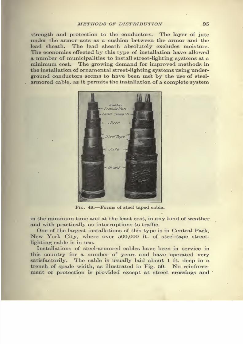
7/28/2019 Underground Trans 00 Me Yeu of t
http://slidepdf.com/reader/full/underground-trans-00-me-yeu-of-t 107/327
METHODS OF DISTRIBUTION 95
strength and protection to the conductors. The layer of jute
under the armor acts as a cushion between the armor and the
lead sheath. The lead sheath absolutely excludes moisture.The economies effected by this type of installation have allowed
a number of municipalities to install street-lighting systems at a
minimum cost. The growing demand for improved methods in
the installation of ornamental street-lighting systems using under-
ground conductors seems to have been met by the use of steel-
armored cable, as it permits the installation of a complete system
Fig. 49.—Forms of steel taped cable.
in the minimum time and at the least cost, in any kind of weather
and with practically no interruptions to traffic.
One of the largest installations of this type is in Central Park,
New York City, where over 500,000 ft. of steel-tape street-
lighting cable is in use.
Installations of steel-armored cables have been in service in
this country for a number of years and have operated very
satisfactorily. The cable is usually laid about 1 ft. deep in a
trench of spade width, as illustrated in Fig. 50. No reinforce-
ment or protection is provided except at street crossings and
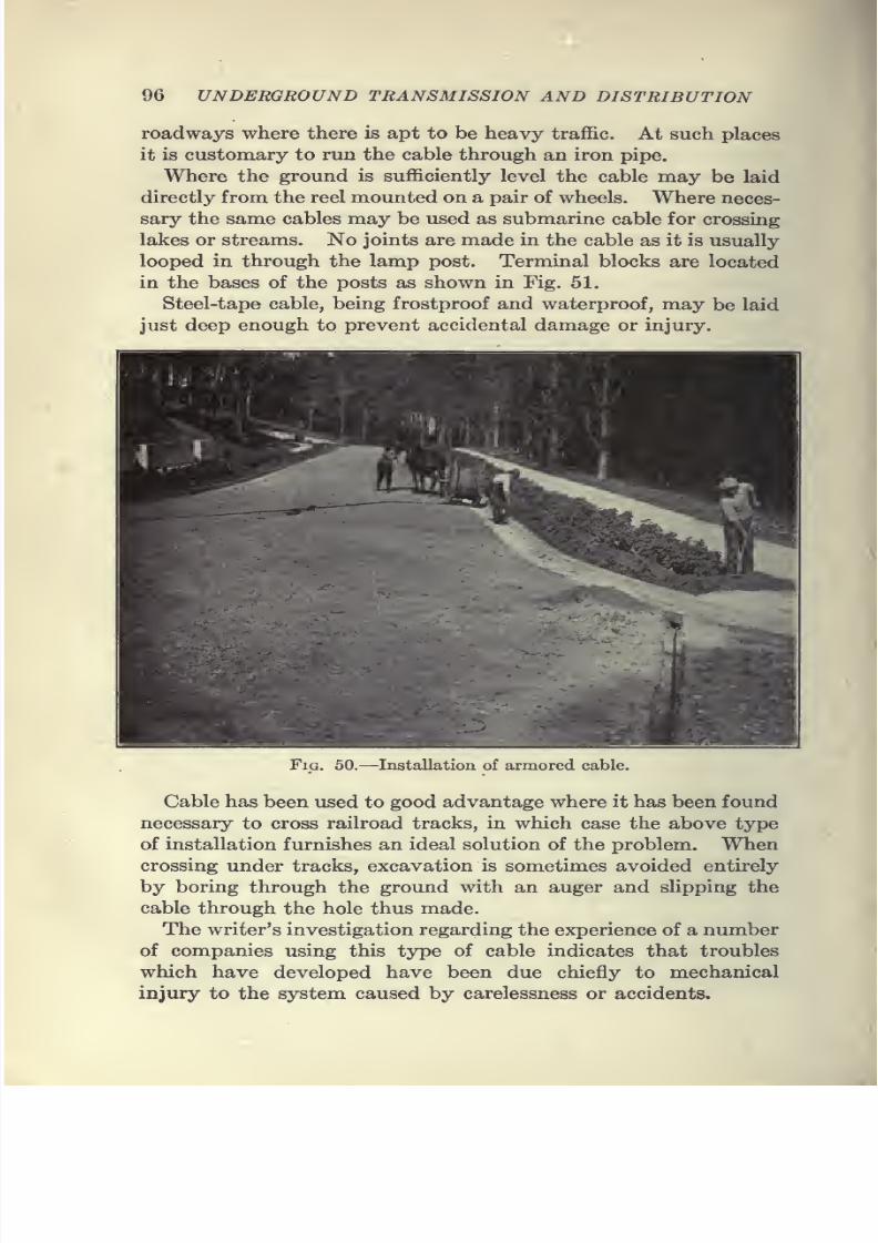
7/28/2019 Underground Trans 00 Me Yeu of t
http://slidepdf.com/reader/full/underground-trans-00-me-yeu-of-t 108/327
96 UNDERGROUND TRANSMISSION AND DISTRIBUTION
roadways where there is apt to be heavy traffic. At such places
it is customary to run the cable through an iron pipe.
Where the ground is sufficiently level the cable may be laid
directly from the reel mounted on a pair of wheels. Where neces-
sary the same cables may be used as submarine cable for crossing
lakes or streams. No joints are made in the cable as it is usually
looped in through the lamp post. Terminal blocks are located
in the bases of the posts as shown in Fig. 51.
Steel-tape cable, being frostproof and waterproof, may be laid
just deep enough to prevent accidental damage or injury.
Fig. 50.—Installation of armored cable.
Cable has been used to good advantage where it has been found
necessary to cross railroad tracks, in which case the above type
of installation furnishes an ideal solution of the problem. When
crossing under tracks, excavation is sometimes avoided entirely
by boring through the ground with an auger and slipping the
cable through the hole thus made.
The writer's investigation regarding the experience of a number
of companies using this type of cable indicates that troubles
which have developed have been due chiefly to mechanical
injury to the system caused by carelessness or accidents.
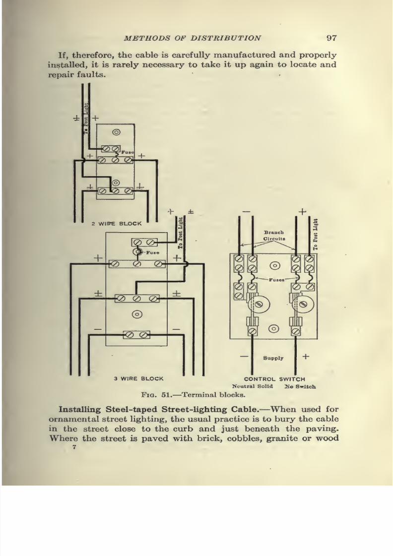
7/28/2019 Underground Trans 00 Me Yeu of t
http://slidepdf.com/reader/full/underground-trans-00-me-yeu-of-t 109/327
METHODS OF DISTRIBUTION 97
If, therefore, the cable is carefully manufactured and properly
installed, it is rarely necessary to take it up again to locate and
repair faults.
3 WIRE BLOCK
+
m ® m
Supply
CONTROL SWITCH
Neutral Solid 3So Switch
Fig. 51.—Terminal blocks.
Installing Steel-taped Street-lighting Cable.—When used for
ornamental street lighting, the usual practice is to bury the cable
in the street close to the curb and just beneath the paving.
Where the street is paved with brick, cobbles, granite or wood
7
7/28/2019 Underground Trans 00 Me Yeu of t
http://slidepdf.com/reader/full/underground-trans-00-me-yeu-of-t 110/327
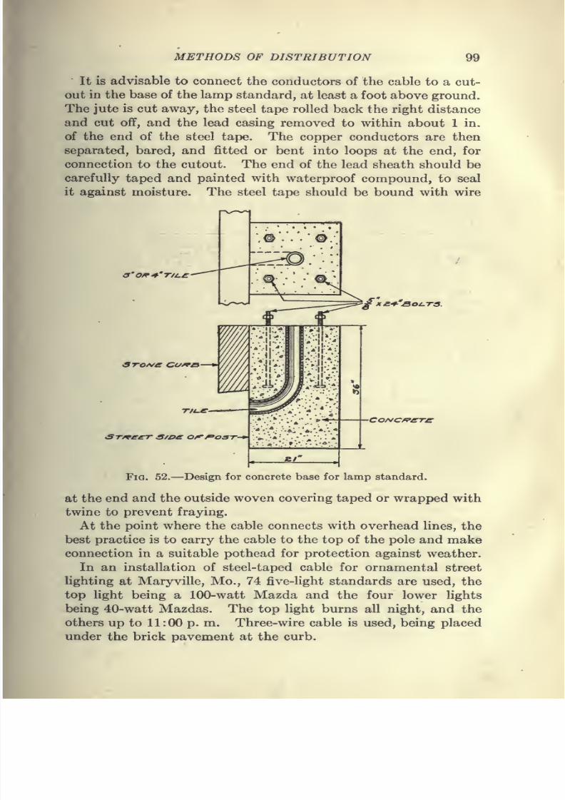
7/28/2019 Underground Trans 00 Me Yeu of t
http://slidepdf.com/reader/full/underground-trans-00-me-yeu-of-t 111/327
METHODS OF DISTRIBUTION 99
It is advisable to connect the conductors of the cable to a cut-
out in the base of the lamp standard, at least a foot above ground.
The jute is cut away, the steel tape rolled back the right distanceand cut off, and the lead casing removed to within about 1 in.
of the end of the steel tape. The copper conductors are then
separated, bared, and fitted or bent into loops at the end, for
connection to the cutout. The end of the lead sheath should be
carefully taped and painted with waterproof compound, to seal
it against moisture. The steel tape should be bound with wire
3'Off^'T/i.S
3TO/sfe CC/^B
ST/recr s/oe o^^ost-^
'£XS-^'SOCTS.
CoAfC/r'/rre
Fig. 52.—Design for concrete base for lamp standard.
at the end and the outside woven covering taped or wrapped with
twine to prevent fraying.
At the point where the cable connects with overhead lines, the
best practice is to carry the cable to the top of the pole and make
connectionin
a suitable potheadfor
protection against weather.In an installation of steel-taped cable for ornamental street
lighting at Maryville, Mo., 74 five-light standards are used, the
top light being a 100-watt Mazda and the four lower lights
being 40-watt Mazdas. The top light burns all night, and the
others up to 11 : 00 p. m. Three-wire cable is used, being placed
imder the brick pavement at the curb.

7/28/2019 Underground Trans 00 Me Yeu of t
http://slidepdf.com/reader/full/underground-trans-00-me-yeu-of-t 112/327
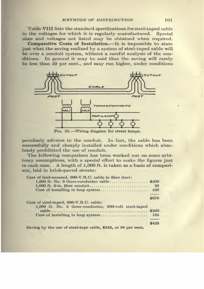
7/28/2019 Underground Trans 00 Me Yeu of t
http://slidepdf.com/reader/full/underground-trans-00-me-yeu-of-t 113/327
METHODS OF DISTRIBUTION 101
Table VIII lists the standard specifications forsteel-taped cable
in the voltages for which it is regularly manufactured. Special
sizes and voltages not listed may be obtained when required.Comparative Costs of Installation.—It is impossible to state
just what the saving realized by a system of steel-taped cable will
be over a conduit system, without a careful analysis of the con-
ditions. In general it may be said that the saving will rarely
be less than 30 per cent., and may run higher, under conditions
Cutout CUTOUT
CABl.e
f=>OST ^^ST
NO.
Tf?A/\fS^O^f>yt£^S
TOP /-AM/'y
§rrv^Fig. 53.—Wiring diagram for street lamps.
peculiarly adverse to the conduit. In fact, the cable has been
successfully and cheaply installed under conditions which abso-
lutely prohibited the use of conduit.
The following comparison has been worked out on some arbi-
trary assumptions, with a special effort to make the figures just
in each case. A length of 1,000 ft. is taken as a basis of compari-
son, laid in brick-paved streets:
Cost of lead-encased, 600-V.R.C. cable in fiber duct:
1,000 ft. No. 6 three-conductor cable $200
1,000 ft. 2-in. fiber conduit 50
Cost of installing in loop system 420
$670
Cost of steel-taped, 600-V.R.C. cable:
1,000 ft. No. 6 three-conductor, 600-volt steel-taped
cable $260
Cost of installing in loop system 165
$425
Saving by the use of steel-tape cable, $245, or 36 per cent.
7/28/2019 Underground Trans 00 Me Yeu of t
http://slidepdf.com/reader/full/underground-trans-00-me-yeu-of-t 114/327
CHAPTER V
CABLES
General.—In present-day practice of underground construction
lead-covered insulated cables are used almost exclusively. The
three essential members of such a cable are: The conductor itself,
the wall of insulating material and the outer protective covering,and they will be considered in the order named.
Tenninology.—The following definitions relating to wire and
cables are based on Bulletin No. 37, issued by the Bureau of
Standards, January, 1915.
Wires and Cables
Wire.—A slender rod or filament of drawn metal.
Conductor.—A wire, a combination of wires not insulated from one an-
other, suitable for carrying a single electric current.
Stranded Conductor.—A conductor composed of a group of wires, or of
any combination of groups of wires.
Cable.— (1) A stranded conductor (single-conductor cable) ; or (2) a com-
bination of conductors insulated from one another (multiple-conductor
cable).
Strand.—One of the wires or groups of wires of any stranded conductor.
Stranded Wire.—A group of small wires used as a single wire.
Cord.—-A small and very flexible cable, substantially insulated to with-
stand wear.
Concentric Strand.—A strand composed of a central cord surrounded by
one or more layers of helically laid wires or groups of wires.
Duplex Cable.—Two insulated conductor cables, twisted together.
Twin Cable.—Two insulated single-conductor cables, laid parallel, hav-
ing a common covering.
Triplex Cable.—Three insulated, single-conductor cables twisted together.
Twisted Pair.—Two small insulated conductors twisted together without
a common covering.
Twin Wire.—Two small insulated conductors laidparallel,
having a com-mon covering.
Conductor.—Theoretically the transmission of electricity
through any substance is a matter of degree; practically we may
make a distinction between conducting and insulating materials.
102
7/28/2019 Underground Trans 00 Me Yeu of t
http://slidepdf.com/reader/full/underground-trans-00-me-yeu-of-t 115/327
r
CABLES 103
The following table gives a list of materials approximately ar-
ranged in order of their conducting powers.
Conductors Non-conductors or insulators
All metals , .
.
Dry air Ebonite
Well-burned charcoal. Shellac Gutta percha
Plumbago Paraffine India rubber
Acid solutions Rosins Silk
Metallic ores Sulphur Dry paper
Living vegetable substances Wax Dry leather
Moist earth Glass Porcelain
Water Mica Oils
The conducting power of any substance depends largely upon
its physical state, and the conductivity of all substances materi-
ally alters with a change of temperature.
The general trend of this change in conductivity with rising
temperature is toward a decrease with metals and toward an
increase with other substances.
In commercial transmission of electricity we are limited to
the use of three metals: copper, iron and aluminum, although
abnormal conditions of late have added zinc in certain countries.
Copper ranks first in importance, with aluminum next, and iron
last, and whether or not the use of zinc will survive after normal
conditions are restored appears uncertain. Pure copper, in
addition to its high conductivity, possesses many other physical
properties of special value in cable work.
Its strength, malleability and cost in comparison with that of
other metals makes it an ideal material for cable work. The
malleability, ductility, tensile strength and electrical conduc-
tivity of copper are somewhat modified by impurities. These,
when present, usually are of one or more elements such as bis-
muth, arsenic, antimony, sulphur, etc. ; however, the electrolytic
wire bars so largely used in the manufacture of wires and cables
for electrical purposes are almost pure.
Refining of copper and its separation from the multitude of
alloying metals is a complex metallurgical process, but a very
necessary one. Even traces of other metals affect the con-
ductivity'^ to a remarkable degree, as the following table will
show:
7/28/2019 Underground Trans 00 Me Yeu of t
http://slidepdf.com/reader/full/underground-trans-00-me-yeu-of-t 116/327
104 UNDERGROUND TRANSMISSION AND DISTRIBUTION
Element ^^'^ cent, present Per cent, oon-in copper ductivity
Carbon 0.05 77.87
Sulphur 0. 18 92.08
Arsenic 0.10 73.89
Silver 1.22 90.34
Tin 1.33 50.44
Aluminum 0. 10 86.49
Copper enters readily into combination with the constituents
of rubber insulation and must be coated with a protective such
as tin, which is not easily attacked.
Copper is easily soluble in nitric acid, aqua regia and strong
boiling sulphuric acid; and in diluted sulphuric acid, when ex-
posed to the air, it dissolves slowly.
The tensile strength of annealed copper is usually about 30,000
lb. per sq. in., but when it is hard-drawn or medium hard-drawn,
its strength is increased to 50,000 and 65,000 lb., depending upon
the size of the wire.
Table IX gives the average values of breaking weight for
various sizes.
Table IX.-
7/28/2019 Underground Trans 00 Me Yeu of t
http://slidepdf.com/reader/full/underground-trans-00-me-yeu-of-t 117/327
I
CABLES 106
at 500°F. it is about 16 per cent, and above SOO^F. it is so great
as to make the metal almost useless.
As theconductivity of
any onewire will, in
general, differ
from that of any other, it is necessary in comparing or specifying
wires to refer to some standard.
The present practice in copper specifications for cable work,
is to refer to the standardization rules of A.I.E.E. of which the
following shall be taken as normal values of standard annealed
copper.
1. At a temperature of 20°C., the resistance of a wire of standard annealed
copper, 1 meter in length, and of a uniform section of 1 sq. mm. is J^g ohm =0.017241 .... ohm.
2. At a temperature of 20°C., the density of standard annealed copper is
8.89 grams per c.c.
3. At a temperature of 20°C., the "constant mass" temperature coeffi-
cient of resistance of standard annealed copper measured between two poten-
tial points rigidly fixed to the wire is 0.00393 = ^^54-45 • • • . per degree
Centigrade.
4. As a consequence, it follows from (1) and (2) that, at a temperature of
20°C., the resistance of a wire of standard annealed copper of uniform sec-
tion, 1 meter in length, and weighing 1 gram, is (J^s) X 8.89 = 0.15328 . .
.
ohm.
Table X gives a comparison of wire gages of the Brown &Sharpe, or American ("B. & S."), the Birmingham (B.W.G.)
and the British Standard (S.W.G.) wire gages.
In Table XI is given the diameter, weight and resistance of
copper wires.
The following Table XII gives data regarding standard con-
centric strands of different sizes of cable, as recommended by
the General Electric Co.
The area of the finished cable is that of the individual wires
cut at right angles to their axes, when laid straight, multiplied by
the number of wires in the cables. Special attention is called
to this point, since in some, cases the area of the individual wires
is figured as if cut after twisting, i.e., on the "bias," thus using a
figure larger than the actual area of the finished conductor, and
results in a cable having less copper than if the area was correctly
figured.
Insulating Wall.—The principal materials used for insulating
power cables are rubber, saturated-paper tapes, varnished cam-
bric or cloth and graded insulation usually consisting of a
combination of the foregoing.
7/28/2019 Underground Trans 00 Me Yeu of t
http://slidepdf.com/reader/full/underground-trans-00-me-yeu-of-t 118/327
106 UNDERGROUND TRANSMISSION AND DISTRIBUTION
X
«^1•O 03 O
:la-§
•3 .^
pa .a
g ea OS
« go,
•43 StS
pa 051-132
Sb5PQJ3
^ 03 oj
•n-o
o © «
00OM05OW<D-^ N ffl 1-1M <* 00 O) •-< «00NU5»O)tJI03 lO CO t- 05O "-I C<5 * lO t» CX) 05O 1-1 CO t)i lO t»00 OJ O MM <N IN (M (N CC TO C<5 MM M W CO t)i M< ^ Tf t(i tJi Tt< tJi U5 lO
oooooooo oooooooo ooooo'o'o
gSSQPSSS P'ooo'Oicioitj ooooicoooO'oicooo 'ot>-u»iot>.(NenN lOOioiot^Oio03O "O 1-1 05 1" "5 CO OCOO'CCOiMi-iO 03 OS h-W5 "5 «!
S2!W COC^ C>) (N (N (M -H rt ^ ^ ,-1 ,-. ,-1 OOOOOOOOOOOOOO oooooooo OOOOOOO
oooooooo OOOOOOOO OOOOOOO
OOOOOOOO O T)< 00 to •* CDMO (N •* CO 00OM 00
OOOOOOOO OOOOOOOO OOOOOOO
OJI>JiO<NOO'OlNO 00CO'«J<C0NO»00 t^iO'*S-*COCON(NC4(N 1-1 —c --^ 1-1 ^O O OOOOOOOOOO OOOOOOOO OOOOOOOOOOO OOOOOOOO OOO
O OS CO CD U) t>. O OCO00O>"^COiCi-<o>O "5 r-< 00 "n iM o t-
SCO CO (N M <N (N r-i
OOOOOOO
•^OiJicOCOCOiOOO0!C^CD(NPO>0!0lO Tf IN ^O 00W t»
oooooooo
O -HQ "5 CO CO Tl<
CO CDO * O! lO 1-1
CD m lo T)< CO CO CO
OOOOOOOO OOOOOOOO OOOOOOO
iraOOOt-COOOOr)! i-iC0NOO(N0000 •'foOOiOO'COb"i—iTjii—'00»OCOO ^^»--'^.«-i^-*-. —
.— *- ^
•gi 3" CO CO C^ (N (N IN ,-i^^_i.ooooooooOOOOOOOO
oooooooo OOOOOOOoooooooo OOOOOOO
80 CO 00 CO t-o o•c CD CD 00 cj> rt oq ,. ,
Tf<00000-Hi-< »-<i-i
i005C<llNiOt^(NiOCO * CO r~ 00 05 1-1 (N
rtrt^,-iMlN
oooooooo oooooooo
oooooooo oooooooo-"~""~"'^iO00 iiji O OiiC CO C^ lO 00
C^C<1CQCV)C^»-I^i-1
•OOOOO oooooooo OOOOOOOO
S'*N P <N 00 •*p
cOCOOt^-^iNO
lO-^TfTficOCOCOCO (N C^ (N (N1-1 1-1
rt1-1
OOcOTjilNOfNMiCOiNrioosoot^com
1-HrHrtOOOOOoooooooo OOOOOOOO OOOOOOOO
8'<J(iOOOO -^OlOOOCOOiOOOiOlN00-*O 00 X5 CON O 00 CO*
U5 * •* CO CO CO M <N M Cv) (N 1-1 rt w•*O<SiOC0N"500C0(NO0!00t>-c0"0l-f^rHOOOOO
OOOOOO OOOOOOOO OOOOOOOO
•OOpTfOCOO CO IN 1-1 •* IN 00 C3J CO_ - JCOOOOOCO•OCOOOi-^^OS• 00 — CDO CO (N 00• U5 >r5 T)< •* CO CO IN
cDTficoOJOC^t"*h-OTfi-ilNTtoO'^lO oa o 00 o Tt< N rfINMC<ll-ll-lrHrtrt
•OOOOOOO ooooooooi-iOOOOOOOoooddddo
8iOu000>OO>CO lOt^COOOOOCO-<O CO C^ -- CO CO (N CO lO f^ IN t^ C^ 00OS CO CO 03 CD COO 00 O Tf IN O OS !> CD TfIf* 1* CO CO CO COM (N IN ffg IN -H rt -H rH
oioioiopowo>00>O^OC^(Nt(<CO IN O OS 00 1^ CD lOrtrtrtOOOOO
OOOOOOOO OOOOOOOO oooooooo
OOOOOOO'^pooooopopooN CO 'It U5 CO t» 0005 O f-lN CO^ UO CO t^
7/28/2019 Underground Trans 00 Me Yeu of t
http://slidepdf.com/reader/full/underground-trans-00-me-yeu-of-t 119/327
CABLES 107
Table XI. Diameter, Weight and Resistance op Copper Wire
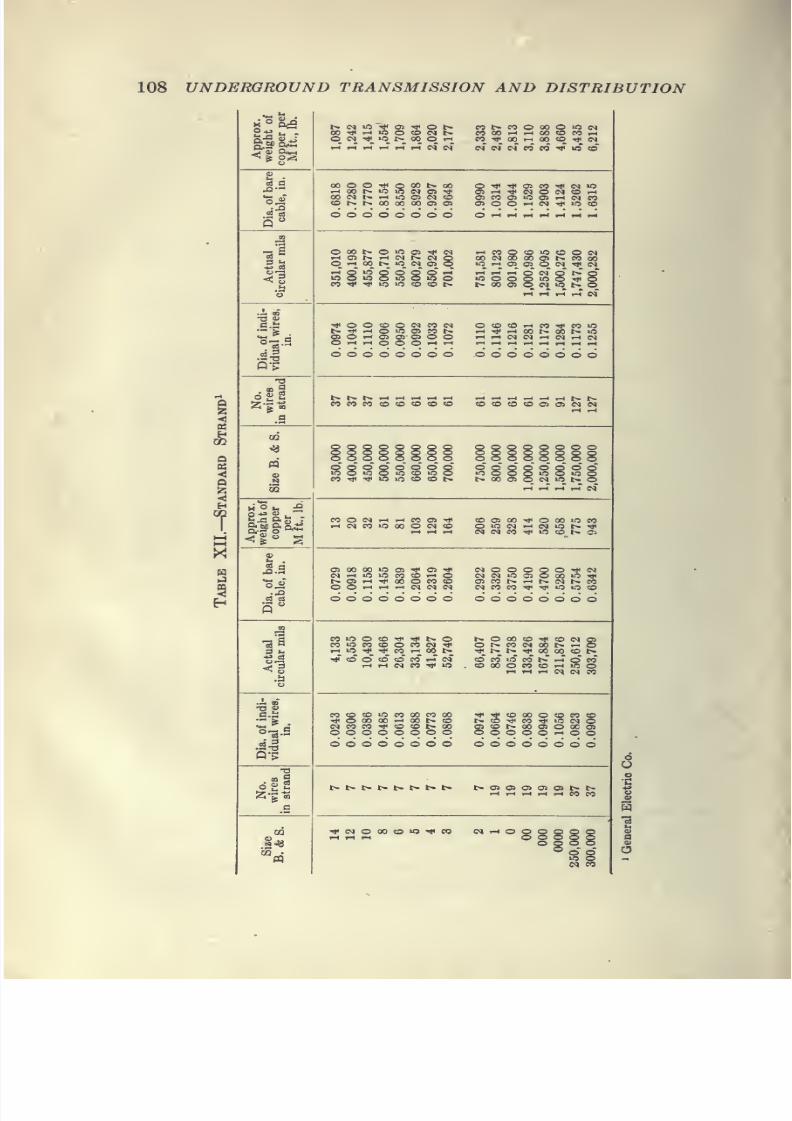
7/28/2019 Underground Trans 00 Me Yeu of t
http://slidepdf.com/reader/full/underground-trans-00-me-yeu-of-t 120/327
108 UNDERGROUND TRANSMISSION AND DISTRIBUTION
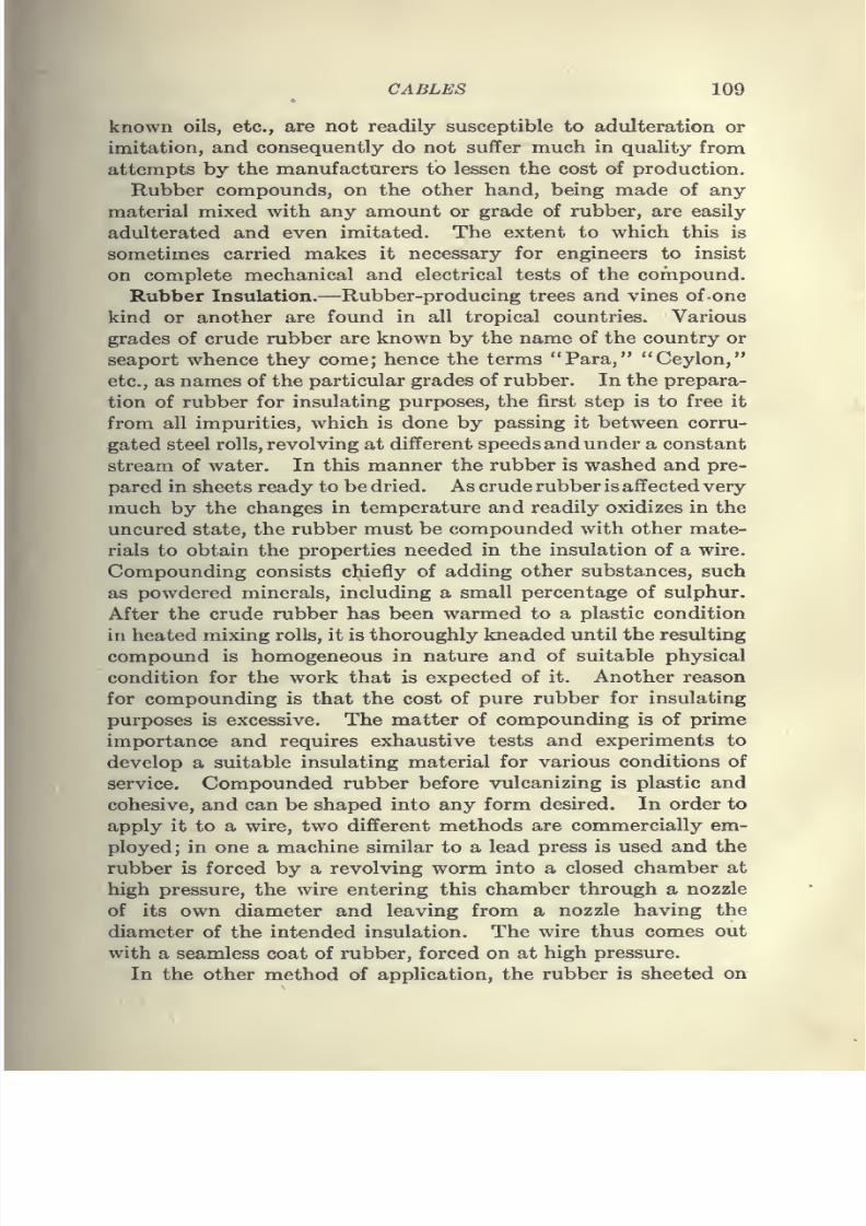
7/28/2019 Underground Trans 00 Me Yeu of t
http://slidepdf.com/reader/full/underground-trans-00-me-yeu-of-t 121/327
CABLES 109
known oils, etc., are not readily susceptible to adulteration or
imitation, and consequently do not suffer much in quality from
attempts by the manufacturers to lessen the cost of production.
Rubber compounds, on the other hand, being made of any
material mixed with any amount or grade of rubber, are easily
adulterated and even imitated. The extent to which this is
sometimes carried makes it necessary for engineers to insist
on complete mechanical and electrical tests of the compound.
Rubber Insulation.—Rubber-producing trees and vines of-one
kind or another are found in all tropical countries. Various
grades of crude rubber are known by the name of the country or
seaport whence they come; hence the terms "Para," "Ceylon,"
etc., as names of the particular grades of rubber. In the prepara-
tion of rubber for insulating purposes, the first step is to free it
from all impurities, which is done by passing it between corru-
gated steel rolls, revolving at different speeds andunder a constant
stream of water. In this manner the rubber is washed and pre-
pared in sheets ready to be dried. As crude rubber is affected very
much by the changes in temperature and readily oxidizes in theuncured state, the rubber must be compounded with other mate-
rials to obtain the properties needed in the insulation of a wire.
Compounding consists chiefly of adding other substances, such
as powdered minerals, including a small percentage of sulphur.
After the crude rubber has been warmed to a plastic condition
in heated mixing rolls, it is thoroughly kneaded until the resulting
compound is homogeneous in nature and of suitable physical
condition for the work that is expected ofit.
Another reasonfor compounding is that the cost of pure rubber for insulating
purposes is excessive. The matter of compounding is of prime
importance and requires exhaustive tests and experiments to
develop a suitable insulating material for various conditions of
service. Compounded rubber before vulcanizing is plastic and
cohesive, and can be shaped into any form desired. In order to
apply it to a wire, two different methods are commercially em-
ployed; in one a machine similar to a lead press is used and the
rubber is forced by a revolving worm into a closed chamber at
high pressure, the wire entering this chamber through a nozzle
of its own diameter and leaving from a nozzle having the
diameter of the intended insulation. The wire thus comes out
with a seamless coat of rubber, forced on at high pressure.
In the other method of application, the rubber is sheeted on
7/28/2019 Underground Trans 00 Me Yeu of t
http://slidepdf.com/reader/full/underground-trans-00-me-yeu-of-t 122/327
110 UNDERGROUND TRANSMISSION AND DISTRIBUTION
a calendar having heavy smooth rolls, and the sheets thus made
are cut into narrow strips, the width and thickness of which
depend on the wire to be insulated, and the number of covers to
be used. By this method a wire is passed between two or more
curved rolls, running in tangent to each other. As the wire
enters each pair of rolls, strips of rubber enter at the same
time and the grooves form a uniform thickness of rubber about
the wires, the edges meeting in a continuous seam.
Surplus rubber is cut off the rolls and the seams, being made
between two pieces of the same unvulcanized cohesive stock
under pressure, become invisible in the wire, and can be deter-
mined only by a ridge along the insulation.
In the process of vulcanization, the rubber at the seams is
kneaded together so that the rubber at this point is as dense and
homogeneous as at any other part of the insulation.
Fig. 54.—Crude rubber.
Good rubber compound will last indefinitely in pure or salt
water, but if the water contains sewage, acids, oils, or other
destroying agents, it will have a short life unless protected withsome outer covering, such as a lead sheath.
In order to vulcanize rubber compounds, they are subjected
to temperatures somewhat above the melting point of sulphur,
which temperatures are usually obtained by steam under pres-
sure. This operation causes the sulphur in the compound to
chemically unite with the rubber and other ingredients with the
result that the rubber is no longer plastic; it becomes firm, strong,
elastic, susceptible neither to heat nor cold, and not readilyaffected at ordinary temperatures by the usual solvents of unvul-
canized rubber. Its mechanical properties depend considerably
on the time and temperature of vulcanization, as well as the
amount of sulphur used. In producing high-grade insulation,
proper vulcanization is fully as important as the selection of the
crude materials. Rubber insulation is usually protected by a
7/28/2019 Underground Trans 00 Me Yeu of t
http://slidepdf.com/reader/full/underground-trans-00-me-yeu-of-t 123/327
CABLES 111
winding of tape or braid, or a tape and one or more braids,
depending ujpon the class of service for which it is to be used.
When used for station workit is
sometimes provided with anouter braid of asbestos or other form of flameproof covering, to
serve as a fire protection. "When installed in underground con-
duits where it is subjected to the severest conditions, it should be
covered with a lead sheath.
Paper Insulation.—The use of paper-insulated cables for elec-
tric light and power work is rapidly increasing, and when prop-
erly constructed and installed such cables give excellent service.
Various kinds of paper have been used for cable insulation;
the extremes of quality are represented by that made from wood
pulp, which is the poorest, and that made from manila rope fiber,
which is the best. Between these extremes there are combina-
tions of wood pulp with jute, jute with manila fiber and wood
pulp, jute and manila fiber. A paper containing any appre-
ciable amount of pulp will "felt down" when saturated with
insulating oils. In other words, the fibers of the paper stand
up before saturation, giving a thickness of insulating wall, which
is greatly diminished during impregnation; because of this "felt-
ing down" even the most tightly wound insulations composed of
pulp paper, will be found quite loose after saturation. Wood
fiber or pulp paper is apt to be injured during the drying process
to which it is subjected before impregnation, and it has been
known to rot badly under the influence of certain ofthe substances
used in the impregnating solution. A paper containing any
appreciable amount of jute, either alone or in combination with
pulp and manila, will have practically all the disadvantages of
pulp paper and in addition the jute will saturate very slowly,
which sometimes may result in an unevenly saturated cable.
Manila-rope paper is free from this objection and its structure is
hard, close and even. It may be dried perfectly without loss
of strength aud will not rot under the action of properly prepared
impregnating oils.
Manila-rope paper of the very highest grade should be used
in all paper-insulated cable. The impregnating oils now used
by the majority of cable manufacturers consist of solutions of
rosin and rosin oil, and solutions of rosin and petroleum oil, or
a mixture of these solutions. Commercial rosin, as ordinarily
found on the market, is a mixture of what may be termed rosin,
some undecomposed turpentine gum, some water, acetic acid and
7/28/2019 Underground Trans 00 Me Yeu of t
http://slidepdf.com/reader/full/underground-trans-00-me-yeu-of-t 124/327
112 UNDERGROUND TRANSMISSION AND DISTRIBUTION
butyric acid, together with light turpentine naphthas and turpen-
tine. These impurities are found to a much larger extent in
second-run rosin oil. The method of preparing rosin oil for im-
pregnation varies with different manufacturers in accordance
with their particular formula, and the lack of uniformity in
commercial rosin oil requires that great care be taken in the
preparation of the oil for insulating purposes. The dielectric
value of paper, depends not only on the quality of the paper and
the manner of applying it to the conductor, but to a great extent
upon the composition of the insulating compound. Increasing
the fluidity of the compound within certain limits will improvethe puncture test and will increase the flexibility of the cable, but
will reduce the megohm tests and vice versa. A dense, thick
compound will result in a very stiff cable, but one having a higher
insulation resistance. The insulation of such a cable is apt to
crack or break if bent at a low temperature. In the preparation
of paper-insulated cables automatic machines are employed to
wind narrow strips of paper spirally around the conductors
until there are enough layers to secure the requisite dielectric
strength. If the cable is to consist of two or more conductors,
the necessary number of conductors, each encased in its wrapping
of paper, are laid up together and the whole encased in an outer
wrapping, or belt, composed of additional layers of paper.
Before the outer wrapping of paper is applied, the cable is
filled with jute laterals to make the whole cylindrical. For
high-tension cables some manufacturers use a fine grade of twisted
tissue paper in place of the jute laterals. The cable, after being
insulated, is placed in the vacuum drying and impregnating
tanks. Here every particle of moisture and air should be re-
moved even from its inner interstices, and the hot impregnating
oil is forced under pressure into every crevice filling the pores of
the paper and making it one homogenous structure. The
cable is then put through a hydraulic press and covered with a
closely fitting lead sheathing so as to exclude all air and moisture
and to retain the insulating compound. Paper cables are
generally cheaper and have a lower electrostatic capacity than
rubber or varnished-cambric cables. The insulation is strong
and uniform in quality and, except when frozen solid, is quite
flexible. Paper cables can be worked safely at higher tempera-
ture than can other kinds, but experience has demonstrated that
their usual life is determined by the integrity of the lead sheath.

7/28/2019 Underground Trans 00 Me Yeu of t
http://slidepdf.com/reader/full/underground-trans-00-me-yeu-of-t 125/327
CABLES 113
Paper is less liable than rubber to deterioration from excessive
electrostatic strains; in fact, paper-insulated cables, when
properly constructed and sheathed, can be recommended as the
best for most conditions.
Varnished-cambric Insulation.—Varnished-cambric cables
are made by winding strips of even-varnished cotton or muslin
served separately about the conductor in a sufficient number of
smooth, tightly drawn layers to make the required thickness of
dielectric. It is customary to place a separator of treated paper,
cloth or rubber over the copper core to prevent any possible
action of the varnished-cambric film on the copper, and over the
separator a taped strip of fabric which has been coated with
special insulating varnish. The dielectric strength of this
material is very high, as single thicknesses of cotton well-treated
with varnish will withstand potentials of approximately 10,000
volts for 5 sec, depending upon the number of coats of varnish
with which the cloth has been treated.
The varnish prevents the tape from unwrapping when the
cable is cut and permits the adjoining layers of varnished cam-
bric to slide upon each other. It also prevents capillary absorp-
tion of moisture between the layers of tape, seals any possible
skips in films and precludes air spaces.
In multiple-conductor cables it is usual to place a portion of the
required thickness of insulation in the form of a belt about the
core of conductors as is the case in paper cables. This class of
cables is in general more flexible than paper cable, more imper-
vious to moisture and lower in cost than rubber cables, and can
be used for station work without lead sheathing. It is especially
suitable for the insulation of wire and cables for generators,
motors and transformer leads, for high- and low-tension switch-
board connections and wherever the following conditions are to
be met in service: namely, moisture, oil drippings, or spasmodic
increases of voltage of considerable amount but of short duration.
Where this type of cable is to be used in locations where it is
likely to be submerged in water, it should, of course, be used with
a lead cover, since it has been found that no material suitable for
wire or cable insulation is permanently lasting in non-leaded
form when subjected to alternating periods of heat and cold,
wetness and dryness. The jointing of varnished-cambric cables
is simpler than that of paper-insulated cables as the insulation
of the former does not absorb moisture and, not being attacked
8
7/28/2019 Underground Trans 00 Me Yeu of t
http://slidepdf.com/reader/full/underground-trans-00-me-yeu-of-t 126/327
114 UNDERGROUND TRANSMISSION AND DISTRIBUTION
by mineral oil, is particularly adapted for use in connecting to
apparatus submerged in oil, such as switches and transformers.
It can be operated at a temperature higher than rubber insula-
tion but not quite as high as impregnated paper insulation.
When the cable is to be used on insulators or through insulating
bushings, and exposed only to such moisture as is held in sus-
pension in the surrounding air, the lead cover is usually replaced
by one or more coverings of a weatherproof, flameproof or
asbestos braid.
Graded Insulation.— For exceptionally high -voltage work
graded insulation has been employed and insulating materialhaving different capacities has been used.
It is a well-known fact that the potential gradient of insulated
wire is much higher in that portion of the insulation near the
conductor than in the outer layers; and the fall of potential across
a series of insulators of varying specific inductive capacity is
inversely proportional to those capacities. Cables insulated
with two or more materials so proportioned as to their relative
thickness andspecific
inductivecapacities
as to take advantageof this law, have been on the market for some time and the
advantages to be secured are that a smaller diameter o? cable
may be used with the same factor of safety or a cable may be
operated at a higher voltage, the outside diameter and factor of
safety remaining the same. Cables have also been constructed
with rubber and paper, or rubber and cambric insulation, not
with the view of obtaining the results to be secured by grading,
but primarily for the purpose of reducing the cost. In some
cases multiple-conductor cables have been insulated with a
covering of paper or varnished cloth on the individual conductor
and a reinforced rubber jacket, the outer rubber jacket being
made up of several layers of rubber and cloth as a protection
against moisture.
In ordinary underground work the use of graded cables is
unnecessary and the cost of such cable apparently is unwarranted
except in special cases. For more detail information on the
subject of the grading of cables, the reader is referred to the
Transactions of the American Institute of Electrical Engineers,
vol. 29, part 2, page 1553, "Potential Stresses in Dielectrics,"
by Harold S. Osborne.
Lead Covering.—In order to protect the insulation of cables
from injurious effects common to most underground systems,

7/28/2019 Underground Trans 00 Me Yeu of t
http://slidepdf.com/reader/full/underground-trans-00-me-yeu-of-t 127/327
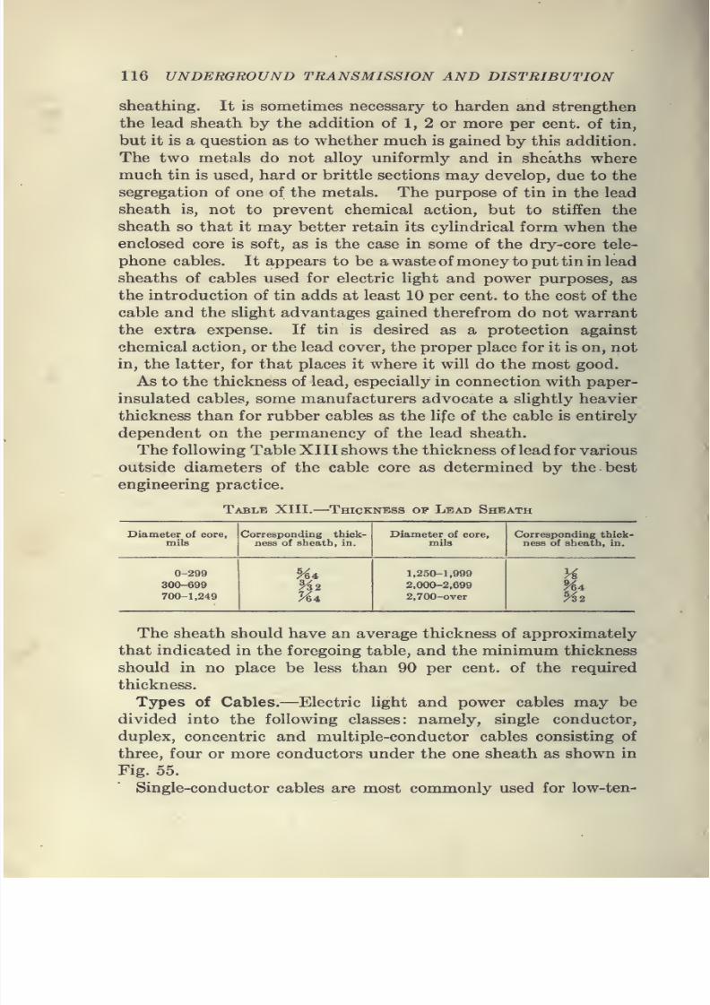
7/28/2019 Underground Trans 00 Me Yeu of t
http://slidepdf.com/reader/full/underground-trans-00-me-yeu-of-t 128/327
116 UNDERGROUND TRANSMISSION AND DISTRIBUTION
sheathing. It is sometimes necessary to harden and strengthen
the lead sheath by the addition of 1, 2 or more per cent, of tin,
but it is a question as to whether much is gained by this addition.
The two metals do not alloy uniformly and in sheaths where
much tin is used, hard or brittle sections may develop, due to the
segregation of one of the metals. The purpose of tin in the lead
sheath is, not to prevent chemical action, but to stiffen the
sheath so that it may better retain its cylindrical form when the
enclosed core is soft, as is the case in some of the dry-core tele-
phone cables. It appears to be a waste of money to put tin inlead
sheaths of cables used for electric light and power purposes, as
the introduction of tin adds at least 10 per cent, to the cost of the
cable and the slight advantages gained therefrom do not warrant
the extra expense. If tin is desired as a protection against
chemical action, or the lead cover, the proper place for it is on, not
in, the latter, for that places it where it will do the most good.
As to the thickness of lead, especially in connection with paper-
insulated cables, some manufacturers advocate a slightly heavier
thickness than for rubber cables as the life of the cable is entirelydependent on the permanency of the lead sheath.
The following Table XIII shows the thickness of lead for various
outside diameters of the cable core as determined by the best
engineering practice.
Table XIII. Thickness op Lead Sheath
Diameter of core,
mils
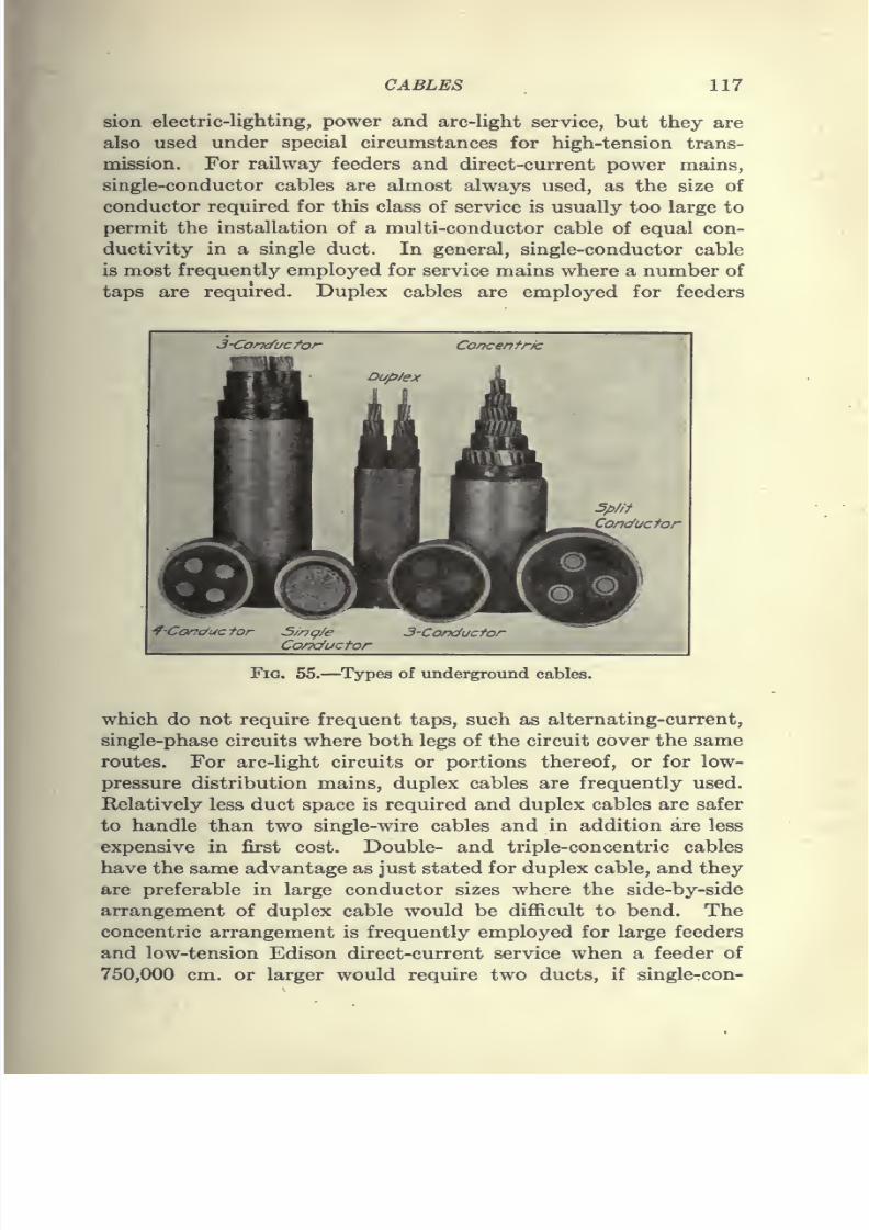
7/28/2019 Underground Trans 00 Me Yeu of t
http://slidepdf.com/reader/full/underground-trans-00-me-yeu-of-t 129/327
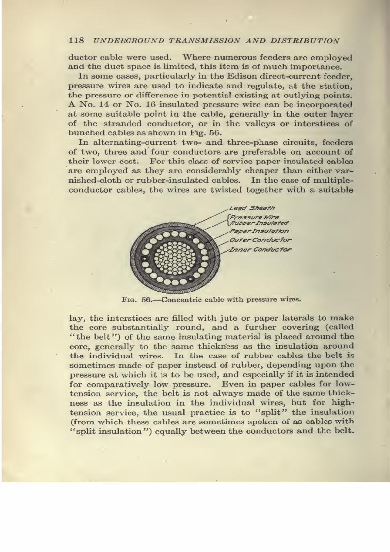
7/28/2019 Underground Trans 00 Me Yeu of t
http://slidepdf.com/reader/full/underground-trans-00-me-yeu-of-t 130/327
118 UNDERGROUND TRANSMISSION AND DISTRIBUTION
ductor cable were used. Where numerous feeders are employed
and the duct space is limited, this item is of much importance.
In some cases, particularly in the Edison direct-current feeder,
pressure wires are used to indicate and regulate, at the station,
the pressure or difference in potential existing at outlying points.
A No. 14 or No. 16 insulated pressure wire can be incorporated
at some suitable point in the cable, generally in the outer layer
of the stranded conductor, or in the valleys or interstices of
bunched cables as shown in Fig. 56.
In alternating-current two- and three-phase circuits, feeders
of two, three and four conductors are preferable on account of
their lower cost. For this class of service paper-insulated cables
are employed as they are considerably cheaper than either var-
nished-cloth or rubber-insulated cables. In the case of multiple-
conductor cables, the wires are twisted together with a suitable
le^ 5/7est/7
Pressure M're
/?ui>i>erl/7au/9te<f
PsperInsu/9tfon
OuterConductor
JnnerConducfor
Fig. 56.—Concentric cable with pressure wires.
lay, the interstices are filled with jute or paper laterals to make
the core substantially round, and a further covering (called
"the belt") of the same insulating material is placed around the
core, generally to the same thickness as the insulation around
the individual wires. In the case of rubber cables the belt is
sometimes made of paper instead of rubber, depending upon the
pressure at which it is to be used, and especially if it is intended
for comparatively low pressure. Even in paper cables for low-
tension service, the belt is not always made of the same thick-
ness as the insulation in the individual wires, but for high-
tension service, the usual practice is to "split" the insulation
(from which these cables are sometimes spoken of as cables with
"split insulation") equally between the conductors and the belt.
7/28/2019 Underground Trans 00 Me Yeu of t
http://slidepdf.com/reader/full/underground-trans-00-me-yeu-of-t 131/327
CABLES 119
When it is desired to connect multiple-conductor cables to
overhead lines, single-conductor cables have been employed, but
with multiple-conductor pole terminals, as described in another
chapter, the use of multiple-conductor cables for the lateral pole
connection is now rapidly becoming general practice.
In single-conductor cables, or an alternating-current system,
carrying heavy loads, there is apt to be an inductive action and
the magnetic field may become strong enough to induce an appre-
ciable difference of potential between the lead sheaths of single-
conductor cables of a circuit, resulting in the flow of sufficient
current to cause damage to the sheaths where they come into
contact with each other. For connections to subway transform-
ers, junction boxes and manhole switches, single-conductor cables
are used to tap on or connect to the multiple-conductor feeders,
as they facilitate the making of such connections.
Diameter and Length of Cables.—As a rule cables having a
diameter of over 33^ in. should not be specified on account of the
difficulty of handling and drawing into the conduits. The greater
the diameter, the greater the danger of the lead cover buckling
or breaking when bent, and abrading in the operation of pulling
in. For underground cables, the net diameter of the duct will
control the maximum diameter of the cable, which latter should
be approximately one-sixth less than the former, and in no case
less than one-eighth smaller in diameter. A margin or difference
of one-fourth the duct diameter represents the best condition for
ease and safety of drawing in cables.
Cable may be made in almost any length, but it is desirable,
on account of manufacturing operations, to confine the length to
certain practical economic limits. Extraordinary lengths re-
quire the temporary adoption of extraordinary methods and de-
vices in manufacture, shipment and installation, at an increased
cost quite out of proportion to the safer and simpler expedient,
practicable in most cases, of making a few more splices or building
a few more manholes. Cables weighing 1 lb. or less per ft. can
usually be supplied in lengths of 2,500 to 3,500 ft. on a single reel,
and heavier cables in approximately inverse proportions; thus
for cables weighing 6 lb. per ft., the reel should contain something
under 600 ft. of cable.
Table XIV gives the maximum length in feet of cable that
can be shipped on standard reels.
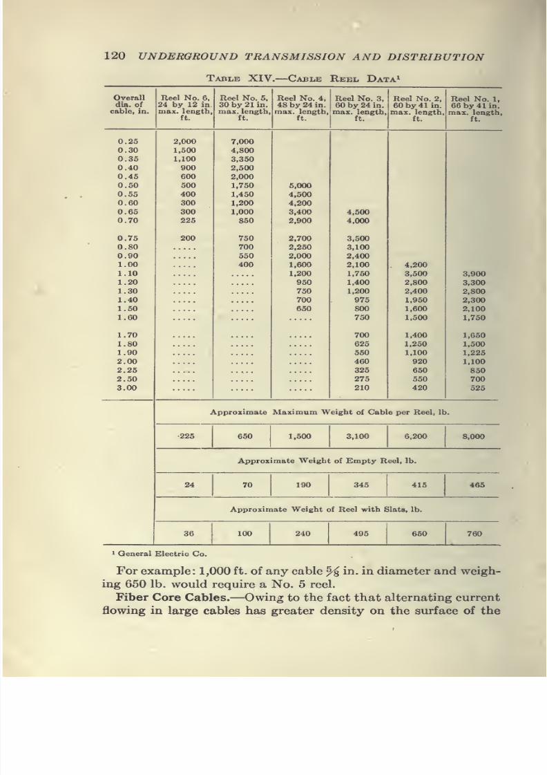
7/28/2019 Underground Trans 00 Me Yeu of t
http://slidepdf.com/reader/full/underground-trans-00-me-yeu-of-t 132/327
120 UNDERGROUND TRANSMISSION AND DISTRIBUTION
Table XIV. Cable Reel Data^
Overall
dia. ofcable, in.
7/28/2019 Underground Trans 00 Me Yeu of t
http://slidepdf.com/reader/full/underground-trans-00-me-yeu-of-t 133/327
CABLES 121
conductor than in the center (so-called skin effect), ordinary
cable will not carry as much alternating current with the same
temperature rise as direct current. In order to overcome this
it is advisable on single-conductor cables, 700,000 cm. and larger
for 60-cycle circuits and 1,250,000 cm. and larger for 25-cycle
circuits, to make up the cable with a fiber core with the copper
stranded around it. The weight of the copper in this type of
cable is the same per foot as in an ordinary cable, but owing to
its annular cross-section the cable is much more efficient in
carrying alternating current and also has a somewhat greater
current-carrying capacity due to the larger radiating surface.
These copper strands can be insulated with any desired type of
insulation.
Table XV gives the diameter of core recommended for various
sizes, and the overall diameter as well as the ampere capacity at
30°C. and 60°C.
Table XV. Fiber Core Cable Data*
Size
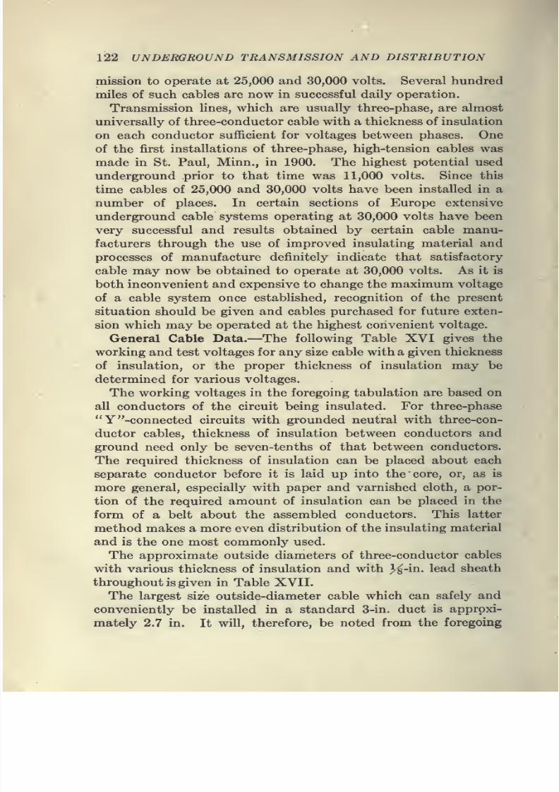
7/28/2019 Underground Trans 00 Me Yeu of t
http://slidepdf.com/reader/full/underground-trans-00-me-yeu-of-t 134/327
122 UNDERGROUND TRANSMISSION AND DISTRIBUTION
mission to operate at 25,000 and 30,000 volts. Several hundred
miles of such cables are now in successful daily operation.
Transmission lines, which are usually three-phase, are almostuniversally of three-conductor cable with a thickness of insulation
on each conductor sufficient for voltages between phases. One
of the first installations of three-phase, high-tension cables was
made in St. Paul, Minn., in 1900. The highest potential used
underground prior to that time was 11,000 volts. Since this
time cables of 25,000 and 30,000 volts have been installed in a
number of places. In certain sections of Europe extensive
underground cable systems operating at 30,000 volts have beenvery successful and results obtained by certain cable manu-
facturers through the use of improved insulating material and
processes of manufacture definitely indicate that satisfactory
cable may now be obtained to operate at 30,000 volts. As it is
both inconvenient and expensive to change the maximum voltage
of a cable system once established, recognition of the present
situation should be given and cables purchased for future exten-
sion which may be operated at the highest convenient voltage.
General Cable Data.—The following Table XVI gives the
working and test voltages for any size cable with a given thickness
of insulation, or the proper thickness of insulation may be
determined for various voltages.
The working voltages in the foregoing tabulation are based on
all conductors of the circuit being insulated. For three-phase
"Y "-connected circuits with grounded neutral with three-con-
ductor cables, thickness of insulation between conductors and
ground need only be seven-tenths of that between conductors.
The required thickness of insulation can be placed about each
separate conductor before it is laid up into the core, or, as is
more general, especially with paper and varnished cloth, a por-
tion of the required amount of insulation can be placed in the
form of a belt about the assembled conductors. This latter
method makes a more even distribution of the insulating material
and is the one most commonly used.
The approximate outside diameters of three-conductor cables
with various thickness of insulation and with 3'^-in. lead sheath
throughout is given in Table XVII.
The largest size outside-diameter cable which can safely and
conveniently be installed in a standard 3-in. duct is approxi-
mately 2.7 in. It will, therefore, be noted from the foregoing
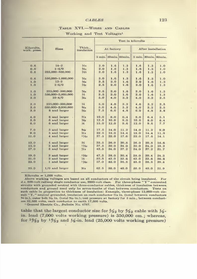
7/28/2019 Underground Trans 00 Me Yeu of t
http://slidepdf.com/reader/full/underground-trans-00-me-yeu-of-t 135/327
CABLES 123
Table XVI. Wires and Cables
Working and Test Voltages^
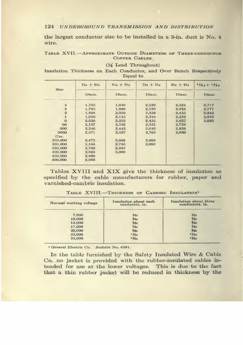
7/28/2019 Underground Trans 00 Me Yeu of t
http://slidepdf.com/reader/full/underground-trans-00-me-yeu-of-t 136/327
124 UNDERGROUND TRANSMISSION AND DISTRIBUTION
the largest conductor size to be installed in a 3-in. duct is No. 4
wire.
Table XVII. Approximate Outside Diameters of Three-conductor
Copper Cables
{}4 Lead Throughout)
Insulation Thickness on Each Conductor, and Over Bunch Respectively
Equal to
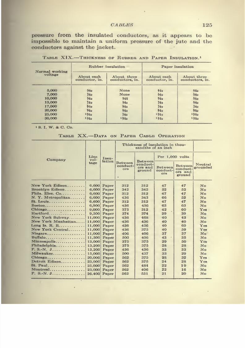
7/28/2019 Underground Trans 00 Me Yeu of t
http://slidepdf.com/reader/full/underground-trans-00-me-yeu-of-t 137/327
CABLES 125
pressure from the insulated conductors, as it appears to be
impossible to maintain a uniform pressure of the jute and the
conductors against the jacket.
Table XIX. Thickness op Rubber and Paper Insulation.^
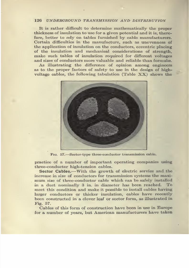
7/28/2019 Underground Trans 00 Me Yeu of t
http://slidepdf.com/reader/full/underground-trans-00-me-yeu-of-t 138/327
126 UNDERGROUND TRANSMISSION AND DISTRIBUTION
It is rather difficult to determine mathematically the proper
thickness of insulation to use for a given potential and it is, there-
fore, better to rely on tables furnished by cable manufacturers.
Certain difficulties in the manufacture, such as unevenness of
the application of insulation on the conductors, eccentric placing
of the insulation and mechanical considerations of strength,
make such tables of insulation required for different voltages
and sizes of conductors more valuable and reliable than formulae.
As illustrating the difference of opinion among engineers
as to the proper factors of safety to use in the design of high-
voltage cables, the following tabulation (Table XX) shows the
Fia. 57.—Sector-type three-conductor transmission cable.
practice of a number of important operating companies using
three-conductor high-tension cables.
Sector Cables.—With the growth of electric service and the
increase in size of conductors for transmission systems the maxi-
mum size of three-conductor cable which can be safely installed
in a duct nominally 3 in. in diameter has been reached. To
meet this condition and make it possible to install cables having
larger conductors or thicker insulation, cables have recently
been constructed in a clover leaf or sector form, as illustrated in
Fig. 57.
Cables of this form of construction have been in use in Europe
for a number of years, but American manufacturers have taken
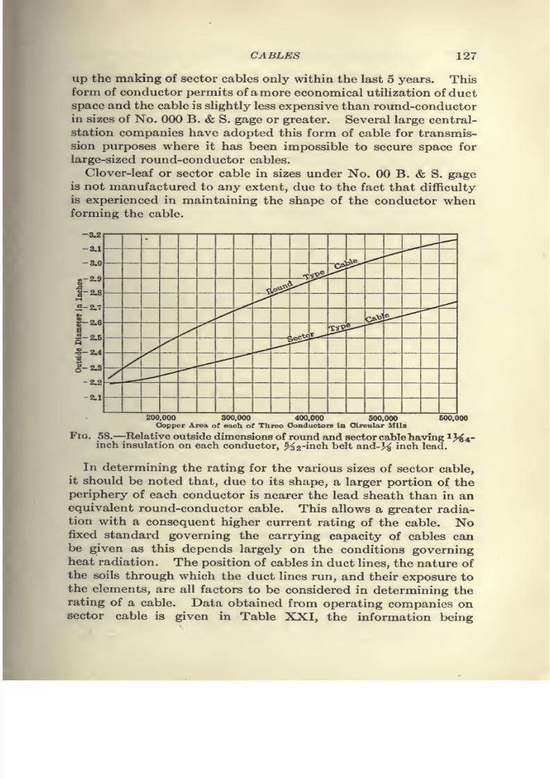
7/28/2019 Underground Trans 00 Me Yeu of t
http://slidepdf.com/reader/full/underground-trans-00-me-yeu-of-t 139/327
CABLES 127
up the making of sector cables only within the last 5 years. This
form of conductor permits of amore economical utihzation of duct
space and the cable is shghtly less expensive than round-conductorin sizes of No. 000 B. & S. gage or greater. Several large central-
station companies have adopted this form of cable for transmis-
sion purposes where it has been impossible to secure space for
large-sized round-conductor cables.
Clover-leaf or sector cable in sizes under No. 00 B. & S. gage
is not manufactured to any extent, due to the fact that difficulty
is experienced in maintaining the shape of the conductor when
forming the cable.
-3.2
-8.1
-8.0
«-2.9o.4
S-2.8M5-2.7b
1-2.6S
1-2.6
1-2.4
1-2.3
-2.2
-2.1
7/28/2019 Underground Trans 00 Me Yeu of t
http://slidepdf.com/reader/full/underground-trans-00-me-yeu-of-t 140/327
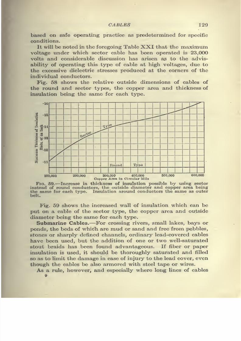
7/28/2019 Underground Trans 00 Me Yeu of t
http://slidepdf.com/reader/full/underground-trans-00-me-yeu-of-t 141/327
CABLES 129
based on safe operating practice as predetermined for specific
conditions.
It will be noted in the foregoing Table XXI that the maximumvoltage under which sector cable has been operated is 23,000
volts and considerable discussion has arisen a^ to the advis-
ability of operating this type of cable at high voltages, due to
the excessive dielectric stresses produced at the corners of the
individual conductors.
Fig. 58 shows the relative outside dimensions of cables of
the round and sector types, the copper area and thickness of
insulation being the same for each type.
-16
7/28/2019 Underground Trans 00 Me Yeu of t
http://slidepdf.com/reader/full/underground-trans-00-me-yeu-of-t 142/327
130 UNDERGROUND TRANSMISSION AND DISTRIBUTION
are to be laid under water, it is best to use rubber-insulated
conductors so that in case the protective covering should be
broken or cut, the insulation will still exclude moisture for a
considerable period of time, if not permanently.
Where the submarine cable is at all likely to be subjected to
considerable tensile strains, the lead sheath should be protected
with a heavy serving of tarred jute, and armored with galvanized-
steel wires of a size varying with the size of the cable and the
conditions under which the cable is to be laid and operated.
Heavily galvanized and pliable medium-strength steel is used
for armor wire and the size and thickness of armor for various
diameters of cable is given in the Standard Armor Table XXII.
When the bottom on which the cables lie is soft and there js
no danger from boats or dragging anchors, paper cables with
extra heavy lead, with or without additional fibrous covering
over the lead, have been used very successfully.
It is impossible to give instructions covering the installation
of submarine cables under all conditions but in general the
following method will be found practicable:
After procuring a tug or boat of suitable size to carry the cable
reel and crew, the reel is mounted on heavy trusses at the bow
of the boat, using a heavy shaft to support the weight and allow
the reel to revolve readily.
The cable should pass from the bottom of the reel over rollers
or pulleys back to the stern of the boat and should be securely
fastened on the shore at its proper location.
Thereel
should be provided with a brake so thatit will
notoverrun as the boat moves, and men should be stationed at the
reel and cable roller to guard against any damage to the cable.
The boat should move slowly to the point where the cable is
to land, and should anchor, or beach, bow on. The remainder
of the cable is then unreeled and dropped alongside, and the shore
end carried to the point at which it is to meet the underground
or aerial line.
The shore end should be laid in a trench extending far enough
into the water to protect the cable against ice and boats which
may ground at such points. In navigable waters a sign, "Cable
Crossing," should be prominently displayed at the cable landings
to prevent damage from boats inadvertently anchoring along
or near the line of the cable.
In the laying of a submarine cable the boat should not be
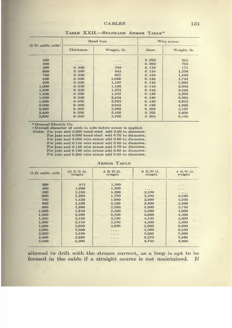
7/28/2019 Underground Trans 00 Me Yeu of t
http://slidepdf.com/reader/full/underground-trans-00-me-yeu-of-t 143/327
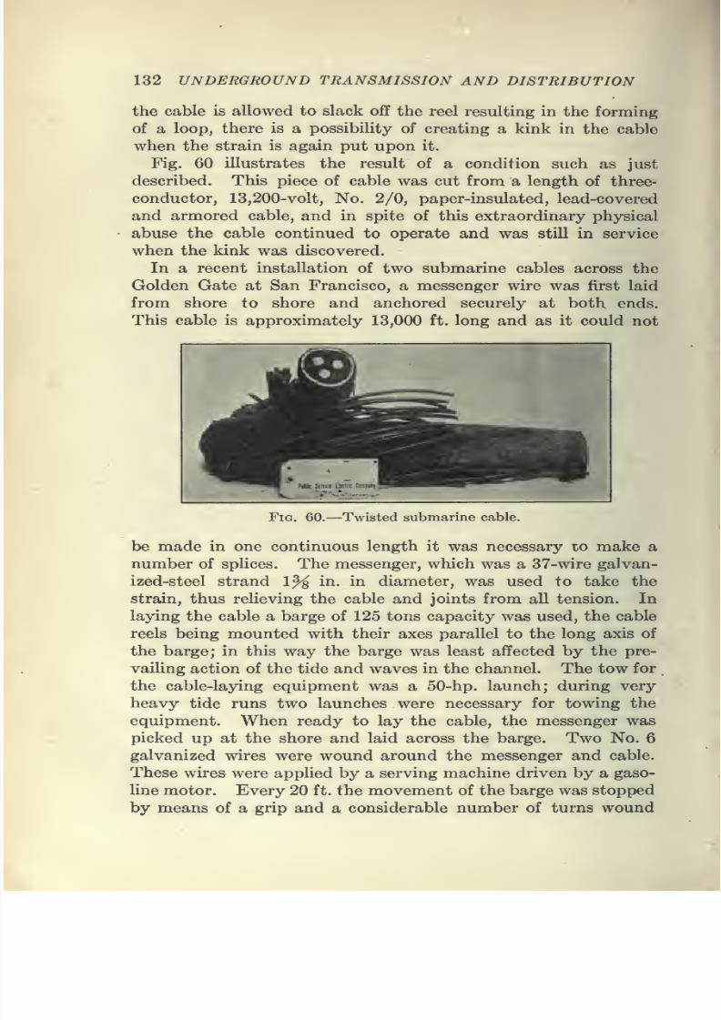
7/28/2019 Underground Trans 00 Me Yeu of t
http://slidepdf.com/reader/full/underground-trans-00-me-yeu-of-t 144/327
132 UNDERGROUND TRANSMISSION AND DISTRIBUTION
the cable is allowed to slack off the reel resulting in the forming
of a loop, there is a possibility of creating a kink in the cable
when the strain is again put upon it.
Fig. 60 illustrates the result of a condition such as just
described. This piece of cable was cut from a length of three-
conductor, 13,200-volt, No. 2/0, paper-insulated, lead-covered
and armored cable, and in spite of this extraordinary physical
abuse the cable continued to operate and was still in service
when the kink was discovered.
In a recent installation of two submarine cables across the
Golden Gate at San Francisco, a messenger wire was first laid
from shore to shore and anchored securely at both ends.
This cable is approximately 13,000 ft. long and as it could not
Fig. 60.—Twisted submarine cable.
be made in one continuous length it was necessary lo make a
number of splices. The messenger, which was a 37-wire galvan-ized-steel strand 1% in. in diameter, was used to take the
strain, thus relieving the cable and joints from all tension. In
laying the cable a barge of 125 tons capacity was used, the cable
reels being mounted with their axes parallel to the long axis of
the barge; in this way the barge was least affected by the pre-
vailing action of the tide and waves in the channel. The tow for
the cable-laying equipment was a 50-hp. launch; during very
heavy tide runs two launches were necessary for towing the
equipment. When ready to lay the cable, the messenger was
picked up at the shore and laid across the barge. Two No. 6
galvanized wires were wound around the messenger and cable.
These wires were applied by a serving machine driven by a gaso-
line motor. Every 20 ft. the movement of the barge was stopped
by means of a grip and a considerable number of turns wound
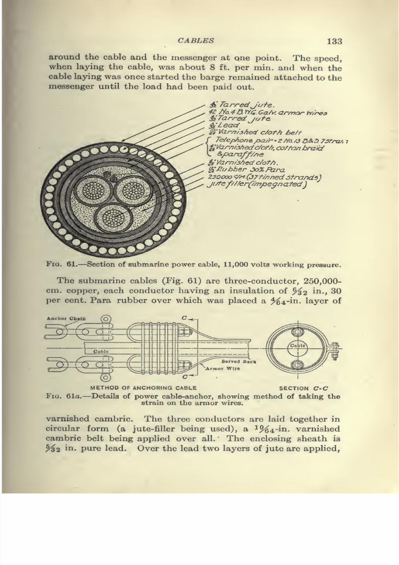
7/28/2019 Underground Trans 00 Me Yeu of t
http://slidepdf.com/reader/full/underground-trans-00-me-yeu-of-t 145/327
7/28/2019 Underground Trans 00 Me Yeu of t
http://slidepdf.com/reader/full/underground-trans-00-me-yeu-of-t 146/327
134 UNDERGROUND TRANSMISSION AND DISTRIBUTION
to a total thickness of ^^2 ^^- The jute forms a cushion for the
steel-wire armor, consisting of 42 wires of No. 4 B.W.G. extra
heavy galvanized iron and this armor is in turn covered with
a layer of jute %2 int. thick, to which was applied a sand and
asphaltum finish for mechanical protection.
Each cable contains a twisted pair of telephone wires of No.
13 B. & S. copper. Fig. 61a shows the detail of the power-cable
anchor and method of taking the strain on the armor wires.
Specifications.—In submitting specifications to cable manu-
facturers, it is well to state the conditions under which the cable
will be used as this will assist the manufacturer in determining
the particular cable which will best suit the operating conditions.
When the specific requirements covering details of construction,
tests and guarantees of cable are furnished, a more perfect under-
standing is established and the manufacturer can better serve the
customer's needs. Specifications are of all classes, good, bad and
indifferent, and taken collectively, indicate a wide difference in
ideas. On the cable depends the success of the electrical system
of transmission and distribution as a poorly constructed or
improperly insulated wire or cable will surely imperil the service.
The insulation should be of the proper kind and quality for the
purpose intended. To insure the service the cable must be
properly tested, properly installed and properly protected.
Cable should be tested at the manufacturer's plant before
shipment, at a potential somewhat higher than the maximum
working voltage and it is essential that a similar test be made
after installation. There still seems to be a difference of opinionas to the proper pressure and duration of such tests and there is
a great tendency on the part of engineers to make this test too
severe. In general it may be said that tests of two and one-half
times working pressure for 30 min. at the factory and twice
the working pressure after installation for 15 min. are considered
conservative. Cables tested under these conditions have given
no indication in practice that the margin of safety was not ample.
High-potential tests are not intended to show the ultimate strengthof the cable, but to show that the cable is safe and satisfactory
for the purpose for which it is intended.
In many cases engineers have specified high-puncture tests on
cables and it was considered that if the insulation passed these
exacting tests it was in first-class condition. High-potential
tests frequently strain the insulation to such an extent that the
7/28/2019 Underground Trans 00 Me Yeu of t
http://slidepdf.com/reader/full/underground-trans-00-me-yeu-of-t 147/327
CABLES 135
cable fails after the first physical or potential strain is imposed
upon it. A high-potential test is not always conclusive proof of
insulatingmerit,
but on the other hand it should not be assumedthat puncture tests areof no value. The object of puncture tests
is to disclose imperfections in the insulating wall of the cable and
in this respect they are of great importance. A cable may be
well made of poor material or it may be imperfectly made of the
very best material. In the one case there is good workmanship
with poor material, and in the other, bad workmanship with
good material.
Cable specifications in general should provide for the fixing
of the copper conditions, the insulating material, the sheath or
braid and the mechanical, electrical and chemical tests. They
should include clauses providing for the methods of tests and
apparatus to be used and, finally, instructions as to the method
of packing and shipping. It should not be the intent of the
specification to tell the manufacturer how he shall make the cable.
The main purpose should be to state the operating conditions
which the cable must satisfy in order that the manufacturer may
endeavor to meet these conditions.
Details of installation and service may radically affect the
design of any cable and it is, therefore, necessary that full infor-
mation be given the manufacturer in order to secure intelligent
consideration and to insure correct design.
Rubber-insulated Cable Specifications.—The numerous speci-
fications for 30 per cent, rubber compound do not materially
differ as to chemical tests, nor in their requirements for mechani-
cal properties as determined by stretch, return, and ultimate
break. Many requirements for chemical and mechanical prop-
erties now found in specifications for 30 per cent, compounds
appeared originally in specifications for wires and cables intended
for low-tension service. The same requirements were later
incorporated in specifications for high-tension service and ac-
cepted as satisfactory, but experience has developed the fact that a
change should have been made to secure the best results for this
work. The ingredients of a compound govern its characteristics,
and a change in the proportion of a given ingredient may improve
one characteristic to the detriment of another. Many engineers
leave the thickness of the insulation to be determined by the
manufacturer from specified tests. This practice has the dis-
advantage of permitting the various competing manufacturers
7/28/2019 Underground Trans 00 Me Yeu of t
http://slidepdf.com/reader/full/underground-trans-00-me-yeu-of-t 148/327
136 UNDERGROUND TRANSMISSION AND DISTRIBUTION
to submit their bids based on different thicknesses of insulation
and safety factors.
There are many different grades of rubber, all varying in
price as in quality, and it is only by a knowledge and recognition
of this wide diversity of character that an engineer can intelli-
gently make up specifications and rigidly enforce them. The
better grades of rubber insulation contain from 20 to 40 per cent.
Para rubber.
The specific gravity of rubber compounds varies from 1.10
to 2.0 depending on the ingredients used. The higher the per
cent, of rubber, the lower the specific gravity. The tensile
strength of high-grade rubber compound is about 1,200 lb. per
sq. in.
Rubber insulation, owing to its composition, attacks copper and
it is, therefore, necessary that the conductor be properly tinned
before the insulation is applied. In testing rubber-covered
cables it is customary to apply the potential test at the factory
while the cables are immersed in testing tanks in which the water
is
maintained at a constant temperature. These tests are madewhen the conductor is covered with the vulcanized compound
and before the application of any covering other than a non-
waterproof tape. The analysis of rubber compounds presents
extraordinary difficulties and in the present state of the art no
one procedure is applicable to all compounds. Serious difficul-
ties have arisen in the past, due to the want of standard methods.
For several years no attempt was made to standardize specifica-
tions, and much trouble was given the manufacturers by the di-
versity of requirements contained in the various specifications.
In 1911, Mr. E. B. Katte, chief engineer of electric traction
of the New York Central and Hudson River Railroad Co.,
invited a number of manufacturers and consumers to a confer-
ence in order to discuss the possibility of standardizing specifica-
tions and analytical methods for rubber insulation. As a result
of this conference which was held in New York on Dec. 7, 1911, a
committee was appointed to devise a specification and analytical
procedure for rubber insulation. The committee, which has
become known as the Joint Rubber Insulation Committee, was
composed of men representing the various interests, and a report
was submitted on the procedure for chemical analysis and the
interpretation of the results obtained. A specification and chem-
ical limits for a 30 per cent, compound was also included.
7/28/2019 Underground Trans 00 Me Yeu of t
http://slidepdf.com/reader/full/underground-trans-00-me-yeu-of-t 149/327
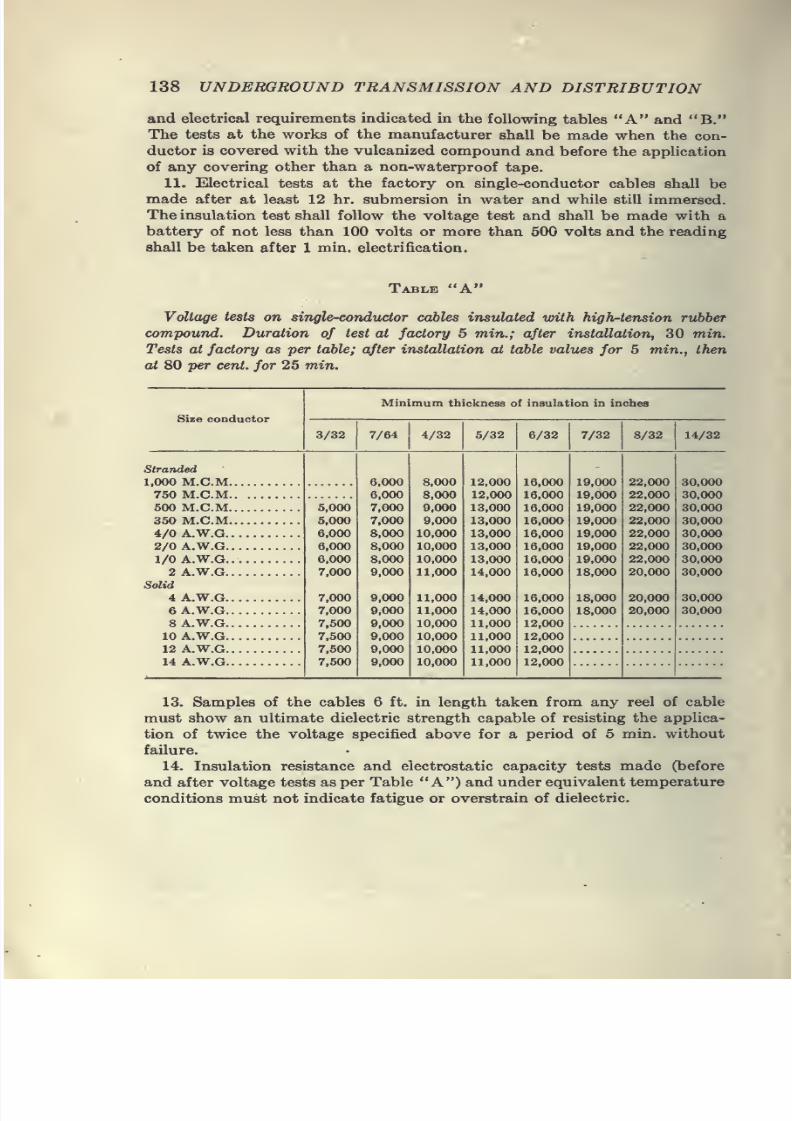
7/28/2019 Underground Trans 00 Me Yeu of t
http://slidepdf.com/reader/full/underground-trans-00-me-yeu-of-t 150/327
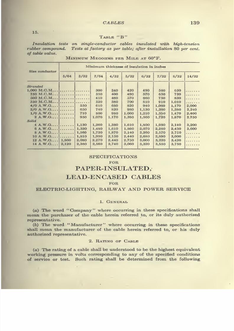
7/28/2019 Underground Trans 00 Me Yeu of t
http://slidepdf.com/reader/full/underground-trans-00-me-yeu-of-t 151/327
CABLES 139
15.
Table "B"
Insulation tests on single-conductor cables insulated with high-tension
rubber compound. Tests at factory as per table; after installation 80 per cent,
of table valu£.
Minimum Megohms per Mile at 60°F.
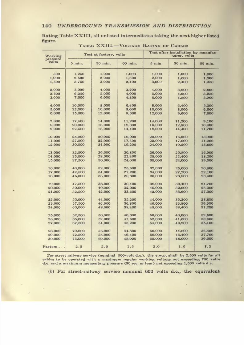
7/28/2019 Underground Trans 00 Me Yeu of t
http://slidepdf.com/reader/full/underground-trans-00-me-yeu-of-t 152/327
140 UNDERGROUND TRANSMISSION AND DISTRIBUTION
Rating Table XXIII, all unlisted intermediates taking the next higher listed
figure.
Table XXIII. Voltagk Rating op Cables
Working
7/28/2019 Underground Trans 00 Me Yeu of t
http://slidepdf.com/reader/full/underground-trans-00-me-yeu-of-t 153/327
CABLES 141
working pressure shall be 2,500 volts for all cables to be operated with a
maximum regular working voltage not exceeding 750 volts d.c, and a
maximum momentary pressure (30 sec. or less) not exceeding 1,500 volts d.c.
(c) For three-conductor three-phase "Y "-connected circuits with
grounded neutral, the thickness of insulation between any conductor and
ground need be only seven-tenths of that between conductors, and the test
voltage between any conductor and ground may be taken at seven-tenths
of the above tabulated figures for the corresponding equivalent working
pressure.
3. CJONDUCTORS
(a) Each conductor shall consist of not less than the following number
of soft-drawn copper wires free from splints, flaws, joints, or defects of anykind, and having at least 98 per cent, conductivity of that of pure annealed
copper, as defined by the American Institute of Electrical Engineers
Standardization Rules. The conductors shall be concentrically stranded
together having an aggregate cross-sectional area when measured at right
angles to the axes of the individual wires at least equal to that corresponding
to the specified size, viz:
No. 4 B. «& S. G and smaller Solid
No. 3 B. & S. G to No. 2 B. & S. G. . . 7-wire strand
No. 1 B. & S. G to No. 4/0 B. & S. G..
19-wire strand
250,000 cm to 500,000 cm 37-wire strand
600,000 cm to 1,000,000 cm. . . . ; . . 61-wire strand
1,100,000 cm to 2,000,000 cm 97-wire strand
2,100,000 cm and larger 127-wire strand
Intermediate sizes take the stranding of the next larger listed size.
4. Insulation
(a) The insulation shall consist of the best manila paper free from jute,
wood fiber or other foreign material applied helically and evenly on the con-
ductor, and shall be capable of withstanding the test and service conditions
corresponding to the highest equivalent working pressure as determined from
the rating table set forth in paragraph 2 hereof. In the case of the cables
consisting of more than one conductor (except concentric cables) and Fig.
8 or flat form of duplex cables, the separately insulated conductors shall be
twisted together with a suitable lay, and interstices rounded out with the
jute before the belt insulation is applied. The minimum insulation thick-
ness or thicknesses shall in no case be less than 90 per cent, of the agreed
average thickness or thicknesses. The completed core shall be thoroughlyinsulated with an insulating compound.
5. Sheath
(o) The sheath shall have an average thickness of not less than that
indicated in the tabulation next following and the minimum thickness
shall in no case be less than 90 per cent, of the required average thickness.
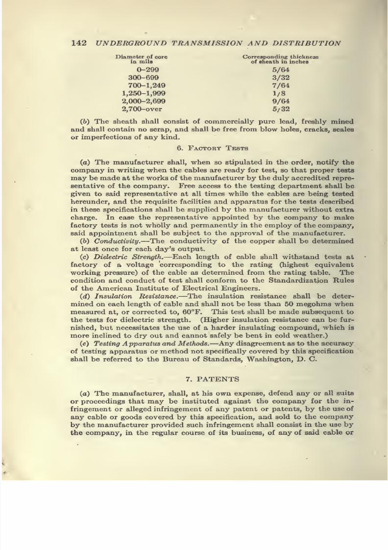
7/28/2019 Underground Trans 00 Me Yeu of t
http://slidepdf.com/reader/full/underground-trans-00-me-yeu-of-t 154/327
7/28/2019 Underground Trans 00 Me Yeu of t
http://slidepdf.com/reader/full/underground-trans-00-me-yeu-of-t 155/327
CABLES 143
goods or parts thereof, and provided the company gives to the manufacturer
immediate notice in writing, of the institution of the suit, or proceedings,
and permits the manufacturer through his counsel, to defend the same and
gives all needed information, assistance, and authority to enable the manu-facturer so to do, and thereupon, in case of an award of the damages, the
manufacturer shall pay such award and in case of an injunction against the
company, the manufacturer shall, upon return of the article, the use of
which has been enjoined, repay to the company the amount paid by it for
the same.
8. QUANTITIES
(o) The quantity of each cable specified in the order shall be subject
to an increase or decrease of not exceeding 5 per cent., at the option of the
company, provided that such option is exercised by the company in writing
not less than 30 days before the date fixed for final shipment on account of
said order.
9. SHIPMENTS
(o) Unless otherwise provided all deliveries shall be f.o.b. factory of the
manufacturer. Any material not called for by the company in time to
permit the manufacturer (at the agreed shipping rates) to make shipment
within the agreed time, and for which final shipping instructions are not
filed by the company with the manufacturer at least 1 month prior to the
expiration of said agreed time, shall be paid for as if shipped at the expiration
of said agreed time. Provided, however, that said agreed time shall not be
more than 6 months after date of order. A receipt given by the company
or its representatives for any material shipped by the manufacturer, and
which fails to note any apparent injury to or bad condition of reels, cases or
contents shall terminate the manufacturer's responsibility for the condition
of said material.
10. REELS
(o) All reels and lagging shall not be included in the contract price, but
shall be charged separately therefrom and shall be paid for in accordance
with paragraph 11 thereof, "Terms of Payment," and when returned f.o.b
shipping factory in good condition complete with all lagging (reasonable
wear and tear excepted) within 6 months from date of shipment shall be
credited at the price charged. Reels and lagging thus returned after 6
months from date of shipment shall be credited at one-half the price originally
charged.
(6) Each reel shall be plainly marked, giving the length of cable, pur-
chaser's order number, and date of manufacture. Each reel shall have anumbered metal tag, permanently attached.
11. TERMS OF PAYMENT
(o) Net cash within 30 days from date of payment by manufacturer; or
}i per cent, discount for cash within 10 days from said date of shipment.

7/28/2019 Underground Trans 00 Me Yeu of t
http://slidepdf.com/reader/full/underground-trans-00-me-yeu-of-t 156/327
144 UNDERGROUND TRANSMISSION AND DISTRIBUTION
12. INSTALLATION BY MANUFACTURER
(a) The following additional conditions contained in paragraphs 12 to
22, both inclusive, hereof shall apply when cable is installed in underground
ducts and manholes by the manufacturer, and then only; in which case the
conditions of paragraphs 10 and 11 hereof shall be cancelled.
13. PERMITS AND INFORMATION
(a) The company shall provide all necessary permits and information
to enable the manufacturer to carry on the work uninterruptedly.
14. MEASUREMENTS
(a) The company shall furnish the manufacturer correct measurements
for detail manufacturing lengths, but in case the company so elects at the
time of placing the order, the manufacturer shall make said measurements,
which shall be approved by the company before the manufacture of the
cable is begun. In either case the lengths as thus determined shall be paid
for under paragraph 21 hereof, relating to "payments," and the scrap or
excess cable, if any, shall become the property of the company.
15. CONDUITS, MANHOLES, ETC.
(a) All conduits, manholes, or locations provided by the company for
the reception of cable shall be clean and free from obstructions, safe and
suitable for the purpose intended. The ducts shall be such as to permit, the
passing through them of a steel mandrel, 3 ft. in length and of a diameter at
least % in. greater than that of the cable to be installed therein, but in no
case of a smaller diameter than 3^ in. less than that of the nominal diameter
of the ducts; in case obstructions or defects in the ducts assigned by the
company cause unavoidable delay to the manufacturer or damage to cable
through attempts to install therein, the company shall pay to the manu-
facturer the actual loss resulting from said delay, and cost of repairing said
damage.
16. JOINTING
(a) The manufacturer shall make all joints in a substantial and work-
manlike manner, using proper connectors of the proper conductivity, which
shall be sweated to the conductor so as to furnish perfect continuity at all
points. Sufficient insulating material shall be supplied to insure insulationand dielectric strength equal to the average obtained to equal lengths of the
cable as manufactured. The joints shall be provided with lead sleeves of
thickness not less than that of the sheath of the cable; they shall be thor-
oughly made, wiped, and filled with compound to prevent the probability
of moisture, reaching the insulation.
7/28/2019 Underground Trans 00 Me Yeu of t
http://slidepdf.com/reader/full/underground-trans-00-me-yeu-of-t 157/327
CABLES 145
17. INSTALLED TEST
(o) After the cable is pulled in and jointed by the manufacturer, and
before being put into service, it shall be subjected to an installed test at a
voltage corresponding to the rating or highest equivalent working pressure
of the cable as determined from the rating table set forth in paragraph 2
hereof. Unless otherwise specified by the company in writing at or prior
to time of test, the latter shall be the listed test for 5 min. set forth in said
rating table. The necessary current and apparatus for making the test
shall be supplied by the company, the conditions and conduct of tests shall
conform to the recommendation of the Standardization Rules of the Ameri-
can Institute of Electrical Engineers.
18. TERMINALS AND JUNCTION BOXES
(a) Terminals, junction boxes, manhole cable supports and in general
all cable accessories or auxiliary apparatus not necessarily required to be
used in connection with the pulling in and jointing of the cable, shall be
provided by the company.
(6) If so instructed by the company, the manufacturer shall make con-
nection between the cable and terminals, junction boxes, or equivalent, but
shall not be required to guarantee the same hereunder unless said terminals
and junction boxes or equivalent are approved by him.
(c) In any estimate or count of the number of joints the following under-
standing shall apply: ,
Each straight joint counts as one joint.
Each additional branch or tap cable from a straight joint counts as one
joint.
Each cable entering or leaving a junction box, test box, terminal, pothead
or equivalent, counts a'' one joint.
19. GUARANTEE
(a) In case any cable furnished hereunder fails within 1 year from date of
shipment by the manufacturer, and said failure results from defects of
material or workmanship for which the manufacturer is shown to be solely
responsible, the manufacturer shall be immediately notified and shall
(being given sufficient time to enable him to do so) at his own expense make
all necessary repairs to make the cable affected, in every way equal to its
condition previous to its failure.
(6) Should the manufacturer fail to attend to the repairs promptly, or
should the exigencies of the company's business be such as to necessitate
repairs before the manufacturer can be notified, the company shall have the
right to make the necessary repairs at the manufacturer's expense, preserving
the available evidence of the cause of the failure.
(c) Should the evidence fail to show the liability of the manufacturer
under this specification, the company shall pay to the manufacturer the
cost of repairs made by the latter.
10
7/28/2019 Underground Trans 00 Me Yeu of t
http://slidepdf.com/reader/full/underground-trans-00-me-yeu-of-t 158/327
7/28/2019 Underground Trans 00 Me Yeu of t
http://slidepdf.com/reader/full/underground-trans-00-me-yeu-of-t 159/327
CABLES 147
bending test is included. In European cables the bending test
is applied three times to a radius of six times the cable diameter.
American manufacturers consider as too severe a bending test,
first in one direction and then in the other, twice repeated, to a
radius of six times the cable diameter. The specification here-
with presented, therefore, increases the radius of bending to seven
and one-half times the cable diameter.
Insulating Material
The insulating material shall be of the best manila paper,
free from jute, wood fiber, or other foreign material. It shall becut in strips and helically and evenly applied to the conductor
to a uniform thickness of /32 in. After insulation the three
conductors shall be laid together, with a uniform twist, having
a pitch not exceeding 25 times the diameter of one conductor
measured over the insulation. The interstices shall be filled with
jute or paper so as to form a true firm cylinder without openings
or air spaces, over which is to be applied a paper-insulating
jacket in the same manner, and of the same quality as specifiedfor each conductor.
During the process of applying the paper insulation and the
jute or paper filler and immediately before the insulation is
impregnated, the cable shall be subjected to such treatment as
will insure the expulsion of all air and moisture, incident to
which treatment the cable shall be impregnated with an insulat-
ing compound of low specific inductive capacity, guaranteed not
torun
appreciablyand to
retain its stickyadhesive
qualities
during the life of the cable, and also guaranteed not to develop
any chemical action within itself or with any other component of
the completed cable.
Tests
The following electrical tests shall be made by the manufacturer
at his works and without expense to the purchaser, the manu-
facturer supplying all necessary apparatus and the purchaser
to have the privilege of being represented when these tests are
conducted. The manufacturer shall furnish the purchaser with
copies of data sheets showing the behavior of the cable during
these tests.
(o) Voltage Test.—Each length of cable is to be tested with alternating
current, having a frequency preferably the same as that of the system of
7/28/2019 Underground Trans 00 Me Yeu of t
http://slidepdf.com/reader/full/underground-trans-00-me-yeu-of-t 160/327
148 UNDERGROUND TRANSMISSION AND DISTRIBUTION
which the cable is to be a part. The test voltage is to be applied between
all three conductors and between conductors and lead sheath at a tem-
peratureof
150°F.If the
cableis to
form part of a system having a per-manently grounded neutral, the neutral point of the test generator shall be
connected to the cable sheath during the test. If the cable is to form part
of a system with an ungrounded neutral, two tests shall be made, the first
with conductor A, the second with conductor B, grounded to the cable
sheath. The apparatus supplying the energy for the voltage test must
have a kilovolt-ampere capacity at least four times the kilovolt-ampere
capacity absorbed by the length under test, and in any event must not be
less than 25 kva. capacity. The time of application of the test and test
pressure shall be: 5 min. at a voltage having a peak value two and one-
half times the peak value of the normal working pressure as determined byspark-gap in accordance with the American Institute of Electrical Engineers
Standardization Rules.
(6) Insulation Resistance Test.—(1) An insulation-resistance test shall be
made immediately before and after the voltage test. (2) The measurement
shall be made with a direct-current voltage of not less than 100 volts, the
reading to be taken after 1 min. electrification, and shall show no appreciable
decrease in the value of the insulation resistance between the two. successive
measurements. Measurements shall be made between each conductor
and each of the other two and between each conductor and the lead sheath.
Any section of cable which shows a marked variation from others of the
same type manufactured at the same time shall be held for further examina-
tion and if such variations cannot be satisfactorily explained the section shall
be rejected.
(c) Breakdown Test.—Samples from 10 to 25 ft. long and selected by the
purchaser at random from any cable lengths shall not break down under
five times the working pressure applied for 5 min. between all three con-
ductors and between conductors and lead sheath, after samples with ends
sealed have remained at a temperature of 150°F. for 100 hr. in straight single
lengths with axes inclined 15° to the horizontal.
(d) Bending Test.—A sample from any length of cable shall be bent around
a cylinder having a diameter equal to 15 times the outside diameter of the
cable over lead sheath, and then be straightened out. It shall then be bent
in the opposite direction around the cylinder and straightened out. This
operation shall be performed twice in succession, after which the cable
shall be capable of withstanding a voltage test two and a half times working
pressure applied for a period of 5 min. between the conductors and between
the conductors and the lead sheath, and shall show no signs of mechanical
injury or electrical injury when dissected.
Test after Installation.—The cable shall be capable of withstanding twice
normal working pressure applied between all three conductors and between
conductors and lead sheath for a period of 10 min., after being drawn into the
ducts and jointed. An insulation-resistance test shall be made immediately
before and after the breakdown test, vising the method specified under (6-2)
above, and the insulation resistance shall not be materially reduced as a
result of this test.
7/28/2019 Underground Trans 00 Me Yeu of t
http://slidepdf.com/reader/full/underground-trans-00-me-yeu-of-t 161/327
CABLES 149
Moisture in Cable Insulation.—Some companies, in their
high-tension paper-insulated cable specifications, include a clause
to limit the percentage of moisture in the insulating compound.This appears to be a step in the right direction but such specifica-
tions should be accompanied by an exact description of the
method to be employed in determining the percentage of water
in the insulating compound.
Different methods of tests give different results, some of which
are accurate only to within approximately 25 per cent. It is
evident that in order to have accurate results the insulation
must be removed from the lead and copper and the difficulty is
to accomplish this without exposing the insulation to the air,
thus allowing it to absorb moisture, so that tests made from the
same cable show variations in accordance with the percentage
of moisture in the atmosphere at the time the tests are made.
In the production of high-grade transformer oils, great care
is used to eliminate even minute percentages of moisture. In
ordinary cases J-fo per cent, is considered objectionable, and it
is believed that where trouble is experienced with impregnated-
paper cables it is due to the lack of this same attention to the
question of moisture in the original compound or in the paper
itself.
The rosin of commerce which is used for a base in most paper
cables is the residue from a steam-distillation process for turpen-
tine and contains from 8 to 10 per cent, of water. The rosins
obtained from the so-called "dry process" contain less moisture
than this, but are of an inferior grade.
In usual methods of making rosin-oil compound the mixture
of rosin and oil is heated so that the water is boiled off. This
method, if carried to an extreme, may result in the reduction
of the water to as low as 1 per cent., but in common practice rarely
reaches this minimum. There is also water present in unstable
molecular combination with the rosin and when cable is operated
above normal temperatures this molecular condition is destroyed,
and actual water and a further liberation of volatile ingredients
results. This fact apparently accounts for some cable troubles
which are otherwise unexplainable.
However, the present-day methods of paper-cable manufacture
have reached a degree of perfection where very little trouble
need be feared from overheating due to the presence of residual
moisture in the insulation, if the cable is operated within the
7/28/2019 Underground Trans 00 Me Yeu of t
http://slidepdf.com/reader/full/underground-trans-00-me-yeu-of-t 162/327
150 UNDERGROUND TRANSMISSION AND DISTRIBUTION
limits of voltage for which it has been designed. Only in cases
where the insulation has not been properly treated will excessive
dielectric losses be noticed.
Numerous tests have been made to determine heating due to
dielectric losses, but in no case have these losses been found to
be abnormal provided the cable insulation has been properly
treated and applied.
It would, therefore, seem that there is no good reason for
believing that there is ever enough residual moisture in the cable
insulation to cause any appreciable increase in normal dielectric
hysteresis, and that where companies are experiencing trouble
of this nature the cause is not due to residual moisture in the
compound, but to moisture entering the cable after installation,
either through small holes in the lead sheath, or when joints are
made under unfavorable conditions in damp weather.
7/28/2019 Underground Trans 00 Me Yeu of t
http://slidepdf.com/reader/full/underground-trans-00-me-yeu-of-t 163/327
CHAPTER VI
INSTALLATION OF CABLES
Handling Lead Cables.—No attempt will be made to indicate
all the details of cable installation; it is the intention rather to
outline the general method of installing underground cables and
to emphasize the importance of some parts of the work in con-
nection therewith. Cables are shipped from the manufacturers
on wooden reels of suitable size to accommodate one or more
lengths of cable.
When coiling a cable on a reel, the first end, usually termed the
test end, is put through a slanting smooth hole in the side of the
reel so as to have both ends of the cable accessible for testing
before shipment. After testing, both ends are capped or sealed,
thus protecting the cable insulation from moisture. The test
end of the cable is usually left protruding through the side of
the reel from 12 to 18 in. and is boxed over. It is customary to
lag the reel from flange to flange with heavy wooden slats nailed
to the flanges and further secured by wires encircHng the slats
to protect the cable thoroughly from injury in transit or while
standing on the street.
Transporting reels of cable from the railroad to the manhole
should be entrusted only to experienced truckmen; and if a lowwagon is not available, and a high wagon must be used, the reels
of cable should be carefully lowered from the wagon by means of
a windlass and skids and not allowed to drop to the ground. To
avoid the loosening of the cable, the reels should be rolled in the
direction of the point of the arrow painted on the side of the reel.
The reel of cable is then placed at the manhole, over the duct
into which the cable is to be drawn, in such a way that the cable
will unwind from the top of the reel. It should next be mountedon jacks and not until that is done should the slats be removed,
care being taken that no nails come into contact with the cable
or are left in the flanges to do damage.
An improved form of jack designed to handle cable reels of
varying sizes is shown in Fig. 62. It is provided with three
161
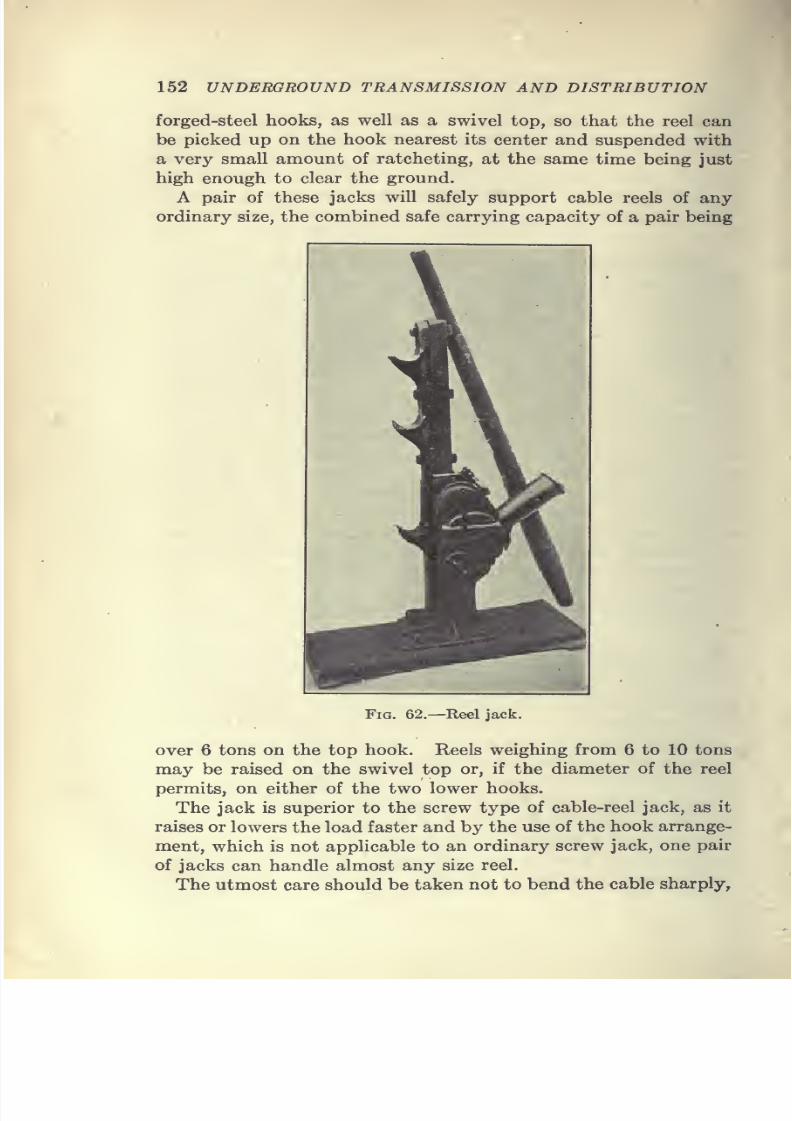
7/28/2019 Underground Trans 00 Me Yeu of t
http://slidepdf.com/reader/full/underground-trans-00-me-yeu-of-t 164/327
152 UNDERGROUND TRANSMISSION AND DISTRIBUTION
forged-steel hooks, as well as a swivel top, so that the reel can
be picked up on the hook nearest its center and suspended with
a very small amount of ratcheting, at the same time being just
high enough to clear the ground.
A pair of these jacks will safely support cable reels of any
ordinary size, the combined safe carrying capacity of a pair being
Fig. 62.—Reel jack.
over 6 tons on the top hook. Reels weighing from 6 to 10 tons
may be raised on the swivel top or, if the diameter of the reel
permits, on either of the two lower hooks.
The jack is superior to the screw type of cable-reel jack, as it
raises or lowers the load faster and by the use of the hook arrange-
ment, which is not applicable to an ordinary screw jack, one pair
of jacks can handle almost any size reel.
The utmost care should be taken not to bend the cable sharply,
7/28/2019 Underground Trans 00 Me Yeu of t
http://slidepdf.com/reader/full/underground-trans-00-me-yeu-of-t 165/327
I
INSTALLATION OF CABLES 153
nor to break through, cut, abrade, kink or dent the lead sheath;
and, above all, not to allow the sHghtest trace of moisture to
enter the ends of the cable after the seals have been broken. Afailure to observe these points may result in the loss of the cable.
The useful life of an underground cable is determined by that of
the insulation, which in turn usually depends upon the integrity
of the lead sheath.
Choice of Ducts.—Before drawing cables into a new conduit
system, there is often a question as to which of the ducts shall be
used first. Workmen, when about to install cables, may have
been told to use any one of the ducts, and naturally they draw
the cable into those which are most convenient, without any
consideration for the cables which are to be installed later.
There are cases where a manhole has been completely blocked
by the first few cables installed. There is another important
reason for using care in the selection of the ducts to be used for
power cables, as will be seen from the following:
It is not possible to foretell the current-carrying capacity of
a cable without previous knowledge of all the controlling factors
which will influence temperature rise in such a cable. Some
of the most important factors are: natural temperature of the
ducts and manholes; amount of moisture present; condition and
action of soil surrounding the conduit; and exact location of the
cable in the conduit with respect to other cables which have
previously been installed. All of these greatly influence both the
radiation and dissipation of heat generated in each conductor or
cable and consequently the current-carrying capacity of the
conductor.
Usually the ducts which dissipate heat most rapidly, and there-
fore run coolest, are those located at the lower corners of the
conduit. Those nearest to the outside of the system run fairly
cool, but the middle and top ducts, which not only take up heat
from the lower cables but must dissipate heat through adjoining
ducts, operate at a fairly high temperature. Attention to these
points, when planning a new system, may prove very profitable
in the end.
Regarding the selection of cables, it should be borne in mind
that other conditions being equal, those insulated with rubber
compound dissipate heat more readily than those insulated with
paper or other fibrous material. On the other hand, it has been
found that a cable insulated with an oil-saturated paper will
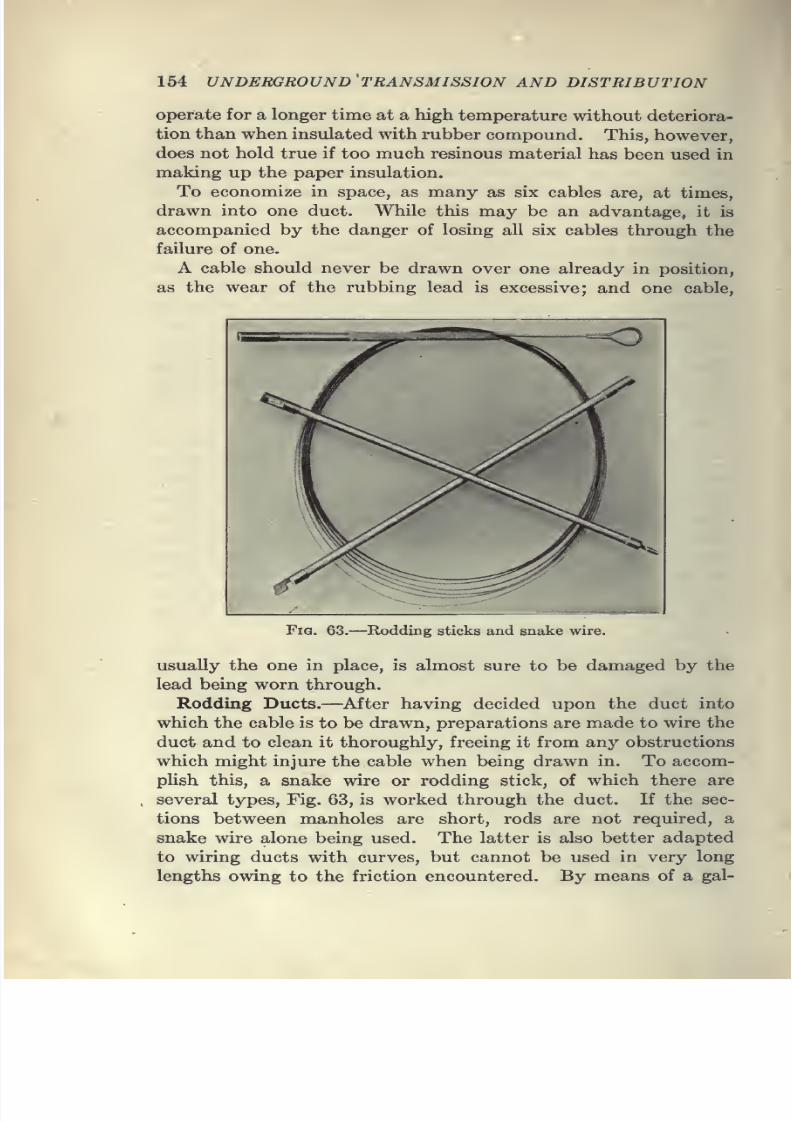
7/28/2019 Underground Trans 00 Me Yeu of t
http://slidepdf.com/reader/full/underground-trans-00-me-yeu-of-t 166/327
154 underground'transmission and distribution
operate for a longer time at a high temperature without deteriora-
tion than when insulated with rubber compound. This, however,
does not hold true if too much resinous material has been used in
making up the paper insulation.
To economize in space, as many as six cables are, at times,
drawn into one duct. While this may be an advantage, it is
accompanied by the danger of losing all six cables through the
failure of one.
A cable should never be drawn over one already in position,
as the wear of the rubbing lead is excessive; and one cable,
Fia. 63.—Rodding sticks and snake wire.
usually the one in place, is almost sure to be damaged by the
lead being worn through.
Rodding Ducts.—After having decided upon the duct into
which the cable is to be drawn, preparations are made to wire the
duct and to clean it thoroughly, freeing it from any obstructions
which might injure the cable when being drawn in. To accom-
plish this, a snake wire or rodding stick, of which there are
several types. Fig. 63, is worked through the duct. If the sec-
tions between manholes are short, rods are not required, a
snake wire alone being used. The latter is also better adapted
to wiring ducts with curves, but cannot be used in very long
lengths owing to the friction encountered. By means of a gal-
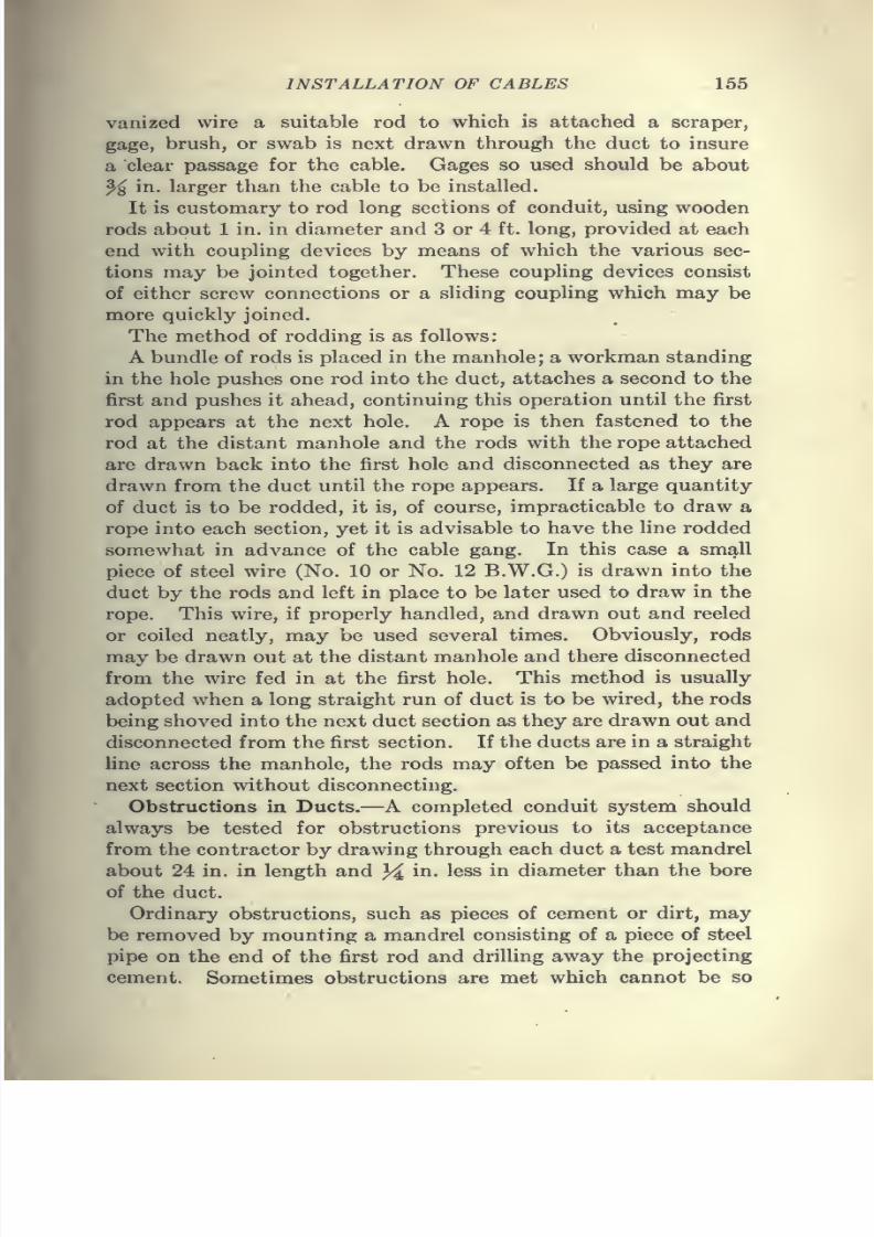
7/28/2019 Underground Trans 00 Me Yeu of t
http://slidepdf.com/reader/full/underground-trans-00-me-yeu-of-t 167/327
INSTALLATION OF CABLES 155
vanized wire a suitable rod to which is attached a scraper,
gage, brush, or swab is next drawn through the duct to insure
a clear passage for the cable. Gages so used should be about% in. larger than the cable to be installed.
It is customary to rod long sections of conduit, using wooden
rods about 1 in, in diameter and 3 or 4 ft. long, provided at each
end with coupling devices by means of which the various sec-
tions may be jointed together. These coupling devices consist
of either screw connections or a sliding coupling which may be
more quickly joined.
The method of rodding is as follows:
A bundle of rods is placed in the manhole; a workman standing
in the hole pushes one rod into the duct, attaches a second to the
first and pushes it ahead, continuing this operation until the first
rod appears at the next hole. A rope is then fastened to the
rod at the distant manhole and the rods with the rope attached
are drawn back into the first hole and disconnected as they are
drawn from the duct until the rope appears. If a large quantity
of duct is to be rodded, it is, of course, impracticable to draw a
rope into each section, yet it is advisable to have the line rodded
somewhat in advance of the cable gang. In this case a small
piece of steel wire (No. 10 or No. 12 B.W.G.) is drawn into the
duct by the rods and left in place to be later used to draw in the
rope. This wire, if properly handled, and drawn out and reeled
or coiled neatly, may be used several times. Obviously, rods
may be drawn out at the distant manhole and there disconnected
from the wire fed in at the first hole. This method is usually
adopted when a long straight run of duct is to be wired, the rods
being shoved into the next duct section as they are drawn out and
disconnected from the first section. If the ducts are in a straight
Une across the manhole, the rods may often be passed into the
next section without disconnecting.
Obstructions in Ducts.—A completed conduit system should
always be tested for obstructions previous to its acceptance
from the contractor by drawing through each duct a test mandrel
about 24 in. in length and ^ in. less in diameter than the bore
of the duct.
Ordinary obstructions, such as pieces of cement or dirt, may
be removed by mounting a mandrel consisting of a piece of steel
pipe on the end of the first rod and drilling away the projecting
cement. Sometimes obstructions are met which cannot be so
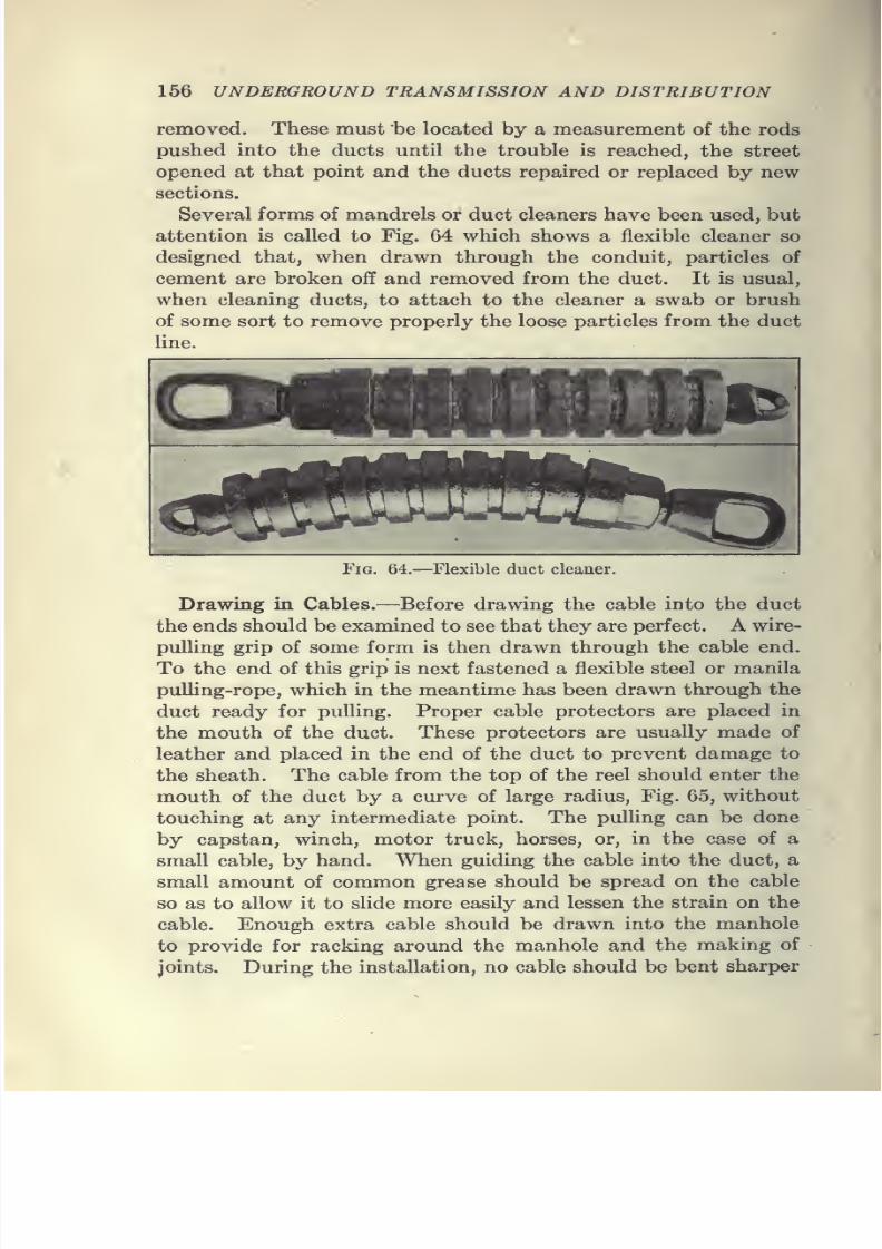
7/28/2019 Underground Trans 00 Me Yeu of t
http://slidepdf.com/reader/full/underground-trans-00-me-yeu-of-t 168/327
156 UNDERGROUND TRANSMISSION AND DISTRIBUTION
removed. These must be located by a measurement of the rods
pushed into the ducts until the trouble is reached, the street
opened at that point and the ducts repaired or replaced by newsections.
Several forms of mandrels or duct cleaners have been used, but
attention is called to Fig. 64 which shows a flexible cleaner so
designed that, when drawn through the conduit, particles of
cement are broken off and removed from the duct. It is usual,
when cleaning ducts, to attach to the cleaner a swab or brush
of some sort to remove properly the loose particles from the duct
line.
^^^^HHHHwww^
Fig. 64.—Flexible duct cleaner.
Drawing in Cables.—Before drawing the cable into the duct
the ends should be examined to see that they are perfect. A wire-
pulling grip of some form is then drawn through the cable end.
To the end of this grip is next fastened a flexible steel or manila
pulling-rope, which in the meantime has been drawn through theduct ready for pulling. Proper cable protectors are placed in
the mouth of the duct. These protectors are usually made of
leather and placed in the end of the duct to prevent damage to
the sheath. The cable from the top of the reel should enter the
mouth of the duct by a curve of large radius. Fig. 65, without
touching at any intermediate point. The pulling can be done
by capstan, winch, motor truck, horses, or, in the case of a
small cable, by hand. When guiding the cable into the duct, a
small amount of common grease should be spread on the cable
so as to allow it to slide more easily and lessen the strain on the
cable. Enough extra cable should be drawn into the manhole
to provide for racking around the manhole and the making of
joints. During the installation, no cable should be bent sharper
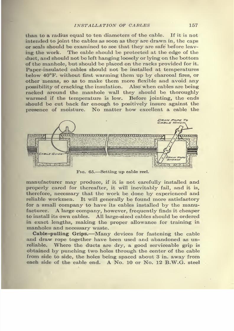
7/28/2019 Underground Trans 00 Me Yeu of t
http://slidepdf.com/reader/full/underground-trans-00-me-yeu-of-t 169/327
INSTALLATION OF CABLES 157
than to a radius equal to ten diameters of the cable. If it is not
intended to joint the cables as soon as they are drawn in, the caps
or seals should be examined to see that they are safe before leav-
ing the work. The cable should be protected at the edge of the
duct, and should not be left hanging loosely or lying on the bottom
of the manhole, but should be placed on the racks provided for it.
Paper-insulated cables should not be installed at temperatures
below 40°F. without first warming them up by charcoal fires, or
other means, so as to make them more flexible and avoid any
possibility of cracking the insulation. Also when cables are being
racked around the manhole wall they should be thoroughly
warmed if the temperature is low. Before jointing, the ends
should be cut back far enough to positively insure against the
presence of moisture. No matter how excellent a cable the
/?/*/« IV /Po^jr To
Fig. 65.—Setting up cable reel.
manufacturer may produce, if it is not carefully installed and
properly cared for thereafter, it will inevitably fail, and it is,
therefore, necessary that the work be done by experienced and
reliable workmen. It will generally be found more satisfactory
for a small company to have its cables installed by the manu-
facturer. A large company, however, frequently finds it cheaper
to install its own cables. All large-sized cables should be ordered
in exact lengths, making the proper allowance for training in
manholes and necessary waste.
Cable-pulling Grips.—Many devices for fastening the cable
and draw rope together have been used and abandoned as un-
reliable. Where the ducts are dry, a good serviceable grip is
obtained by punching two holes through the center of the cable
from side to side, the holes being spaced about 3 in. away from
each side of the cable end. A No. 10 or No. 12 B.W.G. steel
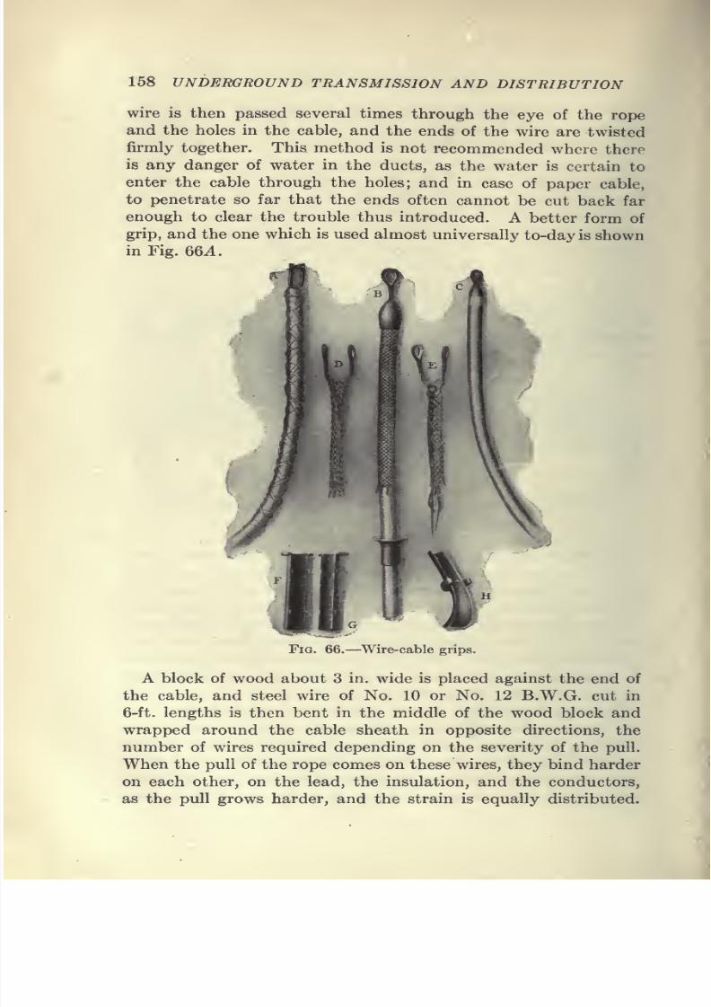
7/28/2019 Underground Trans 00 Me Yeu of t
http://slidepdf.com/reader/full/underground-trans-00-me-yeu-of-t 170/327
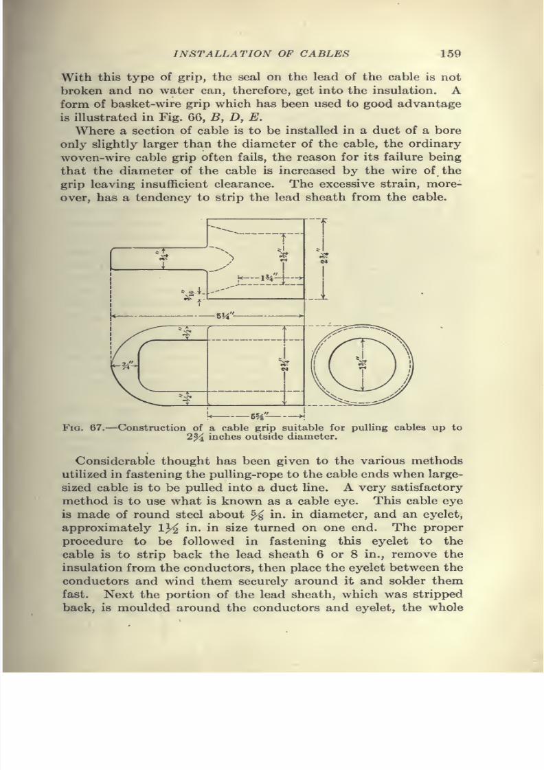
7/28/2019 Underground Trans 00 Me Yeu of t
http://slidepdf.com/reader/full/underground-trans-00-me-yeu-of-t 171/327
INSTALLATION OF CABLES 159
With this type of grip, the seal on the lead of the cable is not
broken and no water can, therefore, get into the insulation. A
form of basket-wire grip which has been used to good advantageis illustrated in Fig. 66, B, D, E.
Where a section of cable is to be installed in a duct of a bore
only slightly larger than the diameter of the cable, the ordinary
woven-wire cable grip often fails, the reason for its failure being
that the diameter of the cable is increased by the wire of the
grip leaving insufficient clearance. The excessive strain, more-
over, has a tendency to strip the lead sheath from the cable.
Fig. 67.—Construction of a cable grip suitable for pulling cables up to2% inches outside diameter.
Considerable thought has been given to the various methods
utilized in fastening the pulling-rope to the cable ends when large-
sized cable is to be pulled into a duct line. A very satisfactory
method is to use what is known as a cable eye. This cable eye
is made of round steel about % in. in diameter, and an eyelet,
approximately IY2 in. in size turned on one end. The proper
procedure to be followed in fastening this eyelet to the
cable is to strip back the lead sheath 6 or 8 in., remove the
insulation from the conductors, then place the eyelet between the
conductors and wind them securely around it and solder them
fast. Next the portion of the lead sheath, which was stripped
back, is moulded around the conductors and eyelet, the whole
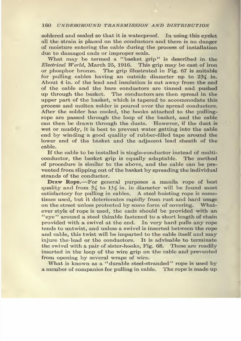
7/28/2019 Underground Trans 00 Me Yeu of t
http://slidepdf.com/reader/full/underground-trans-00-me-yeu-of-t 172/327
160 UNDERGROUND TRANSMISSION AND DISTRIBUTION
soldered and sealed so that it is waterproof. In using this eyelet
all the strain is placed on the conductors and there is no danger
of moisture entering the cable during the process of installation
due to damaged ends or improper seals.
What may be termed a "basket grip" is described in the
Electrical World, March 25, 1916. This grip may be cast of iron
or phosphor bronze. The grip illustrated in Fig. 67 is suitable
for pulling cables having an outside diameter up to 2^ in.
About 4 in. of the lead and insulation is cut away from the end
of the cable and the bare conductors are tinned and pushed
up through the basket. The conductors are then spread in theupper part of the basket, which is tapered to accommodate this
process and molten solder is poured over the spread conductors.
After the solder has cooled, the hooks attached to the puUing-
rope are passed through the loop of the basket, and the cable
can then be drawn through the ducts. However, if the duct is
wet or muddy, it is best to prevent water getting into the cable
end by winding a good quality of rubber-filled tape around the
lower end of the basket and the adjacent lead sheath of thecable.
If the cable to be installed is single-conductor instead of multi-
conductor, the basket grip is equally adaptable. The method
of procedure is similar to the above, and the cable can be pre-
vented from slipping out of the basket by spreading the individual
strands of the conductor.
Draw Rope.—For general purposes a manila rope of best
quality and from
^to
1}4in. in diameter will be found most
satisfactory for pulling in cables. A steel hoisting rope is some-
times used, but it deteriorates rapidly from rust and hard usage
on the street unless protected by some form of covering. What-
ever style of rope is used, the ends should be provided with an
"eye" around a steel thimble fastened to a short length of chain
provided with a swivel at the end. In very hard pulls any rope
tends to untwist, and unless a swivel is inserted between the rope
and cable, this twist will be imparted to the cable itself and may
injure the- lead or the conductors. It is advisable to terminate
the swivel with a pair of sister-hooks. Fig. 68. These are readily
inserted in the loop of the wire grip on the cable and prevented
from opening by several wraps of wire.
What is known as a "durable steel-stranded" rope is used by
a number of companies for pulling in cable. The rope is made up
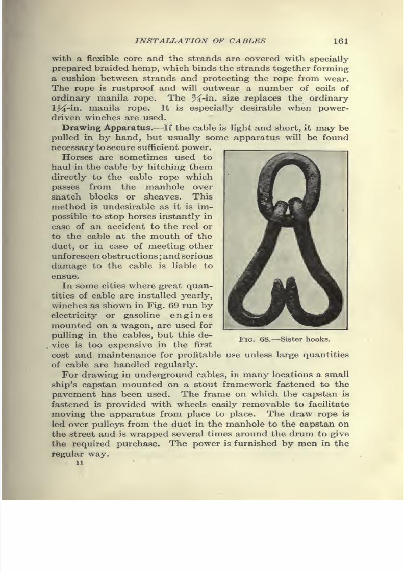
7/28/2019 Underground Trans 00 Me Yeu of t
http://slidepdf.com/reader/full/underground-trans-00-me-yeu-of-t 173/327
INSTALLATION OF CABLES 161
with a flexible core and the strands are covered with specially
prepared braided hemp, which binds the strands together forming
a cushion between strands and protecting the rope from wear.The rope is rustproof and will outwear a number of coils of
ordinary manila rope. The %-in. size replaces the ordinary
13^-in. manila rope. It is especially desirable when power-
driven winches are used.
Drawing Apparatus.—If the cable is light and short, it may be
pulled in by hand, but usually some apparatus will be found
necessary to secure sufficient power.
Horses are sometimes used tohaul in the cable by hitching them
directly to the cable rope which
passes from the manhole over
snatch blocks or sheaves. This
method is undesirable as it is im-
possible to stop horses instantly in
case of an accident to the reel or
to the cable at the mouth of theduct, or in case of meeting other
unforeseen obstructions; and serious
damage to the cable is liable to
ensue.
In some cities where great quan-
tities of cable are installed yearly,
winches as shown in Fig. 69 run by
electricity or gasoline
enginesmounted on a wagon, are used for
pulling in the cables, but this de-
vice is too expensive in the first
cost and maintenance for profitable use unless large quantities
of cable are handled regularly.
For drawing in underground cables, in many locations a small
ship's capstan mounted on a stout framework fastened to the
pavement has been used. The frame on which the capstan is
fastened is provided with wheels easily removable to facilitate
moving the apparatus from place to place. The draw rope is
led over pulleys from the duct in the manhole to the capstan on
the street and is wrapped several times around the drum to give
the required purchase. The power is furnished by men in the
regular way.
11
Fig. 68.—Sister hooks.
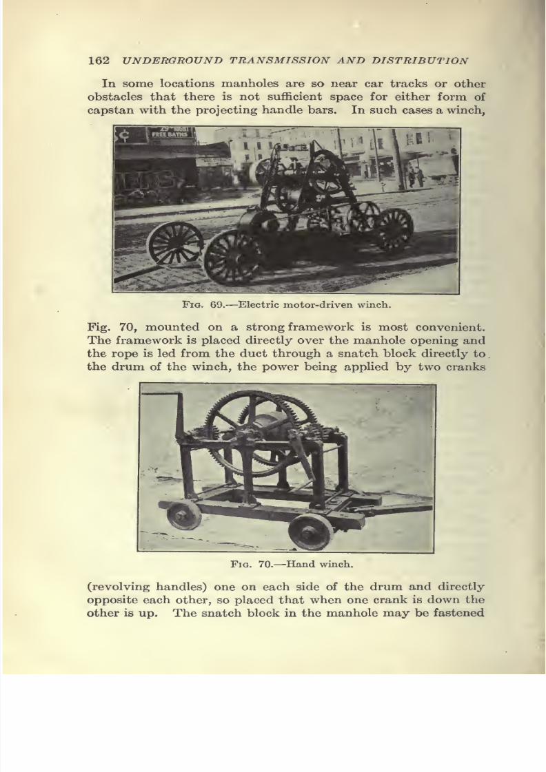
7/28/2019 Underground Trans 00 Me Yeu of t
http://slidepdf.com/reader/full/underground-trans-00-me-yeu-of-t 174/327
162 UNDERGROUND TRANSMISSION AND DISTRIBUTION
In some locations manholes are so near car tracks or other
obstacles that there is not sufficient space for either form of
capstan with the projecting handle bars. In such cases a winch,
Fig. 69.—Electric motor-driven winch.
Fig. 70, mounted on a strong framework is most convenient.
The framework is placed directly over the manhole opening and
the rope is led from the duct through a snatch block directly to
.
the drum of the winch, the power being applied by two cranks
Fig. 70.—Hand winch.
(revolving handles) one on each side of the drum and directly
opposite each other, so placed that when one crank is down the
other is up. The snatch block in the manhole may be fastened
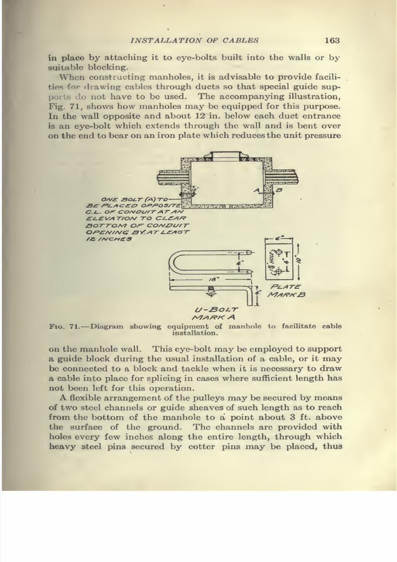
7/28/2019 Underground Trans 00 Me Yeu of t
http://slidepdf.com/reader/full/underground-trans-00-me-yeu-of-t 175/327
INSTALLATION OF CABLES 163
in place by attaching it to eye-bolts built into the walls or by
suitable blocking.
When constructing manholes, it is advisable to provide facili-
ties for drawing cables through ducts so that special guide sup-
ports do not have to be used. The accompanying illustration,
Fig. 71, shows how manholes may be equipped for this purpose.
In the wall opposite and about 12 in. below each duct entrance
is an eye-bolt which extends through the wall and is bent over
on the end to bear on an iron plate which reduces the unit pressure
0/V£^ BOCT fA)TO
CU. Of=- CONOU/TAT/IA/£l.£VAT/OA/ TO CL.£Af?
SOTTO/V7 0/=" COA/I?i//T
r'
EHEB-T4
19'
^J
-y^r-
\
\
Fig. 71.—Diagram showing
U~J50i.T
equipment of manhole
installation.
f*^/iT£
to facilitate cable
on the manhole wall. This eye-bolt may be employed to support
a guide block during the usual installation of a cable, or it may
be connected to a block and tackle when it is necessary to draw
a cable into place for splicing in cases where sufficient length has
not been left for this operation.
A flexible arrangement of the pulleys may be secured by means
of two steel channels or guide sheaves of such length as to reach
from the bottom of the manhole to a point about 3 ft. above
the surface of the ground. The channels are provided with
holes every few inches along the entire length, through which
heavy steel pins secured by cotter pins may be placed, thus
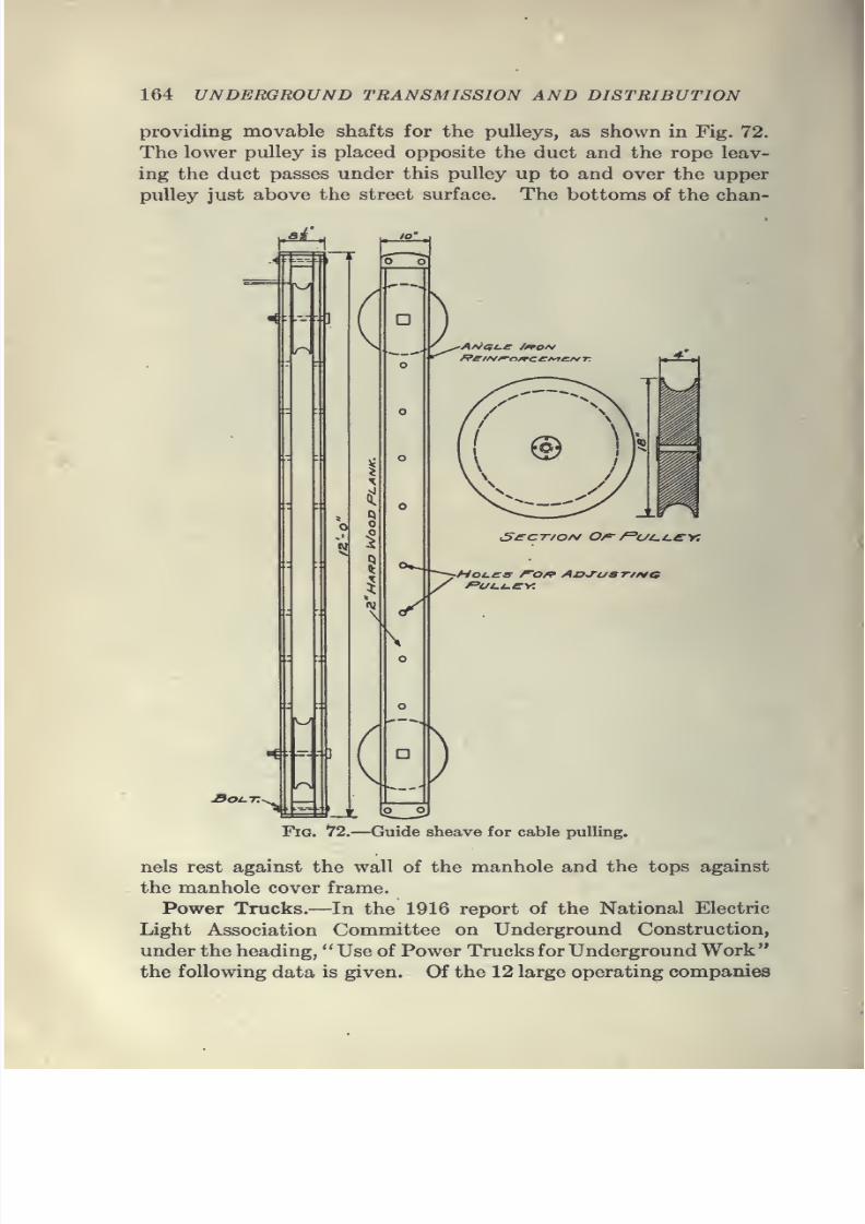
7/28/2019 Underground Trans 00 Me Yeu of t
http://slidepdf.com/reader/full/underground-trans-00-me-yeu-of-t 176/327
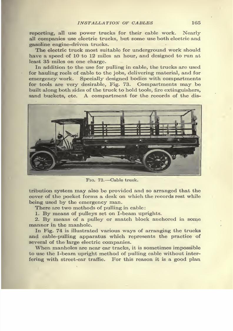
7/28/2019 Underground Trans 00 Me Yeu of t
http://slidepdf.com/reader/full/underground-trans-00-me-yeu-of-t 177/327
INSTALLATION OF CABLES 165
reporting, all use power trucks for their cable work. Nearly
all companies use electric trucks, but some use both electric and
gasoline engine-driven trucks.The electric truck most suitable for underground work should
have a speed of 10 to 12 miles an hour, and designed to run at
least 35 miles on one charge.
In addition to the use for pulling in cable, the trucks are used
for hauling reels of cable to the jobs, delivering material, and for
emergency work. Specially designed bodies with compartments
for tools are very desirable, Fig. 73. Compartments may be
builtalong both
sides ofthe truck
to hold tools, fire extinguishers,
sand buckets, etc. A compartment for the records of the dis-
FiG. 73.—Cable truck.
tribution system may also be provided and so arranged that the
cover of the pocket forms a desk on which the records rest while
being used by the emergency man.
There are two methods of pulling in cable:
1. By means of pulleys set on I-beam uprights.
2. By means of a pulley or snatch block anchored in some
manner in the manhole.
In Fig. 74 is illustrated various ways of arranging the trucks
and cable-pulling apparatus which represents the practice of
several of the large electric companies.
When manholes are near car tracks, it is sometimes impossible
to use the I-beam upright method of pulling cable without inter-
fering with street-car traffic. For this reason it is a good plan
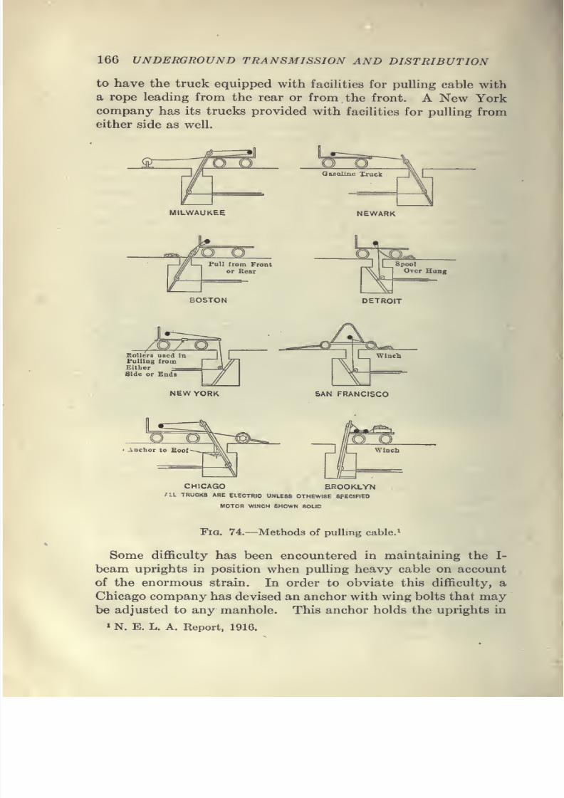
7/28/2019 Underground Trans 00 Me Yeu of t
http://slidepdf.com/reader/full/underground-trans-00-me-yeu-of-t 178/327
7/28/2019 Underground Trans 00 Me Yeu of t
http://slidepdf.com/reader/full/underground-trans-00-me-yeu-of-t 179/327
7/28/2019 Underground Trans 00 Me Yeu of t
http://slidepdf.com/reader/full/underground-trans-00-me-yeu-of-t 180/327
168 UNDERGROUND TRANSMISSION AND DISTRIBUTION
repeat the operation until sufficient cable has been secured.
Always determine the location of the splice in the manhole and
provide the foreman of the drawing-in gang with a diagram and
list showing exactly how much cable should project from the
duct into the manhole at each end of each section.
After a cable has been drawn in, an experienced workman
should examine the ends to see if the solder seal is intact or, if
broken, whether any moisture is present. If moisture is dis-
cernible, boil it out thoroughly or (if enough stock is available)
cut back the cable until all dampness is removed; and in all cases
leave the end carefully soldered up.
The cable should be protected at the edge of the duct, and it
should not be left hanging loosely or lying on the bottom of
the manhole, but should be placed on the racks provided for it.
If .the cables have paper insulation and the temperature is below
40°F., they should be warmed by torch or other means, so as to
make them more flexible and avoid any possibiHty of cracking the
insulation when the cables are being racked around the manhole
walls.
Jointing of Cables.—It is generally admitted that the greater
part of cable trouble is due to poorly made joints or to the
presence of moisture or cracks in the insulation near the joints.
With good material and careful and competent workmen, the
insulation of the joint can be made as rehable and as durable
as that of any part of the cable. The construction of a joint
is, therefore, of prime importance, and unless the engineer has
at his command experienced and thoroughly reliable cable work-men, he would do well to contract with the manufacturers, who
have every facility for doing this class of work, for the complete
installation of the cable.
In the making of a perfect joint, the following points are
especially worthy of comment and caution
(a) The work should be done by reliable and experienced
cablemen.
(6) High-grade insulating materials should be carefully chosen
to suit the special conditions.
(c) Every trace of moisture should be excluded from the
joint and adjacent parts of the cable.
(d) The layers of insulating tape should be made to overlap
each other and should be drawn tight to exclude air.
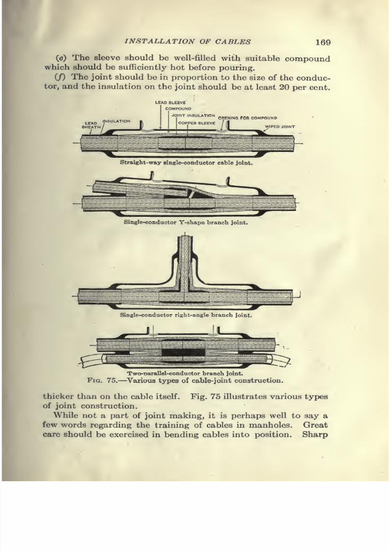
7/28/2019 Underground Trans 00 Me Yeu of t
http://slidepdf.com/reader/full/underground-trans-00-me-yeu-of-t 181/327
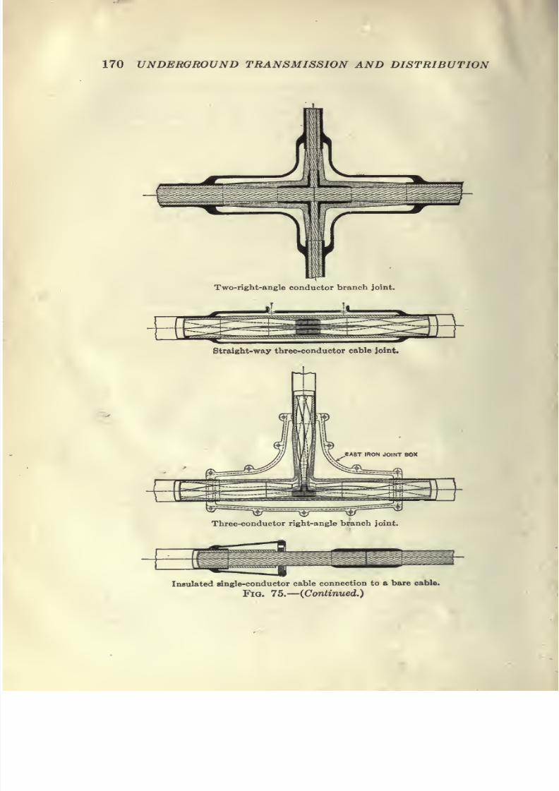
7/28/2019 Underground Trans 00 Me Yeu of t
http://slidepdf.com/reader/full/underground-trans-00-me-yeu-of-t 182/327
7/28/2019 Underground Trans 00 Me Yeu of t
http://slidepdf.com/reader/full/underground-trans-00-me-yeu-of-t 183/327
7/28/2019 Underground Trans 00 Me Yeu of t
http://slidepdf.com/reader/full/underground-trans-00-me-yeu-of-t 184/327
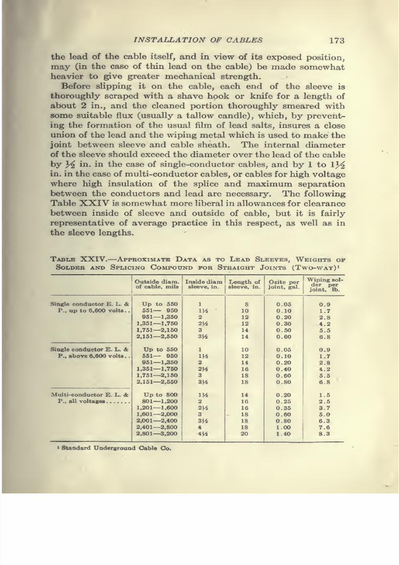
7/28/2019 Underground Trans 00 Me Yeu of t
http://slidepdf.com/reader/full/underground-trans-00-me-yeu-of-t 185/327
INSTALLATION OF CABLES 173
the lead of the cable itself, and in view of its exposed position,
may (in the case of thin lead on the cable; be made somewhat
heavier to give greater mechanical strength.Before slipping it on the cable, each end of the sleeve is
thoroughly scraped with a shave hook or knife for a length of
about 2 in., and the cleaned portion thoroughly smeared with
some suitable flux (usually a tallow candle), which, by prevent-
ing the formation of the usual film of lead salts, insures a close
imion of the lead and the wiping metal which is used to make the
joint between sleeve and cable sheath. The internal diameter
of the sleeve should exceed the diameter over the lead of the cableby 3^ in. in the case of single-conductor cables, and by 1 to 1}4
in. in the case of multi-conductor cables, or cables for high voltage
where high insulation of the splice and maximum separation
between the conductors and lead are necessary. The following
Table XXIV is somewhat more liberal in allowances for clearance
between inside of sleeve and outside of cable, but it is fairly
representative of average practice in this respect, as well as in
the sleeve lengths.
Table XXIV. Approximate Data as to Lead Sleeves, Weights of
SOLDEB AND SpLICINQ COMPOUND FOR STRAIGHT JoiNTS (TwO-WAY)'
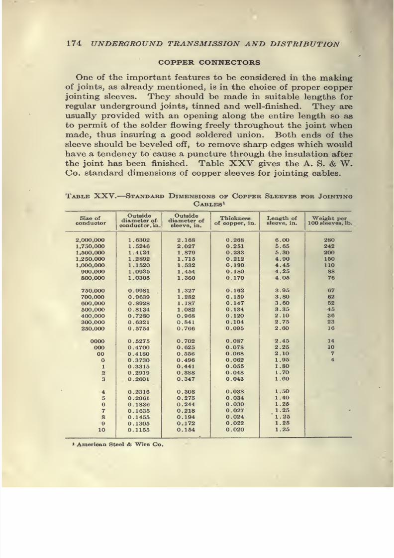
7/28/2019 Underground Trans 00 Me Yeu of t
http://slidepdf.com/reader/full/underground-trans-00-me-yeu-of-t 186/327
7/28/2019 Underground Trans 00 Me Yeu of t
http://slidepdf.com/reader/full/underground-trans-00-me-yeu-of-t 187/327
7/28/2019 Underground Trans 00 Me Yeu of t
http://slidepdf.com/reader/full/underground-trans-00-me-yeu-of-t 188/327
176 UNDERGROUND TRANSMISSION AND DISTRIBUTION
concentric with the cable. The sleeve and the cables are then
joined by a wiped solder joint.
FILLING THE SLEEVE
The joint is next filled with hot compound, except in the case
of rubber-insulated cables. Two holes are tapped in the sleeve,
hot insulation is poured slowly in one hole until it appears at the
other, and then in each hole alternately until the joint is com-
pletely filled.
If any moisture appears in the joint, as shown by frothing of
the insulation, the compound should be allowed to flow freely
out of one hole until all moisture is removed.
The joint should be allowed to cool for a suitable period
before moving it, and any shrinkage or settling of the insulation
should be compensated for by the addition of more compound.
This is a particularly important point in the splicing of high-
tension cables, and should be carefully watched.
Jointing Rubber-insulated Cables.—The splices on rubber-
insulated cables differ from splices on other forms of cable only
in the kind of tapes used.
The wire splice is made precisely as hereinbefore described.
This splice is then covered by a layer or layers of pure rubber
tape spirally applied to a thickness of ^4 to }/s2 ^^' This is
covered by rubber-compound tapes applied spirally until a total
thickness slightly greater than the insulation of the cable is
secured. Over all is placed a layer of linen tape thoroughly im-
pregnated with rubber to render it adhesive. The lead joint is
then made in the regular manner, but is not filled with hot
compound. In some instances it is necessary to vulcanize thor-
oughly the rubber tapes so as to cure the rubber and render it
homogeneous, elastic and water-tight. This process should be
entrusted only to experts.
Jointing Armored Cables.—When lead-covered cables are
provided with steel-wire armor, a joint in the armor wires is
required in addition to the joint on the cable, the latter beingmade in the regular manner. While making the lead-covered
joint, the armor wires should be bound by tie wire on either side,
and bent back out of the way. When the cable is spliced and
the lead joint completed, the cable should be protected with
wrappings of jute over the lead sleeve and the armor wires, from

7/28/2019 Underground Trans 00 Me Yeu of t
http://slidepdf.com/reader/full/underground-trans-00-me-yeu-of-t 189/327
INSTALLATION OF CABLES 177
one side, bent down and spaced uniformly over the sleeve. The
sleeve being larger than the original cable, there will be space
between the armor wires, and these are filled by the armor wiresfrom the other side of the joint, the two sets of wires being
thus interlaced. If there is not space enough between the wires
from one side for all the wires from the other, the surplus wires
are cut off short on one section and the corresponding wires on
the other section left long enough to butt against the short wires,
thus covering the joint completely and evenly with the armor
wires. Where the armor wires are thus placed, they are firmly
boundtogether
by atight serving of wires
woundin
ashort
spiral around the entire length of the splice and carefully soldered
to the armor. A joint thus made will be mechanically as strong
as any other part of the cable.
As the durability of a joint is dependent upon the proper exe-
cution of what might seem to be the most minute details, a
description of some of the methods of making up joints on three-
conductor paper cables is printed herewith.
Paper and Cambric Tape-insulated Joints.
—The ends of the
cable are prepared in the usual manner by stripping off the lead.
The paper insulation is trimmed away to expose the conductors.
Split copper sleeves are slipped over the conductors that are to
be joined and the sleeve is then sweated on with solder. No
acid should be used as a flux in soldering, as it is likely to injure
the insulation.
The insulation on the conductors on each side of the sleeve
should be cut down to a pencil point so as to allow the tape to be
built up evenly without butt joints. The best work that can
be done by hand will be considerably looser than the machine-
wrapped insulation on the main cable, and for that reason the
tape should be put on thicker than the original insulation. In
applying tape on cables used for voltages over 10,000, a suitable
compound should be applied with a brush to each layer of tape.
This will tend to prevent the formation of air cells which invari-
ably accompany the taping of a joint and which have been found
to impair seriously the insulation of a high-voltage joint. During
the progress of the wrapping, the insulation should be boiled out
thoroughly by pouring hot compound over the layers of tape to
exclude all moisture. Moisture from the hands of the splicer
may be sufficient to destroy an otherwise perfect joint.
After all conductors are thoroughly taped and boiled out, a
12
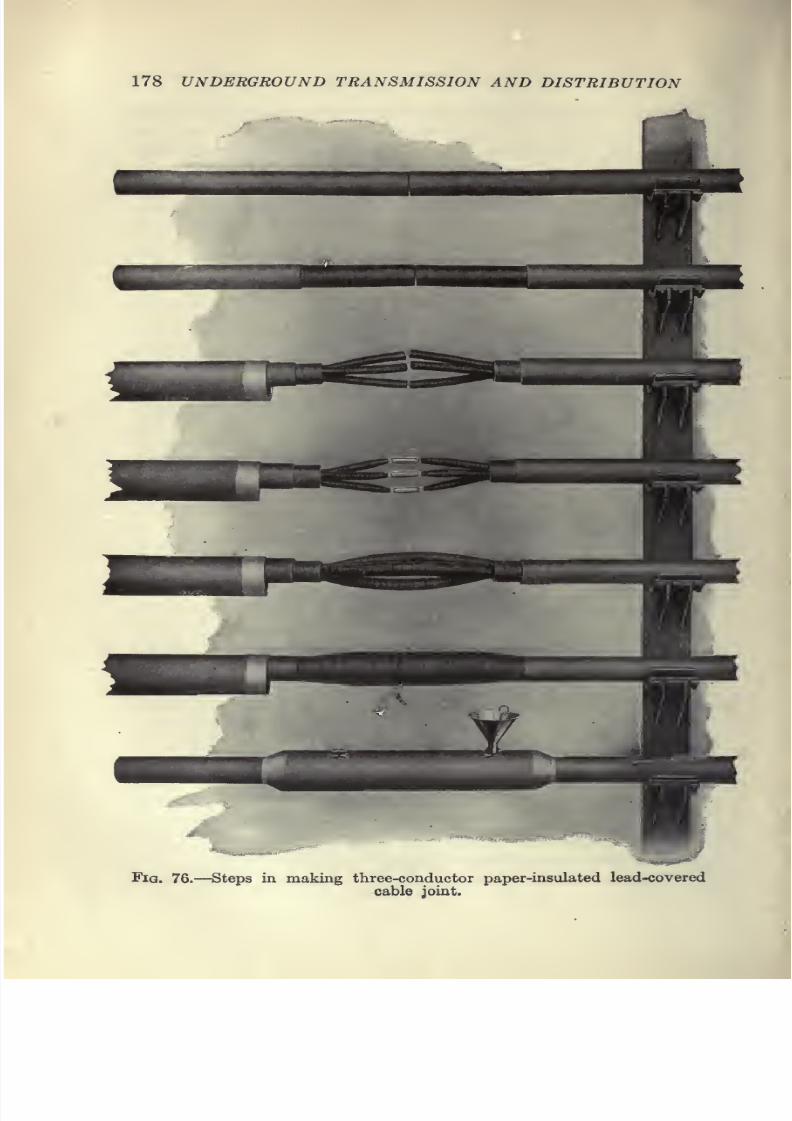
7/28/2019 Underground Trans 00 Me Yeu of t
http://slidepdf.com/reader/full/underground-trans-00-me-yeu-of-t 190/327
7/28/2019 Underground Trans 00 Me Yeu of t
http://slidepdf.com/reader/full/underground-trans-00-me-yeu-of-t 191/327
INSTALLATION OF CABLES 179
small roll of tape should be placed between the conductors to
separate them. An outer wrapping of tape should be applied,
which is drawn tight and wrapped until it is considerably larger
than the original insulation but not too large to permit the lead
sleeve to be placed over it. Numerous incisions are then made
in the outer wrapping in order to allow the compound to fill up
all the voids on the inside. Great care must be taken in punch-
ing these holes not to injure the insulation on the individual
conductors.
The lead sleeve which has previously been prepared and
placed over one of the cable ends, is now beaten into proper
form and placed evenly over the joint. The sleeve is then
soldered to the cable sheath with a regular wiped joint. The
wipes must be absolutely water-tight and should be carefully
inspected, especially on the underside of the joint, by means
of a small mirror to insure smoothness, solidity, and absence of
air holes. This is most important as the presence of small blow-
holes is known to have caused perhaps more trouble than any
other feature in joint making. The various steps in the makingof a three-conductor high-tension cable joint are fully illustrated
in Fig. 76.
For filling the joint, two holes are punched in the top of the
lead sleeve about 3 in. from each end, one to pour compound
through and the other to serve as an air vent. The compound
should be poured very hot and the pouring continued until the
compound overflows at the opposite end. After standing for
half an hour or more, the sleeve is refilled, after which theopenings in the sleeve are sealed by soldering a small lead patch
over each.
Paper-tube Joints.—The Standard Underground Cable Co.
recommend the following procedure for making high-voltage
paper-tube joints:
Cut off ends of cable square. Cut off lead on one cable at a
point approximately 6 in. back from end; and on the other cable
approximately 9 in. back from end. (Caution.—The longi-
tudinal cut in lead should be made by inserting cutting knife
tangential with the inside curve of the lead sheathing. Circum-
ferential cut should be made by nicking lead only part way
through and then tearing by pulling it apart with pliers.) Re-
move belt insulation to a point about 1}4 in. from edge of lead.
(Caution.—Inner layers of paper of belt should be torn rather
7/28/2019 Underground Trans 00 Me Yeu of t
http://slidepdf.com/reader/full/underground-trans-00-me-yeu-of-t 192/327

7/28/2019 Underground Trans 00 Me Yeu of t
http://slidepdf.com/reader/full/underground-trans-00-me-yeu-of-t 193/327
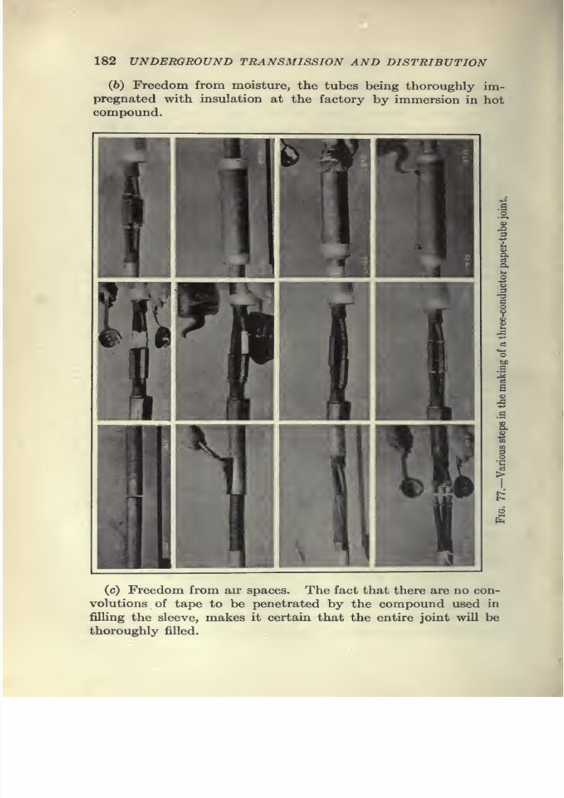
7/28/2019 Underground Trans 00 Me Yeu of t
http://slidepdf.com/reader/full/underground-trans-00-me-yeu-of-t 194/327
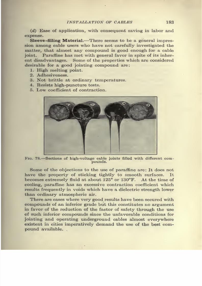
7/28/2019 Underground Trans 00 Me Yeu of t
http://slidepdf.com/reader/full/underground-trans-00-me-yeu-of-t 195/327
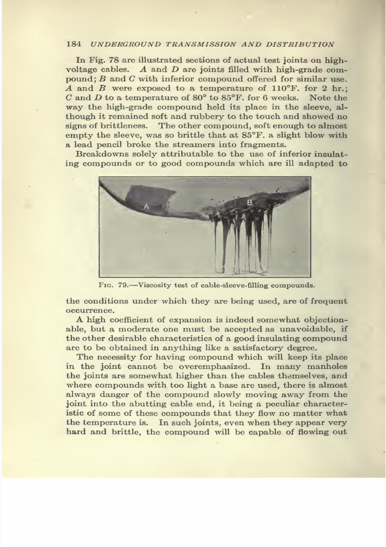
7/28/2019 Underground Trans 00 Me Yeu of t
http://slidepdf.com/reader/full/underground-trans-00-me-yeu-of-t 196/327
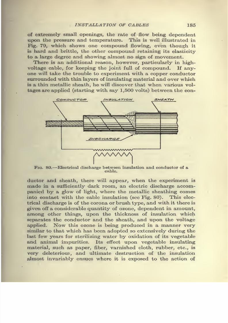
7/28/2019 Underground Trans 00 Me Yeu of t
http://slidepdf.com/reader/full/underground-trans-00-me-yeu-of-t 197/327
INSTALLATION OF CABLES 185
of extremely small openings, the rate of flow being dependent
upon the pressure and temperature. This is well illustrated in
Fig. 79, which shows one compound flowing, even though it
is hard and brittle, the other compound retaining its elasticity
to a large degree and showing almost no sign of movement.
There is an additional reason, however, particularly in high-
voltage cable, for keeping the joint full of compound. If any-
one will take the trouble to experiment with a copper conductor
surrounded with thin layers of insulating material and over which
is a thin metallic sheath, he will discover that when various vol-
tages are applied (starting with say 1,500 volts) between the con-
CONOUCTOf^ /A/SUi-A 7-/OA/ SHEATM
Fig. 80.—Electrical discharge between insulation and conductor of a
cable.
ductor and sheath, there will appear, when the experiment is
made in a sufficiently dark room, an electric discharge accom-
panied by a glow of light, where the metallic sheathing comes
into contact with the cable insulation (see Fig. 80). This elec-
trical discharge is of the corona or brush type, and with it there is
given off a considerable quantity of ozone, dependent in amount,
among other things, upon the thickness of insulation which
separates the conductor and the sheath, and upon the voltage
applied. Now this ozone is being produced in a manner very
similar to that which has been adopted so extensively during the
last few years for sterilizing water by oxidation of its vegetable
and animal impurities. Its effect upon vegetable insulating
material, such as paper, fiber, varnished cloth, rubber, etc., is
very deleterious, and ultimate destruction of the insulation
almost invariably ensues where it is exposed to the action of
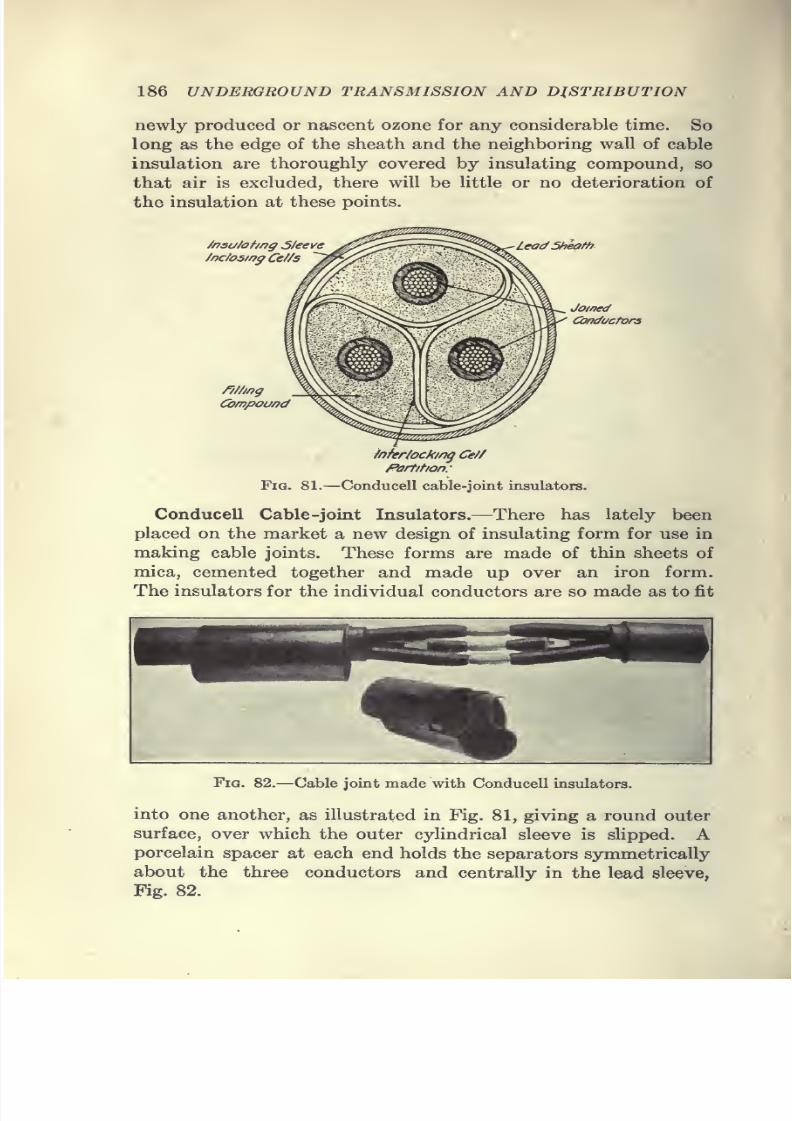
7/28/2019 Underground Trans 00 Me Yeu of t
http://slidepdf.com/reader/full/underground-trans-00-me-yeu-of-t 198/327
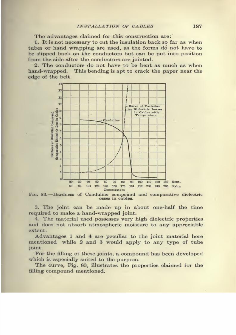
7/28/2019 Underground Trans 00 Me Yeu of t
http://slidepdf.com/reader/full/underground-trans-00-me-yeu-of-t 199/327
7/28/2019 Underground Trans 00 Me Yeu of t
http://slidepdf.com/reader/full/underground-trans-00-me-yeu-of-t 200/327
7/28/2019 Underground Trans 00 Me Yeu of t
http://slidepdf.com/reader/full/underground-trans-00-me-yeu-of-t 201/327
INSTALLATION OF CABLES 189
Experiments have been made on a joint insulated with liquid
fillers, such as rosin or mineral oil, which are fluid at low tempera-
tures. These joints gave uniformly good results, but some diffi-
culty was experienced from the leaking of the oil from the joint
space along the cables. This difficulty was overcome after con-
siderable experimenting; and a very satisfactory high-voltage
joint has been designed and patented by Mr. Philip Torchio,
chief electrical engineer of the New York Edison Co.
In making this joint the cutting of the insulation and the
application of new insulation conforms to a special gage which
is part of the cable-splicers' equipment. The lead sheath is
stripped off in the usual way preparatory to jointing. After
the conductors are soldered, all metal points and burrs are re-
moved by filing and with emery cloth, and the space between the
conductors is thoroughly cleansed of all particles of emery and
copper. A liberal application of compound is given to the con-
ductor to be insulated, and impregnated-paper tape % in. wide
and 3 mils thick is wrapped tightly around it. Each layer of tape
receives an application of compound before the next is applied
and each turn of the tape is drawn tight so as to squeeze out any
air bubbles which might collect in the space between the layers.
The hand-applied insulation at its thickest point is about one and
one-quarter times that of the mill-applied insulation.
After each of the three conductors has received its applied
insulation, the space between the conductors is filled with com-
pound, and strips of jute, laid parallel to the conductors, are
packed into the space so as to completely fill it ; and the whole is
then saturated with compound. The belt insulation of impreg-
nated-paper tape, 1 in. wide and 6 mils thick, is next applied, and
the same general method of application is adhered to as was used
in insulating the individual conductors, so as to eliminate pockets
and voids.
The finished belt is pierced in six places with the idea of facili-
tating the removal of air and complete impregnation with the
compound, and is encased in a metal sleeve, made of 30-mesh No.
30 copper wire gauze, which covers the joint and extends about
3^ in. under the belled ends of the lead sheath. The metal sleeve
is drawn tight so as to bear evenly on all parts of the splice, and
the belled ends of the sheath are beaten down and soldered to the
gauze.
The use of this metal sleeve is important in that it establishes
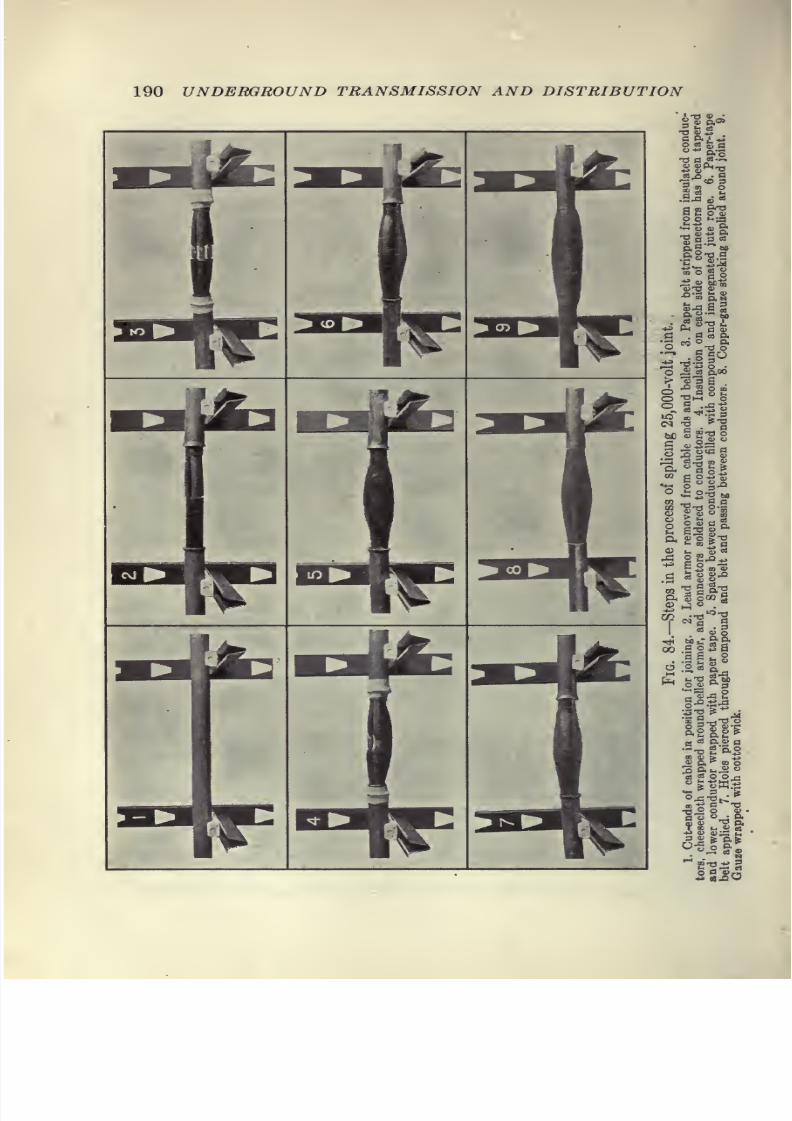
7/28/2019 Underground Trans 00 Me Yeu of t
http://slidepdf.com/reader/full/underground-trans-00-me-yeu-of-t 202/327
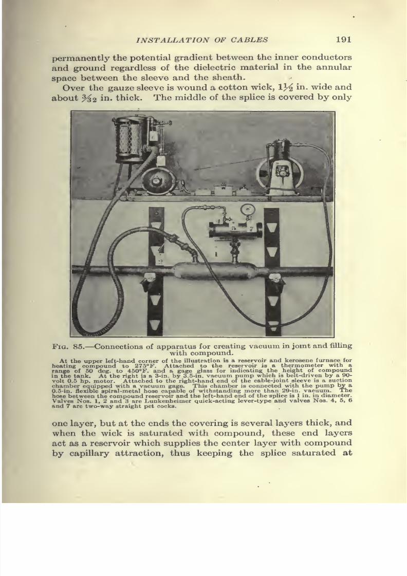
7/28/2019 Underground Trans 00 Me Yeu of t
http://slidepdf.com/reader/full/underground-trans-00-me-yeu-of-t 203/327
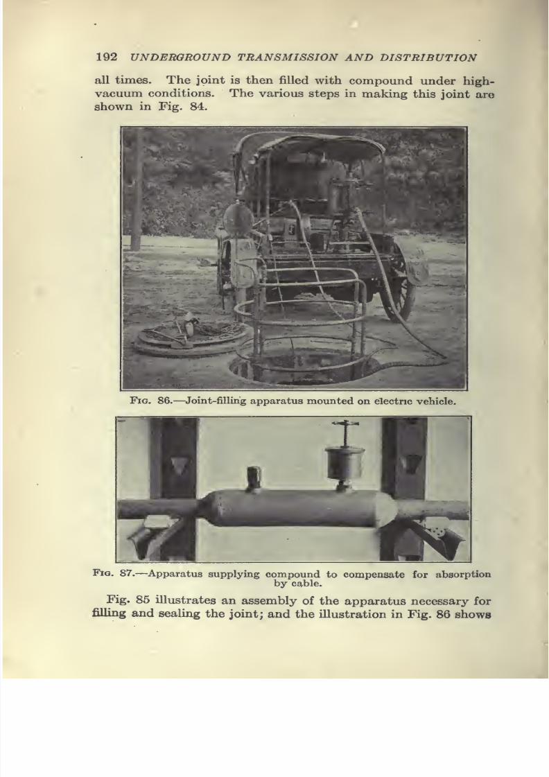
7/28/2019 Underground Trans 00 Me Yeu of t
http://slidepdf.com/reader/full/underground-trans-00-me-yeu-of-t 204/327
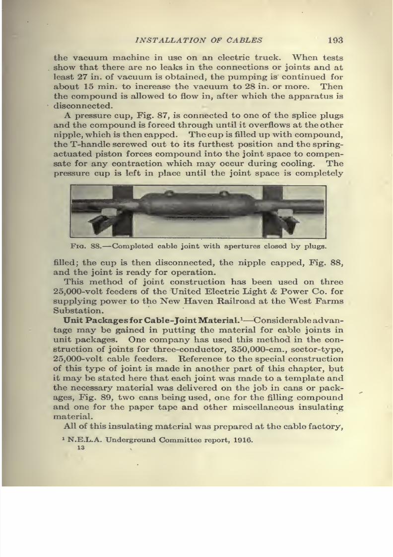
7/28/2019 Underground Trans 00 Me Yeu of t
http://slidepdf.com/reader/full/underground-trans-00-me-yeu-of-t 205/327
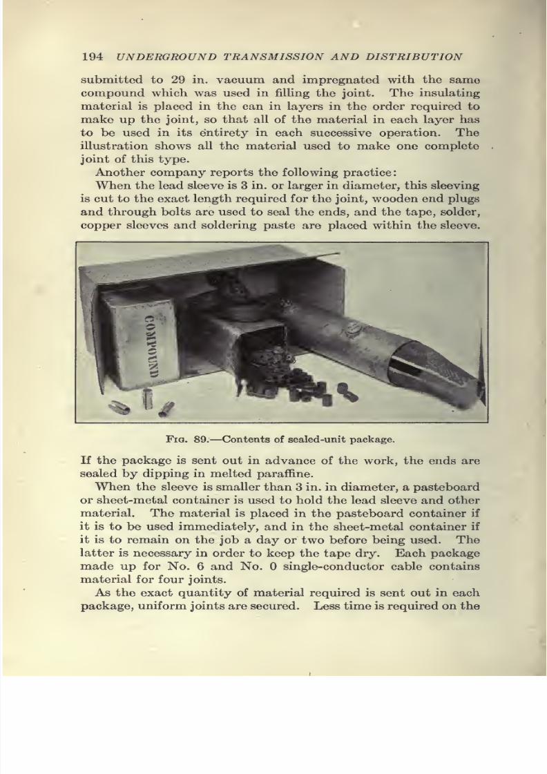
7/28/2019 Underground Trans 00 Me Yeu of t
http://slidepdf.com/reader/full/underground-trans-00-me-yeu-of-t 206/327
194 UNDERGROUND TRANSMISSION AND DISTRIBUTION
submitted to 29 in. vacuum and impregnated with the same
compound which was used in filHng the joint. The insulating
material is placed in the can in layers in the order required to
make up the joint, so that all of the material in each layer has
to be used in its entirety in each successive operation. The
illustration shows all the material used to make one complete
joint of this type.
Another company reports the following practice:
When the lead sleeve is 3 in. or larger in diameter, this sleeving
is cut to the exact length required for the joint, wooden end plugs
and through bolts are used to seal the ends, and the tape, solder,copper sleeves and soldering paste are placed within the sleeve.
1
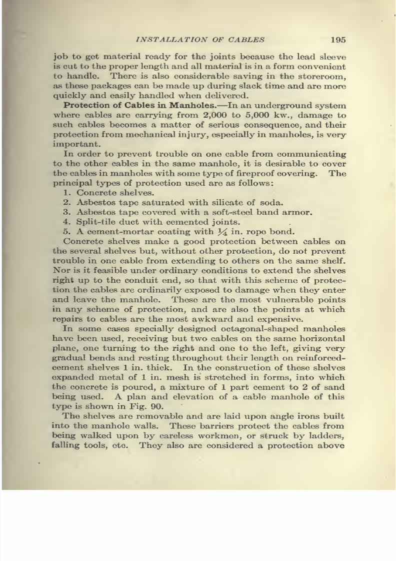
7/28/2019 Underground Trans 00 Me Yeu of t
http://slidepdf.com/reader/full/underground-trans-00-me-yeu-of-t 207/327
INSTALLATION OF CABLES 195
job to get material ready for the joints because the lead sleeve
is cut to the proper length and all material is in a form convenient
to handle. There is also considerable saving in the storeroom,as these packages can be made up during slack time and are more
quickly and easily handled when deUvered.
Protection of Cables in Manholes.—In an underground system
where cables are carrying from 2,000 to 5,000 kw., damage to
such cables becomes a matter of serious consequence, and their
protection from mechanical injury, especially in manholes, is very
important.
In order to prevent trouble on one cable from communicatingto the other cables in the same manhole, it is desirable to cover
the cables in manholes with some type of fireproof covering. The
principal types of protection used are as follows:
1. Concrete shelves.
2. Asbestos tape saturated with silicate of soda.
3. Asbestos tape covered with a soft-steel band armor.
4. Split-tile duct with cemented joints.
5. A cement-mortar coating with 34 iii- I'OP® bond.Concrete shelves make a good protection between cables on
the several shelves but, without other protection, do not prevent
trouble in one cable from extending to others on the same shelf.
Nor is it feasible under ordinary conditions to extend the shelves
right up to the conduit end, so that with this scheme of protec-
tion the cables are ordinarily exposed to damage when they enter
and leave the manhole. These are the most vulnerable points
in any scheme of protection,and
are alsothe
points atwhich
repairs to cables are the most awkward and expensive.
In some cases specially designed octagonal-shaped manholes
have been used, receiving but two cables on the same horizontal
plane, one turning to the right and one to the left, giving very
gradual bends and resting throughout their length on reinforced-
cement shelves 1 in. thick. In the construction of these shelves
expanded metal of 1 in. mesh is stretched in forms, into which
the concrete is poured, a mixture of 1 part cement to 2 of sand
being used. A plan and elevation of a cable manhole of this
type is shown in Fig. 90.
The shelves are removable and are laid upon angle irons built
into the manhole walls. These barriers protect the cables from
being walked upon by careless workmen, or struck by ladders,
falling tools, etc. They also are considered a protection above
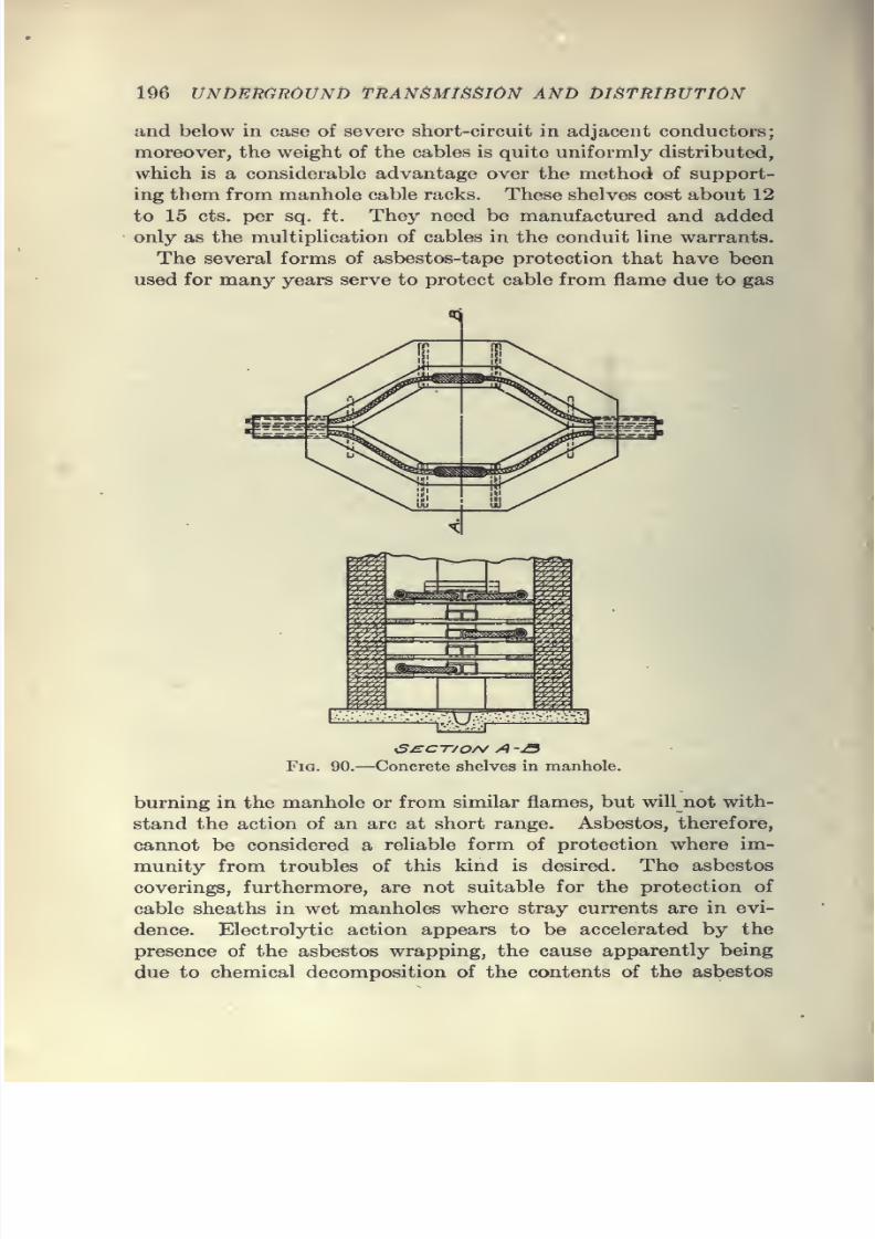
7/28/2019 Underground Trans 00 Me Yeu of t
http://slidepdf.com/reader/full/underground-trans-00-me-yeu-of-t 208/327
7/28/2019 Underground Trans 00 Me Yeu of t
http://slidepdf.com/reader/full/underground-trans-00-me-yeu-of-t 209/327
INSTALLATION OF CABLES 197
covering under conditions which promote rapid destruction of
cable sheaths.
SpUt tile laid on concrete or other types of shelves has been
used by a number of companies as a protective covering. Several
manufacturers make split tile in straight sections of regular length
as well as in short, straight lengths and with various degrees of
curvature. There still exists with this type of protection the
difficulty of applying the protection right up to the end of the
conduit ; and while it has been used in the past in large quantities,
its use has been abandoned in favor of the cement-mortar cover-
ing. Although tile is fireproof in the ordinary sense, it will melt
and flow in the case of a severe electric arc, and when this occurs,
the cable is exposed to the arc which melted the tile. The tile
is also injured by manhole explosions. It is difficult to cement
the joints properly so that there are, in general, a number of
weak points in the covering in each manhole. In addition, there
is considerable difficulty in a crowded manhole in tracing indi-
vidual cables after all have been covered with tile. The prices
demanded by the tile manufacturers for the split-tile duct in
straight pieces and in bends were of considerable influence in
the decision to abandon this type of covering.
The cement-mortar coating is not affected by manhole explo-
sions, and although the quality of the concrete and its strength
may be seriously affected by the arc, it will in general remain in
place and serve as a protection until it has been mechanically
removed. The companies that have tried this type of protection
are highly impressed with its value, and freely recommend its
adoption.
In determining the type of protection to be used, the heat-
resisting qualities of the covering are of more importance than
the heat-conducting quaHties. Even when covered with the
best non-conductor, the cables in the manholes will probably be
cooler than the cables in the conduit. The type of covering used,
therefore, has little, if any, influence on the carrying capacity
of the cables.
The cost of protecting cables by the several methods described
will, under ordinary circumstances, range between 20 and 30 cts.
per Un. ft. of cable.
Recent tests made to determine the relative value of two
types of protective covering for cables show very clearly the
marked superiority of cement mortar as compared with asbestos
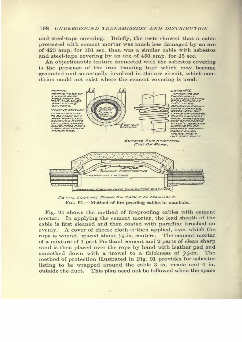
7/28/2019 Underground Trans 00 Me Yeu of t
http://slidepdf.com/reader/full/underground-trans-00-me-yeu-of-t 210/327
198 UNDERGROUND TRANSMISSION AND DISTRIBUTION
and steel-tape covering. Briefly, the tests showed that a cable
protected with cement mortar was much less damaged by an are
of 425 amp. for 101 sec. than was a similar cable -With, asbestos
and steel-tape covering by an arc of 450 amp. for 35 sec.
An objectionable feature connected with the asbestos covering
is the presence of the iron banding tape which may become
grounded and so actually involved in the arc circuit, which con-
dition could not exist where the cement covering is used.
mof/i»{i TOBe or
f^^ce /^/?oi^ oil-.
TAff Al^O AC/OBSfAC£D OA/^'ce^jTSf^a.
CCMCNT MlXTU/?£.
TO Be f^Aoe or, 1
fAITT p'OfTl.AHOccf^c/^T, s fA/rrsorct-CArj, SHAfrfSAf^^, r^etr r^of^t-OAM And OTHCfPIMPO^/T/eS.
A/?MO/f TO
0£THOfpOUGHL.yCU£AIV£0. COAT/I^orr^Ai^AnrsieATtio'c.ToaeB/PU3HCD £l/£/^l.YOV£rf? SU^A-AC£.cove/? W/TH oneLA Yc/r or CMeeaeci.orH i.AP/'eD t//\ICM. ArpiY secovoCOATorfA/PArineATiJso'CAsassrosl./3T/Hti TO Bey^^AffeD A/POUNDCABJ.e .3/A/CM
//\/S/oe /^n/o •*'
ours/oe j>c/ct.
Fig. 91.—Method of fire proofing cables in manhole.
Fig. 91 shows the method of fireproofing cables with cement
mortar. In applying the cement mortar, the lead sheath of the
cable is first cleaned and then coated with parafiine brushed on
evenly. A cover of cheese cloth is- then applied, over which the
rope is wound, spaced about J^-in. centers. The cement mortar
of a mixture of 1 part Portland cement and 2 parts of clean sharp
sand is then placed over the rope by hand with leather pad and
smoothed down with a trowel to a thickness of %-in. The
method of protection illustrated in Fig. 91 provides for asbestos
listing to be wrapped around the cable 3 in. inside and 4 in.
outside the duct. This plan need not be followed when the space
7/28/2019 Underground Trans 00 Me Yeu of t
http://slidepdf.com/reader/full/underground-trans-00-me-yeu-of-t 211/327
7/28/2019 Underground Trans 00 Me Yeu of t
http://slidepdf.com/reader/full/underground-trans-00-me-yeu-of-t 212/327
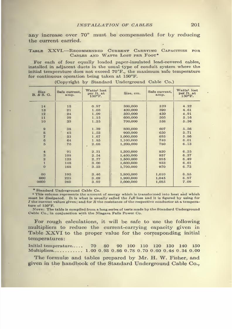
7/28/2019 Underground Trans 00 Me Yeu of t
http://slidepdf.com/reader/full/underground-trans-00-me-yeu-of-t 213/327
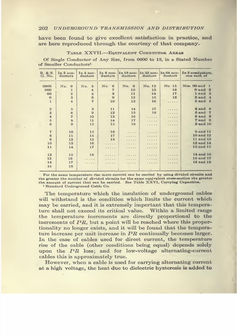
7/28/2019 Underground Trans 00 Me Yeu of t
http://slidepdf.com/reader/full/underground-trans-00-me-yeu-of-t 214/327
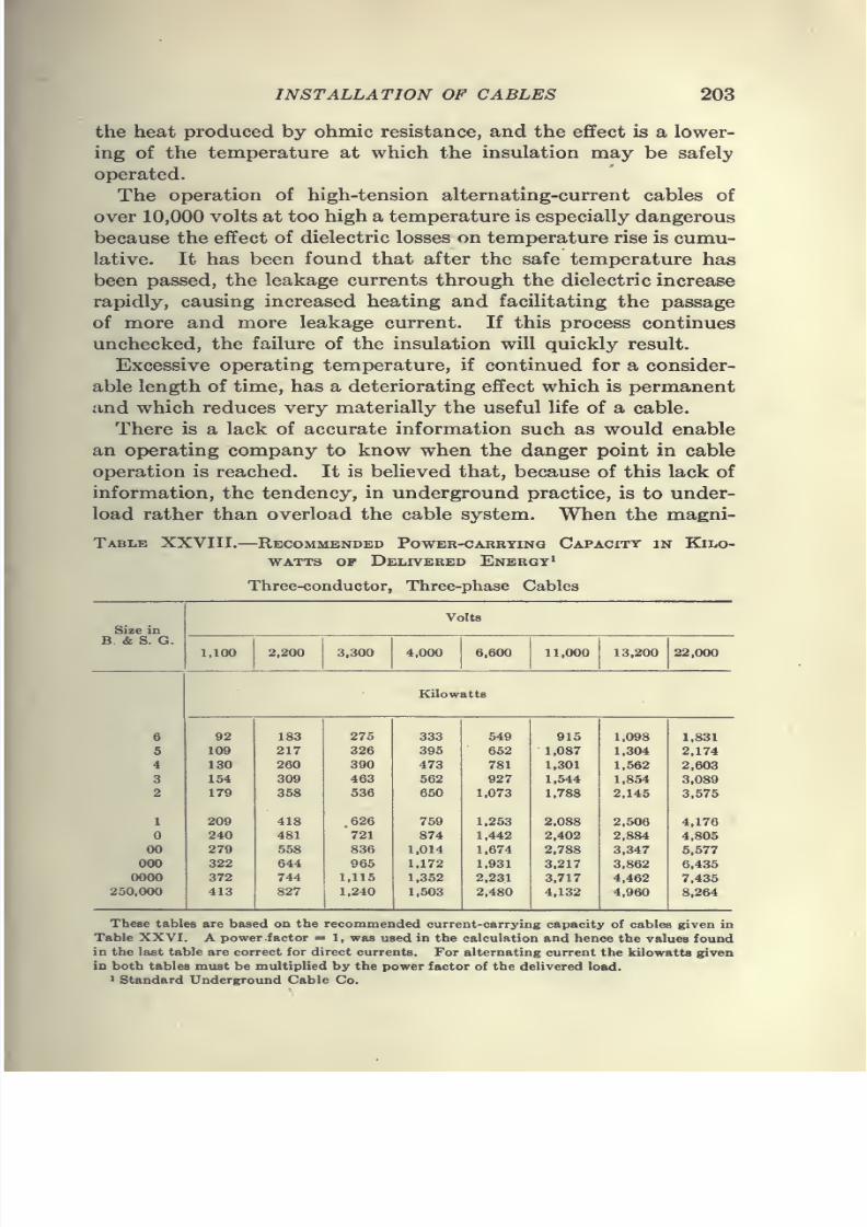
7/28/2019 Underground Trans 00 Me Yeu of t
http://slidepdf.com/reader/full/underground-trans-00-me-yeu-of-t 215/327
INSTALLATION OF CABLES 203
the heat produced by ohmic resistance, and the effect is a lower-
ing of the temperature at which the insulation may be safely
operated.
The operation of high-tension alternating-current cables of
over 10,000 volts at too high a temperature is especially dangerous
because the effect of dielectric losses on temperature rise is cumu-
lative. It has been found that after the safe temperature has
been passed, the leakage currents through the dielectric increase
rapidly, causing increased heating and facilitating the passage
of more and more leakage current. If this process continues
unchecked, the failure of the insulation will quickly result.
Excessive operating temperature, if continued for a consider-
able length of time, has a deteriorating effect which is permanent
and which reduces very materially the useful life of a cable.
There is a lack of accurate information such as would enable
an operating company to know when the danger point in cable
operation is reached. It is believed that, because of this lack of
information, the tendency, in underground practice, is to under-
load rather than overload the cable system. When the magni-
Table XXVIII. Recommended Power-carrying Capacity in Kilo-
watts OP Delivered Energy'
Three-conductor, Three-phase Cables
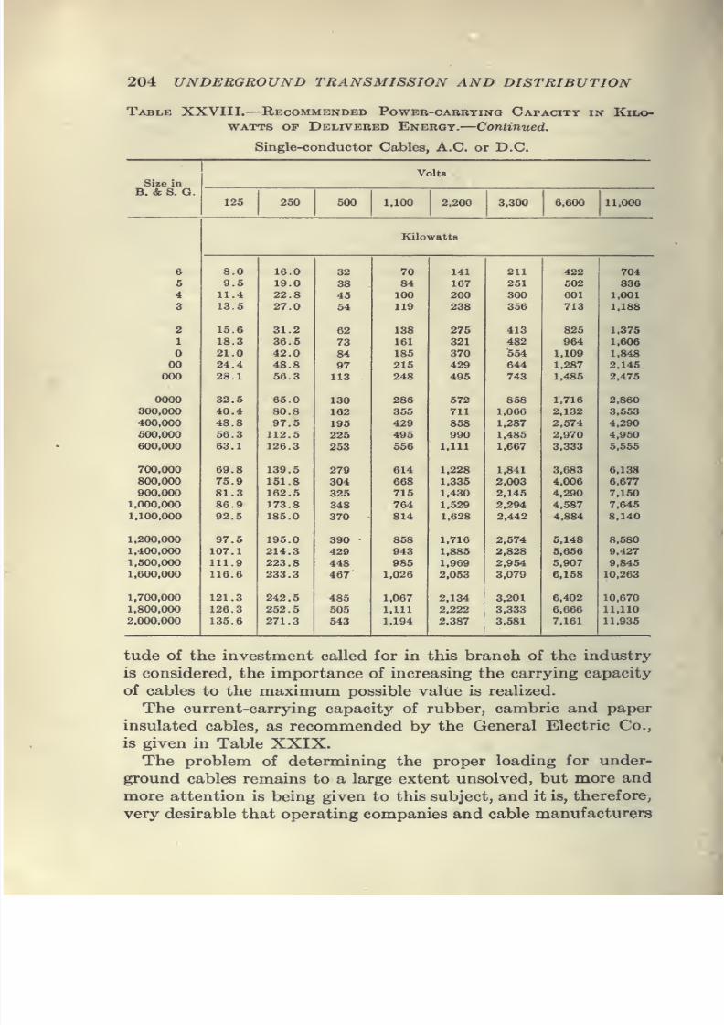
7/28/2019 Underground Trans 00 Me Yeu of t
http://slidepdf.com/reader/full/underground-trans-00-me-yeu-of-t 216/327
204 UNDERGROUND TRANSMISSION AND DISTRIBUTION
Tablk XXVIII. Recommended Power-carbying Capacity in Kilo-
watts OF Delivered Energy.—Continued.
Single-conductor Cables, A.C. or D.C.
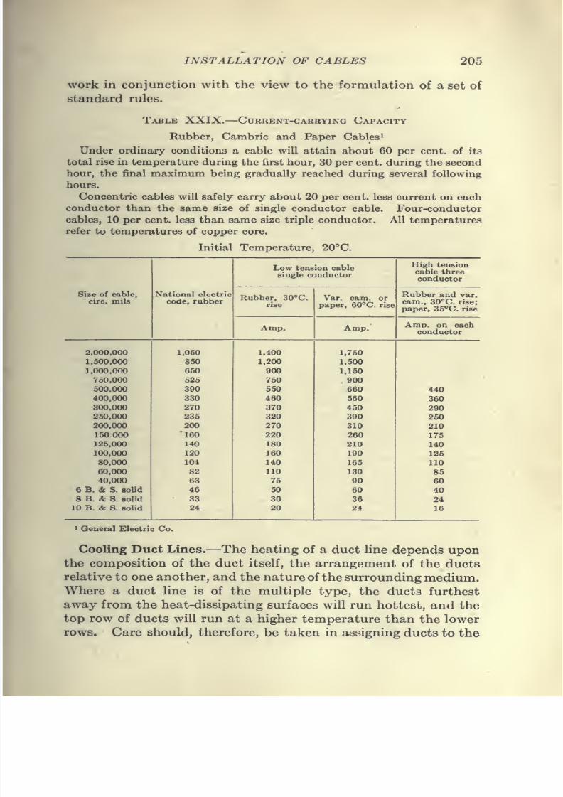
7/28/2019 Underground Trans 00 Me Yeu of t
http://slidepdf.com/reader/full/underground-trans-00-me-yeu-of-t 217/327
7/28/2019 Underground Trans 00 Me Yeu of t
http://slidepdf.com/reader/full/underground-trans-00-me-yeu-of-t 218/327
206 UNDERGROUND TRANSMISSION AND DISTRIBUTION
various cables that those cables which are expected to carry the
heaviest load be placed in the ducts which can best dispose of
the heat generated.
The nature of the surrounding medium is of importance in
determining the temperature of a duct line. It is a well-known
fact that the temperature of a duct of any given construction
will vary with changes in the character of the soil through which
it runs. Thus a line may give no trouble from overheating where
it runs through moist soil but is very likely to overheat in sections
where the soil is dry or sandy. Attempts have been made to
produce artificially the conditions favorable to rapid heat
dissipation, and various methods of cooling overheated duct
lines have been proposed, but as yet none has shown results which
would justify general adoption. A method of cooling by the
use of a porous-tile drain laid in a trench above the conduit
line was described in detail by Mr. L. E. Imlay in a paper pre-
sented before the American Institute of Electrical Engineers in
February, 1915. It was shown that the soil surrounding a buried
conduit containing active electric cables may become hot, dry
and powdery, a condition which would reduce its thermal con-
ductivity to a minimum. The addition of moisture to the soil,
either from above or from below through a vacant duct, brought
about a very distinct reduction in the temperature of the cables
as well as in the temperature of the surrounding soil. It seems
readily possible that future installations of heavily loaded con-
ducting cables, buried in conduits, will have special water-cooling
ducts laid in their immediate vicinity for the purpose of keepingdown the cable temperatures. A noteworthy point brought out
by the observations of the author is the relatively great distances
to which the heat liberated from active cables in the buried con-
duit can appreciably raise the temperature of the ground. It
appears that the temperature of the soil 1 meter below the surface
was raised by some 20^0 . at a distance of half a dozen meters
from the buried conduit.
The method employed by the Niagara Falls Power Co. forcooling its underground cables was to circulate water through
one of the vacant ducts adjacent to the occupied ducts. Later
porous drain tiles were installed parallel to and above the cable
ducts so that water flowing through the tile could percolate
through the ground surrounding the cable and finally be carried
away through agricultural tile drains installed below the ducts.
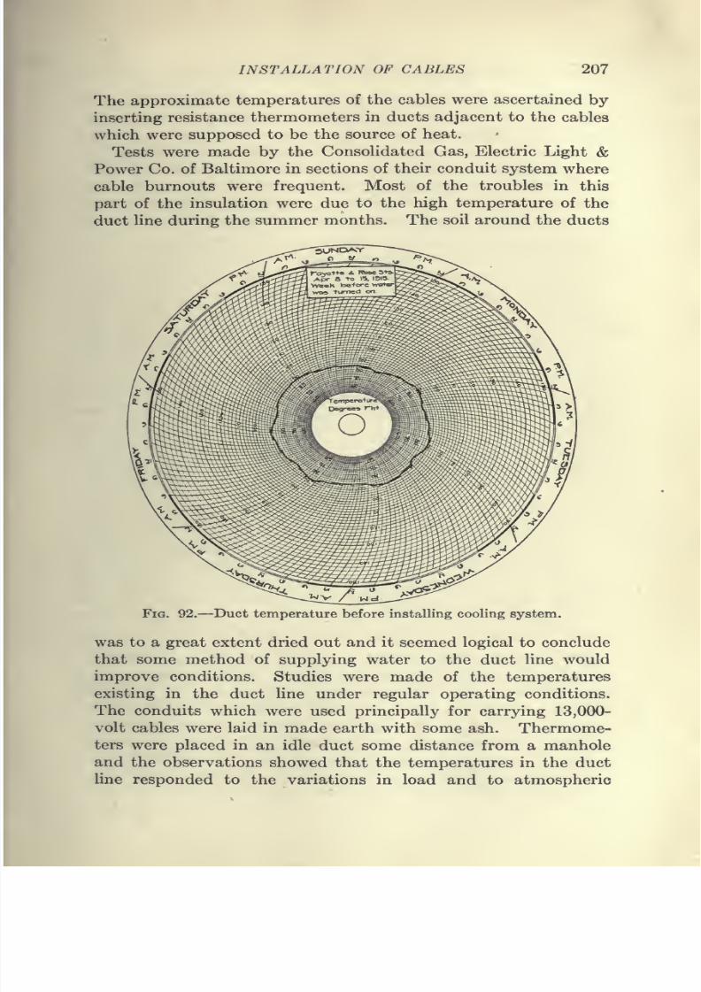
7/28/2019 Underground Trans 00 Me Yeu of t
http://slidepdf.com/reader/full/underground-trans-00-me-yeu-of-t 219/327
INSTALLATION OF CABLES 207
The approximate temperatures of the cables were ascertained by
inserting resistance thermometers in ducts adjacent to the cables
which were supposed to be the source of heat.
Tests were made by the Consolidated Gas, Electric Light &Power Co. of Baltimore in sections of their conduit system where
cable burnouts were frequent. Most of the troubles in this
part of the insulation were due to the high temperature of the
duct line during the summer months. The soil around the ducts
Fig. 92.—Duct temperature before installing cooling system.
was to a great extent dried out and it seemed logical to conclude
that some method of supplying water to the duct line would
improve conditions. Studies were made of the temperatures
existing in the duct line under regular operating conditions.
The conduits which were used principally for carrying 13,000-
volt cables were laid in made earth with some ash. Thermome-
ters were placed in an idle duct some distance from a manhole
and the observations showed that the temperatures in the duct
line responded to the variations in load and to atmospheric
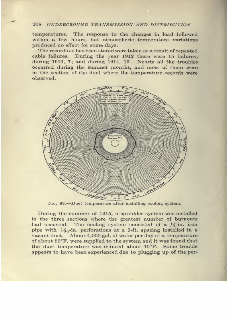
7/28/2019 Underground Trans 00 Me Yeu of t
http://slidepdf.com/reader/full/underground-trans-00-me-yeu-of-t 220/327
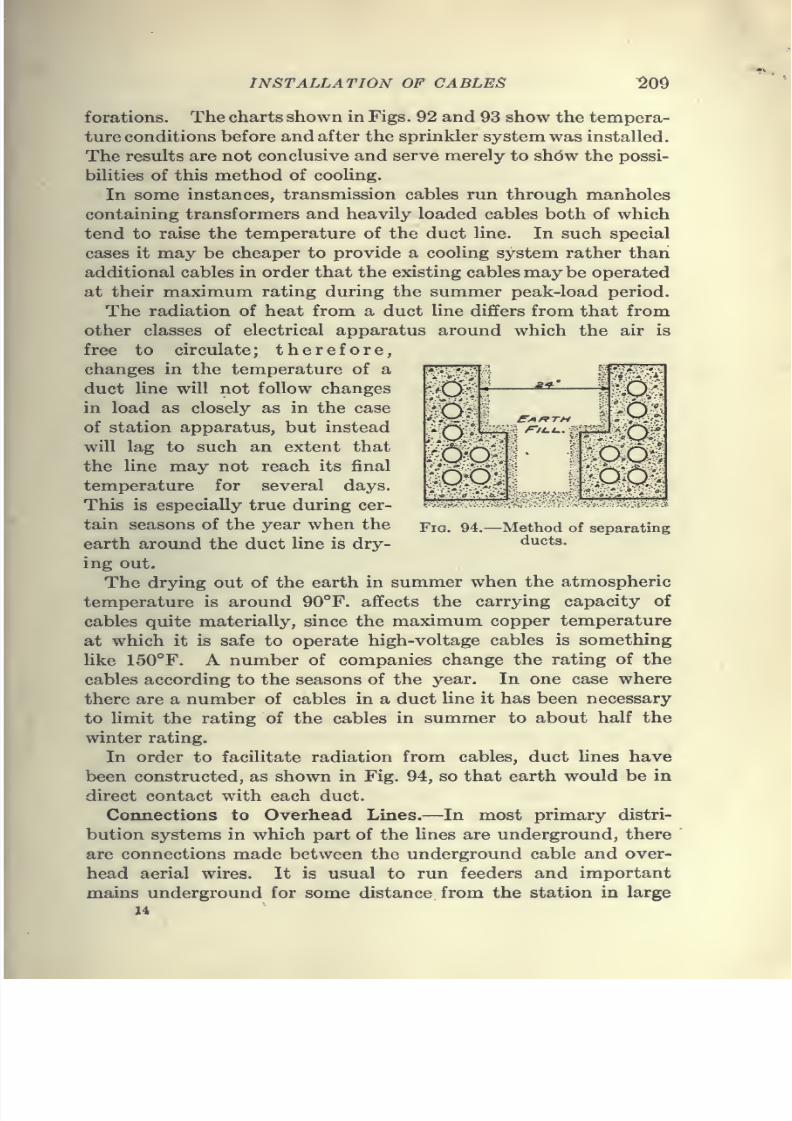
7/28/2019 Underground Trans 00 Me Yeu of t
http://slidepdf.com/reader/full/underground-trans-00-me-yeu-of-t 221/327
7/28/2019 Underground Trans 00 Me Yeu of t
http://slidepdf.com/reader/full/underground-trans-00-me-yeu-of-t 222/327
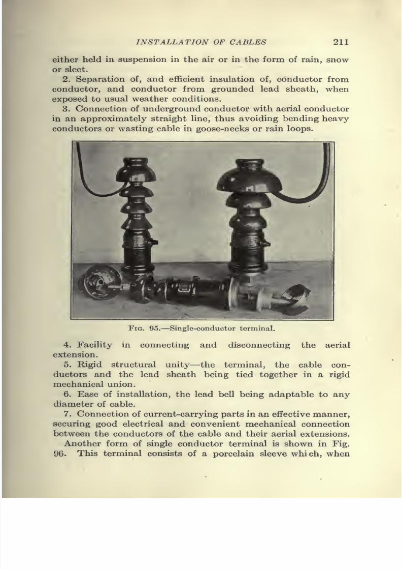
7/28/2019 Underground Trans 00 Me Yeu of t
http://slidepdf.com/reader/full/underground-trans-00-me-yeu-of-t 223/327
INSTALLATION OF CABLES 211
either held in suspension in the air or in the form of rain, snow
or sleet.
2. Separation of, and efficient insulation of, conductor from
conductor, and conductor from grounded lead sheath, when
exposed to usual weather conditions.
3. Connection of underground conductor with aerial conductor
in an approximately straight line, thus avoiding bending heavy-
conductors or wasting cable in goose-necks or rain loops.
Fig. 95.—Single-conductor terminal.
4. Facility in connecting and disconnecting the aerial
extension.
5. Rigid structural unity—the terminal, the cable con-
ductors and the lead sheath being tied together in a rigid
mechanical union.
6.
Easeof installation,
the leadbell
being adaptable to anydiameter of cable.
7. Connection of current-carrying parts in an effective manner,
securing good electrical and convenient mechanical connection
between the conductors of the cable and their aerial extensions.
Another form of single conductor terminal is shown in Fig.
96. This terminal consists of a porcelain sleeve which, when
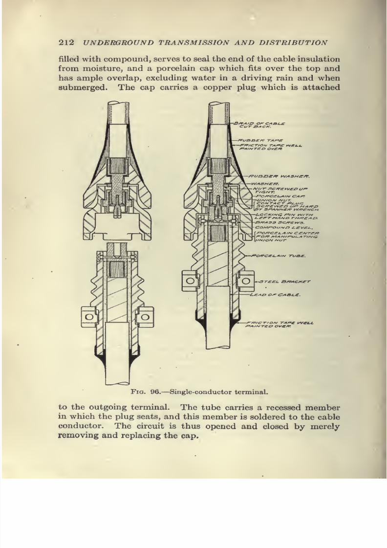
7/28/2019 Underground Trans 00 Me Yeu of t
http://slidepdf.com/reader/full/underground-trans-00-me-yeu-of-t 224/327
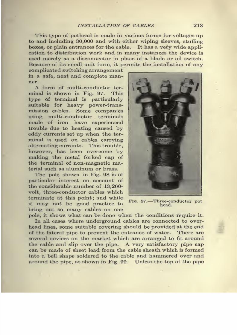
7/28/2019 Underground Trans 00 Me Yeu of t
http://slidepdf.com/reader/full/underground-trans-00-me-yeu-of-t 225/327
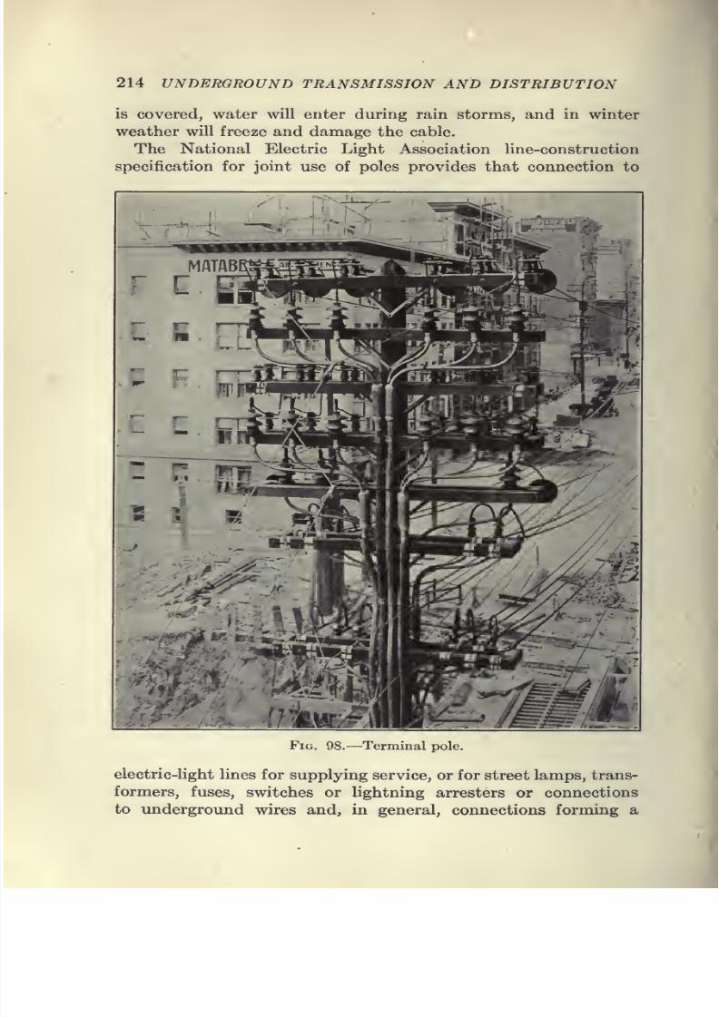
7/28/2019 Underground Trans 00 Me Yeu of t
http://slidepdf.com/reader/full/underground-trans-00-me-yeu-of-t 226/327
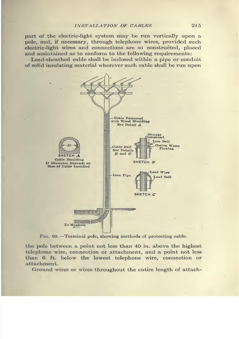
7/28/2019 Underground Trans 00 Me Yeu of t
http://slidepdf.com/reader/full/underground-trans-00-me-yeu-of-t 227/327
7/28/2019 Underground Trans 00 Me Yeu of t
http://slidepdf.com/reader/full/underground-trans-00-me-yeu-of-t 228/327
216 UNDERGROUND TRANSMISSION AND DISTRIBUTION
ment to the pole shall be inclosed within an insulating conduit,
or otherwise effectually insulated and protected. All cables,
wires, connections and conduits forming a part of the electric-
light system and carried vertically upon a pole within' the terms
of this article shall be placed upon the same circumference of the
pole on the crossarm side or face of the pole, it being further
provided that the poles jointly used and having such vertical
attachment shall be furnished with pole steps and that no vertical
attachment shall be so placed as to interfere with the use of pole
steps. Where vertical attachments of the lighting company pass
telephone crossarms, they shall be run behind the telephone cross-
arm and not across the face of such arms.
Lightning Arresters.—Where underground cables connect with
overhead wires, protection of cables against lightning is necessary;
and suitable arresters and fuses should be installed for this
purpose as well as to protect the station apparatus. Resonance
invariably produces high potentials at the junction of overhead
and underground lines, and these potentials are often of sufficient
value to break down the insulation of the cables and also the
insulation of apparatus installed on the system.
Whenever lines contain both inductance and capacity in ap-
preciable amounts, high voltages, which endanger the insulation
of the whole system and which it is impossible to detect on
ordinary switchboard instruments, may exist. Abnormal vol-
tages are, therefore, often found in circuits containing a com-
bination of underground and overhead circuits.
It is difficult, however, to determine the proper arresters for
such circuits on account of the various conditions to be met.
Where it is necessary to install hghtning arresters, the acces-
sibility, ease of inspection, voltage and power of the system, as
well as the length of underground and overhead lines, will be
important factors in the selection of a proper type. In all light-
ning-arrester installations it is of the utmost importance to make
proper ground connections, as many lightning-arrester troubles
can be traced to bad grounds.For grounding pole arresters, one or two 1-in. or 13^-in. iron
pipes should be driven into the ground at the base of the pole
and connected to the arrester by means of a copper wire not less
than No. 2. The ground wire should be protected for some
distance up the pole to prevent its being injured. The pipes
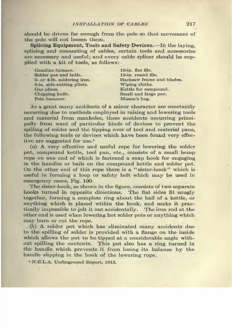
7/28/2019 Underground Trans 00 Me Yeu of t
http://slidepdf.com/reader/full/underground-trans-00-me-yeu-of-t 229/327
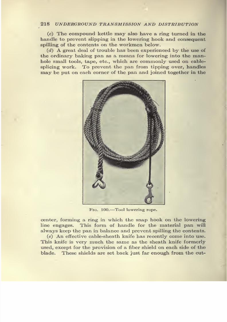
7/28/2019 Underground Trans 00 Me Yeu of t
http://slidepdf.com/reader/full/underground-trans-00-me-yeu-of-t 230/327
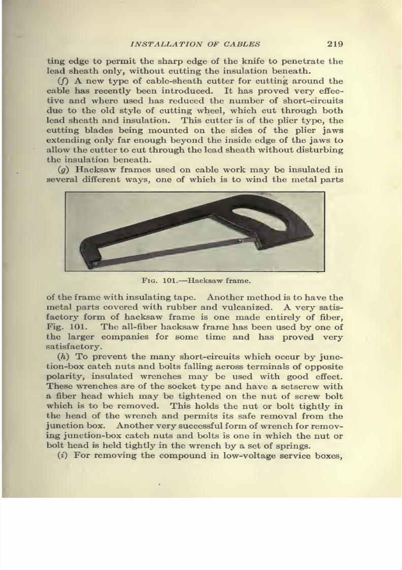
7/28/2019 Underground Trans 00 Me Yeu of t
http://slidepdf.com/reader/full/underground-trans-00-me-yeu-of-t 231/327
INSTALLATION OF CABLES 219
ting edge to permit the sharp edge of the knife to penetrate the
lead sheath only, without cutting the insulation beneath.
(J) A new type of cable-sheath cutter for cutting around the
cable has recently been introduced. It has proved very effec-
tive and where used has reduced the number of short-circuits
due to the old style of cutting wheel, which cut through both
lead sheath and insulation. This cutter is of the plier type, the
cutting blades being mounted on the sides of the plier jaws
extending only far enough beyond the inside edge of the jaws to
allow the cutter to cut through the lead sheath without disturbing
the insulation beneath.
(g) Hacksaw frames used on cable work may be insulated in
several different ways, one of which is to wind the metal parts
Fig. 101.—Hacksaw frame.
of the frame with insulating tape. Another method is to have the
metal parts covered with rubber and vulcanized. A very satis-
factory form of hacksaw frame is one made entirely of fiber,
Fig. 101. The all-fiber hacksaw frame has been used by one of
the larger companies for some time and has proved very
satisfactory.
(h) To prevent the many short-circuits which occur by junc-
tion-box catch nuts and bolts falling across terminals of opposite
polarity, insulated wrenches may be used with good effect.
These wrenches are of the socket type and have a setscrew with
a fiber head which may be tightened on the nut of screw bolt
which is to be removed. This holds the nut or bolt tightly in
the head of the wrench and permits its safe removal from the
junction box. Another very successful form of wrench for remov-
ing junction-box catch nuts and bolts is one in which the nut or
bolt head is held tightly in the wrench by a set of springs.
(i) For removing the compound in low-voltage service boxes,
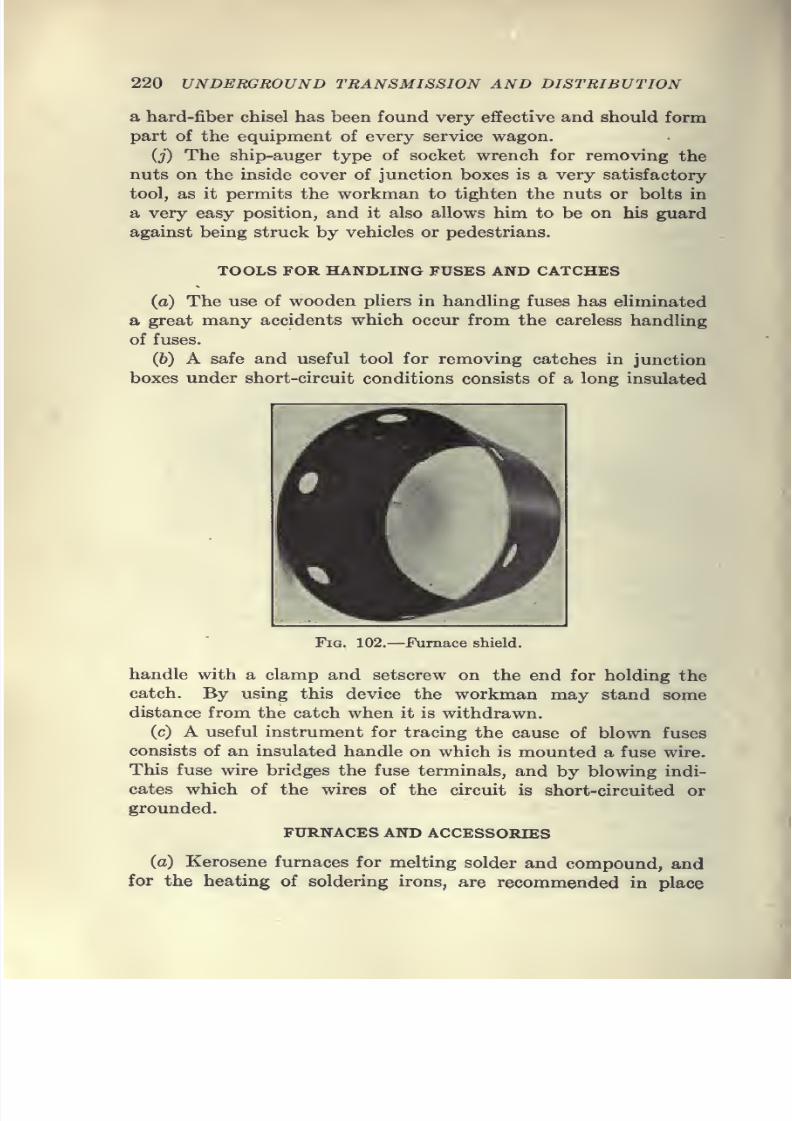
7/28/2019 Underground Trans 00 Me Yeu of t
http://slidepdf.com/reader/full/underground-trans-00-me-yeu-of-t 232/327

7/28/2019 Underground Trans 00 Me Yeu of t
http://slidepdf.com/reader/full/underground-trans-00-me-yeu-of-t 233/327
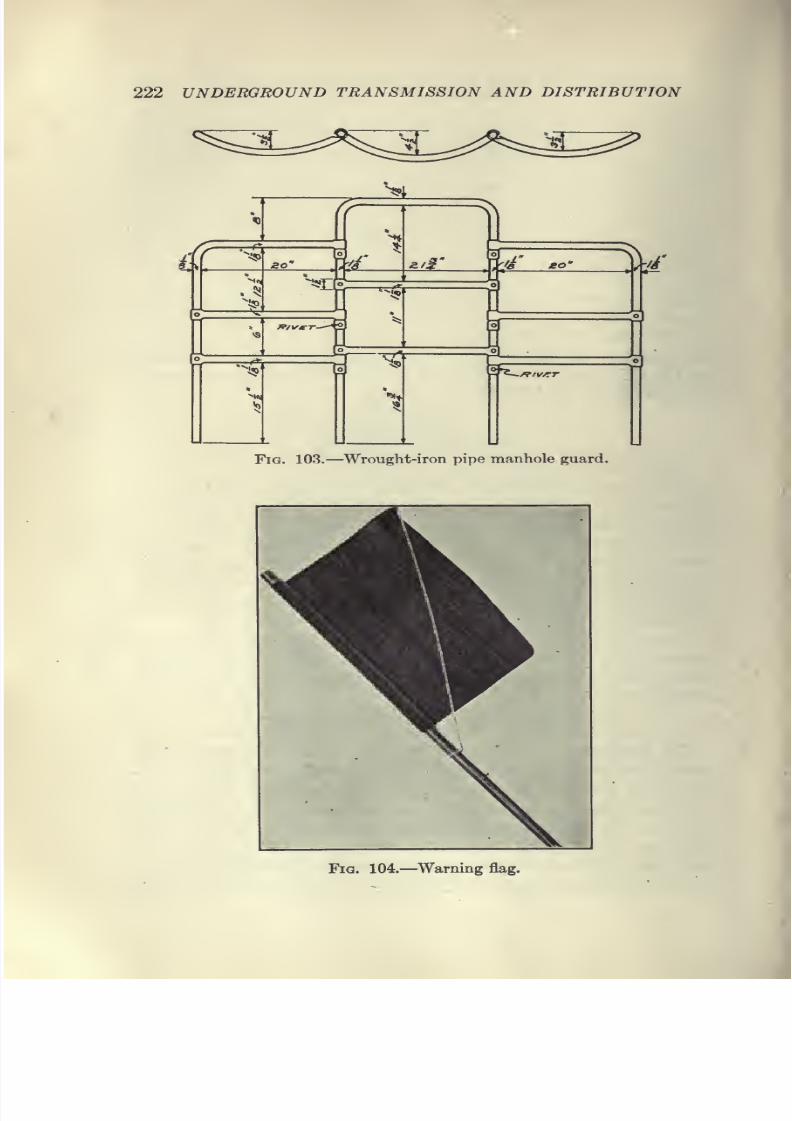
7/28/2019 Underground Trans 00 Me Yeu of t
http://slidepdf.com/reader/full/underground-trans-00-me-yeu-of-t 234/327
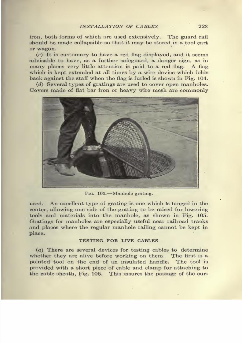
7/28/2019 Underground Trans 00 Me Yeu of t
http://slidepdf.com/reader/full/underground-trans-00-me-yeu-of-t 235/327

7/28/2019 Underground Trans 00 Me Yeu of t
http://slidepdf.com/reader/full/underground-trans-00-me-yeu-of-t 236/327
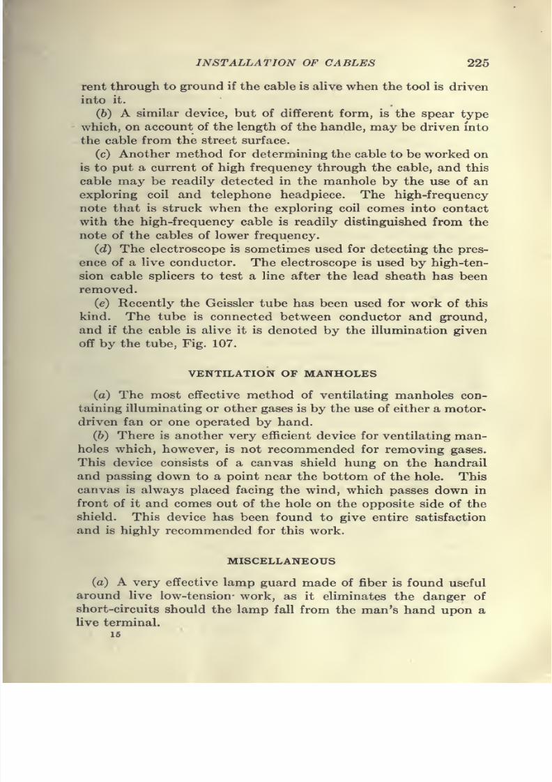
7/28/2019 Underground Trans 00 Me Yeu of t
http://slidepdf.com/reader/full/underground-trans-00-me-yeu-of-t 237/327
INSTALLATION OF CABLES 225
rent through to ground if the cable is alive when the tool is driven
into it.
(b) A similar device, but of different form, is the spear type
- which, on account of the length of the handle, may be driven into
the cable from the street surface.
(c) Another method for determining the cable to be worked on
is to put a current of high frequency through the cable, and this
cable may be readily detected in the manhole by the use of an
exploring coil and telephone headpiece. The high-frequency
note that is struck when the exploring coil comes into contact
with the high-frequency cable is readily distinguished from the
note of the cables of lower frequency.
(d) The electroscope is sometimes used for detecting the pres-
ence of a live conductor. The electroscope is used by high-ten-
sion cable splicers to test a line after the lead sheath has been
removed.
(e) Recently the Geissler tube has been used for work of this
kind. The tube is connected between conductor and ground,
and if the cable is alive it is denoted by the illumination given
off by the tube, Fig. 107.
VENTILATION OF MANHOLES
(a) The most effective method of ventilating manholes con-
taining illuminating or other gases is by the use of either a motor-
driven fan or one operated by hand.
(6) There is another very efficient device for ventilating man-holes which, however, is not recommended for removing gases.
This device consists of a canvas shield hung on the handrail
and passing down to a point near the bottom of the hole. This
canvas is always placed facing the wind, which passes down in
front of it and comes out of the hole on the opposite side of the
shield. This device has been found to give entire satisfaction
and is highly recommended for this work.
MISCELLANEOUS
(a) A very effective lamp guard made of fiber is found useful
around live low-tension- work, as it eliminates the danger of
short-circuits should the lamp fall from the man's hand upon a
live terminal.
15
7/28/2019 Underground Trans 00 Me Yeu of t
http://slidepdf.com/reader/full/underground-trans-00-me-yeu-of-t 238/327
7/28/2019 Underground Trans 00 Me Yeu of t
http://slidepdf.com/reader/full/underground-trans-00-me-yeu-of-t 239/327
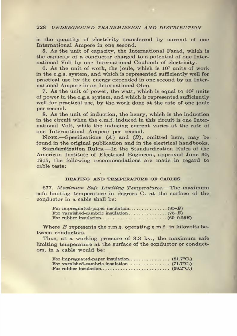
7/28/2019 Underground Trans 00 Me Yeu of t
http://slidepdf.com/reader/full/underground-trans-00-me-yeu-of-t 240/327
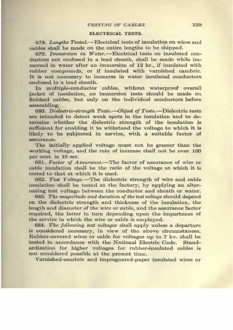
7/28/2019 Underground Trans 00 Me Yeu of t
http://slidepdf.com/reader/full/underground-trans-00-me-yeu-of-t 241/327
TESTING OF CABLES 229
ELECTRICAL TESTS.
678. Lengths Tested.—Electrical tests of insulation on wires and
cables shall be made on the entire lengths to be shipped.
679. Immersion in Water.—Electrical tests on insulated con-
ductors not enclosed in a lead sheath, shall be made while im-
mersed in water after an immersion of 12 hr., if insulated with
rubber compounds, or if insulated with varnished cambric.
It is not necessary to immerse in water insulated conductors
enclosed in a lead sheath.
In multiple-conductor cables, without waterproof overall
jacket of insulation, no immersion tests should be made on
finished cables, but only on the individual conductors before
assembling.
680. Dielectric-strength Tests.—Object of Tests.—Dielectric tests
are intended to detect weak spots in the insulation and to de-
termine whether the dielectric strength of the insulation is
sufficient for enabling it to withstand the voltage to which it is
likely to be subjected in service, with a suitable factor of
assurance.
The initially applied voltage must not be greater than the
working voltage, and the rate of increase shall not be over 100
per cent, in 10 sec.
QSl.. Factor of Assurance.—The factor of assurance of wire or
cable insulation shall be the ratio of the voltage at which it is
tested to that at which it is used.
682. Test Voltage.—The dielectric strength of wire and cable
insulation shall be tested at the factory, by applying an alter-
nating test voltage between the conductor and sheath or water.
683. The magnitude and duration of the test voltage should depend
on the dielectric strength and thickness of the insulation, the
length and diameter of the wire or cable, and the assurance factor
required, the latter in turn depending upon the importance of
the service in which the wire or cable is employed.
684. The following test voltages shall apply unless a departure
is considered necessary, in view of the above circumstances.
Rubber-covered wires or cable for voltages up to 7 kv. shall be
tested in accordance with the National Electric Code. Stand-
ardization for higher voltages for rubber-insulated cables is
not considered possible at the present time.
Varnished-cambric and impregnated-paper insulated wires or
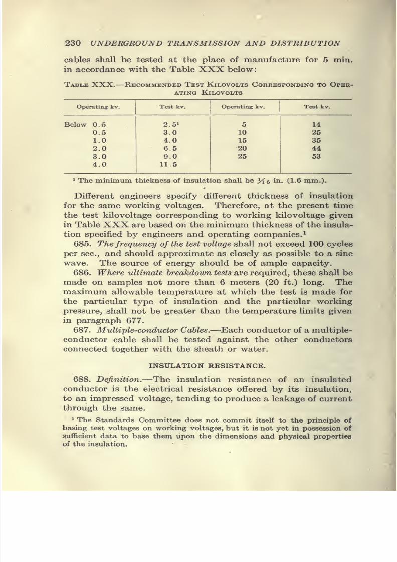
7/28/2019 Underground Trans 00 Me Yeu of t
http://slidepdf.com/reader/full/underground-trans-00-me-yeu-of-t 242/327
230 UNDERGROUND TRANSMISSION AND DISTRIBUTION
cables shall be tested at the place of manufacture for 5 min.
in accordance with the Table XXX below
Table XXX. Recommended Test Kilovolts Cokresponding to Oper-
ating KiLOVOLTS
Operating kv.
7/28/2019 Underground Trans 00 Me Yeu of t
http://slidepdf.com/reader/full/underground-trans-00-me-yeu-of-t 243/327
7/28/2019 Underground Trans 00 Me Yeu of t
http://slidepdf.com/reader/full/underground-trans-00-me-yeu-of-t 244/327
7/28/2019 Underground Trans 00 Me Yeu of t
http://slidepdf.com/reader/full/underground-trans-00-me-yeu-of-t 245/327
TESTING OF CABLES 233
Size = Watts = I X E
2irfCE _ 2TfCE^
1,000,000^
1,000,000
This means that the watts are proportional to the frequency
capacity and the square of the voltage, and on high-voltage tests
this means large apparatus. For instance, 1,000 ft. of a 500,000-
cm. cable with ^^2-in. wall of 30 per cent. Para has a capacity of
about 0.33 microfarads. With a frequency of 25 cycles, this for-
mula shows that 1.3 kw. capacity is required to test at 5,000 volts.
If this cable were to be tested at 30,000 volts, apparatus 36 times
as large, or of about 47 kw., would be required. If 60 cycles
instead of 25 were used, a 30,000-volt test would mean that the
apparatus would have to have a capacity of about 113 kw.
According to the best information available, there appears to
be no appreciable difference in severity between testing at 25 or
60 cycles on ordinary factory tests.
Locating and Repairing Cable Failures.—Numerous methods
have been tried for locating faults in underground transmission
cables, some companies depending upon the use of an intermittent
current on the damaged cable, which is then explored bymeans
of an induction coil and telephone receiver, while other companies
make use of the Murray loop test. Most companies avail them-
selves more or less of the method of inspection when locating
faults by sending men over the route of the cable.
As stated by W. A. Durgin, in a paper presented before the
National Electric Light Association in 1910, fault location in
high-tension power cables requires quite a different procedure
from that usually outlined in texts upon cable testing, due to the
wide difference in the characteristics of construction between
power and intelligence transmissions. The " cut-and-try
method is applicable to both, but if a quicker and less expensive
system is desired testing equipment of special design must be
provided.
Most of the larger companies have provided themselves with
a testing transformer which is used in connection with a motor-
driven generator to supply current of varying voltage for the
purpose of breaking down a faulty cable or applying a high-
tension test. For the purpose of expediting, as much as possible,
the work of locating and repairing a cable fault, specific rules
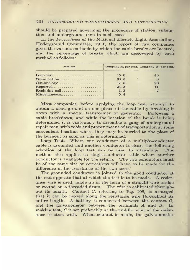
7/28/2019 Underground Trans 00 Me Yeu of t
http://slidepdf.com/reader/full/underground-trans-00-me-yeu-of-t 246/327
234 UNDERGROUND TRANSMISSION AND DISTRIBUTION
should be prepared governing the procedure of station, substa-
tion and underground men in such cases.
In the Proceedings of the National Electric Light Association,
Underground Committee, 1911, the report of two companies
gives the various methods by which the cable breaks are located,
and the percentage of breaks which are discovered by each
method as follows:
Method Company B, per cent.
Loop test. . . .
Examination
.
Cut-and-try .
.
Reported
Exploring coil
Miscellaneous
46
8
28
11
7
Most companies, before applying the loop test, attempt to
obtain a dead ground on one phase of the cable by breaking it
down with a special transformer or generator. Following a
cable breakdown, and while the location of the break is being
determined it is customary to assemble a gang of underground
repair men, with tools and proper means of transportation at some
convenient location where they may be hurried to the place of
the burnout as soon as this is determined.
Loop Test.—Where one conductor of a multiple-conductor
cable is grounded and another conductor is clear, the following
adaption of the loop test can be used to advantage. Thismethod also applies to single-conductor cable where another
conductor is available for the return. The two conductors must
be of the same size or corrections will have to be made for the
difference in the resistance of the two sizes.
The grounded conductor is jointed to the good conductor at
the end opposite that at which the test is to be made. A resist-
ance wire is used, made up in the form of a straight wire bridge
or wound on a threaded drum. The wire is calibrated through-out its length. Contact C, referring to Fig. 108, is arranged
that it can be moved along the resistance wire throughout its
entire length. A battery is connected between the contact C,
and the galvanometer between the terminals A and B. In
making test, C is set preferably at the middle point of the resist-
ance to start with. When contact is made, the galvanometer
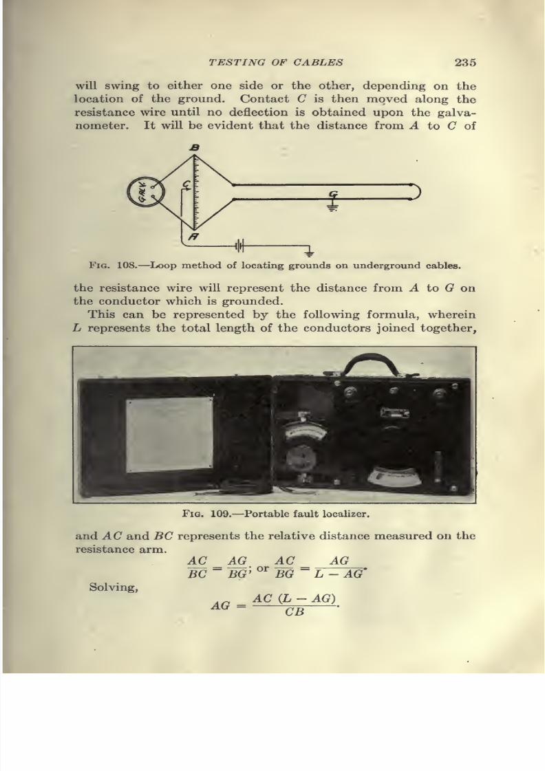
7/28/2019 Underground Trans 00 Me Yeu of t
http://slidepdf.com/reader/full/underground-trans-00-me-yeu-of-t 247/327
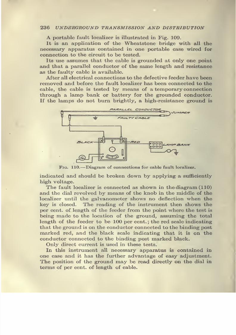
7/28/2019 Underground Trans 00 Me Yeu of t
http://slidepdf.com/reader/full/underground-trans-00-me-yeu-of-t 248/327
236 UNDERGROUND TRANSMISSION AND DISTRIBUTION
A portable fault localizer is illustrated in Fig. 109.
It is an application of the Wheatstone bridge with all the
necessary apparatus contained in one portable case wired for
connection to the circuit to be tested.
Its use assumes that the cable is grounded at only one point
and that a parallel conductor of the same length and resistance
as the faulty cable is available.
After all electrical connections to the defective feeder have been
removed and before the fault localizer has been connected to the
cable, the cable is tested by means of a temporary connection
through a lamp bank or battery for the grounded conductor.
If the lamps do not burn brightly, a high-resistance ground is
yCVl /rVt Z. /.£-^ COfV^POCTO/?l7UA/7^jr/j'
i-/iM/='eANK
Fig. 110.—Diagram of connections for cable fault localizer.
indicated and should be broken down by applying a sufficiently
high voltage.
The fault localizer is connected as shown in the diagram (110)
and the dial revolved by means of the knob in the middle of the
localizer until the galvanometer shows no deflection when the
key is closed. The reading of the instrument then shows the
per cent, of length of the feeder from the point where the test is
being made to the location of the ground, assuming the total
length of the feeder to be 100 per cent. ; the red scale indicating
that the ground is on the conductor connected to the binding post
marked red, and the black scale indicating that it is on the
conductor connected to the binding post marked black.
Only direct current is used in these tests.
In this instrument all necessary apparatus is contained in
one case and it has the further advantage of easy adjustment.
The position of the ground may be read directly on the dial in
terms of per cent, of length of cable.
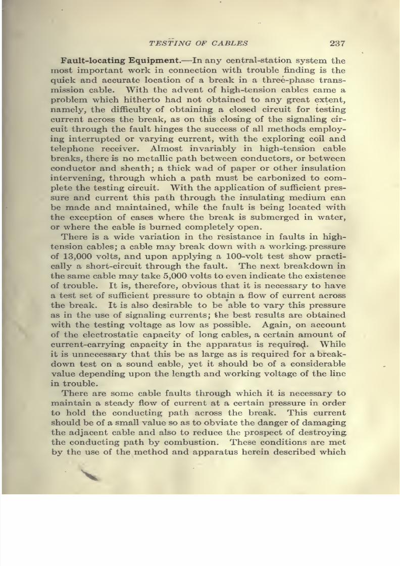
7/28/2019 Underground Trans 00 Me Yeu of t
http://slidepdf.com/reader/full/underground-trans-00-me-yeu-of-t 249/327
TESTING OF CABLES 237
Fault-locating Equipment.—In any central-station system the
most important work in connection with trouble finding is the
quick and accurate location of a break in a three-phase trans-
mission cable. With the advent of high-tension cables came a
problem which hitherto had not obtained to any great extent,
namely, the difl&culty of obtaining a closed circuit for testing
current across the break, as on this closing of the signaling cir-
cuit through the fault hinges the success of all methods employ-
ing interrupted or varying current, with the exploring coil and
telephone receiver. Almost invariably in high-tension cable
breaks, there is no metallic path between conductors, or between
conductor and sheath; a thick wad of paper or other insulation
intervening, through which a path must be carbonized to com-
plete the testing circuit. With the application of sufficient pres-
sure and current this path through the insulating medium can
be made and maintained, while the fault is being located with
the exception of cases where the break is submerged in water,
or where the cable is burned completely open.
There is a wide variation in the resistance in faults in high-
tension cables; a cable may break down with a working, pressure
of 13,000 volts, and upon applying a 100-volt test show practi-
cally a short-circuit through the fault. The next breakdown in
the same cable may take 5,000 volts to even indicate the existence
of trouble. It is, therefore, obvious that it is necessary to have
a test set of sufficient pressure to obtain a flow of current across
the break. It is also desirable to be able to vary this pressure
as in the use of signaling currents; the best results are obtained
with the testing voltage as low as possible. Again, on account
of the electrostatic capacity of long cables, a certain amount of
current-carrying capacity in the apparatus is require<^. While
it is unnecessary that this be as large as is required for a break-
down test on a sound cable, yet it should be of a considerable
value depending upon the length and working voltage of the line
in trouble.
There are some cable faults through which it is necessary to
maintain a steady flow of current at a certain pressure in order
to hold the conducting path across the break. This current
should be of a small value so as to obviate the danger of damaging
the adjacent cable and also to reduce the prospect of destroying
the conducting path by combustion. These conditions are met
by the use of the method and apparatus herein described which
7/28/2019 Underground Trans 00 Me Yeu of t
http://slidepdf.com/reader/full/underground-trans-00-me-yeu-of-t 250/327
7/28/2019 Underground Trans 00 Me Yeu of t
http://slidepdf.com/reader/full/underground-trans-00-me-yeu-of-t 251/327
TESTING OF CABLES 239
The apparatus is designed to be used by the ordinary trouble
hunter without the use of laboratory instruments, and it can be
used to advantage in conjunction with the power bridge loop
and capacity instruments, etc., to locate faults exactly without
opening any joints in cables.
The signaling system can be adapted to any existing type of
breakdown apparatus.
It is often desirable to be able to pick out the different legs or
phases of an alternating circuit, at some point distant from the
source of supply. This can be done by superposing the inter-
rupted currents on the primary line through an ordinary trans-
former without any interference in the working of the circuit.
By applying the exploring coils to the different wires of the cir-
cuit it can be determined to which pair the interrupter is con-
nected. Likewise, if it is desired to know which phase supplies
a certain customer, by attaching a plug to a lamp socket and
listening through a telephone receiver connected to a special
type of coil, this can be readily determined.
A diagnosis and a somewhat predictive location of faults canbe made with a little experience in working the apparatus.
Faults in water show certain characteristics and the wet holes
being known, some idea is given of the location of the breaks.
Experience in carbonizing a fault shows whether it is in a section
of cable or in a joint by measuring the charging current the
distance to an open end can be approximately figured. If there
is a cross between the live side of a grounded secondary and a
primary orstreet-lighting circuit,
this can be shown in advance.Advantage can be taken of the phenomenon of resonance to
discriminate between the natural leakage and charging current
of a circuit, and fault current, all of which makes it much easier
to locate trouble.
For secondary networks, and breaks in low resistance, on
isolated lines and cables, a portable vibrating interrupter, which
will operate on two dry cells, has been developed. This inter-
rupter gives a very good signal and can be heard through 1,000
ohms resistance. While the foregoing apparatus is intended
primarily for underground cables it can be used with the same
success on overhead lines.
The method and apparatus was devised by James A. Vahey, of
the Edison Electric Illuminating Co. of Boston, Mass.
7/28/2019 Underground Trans 00 Me Yeu of t
http://slidepdf.com/reader/full/underground-trans-00-me-yeu-of-t 252/327
7/28/2019 Underground Trans 00 Me Yeu of t
http://slidepdf.com/reader/full/underground-trans-00-me-yeu-of-t 253/327
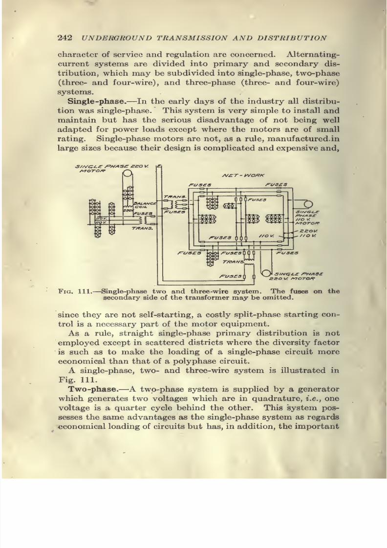
7/28/2019 Underground Trans 00 Me Yeu of t
http://slidepdf.com/reader/full/underground-trans-00-me-yeu-of-t 254/327
242 UNDERGROUND TRANSMISSION AND DISTRIBUTION
character of service and regulation are concerned. Alternating-
current systems are divided into primary and secondary dis-
tribution, which may be subdivided into single-phase, two-phase(three- and four-wire), and three-phase (three- and four-wire)
systems.
Single-phase.—In the early days of the industry all distribu-
tion was single-phase. This system is very simple to install and
maintain but has the serious disadvantage of not being well
adapted for power loads except where the motors are of small
rating. Single-phase motors are not, as a rule, manufactured in
large sizes because their design is complicated and expensive and,
Af£:r-i/\/o/9K
1 1 \J^ siNc;t.£ ^HAsesso vr f^oTO/^
Fig. 111.—Single-phase two and three-wire system. The fuses on the
secondary side of the transformer may be omitted.
since they are not self-starting, a costly split-phase starting con-
trol is a necessary part of the motor equipment.
As a rule, straight single-phase primary distribution is not
employed except in scattered districts where the diversity factor
is such as to make the loading of a single-phase circuit more
economical than that of a polyphase circuit.
A single-phase, two- and three-wire system is illustrated in
Fig. 111.Two-phase.—A two-phase system is supplied by a generator
which generates two voltages which are in quadrature, i.e., one
voltage is a quarter cycle behind the other. This system pos-
sesses the same advantages as the single-phase system as regards
economical loading of circuits but has, in addition, the important
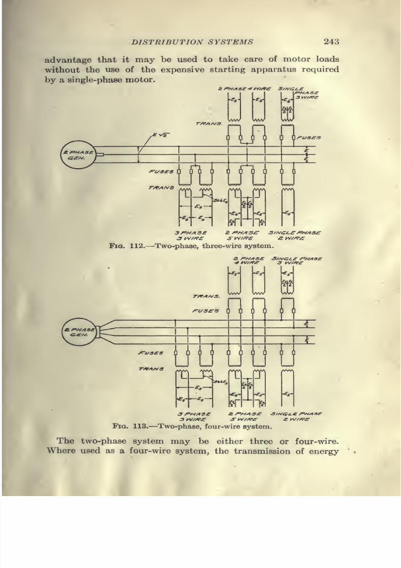
7/28/2019 Underground Trans 00 Me Yeu of t
http://slidepdf.com/reader/full/underground-trans-00-me-yeu-of-t 255/327
DISTRIBUTION SYSTEMS 243
advantage that it may be used to take care of motor loads
without the use of the expensive starting apparatus required
by a single-phase motor.
3PHAS£
3 yv//?£
2 fi'HASC S//^e;/.£/^fMS^
Fia. 112.—Two-phase, three-wire system.
Z fH^ae •S//ve;i.£ f'UAse* tv//f£- 3 yv/^£
/vwv
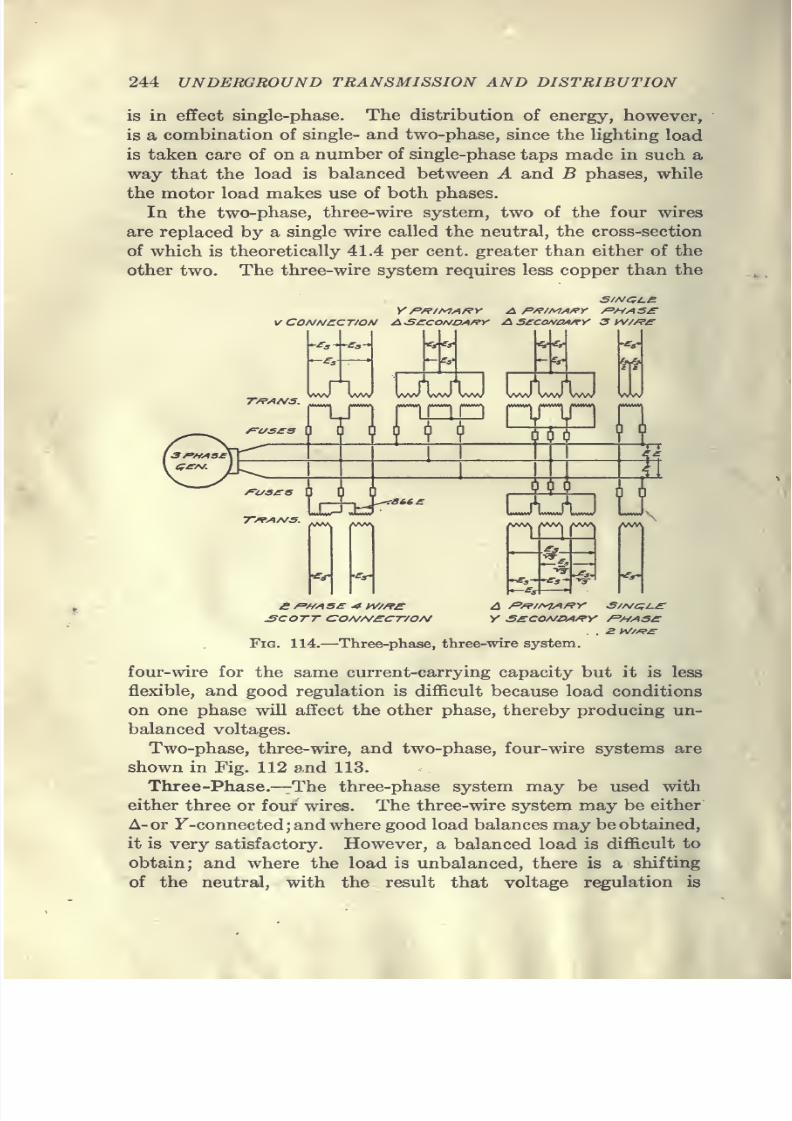
7/28/2019 Underground Trans 00 Me Yeu of t
http://slidepdf.com/reader/full/underground-trans-00-me-yeu-of-t 256/327
244 UNDERGROUND TRANSMISSION AND DISTRIBUTION
is in effect single-phase. The distribution of energy, however,
is a combination of single- and two-phase, since the lighting load
is taken care of on a number of single-phase taps made in such a
way that the load is balanced between A and B phases, while
the motor load makes use of both phases.
In the two-phase, three-wire system, two of the four wires
are replaced by a single wire called the neutral, the cross-section
of which is theoretically 41.4 per cent, greater than either of the
other two. The three-wire system requires less copper than the
V CONNECTION AS£:cONDA/9y A SSCO/VO/l/^r 3 y^//?£
-<»--^a-
T/?AA/S.^vW WW WW WW WW VVW WW WW
9 V til)
6y&
WW
n
\A:dr''''
OOP
^rf- '^S'
wvv VV/V\ AAA/>
M•.^^-7^^^
u
<f
£COTT CO/\//\/£CT/0/\/ Y S£CONDA/?Y /='HASC
Fig. 114.—Three-phase, three-wire system.
four-wire for the same current-carrying capacity but it is less
flexible, and good regulation is difficult because load conditions
on one phase will affect the other phase, thereby producing un-
balanced voltages.
Two-phase, three-wire, and two-phase, four-wire systems are
shown in Fig. 112 and 113.
Three-Phase.—The three-phase system may be used with
either three or four wires. The three-wire system may be either
A- or F-connected ; and where good load balances may be obtained,
it is very satisfactory. However, a balanced load is difficult to
obtain; and where the load is unbalanced, there is a shifting
of the neutral, with the result that voltage regulation is
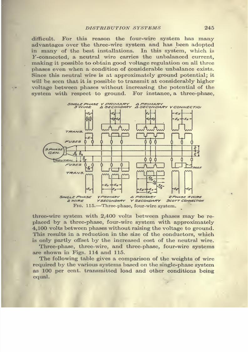
7/28/2019 Underground Trans 00 Me Yeu of t
http://slidepdf.com/reader/full/underground-trans-00-me-yeu-of-t 257/327
DISTRIBUTION SYSTEMS 245
difl&cult. For this reason the four-wire system has many
advantages over the three-wire system and has been adopted
in many of the best installations. In this system, which is
F-connected, a neutral wire carries the unbalanced current,
making it possible to obtain good voltage regulation on all three
phases even when a condition of considerable unbalance exists.
Since this neutral wire is at approximately ground potential; it
will be seen that it is possible to transmit at considerably higher
voltage between phases without increasing the potential of the
system with respect to ground. For instance, a three-phase,
3 W/^£ A S£COf^VAf?Y AS£COA/OA/?Y V CONNeCT/Of
'Ci'^i •Ci-Ci
VWV VWV Ww VVW WW vvw
y.A
\J^ \\
L-rt_AJ
VW\ jVW\ VVV>j
-^-r,-
WVV (VWV VWV
StN^L£ PHASSZ iV//?£
YPfTfMA/rY
YsecoNOAKY V SCCONOAfifYBPMASe ^W//f£Scott CONN£cr/oN
Fig. 115.—Three-phase, four-wire system.
three-wire system with 2,400 volts between phases may be re-
placed by a three-phase, four-wire system with approximately
4,100 volts between phases without raising the voltage to ground.
This results in a reduction in the size of the conductors, which
is only partly offset by the increased cost of the neutral wire.
Three-phase, three-wire, and three-phase, four-wire systems
are shown in Figs. 114 and 115.
The following table gives a comparison of the weights of wire
required by the various systems based on the single-phase system
as 100 per cent, transmitted load and other conditions being
equal.
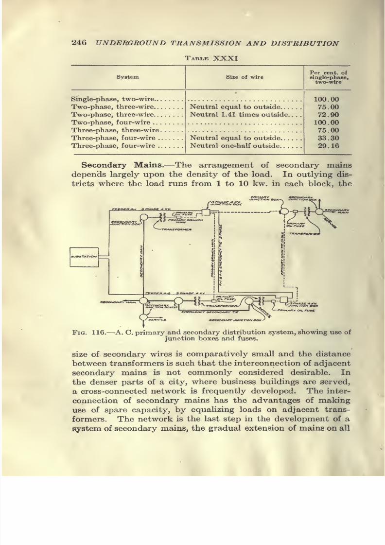
7/28/2019 Underground Trans 00 Me Yeu of t
http://slidepdf.com/reader/full/underground-trans-00-me-yeu-of-t 258/327
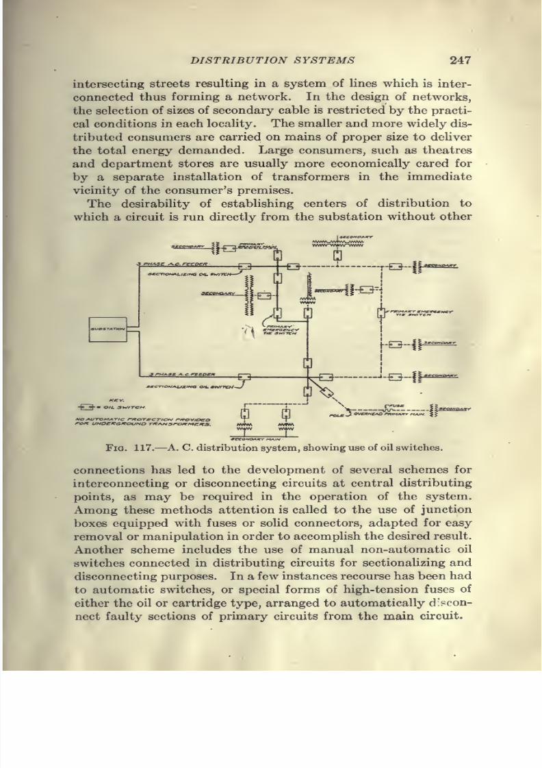
7/28/2019 Underground Trans 00 Me Yeu of t
http://slidepdf.com/reader/full/underground-trans-00-me-yeu-of-t 259/327
DISTRIBUTION SYSTEMS 247
intersecting streets resulting in a system of lines which is inter-
connected thus forming a network. In the design of networks,
the selection of sizes of secondary cable is restricted by the practi-
cal conditions in each locality. The smaller and more widely dis-
tributed consumers are carried on mains of proper size to deliver
the total energy demanded. Large consumers, such as theatres
and department stores are usually more economically cared for
by a separate installation of transformers in the immediate
vicinity of the consumer's premises.
The desirability of establishing centers of distribution to
which a circuit is run directly from the substation without other
3uasTArto*4
-j» oh" O/i SWITCH
SeCO^IOAItY
Fig. 117.—A. C. distribution system, showing use of oil switches.
connections has led to the development of several schemes for
interconnecting or disconnecting circuits at central distributing
points, as may be required in the operation of the system.
Among these methods attention is called to the use of junction
boxes equipped with fuses or solid connectors, adapted for easy
removal or manipulation in order to accomplish the desired result.
Another scheme includes the use of manual non-automatic oil
switches connected in distributing circuits for sectionalizing and
disconnecting purposes. In a few instances recourse has been had
to automatic switches, or special forms of high-tension fuses of
either the oil or cartridge type, arranged to automatically discon-
nect faulty sections of primary circuits from the main circuit.
7/28/2019 Underground Trans 00 Me Yeu of t
http://slidepdf.com/reader/full/underground-trans-00-me-yeu-of-t 260/327
248 UNDERGROUND TRANSMISSION AND DISTRIBUTION
Typical arrangements of these schemes are outHned in Figs.
116 and 117, which show the method of applying the various
devices referred to for sectionalizing and interconnecting pur-
poses, as well as for disconnecting circuits to improve working
conditions.
Underground Transformers.—The method of installing trans-
formers, standard subway types of which are on the market,
plays a very important part in the successful operation of an
alternating-current underground distribution system. Trans-
formers as now manufactured, when properly installed and cared
for, will give reasonably reliable service without automatic pro-
tection. The practice, however, varies with different companies,
some using fuses or automatic protection in connection with
every manhole transformer, and others connecting them solid.
Transformers for underground installation must possess certain
features in order successfully to meet all service conditions. The
following may be mentioned as especially important.
They must be water-tight, as subways are not always dry.
They must be properly proportioned for the limited spaceavailable in manholes, and theyi liiust have small iron losses
because they are continuously connected to the mains. The
radiating surface must be large and the temperature rise small,
since the manholes are practically air-tight, limiting the dissi-
pation of heat. While in the past manufacturers have considered
that underground transformers should be provided with
emergency relief valves or vents in order to prevent the creation
ofdangerous pressures within the transformer cases,
it
maybe definitely stated that the use of such devices is entirely unneces-
sary and their omission is recommended in all cases. An exhaus-
tive study of underground transformer troubles by the National
Electric Light Association Committee on Underground Construc-
tion reveals the fact that many troubles may be traced directly
or indirectly to the use of relief devices or to poor electrical con-
nections resulting from careless or improper installation methods.
Troubles caused by the occasional flooding of transformer
manholes where relief devices have been in use may be emphasized
as a reason for their omission, as many cases of transformer
failures are directly traceable either to water or moisture enter-
ing the relief device or the transformer case through loose covers
or other points of entrance which have not been properly sealed
the atti me of installation.

7/28/2019 Underground Trans 00 Me Yeu of t
http://slidepdf.com/reader/full/underground-trans-00-me-yeu-of-t 261/327
7/28/2019 Underground Trans 00 Me Yeu of t
http://slidepdf.com/reader/full/underground-trans-00-me-yeu-of-t 262/327
250 UNDERGROUND TRANSMISSION AND DISTRIBUTION
not necessarily be fused, as a number of companies consider that
fuses give more or less trouble. Several companies recommend
the omission of fuses on both the primary and secondary sides,
and depend for protection entirely upon the automatic devices
in the station. Fuses, where used, are between 150 and 200 per
cent, of cable capacity. The neutral is connected solid in all
cases, and is usually not brought into the junction box. The
secondary neutral of the transformer should be a solid copper
conductor where it enters the transformer case. If stranded
wire is used, water is apt to be siphoned into the transformer when
manholes are flooded, and special precaution should, therefore,
be taken to see that this connection is made water-tight.
The location of transformers at street intersections is especially
desirable as it permits of the supply of electricity in four direc-
tions from one unit. With alley lines, where the high-tension
distribution is overhead, it is sometimes preferable to locate
the transformers for the underground secondaries on poles. In
large installations, transformers are usually located in separate
manholes or in vaults on the customer's premises.It is usual in subway systems to connect transformers in
multiple so that in case of a transformer failure the service may
not be interrupted, although there may be a temporary drop in
voltage until part of the load can be transferred to an adjacent
transformer bank.
Some trouble has been experienced due to transformers not
operating satisfactorily in parallel and it has been necessary in
some instances to install reactors in the transformer cases so that
the load may be properly shared by the different units. The
operation of subway transformers in multiple, however, has
proved a valuable means of safeguarding service, and many
failures of transformers or transformer bushings have resulted in
no interruption of service, the only indication of trouble being a
slight lowering of voltage at the immediate load supplied by the
defective transformer.
No particular precaution seems to be necessary to conduct heat
away from transformer manholes except with large installations,
where a cold-air intake is provided at the bottom of the manhole
and a vent at the top, as illustrated in Fig. 118. These are
usually placed alongside of an adjoining building where such ar-
rangements can be made.
In temperate zones, transformers of moderate capacities may

7/28/2019 Underground Trans 00 Me Yeu of t
http://slidepdf.com/reader/full/underground-trans-00-me-yeu-of-t 263/327
DISTRIBUTION SYSTEMS 251
be safely installed in manholes where 3 cu. ft. of space per kva.
is provided, without installing any special means of ventilation
other than that afforded by a perforated manhole cover. Whenthe concentration of transformer capacity in a single manhole
reaches 200 kva. or more, under conditions where the space
No.l Ventilated Cover No.2 Ventilated CoverVentilated
Fig. 118.—Methods of ventilating transformer manholes.
factor must be reduced below the Umit given above, some special
facilities for ventilation must be provided to avoid temperature
rises in excess of those allowed and guaranteed as permissible by
manufacturers. Natural ventilation is to be preferred in all
7/28/2019 Underground Trans 00 Me Yeu of t
http://slidepdf.com/reader/full/underground-trans-00-me-yeu-of-t 264/327
252 UNDERGROUND TRANSMISSION AND DISTRIBUTION
cases where conditions are favorable for the installation of suitable
means for promoting a rapid circulation of air through the man-
hole. In some cases recourse may be had to artificial circulation
by placing small blowers in manholes to draw air in or out, as
may be convenient.
In general, it may be said that 8 watts of transformer losses
may be allowed per sq. ft. of wall surface. In moist soil with
ventilated chamber, 12 watts may be allowed; while under
unfavorable conditions not more than 6 watts per sq. ft. would be
permissible. The total surface, including roof and floor, should
be included when determining wall surface.
It is recommended that transformers be installed directly in
contact with the bottom of manholes, and not blocked up off the
bottom in any case unless the transformer case is reliably
grounded.
Some of the most serious accidents on record have been either
indirectly or directly the results of shocks received from trans-
former cases placed on wooden blocks in manholes, all of these
accidents being primarily due to a failure of the transformer orwiring connections, whereby high potential was impressed upon
the ungrounded transformer case.
Cable Junction Boxes.—Due to the wide extent of territory
covered by alternating-current feeders and mains, and to the large
load connected to same, suitable emergency ties, junction boxes,
oil fuses, etc., must be provided to sectionalize the portions of
the system which may be affected or upon which work must be
performed. The necessity of these auxiliary devices is apparent
when one considers the high potential of the alternating-current
system as compared with the low potential of the direct-current
system.
Undoubtedly the greatest difficulty has been in the develop-
ment of primary fuses and junction boxes. If one is to judge by
the widely differing types of these devices in use, engineers are
not agreed as to the best solution of this problem. Underground
alternating-current distribution would probably now be more
extensively used but for lack of confidence in the primary fuse and
means for quickly and safely cutting in and out portions of a
primary network in case of trouble.
Low-voltage cable junction boxes for 250- and 500-volt opera-
tion have been in general use for a number of years, but the
development o,f the alternating-current underground system of
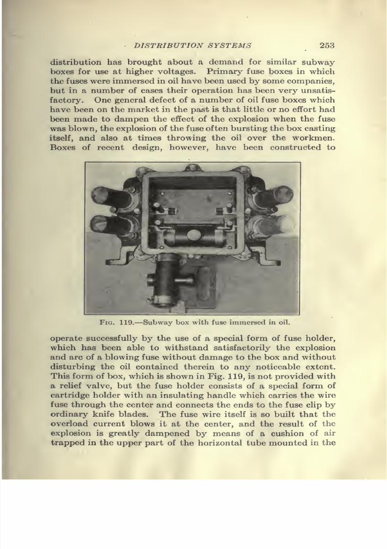
7/28/2019 Underground Trans 00 Me Yeu of t
http://slidepdf.com/reader/full/underground-trans-00-me-yeu-of-t 265/327
• DISTRIBUTION SYSTEMS 253
distribution has brought about a demand for similar subway-
boxes for use at higher voltages. Primary fuse boxes in which
the fuses were immersed in oil have been used by some companies,
but in a number of cases their operation has been very unsatis-
factory. One general defect of a number of oil fuse boxes which
have been on the market in the past is that little or no effort had
been made to dampen the effect of the explosion when the fuse
was blown, the explosion of the fuse often bursting the box casting
itself, and also at times throwing the oil over the workmen.
Boxes of recent design, however, have been constructed to
Vu;. 119.—Subway box witli fuse immersed in oil.
operate successfully by the use of a special form of fuse holder,
which has been able to withstand satisfactorily the explosion
and arc of a blowing fuse without damage to the box and without
disturbing the oil contained therein to any noticeable extent.
This form of box, which is shown in Fig. 119, is not provided with
a relief valve, but the fuse holder consists of a special form of
cartridge holder with an insulating handle which carries the wire
fuse through the center and connects the ends to the fuse clip by
ordinary knife blades. The fuse wire itself is so built that the
overload current blows it at the center, and the result of the
explosion is greatly dampened by means of a cushion of air
trapped in the upper part of the horizontal tube mounted in the
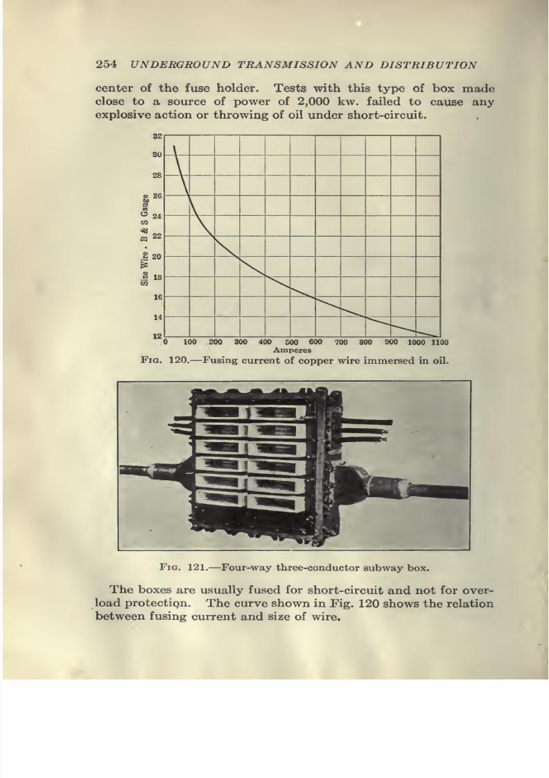
7/28/2019 Underground Trans 00 Me Yeu of t
http://slidepdf.com/reader/full/underground-trans-00-me-yeu-of-t 266/327
254 UNDERGROUND TRANSMISSION AND DISTRIBUTION
center of the fuse holder. Tests with this type of box made
close to a source of power of 2,000 kw. failed to cause any
explosive action or throwing of oil under short-circuit.
100 200 300 400 500 600 700 800 900 1000 1100
Amperes
Fig. 120.—Fusing current of copper wire immersed in oil.
Fig. 121.—Four-way three-conductor subway box.
The boxes are usually fused for short-circuit and not for over-
load protectign. The curve shown in Fig. 120 shows the relation
between fusing current and size of wire.
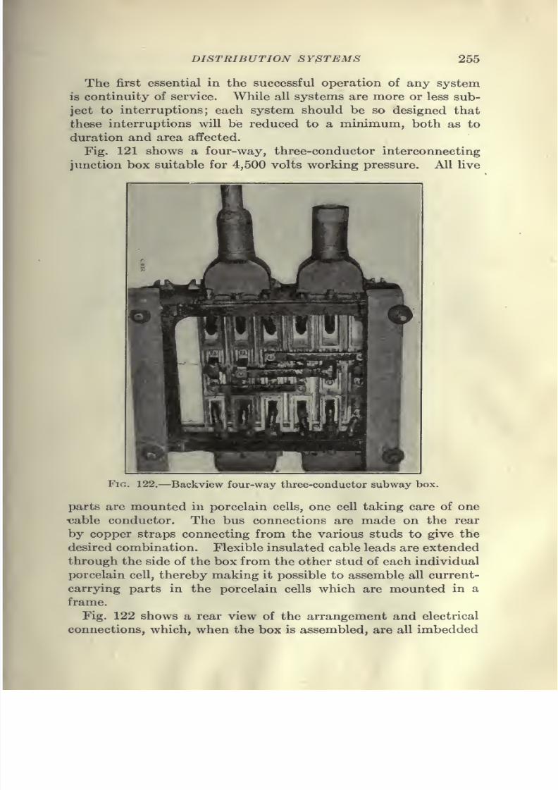
7/28/2019 Underground Trans 00 Me Yeu of t
http://slidepdf.com/reader/full/underground-trans-00-me-yeu-of-t 267/327
DISTRIBUTION SYSTEMS 255
The first essential in the successful operation of any system
is continuity of service. While all systems are more or less sub-
ject to interruptions; each system should be so designed that
these interruptions will be reduced to a minimum, both as to
duration and area affected.
Fig. 121 shows a four-way, three-conductor interconnecting
junction box suitable for 4,500 volts working pressure. All live
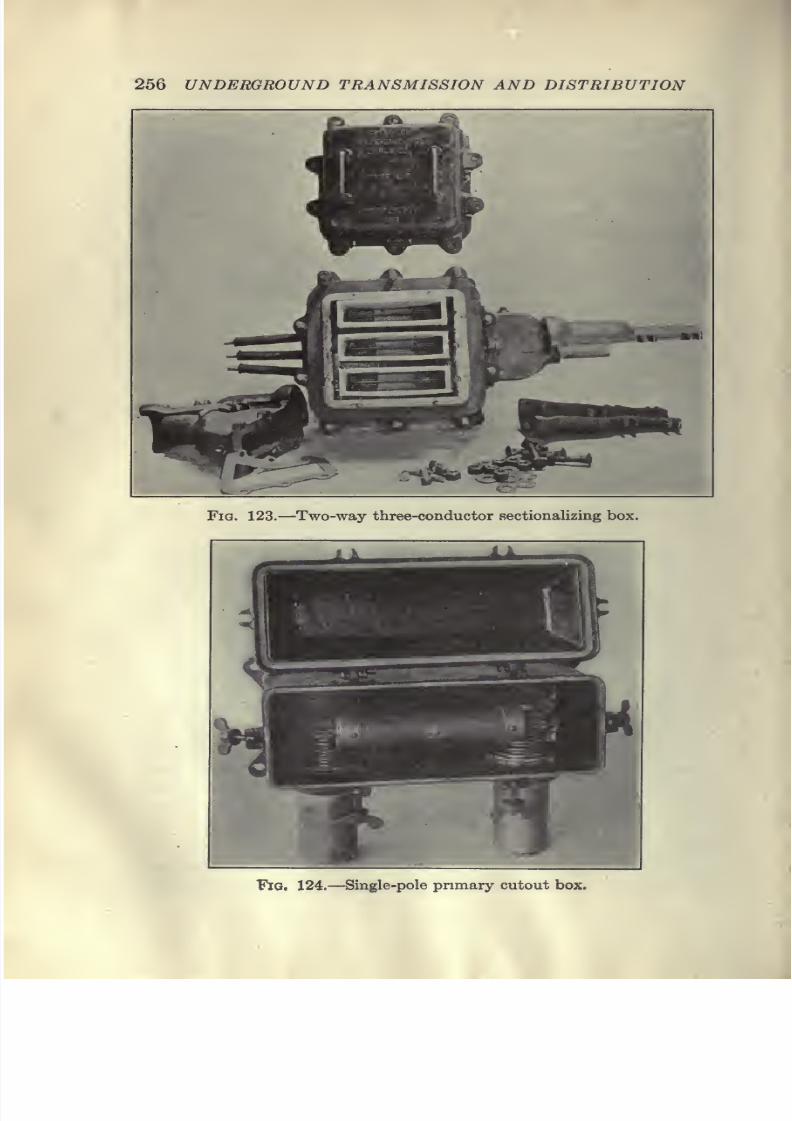
7/28/2019 Underground Trans 00 Me Yeu of t
http://slidepdf.com/reader/full/underground-trans-00-me-yeu-of-t 268/327
256 UNDERGROUND TRANSMISSION AND DISTRIBUTION
Fig. 123.—Two-way three-conductor sectionalizing box.
"Fig. 124.—Single-pole primary cutout box.
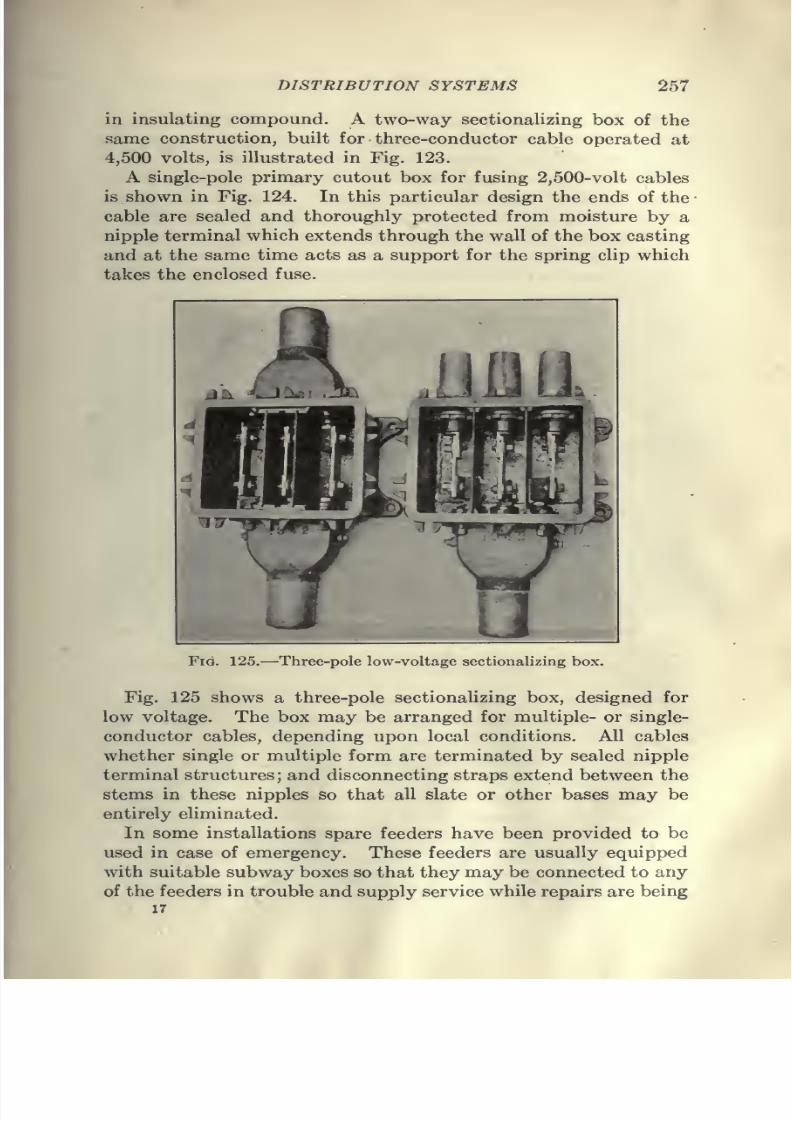
7/28/2019 Underground Trans 00 Me Yeu of t
http://slidepdf.com/reader/full/underground-trans-00-me-yeu-of-t 269/327
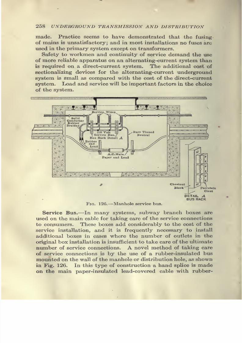
7/28/2019 Underground Trans 00 Me Yeu of t
http://slidepdf.com/reader/full/underground-trans-00-me-yeu-of-t 270/327
258 UNDERGROUND TRANSMISSION AND DISTRIBUTION
made. Practice seems to have demonstrated that the fusing
of mains is unsatisfactory; and in most installations no fuses are
used in the primary system except on transformers.
Safety to workmen and continuity of service demand the use
of more reliable apparatus on an alternating-current system than
is required on a direct-current system. The additional cost of
sectionalizing devices for the alternating-current underground
system is small as compared with the cost of the direct-current
system. Load and service will be important factors in the choice
of the system.
Fig. 126.—Manhole service bus.
Service Bus.—In many systems, subway branch boxes are
used on the main cable for taking care of the service connections
to consumers. These boxes add considerably to the cost of the
service installation, and it is frequently necessary to install
additional boxes in cases where the number of outlets in the
original box installation is insufficient to take care of the ultimate
number of service connections. A novel method of taking care
of service connections is by the use of a rubber-insulated bus
mounted on the wall of the manhole or distribution hole, as shown
in Fig. 126. In this type of construction a hand splice is made
on the main paper-insulated lead-covered cable with rubber-
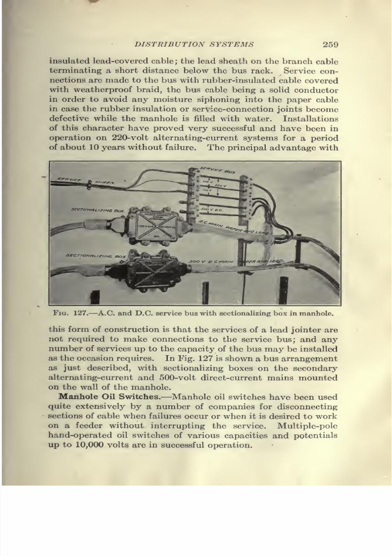
7/28/2019 Underground Trans 00 Me Yeu of t
http://slidepdf.com/reader/full/underground-trans-00-me-yeu-of-t 271/327
DISTRIBUTION SYSTEMS 269
insulated lead-covered cable; the lead sheath on the branch cable
terminating a short distance below the bus rack. Service con-
nections are made to the bus with rubber-insulated cable covered
with weatherproof braid, the bus cable being a solid conductor
in order to avoid any moisture siphoning into the paper cable
in case the rubber insulation or service-connection joints become
defective while the manhole is filled with water. Installations
of this character have proved very successful and have been in
operation on 220-volt alternating-current systems for a period
of about 10 years without failure. The principal advantage with
Fig. 127.—A.C. and D.C. service bus with scctionalizing box in manhole.
this form of construction is that the services of a lead jointer are
not required to make connections to the service bus; and any
number of services up to the capacity of the bus may be installed
as the occasion requires. In Fig. 127 is shown a bus arrangement
as just described, with sectionalizing boxes on the secondary
alternating-current and 500-volt direct-current mains mounted
on the wall of the manhole.Manhole Oil Switches.—Manhole oil switches have been used
quite extensively by a number of companies for disconnecting
sections of cable when failures occur or when it is desired to work
on a feeder without interrupting the service. Multiple-pole
hand-operated oil switches of various capacities and potentials
up to 10,000 volts are in successful operation.
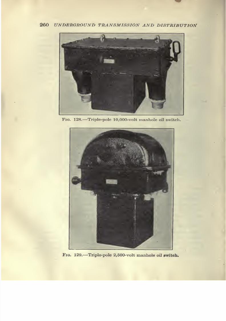
7/28/2019 Underground Trans 00 Me Yeu of t
http://slidepdf.com/reader/full/underground-trans-00-me-yeu-of-t 272/327
260 UNDERGROUND TRANSMISSION AND DISTRIBUTION
Fig. 128.—Triple-pole 10,000-volt manhole oil switch.
FiQ. 129.—Triple-pole 2,500-volt manhole oil switch.
7/28/2019 Underground Trans 00 Me Yeu of t
http://slidepdf.com/reader/full/underground-trans-00-me-yeu-of-t 273/327
DISTRIBUTION SYSTEMS 261
These switches are made for mounting on flat vertical surfaces
in manholes or in locations where there is danger of flooding.
The frame, cover and oil vessel are cast iron, and by means of
gaskets, all joints are made water-tight. The switch is provided
with an operating handle on the outside of the frame of such
design that the switch can be opera+ed with a hook.
Manhole automatic overload switches are not recommended
due to the effect of low temperature on the automatic features
and the tendency of the oil to congeal or thicken at extremely
low temperatures. While the thickening of the oil would not
interfere with the opening and closing of a non-automatic hand-
operated switch, automatic switches must depend in a large
measure upon gravity as the actuating force in opening, and the
thickened oil would have a tendency to delay or entirely pre-
vent the opening of the switch. Further, the gases generated
by an automatic switch in opening the circuit under short-circuit
conditions would, in spite of any vent which might be provided,
have a deteriorating effect upon the gaskets, with consequent
danger of water getting into the switch and causing serious
damage. In Figs. 128 and 129 two types of manhole oil switches
are shown.
Alternating-current Network Protector.—The use of the alter-
nating-current network has become standard practice in sections
where the load is dense. This system has the advantage of
permitting the use of a smaller number of transformers, a more
economical loading of the transformers and a greater flexibility
in the distribution system.
The principal diSiculty which has attended the interconnec-
tion of transformer secondaries has been the progressive blowing
of fuses when a defect developed in any of the transformers.
In the case of a failure not only does the transformer drop its
load but the defect develops into a short-circuit into which all
the other transformers feed, with the result that the fuses blow
progressively, starting with those nearest the fault, until the whole
network is shut down.To eliminate the disadvantages of the network there has been
developed commercially a device known as the "A.C. Network
Protector" designed to disconnect automatically a faulty
transformer.
This device, which has no moving parts to stick or get out of
order, consists of a small transformer with primary and secondary
7/28/2019 Underground Trans 00 Me Yeu of t
http://slidepdf.com/reader/full/underground-trans-00-me-yeu-of-t 274/327
262 UNDERGROUANSND TEMISSION AND DISTRIBUTION
Fig. 130.—A.C. network protector.
v3 W/f^EI SECONDARY
CUKRCNTTKANSFOKM£R'>
ruses-
_S
Vwww
wummm
KANSrO/fMCK
Fia. 131.—Connections of A.C. network protector for three-wire network.
7/28/2019 Underground Trans 00 Me Yeu of t
http://slidepdf.com/reader/full/underground-trans-00-me-yeu-of-t 275/327
DISTRIBUTION SYSTEMS 263
windings in series with the corresponding windings in the power
transformer, and a third coil wound on the iron core. The wind-
ings are so designed that under normal conditions the ampere-turns in one coil neutralize those in the other and the flux in the
core is zero. When a defect develops and there is a reversal of
current in the secondary, the ampere-turns add their effects
together, producing a heavy flux in the iron core, upon which is
wound the third coil consisting of a few turns of heavy-wire
short-circuited through a V-fuse. This flux sets up in the local
circuit a heavy current which instantly blows the fuse and
isolates the faulty transformer.
Fig. 130 shows the general appearance of the protector; and
Fig. 131 shows a diagram of connections for use on a three-wire
system.
Service Connections jfrom Underground Mains.—The central
station, in furnishing service to all classes of consumers under
varying conditions, is required in many installations to change
existing overhead services to an underground system of dis-
tribution. In some cases the entire cost of making the changefrom overhead to underground is borne by the customer, and in
other cases the company bears the entire cost, the practice fol-
lowed being dependant on local conditions. It is the practice
of some of the larger central-station companies to issue "Rules
and Regulations for Wiring" to the end that wiring contractors
doing construction work for customers to be connected to the
company's mains will so arrange and carry out their work as to
protect the interests of customers and at the same time conformto such regulations as experience has shown are necessary in
order for the company to supply uniform and satisfactory
service.
Wherever it is desired to supply cm-rent from underground
mains, the customers' wiring should terminate and the meter-
board be placed at the front wall of cellar or vault nearest the
street. In some cases where wiring is done by local contractors
andservice is
not actually being supplied from subways at thetime service is desired, the central station companies require an
additional temporary overhead service to be installed until the
underground system is provided.
Armored Services.—In the early periods of underground con-
struction, the service end of the system was somewhat neglected
and very Uttle thought was given to the real importance of an
7/28/2019 Underground Trans 00 Me Yeu of t
http://slidepdf.com/reader/full/underground-trans-00-me-yeu-of-t 276/327
264 UNDERGROUND TRANSMISSION AND DISTRIBUTION
ideal service installation. Services were usually treated as an
adjunct to the main system and no special attention was given
to the installation as long as the connection was made with the
property to be served.
As the underground system increased, the matter of adequate
protection at the consumer's end of services was taken up by the
underwriters with the result that certain rules and regulations
were formulated governing the methods of installation. At
first many companies made their service connections with lead-
covered cable which was buried in the ground. This, of course,
proved impractical, as a failure in the cable necessitated the
tearing up of both the street and sidewalk in effecting repairs.
Another method of furnishing service was to bring the feed into
a building at a street intersection extending it to adjacent build-
ings through the various cellars. The objections to this type
of service were that it materially increased the fire hazard and
the danger of interruptions to service and afforded ample means
for the unscrupulous to obtain current by theft.
There are many other arguments against the installation ofsuch services but the three previously mentioned were sufficient
to condemn such practice and to show clearly the need for indi-
vidual service connections. The next step was the installation
of individual services consisting of iron pipe or duct through which
the cable was drawn. Fire risk, however, was not materially
reduced until a few years ago when it was realized that the old
type of terminal block was inadequate. These terminal blocks
consisted of an ordinary fuse block which was not protected
against dampness nor against short-circuits caused by accidental
contact.
The writer recalls a case in a large eastern city where an investi-
gation of service trouble showed that a serious short-circuit had
been caused by the piling against the fuse block of a number of
steel-banded packing cases filled with fireworks. There are
still such services in existence but central-station companies are
gradually ehminating them, and with the advance in design of
equipment for underground services to meet the severe operating
conditions, a water-tight service box with enclosed fuses was
produced. This equipment was installed adjacent to the duct
holding the service wires which were carried by knobs or cleats
to the service box where porcelain-bushed holes provided an
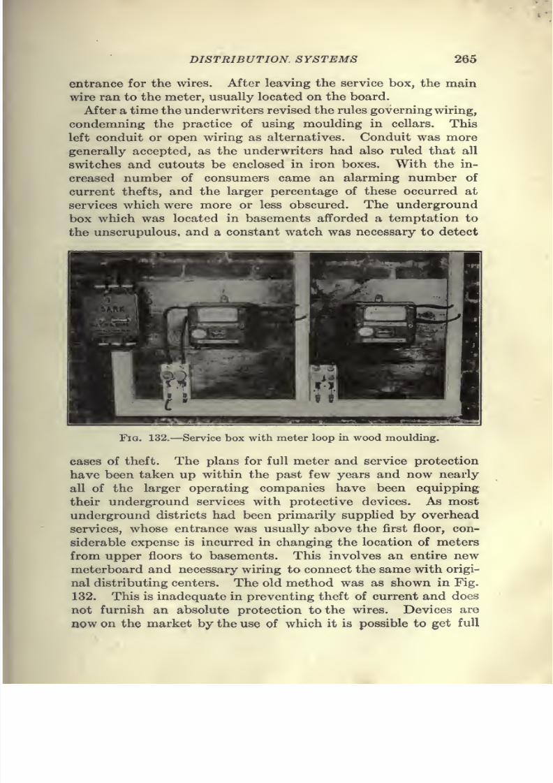
7/28/2019 Underground Trans 00 Me Yeu of t
http://slidepdf.com/reader/full/underground-trans-00-me-yeu-of-t 277/327
DISTRIBUTION SYSTEMS 265
entrance for the wires. After leaving the service box, the main
wire ran to the meter, usually located on the board.
After a time the underwriters revised the rules governing wiring,
condemning the practice of using moulding in cellars. This
left conduit or open wiring as alternatives. Conduit was more
generally accepted, as the underwriters had also ruled that all
switches and cutouts be enclosed in iron boxes. With the in-
creased number of consumers came an alarming number of
current thefts, and the larger percentage of these occurred at
services which were more or less obscured. The underground
box which was located in basements afforded a temptation to
the unscrupulous, and a constant watch was necessary to detect
Fig. 132.—Service box with meter loop in wood moulding.
cases of theft. The plans for full meter and service protection
have been taken up within the past few years and now nearly
all of the larger operating companies have been equipping
their underground services with protective devices. As most
underground districts had been primarily supplied by overhead
services, whose entrance was usually above the first floor, con-
siderable expense is incurred in changing the location of metersfrom upper floors to basements. This involves an entire new
meterboard and necessary wiring to connect the same with origi-
nal distributing centers. The old method was as shown in Fig.
132. This is inadequate in preventing theft of current and does
not furnish an absolute protection to the wires. Devices are
now on the market by the use of which it is possible to get full

7/28/2019 Underground Trans 00 Me Yeu of t
http://slidepdf.com/reader/full/underground-trans-00-me-yeu-of-t 278/327
266 UNDERGROUND TRANSMISSION AND DISTRIBUTION
protection from theft as well as to provide an absolutely iron-
clad service at a very slight cost over that of open-wired boards.
Such boards have many additional features for facilitating the
handling and testing of meters in service. An ideal board, as
used by some of the larger operating companies, can be con-
structed at a very reasonable cost.
In changing over from the old overhead to new underground
installations, considerable wiring is necessary to connect new ser-
vices to points of distribution. When making such changes in
large buildings it is advisable to bring all meters to a point ad-
jacent to the service. The following is an outline of the methodemployed by a few of the companies making extensive changes
from overhead to underground systems.
Prior to starting the actual work, a service inspector is sent
out to select the most advantageous point to make the service
entrance. In making this selection attention must be given to
the physical conditions outside of the building, such as location
of hydrants, poles and other obstructions which would interfere
with service pipes. After having familiarized himself with theoutside, he selects the most desirable point for the location of the
service entrance, choosing the point, where possible, which is
least likely to be obstructed by an accumulation of material
usually found in cellars. If sufficient wall space can be secured at
the point of entrance of service, the meterboard will be located
at that point unless a large amount of interior wiring is involved.
Should this be the case, a meter location is selected which will
allow a more economical installation by eliminating some of the
wiring. Such a case would be where there are a number of meters
located at various points in a building.
After the service pipe is installed, the interior wiring changes
are started. Service wire is pulled in as the first step, and the
service board is mounted at the point selected. The best form
of meterboard is constructed of angle iron made up in the form
of a frame, upon which may be mounted backboards to support
meters. If service and meters are to be located at the same point,
an approved water-tight service box is bolted to the side of the
frame. Service wires are calked in the service pipe with oakum
soaked in a sealing compound to exclude gases. Service wires
are then incased in a flexible-steel conduit, one end of which is
pushed back in the service pipe until it reaches the calking. To the
other end is attached a connector which is made up to a fitting
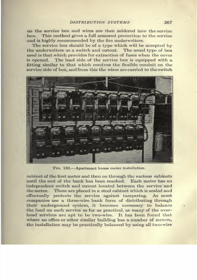
7/28/2019 Underground Trans 00 Me Yeu of t
http://slidepdf.com/reader/full/underground-trans-00-me-yeu-of-t 279/327
DISTRIBUTION SYSTEMS 267
on the service box and wires are then soldered into the service
box. This method gives a full armored protection to the service
and is highly recommended by the fire underwriters.
The service box should be of a type which will be accepted by
the underwriters as a switch and cutout. The usual type of box
used is that which provides for extraction of fuses when the cover
is opened. The load side of the service box is equipped with a
fitting similar to that which receives the flexible conduit on the
service side of box, and from this the wires are carried to the switch
Fig. 133.—Apartment house meter installation.
cabinet of the first meter and then on through the various cabinets
until the end of the bank has been reached. Each meter has an
independent switch and cutout located between the service and
the meter. These are placed in a steel cabinet which is sealed and
effectually protects the service against tampering. As most
companies use a three-wire bank form of distributing through
their underground system, it becomes necessary to balance
the load on each service as far as practical, as many of the over-
head services are apt to be two-wire. It has been found that
where an office or other similar building has a number of meters,
the installation may be practically balanced by using all two-wire
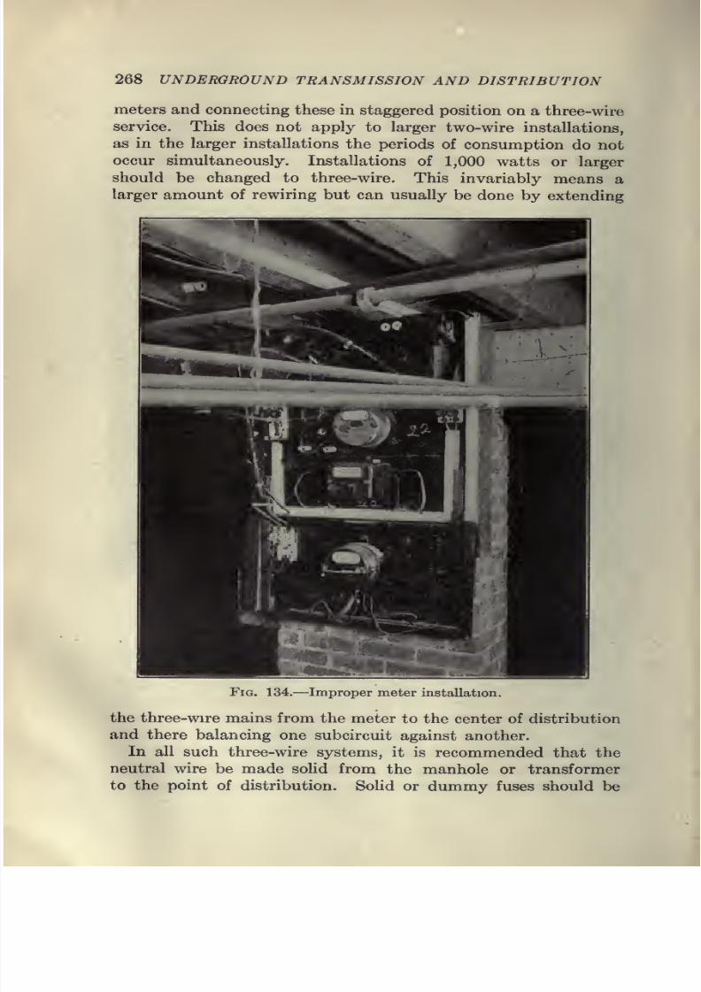
7/28/2019 Underground Trans 00 Me Yeu of t
http://slidepdf.com/reader/full/underground-trans-00-me-yeu-of-t 280/327
268 UNDERGROUND TRANSMISSION AND DISTRIBUTION
meters and connecting these in staggered position on a three-wire
service. This does not apply to larger two-wire installations,
as in the larger installations the periods of consumption do not
occur simultaneously. Installations of 1,000 watts or larger
should be changed to three-wire. This invariably means a
larger amount of rewiring but can usually be done by extending
Fig. 134,—Improper meter installation.
the three-wire mains from the meter to the center of distribution
and there balancing one subcircuit against another.
In all such three-wire systems, it is recommended that the
neutral wire be made solid from the manhole or transformer
to the point of distribution. Sohd or dummy fuses should be
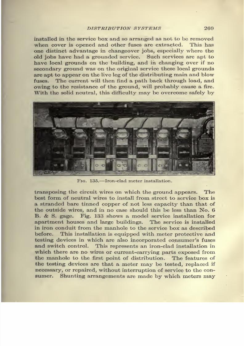
7/28/2019 Underground Trans 00 Me Yeu of t
http://slidepdf.com/reader/full/underground-trans-00-me-yeu-of-t 281/327
DISTRIBUTION SYSTEMS 260
installed in the service box and so arranged as not to be removed
when cover is opened and other fuses are extracted. This has
one distinct advantage in changeover jobs, especially where the
old jobs have had a grounded service. Such services are apt to
have local grounds on the building, and in changing over if no
secondary ground was on the original service these local grounds
are apt to appear on the live leg of the distributing main and blow
fuses. The current will then find a path back through load, and
owing to the resistance of the ground, will probably cause a fire.
With the solid neutral, this difficulty may be overcome safely by
Fig. 135.—Iron-clad meter installation.
transposing the circuit wires on which the ground appears. Thebest form of neutral wires to install from street to service box is
a stranded bare tinned copper of not less capacity than that of
the outside wires, and in no case should this be less than No. 6
B. & S. gage. Fig. 133 shows a model service installation for
apartment houses and large buildings. The service is installed
in iron conduit from the manhole to the service box as described
before. This installation is equipped with meter protective and
testing devices in which are also incorporated consumer's fusesand switch control. This represents an iron-clad installation in
which there are no wires or current-carrying parts exposed from
the manhole to the first point of distribution. The features of
the testing devices are that a meter may be tested, replaced if
necessary, or repaired, without interruption of service to the con-
sumer. Shunting arrangements are made by which meters may
7/28/2019 Underground Trans 00 Me Yeu of t
http://slidepdf.com/reader/full/underground-trans-00-me-yeu-of-t 282/327
270 UNDERGROUND TRANSMISSION AND DISTRIBUTION
be entirely isolated from the line for purpose of repairs or changes,
thus eliminating danger to the operator. It is also possible to
discontinue service for non-payment or other causes and lock
same out until such time as it becomes desirable to reinstate
service. This is very convenient where there is a change of
tenants and it is desirable to make a meter transfer. Fig. 134
shows a job which was changed over and shows the hazardous
condition of wires both from a fire and theft of current standpoint.
Many old installations have reached such a condition and should
be rebuilt.
Fig. 135 shows a service equipped with armor. Such in-
stallations as are shown in Fig. 135 can be made for less than
$2.50 per meter, which includes complete outfit installed as
shown.
Protection of Transmission Systems.—The growth in the
central-station industry and the use of high-voltage transmission
cable has brought about numerous problems which have made it
necessary to resort to various methods for protection of the
system.
The increase in size of generating and substation equipment,
together with the increase in size and voltage of the connected
cables, has made it exceedingly difficult to handle short-circuit-
ing values. The change from engine-driven units of compara-
tively small capacity and slow speeds to turbine-driven units of
large capacity and high speeds is perhaps one of the largest
factors in the problem.
Experience has shown that no single part of an electrical sys-
tem is free from the possibility of injury, and that it is incumbent
upon operating and designing engineers to protect their systems
as far as possible from such occurrences through the use of pro-
tective devices suitably designed to afford such protection.
Relays.—Oil-break switches and carbon-break circuit-breakers
are commonly used to open electrical circuits at some given
overload and on short-circuit. To secure additional protection
under a variety of abnormal conditions or to provide for a certainpredetermined operation or sequence of operation, relays may be
advantageously employed. The connections between the relays
and circuit-opening devices are usually electrical and are ex-
tremely flexible since they admit of the use of a number of devices,
each having a different function, with a single oil switch or circuit-
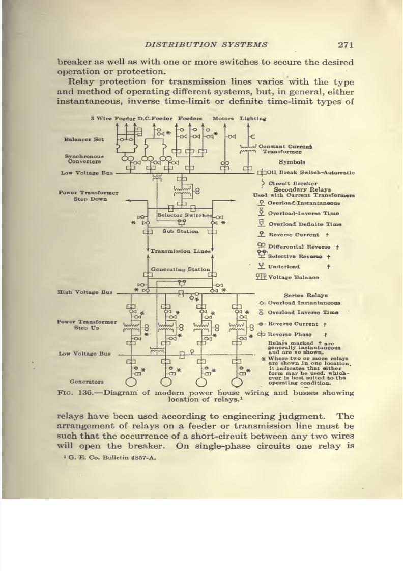
7/28/2019 Underground Trans 00 Me Yeu of t
http://slidepdf.com/reader/full/underground-trans-00-me-yeu-of-t 283/327
DISTRIBUTION SYSTEMS 271
breaker as well as with one or more switches to secure the desired
operation or protection.
Relay protection for transmission lines varies with the type
and method of operating different systems, but, in general, either
instantaneous, inverse time-limit or definite time-limit types of
3 Wire Feeder D.C.Feeder Feeders Motors Lighting
Balancer ^et
SynchronousConverters
Low Voltage Bus
Power Transformer
Step Down
High Voltage Bos
Power Transformer
Step Up
Low Voltage Bus
Generators
VvwUiJ Constant Oarranjk
rr^ Transformex
Symbols
—tL cpOIl. Break .Swltch-Aatoro«tio
p Oircnit Breaker
Secondary Relays
Used with Current Transformers
_2. Overload-Instantaneous
X Overload-Inverse Time
S. Overload Definite Time
S. Reverse Current +
% Differential Reverse f
hJ Selective Berasw t
X Underload t
211Voltage Balance
Series Relays
O- Overload Instantaneous
5 Overload Inverse Time
-O-Beverse Current t
c|o Reverse Phase f
Belays marked f aregenerally instantaueouaand are so shown.
* Where two or more relays
are shown in one location,
it indicates that either
form may be used, which-
ever is best suited to Ihaoperating condltioo.
Fig. 136.—Diagram of modem power touse wiriag and busses showing
location of relays.^
relays have been used according to engineering judgment. The
arrangement of relays on a feeder or transmission line must be
such that the occurrence of a short-circuit between any two wires
will open the breaker. On single-phase circuits one relay is
> G. E. Co. Bulletin 4867-A.
7/28/2019 Underground Trans 00 Me Yeu of t
http://slidepdf.com/reader/full/underground-trans-00-me-yeu-of-t 284/327
272 UNDERGROUND TRANSMISSION AND DISTRIBUTION
sufficient to accomplish this. One of the fundamental condi-
tions beginning to be more fully appreciated by engineers is that
each particular line should be treated individually with respect
to its relay setting instead of having a certain definite setting
for the relays of all lines in a given class.
In order to determine the proper setting of instantaneous over-
load, time-limit and inverse time-limit relays which are more
commonly used on a system of distribution, it is necessary to
know the characteristics of the system as well as the character-
istics of the generators, automatic apparatus, circuit-breakers,
regulators, etc.
In systems operating radial feeders, with each feeder connect-
ing to only one substation and not operating in parallel at sub-
station ends, reasonably satisfactory service has been rendered
by the type of relays referred to.
In systems operating ring systems of feeders, or radial feeders
with several substations in tandem on a single feeder, where
selective action is required in order to prevent interruption of
service from all stations between a fault and the source of power,
satisfactory results have rarely been continuously attained with
any of the types of relays mentioned.
In Fig. 136 is shown a one-line diagram which will be of assist-
ance in making a selection from the various types of relays to
meet the requirements of power-house and substation layouts.
It should be noted that the selection of relays to meet actual
operating conditions is an important problem and should receive
careful attention when a new system is being laid out or exten-
sions are being made to a system already installed.
The successful operation, selective cutting out of trouble, and
the continuity and safety of service, depend entirely on the opera-
tion of automatic oil switches and circuit-breakers, which in turn
must be tripped by means of relays. There are many types of
relays, each type designed to perform certain functions, and
before any of these types are installed, a careful study should be
madeof
the conditions under which they must operate.Current-limiting Reactance Coils.—When short-circuits occur
in the cable system, a tremendous current flow is set up which
reaches its maximum during the first cycle. When it is realized
that for this first cycle every generator connected to the bus is
able to assume a short-circuiting value of at least ten times its
rated capacity, it is readily seen that heavy stresses are imposed
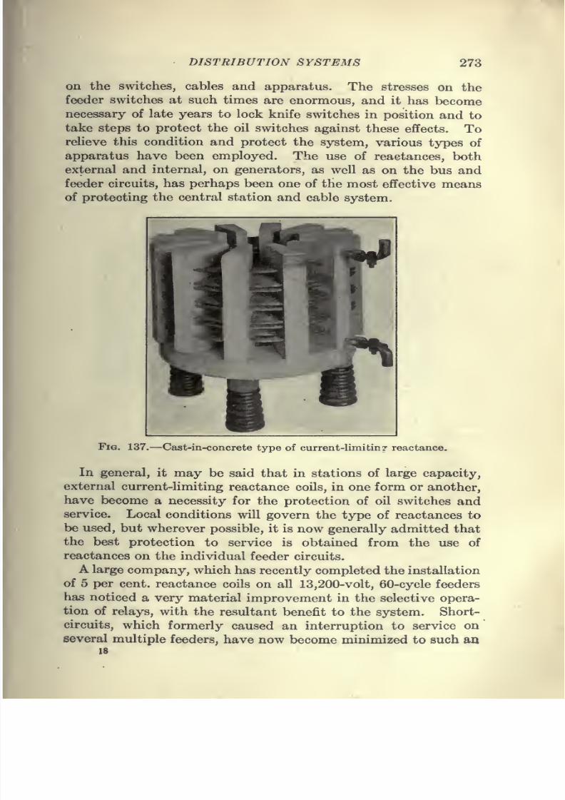
7/28/2019 Underground Trans 00 Me Yeu of t
http://slidepdf.com/reader/full/underground-trans-00-me-yeu-of-t 285/327
DISTRIBUTION SYSTEMS 273
on the switches, cables and apparatus. The stresses on the
feeder switches at such times are enormous, and it has become
necessary of late years to lock knife switches in position and to
take steps to protect the oil switches against these effects. To
relieve this condition and protect the system, various types of
apparatus have been employed. The use of reactances, both
external and internal, on generators, as well as on the bus and
feeder circuits, has perhaps been one of the most effective means
of protecting the central station and cable system.
Fig. 137.—Cast-in-concrete type of current-limitin? reactance.
In general, it may be said that in stations of large capacity,
external current-limiting reactance coils, in one form or another,
have become a necessity for the protection of oil switches and
service. Local conditions will govern the type of reactances to
be used, but wherever possible, it is now generally admitted that
the best protection to service is obtained from the use of
reactances on the individual feeder circuits.
A large company, which has recently completed the installation
of 5 per cent, reactance coils on all 13,200-volt, 60-cycle feeders
has noticed a very material improvement in the selective opera-
tion of relays, with the resultant benefit to the system. Short-
circuits, which formerly caused an interruption to service on
several multiple feeders, have now become minimized to such anIS
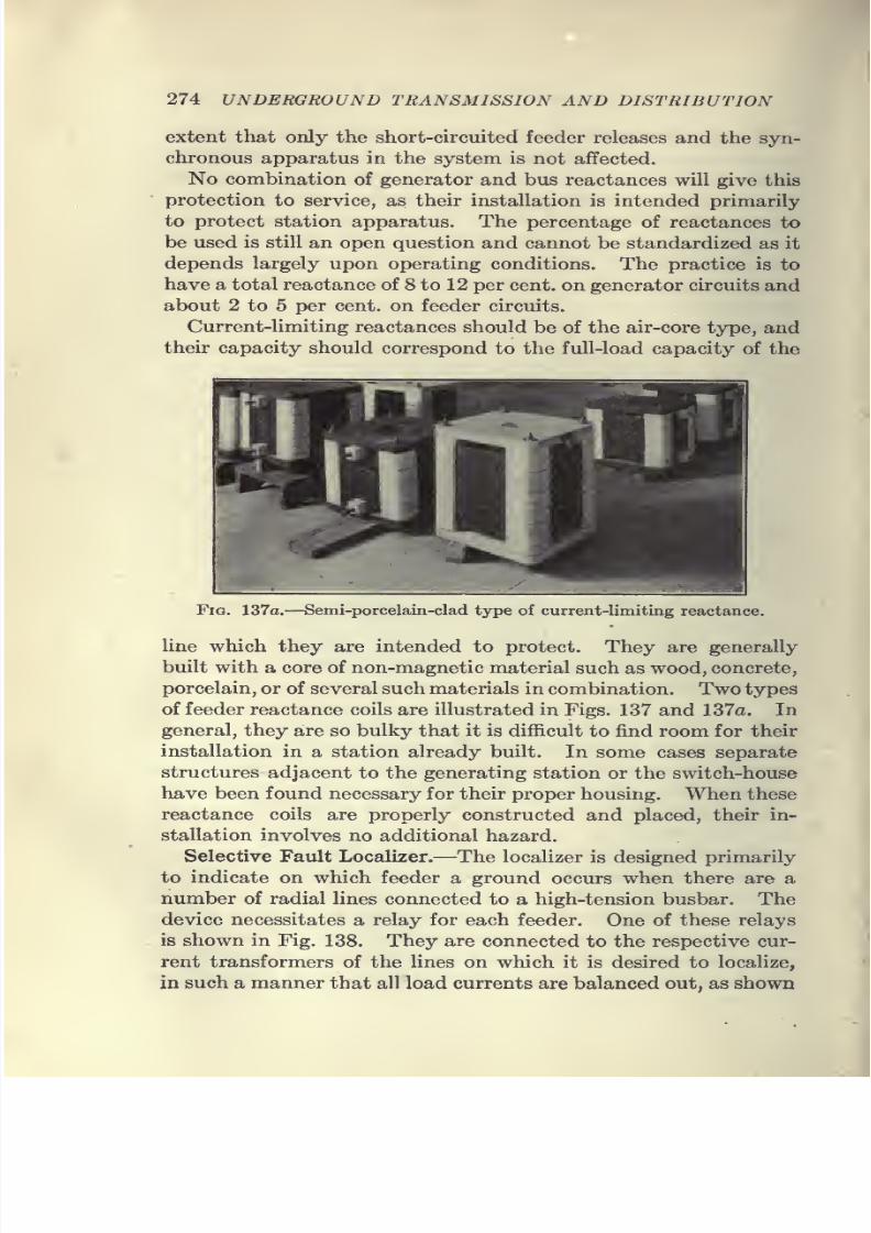
7/28/2019 Underground Trans 00 Me Yeu of t
http://slidepdf.com/reader/full/underground-trans-00-me-yeu-of-t 286/327
274 UNDERGROUND TRANSMISSION AND DISTRIBUTION
extent that only the short-circuited feeder releases and the syn-
chronous apparatus in the system is not affected.
No combination of generator and bus reactances will give this
protection to service, as their installation is intended primarily
to protect station apparatus. The percentage of reactances to
be used is still an open question and cannot be standardized as it
depends largely upon operating conditions. The practice is to
have a total reactance of 8 to 12 per cent, on generator circuits and
about 2 to 5 per cent, on feeder circuits.
Current-limiting reactances should be of the air-core type, and
their capacity should correspond to the full-load capacity of the
FiQ. 137a.—Semi-porcelain-clad type of current-limiting reactance.
line which they are intended to protect. They are generally
built with a core of non-magnetic material such as wood, concrete,
porcelain, or of several such materials in combination. Two types
of feeder reactance coils are illustrated in Figs. 137 and 137a. In
general, they are so bulky that it is difficult to find room for their
installation in a station already built. In some cases separate
structures adjacent to the generating station or the switch-house
have been found necessary for their proper housing. When these
reactance coils are properly constructed and placed, their in-
stallation involves no additional hazard.
Selective Fault Localizer.—The localizer is designed primarilyto indicate on which feeder a ground occurs when there are a
number of radial lines connected to a high-tension busbar. The
device necessitates a relay for each feeder. One of these relays
is shown in Fig. 138. They are connected to the respective cur-
rent transformers of the lines on which it is desired to localize,
in such a manner that all load currents are balanced out, as shown
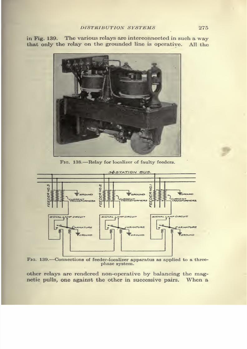
7/28/2019 Underground Trans 00 Me Yeu of t
http://slidepdf.com/reader/full/underground-trans-00-me-yeu-of-t 287/327
DISTRIBUTION SYSTEMS 275
in Fig. 139. The various relays are interconnected in such a way
that only the relay on the grounded line is operative. All the
fFig. 138.—Relay for localizer of faulty feeders.
3^station bus.
= GROUND
rfi^NsroKMCKS
^GROUND >•
CUKKENT Q •
SION^U i-AM^ CIKCUII
^AnM^TUKC -A^MATVWfl
sienj^L. L^M^ciKCurr
r-AKMATuire
Fig. 139.—Connections of feeder-localizer apparatus as applied to a three-
phase system.
other relays are rendered non-operative by balancing the mag-
netic pulls, one against the other in successive pairs. When a
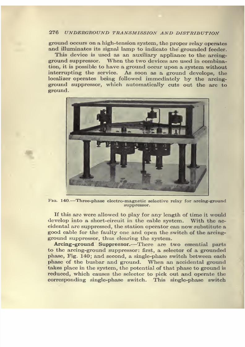
7/28/2019 Underground Trans 00 Me Yeu of t
http://slidepdf.com/reader/full/underground-trans-00-me-yeu-of-t 288/327
276 UNDERGROUND TRANSMISSION AND DISTRIBUTION
ground occurs on a high-tension system, the proper relay operates
and illuminates its signal lamp to indicate the' grounded feeder.
This device is used as an auxihary apphance to the arcing-
ground suppressor. When the two devices are used in combina-
tion, it is possible to have a ground occur upon a system without
interrupting the service. As soon as a ground develops, the
localizer operates being followed immediately by the arcing-
ground suppressor, which automatically cuts out the arc to
ground.
Fig. 140.—Three-phase electro-magnetic selective relay for arcing-ground
suppressor.
If this arc were allowed to play for any length of time it would
develop into a short-circuit in the cable system. With the ac-
cidental arc suppressed, the station operator can now substitute a
good cable for the faulty one and open the switch of the arcing-
ground suppressor, thus clearing the system.
Arcing-ground Suppressor.—There are two essential parts
to the arcing-ground suppressor: first, a selector of a grounded
phase. Fig. 140; and second, a single-phase switch between each
phase of the busbar and ground. When an accidental ground
takes place in the system, the potential of that phase to ground is
reduced, which causes the selector to pick out and operate the
corresponding single-phase switch. This single-phase switch

7/28/2019 Underground Trans 00 Me Yeu of t
http://slidepdf.com/reader/full/underground-trans-00-me-yeu-of-t 289/327
DISTRIBUTION SYSTEMS 277
extinguishes the arc no matter where it occurs on the sysfem,
and thus stops further development of the trouble as well as
preventing surges which accompany an arcing ground. When a
substitute cable is switched in, the faulty cable is taken out and
then the switch of the arcing-ground suppressor is opened. The
single-phase switches are designed with two contacts in series,
with resistances between contacts. A circuit is never made nor
broken without this resistance in series to damp out oscillations.
Grounded-neutral Systems.—Some companies in order to
gain additional protection operate on a grounded-neutral system,
while others resort to the use of various types of arcing-ground
suppressors. The practice of grounding the neutral on trans-
mission systems has not so far been standardized, and it is the
practice of some companies to operate with the neutral free from
ground, while others ground the neutral through varying amounts
of resistance, and in still other cases the neutral is grounded
without any resistance.
In a system with the neutral ungrounded, when one conductor
becomes grounded, the arc may establish and extinguish itself
in rapid succession, creating an arcing ground which would have
been eliminated if the neutral had been grounded. The presence
of an arcing ground of high-frequency oscillation is liable to
create surges destructive to the cable and apparatus. Where
the neutral is grounded through a resistance, the high-frequency
voltage between two of the conductors and ground is minimized
when the other conductor is grounded. This same result is
accompHshed also in an ungrounded system by the use of anarcing-ground suppressor, when the faulty conductor is grounded
through the suppressor switch. This operation is accomplished
in a fraction of a second and eliminates the arcing ground and
with it the attending high-frequency voltage, thus leaving the
cable with line voltage between the other two conductors and
ground. This operation causes no interruption to the system,
and the faulty feeder may be taken out of service at leisure.
Another feature of the arcing-ground suppressor is that in cases
of accidental contacts with the bus by employees working in
the vicinity, the suppressor may act with sufficient promptness
to prevent fatal accidents. A number of instances of this kind
have been reported to the writer.
In the grounded system the voltage to ground decreases as the
resistance between the neutral and ground decreases, and ia-

7/28/2019 Underground Trans 00 Me Yeu of t
http://slidepdf.com/reader/full/underground-trans-00-me-yeu-of-t 290/327
278 UNDERGROUND TRANSMISSION AND DISTRIBUTION
creases as the generator capacity increases. It is necessary to
decrease the resistance in the neutral as the capacity of the
system increases in order to confine the voltage strains to the samelimits. But since the current that can flow over a short-circuit
between one conductor and ground may be limited by the
resistance in the neutral, most of the companies using the resist-
ance prefer, in case one conductor becomes grounded, to use
such resistance as will allow the necessary current to flow to
operate the relays properly without regard to the voltage rise.
In expanding the idea of decreasing the resistance between the
neutral and ground in order to minimize the voltage strains to
ground, one large company, after operating with the neutral,
grounded through a resistance for several years, has decided to
ground the neutral without resistance. Under this condition,
when one conductor becomes grounded, the current on that con-
^S l.£l9D3H£ATH
Fig. 141.
f/iZ' fYlPeR INSUL/ITION
6/3z'fyif£K INSULMTION
•^64 PffPEH INSUt-ftTION
-350,000 cm. 13,200-volt split-conductor paper insulated-sector
cable.
ductor approximates that flowing over a short-circuit between
conductors, which will cause the selective relays to operate in
the same manner as when a short-circuit occurs between con-
ductors, the condition for which the relays are set.
There is considerable difference of opinion regarding the
advisability of grounding the neutral and the relative advantages
and disadvantages resulting therefrom. For more detailed
information regarding the practice of grounding the neutral and
the operation of arcing-ground suppressors, the reader is referred
to the Proceedings of the American Institute of Electrical
Engineers.
Merz System of Cable Protection.—The Merz system of cable
protection consists of the usual equipment of current trans-
formers, relays and oil switches, but the current transformers at
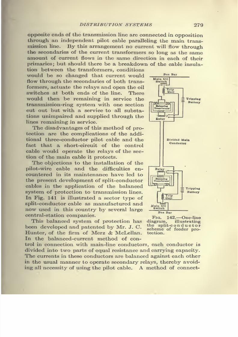
7/28/2019 Underground Trans 00 Me Yeu of t
http://slidepdf.com/reader/full/underground-trans-00-me-yeu-of-t 291/327
DISTRIBUTION SYSTEMS 279
Main Oil I
Switch
TripCoil
Belay
g Tripping
Battery
DividedMala
Conductor
opposite ends of the transmission line are connected in opposition
through an independent pilot cable paralleling the main trans-
mission Hne. By this arrangement no current will flow throughthe secondaries of the current transformers so long as the same
amount of current flows in the same direction in each of their
primaries; but should there be a breakdown of the cable insula-
tion between the transformers, conditions
would be so changed that current would
flow through the secondaries of both trans-
formers, actuate the relays and open the oil
switches at both ends of the line. Therewould then be remaining in service the
transmission-ring system with one section
cut out but with a service to all substa-
tions unimpaired and supplied through the
lines remaining in service.
The disadvantages of this method of pro-
tection are the comphcations of the addi-
tional three-conductor pilot cable and thefact that a short-circuit of the control
cable would operate the relays of the sec-
tion of the main cable it protects.
The objections to the installation of the
pilot-wire cable and the difficulties en-
countered in its maintenance have led to
the present development of split-conductor
cables in the application of the balancedsystem of protection to transmission lines.
In Fig. 141 is illustrated a sector type of
split-conductor cable as manufactured and
now used in this country by several large
central-station companies.
This balanced system of protection has
been developed and patented by Mr. J. C.
Hunter, of the firm of
Merz &McLellan.
In the balanced-current method of con-
trol in connection with main-line conductors, each conductor is
divided into two parts of equal resistance and carrying capacity.
The currents in these conductors are balanced against each other
in the usual manner to operate secondary relays, thereby avoid-
ing all necessity of using the pilot cable. A method of connect-
Belay
'nlP^Trip
Coil
^ Tripping
Y Battery
Main Oil
SwitchaBus Bar
Fig. 142.—One-linediagram, illustrating
the split-c onductorscheme of feeder pro-
tection.
7/28/2019 Underground Trans 00 Me Yeu of t
http://slidepdf.com/reader/full/underground-trans-00-me-yeu-of-t 292/327
280 UNDERGROUND TRANSMISSION AND DISTRIBUTION
ing a split-conductor scheme of feeder protection is shown in Fig.
142. The general adoption of this type of cable in many trans-
mission undertakings abroad indicates that the advantages to be
derived from its use are considered as effecting material im-
provements in the reliability of service and are, therefore, worthy
of recognition in American practice.
7/28/2019 Underground Trans 00 Me Yeu of t
http://slidepdf.com/reader/full/underground-trans-00-me-yeu-of-t 293/327
CHAPTER IX
ELECTROLYSIS
General.—Electrolysis as here referred to is the chemical
decomposition of metallic structures by electric currents. Soil,
when entirely dry, has a very high resistance, but under normalconditions street soils contain varying amounts of water-holding
salts in solution, thus making the earth a fair conductor of elec-
tricity. The specific resistance of soils varies widely, ranging
from a few hundred ohms per cm,' for moist soils to 25,000 or
30,000 ohms per cm.' in the case of dry sandy soils.
Since it is to a large extent the moisture which makes soil a
conductor, the passage of currents through the earth is by elec-
trolytic conduction, and is accompanied by a decomposition of themetal at the point where the current leaves an underground struc-
ture to take a path of lower resistance throughthe earth. This is
true of both direct and alternating currents except that the rate
of decomposition by an alternating current is only about 1 per
cent, of that caused by a direct current of the same value.
The rate of oxidation is proportional to the current strength,
and from a consideration of the theoretical amount of metal
changedinto
the oxideit will
be seen that eventhough the de-
composition of underground structures does not follow the
electrochemical law exactly, the amount of metal oxidized in a
year is very considerable. The constant for iron (converted into
the ferrous condition) is 1.042, and for lead 3.858 grams per
amp-hr. The amount of iron oxidized in a year will be 1.042 X8,760 X 0.002205 = 20.2 lb. per amp. The amount of lead will
be 3.858 X 8,760 X 0.002205 = 74.1 lb. per year per amp.
Either more or less (but generally less) than this theoretical
amount is realized under actual conditions, depending upon
soil conditions.
The effects of electrolytic action would be far less serious if
this loss of metal were distributed evenly over the structure,
but this unfortunately is not the case. Actually the currents
discharge from a number of small areas, causing pitting. Thus
281
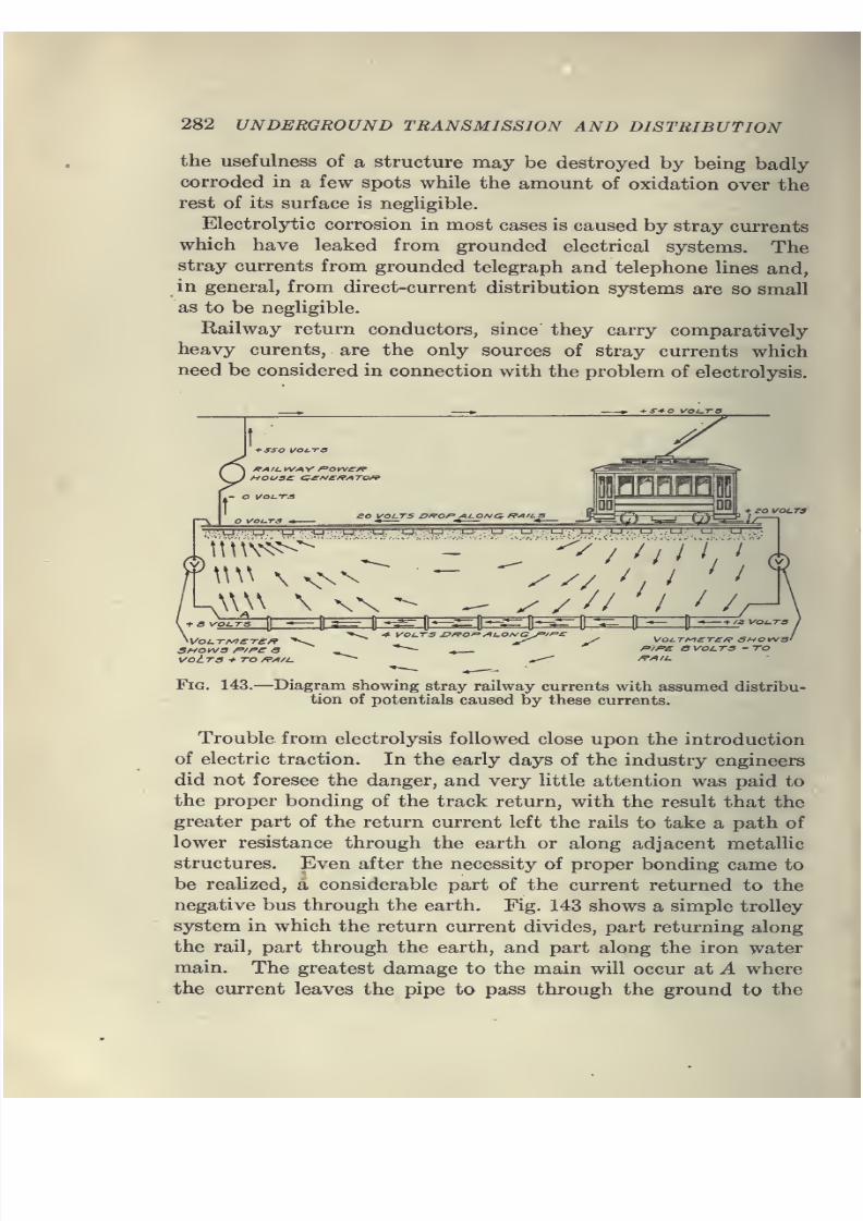
7/28/2019 Underground Trans 00 Me Yeu of t
http://slidepdf.com/reader/full/underground-trans-00-me-yeu-of-t 294/327
282 UNDERGROUND TRANSMISSION AND DISTRIBUTION
the usefulness of a structure may be destroyed by being badly
corroded in a few spots while the amount of oxidation over the
rest of its surface is negligible.
Electrolytic corrosion in most cases is caused by stray currents
which have leaked from grounded electrical systems. Thestray currents from grounded telegraph and telephone lines and,
in general, from direct-current distribution systems are so small
as to be negligible.
Railway return conductors, since they carry comparatively
heavy curents, are the only sources of stray currents which
need be considered in connection with the problem of electrolysis.
ys*o i/o^T-a
i-sso voi.-ra
O VOl-TS
so VOUTS Df^OP AI-ONC^ /fAILS
/Uri'
^-'U "u ^' .^-^^vU:^ ;-u. ' j^, ^u.^:U .^u u :.u :' u./ -u.^lj. .;U tj; .u.
/
^ / /J 'I / /
+ S VOUTS
VOt TS + TO /fVI/A
4- VOUTS I^/^OP ^t.o/\/GJ^/P£ ^-+/a VOI.T3
VOUTf^ETCR SHOW 31
P/P£ B vol.T3 - TO
FiG. 143.—Diagram showing stray railway currents with assumed distribu-
tion of potentials caused by these currents.
Trouble from electrolysis followed close upon the introduction
of electric traction. In the early days of the industry engineers
did not foresee the danger, and very little attention was paid to
the proper bonding of the track return, with the result that the
greater part of the return current left the rails to take a path of
lower resistance through the earth or along adjacent metallic
structures. Even after the necessity of proper bonding came to
be realized, a considerable part of the current returned to the
negative bus through the earth. Fig. 143 shows a simple trolley
system in which the return current divides, part returning along
the rail, part through the earth, and part along the iron water
main. The greatest damage to the main will occur at A where
the current leaves the pipe to pass through the ground to the
7/28/2019 Underground Trans 00 Me Yeu of t
http://slidepdf.com/reader/full/underground-trans-00-me-yeu-of-t 295/327
ELECTROLYSIS 283
negative bus. Corrosion will also occur at the joints, due to the
fact that where the joint resistance is high the current will by-
pass the joint through the earth, returning to the pipe on the
other side.
Before attempting to utilize any of the systems for the mitiga-
tion of electrolysis, attention should be given to the matter of
proper rail bonding and the limiting of the distance between
substations.
Rails may be bonded by the installation of copper ribbon or
wire soldered or brazed to the webs of the rails or by welding
together the ends so as to make practically a continuous rail.
In many installations not only are the separate rail sections
bonded but the two rails or (in the case of a double-track road)
all four rails are electrically connected.
The method of bonding rails by the use of a welding outfit
has been used to a considerable extent and is apparently satisfac-
tory since it provides mechanical reinforcement in addition
to a good electrical connection.
A great deal of attention has been given to the matter of rail
bonding; and since the methods in use to-day produce bonds which
show a conductivity of about 80 per cent, as compared with an
equivalent continuous rail, it is doubtful whether any further
reUef for electrolytic conditions can be expected from attempts
to improve upon the present bonding methods.
The number of, and the distance between, stations or substa-
tions which supply a railway line will govern to a very large
extent the amount of current which will leak to pipe lines or
other foreign structures.
Where too small a number of stations are used to supply
a railway Une, the return current to the negative bus will be large
and the distance between stations comparatively long. These
two factors bring about the condition of excessive voltage drop
along the rails and aggravate the tendency of current to return
through the ground.
American engineers apparantly did not have as thorough a
grasp of the situation as did engineers on the Continent. As
soon as the problem of electrolysis became serious in Eiu-ope,
regulations were adopted limiting the voltage drop between
any two points in the track to about 7 or 8 volts. These regula-
tions forced railway companies to install better bonds, to limit
the distance between stations and, in some cases, to install
7/28/2019 Underground Trans 00 Me Yeu of t
http://slidepdf.com/reader/full/underground-trans-00-me-yeu-of-t 296/327
284 UNDERGROUND TRANSMISSION AND DISTRIBUTION
insulated return feeders, with the result that troubles from
electrolytic corrosion disappeared almost entirely.
American practice, on the other hand, has not sought to
remove the underlying causes of electrolysis but has attempted
merely to relieve acute local conditions. The measures adopted
in this country, in addition to track bonding, have consisted
of "pipe drainage" or bonds to other systems. It must not be
inferred that the drainage system is inherently bad, for up to
the present time it has undoubtedly relieved acute cases of elec-
trolysis and has apparently imposed no serious hardship on the
owners of structures tied in by the bonds. In spite of the results
obtained by the drainage system, it does not cure electrolysis
nor remove the fundamental causes, and it is to be regretted
that the large investment necessary for the development of an
adequate bonding system was not used to develop some positive
cure such as the return-feeder system. It is true that where
a large system has adopted drainage bonds as a remedy the
cost of a change to the return-feeder system would be almost
prohibitive; and the writer believes that in most cases the drain-
age system is very nearly as satisfactory a remedy as the return-
feeder system, provided careful and systematic tests are made.
Drainage Systems.—The aim in all drainage systems is to
lower the potential of the structure with respect to the earth
by draining off the current through metallic bonds. The proper
location for these bonds is determined by tests, and the drainage
conductors are installed at points where the structure is danger-
ously positive to the adjacent track. The current is drainedeither to the track or else direct to the negative railway bus by
means of return feeders. If all the current could be drained from
the structure by means of bonds, the bonding system would be
an excellent means of relieving conditions on the particular
structure so drained. The problem is not solved, however, by
indiscriminate bonding. Drainage of any one structure lowers
its potential with respect to neighboring structures, with the
result that the latter will drain through the ground to the bonded
pipe line. It is, therefore, clear that while bonding may clear up
conditions in one place it may work to the injury of structures
not tied into the network.
Where the drainage bonds are so installed that a pipe line be-
comes a parallel return for the track circuit, it is practically im-
possible to control the amount of current carried on the pipe hne,
7/28/2019 Underground Trans 00 Me Yeu of t
http://slidepdf.com/reader/full/underground-trans-00-me-yeu-of-t 297/327
ELECTROLYSIS 285
and serious overheating may result. If the pipe joints offer a
high resistance, the currentwill
leak around the joint and corrodethe metal at the point where the current passes into the soil. The
use of such bonds to a pipe line where high-resistance joints occur
may place the line in a worse condition than would obtain in the
absence of any bonds at all. In the unbonded condition the
total yearly loss of metal would be greater but under some condi-
tions of bonding the action is localized and intensified so as to
cause the structure to corrode through in a number of places.
In addition to the above objection, the system is notpermanent
in that any radical change in conditions will necessitate a complete
change in the bonding system in the locality affected.
In any system where the pipe parallels the track, the current
will divide approximately in inverse proportion to the resistance;
and in such a system, when the current carried by the pipe be-
comes excessive, the current on the pipe can be decreased only by
an increase in rail conductivity. This method requires the use
of a very costly installation of copper as an auxiliary return.
Excessive currents on pipe lines are a source of danger not only
to the pipe itself but to buildings into which service connections
are run. There are cases on record of very serious overheating
of pipe connections inside buildings. However, this danger is
remote, and is due not to the use of bonds but to the installation
of bonds in the wrong place.
Probably the best way to drain a pipe line is by the installation
of insulated drainage feeders running from the negative bus in the
station to various points on the structure. It is possible by the
use of such a system to control very closely the distribution of
current on the pipe line by varying the resistance of the drainage
leads.
This method is better than the preceding, but all drainage sys-
tems have the disadvantage that with growth in the railway
system it may be necessary to drain very large currents from pipe
lines, and that in many cases the trouble is merely transferred
from one area to another.
Numerous attempts have been made to protect pipe lines from
the effects of electrolysis by means other than the use of bonds.
Protective Coatings.—Protective coatings in the form of
paint, dips of asphalt, coal tar or pitch, and wrappings of paper
or cambric have been used to some extent, but tests have failed
to show that any one method is universally satisfactory.
7/28/2019 Underground Trans 00 Me Yeu of t
http://slidepdf.com/reader/full/underground-trans-00-me-yeu-of-t 298/327
286 UNDERGROUND TRANSMISSION AND DISTRIBUTION
It is difficult to apply any coating so as to obtain a uniform
smooth surface free from pinholes or bare spots. Where these
exist, a pipe line may fail much more quickly than where the pipe
is uncoated due to the fact that corrosion will be localized in
a small number of areas, the effect of electrolytic action being
intensified.
Even if the coating is very carefully applied, it is likely to be
scratched in handling; and after the pipe is laid, blisters often
form on the coating and expose the metal to corrosion.
Insulation in the form of wrappings of cloth or paper fail in
most instances because they are not entirely impervious to mois-
ture. The coating becomes damp in spots and affords a conduct-
ing path, with the result that the pipe fails.
Dips consisting of coal tar or pitch which are applied hot and
allowed to cool and harden on the pipe surface are very likely to
develop cracks. It is possible to make coatings absolutely im-
pervious, but only at an excessive cost. Such an installation re-
quires the construction of a trench in which the pipe is laid, the
pitch being poured in and allowed to cool. This method is
not recommended except in special cases where continuity of
service is of such importance as to make the cost of the installa-
tion a minor consideration.
Cement coverings, even when several inches in thickness,
will not afford certain protection because concrete is not imper-
vious to moisture, and moist concrete is a fairly good conductor.
Electrolytic conditions on a pipe line could be cleared up if
it were possible to cover the pipe with a conducting coating
which would not be corroded when the current passed from the
pipe line into the earth. Most of the non-corrosive metals are
so expensive as to make their use commercially impracticable.
Black oxide, or coke particles in a suitable binder, fulfill the
requirement as regards non-corrosive properties, but the same
difficulties are here encountered as in the use of paints and dips.
It is very difficult to get a uniform surface free from flaws. In
addition, black oxide is electronegative to iron and there is
danger of local galvanic action being set up.
Insulating Joints.—Very beneficial results have attended the
practice of breaking up the electrical continuity of pipe lines by
the use of an insulating medium at every joint. If the installa-
tion cost is too great to warrant the insulation of every joint,
the insulation may be used at greater intervals in the line pro-
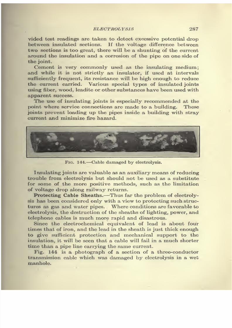
7/28/2019 Underground Trans 00 Me Yeu of t
http://slidepdf.com/reader/full/underground-trans-00-me-yeu-of-t 299/327
ELECTROLYSIS 287
vided test readings are taken to detect ex^^essive potential drop
between insulated sections. If the voltage difference between
two sections is too great, there will be a shunting of the current
around the insulation and a corrosion of the pipe on one side of
the joint.
Cement is very commonly used as the insulating medium;
and while it is not strictly an insulator, if used at intervals
sufficiently frequent, its resistance will be high enough to reduce
the current carried. Various special types of insulated joints
using fiber, wood, leadite or other substances have been used with
apparent success.
The use of insulating joints is especially recommended at the
point where service connections are made to a building. These
joints prevent loading up the pipes inside a building with stray
current and minimize fire hazard.
Fig. 144.—Cable damaged by electrolysis.
Insulating joints are valuable as an auxiliary means of reducing
trouble from electrolysis but should not be used as a substitute
for some of the more positive methods, such as the limitation
of voltage drop along railway returns.
Protecting Cable Sheaths.—Thus far the problem of electroly-
sis has been considered only with a view to protecting such struc-
tures as gas and water pipes. Where conditions are favorable to
electrolysis, the destruction of the sheaths of lighting, power, and
telephone cables is much more rapid and disastrous.
Since the electrochemical equivalent of lead is about four
times that of iron, and the lead in the sheath is just thick enough
to give sufficient protection and mechanical support to the
insulation, it will be seen that a cable will fail in a much shorter
time than a pipe line carrying the same current.
Fig. 144 is a photograph of a section of a three-conductor
transmission cable which was damaged by electrolysis in a wet
manhole.
7/28/2019 Underground Trans 00 Me Yeu of t
http://slidepdf.com/reader/full/underground-trans-00-me-yeu-of-t 300/327
288 UNDERGROUND TRANSMISSION AND DISTRIBUTION
The character of the duct construction will determine to a
large extent the amount of current leaking from railway systems
to the cable sheaths. All duct structures will admit moisture
to a greater or less degree, but fiber duct laid in concrete admits
less than other forms of construction. Where water does enter,
there will in general be an exchange of current either from sheath
to sheath through the concrete or between sheaths and external
structures. It is, therefore, important that duct lines be so
graded as to drain toward manholes, and that, as far as possible,
manholes, be kept dry by drain connections to sewers.
The usual method of protecting cable sheaths is by the use
of a drainage system similar to that used for the protection of
pipe lines. The object of draining the sheaths is to make them
slightly lower in potential than the surrounding earth or neigh-
boring structures, thus preventing current flowing off the sheaths.
Since there is danger of overdraining in making the sheath po-
tential considerably lower that that of ground or adjacent
grounded structures, it is sometimes necessary to insert suitable
resistances in the drainage leads. Overdrained cable sheaths
are a source of danger to neighboring pipe lines because of the
tendency of these lines to be injured by the drainage of their
current to the cable sheaths. To prevent electrolysis of the
sheath of cables by an exchange of current between sheaths,
it is standard practice to attach a common bond in every manhole
which equalizes the sheath potential of all the cables in the
duct line.
It is inadvisable to bond direct to the track or railway return,since this makes a cable system a parallel return to the railway
system. Where bonds are so installed, an accidental high
resistance in the railway return will throw upon the sheaths the
burden of carrying a large part of the return current. This
condition will result in serious overheating of the sheaths and,
in the case of power cables, in a considerable reduction of current-
carrying capacity.
To prevent excessive currentson
cable sheaths, theuse
of
insulating joints in a run of cable is sometimes resorted to. This
method should be used only with great care since there is' danger
of setting up excessive potentials across the joint or between
the sheath and ground. As in the case of insulated pipe joints,
insulated sheath joints are used chiefly to prevent the entrance
of stray currents into buildings through lateral connections.
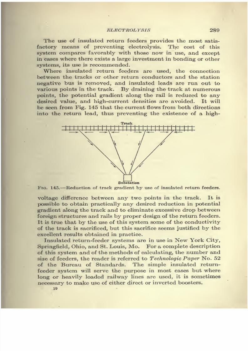
7/28/2019 Underground Trans 00 Me Yeu of t
http://slidepdf.com/reader/full/underground-trans-00-me-yeu-of-t 301/327
ELECTROLYSIS 289
The use of insulated return feeders provides the most satis-
factory means of preventing electrolysis. The cost of this
system compares favorably with those now in use, and except
in cases where there exists a large investment in bonding or other
systems, its use is recommended.
Where insulated return feeders are used, the connection
between the tracks or other return conductors and the station
negative bus is removed, and insulated leads are run out to
various points in the track. By draining the track at numerous
points, the potential gradient along the rail is reduced to any
desired value, and high-current densities are avoided. It will
be seen from Fig. 145 that the current flows from both directions
into the return lead, thus preventing the existence of a high-
Track
Substation
Fig. 145.—Reduction of track gradient by use of insulated return feeders.
voltage difference between any two points in the track. It is
possible to obtain practically any desired reduction in potential
gradient along the track and to eliminate excessive drop between
foreign structures and rails by proper design of the return feeders.
It is true that by the use of this system some of the conductivity
of the track is sacrificed, but this sacrifice seems justified by the
excellent results obtained in practice.
Insulated return-feeder systems are in use in New York City,
Springfield, Ohio, and St. Louis, Mo. For a complete description
of this system and of the methods of calculating, the number and
size of feeders, the reader is referred to Technologic Paper No. 52
of the Bureau of Standards. The simple insulated return-
feeder system will serve the purpose in most cases but where
long or heavily loaded railway lines are used, it is sometimes
necessary to make use of either direct or inverted boosters.
19
7/28/2019 Underground Trans 00 Me Yeu of t
http://slidepdf.com/reader/full/underground-trans-00-me-yeu-of-t 302/327
290 UNDERGROUND TRANSMISSION AND DISTRIBUTION
Another remedial measure has been proposed for the rehef
of electrolysis. This consists in a periodic reversal of polarity
on the railway system; and while this method would theoretically
reduce materially the corrosion, in a large and complicated system,
the operating difficulties would make the scheme impractical
even if the reversal were as infrequent as once in 24 hr.
Other schemes such as the double-trolley and negative-trolley
systems have been proposed. The first is open to the objec-
tion of excessive cost and increased operating difficulties. The
second, while it would undoubtedly delay the ultimate destruc-
tion of other structures, would impose a serious hardship on com-
panies which had installed drainage systems.
General Practice.—A canvass of 56 of the larger lighting companies
operating about 200,000 miles of underground lighting and power cables
yielded the following information as to practice as regards electrolysis
mitigation.
CoNDXnTS
Vitrified-clay tile, of both single and multiple type, is used exclusively by
43 per cent, of the companies. Vitrified tile and indurated fiber is used by
43 per cent, of the companies. In recent years the use of vitrified tile has
been abandoned in favor of fiber in most of these systems. Indurated
fiber is being used exclusively by 12.5 per cent, of the companies. The
remaining 1.5 per cent, is made up of companies who either have not specified
the type of conduit used or else have in use a type which is not yet standard.
The tendency to abandon the use of sectional tile conduit in favor of
fiber is significant. Not only does fiber conduit afford a continuous runway,
but its waterproofing and insulating properties must inevitably serve tominimize the danger of electrolytic corrosion at some point outside of a
manhole where the destruction action might continue undetected until the
cable failed.
Electrolysis
Electrolysis was reported as existing on the cable system by 64 per cent,
of the companies. Evidence that the trouble is confined to isolated cases
is furnished by the fact that in only three instances was electrolysis reported
as generally existent throughout an entire system. The cause of the elec-
trolytic action was in most cases attributed to stray railway currents leaving
the cable shetaths to select paths of lower resistance to the railway return
systems. Two companies state that attempts have been made to remedy
the condition by insulating sections of the cable. Of these, one appears to
have been successful, and the other reports that the trouble still exists in
spite of the fact that each insulated section is drained to a driven ground
connection.
7/28/2019 Underground Trans 00 Me Yeu of t
http://slidepdf.com/reader/full/underground-trans-00-me-yeu-of-t 303/327
ELECTROLYSIS 291
Bonding of Cable Sheaths
The practice of bonding the cable sheaths together as a means of equaliz-
ing sheath potentials and of preventing electrolysis between sheaths of
adjacent cables is shown to be quite general.
Bonds are used by 89 per cent, of the companies, leaving only 11 per cent,
which use no bonds. Except in the case of three companies, which employ
lead strip, the universal practice is either to use copper wire or copper ribbon
sweated directly to the cable sheaths. In one instance a company reports
sweating the bonding ribbon into one end of the cable joint sleeve, a method
which is at once unique and effective.
The necessity of insulating cable sheaths from their supporting racks in
manholes appears to be doubtful.
Of the replies received, 60 per cent, of the companies do not insulate.
It would appear that the companies who do attempt to insulate have more
trouble from electrolysis where cables are insulated from racks than where
they are not. This is probably due rather to local conditions than to the
method of racking cables.
Of those using some form of rack insulation, 23 per cent, use porcelain
saddle blocks. Slate, brick, alberene or concrete shelves are used by 14
per cent. Wood blocks, old rubber hose or fiber sections cut from old lengths
of conduit are employed by 35 per cent. An unintentional insulation is
obtained by 27 per cent, which use a non-conducting form of cable fire-
proofing.
Except in the case of those who use porcelain saddle blocks, the value of
such forms of insulation for establishing conditions adverse to the action of
electrolysis appears very doubtful.
Probably the only real value of any of these materials is to furnish a form
of mechanical support which protects the lead sheaths against the rough
edges of the manhole racks. A more effective protection would be obtained
by the use of a piece of sheet lead cut from the cable strippings.
The practice of draining a cable system to the street railway return
system at the negative bus in substations, or to negative conductor or tracks
at points close to substations is rapidly becoming standard.
That the drainage system affords real protection to cable sheaths is proved
by the fact that 66 per cent, use this system and have noted that electrolysis
under this method of bonding is negligible.
Many companies connect also to other grounded systems. Connections
to gas or water pipes are made by 25 per cent, of the companies, to system
neutrals by 16 per cent., and to cable sheaths of other systems by 7 per cent.
Bonding direct to street-railway tracks is practised by 18 per cent.
The fear that such apparently indiscriminate connections to other
systems would result in loading up the cable sheaths with return currents
from other systems has been dispelled by the results obtained by companies
using the drainage system.
It would appear that the troubles from electrolysis are in inverse propor-
tion to the number of drainage connections employed. This is borne out
by the experience of two companies which report that severe electrolytic
conditions have almost entirely disappeared from their systems as a result
7/28/2019 Underground Trans 00 Me Yeu of t
http://slidepdf.com/reader/full/underground-trans-00-me-yeu-of-t 304/327
292 UNDERGROUND TRANSMISSION AND DISTRIBUTION
of the free use of drainage bonds. This improvement in conditions has
not been obtained at the expense of the adjacent systems since tests show a
marked decrease in electrolytic action on neighboring structures tied into thedrainage network.
A large company operating in a city of about 500,000 population, and
which reports no drainage taps of any kind, appears to be suffering severe
damage by electrolytic corrosion. On the other hand, a company which
bonds both to its own grounded neutral conductors and to street railway
negative return cables notes absolutely no electrolysis in spite of the fact
that much of its system is permanently submerged in salt water.
In several cases the drainage connections used consist of a network of
conductors paralleling the cable system. One report states that a network
of this kind was installed by the railway company for the purpose of pro-
tecting adjacent cables and structures.
There appears to be no ground for the belief that sheath currents may
reach such a value as to result in serious overheating. Forty-two companies
making up 75 per cent, of the systems reporting state that they allow their
cable sheaths to carry return current^. Of these, four limit the currents by
the use of resistance inserted in the drainage leads; four make periodic in-
spection and test, limiting the current when necessary by the installation of
additional drainage bonds. The rest make no attempt to limit the current.
It is worthy of note that not a single case of damage to a cable or a limiting
of capacity due to overheating has been reported.
Uninsulated Neutral
An uninsulated neutral or return conductor is used on either their high-
er low-tension distribution systems, or both, by 54 per cent, of the companies
reporting. Of the companies using this system, 53 per cent, use their cable
sheaths either wholly or in part for carrying these neutral currents. Where
this practice is followed, it appears that in most cases the neutral wire itself
is used chiefly as a common bond to which all cable sheaths are connected.
The return currents divide inversely as the resistance of the paths, and,
except in cases where there are few cables in a duct line, the cable sheaths
carry the major portion of the neutral return currents.
One company reports the use of the cable sheaths as a neutral for a trans-
mission system, and several use their sheaths as the neutral of their 2,300-
volt or 4,000-volt distribution feeders.
Only five cases of trouble are reported as resulting from the use of cable
sheaths as neutral return conductors. In one instance bond wires were
burned off and cable sheaths damaged due to the use of bonds of insufficient
size. The trouble was cleared up by the installation of bonds of largercross-section. The second case was the destruction of a neutral by elec-
trolytic action. This neutral was a service connection tapped off from an old
Edison iron-tube system and carried through a wooden plug into a joint-box.
A bond between the neutral and the iron tube caused a disappearance of the
dangerous condition.
The remaining three cases of trouble consisted of a distortion of neutral
potentials on Edison three-wire direct-current networks by earth-potential
7/28/2019 Underground Trans 00 Me Yeu of t
http://slidepdf.com/reader/full/underground-trans-00-me-yeu-of-t 305/327
ELECTROLYSIS 293
gradients caused by street-railway return currwits. In two instances the
difficulty was overcome by installing additional feeder copper, but in the
third case it was found necessary to run insulated neutral wires from the loadcenter affected back to the substation.
Cooperation of Utilities
Cooperation with the railway companies is reported by 36 per cent, of the
companies; with the telephone companies by 28 per cent.; and with water
companies or municipalities by 25 per cent. Only 11 per cent, report any
cooperation on the part of the gas interests. It should be noted that in
many cases the reporting companies are connected either directly or
indirectly with the railway systems.
Since there is no reported instance of failure to cure electrolytic action
where proper cooperation existed between utiUties, it seems clear that there
should be little difficulty in correcting conditions favorable to electrolytic
corrosion. The advantages of the standard methods in use have been
proved conclusively, and there is no reason to believe that the protection
gained by their use could not be extended to the underground structures of
other utilities provided these utilities were willing to take up the problem
in a real spirit of cooperation.
Electrolysis Surveys.—^Where trouble from electrolytic cor-
rosion is suspected, accurate data as to the intensity and extent
of the trouble may be obtained from an electrolysis survey.
Such a survey is made by reading, at intervals along the streets
on which railways are located, the potential difference between
one structure and all the others. Where an electric central-sta-
tion company is making the survey it is usual to assume the
cable sheaths as the datum or potential zero. The potentialdifference between the cables in each manhole and neighboring
tracks, water pipes or gas pipes is read by means of a high-
resistance voltmeter. A meter well-adapted for electrolytic work
is the Weston duplex instrument illustrated in Fig. 146.
For the potential readings, contact is secured by means of rods
for the cable sheaths and a screw-driver point for other structures
or the earth.
The rods are approximately 6 ft. long and are usuallyin
twoparts so that they can be easily carried about. Heavy reinforced
lamp cord is used for the leads from the rods to the instrument.
In Fig. 147 rods are shown which have been used to advantage
by the testing department of the Brooklyn Edison Co. In taking
current readings, flexible rubber-covered wire of the proper re-
sistance is used to give the correct millivolt reading. The bare
7/28/2019 Underground Trans 00 Me Yeu of t
http://slidepdf.com/reader/full/underground-trans-00-me-yeu-of-t 306/327
294 UNDERGROUND TRANSMISSION AND DISTRIBUTION
ends of these leads are held on the cable sheaths by one man while
another reads the meter.
The field notes should be copied on cards similar to that shown
in Fig. 148 and made a part of a special electrolysis file. These
cards, in addition to the voltage readings, have space for a gen-
eral description of the conditions existing at the time of the test.
After the collection of the field data a skeleton map of the city or
district affected is used to give a graphic presentation of the ex-
1
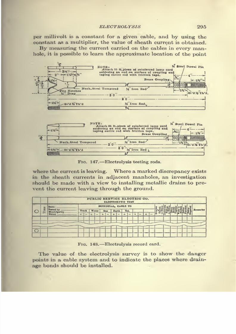
7/28/2019 Underground Trans 00 Me Yeu of t
http://slidepdf.com/reader/full/underground-trans-00-me-yeu-of-t 307/327
ELECTROLYSIS 295
per millivolt is a constant for a given cable, and by using the
constant as a multiplier, the value of sheath current is obtained.
By measuring the current carried on the cables in every man-
hole, it is possible to learn the approximate location of the point
^32
-8H--,-;H
! 1
Attach 15 tt.pieee of reinforced lamp cordsoldering an end on sarface of coupling andtaping entire rod witb friction tape.
H Steel Oowel pia
(«-lH-^,
r.r^
-8 ^OTK yi' Steel Dowel PiaJT Attach 85 It. piece of reinforced lamp cord
soldering an end on surface of coupling andtaping entire rod with friction tape. '^H^l
Brass Coupling
r^^8fd)j'Th'
mH Iron Bod
^
Fig. 147.—Electrolysis testing rods.
where the current is leaving. Where a marked discrepancy exists
in the sheath currents in adjacent manholes, an investigation
should be made with a view to installing metallic drains to pre-
vent the current leaving through the ground.
i
7/28/2019 Underground Trans 00 Me Yeu of t
http://slidepdf.com/reader/full/underground-trans-00-me-yeu-of-t 308/327
CHAPTER X
OPERATION AND MAINTENANCE
Records.—One of the essential things in connection with
the operation of an underground system is the keeping of de-
tailed permanent records. It should be the duty of every cableand underground engineer to keep a system of records which will
enable him to tell at any time the exact amount and the location
of the cable installed.
Suitable forms should be provided to make it an easy matter for
the foreman on the work to make the necessary notes, and these
foremen's reports should be carefully transferred to the perma-
nent office records. A good system of records will be found of
great valuein locating
and taking careof
trouble and in laying outnew work. Such records will also be of assistance to the commer-
cial department in considering new business. It frequently hap-
pens, where complete records are not kept, that the company
depends to a large extent upon the memory of certain employees,
and if these employees leave the company the information is lost.
Diagrammatic layouts of the conduit system and manhole
system are most conveniently kept in loose-leaf or card form.
These records are not drawn to scale, but show a diagram of the
street with a line to represent the conduit, while manholes are
indicated in their proper location by rectangles or other figures
corresponding to the shape of the manhole. Measurements are
indicated, showing distances between centers of covers and also
their location with respect to curb lines. The latter is quite
important, particularly in locations where, during the winter
months, snow covers the ground. Knowing the exact location
of the center of a cover will save considerable time for the cable
men when inspecting manholes on locating trouble. In Fig. 149
is illustrated a system of conduit record, while a manhole record
card is shown in Fig. 150. The number of records necessary will
depend on the size of the company and the nature of the work.
For a comparatively small expense, however, records will be made
which will always be accessible.
296
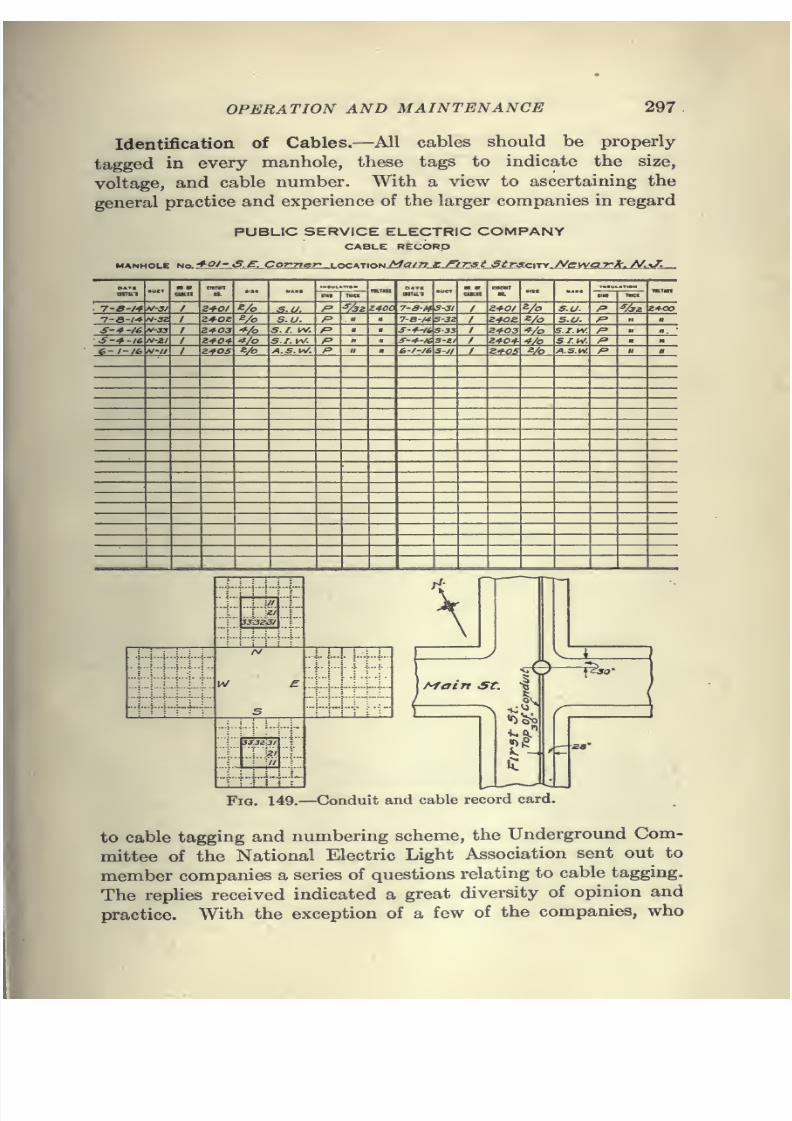
7/28/2019 Underground Trans 00 Me Yeu of t
http://slidepdf.com/reader/full/underground-trans-00-me-yeu-of-t 309/327
OPERATION AND MAINTENANCE 297
Identification of Cables.—All cables should be properly
tagged in every manhole, these tags to indicate the size,
voltage, and cable number. With a view to ascertaining the
general practice and experience of the larger companies in regard
PUBUC SERVICE ELECTRIC COMPANYCABLE RECORD
o*»t
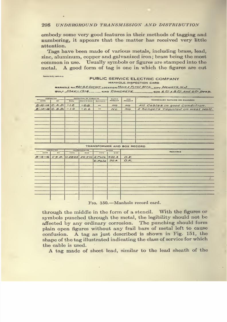
7/28/2019 Underground Trans 00 Me Yeu of t
http://slidepdf.com/reader/full/underground-trans-00-me-yeu-of-t 310/327
298 UNDERGROUND TRANSMISSION AND DISTRIBUTION
embody some very good features in their methods of tagging and
numbering, it appears that the matter has received very little
attention.
Tags have been made of various metals, including brass, lead,
zinc, aluminum, copper and galvanized iron ; brass being the most
common in use. Usually symbols or figures are stamped into the
metal. A good form of tag is one in which the figures are cut
SrKialV'C. IOOO<5-
PUBLIC SERVICE ELECTRIC COMPANYMANHOLE. INSPECTION CARD
MANHOLE No.f.^'/l'S.^Ctorwr.LOCATION i!!?^<.'^[.^^^^
euiLT _j?aSa.li.-.^?y4-__ kind Co/yc-^riEirC ^s\ztJS:^::Jf.SJ^_^rr,djb_^:peep.
m.rioco
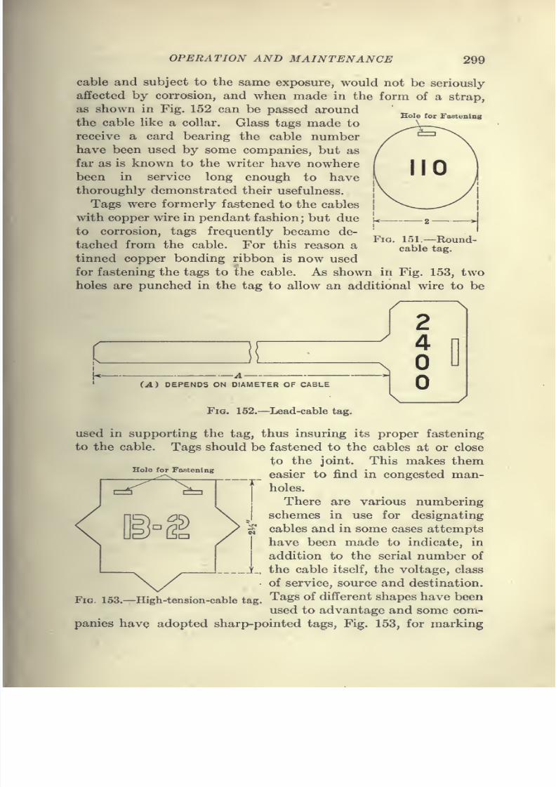
7/28/2019 Underground Trans 00 Me Yeu of t
http://slidepdf.com/reader/full/underground-trans-00-me-yeu-of-t 311/327
OPERATION AND MAINTENANCE 299
Hole for Fastening
cable and subject to the same exposure, would not be seriously
affected by corrosion, and when made in the form of a strap,
as shown in Fig. 152 can be passed aroundthe cable like a collar. Glass tags made to
receive a card bearing the cable number
have been used by some companies, but as
far as is known to the writer have nowhere
been in service long enough to have
thoroughly demonstrated their usefulness.
Tags were formerly fastened to the cables
with copper wire in pendant fashion; but dueto corrosion, tags frequently became de-
tached from the cable. For this reason a
tinned copper bonding ribbon is now used
for fastening the tags to the cable. As shown in Fig. 153, two
holes are punched in the tag to allow an additional wire to be
Fig. 151.—Round-cable tag.
7/28/2019 Underground Trans 00 Me Yeu of t
http://slidepdf.com/reader/full/underground-trans-00-me-yeu-of-t 312/327
300 UNDERGROUND TRANSMISSION AND DISTRIBUTION
high-tension feeders. By choosing different ranges of numbers
for different classes of distribution, distinction can be made as
to the class of service. Letters of the alphabet are sometimes
combined with numerals to show class distinction. The follow-
ing method of numbering is submitted as a simple and ready
means of identification.
Secondary mains, 110-volt numbers 100 to 199 inclusive.
Secondary mains, 220-volt numbers 200 to 299 inclusive.
Primary feeder, single-phase, 2,400-volt. numbers 2,400 to 2,499 inclusive.
Primary feeder, two-phase numbers 4,800 to 4,899 inclusive.
Series-arc circuits numbers 7,500 to 7,599inclusive.
From the foregoing it is noted that a number may be used
which readily indicates the voltage of the circuit. While num-
bering schemes are good, it must be remembered that, as a rule
a given method is applicable only to its particular cable system.
The design and development of any scheme is influenced by so
many local factors that each must be worked out independently'
to suit the requirements. Whether the numbers are placed on
tags or in record books, they must be simple, capable of expansion
without complications, and they should preferably be indicative
to some degree of some function the cable performs.
The use of loose-leaf cable-record books in which duct loca-
tions are given and which can be used as a reference in the field
to check the cable tagging is very desirable. This form of record
has proved highly satisfactory for both field and office use.
In addition to proper tagging some additional safeguard is
usually desirable in ordfer to remove every possibiUty of workmencutting into a live cable. An exploring coil has been used to
advantage in the field to pick up a signal on the desired cable
which has a special signal current impressed upon its conductor
terminals. This same exploring coil and interrupter is also used
in many cases in the field to phase out the conductors of a multi-
ple-conductor cable. Spiking is often resorted to as a last precau-
tion before cutting into a supposedly dead cable, but is not recom-
mendedas
goodpractice, because of its unreliability as it is done
by some cablemen.
In Chapter VI, under the heading "Testing for Live Cable,"
several methods which are considered good practice are described.
Record of Cable and Equipment Failures.—A system of
recording cable failures and subway troubles is of considerable
value. Interruption to service caused by the failure of a cable
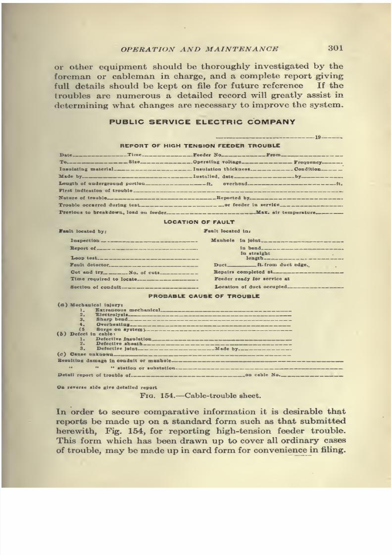
7/28/2019 Underground Trans 00 Me Yeu of t
http://slidepdf.com/reader/full/underground-trans-00-me-yeu-of-t 313/327
OPERATION AND MAINTENANCE 301
or other equipment should be thoroughly investigated by the
foremanor cableman in charge, and a complete report giving
full details should be kept on file for future reference If the
troubles are numerous a detailed record will greatly assist in
determining what changes are necessary to improve the system.
PUBLIC SERVICE ELECTRIC COMPANY
REPORT OF HIGH TENSION FEEDER TROUBLE
Date .Time Feeder No Jrom
To Size Operating voltage Frequency
Insulating materia] Insulation thicltness Condition
Made by Installed, date by
Length o{ underground portion ft. overhead (t.
First indication ot trouble
Nature of trouble Heported by
Trouble occnrred during test. or feeder in service
Previous to breulidown, load ou feeder __Max. air temperature—. _—
LOCATION OF FAULT
Vault located by: Fault located in:
Inspection Manhole In joint
Beport of In bend ,
In straight
Xoop test length .
Fault detector Duct ft. from duct edge..
Out and try. No. of cuts Bepairs completed at ^
Time required to locate Feeder ready for service at
Section of conduit Location of duct occupied _—
.
PROBABLE CAUSE OF TROUBLE
(a) Mechanical injury:
1. Extraneous mechanical
2. 'Electrolysis
3. Sharp bend
4. Overheating
(5 Surge on system)
(&) Defect In cable:
1. Defective insulation
2. Defective sheath
3. Defective joint Made by
(c) Cause unknown
Besulting damage In conduit or manhole
" " " station or substation
Detail report of trouble of on cable No.
On reverse side give detailed report
Fia. 154.—Cable-trouble sheet.
In order to secure comparative information it is desirable that
reports be made up on a standard form such as that submitted
herewith, Fig. 154, for reporting high-tension feeder trouble.
This form which has been drawn up to cover all ordinary cases
of trouble, may be made up in card form for convenience in filing.
7/28/2019 Underground Trans 00 Me Yeu of t
http://slidepdf.com/reader/full/underground-trans-00-me-yeu-of-t 314/327
302 UNDERGROUND TRANSMISSION AND DISTRIBUTION
If this is done, some reduction may be made in the size of the
report. It is
verydesirable,
however, that in entering the in-formation under the headings "Location of Fault" and "Probable
Cause of Injury" the foreman should have the accompanying
form of report at hand and make entries on the form under
one of the several subheadings. The back of the report should
be used for describing previous troubles on the same line or in
the same conduit, which may possibly have had a bearing upon
the fault, as well as other items of interest which cannot be
readily tabulated.
Cleaning Manholes.—Underground systems require much less
attention than overhead lines, but it is a mistake to suppose that
when lines are once underground they will care for themselves.
There is always a chance for trouble. Provision should be made
for cleaning manholes at regular intervals, these cleanings being
sufficiently frequent to prevent insanitary conditions in manholes.
A number of companies maintain portable pumping equipments
which are used by a regular inspection and cleaning division
employed solely in maintaining the underground system in a
satisfactory condition. Before beginning work in manholes
where obnoxious odors or other disagreeable conditions exist,
an effort should be made to supply forced ventilation or adopt
other expedients which will make the conditions in the manhole
tolerable for the workmen. Increasing interest in the welfare
of employees is daily becoming more evident both on the part
of the operating companies and the public authorities having to
deal with such matters. In a large system a considerable saving
in the cleaning of manholes can be affected by a systematic pro-
cedure in the use of large dump wagons and a small gang of men,
who, when work on the cleaning of manholes is slack, join the
various conduit and cable gangs.
Care of Cables.—If a large number of loaded cables pass
through one manhole it is well to take temperature readings
in the manhole to determine when a temperature unsafe for
the cable is reached; these can be taken either with a recording
thermometer or one giving maximum temperature. In cold
weather, or when the streets are muddy, it is sometimes advisable
to have an inspector go over heavily loaded conduit lines to
make sure that the ventilating holes in the manholes covers
are open.
In Fig. 155 are shown curves of manhole temperature, tem-
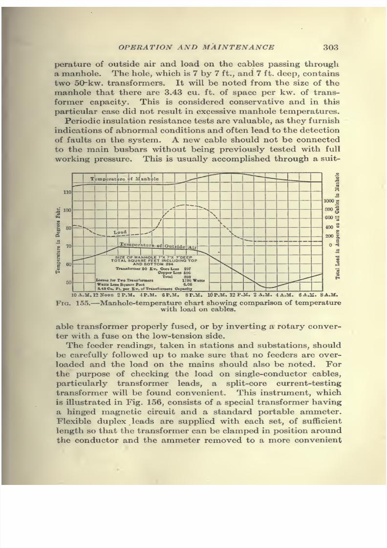
7/28/2019 Underground Trans 00 Me Yeu of t
http://slidepdf.com/reader/full/underground-trans-00-me-yeu-of-t 315/327
OPERATION AND MAINTENANCE 303
perature of outside air and load on the cables passing through
a manhole. The hole, which is 7 by 7 ft., and 7 ft. deep, contains
two 50-kw. transformers. It will be noted from the size of the
manhole that there are 3.43 cu. ft. of space per kw. of trans-
former capacity. This is considered conservative and in this
particular case did not result in excessive manhole temperatures.
Periodic insulation resistance tests are valuable, as they furnish
indications of abnormal conditions and often lead to the detection
of faults on the system. A new cable should not be connected
to the main busbars without being previously tested with full
working pressure. This is usually accomplished through a suit-
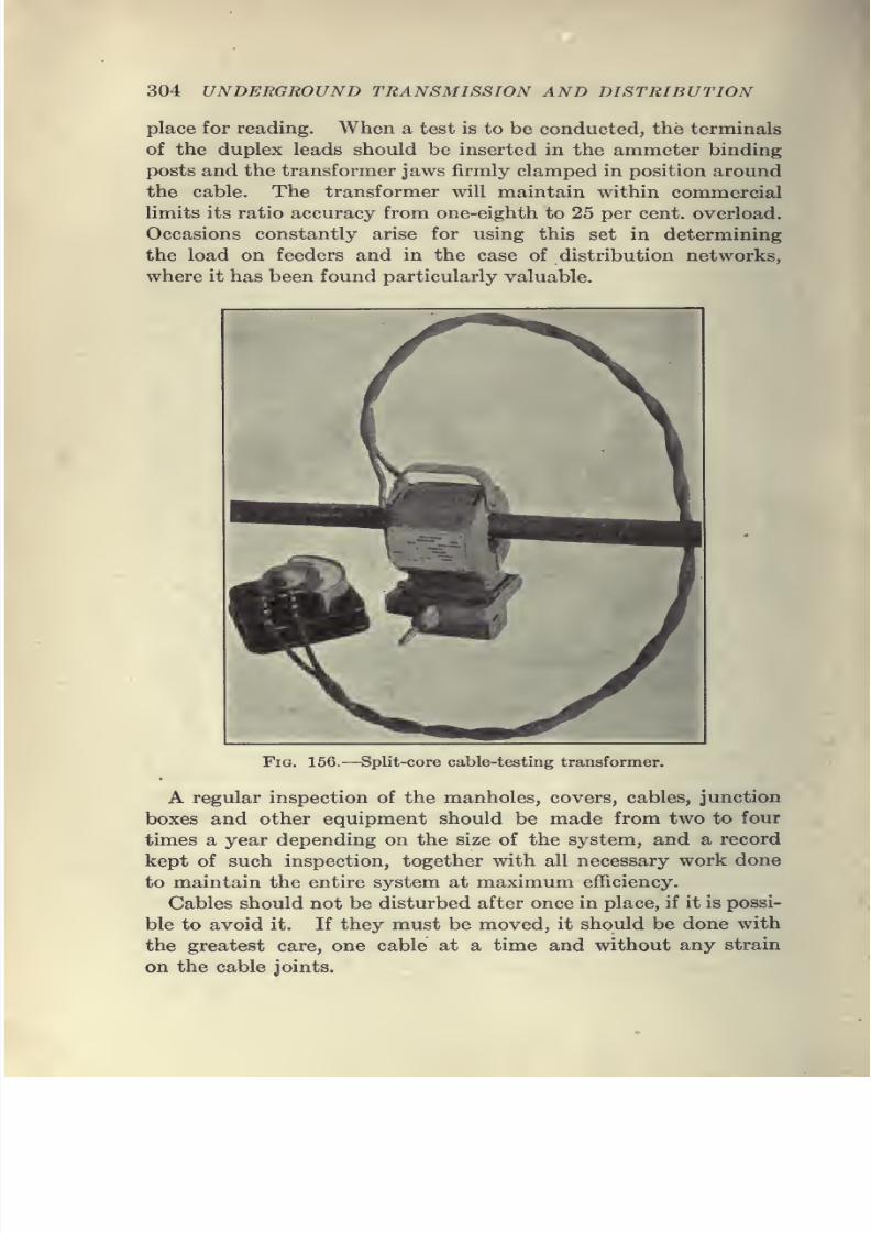
7/28/2019 Underground Trans 00 Me Yeu of t
http://slidepdf.com/reader/full/underground-trans-00-me-yeu-of-t 316/327
304 UNDERGROUND TRANSMISSION AND DISTRIBUTION
place for reading. When a test is to be conducted, the terminals
of the duplex leads should be inserted in the ammeter binding
posts and the transformer jaws firmly clamped in position aroundthe cable. The transformer will maintain within commercial
limits its ratio accuracy from one-eighth to 25 per cent, overload.
Occasions constantly arise for using this set in determining
the load on feeders and in the case of distribution networks,
where it has been found particularly valuable.
Fig. 156.—Split-core cable-testing transformer.
A regular inspection of the manholes, covers, cables, junction
boxes and other equipment should be made from two to four
times a year depending on the size of the system, and a record
kept of such inspection, together with all necessary work done
to maintain the entire system at maximum efficiency.
Cables should not be disturbed after once in place, if it is possi-
ble to avoid it. If they must be moved, it should be done with
the greatest care, one cable at a time and without any strain
on the cable joints.
7/28/2019 Underground Trans 00 Me Yeu of t
http://slidepdf.com/reader/full/underground-trans-00-me-yeu-of-t 317/327
OPERATION AND MAINTENANCE 305
Cables should never be used as steps for entering or leaving
manholes. A small portable ladder should always be used for
this purpose.
It is not possible to estimate accurately the life of cables and
what will be the cost of maintenance after several years' installa-
tion. The cost of repairs for the first year is usually very low
and the other items of maintenance are the expenses for periodic
inspection and testing.
Bonding Cables in Manholes.—The following recommenda-
tions are made by the Underground Committee of the National
Electric Light Association in the matter of the bonding of all
cables in each manhole.
It is of prime importance when faults occur in underground
cables, that the current flowing in the short-circuit should be
sufficient to operate the safety devices or in the absence of safety
devices to make a sufficient disturbance so that the existence of
the trouble will be quickly brought to the attention of the station
operator. In the case of single-conductor cables, whether for
use on Edison three-wire systems having a normal voltage of 115
or 230, or on railway systems having a normal voltage of about 600,
it is entirely possible that a short-circuit may occur between the
conductor and the lead at a point remote from the power supply
station without a sufficient rise in the current to enable the opera-
tor to distinguish it from some unusual load. The lead sheaths
of 1,000,000- and 1,500,000-cm. cables, which are the sizes fre-
quently used, are equivalent to about 70,000 and 80,000 cm. in
copper, respectively, so that if the current which passes throughthe short-circuit from the conductor to the lead is required to tra-
verse only a few blocks of the lead of that particular cable before
it can find other paths to the station, the resistance may be suffi-
cient to limit the current to the normal carrying capacity of the
copper. The radiating surface of the lead is so great that this
large amount of current may be carried for quite an appreciable
time without seriously overheating the lead. The result is that
the arc at the point where the trouble started has in series with it
sufficient resistance so that it burns quite steadily and without
the knowledge of the station operator. This is probably the most
dangerous trouble that can occur on an underground system and
every effort should be made to avoid the occurrence of such a
condition.
The use of concentric cable eliminates the above-mentioned
20
7/28/2019 Underground Trans 00 Me Yeu of t
http://slidepdf.com/reader/full/underground-trans-00-me-yeu-of-t 318/327
306 UNDERGROUND TRANSMISSION AND DISTRIBUTION
difficulty, as an arc of this kind, even if it starts in the outer con-
ductor, is very quickly communicated to the inner, and enough
current will flow in the short-circuit to eliminate any doubt on the
part of the operator as to the nature of the trouble. Where
single-conductor cables are already installed, the condition can
generally be improved by bonding the lead sheaths of all cables
in each manhole. This will, in general give sufficient conductiv-
ity in the return path to cause enough current to flow at the point
of the trouble so that the existence of the trouble is immediately
apparent. The calculations to determine the possible amount
of current that will flow are, however, very simple and should
always be made as a check whenever there is any doubt on this
point.
The bonding of the cables in all manholes also reduces the
liability of damage due to electrolytic action by stray currents of
electric railways, as well as similar damage due to leaky joints
and other troubles on the lighting cables. While there is some
difference of opinion among experts on the subject as to the ex-
act scheme of protection that should be adopted for lead-covered
cables operated by a lighting company, they are in accord on the
proposition that the lead sheaths of all cables be bonded together
in all manholes.
When bonding cables the important feature, necessary for good
results, are a positive low-resistance connection to the lead
sheath and a conducting medium from one cable sheath to the
other. Experience has proved that either copper ribbon or
copper-tinned wire give the best results. A choice between thetwo is simply a matter of opinion and minor manhole require-
ments, the wire having the advantage of a more flexible bond than
the ribbon, when such is an advantage.
Rules and Requirements.—In large systems it is impor-
tant to devise a set of rules for the guidance of the men in the
different departments. These rules must be rigidly complied
with so as to eliminate any danger of injury to men making
tests or repairs to cable or switchboards. While it is impossible
to include in a brief summary complete instructions covering
every detail in connection with underground work, the follow-
ing rules are intended to lay down certain fundamental princi-
ples, which should be observed in all cases. To avoid accidents
to employees or the public, the following rules and cautions are
recommended.
7/28/2019 Underground Trans 00 Me Yeu of t
http://slidepdf.com/reader/full/underground-trans-00-me-yeu-of-t 319/327
OPERATION AND MAINTENANCE 307
Subway Rules
Every splicer, inspector, and helper, must observe the follow-
ing:
Look Out for Gas
Immediately upon opening a manhole or vault and before en-
tering same, make a careful examination for illuminating, sewer,
or other harmful gas. Never enter a manhole where poisonous
gas is found, but report same promptly to foreman or superintend-
ent in charge.
If it is necessary to work in a manhole which does not venti-
late properly after the cover has been removed, an air pump must
be used. A rope must be attached to the body of the workman
in the manhole and fastened above, so that in case of necessity,
he can be drawn to the surface. "Work of this character must be
done only when expressly ordered by the foreman or superinten-
dent and under his direct supervision.
Avoid Explosions
Do not use matches, lamps or candles in or near manholes. If
artificial illumination is required use only incandescent lamps or
approved safety lanterns.
Never carry a gasolene or other furnace or torch into or near
a manhole.
Do not smoke or carry lighted cigars, cigarettes or pipes into
or near a manhole.
Avoid sparks in connecting or disconnecting cables or apparatus
in manholes.
Exercise care in soldering and wiping joints so as not to ignite
the flux.
Watching and Guarding
After removing a cover from a manhole, place around the open-ing the guard provided, to which should be attached a red flag.
When working at night, substitute a red light. Always have a
man at the surface to guard the opening. Replace cover, noting
that it is properly seated, upon completion of work. If excava-
tions are made, see that they are properly fenced, lighted and
guarded.
7/28/2019 Underground Trans 00 Me Yeu of t
http://slidepdf.com/reader/full/underground-trans-00-me-yeu-of-t 320/327
308 UNDERGROUND TRANSMISSION AND DISTRIBUTION
Gloves, Boots, Etc.
When working on any cable or piece of apparatus, wear rubber
gloves and rubber boots, and before beginning work satisfy your-
self that these are in good condition. Do not wear boots with
nails in the heels. Use a dry board to stand on, and an insulating
barrier around live parts where possible. All conducting parts
of tools or appliances that need not be exposed must be insulated.
Be sure your tools are in good condition. Never leave tools lying
around loose where they may come into accidental contact with
live parts. Keep sleeves down and avoid contact between any
part of your body and live cable or apparatus.
Be Sure You Have the Right Cable
When sent out to do any work, be positive you understand
exactly what you are to do. Be sure you have the right cable
before beginning any work. If tags are missing or if from any
cause, there is difficulty in locating the proper cable, report
promptly to the foreman or superintendent.
Live Work
Treat every cable and piece of apparatus as alive until you
have satisfied yourself that it is dead and until then observe all
precautions.
High-voltage Work
Do not work on live high-tension cable or apparatus, without
express and definite orders from the foreman or superintendent.
Never attempt to splice a high-voltage cable alive. When in-
structed to have the current disconnected before beginning work,
make certain that the switchboard attendant understands upon
which circuit you are to work and do not begin until he tells you
the circuit is dead. As soon as you have notified the station
to put the current on, consider the circuit alive. Make certain
that no other workman is engaged on the same circuit before
having current connected.
Report Defects
Report without delay to the foreman or superintendent the
presence of gas or water in manholes, or any defect or unusual
condition you may observe.
7/28/2019 Underground Trans 00 Me Yeu of t
http://slidepdf.com/reader/full/underground-trans-00-me-yeu-of-t 321/327
INDEX
Agreement, form of franchise, 24
Arcing ground suppressor, 276
Armored cable, 94, 129
cables, jointing of, 176
services, 263Arresters, lightning, 216
B
Balanced system of protection, 278
Block distribution, 82
Bond, form of indemnity, 75
Bonds, drainage, 284
Bonding of cables, 305
Boxes, junction, 252
sectionalizing, 252
Brooks system, 6
Built-in system, 7, 88
Bus service, 258
C
Cable pulling grips, 157
reels, 120
systems, operation of, 296
testing equipment, 237
tunnels, 64
Cables, armored, 94, 129
bonding of, 305
current carrying capacity of,
199
diameter and length of, 119, 124
faults in, 233
fibre core, 120general data on, 102-122
heating of, 228
installation of, 151-157
location of faults in, 233
protection of, 195
sector, 126
Cables, specifications, 134, 135, 139-
146
splicing of, 168
split conductor, 278
submarine, 129
tagging of, 297
terminology, 102testing of, 229
transmission, 121
types of, 116
Callender system, 8
Cambric covered cables, 177
Choke coils, 272
Cleaning manholes, 302
Comb, conduit, 45
Concrete, 32
manholes, 62
Conduit installation, 30
Conducell insulators, 187
Conductors, 102-103
Connections to overhead lines, 209
Construction, early forms of, 5
present form of, 17
Contract, form of, 67
Cooling of duct lines, 205
Copper, properties, 104-105
sleeves, 174
Corrosion, electrolytic, 281
Costs, construction, 76
Cost of steel-taped cable, 101
Crompton system, 7
Cumming duct, 13
Current carrying capacity of cables,
199
DDesign of manholes, 54
Development, periods of, 1
Distribution, block, 82
holes, 63
sidewalk, 84
309
7/28/2019 Underground Trans 00 Me Yeu of t
http://slidepdf.com/reader/full/underground-trans-00-me-yeu-of-t 322/327
7/28/2019 Underground Trans 00 Me Yeu of t
http://slidepdf.com/reader/full/underground-trans-00-me-yeu-of-t 323/327
INDEX 311
Manholes, cleaning of, 302
concrete, 62
construction of, 46
cost of, 79
design of, 54
distribution, 54
heating of, 302
in quicksand, 49
transformer, 55
transmission, 54
types of, 48
ventilation of, 225, 250
Maps of conduit systems, 19
Materials, selection of, 30
Merz system of cable protection,
278
Meter protection, 263
Mica tube joints, 186
Moisture in cable insulation, 149
Multiple tile duct, 34
Municipal regulation, 23-27
N
Network protector, 261
Neutral, grounding of, 277
O
Obstructions, 20
Oils, impregnating. 111
Operation of cables, 125
of cable systems, 296-302
Paper cables, jointing of, 177
cable specifications, 139
insulation, 111
tube joints, 179
Periodic testing of cables, 240
Permits, 21
Pipe forcing jack, 91
Plans for conduit construction,
19
Pole terminals, 209
Potheads, 209
Power trucks, 164
Present forms of construction, 17
Protecting sheaths against electrol-
ysis, 287
Protection of cables, 195
of transmission systems, 270
Protective pipe coatings, 285
Protector on A. C. networks, 261
R
Rating of cables, 199
Reactance coils, 272
Records of cable failures, 300
installations, 296
Reels, cable, 120
Reel jack, 151
Regulations, mvmicipal, 23-27
Relays, 270
Repairing cable failures, 233
Right-of-way, 22
Rodding ducts, 154
Rope for pulling cables, 160
Routing of duct lines, 86
Rubber cable specifications, 135covered cable, jointing of, 176
insulation, 109
Rules, safety, 306
standardization, 228
S
Safety devices, 217
regulations, 306
Sealing of ducts, 47
Secondary mains, 246
Sectionalizing boxes, 252
Sector cables, 126, 278
Selective fault localizer, 274
Service bus, 258
connections, 90
Services, protection of, 263
Sheath, lead, 114
Sheaves for cable pulling, 164
Sidewalk distribution, 84
Single tile duct, 34
Slack in cables, 167
Sleeve-filling material, 183
Sleeves, copper, 174
lead, 173
Solid system, 88
7/28/2019 Underground Trans 00 Me Yeu of t
http://slidepdf.com/reader/full/underground-trans-00-me-yeu-of-t 324/327
312 INDEX
Specifications, cable, 134, 135, 139-
146
conduit and manhole, 67
Splicing cables, 168
equipment, 217
Split conductor cables, 278
core transformer, 303
Standardization rules, 228
Steel-pipe systems, 14
taped cable, 94-100
cost of, 101
Stone duct, 40
Street distribution, 81
lighting cable, 97
Submarine cables, 129
Subway transformers, 248
Suppressor, arcing ground, 276
Surveys, electrolysis, 293
Switches, oil, 259
manhole, 259
Tagging of cables, 297
Temperature of cables, 228
Terminal blocks, 97
Terminals, pole^ 209
Terminology, cable, 102
Test holes, 20
voltages, 123
Tests, high voltage, 240>periodic, 240
Testing equipment, 237
of cables, 229
for live cables, 223
Tile duct, 34
Tools for splicing, 217
Transformer manholes, 55
split core, 303
Transformers, underground, 248
Transmission cables, 121
systems, protection of, 270
Trucks, power, 164
Tunnels, cable, 64
U
Underground transformers, 248
Units, electrical, 227
Vacuum joints, 188
Varnished cambric, 113
Ventilation of manholes, 225, 250
Voltages, wroking and test, 123
W
Waterproofing manholes, 54
Webber system, 13
Winch, cable puUing, 161
Wooden dtict, 14
Wrought iron pipe systems, 14

7/28/2019 Underground Trans 00 Me Yeu of t
http://slidepdf.com/reader/full/underground-trans-00-me-yeu-of-t 325/327
•^

7/28/2019 Underground Trans 00 Me Yeu of t
http://slidepdf.com/reader/full/underground-trans-00-me-yeu-of-t 326/327
7/28/2019 Underground Trans 00 Me Yeu of t
http://slidepdf.com/reader/full/underground-trans-00-me-yeu-of-t 327/327