unified communication & desktop video collaboration
TRANSCRIPT

National Aeronautics and Space Administration
www.nasa.gov
Model-Based Engine Control
Joe Connolly Amy Chicatelli & Sanjay Garg
3rd GRC PCD Workshop Feb. 28 – Mar. 1, 2012, Cleveland, OH
1

National Aeronautics and Space Administration
www.nasa.gov
Outline
• Overview
• Motivation • Approach
• Results
• Conclusions and Future Work
2

National Aeronautics and Space Administration
www.nasa.gov
Model-Based Control and Diagnostics
Ground Level
Engine Instrumentation • Pressures • Fuel flow • Temperatures • Rotor Speeds
Actuator Commands • Fuel Flow • Variable Geometry • Bleeds
Ground-Based Diagnostics • Fault Codes • Maintenance/Inspection Advisories
Validated Sensors
On-Board
Fault Detection and Isolation
Logic
Performance Estimates
Sensor Estimates
Sensor Measurements
Actuator Positions
“Personalized” Engine Control
On-Board Model & Tracking Filter
• Efficiencies • Flow capacities • Stability margin • Thrust
• Real-time performance estimation • Enhanced gas path diagnostics • Performance enhancing engine control

National Aeronautics and Space Administration
www.nasa.gov
MBEC Overview • Subsonic Fixed Wing (SFW) / Efficient Propulsion and
Power (EPP) Sub-project Objective: – Create, advance, and validate technologies and engine component
performance prediction tools that will reduce thrust specific energy consumption and contribute to the performance metric's of N+3 vehicle concepts
• Model-Based Engine Control (MBEC) helps achieve this objective by developing controls logic technology to allow more efficient operation of the engine with a tighter control of stability margins – MBEC Objective: Develop an on-board model based engine
control architecture and demonstration simulation for a commercial aircraft engine that provides reduced specific fuel consumption while maintaining safe operation throughout the engine life
4

National Aeronautics and Space Administration
www.nasa.gov
• Thrust cannot be measured and hence is indirectly controlled through regulating a measured variable which correlates with thrust – Fan Speed, Engine Pressure Ratio (EPR)
• Throttle to Thrust relationship changes over engine life • Surge Margins cannot be measured. Safe margins are indirectly maintained by the accel and decel limits
• Conservatism provided in selecting a “nominal” operating line to maintain safe margins throughout engine life
Typical Current Engine Control
5

National Aeronautics and Space Administration
www.nasa.gov
MBEC Motivation • The goal is to use an on-board “adaptive” model of the
engine to provide accurate estimates of unmeasured parameters that are used in the control system design – MBEC will enable operation of an engine with less conservative
safety margins, since all safety margins currently are designed to an end of life engine, whereas an on-board model can provide a more accurate margin estimate for the actual condition of the flight engine
• The longer-term pay-off is to have a “personalized” control for each engine, which adapts to the condition of the engine to not only maintain the most efficient operation throughout its lifetime, but also increase the useful operating life. – MBEC will enable consistent PLA to thrust performance for the
entire engine life cycle and possibly improve engine life expectancy by using an accurate estimate of thrust as a direct feedback variable for control through an on-board model
6

National Aeronautics and Space Administration
www.nasa.gov
MBEC What’s New? • MBEC Concept has been around since early 1990s
– The challenge has been to “adapt” an on-board model to the engine condition so as to get “accurate” enough estimates of “unmeasured” quantities of interest
• The “Optimal Tuner” based performance and condition estimation technique provides an innovative solution to this challenge – Simulation studies have shown that Thrust, Hot Section
Temperatures, and LPC/HPC Surge Margins can be “accurately” estimated even with engine degradation with usage
7
National Aeronautics and Space Administration
www.nasa.gov
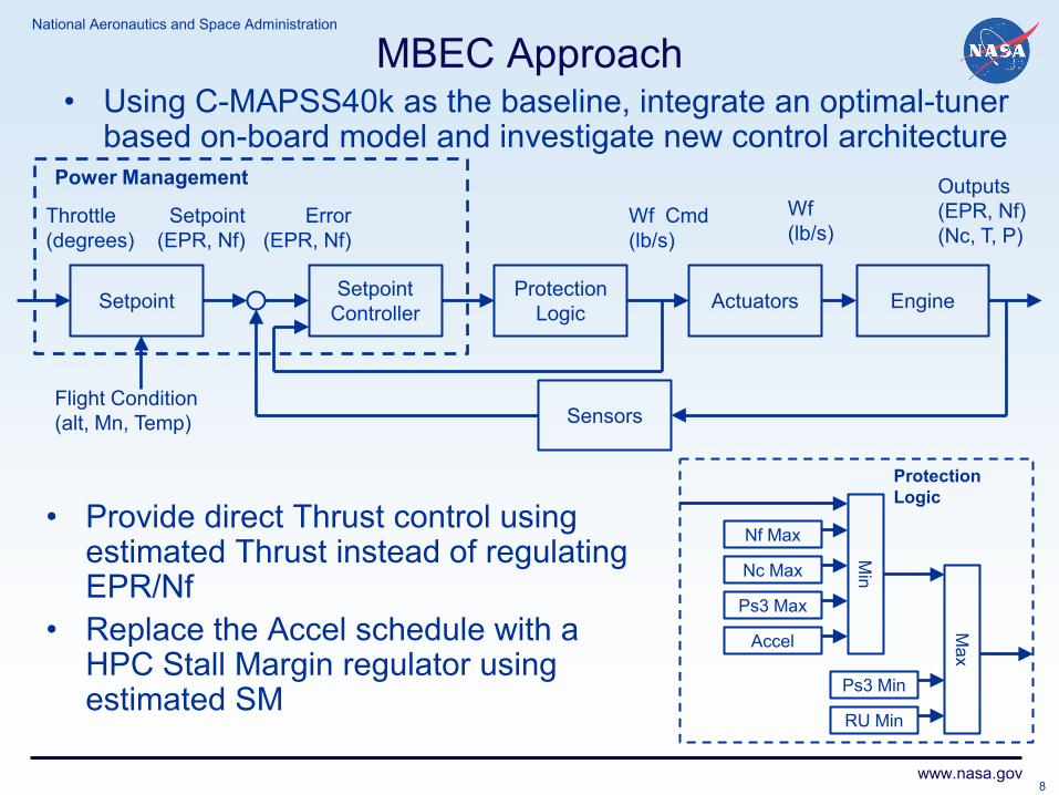
MBEC Approach • Using C-MAPSS40k as the baseline, integrate an optimal-tuner
based on-board model and investigate new control architecture
Throttle (degrees)
Setpoint (EPR, Nf)
Error (EPR, Nf)
Wf (lb/s)
Outputs (EPR, Nf) (Nc, T, P)
Power Management
Setpoint Controller
Wf Cmd (lb/s)
Flight Condition (alt, Mn, Temp)
Actuators Engine Protection Logic
Sensors
Setpoint
Nf Max
Nc Max
Ps3 Max
Accel
Ps3 Min
RU Min
Min
Max
Protection Logic
• Provide direct Thrust control using estimated Thrust instead of regulating EPR/Nf
• Replace the Accel schedule with a HPC Stall Margin regulator using estimated SM
8

National Aeronautics and Space Administration
www.nasa.gov
SFW – EEP – MBEC Phased Approach
• Phase I: Linear Operating Point Control Design • Implement Optimal-tuner based model and evaluate estimation
accuracy for parameters of interest • Implement direct thrust control and investigate benefits • Implement HPC SM regulator and evaluate accuracy • In a pseudo-linear environment, investigate the capability to maintain
desired min SM with the accel schedule replaced by HPC SM regulator
• Phase II: Nonlinear Control Design • Develop the model-based control architecture over the whole operating
envelope • Investigate performance benefits while maintaining safety throughout
the engine operating life
• Phase III: Investigate potential benefits of using MIMO Model-Based Control
9

National Aeronautics and Space Administration
www.nasa.gov
Verification of the Optimal Tuner Estimation
• The C-MAPSS40k linear engine model is used as the truth model for the MBEC simulation and will subsequently be referred to as the engine
– The goal here is to illustrate that the estimation scheme will accurately model the engine thrust as shown in the plot.
Command Controller Engine Estimation Error
Thrust
Disturbance/ Health
External Inputs
Safety Margins
Fan Speed/Engine Pressure Ratio
Limiting Parameters
10

National Aeronautics and Space Administration
www.nasa.gov
MBEC Direct Thrust Control • A MBEC simulation is developed by integrating the continuous
time optimal tuner, thrust controller, and a linear operating point C-MAPSS40k model
Thrust Command Controller Engine
Optimal Tuner Kalman Estimation
Error
Est. Thrust
Disturbance/ Health
External Inputs
Surge Margin
Estimated Thrust
Limiting Parameters
True Thrust
Thrust variation with EPR Control Tight Thrust response with MBEC
11

National Aeronautics and Space Administration
www.nasa.gov
Surge Margin Estimation Analysis • Ability of the Optimal-tuner based model to accurately
estimate the HPC SM was analyzed. • The transient accuracy of the estimation is illustrated for a
2o PLA change with a 50% deteriorated engine
• The SM estimation accuracy is not sufficient for direct SM regulation – The optimal-tuners were
selected to minimize Thrust errors
• Need to redefine the cost function for optimal-tuner selection to include minimization of SM estimation error
12

National Aeronautics and Space Administration
www.nasa.gov
Analysis with Modified Optimal Tuners • With Optimal-tuner selection modified to include SM
estimation error in the cost function, a more accurate transient estimate of SM is obtained.
13

National Aeronautics and Space Administration
www.nasa.gov
MBEC Next Step • Implement a pseudo-linear implementation of accel
schedule and compare performance with MBEC implementation of min HPC SM regulator.
14

National Aeronautics and Space Administration
www.nasa.gov
Conclusions and Future Work • The demonstrated MBEC architecture using a linear C-MAPSS40k
engine model and a continuous time optimal filter has been shown to provide a tight thrust control given various engine deterioration levels
• The ability to provide direct control of thrust should provide improved on-wing engine life
• Investigation of the HPC SM estimation demonstrated that the Optimal-tuner selection has to be done with the cost function to be minimized reflecting the desired estimation objectives
• Current approach is to complete the linear model investigations by mid June 2012, and move on to nonlinear MBEC implementation on C-MAPSS40k
15