unified physical infrastructure solutions for industrial
TRANSCRIPT

May 2011 • WP-14 Unified Physical InfrastructureSM Solutions for Industrial Automation Optimizing Control Panel Layouts for Noise Mitigation in Factory Automation Systems Authors: Dan McGrath, Solutions Manager Michael Berg, Product Manager
White Paper

W©2
O
Th
ha
in
pr
(V
El
fa
de
bo
in
pa
El
co
ar
wi
in
sy
m
Pa
so
be
re
th
Ta
WW-CPWP-14, R2010 Panduit Co
ne of the core iss
he electrical nois
ard switched indu
terfering with ana
rograms. The pro
VFDs) and servo
lectrical noise (1
ault state; (3) can
elays. These pro
onding, and inad
advertently introd
anel layout pract
lectromagnetic in
omponents and p
re rising with incr
ithout any though
terference (RFI).
ystem and cause
aintainable infras
anduit’s Unified P
olutions that addr
enefits of this app
esult, this white p
e industrial auto
able 1. Risk to In
Noise Sources • Servo drives • VFD drives • Switching pow• Contact switch
loads (contactsolenoid valve
• ESD • Lightning
NoisSourc
ev.1, 05/2011 orp. All rights res
sues affecting th
se emitted from s
uctive loads (rela
alog signals, Ind
oliferation of high
motion systems
) causes field de
cause equipme
blems can be am
equate segregat
ducing productiv
ices that create e
nterference (EMI
power devices w
reasing materials
ht to the deleterio
. These problem
e industrial Ethern
structure (see Ta
Physical Infrastru
ress core busine
proach include ri
paper demonstrat
mation environm
Industrial Autom
wer supplies hing of inductive tor coils, es)
se ces
erved.
he performance a
sources such as
ays/contactors) c
ustrial Ethernet t
h speed switching
is also introduci
evices to misread
nt damage; (4) re
mplified by poor c
tion of noise sou
vity, quality, and e
electrical noise p
) risks increase a
hile also attempt
s costs. Too often
ous effects of po
s can disrupt com
net installations t
able 1).
uctureSM (UPI) ap
ess systems – po
isk mitigation, low
tes best practice
ment.
mation Systems
Noise Victims• Communica
wiring • Analog sign• High speed • Controllers• Microproces
devices, drivsensors
• Electronic e• Protective d
NV
for Noi
and reliability of i
Pulse Width Mod
can adversely aff
transmissions, a
g power systems
ng more noise in
d the environmen
esults in signal re
control panel layo
rces from suscep
even safety risks
problems.
as a result of com
ting to minimize p
n, Ethernet switc
oor cable bend ra
mmunications an
to not deliver on
pproach is found
ower, control, com
wer costs, increa
es for mitigating p
s Due to EMI No
s ations/network
nal wiring counting signals
ssor based ves, computers,
equipment devices
Noise Victims
Oise Mitigation
ndustrial control
dulation (PWM) d
fect system effici
nd programmabl
s found in today’s
nto industrial sys
nt; (2) causes dev
etransmission th
out practices or d
ptible devices. D
s by following obs
mpeting needs to
panel footprint to
ches are stuffed i
adius and exposu
nd control functio
their promise of
ed on best pract
mmunication, com
ased agility, and
performance issu
ise
s
Business R• Productiv• Downtime• Maintena• Troublesh• Device re• Inability to
demands
Optimizing Con in Factory Au
systems is elect
drives, power su
ency and uptime
le logic controller
s Variable Frequ
tems.
vices to fail, rese
hat can inflict com
deficient groundi
esigners may be
solete or misguid
o pack in more n
o reduce panel co
into existing pan
ure to EMI or rad
ons of the entire a
robust, reliable a
tices to deploy ph
mpute, and secu
enhanced sustai
ues due to electri
Risks vity Loss e nce/repair costs hooting costs eplacement costso respond to mar
Business Risks
2
ntrol Panel Lautomation Sy
trical noise.
pplies, and
e by
r (PLC)
ency Drives
et, or enter a
mmunication
ing and
e
ded control
etworked
osts, which
el designs
diofrequency
automation
and
hysical layer
urity. The
inability. As a
ical noise in
s rket
ayouts ystems

WW-CPWP-14, Rev.1, 05/2011 ©2010 Panduit Corp. All rights reserved.
3
Optimizing Control Panel Layouts for Noise Mitigation in Factory Automation Systems
These best practices include: (1) system design of Ethernet channel with increased margin over standards and
noise immunity; (2) high frequency bonding; (3) use of flat braided straps; (4) proper segregation and spacing of
“clean” and “noisy” circuits; and (5) grounding of shielded cabling. This paper also describes how optimizing the
control panel layout can increase the efficiency of the control environment and further mitigate the impact of
noise emissions in industrial networking applications.
Converged Industrial Systems Can Be at Risk from Electrical Noise A fresh look at approaches to control panel layout can result in improved reliability and performance along with
optimized usage of panel space. Three key strategies greatly improve control panel design:
1. Follow a multi-layered electrical noise prevention and mitigation strategy that optimizes control panel
space utilization. Different layers should include grounding/bonding, separation, shielding, and
filtering practices to provide optimal protection.
2. Implement an Ethernet layer leveraging TIA/EIA best practices yet protected from industrial risks (i.e.,
shock and vibration, extreme temperature, chemical exposure). These practices include panel space
and cable management and media and connectivity selection.
3. Leverage templates such as reference design and panel layout design tools to minimize engineering
time, mistakes, and drive consistency.
A small investment in time spent up front creating improved designs can save many hours of time during
installation, commissioning, and subsequent troubleshooting/maintenance during the operational lifetime of the
system.
Types of Electrical Noise Electrical noise is a very real threat to reliable, productive processing or manufacturing operations (see Figure
1). Several types of electrical noise can occur, and each requires solutions to mitigate or eliminate the problem.
The types of noise differ in their frequency range and how the offending signals attach themselves to victims.
Types of electrical noise interference include:
• “Low” frequency 50-60 Hz interference
• “High” Frequency noise from 100 KHz – 30 MHz
• Radiated frequency interference (100 MHz and above)
• Electrostatic Discharge (ESD)
Types of problems resulting from electrical noise:
• Erratic operation of sensing systems where measurements may be disrupted or have false variability
• Unstable production measurements such as miscounts or corruption of output sensors
• Controller lockups or memory corruption as with PLC or PAC system lockups
• Component failure over time such as when input circuits or protective devices are hit too many times
with spikes
• Communication failures with transmit/receive causing dropouts, retries, and missed packets
All these types of electrical noise (both EMI and RFI) take the form of an external electromagnetic signal
interfering with the normal, desired signal or control action that is expected to occur. EMI is not a problem in
itself, unless it is transferred into a victim circuit through one of the possible coupling means.

WW-CPWP-14, Rev.1, 05/2011 ©2010 Panduit Corp. All rights reserved.
4
Optimizing Control Panel Layouts for Noise Mitigation in Factory Automation Systems
Figure 1. The above shows the potential for EMI coupling between noise generating motor drive cabling and noise sensitive cabling, such as communications cabling (e.g. Ethernet), analog signal transmission or other signal cabling within an industrial control panel.
Noise Coupling Means and Mitigation Strategies There are three primary means for noise coupling that can occur in control panels that can be mitigated if the
underlying factors are identified and understood (see Table 2).
Table 2. Noise Coupling Means and Mitigation Strategies.
Coupling Means Factors Mitigation • Inductive or magnetic coupling
(Current in the noise source producing a field that causes a corresponding current in the victim conductor)
• Loop size • Orientation • Distance • Rate of change • Current amplitude
• Route DC supply and return together rather than in separate runs.
• Separate noise sources from noise victims by 8” or more.
• Cross noise sources and victims at right angles
• Magnetic shielding (highly conductive material) with both ends of cable terminated
• Capacitive or electrostatic coupling (Voltage spike in the noise source causes voltage to develop in the victim conductor)
• Voltage amplitude, rate of change of source
• Victim impedance • Conductor spacing • Geometry, orientation
• Separation • Electrostatic shielding (conductive
material) with at least one end bonded
• Common mode conductor (Victim circuit shares common conductor such as a current return path with a noise source current return)
• Wiring layout • Daisy chaining • Bonding design
• Separate return path from noise • Star bonding to ground • Separate commons back to source

WW-CPWP-14, Rev.1, 05/2011 ©2010 Panduit Corp. All rights reserved.
5
Optimizing Control Panel Layouts for Noise Mitigation in Factory Automation Systems
Multi-Layered Approach to Noise Mitigation The National Security Agency first developed the concept of Defense in Depth (DiD) as a tactical approach to
information and electronic security. The same basic layering concept used in defending against a security threat
can also apply to defending against the threat of EMI on critical communications and controls infrastructure. The
following section describes the layers involved: inner layers are focused on preventing noise problems through
proper bonding/grounding and segregation/ separation practices, and outer layers address mitigation of existing
noise sources through shielding and filtering/suppression.
Grounding and Bonding Grounding and bonding is the foundation for controlling EMI in control systems. Because grounding is an NEC
requirement for electrical safety, the sight of green and yellow ground straps, ground bars, and PE conductors
are common and relatively well understood.
However, a grounding system can be fully compliant and yet have equipment that encounters serious
disruptions, stoppages, even damage due to an inadequately installed and engineered low impedance
ground/bonding system for high frequency noise. Three concepts of best practice control panel layout and
design for this high frequency noise are:
1. Apply a proper ground plane
To have effective noise mitigation a ground plane needs to be employed inside the control panel to reduce the risk of current loops or devices inadequately grounded inside the control panel. This technique is similar to what is used in printed circuit board designs where all the circuits are referenced to a common potential or ground plane. By following the steps listed below, noisy devices such as motor drives and power supplies will be properly coupled to ground which will greatly reduce their EMI and RFI emissions. Follow through with this method to connect ancillary equipment, remote devices or auxiliary panels to be connected to the same common ground to further reduce the machine’s EMI/RFI emissions. A design with multiple grounds is an invitation for noise problems. To maximize the ground plane effectiveness, remember it is important to keep the wiring being routed close to the ground plane (back panel).
2. Deploy effective high frequency return path(s)
High frequency noise currents will return to their source to complete a circuit. In some cases this can lead to noise being coupled into adjacent Ethernet cables. The goal is to lay out noise sources and cabling with their associated grounds and cable shields so that the noise currents return in a safe controlled path rather than inadvertently travelling through sensitive circuit cables and devices. This requires understanding the noise sources and the role of shielded cables and equipment grounds.
Tips for Installing a Proper Ground Plane
• Use an electro galvanized sub-panel instead of the more common painted panel. This avoids need to remove paint for bonding with resultant long term corrosion potential risking poor performance.
• Bond the incoming ground conductors to the sub-panel where they enter the panel (for example, to a ground bar such as the Panduit Universal Ground Bar, see Figure 2).
• Bond multiple sub-panels together using 1” wide short flat braided bonding straps to create one large ground plane (see Figure 3).
• Bond the equipment grounds from the components in the cabinets directly to the sub-panel using equipment manufacturer recommended conductors or short flat braided bonding straps.
• Bond the enclosure door(s) with short flat braided bonding straps.
• Bond incoming cable shields, conduits, and cable trays to back panel of the enclosure
Figure 2. The Panduit® StructuredGround™ Universal Ground Bar System facilitates bonding incoming conductors as well as supplemental bonding between panels for noise mitigation.
WW-CPWP-14, Rev.1, 05/2011 ©2010 Panduit Corp. All rights reserved.
6
Optimizing Control Panel Layouts for Noise Mitigation in Factory Automation Systems
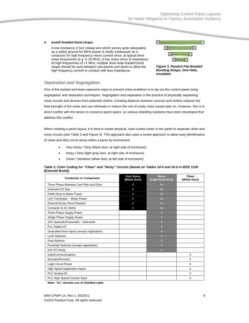
3. Install braided bond straps
A low resistance 3 foot 14awg wire which serves quite adequately as a safety ground for 60Hz power is totally inadequate as a conductor for high frequency return current since, at typical drive noise frequencies (e.g. 5-10 MHz), it has many ohms of impedance. At high frequencies of >1 MHz, multiple short wide braided bond straps should be used between sub-panels and doors to allow the high frequency current to conduct with less impedance.
Separation and Segregation One of the easiest and least expensive ways to prevent noise problems is to lay out the control panel using
segregation and separation techniques. Segregation and separation is the practice of physically separating
noisy circuits and devices from potential victims. Creating distance between sources and victims reduces the
field strength of the noise and can eliminate or reduce the risk of costly noise issues later on. However, this is in
direct conflict with the desire to conserve panel space, so various shielding solutions have been developed that
address this conflict.
When creating a panel layout, it is best to create physical, color-coded zones in the panel to separate clean and
noisy circuits (see Table 3 and Figure 4). This approach also uses a zoned approach to allow easy identification
of clean and dirty circuit areas within a panel by technicians:
• Very Noisy / Dirty (black duct, at right side of enclosure)
• Noisy / Dirty (light gray duct, at right side of enclosure)
• Clean / Sensitive (white duct, at left side of enclosure)
Table 3. Color Coding for “Clean” and “Noisy” Circuits (based on Tables 10-4 and 10-5 in IEEE 1100 [Emerald Book])
Conductor or Component Very Noisy (Black Duct)
Noisy (Light Gray Duct)
Clean (White Duct)
Three Phase Between Line Filter and Drive X Xs Extended DC Bus X Xs PWM Drive to Motor Power X Xs Line Terminator – Motor Power X Xs External Dump Shunt Resistor X Xs Contactor to AC Motor X Xs Three Phase Supply Power X Single Phase Supply Power X 24V Hydraulic/Pneumatic – Solenoids X PLC Digital I/O X Dedicated Drive Inputs (except registration) X Limit Switches X Push Buttons X Proximity Switches (except registration) X 24V DC Relay X Data/Communications X Encoder/Resolver X Logic Circuit Power X High Speed registration Inputs X PLC Analog I/O X PLC High Speed Counter Input X Note: “Xs” denotes use of shielded cable
Figure 3. Panduit Flat Braided Bonding Straps, One-Hole, Insulated.

WW-CPWP-14, Rev.1, 05/2011 ©2010 Panduit Corp. All rights reserved.
7
Optimizing Control Panel Layouts for Noise Mitigation in Factory Automation Systems
In addition, it is good practice to follow applicable codes for separating various voltage classes by providing
separate wiring duct to avoid mixing high and low voltage cabling. Higher voltage devices should be mounted in
the upper right-hand corner of the panel, keeping as much distance as possible from other electronic devices
(such as PLCs, DC power supplies, and timers) positioned on the opposite left side of the panel. Also maintain
distance between motor power and encoder, I/O, and analog cables.
Figure 4. Reference Layouts for Circuit Separation to Mitigate Noise in Control Panels (Figures 10-10 and 10-11 in IEEE 1100 Emerald Book)

WW-CPWP-14, Rev.1, 05/2011 ©2010 Panduit Corp. All rights reserved.
8
Optimizing Control Panel Layouts for Noise Mitigation in Factory Automation Systems
Separation Distances Past standard IEEE 518 (withdrawn in 2002) provided some guidance on the minimum distances between
certain types of conductors in parallel runs based on noise susceptibility / generation. However, the evolution of
power and signal wiring requires an update to this approach. ISO/IEC 24702, Generic Cabling for Industrial
Premises, recommends the M.I.C.E. (Mechanical, Ingress, Chemical, and EMI) classification to help designers
select proper cabling. Rather than defining separation distances, MICE defines the environmental conditions,
including noise, where cabling will be installed. Proper cabling type is selected based on environmental class.
As noise coupling will drop off with the square of the distance of separation, moderate separation distances
between wiring classes provide effective noise mitigation. A separation
distance of 3-6 in. (75-150 mm) is recommended between high noise and
low noise circuits. A minimum of 12 in. (300 mm) separation should be
maintained between encoder or resolver feedback cables and the motor
cables or any AC power cables. This is more critical with resolver cables
due to the analog nature of the signals.
Barriers and Partitions When physical separation cannot be fully maintained, a conductive
physical barrier or partition can be used to effectively provide wire
segregation and shielding while reducing physical separation distance
between wires. A metal barrier provides the greatest shielding protection
from magnetic and capacitive coupled noise (see Figure 5).
A metal barrier is capable of providing 20dB reduction in noise which is
equivalent to up to 6 inches of air spacing (see Figure 6). The value in
reducing or eliminating the air spacing between the cables is to provide
more optimal use of space within the enclosure. A noise barrier can also
be used to enhance other noise mitigation efforts, including air spacing,
for a defense in depth approach and a more robust controls system
design.
Shielded Wire Ways (Trunking) Another method to provide wire segregation and shielding while reducing
physical separation distance between wires is to use a shielded wire way
or shielded trunking. This method is similar to a metal barrier but also
provides a channel for routing larger wire counts and is fully enclosed for
greater protection. A shielded wire way also is capable of providing a
20dB reduction in noise which is equivalent to up to 6 inches of air
spacing (see Figure 6). As with metal barriers the value in reducing or
eliminating the air spacing between the cables is to provide more optimal
use of space within the enclosure. A shielded wire way can also be used to
enhance other noise mitigation efforts, including air spacing, for a defense
in depth approach and a more robust controls system design.
Figure 5. A metal barrier such as Panduit’s PanelMax™ Noise Shield.
Figure 6. A metal noise barrier or shielded wire way can provide noise mitigation and free up space in the enclosure.

WW-CPWP-14, Rev.1, 05/2011 ©2010 Panduit Corp. All rights reserved.
9
Optimizing Control Panel Layouts for Noise Mitigation in Factory Automation Systems
Some products, such as Panduit® PanelMax™ Shielded Wiring Duct,
have wire openings similar to conventional wiring ducts to provide
both wire management capability and shielding (see Figure 7). The
shielded wiring duct features a continuous metal exterior that
connects the duct base to the ground plane (e.g. galvanized back
panel) and provides protection from inductive and capacitive coupled
noise over the height of either sidewall.
In the example panel shown in Figure 8, a Panduit noise barrier and
shielded wiring duct have been installed between the noisy cabling
pathway connecting VFD motor drives and other clean control cable
pathways within an enclosure. The shielded wiring duct and noise
barrier shown maintain the equivalent noise reduction as if air spacing was present and requires less space in
the panel width compared with a conventional layout. In the 72 inch x 72 inch x 24 inch stainless steel enclosure
savings could be as high as 8 cubic feet of the enclosure volume. Considering costs of greater than $150 per
cubic foot for a stainless steel enclosure, utilizing a noise barrier can prove an effective method to implement
noise mitigation techniques without incurring excessive material costs.
Selection Criteria for Barriers, Partitions, and Shielded Wire Ways Selection criteria for a barrier or shielded wire way should include its material for relative conductivity and
corrosion resistance and preferably will have performance data indicating its capability for EMI noise reduction.
The standard for performance is a barrier made from copper. However in application a corrosion resistant steel
barrier provides good performance while also being economical and durable. Note that non-metallic (i.e. PVC)
divider partitions commonly used within wiring duct channels are similar in form to a noise barrier yet offer no
protection against electrical noise. These dividers are intended for separation and increasing wire insulating
factors but will provide no noise reduction or protection.
Shielding performance is also strongly linked to proper installation to achieve a low impedance (resistance) path
to the sub-panel as part of the ground plane (see Figure 9). Installation screws alone cannot create this low
impedance path; to be effective a substantial area of metal to metal contact to the sub-panel must be made at
each end of the barrier. Use of conductive galvanized sub-panels aids in making an electrical connection easily
and reliably, versus painted panels which require paint removal for metal contact. To ensure the low impedance
path is maintained, bare metal surfaces should also be protected at the connection point with an anti-oxidizing
paste that does not affect conductivity.
Small perforations or holes also may be present in a barrier or shielded wire way without substantially
degrading performance against coupled noise in frequencies up to 30 MHz. Although this technique may seem
counterintuitive, these small holes can be useful for attaching cable ties for wire management or providing a
pass through slot for conductors. Care should be taken in selection to use only barriers or barrier materials with
smooth burr free edges to avoid creating a wire abrasion or personal safety hazard. Where additional abrasion
protection may be needed, to address wire movement, machine vibration or excessive wire loading on an edge,
add grommet edging or other protective material to a metal shield edge.
Figure 7. A shielded wire way such as Panduit® PanelMax™ Shielded Wiring Duct.
Metallic outer surfaces

WW-CPWP-14, Rev.1, 05/2011 ©2010 Panduit Corp. All rights reserved.
10
Optimizing Control Panel Layouts for Noise Mitigation in Factory Automation Systems
Figure 8. Example panel layout utilizing, (1) braided ground straps between sub-panel sections, (2) Panduit® StructuredGround™ Universal Ground Bar System, (3) Panduit® PanelMax™ Shielded Wiring Duct (shown with standard duct cover), (4) Panduit® PanelMax™ Noise Shield, and (5) color coded duct. Also shown is use of (6) galvanized back panels.
3
1
6
5
6
4
2

WW-CPWP-14, Rev.1, 05/2011 ©2010 Panduit Corp. All rights reserved.
11
Optimizing Control Panel Layouts for Noise Mitigation in Factory Automation Systems
Figure 9. The above shows a metal barrier between noise generating motor drive cabling and noise sensitive cabling, such as communications cabling (e.g. Ethernet), analog signal transmission or other signal cabling. A low impedance metal barrier will become the victim for capacitive and inductive noise thereby attenuating noise coupled to nearby sensitive cabling.
Cable Shielding Options Shielded cables provide an important means of returning high frequency noise to the noise source. The design
of shielded cables and the proper termination of these cables require careful study of vendor recommendations
and understanding of the system’s bonding and grounding design to avoid ground loops (see Table 4).
Cable shielding is important for both noise sources and noise victims. Preventing noise from escaping a
controlled path to the noise source can reduce risk of disruption of sensitive cabling and systems. Shielded
motor cables that are properly bonded at the noise source (e.g. drive) and load (e.g. motor) provide a controlled
path for noise so it does not travel across unintended paths such as through a sensitive Ethernet cable that is in
proximity. Potential noise victims such as Ethernet cables also can benefit from shielding since it provides a low
impedance path for the noise to travel rather than being coupled into the Ethernet signal conductors. The shield
becomes the path for noise to return to the noise source (e.g. drive) rather than through the cable and the
connected device (e.g. PLC) so risks of communication disruption or device malfunction are reduced.
However, the proper functioning of an Ethernet shield requires understanding the ground system and bonding
scheme to avoid inducing ground loops on the shielded cable. Ground loops occur if two or more ground points
are at different potential which cause high currents and can actually induce more noise in the Ethernet signal
conductors than if unshielded cabling was used. For more information on cable shielding options please see
Panduit white papers “Comparing STP and UTP Structured Cabling Systems for 10GBASE-T Applications” and
“Next-Generation High-Speed Systems for Data Center/Enterprise Networking.”

WW-CPWP-14, Rev.1, 05/2011 ©2010 Panduit Corp. All rights reserved.
12
Optimizing Control Panel Layouts for Noise Mitigation in Factory Automation Systems
Table 4. Key Considerations for Shielding.
360 degree shield termination
Avoid the high impedance cause by long pigtail drain wires by using shield clamps that encircle the circumference of the shielded cable.
Ground loop avoidance
Proper system bonding between machine and control cabinets can allow bonding both ends of shield without concern of ground loop for maximum shield benefit for controlling noise. Otherwise, consider hybrid bonding through RC circuit or else bonding only one end of shielded cable. Isolated ground.
Motor cable shielding
Shielding motor cables can reduce this noise source risk but requires termination at the motor and at the drive only. Do not terminate the motor cable to the subpanel to avoid noise problems.
Ethernet cable shielding
Use shielded Ethernet cables for high noise environments if potential problems due to ground potential differences in the system are mitigated. Supplemental bonding to equalize ground noise voltages between panels or devices are one method to mitigate. Hybrid bonding schemes such as built into many Ethernet/IP devices are another method. For facilities with poor grounding/bonding systems and high noise, fiber optic links are recommended rather than shielded cables.
Filters and Suppressors Filters are used both to clean up signals or power entering the panel as well as to prevent noise from a noise
source from spreading within the panel. Filters provide means to selectively pass only the desired frequencies
while returning noise frequencies to their source through a low impedance ground path. However, if filters are
not installed properly they can provide little or no benefit (see Figure 10).
Key filter installation factors include:
• Installation location – close to noise source or
panel entrance to minimize length of unfiltered
cable in the panel
• Grounding – low impedance path. Ideally bond
steel case to galvanized back panel.
• Cable routing – segregation. Avoid bundling line
side and load of filter together so noise does not
couple back from the dirty side to the clean side.
Suppressors are also used to redirect unwanted energy to
inhibit noise coupling to sensitive circuits. They are recommended to be used across dry contacts or inductive
loads to short circuit the energy stored in relay or solenoid coils rather than allowing high voltage noise spikes to
be developed. The noise spikes from opening a large coil can easily reach hundreds or thousands of volts and
present a very real noise source that should be suppressed at its source.
Figure 10. Improperly installed filter: in-bound and out-bound wiring should not route in same wire bundle.

WW-CPWP-14, Rev.1, 05/2011 ©2010 Panduit Corp. All rights reserved.
13
Optimizing Control Panel Layouts for Noise Mitigation in Factory Automation Systems
Considerations When Implementing the Ethernet Layer Industrial network planning for control panels requires more thought today than in the past. With increase of
industrial networking applications, two special considerations are warranted to maximum protection from noise
in a control panel:
• Panel space and cable management
• Ethernet media and connectivity selection
Space for Ethernet Switch, Patching, and Slack Management Proper space allocation provides important benefits for noise immunity for the switch as well as for the cabling.
The cabling needs to be routed away from noise sources as well as needs to follow recommended bend radius
control. For fiber, provide panel space for installing fiber patching with slack management. For both fiber and
copper cables that need to leave panel, it is recommended to install patching so that the link can be tested.
Many cabinets can accommodate a side panel which can provide adequate spacing for a well executed
industrial networking layer (see Figure 11). Use of wire management products that maximize use of panel
corners can provide additional back panel or side panel space as well as improve wire management and cable
segregation.
Figure 11. A (1) side panel equipped enclosure and (2) Panduit PanelMax™ Corner Duct can save space for components such as (3) a panel mounted Ethernet switch and (4) a 12-port Panduit Patch Panel.
Additional Safety Benefits of Segregating the Network Layer Locating the Ethernet switch and patching well away from any power devices or live conductors can improve safety for any qualified technician working in the control panel. Inadvertent contact with high voltage is a cause of arc flash events or electrical shock events. Each year more than 2,000 people are treated in burn centers with severe arc flash injuries according to the National Fire Protection Association (NFPA). Arc flashes can also destroy equipment causing extensive downtime and requiring costly replacement and repair. As with any electrical installation always consult and review applicable safety standards, including the NEC code, NFPA70E, UL 508A and NFPA 79 when determining proper panel layout.
3
1
24

WW-CPWP-14, Rev.1, 05/2011 ©2010 Panduit Corp. All rights reserved.
14
Optimizing Control Panel Layouts for Noise Mitigation in Factory Automation Systems
Media and Connector Selection for Noise Mitigation Unshielded Twisted Pair (UTP) cable systems that have superior performance margins can be safely used in
many automation systems if risks are understood and installation best practices are observed. Installation of
copper Ethernet cabling near control panel noise sources increases risk potential for common mode noise
coupling that can result in bit errors and delays. Common-mode noise is the voltage that can develop on the
entire LAN channel with respect to ground. Since Ethernet cabling system uses differential mode signaling, the
voltage difference within the two wires in a twisted pair defines the signal so common mode noise should be
subtracted out and not cause a problem.
Figure 12 illustrates the allowed coupled common mode noise signal in a 1000Base-T and 100Base-T system
for a 100 meter channel. Note that 100Base-T cable cannot tolerate more than 0.5V of noise coupling near 100
MHz with the 1000BaseT tolerating much less only 0.1V. A VFD, servo, or inductive load with spikes in
hundreds of volts could easily couple in noise at these low levels leading to disrupted communications.
Figure 12. Coupled Noise on Ethernet.
Tips for Cable Management
• Cross conductors at right angles when proximity is unavoidable. Perpendicular conductors have much less common length
than parallel and thus reduces noise coupling.
• When placing components on panel door, make sure that closing the door does not bring the component close to a part of
the panel that will cause problems. For example, placing a video terminal too close to a transformer or servo drive.
• Avoid routing DC next to high voltage AC cabling
• In general keep wiring close to the back panel / ground plane as much as possible
• Avoid running inputs next to outputs
• Avoid loops in wiring design
• Keep unshielded PWM drive to motor power cables as short as possible
• Use Panduit® PanelMax™ Corner Duct to bridge side panels to back panels and provide the greatest separation distance
between clean and noisy circuits.
• Avoid deforming the Ethernet cable by cinching too tight with cable ties. Deforming the cable can cause increased return loss
and unbalance in the cable resulting in more noise pick up.
• If possible do not add terminal blocks between the servo drive and motor

WW-CPWP-14, Rev.1, 05/2011 ©2010 Panduit Corp. All rights reserved.
15
Optimizing Control Panel Layouts for Noise Mitigation in Factory Automation Systems
The electrical balance of twisted pair cables and RJ45 connectors is key to preventing common mode noise
from being converted to differential mode noise that corrupts communication (see Figure 13). If the balance is
perfect, then the differential mode measurements will be equal on both conductors of the twisted pair and
thereby cancel out imposed noise. Not all manufacturers design their connectors for optimized balance so it is
important to review this critical specification when choosing a connector as well as patch cable vendor.
Figure 13. Signal and Noise Routing Diagram.
Category 6 cable offers improved balance over Category 5e cable and as such can be a good choice for UTP
installations where higher bandwidth needs and noise concerns are both present. Some specifiers may believe
that the lower bandwidth Category 5e cable would be less sensitive to noise to the higher bandwidth Category 6
cabling but the fact that Category 6 is designed with improved balance for the higher bandwidth
communications actually improves the noise immunity of the cabling. Therefore, industrial applications can
benefit from Category 6 cables since they can provide higher bandwidth potential for demanding future
applications (e.g. vision systems, motion control, etc.) while offering improved noise immunity (see Table 5).
In practice, a completely balanced system is unachievable and a level of imposed noise is observed on one of
the two conductors. The CMRR (Common-Mode Rejection Ratio) of a cabling system is a ratio, articulated in
dB, of common-mode noise rejected and prevented from converting to a differential mode voltage. IEEE and
EIA/TIA defines the minimum requirements for CMRR in terms of transverse conversion loss (TCL) and
transverse conversion transfer loss (TCTL) which are power ratio measurements characterizing unbalance from
transmit and receive ends. TIA-1005 advises use of Category 6 connectors for providing improved balance to
mitigate noise concerns.
Infrastructure design techniques for UTP that can improve noise rejection include maintaining proper bend
radius and separation distance between conductors, avoiding over-tightened cable ties, using, observing good
bonding practices for shielded motor cables, and ensuring cable and connector balance using best-in-class
vendor connectivity solutions that exceed standards specifications (see Table 5).
If stronger noise mitigation is required due to close proximity of high noise sources, Shielded Twisted Pair (STP)
cable is an option but careful attention to bonding and ground loop avoidance are critical for the shield to be
effective and not counter-productive. Older facilities that do not have low impedance equipotential bonding and
have high power devices and EMI noise source are especially prone to this problem. The use of robust fiber
optic links for long runs and high noise areas provide the ultimate answer for noise avoidance as EMI cannot
couple to the light signal.
loss:

WW-CPWP-14, Rev.1, 05/2011 ©2010 Panduit Corp. All rights reserved.
16
Optimizing Control Panel Layouts for Noise Mitigation in Factory Automation Systems
Table 5. Cabling Alternative Comparison in a Control Panel Setting.
Control Panel Network Solution Balance Noise Immunity Cost Notes
Category 5e UTP $ –
Category 6 UTP $$ –
Category 6 UTP with Panduit® PanelMax™ Noise Shield
$$$ Noise shield mitigates noise hot spots in panels for network and other sensitive cables.
Category 6 STP $$$$ Bonding approach must avoid ground loops or noise may be worse.
Optical Fiber Not Applicable >$$$$$ Transceiver costs for fiber are significantly higher than for copper.
Templates and Design Tools Reference designs, design tools and manufacturing product drawings (with some available in 3D formats) can
greatly aid the control panel designer to conform to best practices to achieve desired system life cycle cost
savings (see Figure 14). Guidance tools provide control vendor recommendations for critical bonding and
grounding to mitigate noise across the system. These reference designs detail how to lay out clean and dirty
wire ways in the control panel to avoid noise coupling by providing recommended spacing between different
classes of conductors.
Reference designs for industrial networking layer practice in control panels are also available to provide
examples of best practice recommendations for an industrial Ethernet layer designed for performance,
testability, reliability and maintainability. There are also recommendations for shielded cable practice as well as
filter location and wiring guidance. Table 6 presents several reference design tools, which include preferred
arrangements for devices PLCs, drives, power supplies, filters as well as for the critical physical infrastructure of
the control panel.
Figure 14. Example Control Panel Reference Design and Final Layout.

WW-CPWP-14, Rev.1, 05/2011 ©2010 Panduit Corp. All rights reserved.
17
Optimizing Control Panel Layouts for Noise Mitigation in Factory Automation Systems
Table 6. Example reference design tools and guides.
Design Tool Link Panduit Physical Industrial Ethernet Physical
Infrastructure Reference Architecture / Design Guide
www.panduit.com/ia
Cisco and Rockwell Automation Converged Plantwide Ethernet (CPwE) Design and Implementation Guide
literature.rockwellautomation.com/idc/groups/literature/ documents/td/enet-td001_-en-p.pdf
Rockwell Automation Kinetix™ Accelerator Guide and PowerFlex® Accelerator Guide
www.rockwellautomation.com/solutions/integratedarchitecture/resources5.html
Panduit product 2D, 3D drawing files www.panduit.com/Products EPLAN® Electric P8 www.eplanusa.com Bentley promis•e Software www.bentley.com/en-US/Products/promise/ Autodesk AutoCAD® Electrical www.autocad.com Rockwell Automation Proposal Works
(includes Panduit products) http://www.rockwellautomation.com/en/e-tools/
Conclusion Electrical noise is one of the core issues affecting the performance and reliability of industrial control systems
and the real-time information they provide. The noise emitted from sources such as PWM drives, power
supplies, and inductive load switching can adversely affect system efficiency and uptime by interfering with
analog signals, industrial network transmissions, and PLC programs. To effectively mitigate noise in control
panel environments, enterprises should:
• Follow a multi-layered approach for grounding and bonding, segregation, shielding and filtering.
• Make special considerations for Industrial Ethernet including proper space and cable management,
media and connectivity selection, and design for testability and maintainability.
• Utilize available reference designs and CAD design tools to improve consistency and efficiency of
designs.
The use of these tools and methods provides a consistent defense to minimize downtime, quality problems, and
erroneous communication due to noise without a significant cost increase to the panel designer and builder.
About Panduit
Panduit is a world-class developer and provider of leading-edge solutions that help customers optimize the
physical infrastructure through simplification, increased agility and operational efficiency. Panduit’s Unified
Physical Infrastructure℠ (UPI) based solutions give enterprises the capabilities to connect, manage and
automate communications, computing, power, control and security systems for a smarter, unified business
foundation. Panduit provides flexible, end-to-end solutions tailored by application and industry to drive
performance, operational and financial advantages. Panduit’s global manufacturing, logistics, and e-commerce
capabilities along with a global network of distribution partners help customers reduce supply chain risk. Strong
technology relationships with industry leading systems vendors and an engaged partner ecosystem of
consultants, integrators and contractors together with its global staff and unmatched service and support make
Panduit a valuable and trusted partner.
www.panduit.com · [email protected] · 800-777-3300