union station expansion and restoration statement ... ground, and mezzanine levels ... union...
TRANSCRIPT
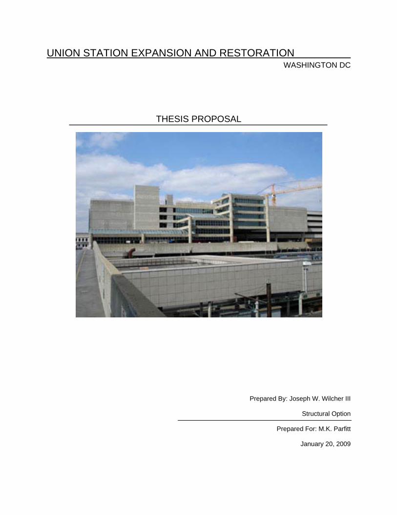
UNION STATION EXPANSION AND RESTORATION WASHINGTON DC
THESIS PROPOSAL
Prepared By: Joseph W. Wilcher III
Structural Option
Prepared For: M.K. Parfitt
January 20, 2009

Joseph W. Wilcher III Union Station Expansion Structural Option Washington DC Adviser: M. K. Parfitt Proposal January 20, 2009
Page 1 of 15
TABLE OF CONTENTS
Executive Summary .............................................................................................................. 2
Existing Structural System
Foundation ............................................................................................................... 3
Floor System ............................................................................................................ 3
Lateral System ......................................................................................................... 4
Problem Statement ............................................................................................................... 5
Proposed Solution ................................................................................................................. 5
Solution Method
Structural Analysis ................................................................................................... 6
Steel Connections .................................................................................................... 6
Architectural Breadth ............................................................................................... 7
Lighting Breadth ....................................................................................................... 7
Tasks & Tools ....................................................................................................................... 8
Schedule ............................................................................................................................... 10
Conclusion ............................................................................................................................ 11
Appendix A: Plans & Sections .............................................................................................. 12

Joseph W. Wilcher III Union Station Expansion Structural Option Washington DC Adviser: M. K. Parfitt Proposal January 20, 2009
Page 2 of 15
EXECUTIVE SUMMARY
Throughout the past three technical reports composed by the author, a detailed look at the existing
structural system of the expansion to Union Station, gravity and lateral systems, as well as exploring
different floor systems for the building was examined. All three technical reports have played a role in the
decision making of how to address the following two major concerns for Union Station: having an open
floor plan for the track, ground, and mezzanine levels and keeping the overall weight of the building low
since the soil is considered weak on the site. By addressing the following two concerns as well as trying
to come up with a signature concept for the expansion to Union Station in Washington DC, the author
went forward with these concepts in mind to come up with the following proposal.
The ultimate goal of this thesis will be to incorporate the following three structural studies:
1) Using a composite structural steel system as the floor system for levels one through three
2) Incorporating the use of king post trusses as transfer structures on the ground level
3) An alternative lateral system composed of braced frames
The main intent is to incorporate the king post trusses not only as a gravity load transfer element that can
support the new composite steel floor system, but to give a signature expression to the expansion of
Union Station as well as keeping the open floor plan to the lower levels. Since a brand new gravity
system is being incorporated into Union Station, the existing lateral system of moment frames will be
replaced with shear walls and the strength of serviceability of the system will be checked.
Two breadth studies will be accomplished within this thesis. The first breadth deals with the architectural
layout of the ground floor. Since the king post trusses will now be on the ground level, moving spaces
around as well as determining the correct areas for the busses to park and circulate around will be
addressed in this breadth. Within the lighting breadth, a lighting scheme for the king post trusses as well
as a new lighting plan for the bus terminal area will be determined to highlight the new architectural
feature.
Within this proposal, a more detailed problem statement, problem solution, and solution method can be
found. Since this is a demanding amount of work, a complete breakdown of tasks can be found on page 8
of this proposal as well as a calendar that tracks the preliminary effort to accomplish all the required work.
At the very end of the spring 2009 semester, the author will address the work done and present the
recommendations concluded to the jury.

Joseph W. Wilcher III Union Station Expansion Structural Option Washington DC Adviser: M. K. Parfitt Proposal January 20, 2009
Page 3 of 15
EXISTING STRUCTURAL SYSTEM
Foundation:
Union Station’s expansion main foundation system consists of concrete piles, which carry the load from
the train track stations to the soil and supportive columns for all the levels above the track level. Each one
rests upon a square footer that is either six feet or twelve feet in length and width, with a height of two
feet.
All the columns and piles are located between the eight locomotive rail ways that are part of Union
Station. Maximum diameter size of the columns and the piles are 1 ½’ and are spaced 22’-0” spanning in
the north-south direction of the building between the railroads.
From the provided geotechnical report, the net soil bearing capacity for the site is 1000 PSF, which is
considered weak for the soil. Fine to coarse sandy clay fill is the soil designation on the site for Union
Station. After examining the geotechnical report, each column supporting the structure above the track
level was designed to carry a typical load of 1000 kips to the ground.
Existing Floor System:
Union Station’s typical floor system is a two-way post-tension cast-in-place concrete slab with a thickness
of 7”. All the beams and girders are post-tension cast-in-place as well. In Union Station, the beams span
a length of 63’-0”. The girders located in the expansion, carry the load from the beams to the columns and
have a typical span of 24’-4” throughout the expansion. The concrete compressive strength for the slabs,
beams, and girders is f’c = 5000 psi while the columns supporting the floors are cast-in-place with a
compressive strength of 8000 psi. It is to be noted that the floor systems for the expansion and the
existing structure for Union Station do not connect with each other (Refer to Appendix A, Figure 1).
For the Ground Level, a rigid 6 ½” concrete slab was used for majority of the floor. A composite steel
design located along the west elevation was utilized to help reduce the weight within the weakest are of
the site. A 5” light weight concrete slab over 1 ½” gage LOK-Floor was used which makes the ground
floor total thickness to be 6 ½”. Shear studs sized at ¾” x 4 ½” were used in the composite floor design.
Typical member size for the beams is W27x84 which span 63’-0” and tie into a W33x118 girder. Each
girder ties into the concrete columns that are part of the foundation system.
There are two typical bay sizes located in the expansion of Union Station, 63’-0” x 27’-6” and 63’-0” x 40’-
0”. Since the tracks running through Union Station were the major consideration in the design as well as
the bus terminal, the use of long spans was concluded as the best approach for the design.

Joseph W. Wilcher III Union Station Expansion Structural Option Washington DC Adviser: M. K. Parfitt Proposal January 20, 2009
Page 4 of 15
Lateral System:
Union Station’s lateral load system is composed of ordinary reinforced concrete moment frames (To see a
plan view of all moment frames, see Appendix A, Figure 3). Lateral loads, as well as the gravity loads,
reach the foundation of Union Station by first traveling through the beams, then carry through the girders
which connect to the columns. From there, all loads travel down in the columns to the ground level and
then the columns take all the loads into the square footers. An expansion joint was placed between
column lines 7 and 7-1 (Refer to Appendix A, Figure 3) is located between the existing structure and the
expansion to Union Station. There is also an expansion joint within the expansion. This joint is used to
create two separate areas that can move independent of each other due vibrations and temperature
affects acting upon the building.
Joseph W. Wilcher III Union Station Expansion Structural Option Washington DC Adviser: M. K. Parfitt Proposal January 20, 2009
Page 5 of 15
PROBLEM STATEMENT
From the very start of the design for the expansion to Union Station, two major concerns for the building
were used as a starting point. First, there had to be large open spaces with a minimum amount of
columns for the track, ground, and mezzanine level. This is due to having a bus terminal located on the
ground floor since and the owner wanted an open feeling for the mezzanine level. Second, the weight of
the building should be at a minimum since the soil located on the site is considered poor. These two
considerations lead to the use of the post-tension floor system and above average column sizes
throughout the entire building.
On the upper floors, a large open space is not necessarily required since there is only office space and
parking. Since the large open floor plan was used throughout the building, deep post-tension members
were used on the upper level. As an alternative to the use of an open floor plan on the upper levels, the
author believes there could have been a more integrated for a structural floor plan used on the first
through third levels (Refer to Appendix A, Figure 2). Therefore, an alternative design for Union Station will
be proposed to address this issue as well as keeping the two major concerns into play as.
PROPOSED SOLUTION
Since the soil is considered weak according to the geotechnical report, a light structural system must be
used throughout the expansion in order to prevent settlement and any future problems with the
foundation. Since a post-tension floor system is considered a light structural system and was used in
Union Station, determining a floor system that weighs less will be a priority for the second concern to be
achieved.
Once a lighter floor system is selected, then the open plan concern can be addressed for Union Station.
To keep an open floor plan for the mezzanine and ground levels, the use of a transfer system can be an
alternative allowing columns at a long distance from each other. Since the ground floor has a bus
terminal, the transfer system will have to incorporate not only large distances in the horizontal direction,
but in the vertical direction as well. This is to allow the busses to travel and park safely without having a
concern of running into the transfer structure.

Joseph W. Wilcher III Union Station Expansion Structural Option Washington DC Adviser: M. K. Parfitt Proposal January 20, 2009
Page 6 of 15
SOLUTION METHOD
Structural Analysis:
From technical report two, the author discussed using a composite steel design for the upper floors while
creating a transfer level for the lower levels. Composite steel design not only helps reduce the height of
the structural members in Union Station on the upper levels, but is lighter in weight than a post-tension
concrete floor system (This deals with the second major concern addressed in the problem statement). In
order to address the long span concern for the lower levels, steel king post trusses will be designed on
the mezzanine and ground level. While the trusses act as transfer levels, they also keep the levels open
with no columns. Not only will the king post trusses serve as a structural component of Union Station, but
it will give the ground level a grand architectural feature which will act as a signature expression for the
expansion.
Since a re-design of the floor systems is proposed, a new lateral system will have to be developed for
both areas in the expansion to Union Station. Moment frames are used as the existing lateral system for
the expansion to Union Station and have the potential of being used again with the new structural system.
However, moment frames are expensive to use and the author believes they would not serve as the best
lateral system for the re-design. Instead of moment frames, braced frames will be investigated as the
lateral system located along the exterior walls of Union Station.
M.A.E. Integrated Study [Steel Connections]:
In accordance with the guidelines for the M.A.E. of this proposal, the author will investigated the types of
connections that can be used throughout the king post trusses used on the ground level. Determining the
affect each connection (Amount of bolts, welds, plates, cost, etc.) could have on the design and
optimization of the king post trusses will be taken into account. Once a connection is determined, a typical
connection between members of a truss will be designed and detailed to verify the possibility of using this
connection on the trusses on the transfer level.

Joseph W. Wilcher III Union Station Expansion Structural Option Washington DC Adviser: M. K. Parfitt Proposal January 20, 2009
Page 7 of 15
Architectural Breadth:
Within this breadth, the author will look at the architectural layout for the ground level. Since the king post
trusses will be incorporated as not only part of the structural design, but as an architectural feature as
well, the author will determine a new functional layout that allows the busses to park by and travel through
each truss. In order to achieve the proper use of shear walls as the new lateral system in the expansion
to Union Station, moving the mechanical rooms, stairwells, elevator towers, and lobbies around will be
accomplished. It is important to note that the new locations of the above mentioned rooms will be
addressed in the upper levels as well.
Lighting Breadth:
Since the architecture floor plan on the ground level will change due to the king post trusses, a new
lighting system for the level will be incorporated. A lighting scheme will be used to illuminate each king
post trusses throughout the ground floor to express the signature idea within the expansion to Union
Station. In addition to lighting the king post trusses, a new lighting plan for the bus terminal on the ground
floor will be designed as well. This is to ensure the proper balance between natural day lighting and the
required foot candles needed to light this portion of Union Station.

Joseph W. Wilcher III Union Station Expansion Structural Option Washington DC Adviser: M. K. Parfitt Proposal January 20, 2009
Page 8 of 15
TASKS & TOOLS
The following list of tasks will be completed in the investigation of the mentioned proposals as well as the
required tools.
Task 1: Location
• Research King Post Truss Styles • Determine Location of King Post Trusses • Re-Locate Mechanical Room, Stairwells, Elevator Towers, & Rest of Ground Floor Areas [Arch. Breadth] • Modify Upper-Level Stairwells, Elevator Towers, & Other Areas to Match Ground Floor [ Arch. Breadth] • Determine Location For Brace Frames
Task 2: Bay Size
• Determine New Bay Sizes For Levels 1 Through 3
Task 3: Gravity System (Levels 1 Through 3)
• Establish Dead, Live, & Snow Loads Using ASCE 7-05 • Determine Preliminary Slab & Member Sizes • Design RAM Model For Composite Steel Floor System • Finalize Gravity System
Task 4: King Post Trusses (Mezzanine & Ground Levels)
• Determine Design of King Post Trusses • Establish Dead & Live Loads Going Into Trusses • Determine Preliminary Member Sizes • Design King Post Trusses In ETABS • Verify Truss Dimensions Work On Each Level
Task 5: Lateral System
• Establish Wind & Seismic Loads Using ASCE 7-05 • Determine Load Distribution To Each Brace Frame • Design Lateral Model In ETABS • Check Strength & Serviceability of Lateral System
Task 6: Foundations
• Verify Loads on Foundation • Perform Spot Checks on Footings

Joseph W. Wilcher III Union Station Expansion Structural Option Washington DC Adviser: M. K. Parfitt Proposal January 20, 2009
Page 9 of 15
Task 7: Connections
• Research Types of Connections Used on King Post Trusses • Determine Typical Connections • Design Typical Connections as Appropriate
Task 8: Architectural Breadth
• Verify Location of Areas Discussed in Task 1 • Determine New Loading Areas For Buses on Ground Level • Determine Vehicular Circulation on Ground Level
Task 9: Lighting Breadth
• Determine Required Foot-Candles For Bus Terminal • Select Luminaries to Highlight King-Post Trusses as a Feature • Select Luminaries For Bus Terminal • Verify Luminaries Meet Requirements For Foot-Candles
Task 10: Write Report
Task 11: Develop Presentation

Joseph W. Wilcher III Union Station Expansion Structural Option Washington DC Adviser: M. K. Parfitt Proposal January 20, 2009
Page 10 of 15
SCHEDULE
Task 1: Location Task 7: Connections
Task 2: Bay Size Task 8: Architectural Breadth
Task 3: Gravity System (Levels 1 Through 3) Task 9: Lighting Breadth
Task 4: King Post Trusses (Mezzanine & Ground Levels) Task 10: Write Report
Task 5: Lateral System Task 11: Develop Presentation
Task 6: Foundations

Joseph W. Wilcher III Union Station Expansion Structural Option Washington DC Adviser: M. K. Parfitt Proposal January 20, 2009
Page 11 of 15
CONCLUSION
At the end of the spring 2009 semester, a new structural floor system with the use of king post trusses
acting as a transfer element and a new lateral system will be designed as the structural depth of this
thesis. Both the architectural and lighting breadth will be used to not only show the author’s knowledge of
the other options of architectural engineering, but to show how using the king post trusses will change
certain aspects of Union Station.
While the intent of this thesis is to understand why certain choices were made regarding the floor and
lateral system, building layout, and lighting system, it is early to conclude on whether better choices were
selected by the author or if the original design was the best choice for the expansion to Union Station.
After all necessary steps and calculations are taken into account; the author will present to the jury and
conclude what was the best choice for the expansion to Union Station.

Joseph W. Wilcher III Union Station Expansion Structural Option Washington DC Adviser: M. K. Parfitt Proposal January 20, 2009
Page 12 of 15
APPENDIX A: PLANS & SECTIONS

Joseph W. Wilcher III Union Station Expansion Structural Option Washington DC Adviser: M. K. Parfitt Proposal January 20, 2009
Page 13 of 15
Figure 1: Typical Floor Plan for Union Station

Joseph W. Wilcher III Union Station Expansion Structural Option Washington DC Adviser: M. K. Parfitt Proposal January 20, 2009
Page 14 of 15
Figure 2: Section of Union Station

Joseph W. Wilcher III Union Station Expansion Structural Option Washington DC Adviser: M. K. Parfitt Proposal January 20, 2009
Page 15 of 15
Figure 3: Moment Frame Designation