unique identifier: 34-1635 - prepayment · pdf file · 2010-12-01unique identifier:...
TRANSCRIPT
ESKOM COPYRIGHT PROTECTED
B Morrison / November 2010 / Rev 1
SPECIFICATION
Document Classification: Controlled Disclosure Title: Distribution Specification – Part 25:
PARTICULAR REQUIREMENTS FOR PREPAYMENT METERS
Unique Identifier: 34-1635 Document Type: DSP Revision: 1
Published date: NOVEMBER 2010
Total pages: 24 Review date: NOVEMBER 2015
COMPILED BY APPROVED BY FUNCTIONAL RESP AUTHORISED BY
_ _ _ _ _ _ _ _
J O’KENNEDY
_ _ _ _ _ _ _ _
J O’KENNEDY
_ _ _ _ _ _ _ _
PR GROENEWALD
_ _ _ _ _ _ _ _
MN BAILEY
Chief Engineer Study Committee for TESCOD CMDT for MD (Dx)
DATE: 02/11/2010 DATE: 02/11/2010 DATE: 12/11/2010 DATE: ………………….
Content Page
Foreword .............................................................................................................................................. 2 1 Scope ......................................................................................................................................... 3 2 Normative references................................................................................................................. 3 3 Definitions and abbreviations ..................................................................................................... 4
3.1 Definitions ........................................................................................................................ 5 3.2 Abbreviations ................................................................................................................... 5
4 Requirements ............................................................................................................................. 6 4.1 Fundamental requirements for meters ............................................................................. 6 4.2 Mechanical requirements ................................................................................................. 6 4.3 Conformal coating ............................................................................................................ 7 4.4 Tamper sensor ................................................................................................................. 7 4.5 Sealing ............................................................................................................................. 7 4.6 Marking of meter for all meter types ................................................................................ 8 4.7 Interface port .................................................................................................................... 9 4.8 Climatic requirements .................................................................................................... 12 4.9 Electrical requirements................................................................................................... 12 4.10 Functional requirements................................................................................................. 14 4.11 STS token entry and decryption ..................................................................................... 16 4.12 Other requirements ........................................................................................................ 18
5 Packaging ................................................................................................................................ 18 Annex A – Short Code instructions .................................................................................................... 19 Annex B - Impact assessment ........................................................................................................... 21
DOCUMENT CLASSIFICATION: CONTROLLED DISCLOSURE PARTICULAR REQUIREMENTS FOR PREPAYMENT METERS
Unique Identifier: 34-1635 Type: DSP Revision: 1 Page: 2 of 24
ESKOM COPYRIGHT PROTECTED
When downloaded from the IARC WEB, this document is uncontrolled and the responsibility rests with the user to ensure it is in line with the authorised version on the WEB.
Foreword
This specification was originally published in October 1993 as MC 171 Rev.1.0. Subsequent modifications to the specification took MC 171 to Rev.4.11 with additions like the meter interface port and standard indicator requirements.
MC171 has subsequently been re-formatted in accordance with the Eskom Documentation System and issued as SCSSCAAA9 rev 0 with minor modifications only.
SCSSCAAA9 rev 1 and 2 introduced a number of small additions, mainly some minimum requirements for split meters and three-phase meters. Later additions include a standard meter map to replace the manufacturer meter map for the interface port as well as minimum requirements for split meters and three phase meters.
With the adoption of the international IEC 62055 series of prepayment specifications, significant modifications were required for the local, Eskom and SANS prepayment specifications which all refer to the international specifications. This revised Eskom specification is therefore released as document DSP 34-1635.
Revision history
This revision cancels and replaces revision no 0 of specification DSP 34-1635.
Date Rev. Clause Remarks Nov 2010 1
4.7.2.2 Compiled By: J. O’Kennedy Correct image for USB receptacle and include clearance dimensions.
Dec 2009 0 All Compiled By: J. O’Kennedy
- The number document number change to 34-1635 Complete revision of original specification to refer to IEC 62055 series of specifications, as well as the new release of SANS 1524-1
- The associated STS Companion specifications are also used because STS has since been accepted as an international standard
Authorisation
This document has been seen and accepted by:
Name Designation
MN Bailey Corporate Manager Divisional Technology
PR Groenewald Technology Development Manager (Control Plant)
J O’Kennedy Measurements Study Committee
This specification shall apply throughout Eskom Holdings Limited, its divisions, subsidiaries and entities wherein Eskom has a controlling interest.
DOCUMENT CLASSIFICATION: CONTROLLED DISCLOSURE PARTICULAR REQUIREMENTS FOR PREPAYMENT METERS
Unique Identifier: 34-1635 Type: DSP Revision: 1 Page: 3 of 24
ESKOM COPYRIGHT PROTECTED
When downloaded from the IARC WEB, this document is uncontrolled and the responsibility rests with the user to ensure it is in line with the authorised version on the WEB.
Development team
Name Designation
J O’Kennedy Eskom IARC Control Technologies
E Makwarela Eskom IARC Control Technologies
Keywords
Meter, prepayment, prepaid, ED, ECU, split meter, single phase, three phase, Electricity Dispenser, Electricity Control Unit.
Bibliography
http://www.prepayment.eskom.co.za/ Eskom prepayment web site with specifications and requirements
http://bits.eskom.co.za/ Eskom Distribution (subscription site) with electrification standards
http://www.sts.org.za/ STS Association web site (The owners of the STS Specifications.)
1 Scope
SANS 1524-1 specifies the minimum requirements for a prepayment meter but it does not specifically deal with the product functionality. Many requirements in SANS 1524-1 incorporate various options and some requirements are currently only preferred options. This specification stipulates the detailed functional requirements to achieve the standardisation of prepayment meters within Eskom and to ensure that the equipment will fulfil Eskom's specific needs.
Since the original development of the Electricity Dispenser, various other concepts for prepayment meters have been developed. While this specification makes provision for Electricity Dispensers [EDs] and Electricity Control Units [ECUs], it is also applicable for three phase prepayment meters as well as for all variations of split prepayment meter designs.
2 Normative references
Parties using this document shall apply the most recent edition of the documents listed below:
IEC 62051 Electricity metering – Glossary of terms
IEC 62052-11 Electricity metering - General requirements, Tests and test conditions - Part 11: Metering equipment
IEC 62053-21 Electricity metering equipment (a.c.) – Part 21: Particular requirements – Static meters for active energy (classes 1 and 2)
IEC 62055-21 Electricity metering – Payment systems – Part 21: Framework for standardisation
IEC 62055-31 Electricity payment metering systems – Part 31: Particular requirements – Static payment meters for active energy (classes 1 & 2)
DOCUMENT CLASSIFICATION: CONTROLLED DISCLOSURE PARTICULAR REQUIREMENTS FOR PREPAYMENT METERS
Unique Identifier: 34-1635 Type: DSP Revision: 1 Page: 4 of 24
ESKOM COPYRIGHT PROTECTED
When downloaded from the IARC WEB, this document is uncontrolled and the responsibility rests with the user to ensure it is in line with the authorised version on the WEB.
IEC 62055-41 Electricity metering – Payment systems – Part 41: Standard transfer specification (STS ) – Application layer protocol for one-way token carrier systems
IEC 62055-51 Electricity metering – Payment systems – Part 51: Standard transfer specification – Physical layer protocol for one-way numeric and magnetic card token carriers
IEC 62055-52 Electricity metering – Payment systems – Part 52: Standard transfer specification – Physical layer protocol for a two-way virtual token carrier for direct local connection
BS 7856 Code of practice for Design of alternating current, watthour meters for active energy (classes 1 and 2)
SANS 10142-1 The wiring of premises - Part 1: Low-voltage installations
SANS 1524-1 Electricity payment systems - Part 1: Payment meters
SANS 1524-1-1 Electricity payment systems - Part 1-1: Mounting and terminal requirements for payment meters
SANS 1524-1-2 Electricity payment systems - Part 1-2: Specification for surge arresters for the protection of electricity dispensers
SANS 1524-4 Electricity payment systems - Part 4: National prepayment electricity meter cards
SANS 15417 Information technology: Automatic identification and data capture techniques - Code 128 bar code symbology specification
SANS 156 Moulded-case circuit-breakers
SANS 767-1 Earth leakage protection units - Part 1: Fixed earth leakage protection circuit-breakers
STS 101-1 Interface specification - STS 101-1: Standard transfer specification (STS) – Physical layer mechanical and electrical interface for virtual token carriers
STS 201-15.1.0 Companion specification - STS 201-15.1.0: Standard transfer specification (STS) – Meter function object: Register Table for electricity payment meters
DSP 34-749 Eskom specification: Standard for sealing metering equipment
DSP 34-1527 Eskom specification: Procedure for producing software process assessment documents.
DPC 34-1466 Eskom specification: Procedure for the Request For Modification (RFM) on prepaid meters
RES/RR/00/11740
Eskom specification: Accelerated Environmental Stress Test for Pre-payment metering
3 Definitions and abbreviations
The terms and definitions given in IEC 62051, IEC 62052-11, IEC 62055-21, IEC 62055-31 and IEC 62055-41, as well as the following, apply:
DOCUMENT CLASSIFICATION: CONTROLLED DISCLOSURE PARTICULAR REQUIREMENTS FOR PREPAYMENT METERS
Unique Identifier: 34-1635 Type: DSP Revision: 1 Page: 5 of 24
ESKOM COPYRIGHT PROTECTED
When downloaded from the IARC WEB, this document is uncontrolled and the responsibility rests with the user to ensure it is in line with the authorised version on the WEB.
3.1 Definitions
Active unit: The metering unit that plugs into the passive unit (or socket). The Active unit may often (but not necessarily) include the User Interface Unit.
Base: The back cover of the active unit. The active unit will plug into a standard socket.
Measurement Unit:
As defined in SANS 1524-1 with the additional meaning that the term measurement unit may also be used to describe a complete meter where the Measurement Unit and User Interface Unit are contained inside a single device.
Overcurrent Protection:
A function provided by ECU to serve as a fault protection feature by disconnecting the load when a fault current is detected.
Passive Unit: Also called a socket (for conformity with IEC terminology). The service connection is terminated in the passive unit and the active unit plugs into the passive unit.
Power Limiting: An automatic load disconnection function provided in prepayment meters to limit the average power consumed, to the value programmed in the meter with the relevant STS management token. The average power consumed is calculated over a number of pulses and is therefore not suitable to serve as input for any protection feature.
Prepayment Meter:
A generic term for prepayment devices encompassing ED, ECU, split ED and other metering devices. This term is also interchangeably used with the word "meter" in the same context.
Socket: The passive unit where the service connection is terminated. The active unit plugs into the socket.
Split Meter Meter where the measurement unit and User Interface Unit are contained in separate enclosures.
Token Carrier: As defined in IEC 62055-31
Token Carrier Interface:
As defined in IEC 62055-31
User Interface Unit:
The portion of a meter that contains interfaces (input and/or output) to interact with the meter. The User Interface Unit is often included with the Measurement Unit to form a self contained meter, but it may also exist as a separate Unit e.g. in the implementation of a split meter.
3.2 Abbreviations
APDU: Application Protocol Data Unit (As defined in IEC 62055-41)
ASCII: American Standard Code for Information Interchange.
BCD: Binary Coded Decimal.
CIU: Customer Interface Unit
ECU: Electricity Control Unit; A prepayment meter with earth leakage and overcurrent protection built in. Category as defined in SANS 1524-1

DOCUMENT CLASSIFICATION: CONTROLLED DISCLOSURE PARTICULAR REQUIREMENTS FOR PREPAYMENT METERS
Unique Identifier: 34-1635 Type: DSP Revision: 1 Page: 6 of 24
ESKOM COPYRIGHT PROTECTED
When downloaded from the IARC WEB, this document is uncontrolled and the responsibility rests with the user to ensure it is in line with the authorised version on the WEB.
ED: Electricity Dispenser. A prepayment meter without either earth leakage or overcurrent protection. Category as defined in SANS 1524-1
HHU: Hand Held Unit.
ISO: International Organization for Standardization
MSN: Most Significant Nibble.
RAM: Random Access Memory.
ROM: Read Only Memory.
SGC: Supply Group Code
STS: Standard Transfer Specification
TCDU: Transportation Class Data Unit (As defined in IEC 62055-41)
UIU: See CIU - Customer Interface Unit
VTC: Virtual Token Carrier
4 Requirements
4.1 Fundamental requirements for meters
All meters shall comply with the requirements of SANS 1524-1 unless differences are defined in this specification which will take precedence.
4.2 Mechanical requirements
4.2.1 Single phase meters designed as a self contained unit:
Single phase prepayment meters that are not designed as split meters (EDs and ECUs) shall be constructed in accordance with the requirements of SANS 1524-1-1.
The internal components in the active part of the meter shall be protected against unintentional damage during handling and installation in the field.
Provision shall be made for the meter to plug into a standard socket as defined in SANS 1524-1-1, sheets 1 and 2.
The prepayment meter shall not encroach into the reserved volumes indicated in SANS 1524-1-1, sheet 4.
Prepayment meters that do not provide earth fault and overcurrent protection, shall be constructed in such a way that the active unit cannot be successfully inserted into the socket without first removing the extra tab, which is indicated in the relevant detail drawing in SANS 1524-1-1, sheet 1, section B-B.
It shall be possible to insert meters that incorporate earth fault and overcurrent protection, into the socket, with the tab indicated in the detail drawing, still in place.
DOCUMENT CLASSIFICATION: CONTROLLED DISCLOSURE PARTICULAR REQUIREMENTS FOR PREPAYMENT METERS
Unique Identifier: 34-1635 Type: DSP Revision: 1 Page: 7 of 24
ESKOM COPYRIGHT PROTECTED
When downloaded from the IARC WEB, this document is uncontrolled and the responsibility rests with the user to ensure it is in line with the authorised version on the WEB.
4.2.2 Multi phase meters and all meters designed as split meters
Multi phase prepayment meters, and all split prepayment meters shall be designed to adhere to one of the following two enclosure options:
1) The base of the measurement unit shall conform to the BS 7856 enclosure and mounting arrangement. The terminals position and spacing shall be according to the same BS requirements with the addition that clamp screw terminals are optionally allowed. The measurement unit shall be in a high impact resistant case. The meter cover shall be dust-proof and sealable. If a terminal block cover is provided, the cover shall be sealable independently from the meter cover.
2) The measurement unit enclosure shall conform to the standard circuit breaker enclosure format that is suitable for mounting on a 35 mm DIN rail or alternatively with dual-rail mounting capability.
4.3 Conformal coating
The prepayment meter shall be protected against malfunction due to the ingress of vermin, by conformal coating the printed circuit boards in the meter, as much as practical.
4.4 Tamper sensor
A tamper sensor that senses entry into the measurement unit enclosure and disconnects the load, shall not be fitted. Alternatively, if a sensor is fitted, it shall be permanently disabled by the manufacturer. A configuration setting that can be enabled again by a field usable engineering code is not a sufficient method of disabling.
Tamper or fraud detection measures which are automatically set and reset by meter registers, may optionally be provided. Some such measures have been identified and are indicated in the STS Companion specification, STS 201-15.1.0
4.5 Sealing
Provision shall be made for sealing of the measurement unit with stainless steel seal wires in accordance with DSP 34-749. Where the terminals are contained inside the enclosure, they may be sealed with the same seal(s) as the enclosure.
Where implemented, the stainless steel seals shall be applied in such a way that it will not be possible to undo/loosen the mounting screws used to secure the measurement unit to the socket, without breaking these seals. It shall further be impossible to obtain access to the inside of the measurement unit or to the connection terminals without breaking the seals.
The stainless steel seals shall be applied in such a way that they will be easily visible when viewing an installed measurement unit from the front.
Any additional parts or cover plates that may be required to install or seal a meter shall be supplied with the meter.
It shall be possible to install, remove and seal a meter without requiring any special tools, apart from the standard Eskom sealing pliers. (This requirement excludes standard Field Technician tools like screwdrivers, pliers, side cutters etc.)
Also refer to clause 4.7 for further sealing requirements of interface ports.
DOCUMENT CLASSIFICATION: CONTROLLED DISCLOSURE PARTICULAR REQUIREMENTS FOR PREPAYMENT METERS
Unique Identifier: 34-1635 Type: DSP Revision: 1 Page: 8 of 24
ESKOM COPYRIGHT PROTECTED
When downloaded from the IARC WEB, this document is uncontrolled and the responsibility rests with the user to ensure it is in line with the authorised version on the WEB.
4.6 Marking of meter for all meter types
The meter number (decoder reference number) and barcode shall be clearly and permanently displayed on the front of the measurement unit enclosure as defined in SANS 1524-1 clause 5.1. (Note that the Manufacturer Codes for prepayment meters are administered by the STS Association and are different from the codes used for conventional meter manufacturers.)
It shall be possible to clearly display the meter number(s) on the CIU for the currently active measurement unit of a split meter. It shall further be possible to change the displayed number(s) accordingly whenever the measurement unit or the CIU is replaced.
The user interface on the meter, as well as on the CIU for a split meter, shall display the STS compliant logo at least 7mm high and clearly visible from the front of the installed device. The measurement unit for a split meter shall also display the STS logo to be visible when the unit is installed, but it may be smaller in size.
Other information as defined in SANS 1524-1 clause 5.1 shall also be displayed.
Every measurement unit and CIU shall clearly signify the following matching colour indications, to facilitate easy identification of the communication type for the main user interface:
White or none - No remote interface provided (i.e. not a split meter)
Grey or black - Power Line Carrier
Yellow or orange - Pilot Wire communication
Blue or green - RF communication
Pink or purple - Other communication type
Red - Reserved
4.6.1 Manufacturing and configuration information marked on all meters
The following minimum manufacture/configuration related information shall be visible from the outside of an uninstalled measurement unit. The information shall be protected in such a manner that it is not possible for a customer to delete, change or otherwise make illegible the information displayed on an installed measurement unit. It is therefore recommended that this information be applied to the back cover of the measurement unit, or to the side of a circuit breaker format enclosure.
1) Meter model/version number (as per RFM or meter approval.) Refer to document DPC 34-1466 for further information.
2) Date of manufacture (a tolerance of two weeks will be allowed for this date)
3) Supply Group Code
4) Tariff index
5) Amp limit or Power limit
6) Calibration accuracy
7) Interface type to the CIU for a split meter, e.g. Power Line, Pilot Wire or RF Comms
DOCUMENT CLASSIFICATION: CONTROLLED DISCLOSURE PARTICULAR REQUIREMENTS FOR PREPAYMENT METERS
Unique Identifier: 34-1635 Type: DSP Revision: 1 Page: 9 of 24
ESKOM COPYRIGHT PROTECTED
When downloaded from the IARC WEB, this document is uncontrolled and the responsibility rests with the user to ensure it is in line with the authorised version on the WEB.
4.6.2 Additional marking required on ECU
The following minimum information shall be legibly and indelibly marked on the ECU. This information shall be visible on the front of the enclosure.
1) The designation "ECU", in letters at least 4 mm high.
2) The maximum (rated) current in Amps.
3) The earth leakage protection unit sensitivity in mA.
4) The overcurrent breaking capacity in kA.
5) A message, located close to the earth leakage test button, with the legend: “Test often. If unit does not switch off, seek advice.” or similar.
4.7 Interface port
The communication interface to the CIU of a split meter is not specified and implementation thereof is left for the discretion of the manufacturer.
The prepayment meter shall have an interface port that may be used for connection to a HHU, meter configuration tool or other communication device.
It shall be possible to inject all the supported STS tokens via the port and read the results where provided. It shall also be possible to read and/or write all the mandatory registers directly through the port as defined in STS Companion specification, STS 201-15.1.0. (FOIN 15.001.01)
Additional proprietary information may optionally be transferred through this port, but it shall not be possible to change any settings which are normally encrypted under STS, or insert credit into the meter, unless such information is encrypted as STS tokens.
The physical communication interfaces are defined as the following two Interface Types for the different meter implementations:
4.7.1 Type A interface
This is the industry standard interface for use in meters designed as a self contained unit; (i.e. ED and ECU devices).
The interface shall comply with the Mechanical and Electrical requirements as specified for the Type A interface in STS Interface specification STS 101-1.
Access to the port of an installed meter shall only be possible after the Eskom approved seals have been broken.
Unconstrained access to the port of an uninstalled meter is preferred, to simplify meter encoding in Eskom stores.
It shall be possible to read and write the information through the port of the prepayment meter without having to apply mains power to the meter. It shall further be possible to read the information even if the meter’s user interface or power supply has failed.
The meter shall be supplied with a reusable seal/plug to prevent contamination by vermin when the port is unused.
DOCUMENT CLASSIFICATION: CONTROLLED DISCLOSURE PARTICULAR REQUIREMENTS FOR PREPAYMENT METERS
Unique Identifier: 34-1635 Type: DSP Revision: 1 Page: 10 of 24
ESKOM COPYRIGHT PROTECTED
When downloaded from the IARC WEB, this document is uncontrolled and the responsibility rests with the user to ensure it is in line with the authorised version on the WEB.
4.7.2 Type B interface
This section for the Type B interface replaces clause 6 in STS Interface specification STS 101-1. Note that the communication protocol for the Type B interface remains the same as that used for the Type A interface.
4.7.2.1 General
The Type B interface is based on the Micro USB (type B) receptacle and is the Eskom standard interface for use in all split meters; (i.e. measurement units that conform to the BS 7856 enclosure format as well as units that conform to the circuit breaker enclosure format.)
The Micro USB (type B) receptacle is an industry standard connection, which is used in the consumer electronics market, world wide. It is intended for use with clients over a direct local connection, but the connection can be extended over a suitable modem link.
The connection optically isolates the client from the server and as such, no power is provided to the client from the server.
The need for the PowerDownDisable signal also falls away.
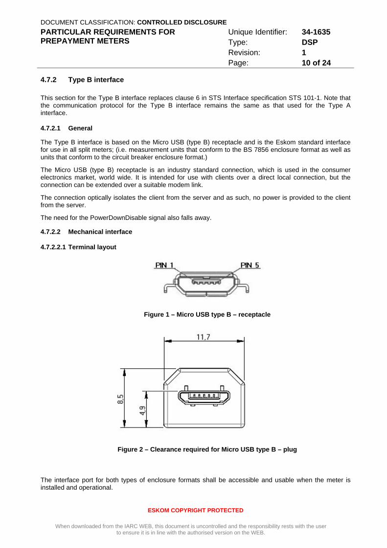
4.7.2.2 Mechanical interface
4.7.2.2.1 Terminal layout
Figure 1 – Micro USB type B – receptacle
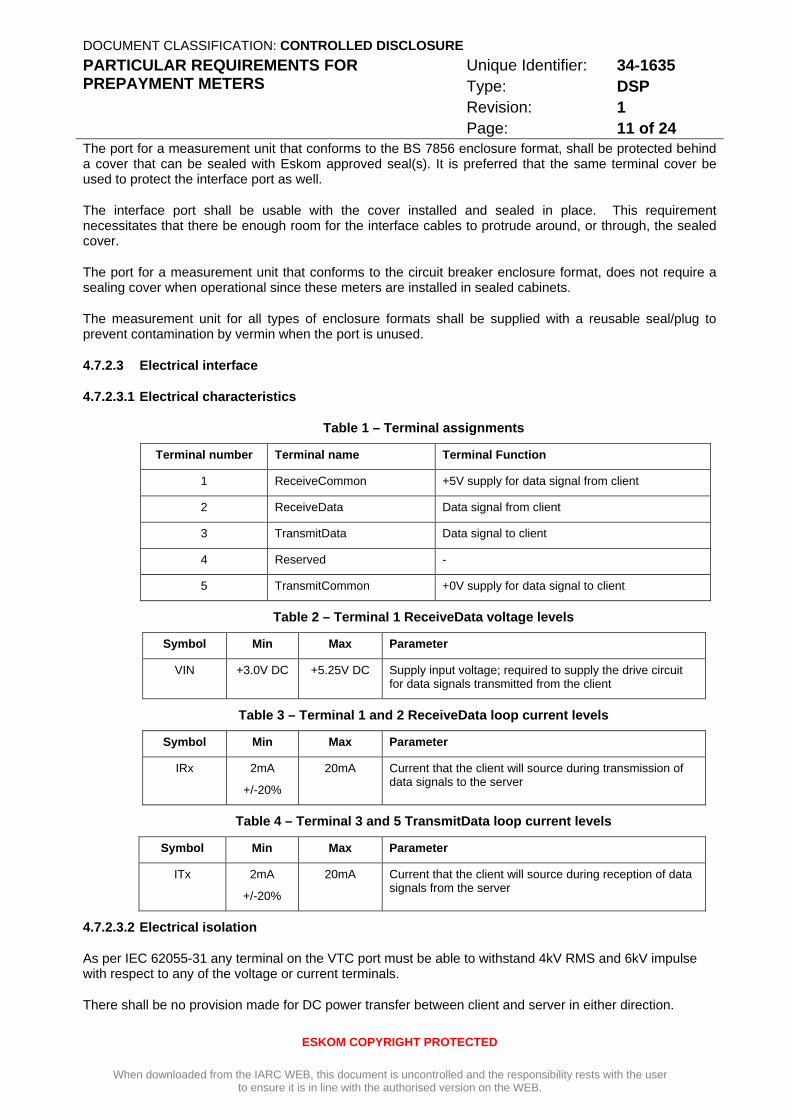
Figure 2 – Clearance required for Micro USB type B – plug
The interface port for both types of enclosure formats shall be accessible and usable when the meter is installed and operational.
DOCUMENT CLASSIFICATION: CONTROLLED DISCLOSURE PARTICULAR REQUIREMENTS FOR PREPAYMENT METERS
Unique Identifier: 34-1635 Type: DSP Revision: 1 Page: 11 of 24
ESKOM COPYRIGHT PROTECTED
When downloaded from the IARC WEB, this document is uncontrolled and the responsibility rests with the user to ensure it is in line with the authorised version on the WEB.
The port for a measurement unit that conforms to the BS 7856 enclosure format, shall be protected behind a cover that can be sealed with Eskom approved seal(s). It is preferred that the same terminal cover be used to protect the interface port as well.
The interface port shall be usable with the cover installed and sealed in place. This requirement necessitates that there be enough room for the interface cables to protrude around, or through, the sealed cover.
The port for a measurement unit that conforms to the circuit breaker enclosure format, does not require a sealing cover when operational since these meters are installed in sealed cabinets.
The measurement unit for all types of enclosure formats shall be supplied with a reusable seal/plug to prevent contamination by vermin when the port is unused.
4.7.2.3 Electrical interface
4.7.2.3.1 Electrical characteristics
Table 1 – Terminal assignments
Terminal number Terminal name Terminal Function
1 ReceiveCommon +5V supply for data signal from client
2 ReceiveData Data signal from client
3 TransmitData Data signal to client
4 Reserved -
5 TransmitCommon +0V supply for data signal to client
Table 2 – Terminal 1 ReceiveData voltage levels
Symbol Min Max Parameter
VIN +3.0V DC +5.25V DC Supply input voltage; required to supply the drive circuit for data signals transmitted from the client
Table 3 – Terminal 1 and 2 ReceiveData loop current levels
Symbol Min Max Parameter
IRx 2mA
+/-20%
20mA Current that the client will source during transmission of data signals to the server
Table 4 – Terminal 3 and 5 TransmitData loop current levels
Symbol Min Max Parameter
ITx 2mA
+/-20%
20mA Current that the client will source during reception of data signals from the server
4.7.2.3.2 Electrical isolation
As per IEC 62055-31 any terminal on the VTC port must be able to withstand 4kV RMS and 6kV impulse with respect to any of the voltage or current terminals.
There shall be no provision made for DC power transfer between client and server in either direction.
DOCUMENT CLASSIFICATION: CONTROLLED DISCLOSURE PARTICULAR REQUIREMENTS FOR PREPAYMENT METERS
Unique Identifier: 34-1635 Type: DSP Revision: 1 Page: 12 of 24
ESKOM COPYRIGHT PROTECTED
When downloaded from the IARC WEB, this document is uncontrolled and the responsibility rests with the user to ensure it is in line with the authorised version on the WEB.
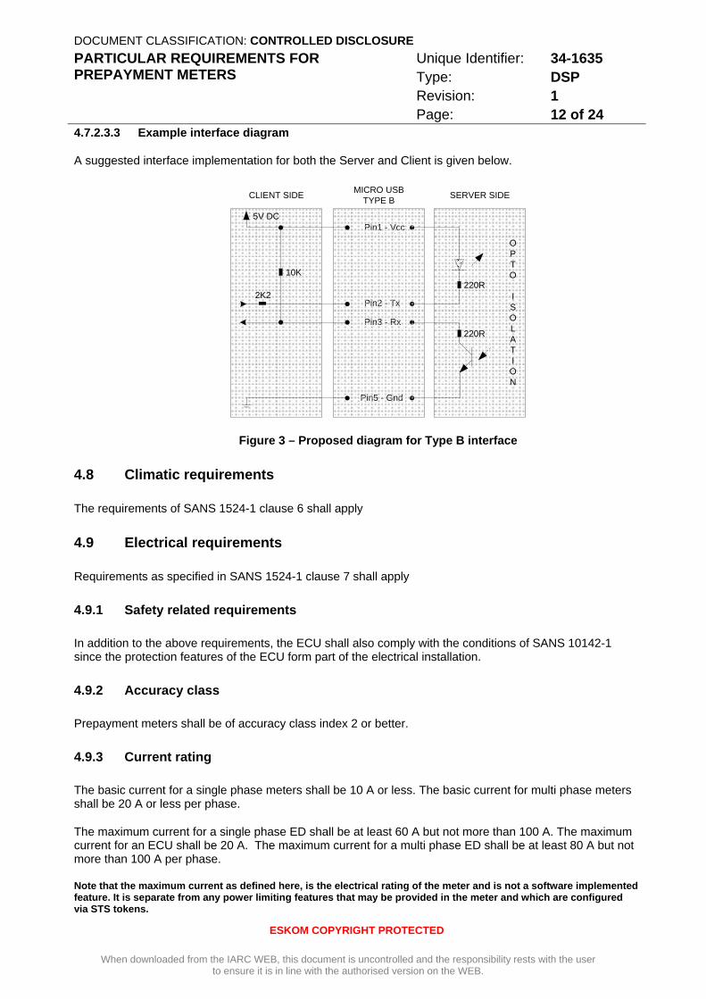
4.7.2.3.3 Example interface diagram
A suggested interface implementation for both the Server and Client is given below.
SERVER SIDE
Pin1 - Vcc
Pin2 - Tx
Pin3 - Rx
Pin5 - Gnd
OPTO
ISOLATION
MICRO USBTYPE BCLIENT SIDE
5V DC
2K2
10K
220R
220R
Figure 3 – Proposed diagram for Type B interface
4.8 Climatic requirements
The requirements of SANS 1524-1 clause 6 shall apply
4.9 Electrical requirements
Requirements as specified in SANS 1524-1 clause 7 shall apply
4.9.1 Safety related requirements
In addition to the above requirements, the ECU shall also comply with the conditions of SANS 10142-1 since the protection features of the ECU form part of the electrical installation.
4.9.2 Accuracy class
Prepayment meters shall be of accuracy class index 2 or better.
4.9.3 Current rating
The basic current for a single phase meters shall be 10 A or less. The basic current for multi phase meters shall be 20 A or less per phase.
The maximum current for a single phase ED shall be at least 60 A but not more than 100 A. The maximum current for an ECU shall be 20 A. The maximum current for a multi phase ED shall be at least 80 A but not more than 100 A per phase.
Note that the maximum current as defined here, is the electrical rating of the meter and is not a software implemented feature. It is separate from any power limiting features that may be provided in the meter and which are configured via STS tokens.
DOCUMENT CLASSIFICATION: CONTROLLED DISCLOSURE PARTICULAR REQUIREMENTS FOR PREPAYMENT METERS
Unique Identifier: 34-1635 Type: DSP Revision: 1 Page: 13 of 24
ESKOM COPYRIGHT PROTECTED
When downloaded from the IARC WEB, this document is uncontrolled and the responsibility rests with the user to ensure it is in line with the authorised version on the WEB.
4.9.4 Protection disconnect
As defined by SANS 1524-1 clause 7.9 and IEC 62055-31 Annex C
4.9.5 Power Limit and Out of Credit disconnect
The prepayment meter shall have a power limiting function that will automatically disconnect the load when the average power consumed, exceeds the maximum allowed. This function is not intended as a system protection feature.
The prepayment meter shall be able to decrement the credit register past zero, into negative values, if the load is not successfully disconnected when all available credit has been consumed. The negative credit value shall then be subtracted from any new credit entered into the meter.
The disconnection device (for "Power Limiting" and "Out of Credit" conditions) may be single-pole and shall be adequately protected to ensure that disconnection of the load circuit cannot be prevented by external influences e.g. magnetic field interference or mechanical intrusion/damage. (See clause 4.9.8)
The prepayment meter shall store the remaining credit to non volatile memory at intervals of not greater than 25 kWh. This requirement shall be in addition to any other storage mechanisms that are employed.
4.9.6 Additional requirements for prepayment meters with internal load switches
If an internal load switch is used as a disconnection device, the prepayment meter shall comply with the additional requirements specified in IEC 62055-31 Annex C.
4.9.6.1 General switching criteria
The prepayment meter shall automatically switch the load switch to the "on" state when the supply to the meter is available and the following conditions exist:
1) There is credit available
2) The meter is not in a tampered state;
3) The meter is not in a power limiting state
4) There is not an earth fault or overload condition detected by the meter.
The meter shall not have an interface that will allow the user to manually switch the load switch to the “on” position, apart from the normal function to enter credit which may indirectly cause the load switch contacts to close. (Such a manual button/interface will provide an easy means for the user to switch into intentional faults in attempts to fuse the contacts together.)
4.9.6.2 Power limiting switch criteria
The following procedure shall be employed, to restrict the number of switching cycles, when the meter is disconnecting the load, in order to limit the average power consumed:
1) Reconnect the load up to five times with 30 s intervals, if the consumption is more than the programmed limit
2) After five attempts, wait for 30 min (the lockout period) if the consumption is still above the limit before repeating the procedure.
DOCUMENT CLASSIFICATION: CONTROLLED DISCLOSURE PARTICULAR REQUIREMENTS FOR PREPAYMENT METERS
Unique Identifier: 34-1635 Type: DSP Revision: 1 Page: 14 of 24
ESKOM COPYRIGHT PROTECTED
When downloaded from the IARC WEB, this document is uncontrolled and the responsibility rests with the user to ensure it is in line with the authorised version on the WEB.
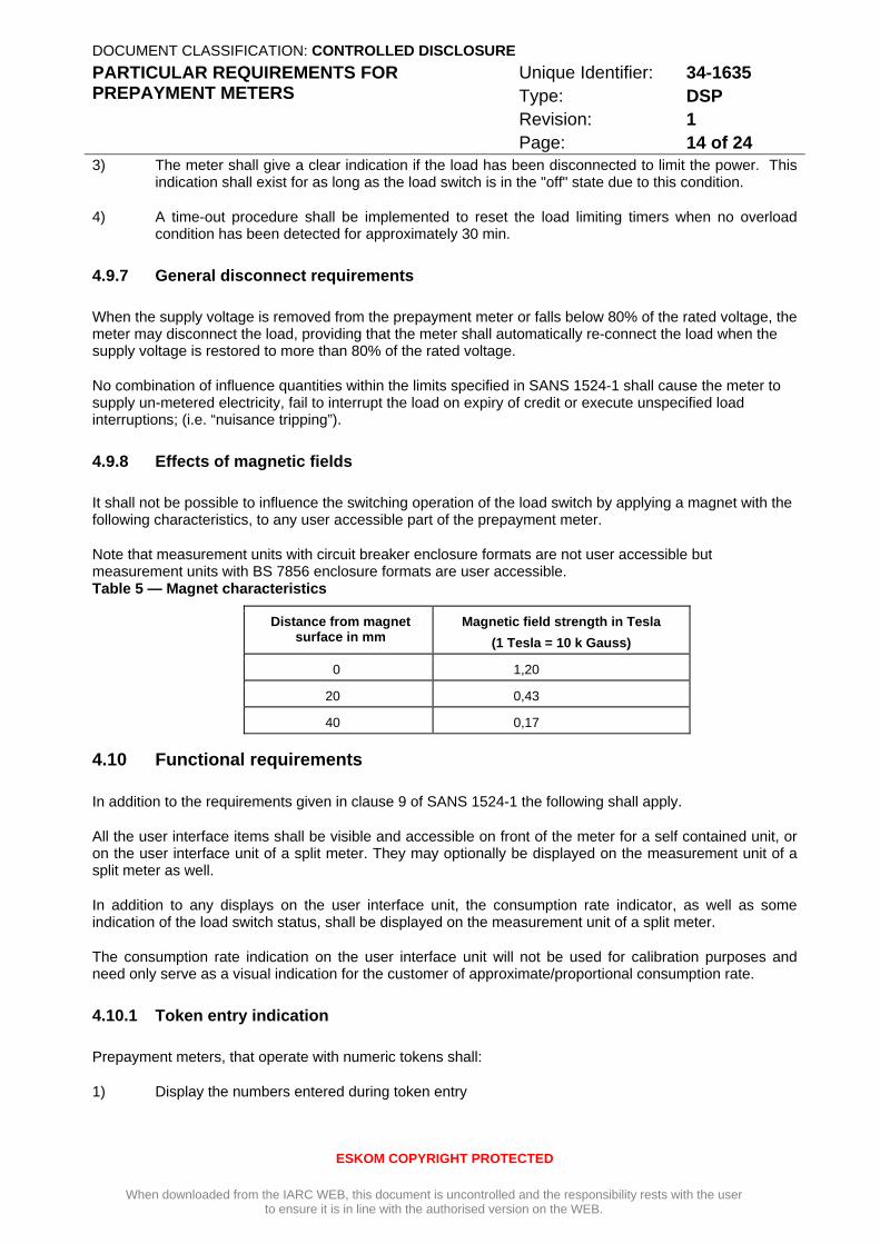
3) The meter shall give a clear indication if the load has been disconnected to limit the power. This indication shall exist for as long as the load switch is in the "off" state due to this condition.
4) A time-out procedure shall be implemented to reset the load limiting timers when no overload condition has been detected for approximately 30 min.
4.9.7 General disconnect requirements
When the supply voltage is removed from the prepayment meter or falls below 80% of the rated voltage, the meter may disconnect the load, providing that the meter shall automatically re-connect the load when the supply voltage is restored to more than 80% of the rated voltage.
No combination of influence quantities within the limits specified in SANS 1524-1 shall cause the meter to supply un-metered electricity, fail to interrupt the load on expiry of credit or execute unspecified load interruptions; (i.e. “nuisance tripping”).
4.9.8 Effects of magnetic fields
It shall not be possible to influence the switching operation of the load switch by applying a magnet with the following characteristics, to any user accessible part of the prepayment meter.
Note that measurement units with circuit breaker enclosure formats are not user accessible but measurement units with BS 7856 enclosure formats are user accessible. Table 5 — Magnet characteristics
Distance from magnet surface in mm
Magnetic field strength in Tesla (1 Tesla = 10 k Gauss)
0 1,20
20 0,43
40 0,17
4.10 Functional requirements
In addition to the requirements given in clause 9 of SANS 1524-1 the following shall apply.
All the user interface items shall be visible and accessible on front of the meter for a self contained unit, or on the user interface unit of a split meter. They may optionally be displayed on the measurement unit of a split meter as well.
In addition to any displays on the user interface unit, the consumption rate indicator, as well as some indication of the load switch status, shall be displayed on the measurement unit of a split meter.
The consumption rate indication on the user interface unit will not be used for calibration purposes and need only serve as a visual indication for the customer of approximate/proportional consumption rate.
4.10.1 Token entry indication
Prepayment meters, that operate with numeric tokens shall:
1) Display the numbers entered during token entry
DOCUMENT CLASSIFICATION: CONTROLLED DISCLOSURE PARTICULAR REQUIREMENTS FOR PREPAYMENT METERS
Unique Identifier: 34-1635 Type: DSP Revision: 1 Page: 15 of 24
ESKOM COPYRIGHT PROTECTED
When downloaded from the IARC WEB, this document is uncontrolled and the responsibility rests with the user to ensure it is in line with the authorised version on the WEB.
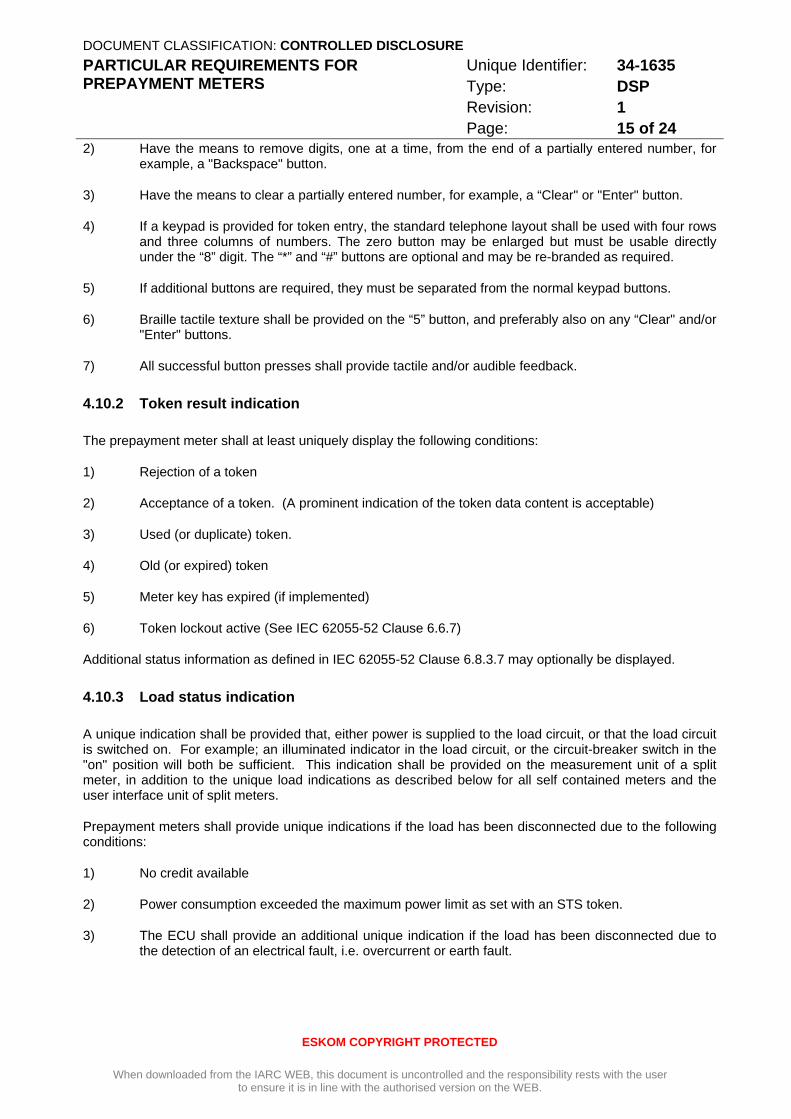
2) Have the means to remove digits, one at a time, from the end of a partially entered number, for example, a "Backspace" button.
3) Have the means to clear a partially entered number, for example, a “Clear" or "Enter" button.
4) If a keypad is provided for token entry, the standard telephone layout shall be used with four rows and three columns of numbers. The zero button may be enlarged but must be usable directly under the “8” digit. The “*” and “#” buttons are optional and may be re-branded as required.
5) If additional buttons are required, they must be separated from the normal keypad buttons.
6) Braille tactile texture shall be provided on the “5” button, and preferably also on any “Clear" and/or "Enter" buttons.
7) All successful button presses shall provide tactile and/or audible feedback.
4.10.2 Token result indication
The prepayment meter shall at least uniquely display the following conditions:
1) Rejection of a token
2) Acceptance of a token. (A prominent indication of the token data content is acceptable)
3) Used (or duplicate) token.
4) Old (or expired) token
5) Meter key has expired (if implemented)
6) Token lockout active (See IEC 62055-52 Clause 6.6.7)
Additional status information as defined in IEC 62055-52 Clause 6.8.3.7 may optionally be displayed.
4.10.3 Load status indication
A unique indication shall be provided that, either power is supplied to the load circuit, or that the load circuit is switched on. For example; an illuminated indicator in the load circuit, or the circuit-breaker switch in the "on" position will both be sufficient. This indication shall be provided on the measurement unit of a split meter, in addition to the unique load indications as described below for all self contained meters and the user interface unit of split meters.
Prepayment meters shall provide unique indications if the load has been disconnected due to the following conditions:
1) No credit available
2) Power consumption exceeded the maximum power limit as set with an STS token.
3) The ECU shall provide an additional unique indication if the load has been disconnected due to the detection of an electrical fault, i.e. overcurrent or earth fault.
DOCUMENT CLASSIFICATION: CONTROLLED DISCLOSURE PARTICULAR REQUIREMENTS FOR PREPAYMENT METERS
Unique Identifier: 34-1635 Type: DSP Revision: 1 Page: 16 of 24
ESKOM COPYRIGHT PROTECTED
When downloaded from the IARC WEB, this document is uncontrolled and the responsibility rests with the user to ensure it is in line with the authorised version on the WEB.
4.10.4 Power indicator
An obvious power indication shall be provided when power is supplied to the meter. An active display or regularly pulsed indicator (independent of any meter state, including 'no-load') shall be sufficient. This indication shall be provided on both the measurement unit and the user interface unit of split meters as well on all self contained meters.
4.10.5 Consumption rate indicator
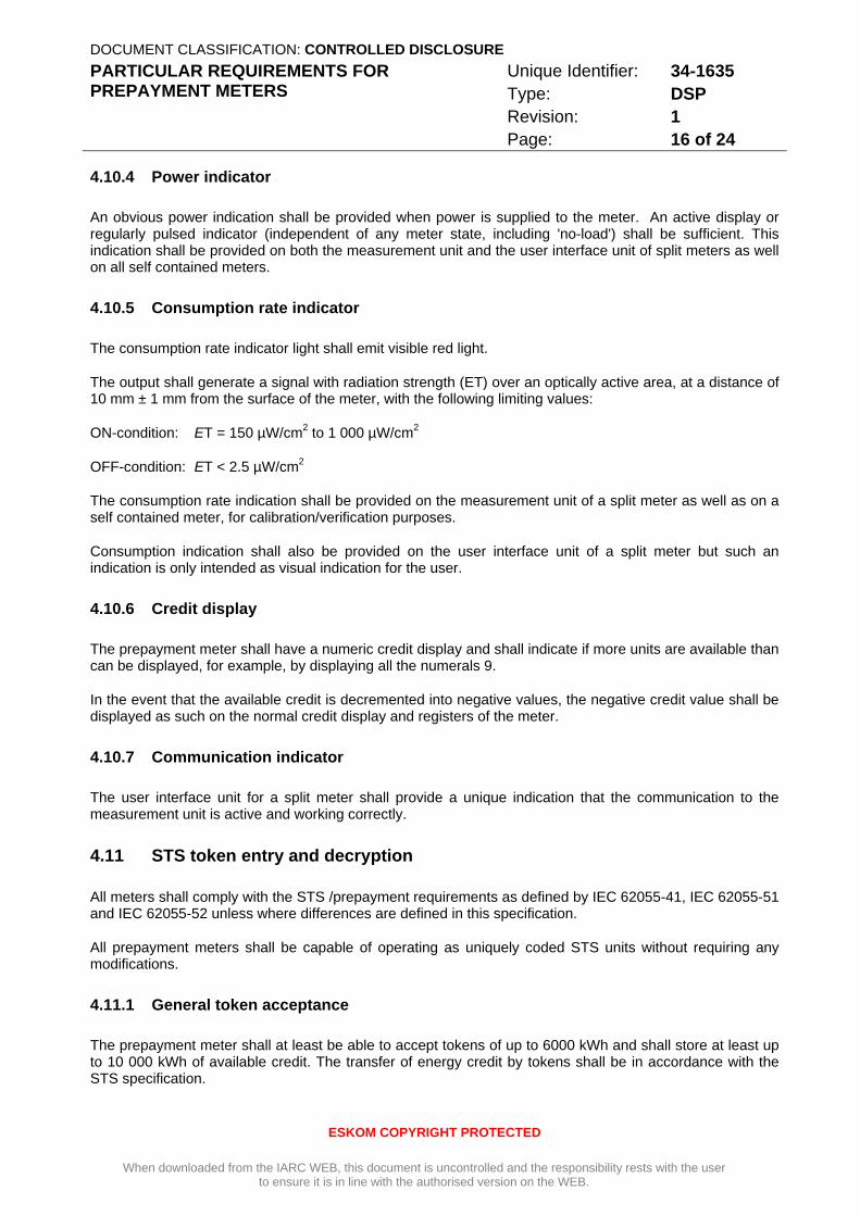
The consumption rate indicator light shall emit visible red light.
The output shall generate a signal with radiation strength (ET) over an optically active area, at a distance of 10 mm ± 1 mm from the surface of the meter, with the following limiting values:
ON-condition: ET = 150 µW/cm2 to 1 000 µW/cm2
OFF-condition: ET < 2.5 µW/cm2
The consumption rate indication shall be provided on the measurement unit of a split meter as well as on a self contained meter, for calibration/verification purposes.
Consumption indication shall also be provided on the user interface unit of a split meter but such an indication is only intended as visual indication for the user.
4.10.6 Credit display
The prepayment meter shall have a numeric credit display and shall indicate if more units are available than can be displayed, for example, by displaying all the numerals 9.
In the event that the available credit is decremented into negative values, the negative credit value shall be displayed as such on the normal credit display and registers of the meter.
4.10.7 Communication indicator
The user interface unit for a split meter shall provide a unique indication that the communication to the measurement unit is active and working correctly.
4.11 STS token entry and decryption
All meters shall comply with the STS /prepayment requirements as defined by IEC 62055-41, IEC 62055-51 and IEC 62055-52 unless where differences are defined in this specification.
All prepayment meters shall be capable of operating as uniquely coded STS units without requiring any modifications.
4.11.1 General token acceptance
The prepayment meter shall at least be able to accept tokens of up to 6000 kWh and shall store at least up to 10 000 kWh of available credit. The transfer of energy credit by tokens shall be in accordance with the STS specification.
DOCUMENT CLASSIFICATION: CONTROLLED DISCLOSURE PARTICULAR REQUIREMENTS FOR PREPAYMENT METERS
Unique Identifier: 34-1635 Type: DSP Revision: 1 Page: 17 of 24
ESKOM COPYRIGHT PROTECTED
When downloaded from the IARC WEB, this document is uncontrolled and the responsibility rests with the user to ensure it is in line with the authorised version on the WEB.
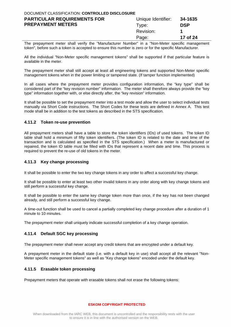
The prepayment meter shall verify the "Manufacturer Number" in a "Non-Meter specific management token", before such a token is accepted to ensure this number is zero or for the specific Manufacturer.
All the individual "Non-Meter specific management tokens" shall be supported if that particular feature is available in the meter.
The prepayment meter shall still accept at least all engineering tokens and supported Non-Meter specific management tokens when in the power limiting or tampered state. (If tamper function implemented)
In all cases where the prepayment meter provides configuration information, the “key type” shall be considered part of the “key revision number” information. The meter shall therefore always provide the “key type” information together with, or else directly after, the “key revision” information.
It shall be possible to set the prepayment meter into a test mode and allow the user to select individual tests manually via Short Code instructions. The Short Codes for these tests are defined in Annex A. This test mode shall be in addition to the test tokens as described in the STS specification.
4.11.2 Token re-use prevention
All prepayment meters shall have a table to store the token identifiers (IDs) of used tokens. The token ID table shall hold a minimum of fifty token identifiers. (The token ID is related to the date and time of the transaction and is calculated as specified in the STS specification.) When a meter is manufactured or repaired, the token ID table must be filled with IDs that represent a recent date and time. This process is required to prevent the re-use of old tokens in the meter.
4.11.3 Key change processing
It shall be possible to enter the two key change tokens in any order to affect a successful key change.
It shall be possible to enter at least two other invalid tokens in any order along with key change tokens and still perform a successful key change.
It shall be possible to enter the same key change token more than once, if the key has not been changed already, and still perform a successful key change.
A time-out function shall be used to cancel a partially completed key change procedure after a duration of 1 minute to 10 minutes.
The prepayment meter shall uniquely indicate successful completion of a key change operation.
4.11.4 Default SGC key processing
The prepayment meter shall never accept any credit tokens that are encrypted under a default key.
A prepayment meter in the default state (i.e. with a default key in use) shall accept all the relevant "Non-Meter specific management tokens" as well as "Key change tokens" encoded under the default key.
4.11.5 Erasable token processing
Prepayment meters that operate with erasable tokens shall not erase the following tokens:
DOCUMENT CLASSIFICATION: CONTROLLED DISCLOSURE PARTICULAR REQUIREMENTS FOR PREPAYMENT METERS
Unique Identifier: 34-1635 Type: DSP Revision: 1 Page: 18 of 24
ESKOM COPYRIGHT PROTECTED
When downloaded from the IARC WEB, this document is uncontrolled and the responsibility rests with the user to ensure it is in line with the authorised version on the WEB.
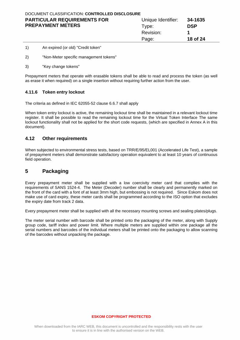
1) An expired (or old) "Credit token"
2) "Non-Meter specific management tokens"
3) "Key change tokens"
Prepayment meters that operate with erasable tokens shall be able to read and process the token (as well as erase it when required) on a single insertion without requiring further action from the user.
4.11.6 Token entry lockout
The criteria as defined in IEC 62055-52 clause 6.6.7 shall apply
When token entry lockout is active, the remaining lockout time shall be maintained in a relevant lockout time register. It shall be possible to read the remaining lockout time for the Virtual Token Interface The same lockout functionality shall not be applied for the short code requests, (which are specified in Annex A in this document).
4.12 Other requirements
When subjected to environmental stress tests, based on TRR/E/95/EL001 (Accelerated Life Test), a sample of prepayment meters shall demonstrate satisfactory operation equivalent to at least 10 years of continuous field operation.
5 Packaging
Every prepayment meter shall be supplied with a low coercivity meter card that complies with the requirements of SANS 1524-4. The Meter (Decoder) number shall be clearly and permanently marked on the front of the card with a font of at least 3mm high, but embossing is not required. Since Eskom does not make use of card expiry, these meter cards shall be programmed according to the ISO option that excludes the expiry date from track 2 data.
Every prepayment meter shall be supplied with all the necessary mounting screws and sealing plates/plugs.
The meter serial number with barcode shall be printed onto the packaging of the meter, along with Supply group code, tariff index and power limit. Where multiple meters are supplied within one package all the serial numbers and barcodes of the individual meters shall be printed onto the packaging to allow scanning of the barcodes without unpacking the package.
DOCUMENT CLASSIFICATION: CONTROLLED DISCLOSURE PARTICULAR REQUIREMENTS FOR PREPAYMENT METERS
Unique Identifier: 34-1635 Type: DSP Revision: 1 Page: 19 of 24
ESKOM COPYRIGHT PROTECTED
When downloaded from the IARC WEB, this document is uncontrolled and the responsibility rests with the user to ensure it is in line with the authorised version on the WEB.
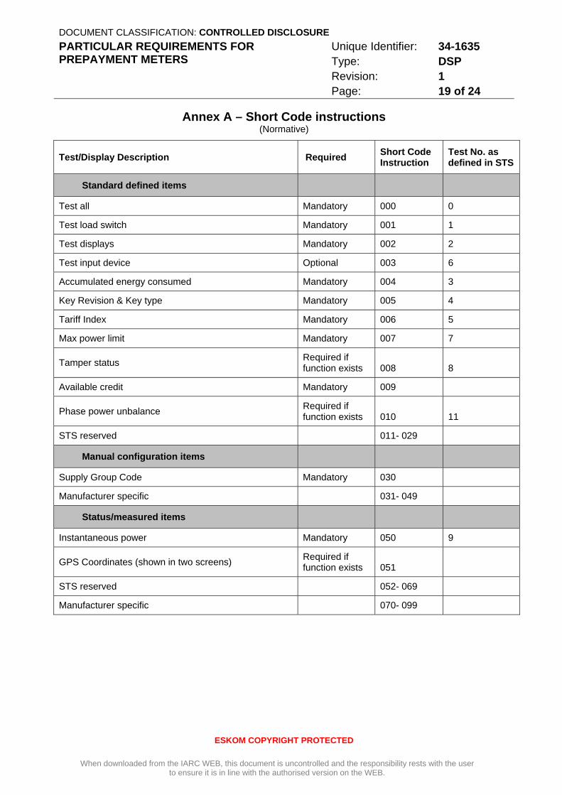
Annex A – Short Code instructions (Normative)
Test/Display Description Required Short Code Instruction
Test No. as defined in STS
Standard defined items
Test all Mandatory 000 0
Test load switch Mandatory 001 1
Test displays Mandatory 002 2
Test input device Optional 003 6
Accumulated energy consumed Mandatory 004 3
Key Revision & Key type Mandatory 005 4
Tariff Index Mandatory 006 5
Max power limit Mandatory 007 7
Tamper status Required if function exists 008 8
Available credit Mandatory 009
Phase power unbalance Required if function exists 010 11
STS reserved 011- 029
Manual configuration items
Supply Group Code Mandatory 030
Manufacturer specific 031- 049
Status/measured items
Instantaneous power Mandatory 050 9
GPS Coordinates (shown in two screens) Required if function exists 051
STS reserved 052- 069
Manufacturer specific 070- 099
DOCUMENT CLASSIFICATION: CONTROLLED DISCLOSURE PARTICULAR REQUIREMENTS FOR PREPAYMENT METERS
Unique Identifier: 34-1635 Type: DSP Revision: 1 Page: 20 of 24
ESKOM COPYRIGHT PROTECTED
When downloaded from the IARC WEB, this document is uncontrolled and the responsibility rests with the user to ensure it is in line with the authorised version on the WEB.
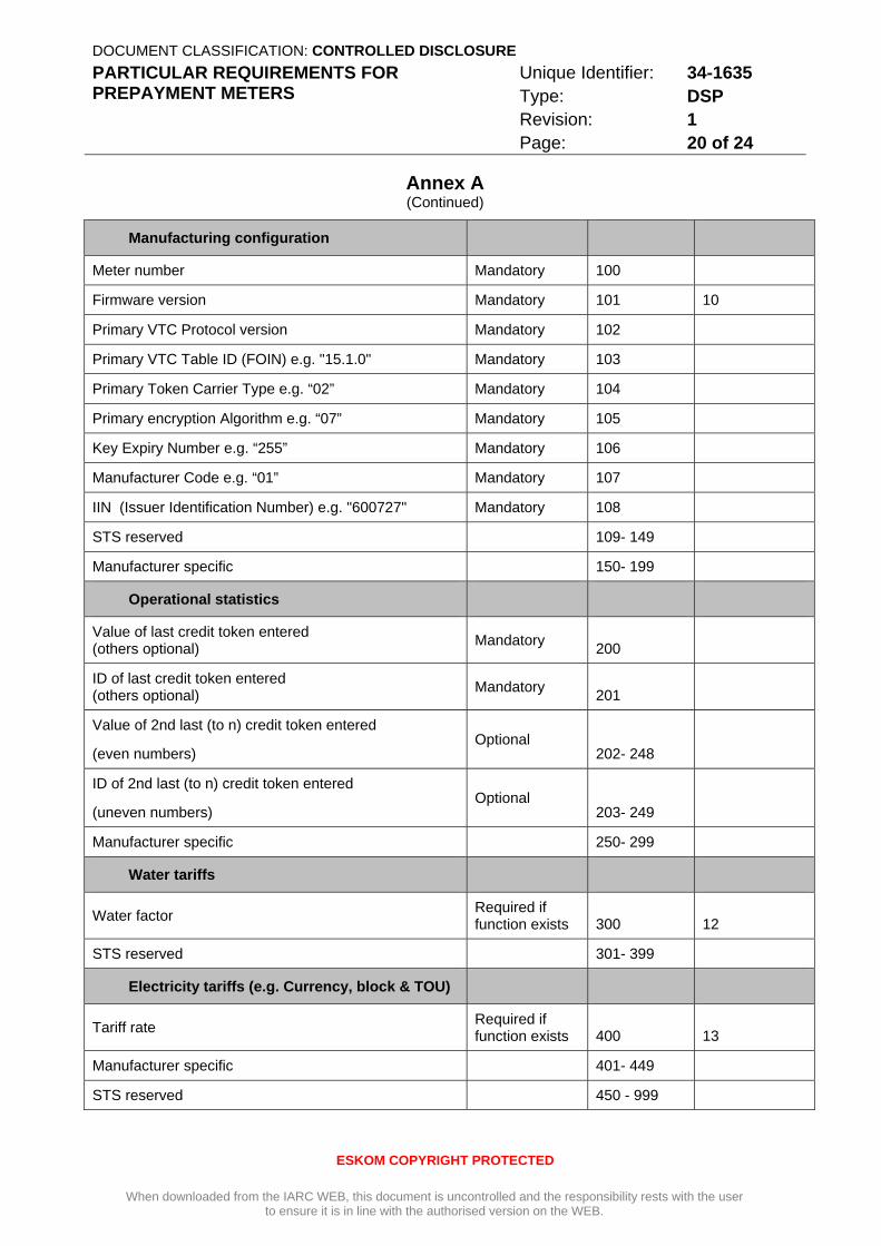
Annex A (Continued)
Manufacturing configuration
Meter number Mandatory 100
Firmware version Mandatory 101 10
Primary VTC Protocol version Mandatory 102
Primary VTC Table ID (FOIN) e.g. "15.1.0" Mandatory 103
Primary Token Carrier Type e.g. “02” Mandatory 104
Primary encryption Algorithm e.g. “07” Mandatory 105
Key Expiry Number e.g. “255” Mandatory 106
Manufacturer Code e.g. “01” Mandatory 107
IIN (Issuer Identification Number) e.g. "600727" Mandatory 108
STS reserved 109- 149
Manufacturer specific 150- 199
Operational statistics
Value of last credit token entered (others optional) Mandatory 200
ID of last credit token entered (others optional) Mandatory 201
Value of 2nd last (to n) credit token entered
(even numbers) Optional
202- 248
ID of 2nd last (to n) credit token entered
(uneven numbers) Optional
203- 249
Manufacturer specific 250- 299
Water tariffs
Water factor Required if function exists 300 12
STS reserved 301- 399
Electricity tariffs (e.g. Currency, block & TOU)
Tariff rate Required if function exists 400 13
Manufacturer specific 401- 449
STS reserved 450 - 999
DOCUMENT CLASSIFICATION: CONTROLLED DISCLOSURE PARTICULAR REQUIREMENTS FOR PREPAYMENT METERS
Unique Identifier: 34-1635 Type: DSP Revision: 1 Page: 21 of 24
ESKOM COPYRIGHT PROTECTED
When downloaded from the IARC WEB, this document is uncontrolled and the responsibility rests with the user to ensure it is in line with the authorised version on the WEB.
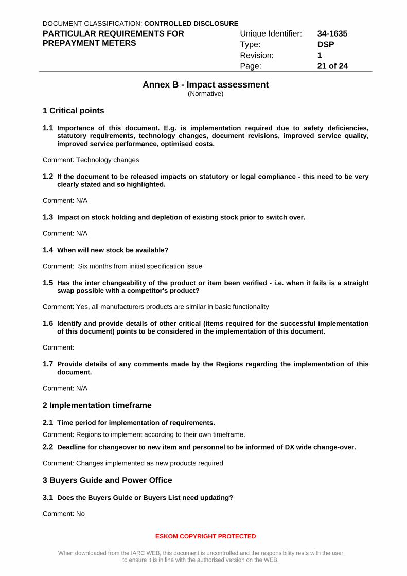
Annex B - Impact assessment (Normative)
1 Critical points
1.1 Importance of this document. E.g. is implementation required due to safety deficiencies, statutory requirements, technology changes, document revisions, improved service quality, improved service performance, optimised costs.
Comment: Technology changes
1.2 If the document to be released impacts on statutory or legal compliance - this need to be very clearly stated and so highlighted.
Comment: N/A
1.3 Impact on stock holding and depletion of existing stock prior to switch over.
Comment: N/A
1.4 When will new stock be available?
Comment: Six months from initial specification issue
1.5 Has the inter changeability of the product or item been verified - i.e. when it fails is a straight swap possible with a competitor's product?
Comment: Yes, all manufacturers products are similar in basic functionality
1.6 Identify and provide details of other critical (items required for the successful implementation of this document) points to be considered in the implementation of this document.
Comment:
1.7 Provide details of any comments made by the Regions regarding the implementation of this document.
Comment: N/A
2 Implementation timeframe
2.1 Time period for implementation of requirements.
Comment: Regions to implement according to their own timeframe.
2.2 Deadline for changeover to new item and personnel to be informed of DX wide change-over.
Comment: Changes implemented as new products required
3 Buyers Guide and Power Office
3.1 Does the Buyers Guide or Buyers List need updating?
Comment: No
DOCUMENT CLASSIFICATION: CONTROLLED DISCLOSURE PARTICULAR REQUIREMENTS FOR PREPAYMENT METERS
Unique Identifier: 34-1635 Type: DSP Revision: 1 Page: 22 of 24
ESKOM COPYRIGHT PROTECTED
When downloaded from the IARC WEB, this document is uncontrolled and the responsibility rests with the user to ensure it is in line with the authorised version on the WEB.
Annex B (Continued)
3.2 What Buyer’s Guides or items have been created?
Comment: Buyers Guides remain the same as for existing products
3.3 List all assembly drawing changes that have been revised in conjunction with this document.
Comment: N/A
3.4 If the implementation of this document requires assessment by CAP, provide details under 5
3.5 Which Power Office packages have been created, modified or removed?
Comment: N/A
4 CAP / LAP Pre-Qualification Process related impacts
4.1 Is an ad-hoc re-evaluation of all currently accepted suppliers required as a result of implementation of this document?
Comment: Yes
4.2 If NO, provide motivation for issuing this specification before Acceptance Cycle Expiry date.
Comment: N/A
4.3 Are ALL suppliers (currently accepted per LAP), aware of the nature of changes contained in this document?
Comment: No, will be done during implementation
4.4 Is implementation of the provisions of this document required during the current supplier qualification period?
Comment: Yes
4.5 If Yes to 4.4, what date has been set for all currently accepted suppliers to comply fully?
Comment: This will be implemented through the CAP process
4.6 If Yes to 4.4, have all currently accepted suppliers been sent a prior formal notification informing them of Eskom’s expectations, including the implementation date deadline?
Comment: This will be implemented through the CAP process
4.7 Can the changes made, potentially impact upon the purchase price of the material/equipment?
Comment: Yes
4.8 Material group(s) affected by specification: (Refer to Pre-Qualification invitation schedule for list of material groups)
Comment: Prepayment

DOCUMENT CLASSIFICATION: CONTROLLED DISCLOSURE PARTICULAR REQUIREMENTS FOR PREPAYMENT METERS
Unique Identifier: 34-1635 Type: DSP Revision: 1 Page: 23 of 24
ESKOM COPYRIGHT PROTECTED
When downloaded from the IARC WEB, this document is uncontrolled and the responsibility rests with the user to ensure it is in line with the authorised version on the WEB.
Annex B (Continued)
5 Training or communication
5.1 Is training required?
Comment: No
5.2 State the level of training required to implement this document. (E.g. awareness training, practical / on job, module, etc.)
Comment: N/A
5.3 State designations of personnel that will require training.
Comment: N/A
5.4 Is the training material available? Identify person responsible for the development of training material.
Comment: N/A
5.5 If applicable, provide details of training that will take place. (E.G. sponsor, costs, trainer, schedule of training, course material availability, training in erection / use of new equipment, maintenance training, etc).
Comment: N/A
5.6 Was Technical Training Section consulted w.r.t module development process?
Comment: N/A
5.7 State communications channels to be used to inform target audience.
Comment: N/A
6 Special tools, equipment, software
6.1 What special tools, equipment, software, etc will need to be purchased by the Region to effectively implement?
Comment: None
6.2 Are there stock numbers available for the new equipment?
Comment: Yes
6.3 What will be the costs of these special tools, equipment, software?
Comment: N/A.
DOCUMENT CLASSIFICATION: CONTROLLED DISCLOSURE PARTICULAR REQUIREMENTS FOR PREPAYMENT METERS
Unique Identifier: 34-1635 Type: DSP Revision: 1 Page: 24 of 24
ESKOM COPYRIGHT PROTECTED
When downloaded from the IARC WEB, this document is uncontrolled and the responsibility rests with the user to ensure it is in line with the authorised version on the WEB.
Annex B (Continued)
7 Finances
7.1 What total costs would the Regions be required to incur in implementing this document? Identify all cost activities associated with implementation, e.g. labour, training, tooling, stock, obsolescence
Comment: Prices for split meters will be higher as well as labour for installation.
……………………………………………………………………………………………………………………….
……………………………………………………………………………………………………………………….
……………………………………………………………………………………………………………………….
Impact assessment completed by:
Name: J. O’Kennedy
Designation: Chief Engineer, IARC Control Technologies (prepayment)