unit-1 - chettinadtech.ac.inchettinadtech.ac.in/storage/11-12-30/11-12-30-14-16-08-1246... · g(t)...
TRANSCRIPT

UNIT-1
Syllabus
UNIT 1 - INTRODUCTION
Basic representation of communication system – Transmitter- Channel- Noise and
Receiver-Base band and band pass signal- Transmission media- bandwidth and
capacity-Electromagnetic spectrum- Bandwidth requirements- Spectra of sinusoidal
and non sinusoidal waves- Analog versus digital communication
____________________________________________________________________
CONTENTS:
Introduction
Model of Communication systems
Hybrid Communication Systems
Types of Communication systems
Basic representation of communication system
Electromagnetic spectrum
Bandwidth requirements
Analog versus digital communication
History of communication systems
INTRODUCTION
Communication System:
In telecommunication, a communications system is a collection of individual
communications networks, transmission systems, relay stations, tributary stations,
and data terminal equipment (DTE) usually capable of interconnection and
interoperation to form an integrated whole. The components of a communications
system serve a common purpose, are technically compatible, use common
procedures, respond to controls, and operate in unison. Telecommunications is a
method of communication (e.g., for sports broadcasting, mass media, journalism,…)

A communications subsystem is a functional unit or operational assembly that
is smaller than the larger assembly under consideration. Communication subsystem
basically consists of a receiver, frequency translator and a transmitter. It also contains
transponders and other transponders in it and communication satellite
communication system receives signals from the antenna subsystem.
Signal
Communications is invariably about sending information from one side to
another.
Information may be text, data, or signals.
A signal may be defined as any physical quantity that varies with time, space,
or any other variable(s).
Some signals can be described by `tractable' expressions. For example, a
Sinusoidal signal:
m(t) = sin(mt)
Carrier Modulation
Base band communications often refers to information transmission over
wirelines; e.g., telephone lines, and coaxial cables.
In baseband transmissions, low frequency regions are used.
In wireless transmissions such as radio, TV, mobile comm. & satellite comm.,
modulation (or carrier modulation) is required.
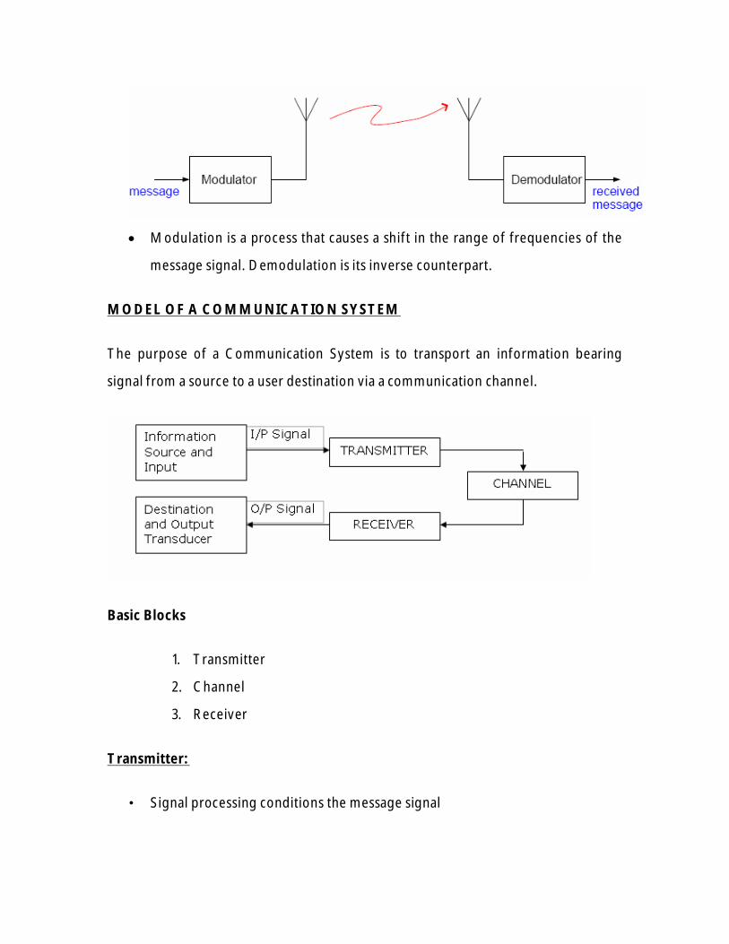
Modulation is a process that causes a shift in the range of frequencies of the
message signal. Demodulation is its inverse counterpart.
MODEL OF A COMMUNICATION SYSTEM
The purpose of a Communication System is to transport an information bearing
signal from a source to a user destination via a communication channel.
Basic Blocks
1. Transmitter
2. Channel
3. Receiver
Transmitter:
• Signal processing conditions the message signal

– Lowpass filtering to make sure that the message signal occupies a
specific bandwidth, e.g. in AM and FM radio, each station is assigned a
slot in the frequency domain.
– In a digital communications system, we might add redundancy to the
input bit stream
• Carrier circuits
– Convert baseband signal into a frequency band appropriate for the
channel
– Uses analog and/or digital modulation
Channel
• Transmission media:
– Wireline (twisted pair, coaxial, fiber optics)
– Wireless (indoor/air, outdoor/air, underwater, space)
• Propagating signals experience a gradual degradation over distance
• Boosting improves signal and reduces noise, e.g. repeaters
TRANSMITTERS AND RECEIVERS
Generalized Transmitters
– Transmitters generate the modulated signal at the carrier frequency fc
, from the modulating signal m(t).
– Any type of modulated signal could be represented by

g(t) is a function of the modulating signal m(t) .
The particular relationship that is chosen for g(t) in terms of m(t) defines
the type of modulation that is used, such as AM, SSB, or FM.
Generalized Receiver
• The receiver has the job of extracting the source information from the
received modulated signal that may be corrupted by noise.
• Often, it is desired that the receiver output be a replica of the modulating
signal that was present at the transmitter input.
• There are two main classes of receivers:
1. The Tuned Radio-Frequency (TRF) receiver and
2. The Superheterodyne receiver.
• Most receivers employ the Superheterodyne receiving technique.
Receiver Parameters
• Sensitivity
– The voltage that must be applied to the Rx I/P to give a standard O/P
• Selectivity
– Ability of the receiver to reject adjacent unwanted signals
• Image Frequency Rejection
– Rejection of the frequency which would generate the same IF when
mixed with the LO frequency fsi=fs+2fi = fo+fi
)( : PM
)](1[ : AM
g(m) Modulation of Type
tmjDc
c
peA
tmA

Wire line Channel Impairments
• Attenuation: linear distortion that is dependent on the frequency response
of the channel.
• Spreading: the finite extent of each transmitted pulse increases, i.e. pulse
widens due to
– Transmit pulse length T s
– Channel impulse response length T h
– Resulting waveform due to convolution has duration T s + T h
• Phase jitter: the same sinusoid experiences different phase shifts in the
channel
• Additive noise: arises from many sources in the transmitter, channel, and
receiver
• Same as wire line channel impairments plus others
• Fading: multiplicative noise
– Example: talking on a cellular phone while driving a car when the
reception fades in and out
• Multiple propagation paths
– Multiple ways for transmitted signal to arrive at receiver
Receiver and Information Sinks
• Receiver
– Carrier circuits undo effects of carrier circuits in transmitter, e.g.
demodulate from a bandpass signal to a baseband signal
– Signal processing subsystem extracts and enhances the baseband
signal
• Information sinks
– Output devices such as computer screens, speakers,and TV screens
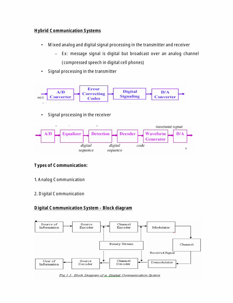
Hybrid Communication Systems
• Mixed analog and digital signal processing in the transmitter and receiver
– Ex: message signal is digital but broadcast over an analog channel
(compressed speech in digital cell phones)
• Signal processing in the transmitter
• Signal processing in the receiver
Types of Communication:
1. Analog Communication
2. Digital Communication
Digital Communication System - Block diagram
Digital Communication- Blocks
• Information Source
• Source Encoder and Decoder
• Channel Encoder and Decoder
• Modulator and Demodulator
• Channel
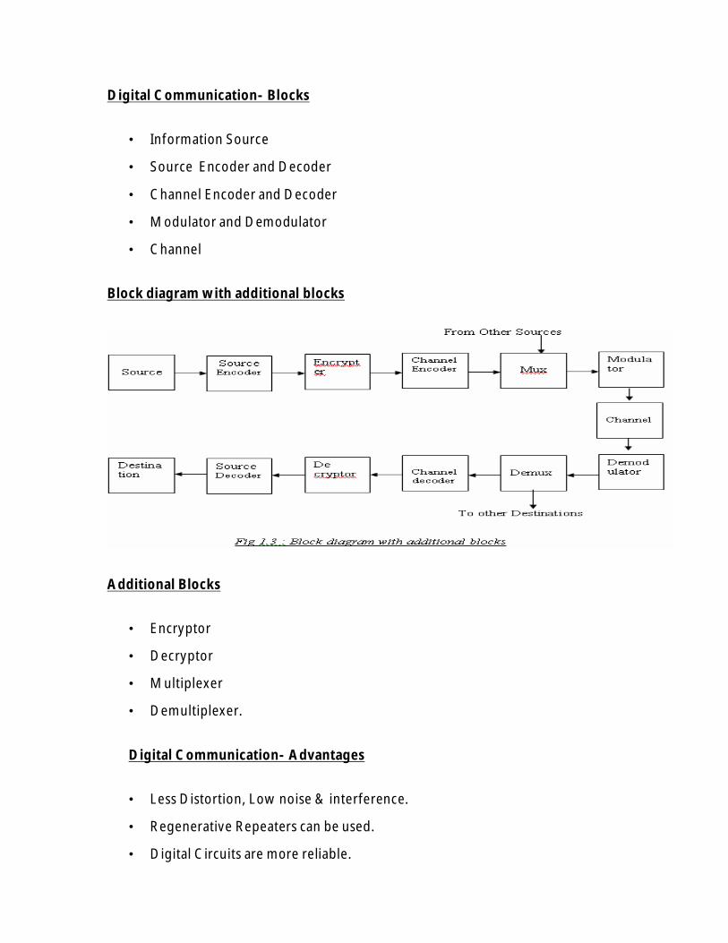
Block diagram with additional blocks
Additional Blocks
• Encryptor
• Decryptor
• Multiplexer
• Demultiplexer.
Digital Communication- Advantages
• Less Distortion, Low noise & interference.
• Regenerative Repeaters can be used.
• Digital Circuits are more reliable.

• Hardware implementation is more flexible.
• Secrecy of information.
• Low probability of error due to error detection and error correction.
• Multiplexing- ( TDM )
• Signal Jamming is avoided.
Digital Communication- Disadvantages
• Large Bandwidth
• Synchronization
Channels for Digital Communication
Channel Characteristics:
Bandwidth
Power
Linear or Non-linear
External interference
Types of Channels
1. Telephone Channels
2. Coaxial Cables
3. Optical fibers
4. Microwave radio
5. Satellite Channel
1. Telephone Channels
Provides voice grade Communication.
Good for data communication over long distances.
Frequency range: 300Hz – 3400Hz.

High SNR – about 30dB.
Flat amplitude response for voice signals.
For data & image transmissions EQUALIZERS are used.
Transmission rate = 16.8kb/s
2. Coaxial Cable
Single-wire conductor inside an outer Conductor with dielectric
between them.
Wide Bandwidth
Low external Interference.
Closely spaced Repeaters are required.
Transmission rate = 274 Mb/s.
3. Optical fibers
Communication is by light rays.
Fiber consists of Inner core and an outer core called CLADDING.
Refractive Index of Cladding is less.
Larger Bandwidth.
Immune to cross talk and EMI.
More secure.
Low cost.
Date rate = Terra bits/sec.
4. Microwave radio
Transmitter & Receiver With antennas.
Works on Line-of-sight principle.
Point to Multipoint communication.
Reliable & High Speed of Transmission.
Operating Frequency - (1 – 30)GHz
System Performance degrades due to meteorological variations.
5. Satellite Channel.
Repeater in the sky.

Placed in geo-stationary orbit.
Long distance transmission.
High Bandwidth.
Operates in microwave frequency.
Uplink frequency is more than down link frequency
Why Modulate?
Reduce noise and interference.
Channel assignment.
Multiplexing or transmission of several messages over a single channel.
Overcome equipment limitation.
Why Digital Communication?
Inexpensive digital circuits may be used.
Privacy by using data encryption.
Greater dynamic range.
In long-distance systems, noise does not accumulate from repeater to
repeater.
Errors may be corrected.
Base band and band pass signals
• Baseband: refers to the signals and systems before modulation,
which have frequencies/bandwidth much lower than the
carrier frequency
• Passband: refers to the signals and systems after (including)
modulation, which have frequencies/bandwidth around the
carrier frequency
• Baseband signal: is usually the message signal

• Passband signal: is usually the modulated signal, or transmitted
signal
• Base band signal is the original signal having the original
frequencies when delivered by transmitters.
• In base band communication, signals are transmitted without
modulation.
• Band pass signal is a signal which is modulated by one of the
modulation schemes.
• Demodulation is the process of extracting the baseband
message from the carrier so that it may be processed and
interpreted by the intended receiver
MODULATION TECHNIQUES:

l List of modulation methods
– Amplitude modulation methods and applications
1. AM (amplitude modulation): AM radio, short wave radio
broadcast, CB radio
2. DSBSC (double sideband suppressed carrier AM): data
modem, Color TV’s color signals
3. SSB (single sideband AM): telephone
4. VSB (vestigial sideband AM): TV picture signal
Angle modulation methods and applications
1. FM (frequency modulation): FM radio broadcast, TV sound
signal, analog cellular phone
2. PM (phase modulation): not widely used, except in digital
communication systems (but that is different)
Electromagnetic spectrum:
The electromagnetic spectrum is the range of all possible frequencies of
electromagnetic radiation. The "electromagnetic spectrum" of an object is the
characteristic distribution of electromagnetic radiation emitted or absorbed by that
particular object.
The electromagnetic spectrum extends from below frequencies used for modern
radio through to gamma radiation at the short-wavelength end, covering
wavelengths from thousands of kilometers down to a fraction of the size of an atom.
The long wavelength limit is the size of the universe itself, while it is thought that
the short wavelength limit is in the vicinity of the Planck length, although in principle
the spectrum is infinite and continuous.

Range of the spectrum
EM waves are typically described by any of the following three physical properties:
the frequency f, wavelength λ, or photon energy E. Frequencies range from 2.4x10²³
Hz (1 GeV gamma rays) down to tiny fractions of Hertz (nanohertz for astronomical
scale waves). Wavelength is inversely proportional to the wave frequency, so
gamma rays have very short wavelengths that are fractions of the size of atoms,
whereas wavelengths can be as long as the universe. Photon energy is directly
proportional to the wave frequency, so gamma rays have the highest energy around
a billion electron volts and radio waves have very low energy around femto electron
volts. These relations are illustrated by the following equations:
Where:
c = 299,792,458 m/s (speed of light in vacuum) and
h = 6.62606896(33)×10−34 J·s (Planck's constant).
Whenever electromagnetic waves exist in a medium (matter), their wavelength is
decreased. Wavelengths of electromagnetic radiation, no matter what medium they
are traveling through, are usually quoted in terms of the vacuum wavelength,
although this is not always explicitly stated.
Generally, EM radiation is classified by wavelength into radio wave, microwave,
infrared, the visible region we perceive as light, ultraviolet, X-rays and gamma rays.
The behavior of EM radiation depends on its wavelength. When EM radiation
interacts with single atoms and molecules, its behavior also depends on the amount
of energy per quantum (photon) it carries. Electromagnetic radiation can also be
divided into octaves, as sound waves are.

Spectroscopy can detect a much wider region of the EM spectrum than the visible
range of 400 nm to 700 nm. A common laboratory spectroscope can detect
wavelengths from 2 nm to 2500 nm. Detailed information about the physical
properties of objects, gases, or even stars can be obtained from this type of device.
Spectroscopes are widely used in astrophysics. For example, many hydrogen atoms
emit a radio wave photon which has a wavelength of 21.12 cm. Also, frequencies of
30 Hz and below can be produced by and are important in the study of certain stellar
nebulae and frequencies as high as 2.9×1027 Hz have been detected from
astrophysical sources.
Bandwidth:
Bandwidth is the information-carrying capacity of a communication channel. The
channel may be analog or digital. Analog transmissions such as telephone calls, AM
and FM radio, and television are measured in cycles per second (hertz or Hz). Digital
transmissions are measured in bits per second. For digital systems, the terms
"bandwidth" and "capacity" are often used interchangeably, and the actual
transmission capabilities are referred to as the data transfer rate (or just data rate).
Bandwidth Requirements and Ratings
In the United States, the Federal Communications Commission (FCC) is in charge of
allocating the electromagnetic spectrum and, thus, the bandwidth of various
communication systems. In the electromagnetic spectrum, sound waves occupy low
ranges, while microwaves, visible light, ultraviolet, and X-rays occupy upper ranges.
The bandwidths occupied by various communication technologies are described in
"Electromagnetic Spectrum."

The bandwidth requirements of various applications are listed in Table Bandwidth-1.
The rates are shown in bits/sec (bits per second), Kbits/sec (thousands of bits per
second), Mbits/sec (millions of bits per second), and Gbits/sec (billions of bits per
second). Compression and other techniques can reduce these requirements.
Application Rate
Personal communications 300 to 9,600 bits/sec or higher
E-mail transmissions 2,400 to 9,600 bits/sec or higher
Remote control programs 9,600 bits/sec to 56 Kbits/sec
Digitized voice phone call 64,000 bits/sec
Database text query Up to 1 Mbit/sec
Digital audio 1 to 2 Mbits/sec
Access images 1 to 8 Mbits/sec
Compressed video 2 to 10 Mbits/sec
Medical transmissions Up to 50 Mbits/sec
Document imaging 10 to 100 Mbits/sec
Scientific imaging Up to 1 Gbit/sec
Full-motion video 1 to 2 Gbits/sec
Table Bandwidth-1: Bandwidth requirements for various applications
The transmission rates of various communication systems are listed in Table
Bandwidth-2. Compression techniques and signal encoding are used to boost data

rates. For example, modems use the ITU V.42 bis data compression standard to
compress data at a ratio of over 3 to 1. V.42 bis compresses and decompresses on the
fly as data is sent and received by connected modems.
Type Rate
Dial-up modem connection 1,200 bits/sec to 56 Kbits/sec
Serial port file transfers 2,000 bits/sec
ISDN (Integrated Services Digital
Network)
64 Kbits/sec or 128 Kbits/sec
Fractional T1 digital WAN link 64 Kbits/sec
Parallel port 300 Kbits/sec
DirecPC (satellite) Internet downloads 400 Kbits/sec
DSL (Digital Subscriber Line) 512 Kbits/sec to 8 Mbits/sec
Cable (CATV) modems 512 Kbits/sec to 10 Mbits/sec (or
higher)
T1 digital WAN link 1.544 Mbits/sec
ARCNET LANs 2.5 or 20 Mbits/sec
Token ring LANs 4 or 16 Mbits/sec
Ethernet LANs 10, 100, 1,000 Mbits/sec
T3 digital WAN link 44.184 Mbits/sec
HSSI (High-Speed Serial Interface) 52 Mbits/sec

FDDI (Fiber Distributed Data Interface) 100 Mbits/sec
Fibre Channel 1 Gbit/sec
Gigabit Ethernet 1 Gbit/sec
10GE (10 Gigabit Ethernet) 10 Gbits/sec
SONET (Synchronous Optical Network) 51.9 Mbits/sec to 2.5 Gbits/sec
Optical (lambda) networks implementing
DWDM
Hundreds (or perhaps thousands) of
lambdas per fiber, each running at 2.5
Gbits/sec
Table Bandwidth-2: Transmission rates of various communication systems

γ= Gamma rays MIR= Mid infrared HF= High freq.
HX= Hard X-Rays FIR= Far infrared MF= Medium freq.
SX= Soft X-Rays Radio waves LF= Low freq.
EUV= Extreme ultraviolet EHF= Extremely high freq. VLF= Very low freq.
NUV= Near ultraviolet SHF= Super high freq. VF/ULF= Voice freq.
Visible light UHF= Ultra high freq. SLF= Super low freq.
NIR= Near Infrared VHF= Very high freq. ELF= Extremely low freq.
Freq=Frequency
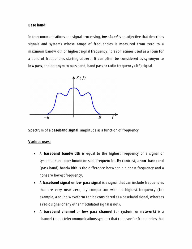
Base band:
In telecommunications and signal processing, baseband is an adjective that describes
signals and systems whose range of frequencies is measured from zero to a
maximum bandwidth or highest signal frequency; it is sometimes used as a noun for
a band of frequencies starting at zero. It can often be considered as synonym to
lowpass, and antonym to pass band, band pass or radio frequency (RF) signal.
Spectrum of a baseband signal, amplitude as a function of frequency
Various uses:
A baseband bandwidth is equal to the highest frequency of a signal or
system, or an upper bound on such frequencies. By contrast, a non-baseband
(pass band) bandwidth is the difference between a highest frequency and a
nonzero lowest frequency.
A baseband signal or low pass signal is a signal that can include frequencies
that are very near zero, by comparison with its highest frequency (for
example, a sound waveform can be considered as a baseband signal, whereas
a radio signal or any other modulated signal is not).
A baseband channel or low pass channel (or system, or network) is a
channel (e.g. a telecommunications system) that can transfer frequencies that

are very near zero. Examples are serial cables and local area networks
(LANs).
Baseband modulation, also known as line coding, aims at transferring a
digital bit stream over a baseband channel, as an alternative to carrier-
modulated approaches.
An equivalent baseband signal or equivalent lowpass signal is – in analog
and digital modulation methods with constant carrier frequency (for example
ASK, PSK and QAM, but not FSK) – a complex valued representation of the
modulated physical signal (the so called pass band signal or RF signal). The
equivalent baseband signal is , where I(t) is the
inphase signal, Q(t) the quadrature phase signal, and j the imaginary unit. In a
digital modulation method, the I(t) and Q(t) signals of each modulation
symbol are evident from the constellation diagram. The frequency spectrum
of this signal includes negative as well as positive frequencies. The physical
passband signal corresponds to
where ω is the carrier angular frequency in rad/s.
In an equivalent baseband model of a communication system, the
modulated signal is replaced by a complex valued equivalent baseband signal
with carrier frequency of 0 hertz, and the RF channel is replaced by an
equivalent baseband channel model where the frequency response is
transferred to baseband frequencies.
A signal "at baseband" is usually considered to include frequencies from near
0 Hz up to the highest frequency in the signal with significant power.
In general, signals can be described as including a whole range of different
frequencies added together. In telecommunications in particular, it is often the case

that those parts of the signal which are at low frequencies are 'copied' up to higher
frequencies for transmission purposes, since there are few communications media
that will pass low frequencies without distortion. Then, the original, low frequency
components are referred to as the baseband signal. Typically, the new, high-
frequency copy is referred to as the 'RF' (radio-frequency) signal.
The concept of baseband signals is most often applied to real-valued signals, and
systems that handle real-valued signals. Fourier analysis of such signals includes a
negative-frequency band, but the negative-frequency information is just a mirror of
the positive-frequency information, not new information. For complex-valued
signals, on the other hand, the negative frequencies carry new information. In that
case, the full two-sided bandwidth is generally quoted, rather than just the half
measured from zero; the concept of baseband can be applied by treating the real and
imaginary parts of the complex-valued signal as two different real signals.
Baseband vs passband transmission in Ethernet and other network access
technology
The word "BASE" in Ethernet physical layer standards, for example 10BASE5,
100BASE-T and 1000BASE-SX, implies baseband digital transmission, i.e that a line
code is used, and that an unfiltered wire (i.e. a low-pass transmission channel) is
used. This is as opposed to 10PASS-TS Ethernet, where "PASS" implies passband
transmission. Passband transmission makes communication possible over a passband
filtered channel such as the telephone network local-loop or a wireless channel.
Passband digital transmission requires a digital modulation scheme, often provided
by modem equipment. In the 10PASS-TS case the VDSL standard is utilized, which is
based on the Discrete multi-tone modulation (DMT) scheme. Other examples of
passband transmission are wireless networks and cable modems.

Modulation
A signal at baseband is often used to modulate a higher frequency carrier wave in
order that it may be transmitted via radio. Modulation results in shifting the signal up
to much higher frequencies (radio frequencies, or RF) than it originally spanned. A
key consequence of the usual double-sideband amplitude modulation (AM) is that,
usually, the range of frequencies the signal spans (its spectral bandwidth) is
doubled. Thus, the RF bandwidth of a signal (measured from the lowest frequency
as opposed to 0 Hz) is usually twice its baseband bandwidth. Steps may be taken to
reduce this effect, such as single-sideband modulation; the highest frequency of
such signals greatly exceeds the baseband bandwidth.
Some signals can be treated as baseband or not, depending on the situation. For
example, a switched analog connection in the telephone network has energy below
300 Hz and above 3400 Hz removed by band pass filtering; since the signal has no
energy very close to zero frequency, it may not be considered a baseband signal, but
in the telephone systems frequency-division multiplexing hierarchy, it is usually
treated as a baseband signal, by comparison with the modulated signals used for
long-distance transmission. The 300 Hz lower band edge in this case is treated as
"near zero", being a small fraction of the upper band edge.
The figure shows what happens with AM modulation:
Comparison of the equivalent baseband version of a signal and its AM-modulated
(double-sideband) RF version, showing the typical doubling of the occupied
bandwidth.
The simplest definition is that a signal's baseband bandwidth is its bandwidth before
modulation and multiplexing, or after demultiplexing and demodulation.
The composite video signal created by devices such as most newer VCRs, game consoles
and DVD players is a commonly used baseband signal.
Analog Vs Digital Communication:
Analog Communication:
� A physical quantity that varies with “time”, usually in a smooth or continuous
fashion.
� Fidelity describes how close the received signal to the original signal is. Fidelity
defines acceptability.
Digital Communication:
� An ordered sequence of symbols selected from a finite set of discrete elements.
� When digital signals are sent through a communication system, degree of
accuracy within a given time defines the acceptability.
Analog communication systems, amplitude modulation (AM) radio being a typifying
example, can inexpensively communicate a band limited analog signal from one
location to another (point-to-point communication) or from one point to many
(broadcast). Although it is not shown here, the coherent receiver provides the
largest possible signal-to-noise ratio for the demodulated message. An analysis of
this receiver thus indicates that some residual error will always be present in an
analog system's output.

Although analog systems are less expensive in many cases than digital ones for the
same application, digital systems offer much more efficiency, better performance,
and much greater flexibility.
Efficiency: The Source Coding Theorem allows quantification of just how
complex a given message source is and allows us to exploit that complexity by
source coding (compression). In analog communication, the only parameters
of interest are message bandwidth and amplitude. We cannot exploit signal
structure to achieve a more efficient communication system.
Performance: Because of the Noisy Channel Coding Theorem, we have a
specific criterion by which to formulate error-correcting codes that can bring
us as close to error-free transmission as we might want. Even though we may
send information by way of a noisy channel, digital schemes are capable of
error-free transmission while analog ones cannot overcome channel
disturbances.
Flexibility: Digital communication systems can transmit real-valued discrete-
time signals, which could be analog ones obtained by analog-to-digital
conversion, and symbolic-valued ones (computer data, for example). Any
signal that can be transmitted by analog means can be sent by digital means,
with the only issue being the number of bits used in A/D conversion (how
accurately do we need to represent signal amplitude). Images can be sent by
analog means (commercial television), but better communication
performance occurs when we use digital systems (HDTV). In addition to
digital communication's ability to transmit a wider variety of signals than
analog systems, point-to-point digital systems can be organized into global
(and beyond as well) systems that provide efficient and flexible information
transmission. Computer networks, explored in the next section, are what we
call such systems today. Even analog-based networks, such as the telephone

system, employ modern computer networking ideas rather than the purely
analog systems of the past.
Consequently, with the increased speed of digital computers, the development of
increasingly efficient algorithms and the ability to interconnect computers to form a
communications infrastructure, digital communication is now the best choice for
many situations.
Transmission Media:
1. Transmission medium
Physical path between transmitter and receiver
May be guided (wired) or unguided (wireless)
Communication achieved by using em waves
2.Characteristics and quality of data transmission:
Dependent on characteristics of medium and signal
Guided medium
*Medium is more important in setting transmission parameters
Unguided medium
*Bandwidth of the signal produced by transmitting antenna is
important in setting transmission parameters
* Signal directionality
Lower frequency signals are omni directional
Higher frequency signals can be focused in a directional beam
3. Design of data transmission system
Concerned with data rate and distance
Bandwidth

*Higher bandwidth implies higher data rate
Transmission impairments
*Attenuation
*Twisted pair has more attenuation than coaxial cable which in turn is
not as good as optical fiber
Interference
*Can be minimized by proper shielding in guided media
Number of receivers
*In a shared link, each attachment introduces attenuation and
distortion on the line
Guided transmission media
Transmission capacity (bandwidth and data rate) depends on distance and
type of network (point-to-point or multipoint)
Twisted pair
* Least expensive and most widely used
*Physical description
Two insulated copper wires arranged in regular spiral
pattern
Number of pairs are bundled together in a cable
Twisting decreases the crosstalk interference between
adjacent pairs in the cable, by using different twist length
for neighboring pairs
*Applications
Most common transmission media for both digital and analog
signals
Less expensive compared to coaxial cable or optical fiber
Limited in terms of data rate and distance
Telephone network
*Individual units (residence lines) to local exchange

* Subscriber loops
*Supports voice traffic using analog signaling
*May handle digital data at modest rates using modems
Communications within buildings
*Connection to digital data switch within a building
*Allows data rate of 64 kbps
Transmission characteristics
*Requires amplifiers every 5-6 km for analog signals
*Requires repeaters every 2-3 km for digital signals
*Attenuation is a strong function of frequency
. Higher frequency implies higher attenuation
*Susceptible to interference and noise
* Improvement possibilities
. Shielding with metallic braids or sheathing reduces interference
. Twisting reduces low frequency interference
. Different twist length in adjacent pairs reduces crosstalk
Unshielded and shielded twisted pairs
* Unshielded twisted pair (utp)
. Ordinary telephone wire
. Subject to external electromagnetic interference
* Shielded twisted pair (stp)
. Shielded with a metallic braid or sheath
. Reduces interference
. Better performance at higher data rates
. More expensive and difficult to work compared to utp
Category 3 and Category 5 utp
*Most common is the 100-ohm voice grade twisted pair
*Most useful for lan applications
*Category 3 utp

. Transmission characteristics specified up to 16 MHz
. Voice grade cable in most office buildings
. May have data rates up to 16 Mbps over limited distances
. Typical twist length 7.5 to 10 cm
*Category 4 utp
. Transmission characteristics specified up to 20 MHz
*Category 5 utp
. Transmission characteristics specified up to 100 MHz
. Data grade cable in newer buildings
. May have data rates up to 100 Mbps over limited distances
. Much more tightly twisted, with typical twist length 0.6 to 0.85 cm,
for better performance
Coaxial cable
*Physical description
o Consists of two conductors with construction that allows it to
operate over a wider range of frequencies compared to
twisted pair
o Hollow outer cylindrical conductor surrounding a single inner
wire conductor
o Inner conductor held in place by regularly spaced insulating
rings or solid dielectrical material
o Outer conductor covered with a jacket or shield Diameter
from 1 to 2.5 cm
o Shielded concentric construction reduces interference and
crosstalk
o Can be used over longer distances and support more stations
on a shared line than twisted pair
* Applications
. Most common use is in cable tv

.Traditionally part of long distance telephone network
. Can carry more than 10,000 voice channels simultaneously
using frequency-division multiplexing
. Short range connections between devices
* Transmission characteristics
. Used to transmit both analog and digital signals
. Superior frequency characteristics compared to twisted pair
. Can support higher frequencies and data rates
. Shielded concentric construction makes it less susceptible to
interference and crosstalk than twisted pair
. Constraints on performance are attenuation, thermal noise,
and intermodulation noise
. Requires amplifiers every few kilometers for long distance
Transmission
. Usable spectrum for analog signaling up to 500 MHz
. Requires repeaters every few kilometers for digital
transmission
. For both analog and digital transmission, closer spacing is
necessary for higher frequencies/data rates
Optical fiber
* Thin, flexible material to guide optical rays
* Cylindrical cross-section with three concentric links
1. Core
Innermost section of the fiber
One or more very thin (dia. 8-100 µm) strands or fibers
2. Cladding
Surrounds each strand
Plastic or glass coating with optical properties different from core
Interface between core and cladding prevents light from escaping the core
3. Jacket
Outermost layer, surrounding one or more claddings
Made of plastic and other materials
Protects from environmental elements like moisture, abrasions, and crushing
Comparison with twisted pair and coaxial cable
*Capacity
Much higher bandwidth
Can carry hundreds of Gbps over tens of kms
*Smaller size and light weight
Very thin for similar data capacity
Much lighter and easy to support in terms of weight (structural
properties)
Digital Communication advantages:
Reliable communication; less sensitivity to changes in environmental
conditions (temperature, etc.)
Easy multiplexing
Easy signaling-
Hook status, address digits, and call progress information
Voice and data integration
Easy processing like encryption and compression
Easy system performance monitoring
QOS monitoring
Integration of transmission and switching
Signal regeneration, operation at low SNR, superior performance
Integration of services leading to ISDN
Digital Communication System Disadvantages:

Increased bandwidth64 KB for a 4 KHz channel, without compression
(However, less with compression)
Need for precision timing
Bit, character, frame synchronization needed
Analogue to Digital and Digital to Analogue conversions
Very often non-linear ADC and DAC used, some performance degradation
Higher complexity
HISTORY OF COMMUNICATION SYSTEMS:
1831 Samuel Morse invents the first repeater and the telegraph is born
1837 Charles Wheatstone patents "electric telegraph"
1849 England to France telegraph cable goes into service -- and fails after 8
days.
1850 Morse patents "clicking" telegraph.
1851 England-France commercial telegraph service begins. This one uses
gutta-percha, and survives.
1858 August 18 - First transatlantic telegraph messages sent by the Atlantic
Telegraph Co. The cable deteriorated quickly, and failed after 3 weeks.
1861 The first transcontinental telegraph line is completed
1865 The first trans-Atlantic cable goes in service
1868 First commercially successful transatlantic telegraph cable completed
between UK and Canada, with land extension to USA. The message rate is 2
words per minute.
1870 The trans-Atlantic message rate is increased to 20 words per minute.
1874 Baudot invents a practical Time Division Multiplexing scheme for
telegraph. Uses 5-bit codes & 6 time slots -- 90 bps max. rate. Both Western
Union and Murray would use this as the basis of multiplex telegraph systems.
1875 Typewriter invented.

1876 Alexander Graham Bell and Elisa Grey independently invent the
telephone (although it may have been invented by Antonio Meucci as early as
1857)
1877 Bell attempts to use telephone over the Atlantic telegraph cable. The
attempt fails.
1880 Oliver Heaviside's analysis shows that a uniform addition of inductance
into a cable would produce distortionless transmission.
1883 Test calls placed over five miles of under-water cable.
1884 - San Francisco-Oakland gutta-percha cable begins telephone service.
1885 Alexander Graham Bell incorporated AT&T
1885 James Clerk Maxwell predicts the existence of radio waves
1887 Heinrich Hertz verifies the existence of radio waves
1889 Almon Brown Strowger invents the first automated telephone switch
1895 Gugliemo Marconi invents the first radio transmitter/receiver
1901 Gugliemo Marconi transmits the first radio signal across the Atlantic
1901 Donald Murray links typewriter to high-speed multiplex system, later
used by Western Union
1905 The first audio broadcast is made
1910 Cheasapeake Bay cable is first to use loading coils underwater
1911 The first broadcast license is issued in the US
1912 Hundreds on the Titanic were saved due to wireless
1915 USA transcontinental telephone service begins (NY-San Francisco).
1924 The first video signal is broadcast
1927 First commercial transatlantic radiotelephone service begins
1929 The CRT display tube is invented
1935 Edwin Armstrong invents FM
1939 The blitzkrieg and WW II are made possible by wireless
1946 The first mobile radio system goes into service in St. Louis
1948 The transistor is invented

1950 Repeatered submarine cable used on Key West-Havana route.
1956 The first trans-Atlantic telephone cable, TAT-1, goes into operation. It
uses 1608 vacuum tubes.
1957 The first artificial satellite, Sputnik goes into orbit
1968 The Carterphone decision allows private devices to be attached to the
telephone
1984 The MFJ (Modification of Final Judgement) takes effect and the Bell
system is broken up
1986 The first transAtlantic fiber optic cable goes into service
Summary:
Communication System is to transport an information bearing signal from a
source to a user destination via a communication channel.
Basic blocks of communication systems are transmitter, channel and
receiver.
Digital communication systems are communication systems that use such a
digital sequence as an interface between the source and the channel input.
Modulation is a process that causes a shift in the range of frequencies of the
message signal. Demodulation is its inverse counterpart.
Baseband: refers to the signals and systems before modulation, which have
frequencies/bandwidth much lower than the carrier frequency.
Passband: refers to the signals and systems after (including) modulation,
which have frequencies/bandwidth around the carrier frequency
Bandwidth is the information-carrying capacity of a communication channel.

Objective type questions:
(1) The most common modulation system used for telegraphy is
(a) FSK (b) PSK (c) PCM (d) single tone modulation (e) Two tone modulation
(2)VSB is an abbreviation of vestigal sideband, is derived by filtering
(a) DSB (b) AM (c) either (a) or (b) (d) PM
(3) To send audio signal over long distance, carrier wave of higher frequency is used.
Why? __________________.
(4) Sky wave transmission of electromagnetic wave cannot be used for TV
transmission why?
(5) The advantage of digital communication is ____________.
(a) Voice and data integration (b) Increased bandwidth (c) Higher complexity
(6) ____________ is the information-carrying capacity of a communication channel.
(a) Multiplexer (b) Bandwidth (c) information capacity (d) digital communication
(7) ____________refers to the signals and systems before modulation.
(a) Pass band (b) Bandwidth (c) Base band (d) Multiplexing
(8) ____________refers to the signals and systems before modulation.
(a) Pass band (b) Bandwidth (c) Base band (d) Multiplexing
TWO MARKS:
1. Define Modulation.
2. Draw the model of the basic communication systems.
3. Write down the difference between base band and pass band.
4. List out the advantages of digital communication systems.
5. Compare analog communication systems with digital communication
systems.
6. Brief about receiver parameters

7. Define image frequency.
8. Define Low level Modulation.
9. Define High level Modulation.
10. List out the modulation methods.
16- Marks
1. Write notes on electro magnetic spectrum.
2. Explain the basic representation of a communication system.
3. Compare analog communication with digital communication.
4. Explain receiver parameters
5. Describe high level transmitters with a block diagram.
6. Describe low level transmitters with a block diagram.
7. Describe medium power modulator with circuit diagram.