unit-1 - industrialgeneratorsforsale.com · w p 4024 00 vibration monitoring system c hec k...
TRANSCRIPT
Aero Energy
Semi-Annual Inspection
FS Report
31.05/02.06.2015
Unit-1
Customer Representative:
GE Field Service Representative:
All technical recommendations and information contained in this report are based on GE manuals
that have been developed and approved for use with GE engines and parts that have been operated
and maintained in accordance with GE technical documentation and recommendations.
GE has no technical knowledge of, nor obligation for, non GE-approved parts and repairs.
Accordingly, this report is not intended to apply to non GE-approved parts and repairs, nor to any parts
that may be directly or indirectly affected by non GE-approved parts and repairs.

Aero Energy LM6000 PC
Report completed by 2
DETAILS AND DATA
Purpose of visit:
The purpose of this visit was to perform the Semi-Annual Inspections.
Work performed:
Control system part of Semi-Annual Inspections was performed.
SAI Summary:
30.05.2015;
- We arrived to the site at 19:30. But the unit was found in working condition. We had a small meeting with the
customer about stop time of the unit and offline water wash period. Customer informed that, the unit will run until
21:00 due to commercial reason. We had to leave the site. Offline water wash has been started by customer.
31.05.2015;
- We arrived to the site at 01:00
- Offline water wash was completed by customer. (03:45)
- LOTO was applied by customer.
- All engine thermocouples and RTDs were simulated. T48 and T3 thermocouples were measured and found within
limits except T48 A and F thermocouples. T48 A and F were replaced with new ones.
01.06.2015;
- All pressure transmitters were calibrated according to actual ambient pressure. Ambient pressure was measured as
14.45 PSIA during the Semi-Annual Inspection. All pressure transmitter lines have been checked for leakage.
- Turbine and Generator Lube Oil systems pressure transmitter and switch calibrations were checked. Switch setting
values have been set according to site P & ID.
- Over-speed alarm, trip points and external over-speed detection system have been checked. Alarm and trip signals
were appeared on the HMI Screen.
- Magnetic Chip Detectors were checked. Chip Detector A was found damaged. It was replaced with a new one. - 24VDC Control, FPP and 125 VDC Battery Charger Systems have been checked as visually. Electrolyte levels have been
checked and found as normal level. Battery measurements were performed. 24 VDC battery system ground leakage
was found on the (-) polarity. It needs to be investigated next available outage.
- Gap voltage of generator vibration proxy sensors were measured and found as within tolerances.
- Off-engine and on-engine cables have been inspected as visually. Observed no anomalies. All off-engine cable plugs
have been checked for tightness.
- Unit was started by customer due to commercial reasons. Unit was reached up 42 MW without any problem.
02.06.2015
- Gas Fuel system pressure transmitter calibrations were checked. Fuel gas metering valve calibration and shut-off
valves have been checked.
- Generator vent fan (A) air flow switch function checks were performed. Observed no anomalies. - Fire protection system faulty strobe was replaced with new one. All cables have been connected to their terminals.
- FPP Combustible Gas Detectors have been calibrated. Two gas sensor sensitivities were measured out of limit. Only
one gas sensor was provided by the customer and then it was replaced. Other gas sensor needs to be replaced with
new one. Two combustible gas sensor needs to be ordered. Optical flame detectors have been checked for their
functionality. Fire alarm was received and SOVs have been activated by FPP. Horns, strobes have been activated by
FPP.CO2 release stations have been checked and received the alarm from the FPP and HMI.
Aero Energy LM6000 PC
Report completed by 3
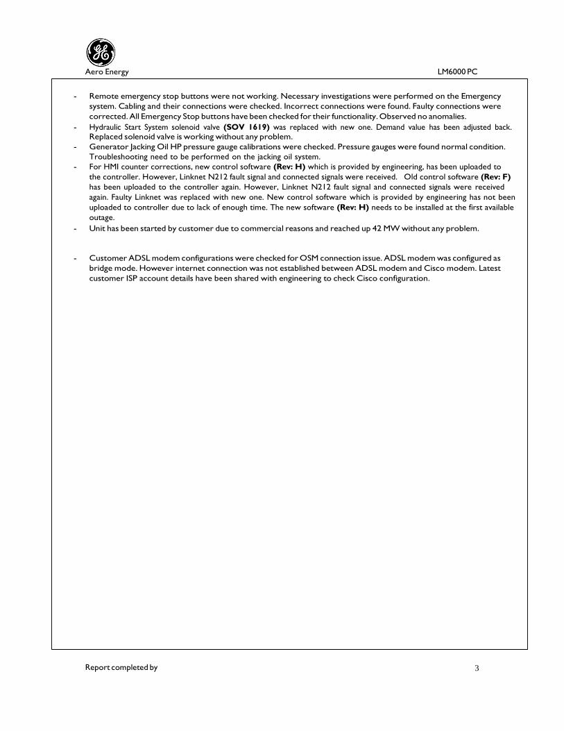
- Remote emergency stop buttons were not working. Necessary investigations were performed on the Emergency
system. Cabling and their connections were checked. Incorrect connections were found. Faulty connections were
corrected. All Emergency Stop buttons have been checked for their functionality. Observed no anomalies.
- Hydraulic Start System solenoid valve (SOV 1619) was replaced with new one. Demand value has been adjusted back. Replaced solenoid valve is working without any problem.
- Generator Jacking Oil HP pressure gauge calibrations were checked. Pressure gauges were found normal condition.
Troubleshooting need to be performed on the jacking oil system.
- For HMI counter corrections, new control software (Rev: H) which is provided by engineering, has been uploaded to
the controller. However, Linknet N212 fault signal and connected signals were received. Old control software (Rev: F)
has been uploaded to the controller again. However, Linknet N212 fault signal and connected signals were received
again. Faulty Linknet was replaced with new one. New control software which is provided by engineering has not been
uploaded to controller due to lack of enough time. The new software (Rev: H) needs to be installed at the first available
outage.
- Unit has been started by customer due to commercial reasons and reached up 42 MW without any problem.
- Customer ADSL modem configurations were checked for OSM connection issue. ADSL modem was configured as
bridge mode. However internet connection was not established between ADSL modem and Cisco modem. Latest
customer ISP account details have been shared with engineering to check Cisco configuration.

Aero Energy LM6000 PC
Report completed by 4
CONCLUSIONS & RECOMMENDATIONS
Open Items: - New control software which is provided by engineering has not been uploaded to
controller due to lack of enough time. The new software (Rev: H) needs to be installed at
the first available outage.
- (-) Polarity ground leakage was measured on the 24VDC system. It needs to be
investigated as soon as possible.
- Water Injection flow meter could not be replaced with new one due to lack of the spare
part on site. It needs to be replaced when the new flow meter delivered to the site.
- Customer ADSL modem configurations were checked for OSM connection issue. ADSL
modem was configured as bridge mode. However internet connection was not established
between ADSL modem and Cisco modem. Latest customer ISP account details have been
shared with engineering to check Cisco configuration.
- Generator Jacking Oil HP pressure gauge calibrations were checked. Pressure gauges
were found normal condition. Troubleshooting need to be performed on the jacking oil
system.
Follow Up Action Items Engineering:
Follow Up Action Items SM/CPM/PM:
Outage Data:
Engine Data:
ESN xxx-xxx Engine Fired Hours - Package Hours 43005
Model LM6000 PC Engine Fired Starts - Package Fired Starts 2513
Maintenance Data:
WP, SB, SL, PB, PL
Performed
Revision/manual reference Date
completed
Comments
WP 1711 00 T48 Thermocouple Inspection 31.05.2015 WP 4024 00 Vibration Monitoring System Check 01.06.2015 WP 4017 00 Chip Detector Check 01.06.2015
Parts Data:
Description PN Removed SN
Removed
Qty Disposition PN
Installed
SN
Installed
STROBE 382A5419P0001 - 1 Replaced 382A5419P0001 -
T48 1962M86P02 - 2 Replaced 1962M86P02 -
CHIP DETECTOR L43563P01 - 1 Replaced L43563P01 -
LINKNET 9905-970 - 1 Replaced 9905-970 -
GAS SENSOR 334A3940P0001 - 2 Replaced 334A3940P0001 -
IGNITER 9392M95P04 - 1 Replaced 9392M95P04 -
SOV1619 382A5502P0001 - 1 Replaced 382A5502P0001 -

Aero Energy LM6000 PC
Report completed by 5
UDETAILS AND DATA
Work performed
T48 Thermocouple Inspection
T48 Thermocouple Measurement
T48
Probe
Insulation Resistance
KP-KN
Insulation Resistance
KN-KP
Average
KP-KN(Ohm)
T48A 2.82 2.32 2.57
T48B 2.83 2.14 2.48
T48C 2.85 2.21 2.53
T48D 2.84 2.15 2.50
T48E 2.86 2.13 2.49
T48F 2.81 2.20 2.50
T48G 2.82 2.14 2.48
T48H 2.88 2.22 2.55
As per the GEK 105059 Volume II WP 1711 00; KP to KN circuit resistance should be between
2,4 ohm and 4,1 ohm. Insulation resistance between plug and case should be > 5Mohm.
Tag As Found As Left
-70 ºF 0 ºF 900 ºF 1600 ºF 1900 ºF -70 ºF 0 ºF 900 ºF 1600ºF 1900 ºF
T48 A -70.41 -1.31 902.18 1603.44 1903.21 -69.98 0.04 900.35 1600.65 1899.89
T48 B -71.81 -2.23 901.20 1602.54 1902.52 -69.98 0.04 900.31 1600.43 1899.96
T48 C -72.62 -2.44 901.73 1602.78 1902.05 -69.97 0.03 900.42 1600.33 1900.06
T48 D -73.18 -2.83 900.94 1601.27 1900.76 -70.02 0.08 900.54 1600.52 1900.03
T48 E -72.38 -2.18 900.76 1602.03 1901.51 -69.99 0.02 900.41 1600.45 1900.07
T48 F -69.96 0.06 902.84 1603.67 1903.17 -69.96 0.06 900.23 1600.34 1900.13
T48 G -69.98 0.03 901.45 1604.26 1903.82 -69.97 0.03 900.21 1600.42 1899.96
T48 H -71.21 -1.44 902.31 1603.18 1902.54 -69.96 0.07 900.43 1600.28 1900.04
- Turbine Control system simulated and re- tuned according to T48 low and high set points. Observed no big
differences.
- Between KP/KN and case ohm was > 5Mohm for all the probes.

Aero Energy LM6000 PC
Report completed by 6
UDETAILS AND DATA
T3 Calibration Data
T3A
TE-6838A
T3B
TE-6838B
Range -70 to 1200 ºF Range -70 to 1200 ºF
KP-KN KN-KP KP-KN KN-KP
Resistance 5.8 5.2 Resistance 5.8 5.2
Sim.
Temperature
As Found
As Left
Sim.
Temperature
As Found
As Left
-70 -70.54 -69.97 -70 -70.68 -69.99
0 -0.84 0.04 0 -0.57 0.11
400 399.24 399.89 400 399.61 399.85
800 801.84 800.04 800 801.78 799.98
1200 1202.63 1199.97 1200 1203.44 1199.96
As per the GEK 105059, Volume I, between A and B and between C and D pins
Resistance should be between 4,3 ohm and 6 Ohms.
- Turbine Control system simulated and re- tuned according to T3 low and high set points. Observed small differences
(max. 4-5 Fahrenheit) before the simulation.
- On- engine and off-engine cable sockets were cleaned with Contact Cleaner before the re-installation.
T2 Calibration Data
T2A T2B
Range -70 to 500 ºF Range -70 to 500 ºF
Sim.
Temp.
As Found
As Left
Sim.
Temp.
As Found
As Left
-70 -69.94 -69.94 -70 -70.01 -70.01
0 0.21 0.21 0 0.32 0.32
120 120.07 120.07 120 120.12 120.12
250 250.12 250.12 250 250.41 250.41
500 500.15 500.15 500 500.18 500.18

Report completed by 7
Aero Energy LM6000 PC
DETAILS AND DATA
Work performed:
T25 Calibration Data
T25A T25B
Range -70 to 500 ºF Range -70 to 500 ºF
Sim.
Temp.
As Found
As Left
Sim.
Temp.
As Found
As Left
-70 -70.02 -70.02 -70 -69.96 -69.96
0 0.02 0.02 0 0.04 0.04
150 150.11 150.11 150 150.07 150.07
300 300.09 300.09 300 300.14 300.14
500 500.18 500.18 500 500.21 500.21
Calibration Data of Pressure Transmitters
Ambient pressure was measured as 14.45 PSI.
Tag P0
Range 0-16 PSIA
Actual
PSIG
As Found
PSIA
As Left
PSIA
-12.00 2.43 2.43
0 14.44 14.44
1.6 16.04 16.04
P25 Calibration Data
Tag P25A Tag P25B
Range 0 - 100 PSIA Range 0 - 100 PSIA
Actual
PSIG
As Found
PSIA
As Left
PSIA
Actual
PSIG
As Found
PSIA
As Left
PSIA
-12.00 2.46 2.46 -12.00 2.45 2.46
0 14.45 14.45 0 14.48 14.48
50.0 64.46 64.46 50.0 64.46 64.46
75.0 89.45 89.45 75.0 89.47 89.47
85.6 100.04 100.04 85.6 100.11 100.11

Report completed by 8
Aero Energy LM6000 PC
DETAILS AND DATA
Work performed:
PS3 Calibration Data
Tag PS3 A Tag PS3 B
Range 0-600 PSIA Range 0-600 PSIA
Actual
%
Actual
PSIG
As Found
PSIA
As Left
PSIA
Actual
%
Actual
PSIG
As Found
PSIA
As Left
PSIA
Vacuum -12.00 2.46 2.46 Vacuum -12.00 2.45 2.45
%0 0 14.46 14.46 %0 0 14.46 14.46
%50 300 314.46 314.46 %50 300 314.46 314.46
%75 400 414.48 414.48 %75 400 414.47 414.47
%100 585.6 600.04 600.04 %100 585.6 600.02 600.02
PTB Calibration Data
Tag PTB A Tag PTB B
Range 0-300 PSIA Range 0-300 PSIA
Actual
PSIG
As Found
PSIA
As Left
PSIA
Actual
PSIG
As Found
PSIA
As Left
PSIA
-12.0 3.44 2.44 -12.0 2.46 2.46
0 15.68 14.46 0 14.45 14.45
150.00 166.52 164.51 150.00 164.44 164.44
285.6 302.31 300.03 285.6 300.02 300.02
P48 Calibration Data
Tag P48
Range 0-150 PSIA
Actual PSIG As Found PSIA As Left PSIA
-12.00 2.43 2.43
0 14.45 14.45
75.00 89.47 89.47
135.6 150.04 150.04

Report completed by 9
Aero Energy LM6000 PC
Redundant Over-speed System Check U
Speed signals are simulated from the off-engine cable via signal generator. Speed signals have been monitored
as shown below tables. The alarm and trip points have been appeared on the Alarm Page when we send;
Redundant over speed system check was carried out according to the following set points.
1 Rpm = 0.7491 Hz
Alarm Point: > 10700 Rpm = 8015 Hz
Trip Point: > 10800 Rpm = 8090.3 Hz
For NSD Speed Sensors;
1Rpm = 0.8 Hz
Trip Point > 4050 Rpm = 3240 Hz
XN25A XN25B
Actual
(Hz)
Actual
(rpm)
HMI
(rpm)
Actual
(Hz)
Actual
(rpm)
HMI
(rpm) 2000 2669.89 2670 2000 2669.89 2670 4000 5339.73 5340 4000 5339.74 5340 6000 8009.61 8010 6000 8009.61 8009 8016
(alarm) 10700.84 10701 8016
(alarm)
10700.81 10701
8090
(trip) 10799.72 10800 8090
(trip)
10799.71 10800
NSDA NSDB
Actual
(Hz)
Actual
(rpm)
HMI
(RPM)
Actual
(Hz)
Actual
(rpm)
HMI
(RPM) 1000 1250.01 1250 1000 1250.01 1250 2000 2500.03 2500 2000 2500.02 2500 3000 3749.99 3750 3000 3749.99 3750 3240
(trip) 4050.02 4050 3240
(trip) 4050.02 4050
Aero Energy LM6000 PC
Report completed by 10
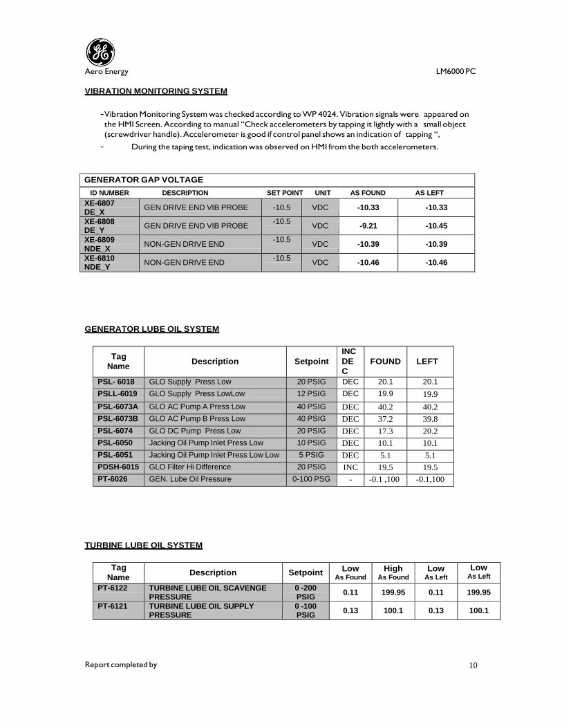
VIBRATION MONITORING SYSTEM
- Vibration Monitoring System was checked according to WP 4024. Vibration signals were appeared on
the HMI Screen. According to manual “Check accelerometers by tapping it lightly with a small object
(screwdriver handle). Accelerometer is good if control panel shows an indication of tapping “,
- During the taping test, indication was observed on HMI from the both accelerometers.
GENERATOR GAP VOLTAGE
ID NUMBER DESCRIPTION SET POINT UNIT AS FOUND AS LEFT
XE-6807 DE_X
GEN DRIVE END VIB PROBE -10.5 VDC -10.33 -10.33
XE-6808 DE_Y
GEN DRIVE END VIB PROBE -10.5
VDC -9.21 -10.45
XE-6809 NDE_X
NON-GEN DRIVE END -10.5
VDC -10.39 -10.39
XE-6810 NDE_Y
NON-GEN DRIVE END -10.5
VDC -10.46 -10.46
GENERATOR LUBE OIL SYSTEM
Tag
Name
Description
Setpoint
INC
DE
C
FOUND
LEFT
PSL- 6018 GLO Supply Press Low 20 PSIG DEC 20.1 20.1
PSLL-6019 GLO Supply Press LowLow 12 PSIG DEC 19.9 19.9
PSL-6073A GLO AC Pump A Press Low 40 PSIG DEC 40.2 40.2
PSL-6073B GLO AC Pump B Press Low 40 PSIG DEC 37.2 39.8
PSL-6074 GLO DC Pump Press Low 20 PSIG DEC 17.3 20.2
PSL-6050 Jacking Oil Pump Inlet Press Low 10 PSIG DEC 10.1 10.1
PSL-6051 Jacking Oil Pump Inlet Press Low Low 5 PSIG DEC 5.1 5.1
PDSH-6015 GLO Filter Hi Difference 20 PSIG INC 19.5 19.5
PT-6026 GEN. Lube Oil Pressure 0-100 PSG - -0.1 ,100 -0.1,100
TURBINE LUBE OIL SYSTEM
Tag
Name Description Setpoint
Low As Found
High As Found
Low As Left
Low As Left
PT-6122 TURBINE LUBE OIL SCAVENGE PRESSURE
0 -200 PSIG
0.11 199.95 0.11 199.95
PT-6121 TURBINE LUBE OIL SUPPLY PRESSURE
0 -100 PSIG
0.13 100.1 0.13 100.1

Aero Energy LM6000 PC
Report completed by 11
Tag Name Description SP Unit INC
DEC
NO/
NC Found Left
PDSH-6120 TURB L/O SUPPLY FILTER HI DP 20 PSID INC NC 20.1 20.1
PDSHH-6144 TURB L/O SUPPLY FILTER HI HI DP 25 PSID INC NC 25.4 25.4
PDSH-6118 TURB SCAVENGE FILTER HI DP 20 PSID INC NC 19.95 19.95
PDSHH-6119 TURB SCAVENGE FILTER HI HI DP 25 PSID INC NC 25.2 25.2
PSLL-6115 TURBINE LUBE LO LO PRESS 15 PSIG DEC NO 13.5 15.0
PSLL-6116 TURBINE LUBE LO LO PRESS 6 PSIG DEC NO 6.1 6.1
PSH-6117 TURB SCAV OIL PUMP PRESS HI 100 PSIG INC NC 99.5 99.5
PSLL-1605 HYD STARTER SKID PRESSURE LO LO 250 PSIG DEC NO 249 249
PDSH-6146 TURBINE VG LUBE OIL FILTER DP 20 PSIG INC NC 21.1 21.1
Pressure switches were calibrated within +- 1 PSIG of set-point.
FIRE PROTECTION SYSTEM

Aero Energy LM6000 PC
Report completed by 12
Tag Name
Description
Setpoint
Unit
Found
( ma )
Left
%0 LEL
( ma )
Left
%50
LEL
( ma )
AE-6304A TURBINE GAS
DETECTOR 50% LEL 4.0 4.0 12.0
AE-6304B TURBINE GAS
DETECTOR 50% LEL 5.1 4.0 12.0
AE-6304C TURBINE GAS
DETECTOR 50% LEL 3.8 4.0 12.0
AE-6304D TURBINE GAS
DETECTOR 50% LEL 4.2 4.0 12.0
AE-6304E TURBINE GAS
DETECTOR 50% LEL 3.5 4.0 12.0
AE-6313 GENERATOR GAS
DETECTOR 50% LEL 4.0 4.0 12.0
CHIP DETECTORS
Tag Name Resistance As Found Test Results As Left
MCD 6865 Open Circ. 161 Ohms 2 Ohms 161 Ohms
MCD 6866 Open Circ. 161 Ohms 3 Ohms 161 Ohms
MCD 6870 Open Circ. 161 Ohms 2 Ohms 161 Ohms
BATTERY SYSTEMS
24 VDC CONTROL SYSTEM BATTERY VOLTAGES
POSITIVE TO NEGATIVE +27.35 VDC
POSITIVE TO GROUND +27.05 VDC
NEGATIVE TO GROUND -0.30 VDC
BATTERY WATER LEVELS NORMAL
24 VDC FIRE SYSTEM BATTERY VOLTAGES
POSITIVE TO NEGATIVE +27.15 VDC
POSITIVE TO GROUND +13.55 VDC
NEGATIVE TO GROUND -13.60 VDC
BATTERY WATER LEVELS NORMAL
125 VDC SYSTEM BATTERY VOLTAGES
POSITIVE TO NEGATIVE +133.20 VDC
POSITIVE TO GROUND +66.35 VDC
NEGATIVE TO GROUND -65.70 VDC
BATTERY WATER LEVELS -

Aero Energy LM6000 PC
Report completed by 13
Ambient Pressure Replaced Combustible Gas Sensor
Replaced T48 Thermocouples Replaced Chip Detector
Replaced Igniter Replaced RTD 6 Channel Linknet

Aero Energy LM6000 PC
Report completed by 14
Replaced Hydraulic System SOV1619 Replaced Fire Protection System Strobe
Fire Protection System Function Checks DC Battery System

Report completed by 15
Aero Energy LM6000 PC
HMI SCREENS
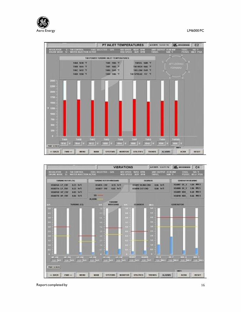
Report completed by 16
Aero Energy LM6000 PC

Report completed by 17
Aero Energy LM6000 PC

Report completed by 18
Aero Energy LM6000 PC

Report completed by 19
Aero Energy LM6000 PC

Report completed by 20
Aero Energy LM6000 PC

Aero Energy LM6000 PC
20

Aero Energy LM6000 PC
21