unit-2 solar energy storage, applications & wind energy
TRANSCRIPT

Green Engineering Systems (Unit-2)
Singuru Rajesh, Asst. Prof, Dept. of Mechanical Engg., Raghu Engineering. College, Visakhapatnam
1
UNIT-2 SOLAR ENERGY STORAGE, APPLICATIONS & WIND ENERGY
Syllabus
Solar Energy Storage and Applications: Different Methods, sensible and latent heat and stratified
storage, solar ponds, solar applications- solar heating/cooling technique, solar distillation and
drying, solar cookers, central power tower concept and solar chimney
Wind Energy: Sources and potentials, horizontal and vertical axis, wind mills, performance
characteristics, betz criteria, types of winds, wind data measurement
----------x---------
SOLAR ENERGY STORAGE AND APPLICATIONS
Thermal Energy Storage:
The Thermal storage system (TES) stores energy when the collected amount is excess of the
requirement of the application and discharges energy when the collected amount is in adequate. These
systems correct the mismatch between the supply and demand of energy.
Three types of storage on the basis of Time
1. Buffer Storage (Short interval of time 4- 6 hours)
2. Diurnal Storage (Short interval of time 24 hours)
3. Annual Storage (long interval for a year)
Methods of TES:
Fig. Methods of TES
Sensible Heat Storage: Heating a liquid or a solid which does not changes phase. This is called
Sensible Heat Storage. Energy stored in vibrational modes of molecules i.e., change in phase
(sand, concrete, molten salts, etc.).
Latent Heat Storage: Heating a material which undergoes a phase change. This is called Latent
Heat Storage. Energy stored in media as it changes phase (ice/water, etc.). The amount of energy
stored in this case depends upon the mass and the latent heat of fusion of the material.

Green Engineering Systems (Unit-2)
Singuru Rajesh, Asst. Prof, Dept. of Mechanical Engg., Raghu Engineering. College, Visakhapatnam
2
Thermochemical Energy: Energy stored in chemical bonds of molecules (metal oxides,
reversible oxidation, etc.). Using heat to induce a certain chemical reaction and then storing the
products.
Considerations followed in design and use of TES
Relevant Temperature range over which the storage has to operate
Heat losses from storage has to be minimum
Low cost, non-toxic storage media
Capacity of the storage has a significant effect on the operation of the rest of the system especially
the collectors
1. Sensible Heat Storage for TES
Energy is stored or extracted by heating or cooling a liquid or a solid which does not change
its phase during the process. Substances used in this for liquids like water, heat transfer oils and
certain inorganic molten salts and Solids like rocks, pebbles and refractories. The choice of substance
is largely depends on the temperature level. This is simpler in design than the remaining two. First
disadvantage is being bigger in size of the storage. Second disadvantage is the constant temperature
in the storage system cannot be maintained.
Table 1: Liquid and Solid of Latent Heat Storage Systems
Liquid Solid
Water storage tanks are made from a variety
of materials like Steel, concrete and
fibreglass.
Water 100OC
Servotherm (Light and Medium) 150OC
Hitech 425OC
Liquid Sodium etc.. 760OC
Energy can be stored in rocks, pebbles
packed in insulated vessels.
Rocks
Pebbles
Magnesium oxides
Aluminium Oxides
Silicon Oxides
(i) Well Mixed Situation
Green Engineering Systems (Unit-2)
Singuru Rajesh, Asst. Prof, Dept. of Mechanical Engg., Raghu Engineering. College, Visakhapatnam
3
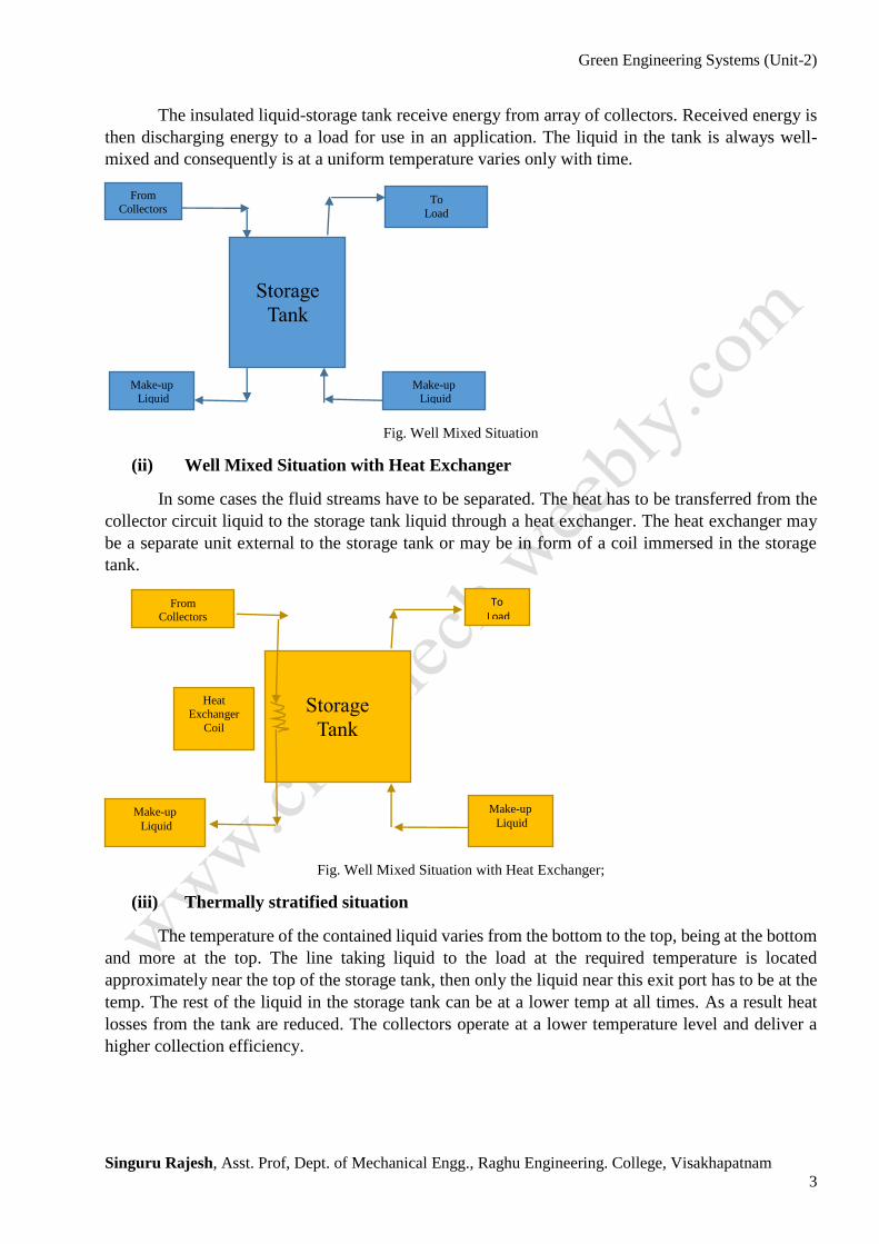
The insulated liquid-storage tank receive energy from array of collectors. Received energy is
then discharging energy to a load for use in an application. The liquid in the tank is always well-
mixed and consequently is at a uniform temperature varies only with time.
Fig. Well Mixed Situation
(ii) Well Mixed Situation with Heat Exchanger
In some cases the fluid streams have to be separated. The heat has to be transferred from the
collector circuit liquid to the storage tank liquid through a heat exchanger. The heat exchanger may
be a separate unit external to the storage tank or may be in form of a coil immersed in the storage
tank.
Fig. Well Mixed Situation with Heat Exchanger;
(iii) Thermally stratified situation
The temperature of the contained liquid varies from the bottom to the top, being at the bottom
and more at the top. The line taking liquid to the load at the required temperature is located
approximately near the top of the storage tank, then only the liquid near this exit port has to be at the
temp. The rest of the liquid in the storage tank can be at a lower temp at all times. As a result heat
losses from the tank are reduced. The collectors operate at a lower temperature level and deliver a
higher collection efficiency.
Storage
Tank
From
Collectors To
Load
Make-up
Liquid
Make-up
Liquid
From Collectors
To
Load
Make-up
Liquid Make-up
Liquid
Storage
Tank
Heat
Exchanger
Coil

Green Engineering Systems (Unit-2)
Singuru Rajesh, Asst. Prof, Dept. of Mechanical Engg., Raghu Engineering. College, Visakhapatnam
4
Fig. Thermal Stratification Tank Fig. Packed Bed
(iv) Packed Bed Storage:
The unit is packed with rocks, pebbles or bricks through which air is circulated shown in
above figure. Hot air from solar air heaters is usually passed down through the bed when sensible
heat is to be stored in the particulate solid. While cold air from the load is circulated upwards when
heat is to be extracted from the solid. Unlike a liquid storage tank, the two processes cannot be
executed simultaneously.
2. Latent Heat Storage for TES
Energy is stored or extracted by heating or cooling a liquid or a solid which change in its
phase during the process. Heat is stored in a material when it melts and extracted from the material
when it freezes. This type of materials are called as Phase Change Materials or PCM
Properties required for Latent Heat Storage are
A melting point in the temperature range of the application for which it is being considered
A value of the latent heat of fusion
A small volume change during the phase change
Table: Organic Materials and Inorganic Materials of Latent Heat Storage System
Organic Materials Inorganic Materials
Parrafin Wax PII6E
(Melting Point 42-50oC)
Capric Acid
(Melting Point 32oC)
Hydrate Salts.
Calcium Chloride Hexahydrate,
Ice H20
Sodium nitrate, NaNo3
Sodium Hydroxide NaOH
Lithium Carbonate LiCO3
potassium carbonate
An advantage associated with a latent heat storage system is that it is more compact than a
sensible heat system. The Heat exchange system for transferring energy between the working fluid
Storage Tank
(T1)
Storage Tank
(T2)
From Collectors
To
Load
Make-up
Liquid
Make-up
Liquid
Pebbles
Inlet Air
Outlet
hot air
Green Engineering Systems (Unit-2)
Singuru Rajesh, Asst. Prof, Dept. of Mechanical Engg., Raghu Engineering. College, Visakhapatnam
5
(which is usually a gas) and the storage material is always more complex. A large improvement in
the heat transfer rate is obtained by encapsulating the PCM in small plastic spheres to form a packed
bed storage unit. High pressure drop of the heat transfer fluid through the bed and high initial cost of
encapsulation are the major draw backs. In order to increase the thermal conductivity of the PCM,
Metal Matrix structures, Aluminum shavings etc… have been tried.
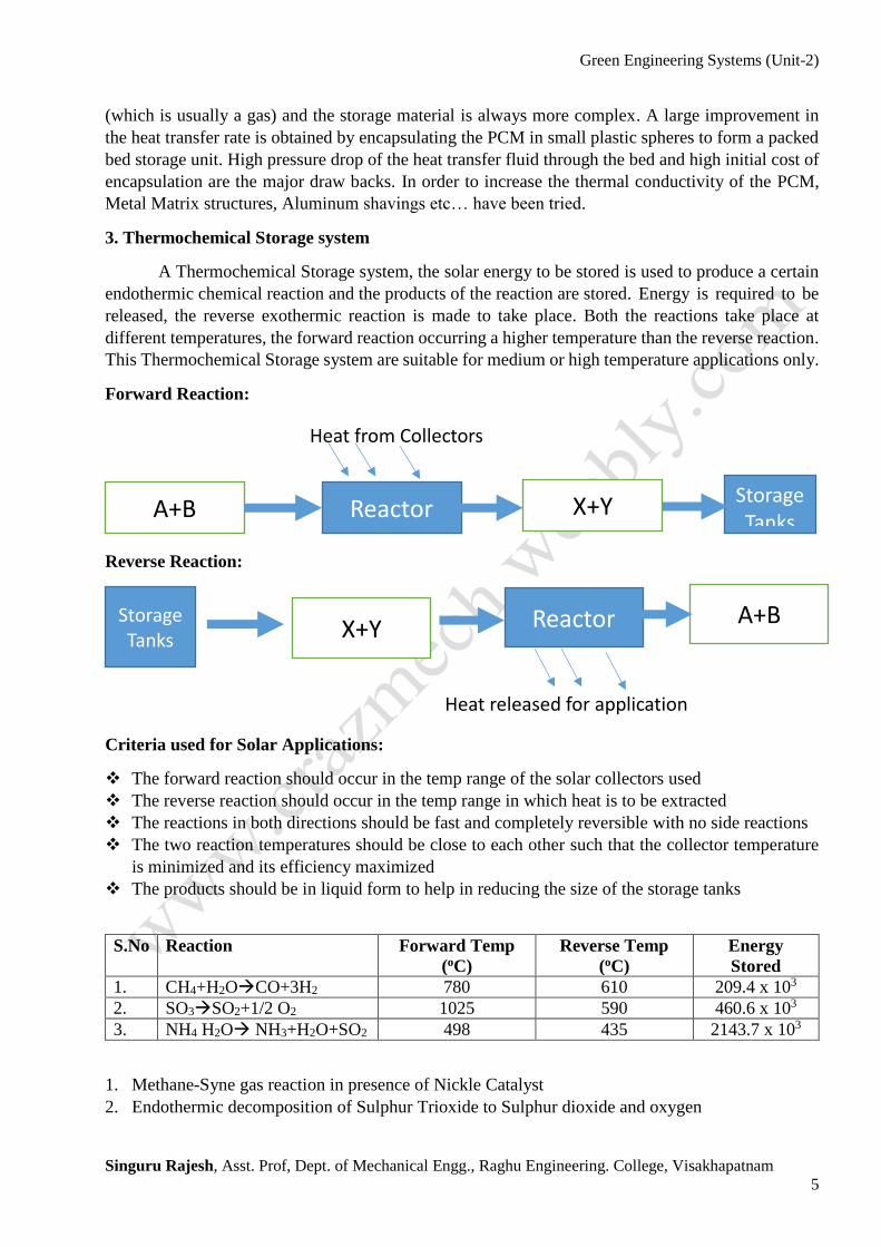
3. Thermochemical Storage system
A Thermochemical Storage system, the solar energy to be stored is used to produce a certain
endothermic chemical reaction and the products of the reaction are stored. Energy is required to be
released, the reverse exothermic reaction is made to take place. Both the reactions take place at
different temperatures, the forward reaction occurring a higher temperature than the reverse reaction.
This Thermochemical Storage system are suitable for medium or high temperature applications only.
Forward Reaction:
Reverse Reaction:
Criteria used for Solar Applications:
The forward reaction should occur in the temp range of the solar collectors used
The reverse reaction should occur in the temp range in which heat is to be extracted
The reactions in both directions should be fast and completely reversible with no side reactions
The two reaction temperatures should be close to each other such that the collector temperature
is minimized and its efficiency maximized
The products should be in liquid form to help in reducing the size of the storage tanks
S.No Reaction Forward Temp
(oC)
Reverse Temp
(oC)
Energy
Stored
1. CH4+H2OCO+3H2 780 610 209.4 x 10³
2. SO3SO2+1/2 O2 1025 590 460.6 x 10³
3. NH4 H2O NH3+H2O+SO2 498 435 2143.7 x 103
1. Methane-Syne gas reaction in presence of Nickle Catalyst
2. Endothermic decomposition of Sulphur Trioxide to Sulphur dioxide and oxygen
Reactor Storage Tanks
X+Y A+B
Heat from Collectors
Reactor Storage Tanks X+Y
A+B
Heat released for application

Green Engineering Systems (Unit-2)
Singuru Rajesh, Asst. Prof, Dept. of Mechanical Engg., Raghu Engineering. College, Visakhapatnam
6
3. Decomposition of Hydrogen Sulphate into Ammonia, water and sulphur trioxide in the forward
reaction
Solar Pond:
About 2 to 3 meters deep with a thick durable plastic liner laid at the bottom. Materials include
Low density Polyethylene and High Density polyethylene. Salts like Magnesium chloride, sodium
chloride or sodium nitride are dissolved in the water
Zones in Solar Pond
Surface Convective Zone (10-20cm)
Non-Convective Zone (half of the depth of pond)
Low-Convective Zone (temp is const.)
Solar Pond
Working:
When the sun's rays contact the bottom of a shallow pool, they heat the water adjacent to the
bottom. When water at the bottom of the pool is heated, it becomes less dense than the cooler water
above it, and convection begins. Solar ponds heat water by impeding this convection. Salt is added to
the water until the lower layers of water become completely saturated.
High-salinity water at the bottom of the pond does not mix readily with the low-salinity water
above it, so when the bottom layer of water is heated, convection occurs separately in the bottom and
top layers, with only mild mixing between the two. This greatly reduces heat loss, and allows for the
high-salinity water to get up to 90 °C while maintaining 30 °C low-salinity water. This hot, salty
water can then be pumped away for use in electricity generation, through a turbine or as a source of
thermal energy.
Advantages and Dis-advantages:
The approach is particularly attractive for rural areas in developing countries. Very large area
collectors can be set up for just the cost of the clay or plastic pond liner.
The accumulating salt crystals have to be removed and can be a valuable by-product and a
maintenance expense.
No need for a separate collector.
The extremely-large thermal mass means power is generated night and day.
Relatively low-temperature operation means solar energy conversion is typically less than 2%.
Due to evaporation, non-saline water is constantly required to maintain salinity gradients.

Green Engineering Systems (Unit-2)
Singuru Rajesh, Asst. Prof, Dept. of Mechanical Engg., Raghu Engineering. College, Visakhapatnam
7
Solar Cooker

Green Engineering Systems (Unit-2)
Singuru Rajesh, Asst. Prof, Dept. of Mechanical Engg., Raghu Engineering. College, Visakhapatnam
8
Solar Distillation
Solar Distillation
A solar still evaporates the water with substances dissolved in it causing the heat of the Sun
to evaporate water so that it may be cooled and collected, thereby purifying it. They are used in areas
where drinking water is unavailable, so that clean water is obtained from dirty water or from plants
by exposing them to sunlight.
There are many types of solar still, including large scale concentrated solar
stills and condensation traps (better known as moisture traps amongst survivalists). In a solar still,
impure water is contained outside the collector, where it is evaporated by sunlight shining through
clear plastic or glass. The pure water vapor condenses on the cool inside surface and drips down,
where it is collected and removed.
Distillation replicates the way nature makes rain. The sun's energy heats water to the point of
evaporation. As the water evaporates, water vapor rises, condensing into water again as it cools and
can then be collected. This process leaves behind impurities, such as salts and heavy metals, and
eliminates microbiological organisms. The end result is pure distilled water.
Solar Dryer

Green Engineering Systems (Unit-2)
Singuru Rajesh, Asst. Prof, Dept. of Mechanical Engg., Raghu Engineering. College, Visakhapatnam
9
WIND ENERGY
The wind turbine captures the wind’s kinetic energy in a rotor consisting of two or more blades
mechanically coupled to an electrical generator. The turbine is mounted on a tall tower to enhance
the energy capture. Numerous wind turbines are installed at one site to build a wind farm of the
desired power generation capacity. Obviously, sites with steady high wind produce more energy over
the year.
The wind is a by-product of solar energy. Approximately 2% of the sun's energy reaching the
earth is converted into wind energy. The surface of the earth heats and cools unevenly, creating
atmospheric pressure zones that make air flow from high-to low-pressure areas. The wind has played
an important role in the history of human civilization. First true windmill, a machine with vanes
attached to an axis to produce circular motion, may have been built as early as 2000 B.C
These too were used for milling grain. It was not until a few hundred years later that windmills
were modified to pump water. Until the diesel engine came along, many transcontinental rail routes
in the U.S. depended on large multi-vane windmills to pump water for steam locomotives. They are
best suited for pumping ground water in small quantities to livestock water tanks. These wind turbines
provided electricity to farms.
Fig. Wind Turbine Machines in Off Shore and On Shore
A typical modern windmill looks as shown in the following figure. Because it is invisible, it
is not easily measured without special instruments. Wind velocity is affected by the trees, buildings,
hills and valleys around us. Wind is a diffuse energy source that cannot be contained or stored for use
elsewhere or at another time.
Green Engineering Systems (Unit-2)
Singuru Rajesh, Asst. Prof, Dept. of Mechanical Engg., Raghu Engineering. College, Visakhapatnam
10
In India Tamil Nadu, Maharashtra, Karnataka, Rajasthan, Gujarat and Andhra Pradesh.
Kandala and Indore are both places for locating wind machines from the point of view of the energy
content in the wind. In India, many such areas have been identified along the west and east coasts, as
on the Deccan plateau, and it is estimated that there is a potential for installing at least 15,000 MW
of power from wind energy.
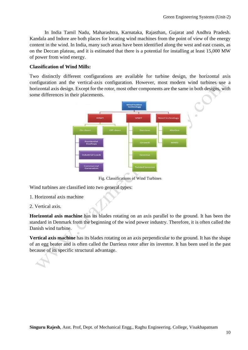
Classification of Wind Mills:
Two distinctly different configurations are available for turbine design, the horizontal axis
configuration and the vertical-axis configuration. However, most modern wind turbines use a
horizontal axis design. Except for the rotor, most other components are the same in both designs, with
some differences in their placements.
Fig. Classifications of Wind Turbines
Wind turbines are classified into two general types:
1. Horizontal axis machine
2. Vertical axis.
Horizontal axis machine has its blades rotating on an axis parallel to the ground. It has been the
standard in Denmark from the beginning of the wind power industry. Therefore, it is often called the
Danish wind turbine.
Vertical axis machine has its blades rotating on an axis perpendicular to the ground. It has the shape
of an egg beater and is often called the Darrieus rotor after its inventor. It has been used in the past
because of its specific structural advantage.

Green Engineering Systems (Unit-2)
Singuru Rajesh, Asst. Prof, Dept. of Mechanical Engg., Raghu Engineering. College, Visakhapatnam
11
Horizontal axis machine has its blades rotating on an axis parallel to the ground. This is the most
common wind turbine design. In addition to being parallel to the ground, the axis of blade rotation is
parallel to the wind flow. Some machines are designed to operate in an upwind mode, with the blades
upwind of the tower. In this case, a tail vane is usually used to keep the blades facing into the wind.
Some very large wind turbines use a motor-driven mechanism that turns the machine in response to
a wind direction sensor mounted on the tower. Commonly found horizontal axis wind mills are
1. Aero-turbine mill with 35% efficiency
2. Farm mills with 15% efficiency
Vertical axis machine has its blades rotating on an axis perpendicular to the ground. Although
vertical axis wind turbines have existed for centuries, they are not as common as their horizontal
counterparts. The main reason for this is that they do not take advantage of the higher wind speeds at
higher elevations above the ground as well as horizontal axis turbines. The basic vertical axis designs
are the
• Savonius, which uses scoops to catch the wind & the efficiency of 30%.
• Darrieus, which has curved blades & efficiency of 35%,
• Giromill or H-Darrieeus which has straight blades & efficiency of 35%
Type of Vertical Axis Wind Turbine Machines

Green Engineering Systems (Unit-2)
Singuru Rajesh, Asst. Prof, Dept. of Mechanical Engg., Raghu Engineering. College, Visakhapatnam
12
Fig. Vertical Axis Wind Turbine Machine models in our college
A vertical axis machine need not be oriented with respect to wind direction. Because the shaft
is vertical, the transmission and generator can be mounted at ground level allowing easier servicing
and a lighter weight, lower cost tower. Although vertical axis wind turbines have these advantages,
their designs are not as efficient at collecting energy from the wind as are the horizontal machine
designs.
Fig. Horizontal Axis Wind Turbine Machine components
Components 1. Rotor
2. Blades
3. Hub
4. Main Rotating Shaft
5. Gear Box System
6. Generator
7. Housing
Specification of Large Wind Machine in INDIA Rated Capacity 2.1 MW
Rotor Diameter 88m
Hub Height 80m
Cut-in wind Speed 3-4m/s
Cut-out Speed 25m/s
Number of blades 3
Power control Active blade pitching
Generator Type Asynchronous
Location Pune, Maharashtra, India

Green Engineering Systems (Unit-2)
Singuru Rajesh, Asst. Prof, Dept. of Mechanical Engg., Raghu Engineering. College, Visakhapatnam
13
8. Anemometer
9. Pitching System
10. Yaw system
11. Tower
12. Grid Connection
13. Cables and
14. Foundation
Types of Winds
1. Planetary winds or Permanent Winds
2. Periodic Winds
3. Local Winds
1. Planetary winds or Permanent Winds
These winds blow from high pressure belts to low pressure belts in the same direction throughout the
year. They blow over vast area of continents and Oceans.
1. Easterlies
2. Westerlies
3. Polar Easterlies
The winds blowing throughout the year from one latitude to another in response to latitudinal
differences in air pressure are called “planetary or prevailing winds”. They involve large areas of the
globe.
2. Periodic Winds
The direction of these winds changes with the change of seasons. Monsoon winds are the
important periodic winds. Periodic winds change their direction periodically with the change in
season, e.g., Monsoons, Land and Sea Breezes, Mountain and Valley Breezes
Monsoon Wind are seasonal winds and refer to wind systems that have a pronounced, seasonal
reversal of direction. According to ‘Flohn’, monsoon is a seasonal modification of general
Planetary Wind System. Summer monsoon is called South Westerly Wind and is characterized
by highly variable weather with frequent spells of drought and heavy rains. The winter monsoon
is a gentle drift of air in which winds blow from the north-east and is known as North Easterly
Wind.
Green Engineering Systems (Unit-2)
Singuru Rajesh, Asst. Prof, Dept. of Mechanical Engg., Raghu Engineering. College, Visakhapatnam
14
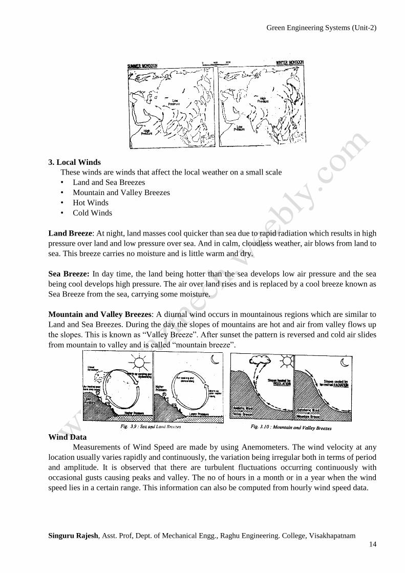
3. Local Winds
These winds are winds that affect the local weather on a small scale
• Land and Sea Breezes
• Mountain and Valley Breezes
• Hot Winds
• Cold Winds
Land Breeze: At night, land masses cool quicker than sea due to rapid radiation which results in high
pressure over land and low pressure over sea. And in calm, cloudless weather, air blows from land to
sea. This breeze carries no moisture and is little warm and dry.
Sea Breeze: In day time, the land being hotter than the sea develops low air pressure and the sea
being cool develops high pressure. The air over land rises and is replaced by a cool breeze known as
Sea Breeze from the sea, carrying some moisture.
Mountain and Valley Breezes: A diurnal wind occurs in mountainous regions which are similar to
Land and Sea Breezes. During the day the slopes of mountains are hot and air from valley flows up
the slopes. This is known as “Valley Breeze”. After sunset the pattern is reversed and cold air slides
from mountain to valley and is called “mountain breeze”.
Wind Data
Measurements of Wind Speed are made by using Anemometers. The wind velocity at any
location usually varies rapidly and continuously, the variation being irregular both in terms of period
and amplitude. It is observed that there are turbulent fluctuations occurring continuously with
occasional gusts causing peaks and valley. The no of hours in a month or in a year when the wind
speed lies in a certain range. This information can also be computed from hourly wind speed data.

Green Engineering Systems (Unit-2)
Singuru Rajesh, Asst. Prof, Dept. of Mechanical Engg., Raghu Engineering. College, Visakhapatnam
15
Betz's law
Betz's law indicates the maximum power that can be extracted from the wind, independent of
the design of a wind turbine in open flow. According to Betz's law, no turbine can capture more than
16/27 (59.3%) of the kinetic energy in wind. The factor is known as Betz's coefficient. Practical
utility-scale wind turbines achieve at peak 75% to 80% of the Betz limit. It is the flow of air over the
blades and through the rotor area that makes a wind turbine function. The wind turbine extracts energy
by slowing the wind down.
The theoretical maximum amount of energy in the wind that can be collected by a wind
turbine's rotor is approximately 59.3%.This value is known as the Betz limit. If the blades were 100%
efficient, a wind turbine would not work because the air, having given up all its energy, would entirely
stop. If all of the energy coming from wind movement through a turbine were extracted as useful
energy, the wind speed afterwards would drop to zero. If the wind stopped moving at the exit of the
turbine, then no more fresh wind could get in; it would be blocked.
In order to keep the wind moving through the turbine, there has to be some wind movement,
however small, on the other side with some wind speed greater than zero. Betz's law shows that as
air flows through a certain area, and as wind speed slows from losing energy to extraction from a
turbine, the airflow must distribute to a wider area. As a result, geometry limits any turbine efficiency
to a maximum of 59.3%.
------------X-----------