unit 2 the input/output system -...
TRANSCRIPT
The Input / Output
System UNIT 2 THE INPUT/OUTPUT SYSTEM Structure Page No.
2.0 Introduction 43 2.1 Objectives 43 2.2 Input / Output Devices or External or Peripheral Devices 43 2.3 The Input Output Interface 44 2.4 The Device Controllers and its Structure 46 2.4.1 Device Controller 2.4.2 Structure of an Input /Output Interface 2.5 Device Drivers 48 2.6 Input Output Techniques 50 2.6.1 Programmed Input /Output
2.6.2 Interrupt-Driven Input /Output 2.6.3 Interrupt-Processing 2.6.4 DMA (Direct Memory Access)
2.7 Input Output Processors 59 2.8 External Communication Interfaces 61 2.9 Summary 62 2.10 Solutions /Answers 62
2.0 INTRODUCTION
In the previous Unit, we have discussed the memory system for a computer system that contains primary memory, secondary memory, high speed memory and their technologies; the memory system of micro-computers i.e., their chips and types of memory. Another important component in addition to discussing the memory system will be the input/output system. In this unit we will discuss Input /Output controllers, device drivers, the structure of I/O interface, the I/O techniques. We will also discuss about the Input / Output processors which were quite common in mainframe computers.
2.1 OBJECTIVES
At the end of this unit you should be able to:
• identify the structure of input/output interface; • identify the concepts of device drivers and device controllers; • describe the input/output techniques, i.e., programmed I/O, interrupt-driven I/O
and direct memory access; • define an input/output processor; • describe external communication interfaces such as serial and parallel interfaces;
and • define interrupt processing.
2.2 INPUT/ OUTPUT DEVICES OR EXTERNAL OR PERIPHERAL DEVICES
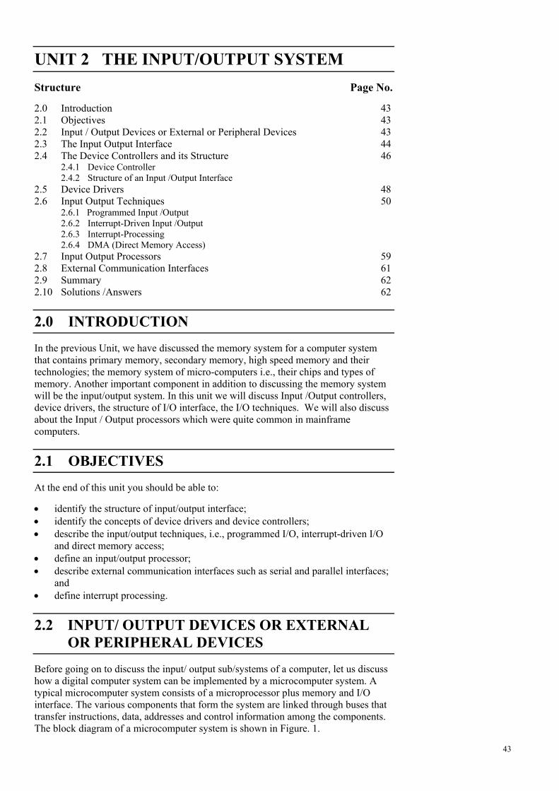
Before going on to discuss the input/ output sub/systems of a computer, let us discuss how a digital computer system can be implemented by a microcomputer system. A typical microcomputer system consists of a microprocessor plus memory and I/O interface. The various components that form the system are linked through buses that transfer instructions, data, addresses and control information among the components. The block diagram of a microcomputer system is shown in Figure. 1.
43
Local Bus
Basic Computer Organisation
(Internal Bus toMotherboard
CPU Main memory (RAM and
CU ALU Cache ROM)
Registers
VideoProcessor
Keyboard
FDD
EISA
VRAM Mouse Display
Device USB & other I/O Buses Scanner
44
Figure 1: Block Diagram of a Microcomputer System The microcomputer has a single microprocessor, a number of RAM and ROM chips and an interface units communicates with various external devices through the I/O Bus.
The Input / Output subsystem of a computer, referred to as I/O, provides an efficient mode of communication between the central system and the output environment. External devices that are under the direct control of the computers are said to be connected on-line. These devices are designed to read information into or out of the memory unit upon command from the CPU and are considered to be part of the computer system. Input / Output devices attached to the computer are also called peripherals. We can broadly classify peripherals or external devices into 3 categories: • Human readable: suitable for communicating with the computer user, e.g., video
display terminals (VDTs) & printers.
• Machine-readable: suitable for communicating with equipment, e.g., magnetic disks and tape system.
• Communication: suitable for communicating with remote devices, e.g., terminal, a machine-readable device.
2.3 THE INPUT /OUTPUT INTERFACE
The Input /Output interface provides a method for transferring information between internal storage and external I/O devices. Peripherals connected to a computer need special communication links for interfacing them with the CPU. The purpose of the
Mouse Digital
CD ROM Printer
camera SCSI
PCI
Additional PrimaryRAM/ROM HDD
LAN/Network
Ethernet ModemLAN Printer
The Input / Output
System communication link is to resolve the differences that exist between the central computer and each peripheral. The major differences are: • Peripherals are electromagnetic and electromechanical devices and their
operations are different from the operation of the CPU and the memory, which are electronic devices.
• The data transfer rate of peripherals is usually slower than the transfer rate of the CPU, and consequently a synchronization mechanism may be needed.
• Data codes and formats in peripherals differ from the word format in the CPU and memory.
• The operating modes of peripherals are different from each other and each must be controlled so as not to disturb the operation of other peripherals connected to the CPU.
To resolve these differences, computer systems include special hardware component between the CPU and peripherals to supervise and synchronize all input and output transfers. These components are called interface units because they interface between the processor bus and the peripheral device. Functions of I/O Interface
An I/O interface is bridge between the processor and I/O devices. It controls the data exchange between the external devices and the main memory; or external devices and processor registers. Therefore, an I/O interface provides an interface internal to the computer which connects it to the processor and main memory and an interface external to the computer connecting it to external device or peripheral. The I/O interface should not only communicate the information from processor to main I/O device, but it should also coordinate these two. In addition, since there are speed differences between processor and I/O devices, the I/O interface should have facilities like buffer and error detection mechanism. Therefore, the major functions or requirements of an I/O interface are:
It should be able to provide control and timing signals
The need of I/O from various I/O devices by the processor is quite unpredictable. In fact it depends on I/O needs of particular programs and normally does not follow any pattern. Since, the I/O interface also shares system bus and memory for data input/output, control and timing are needed to coordinate the flow of data from/to external devices to/from processor or memory. For example, the control of the transfer of data from an external device to the processor might involve the following steps: 1. The processor enquires from the I/O interface to check the status of the attached
device. The status can be busy, ready or out of order.
2. The I/O interface returns the device status.
3. If the device is operational and ready to transmit, the processor requests the transfer of data by means of a command, which is a binary signal, to the I/O interface.
4. The I/O interface obtains a unit of data (e.g., 8 or 16 bits) from the external device.
5. The data is transferred from the I/O interface to the processor. It should communicate with the processor
The above example clearly specifies the need of communication between the processor and I/O interface. This communication involves the following steps:
45
Basic Computer Organisation
1. Commands such as READ SECTOR, WRITE SECTOR, SEEK track number and SCAN record-id sent over the control bus.
2. Data that are exchanged between the processor and I/O interface sent over the data bus.
3. Status: As peripherals are so slow, it is important to know the status of the I/O interface. The status signals are BUSY or READY or in an error condition from I/O interface.
4. Address recognition as each word of memory has an address, so does each I/O device. Thus an I/O interface must recognize one unique address for each peripheral it controls.
It should communicate with the I/O device
Communication between I/O interface and I/O device is needed to complete the I/O operation. This communication involves commands, status or data. It should have a provision for data buffering
Data buffering is quite useful for the purpose of smoothing out the gaps in speed of processor and the I/O devices. The data buffers are registers, which hold the I/O information temporarily. The I/O is performed in short bursts in which data are stored in buffer area while the device can take its own time to accept them. In I/O device to processor transfer, data are first transferred to the buffer and then passed on to the processor from these buffer registers. Thus, the I/O operation does not tie up the bus for slower I/O devices. Error detection mechanism should be in-built
The error detection mechanism may involve checking the mechanical as well as data communication errors. These errors should be reported to the processor. The examples of the kind of mechanical errors that can occur in devices are paper jam in printer, mechanical failure, electrical failure etc. The data communication errors may be checked by using parity bit.
2.4 THE DEVICE CONTROLLERS AND ITS STRUCTURE
All the components of the computer communicate with the processor through the system bus. That means the I/O devices need to be attached to the system bus. However, I/O devices are not connected directly to the computer’s system bus. Instead they are connected to an intermediate electronic device interface called a device controller, which in turn is connected to the system bus. Hence a device controller is an interface between an I/O device and the system bus. On one side, it knows how to communicate with the I/O device connected to it, and on the other it knows how to communicate with the computer’s CPU or processor and memory through the system bus. 2.4.1 Device Controller
A device controller need not necessarily control a single device. It can usually control multiple I/O devices. It comes in the form of an electronic circuit board that plugs directly into the system bus, and there is a cable from the controller to each device it controls. The cables coming out of the controller are usually terminated at the back panel of the main computer box in the form of connectors known as ports.
The Figure 2 below illustrates how I/O devices are connected to a computer system through device controllers. Please note the following points in the diagram:
46
The Input / Output
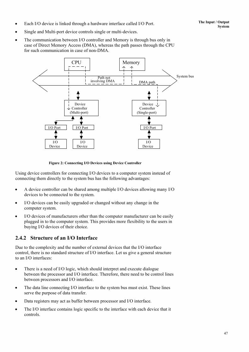
System • Each I/O device is linked through a hardware interface called I/O Port.
• Single and Multi-port device controls single or multi-devices.
• The communication between I/O controller and Memory is through bus only in case of Direct Memory Access (DMA), whereas the path passes through the CPU for such communication in case of non-DMA.
System bus
I/ODevice
I/O Device
I/O Device
I/O PortI/O Port
DeviceController
(Single-port)
I/O Port
Device Controller
(Multi-port)
DMA pathPath not
involving DMA
MemoryCPU
Figure 2: Connecting I/O Devices using Device Controller Using device controllers for connecting I/O devices to a computer system instead of connecting them directly to the system bus has the following advantages: • A device controller can be shared among multiple I/O devices allowing many I/O
devices to be connected to the system.
• I/O devices can be easily upgraded or changed without any change in the computer system.
• I/O devices of manufacturers other than the computer manufacturer can be easily plugged in to the computer system. This provides more flexibility to the users in buying I/O devices of their choice.
2.4.2 Structure of an I/O Interface
Due to the complexity and the number of external devices that the I/O interface control, there is no standard structure of I/O interface. Let us give a general structure to an I/O interfaces: • There is a need of I/O logic, which should interpret and execute dialogue
between the processor and I/O interface. Therefore, there need to be control lines between processors and I/O interface.
• The data line connecting I/O interface to the system bus must exist. These lines serve the purpose of data transfer.
• Data registers may act as buffer between processor and I/O interface.
• The I/O interface contains logic specific to the interface with each device that it controls.
47
Basic Computer Organisation
Figure 3 above iregisters as definstatus informatio
2.5 DEVI
A device driver control of, a speconvert the logicdevice itself. Forrealised within tpresence of a disheads, etc. Device Drivers
Although deviceconsidered to beOutput Control S In UNIX the devcore of the operawas not includedhas to be re-linkadvantages of ruaddition of a newthe /dev directorcommunication below:
48
Figure 3: The General Structure of an I/O
s a typical diagram of an I/O interface which in addition to all the ed above has status/control registers which are used to pass on the n or the control information.
CE DRIVERS
is software interface which manages the communication with, and the cific I/O device, or type of device. It is the task of the device driver to al requests from the user into specific commands directed to the example, a user request to write a record to a floppy disk would be
he device driver as a series of actions, such as checking for the k in the drive, locating the file via the disk directory, positioning the
in UNIX, MS-DOS and Windows System
drivers are in effect add-on modules, they are nevertheless part of the system since they are closely integrated with the Input/ ystem, which deals with I/O related system calls.
ice drivers are usually linked onto the object code of the kernel (the ting system). This means that when a new device is to be used, which in the original construction of the operating system, the UNIX kernel
ed with the new device driver object code. This technique has the n-time efficiency and simplicity, but the disadvantage is that the device requires regeneration of the kernel. In UNIX, each entry in
y is associated with a device driver which manages the with the related device. A list of some device names is as shown
The Input / Output
System Device name Description
/dev/console system console /dev/tty01 user terminal 1 /dev/tty02 user terminal 2 /dev/lp line printer /dev/dsk/f03h 1.44 MB floppy drive In MS-DOS, device drivers are installed and loaded dynamically, i.e., they are loaded into memory when the computer is started or re-booted and accessed by the operating system as required. The technique has the advantage that it makes addition of a new driver much simpler, so that it could be done by relatively unskilled users. The additional merit is that only those drivers which are actually required need to be loaded into the main memory. The device drivers to be loaded are defined in a special file called CONFIG.SYS, which must reside in the root directory. This file is automatically read by MS-DOS at start-up of the system, and its contents acted upon. A list of some device name is as shown below:
Device name Description
con: keyboard/screen com1: serial port1 com2: serial port2 lpt1: printer port1 A: first disk drive C: hard disk drive In the Windows system, device drivers are implemented as dynamic link libraries (DLLs). This technique has the advantages that DLLs contains shareable code which means that only one copy of the code needs to be loaded into memory. Secondly, a driver for a new device can be implemented by a software or hardware vendor without the need to modify or affect the Windows code, and lastly a range of optional drivers can be made available and configured for particular devices. In the Windows system, the idea of Plug and Play device installation is required to add a new device such as a CD drive, etc. The objective is to make this process largely automatic; the device would be attached and the driver software loaded. Thereafter, the installation would be automatic; the settings would be chosen to suit the host computer configuration. Check Your Progress 1
1. What are the functions of an I/O interface? ……………………………………………………………………………………
……………………………………………………………………………………
……………………………………………………………………………………
2. State True or False:
(a) Com1 is a UNIX port. T/F (b) The buffering is done by data register. T/F (c) Device controller is shareable among devices. T/F (d) I/O system is basically needed for better system efficiency T/F (e) Device drives can be provided using software libraries. T/F (f) The devices are normally connected directly to the system bus. T/F (g) Data buffering is helpful for smoothing out the speed differences T/F between CPU and input/output devices. (h) Input/ output module is needed only for slower I/O devices T/F
49
Basic Computer Organisation
3. What is a device driver? Differentiate between device controller and device drivers. ……………………………………………………………………………………
……………………………………………………………………………………
……………………………………………………………………………………
……………………………………………………………………………………
……………………………………………………………………………………
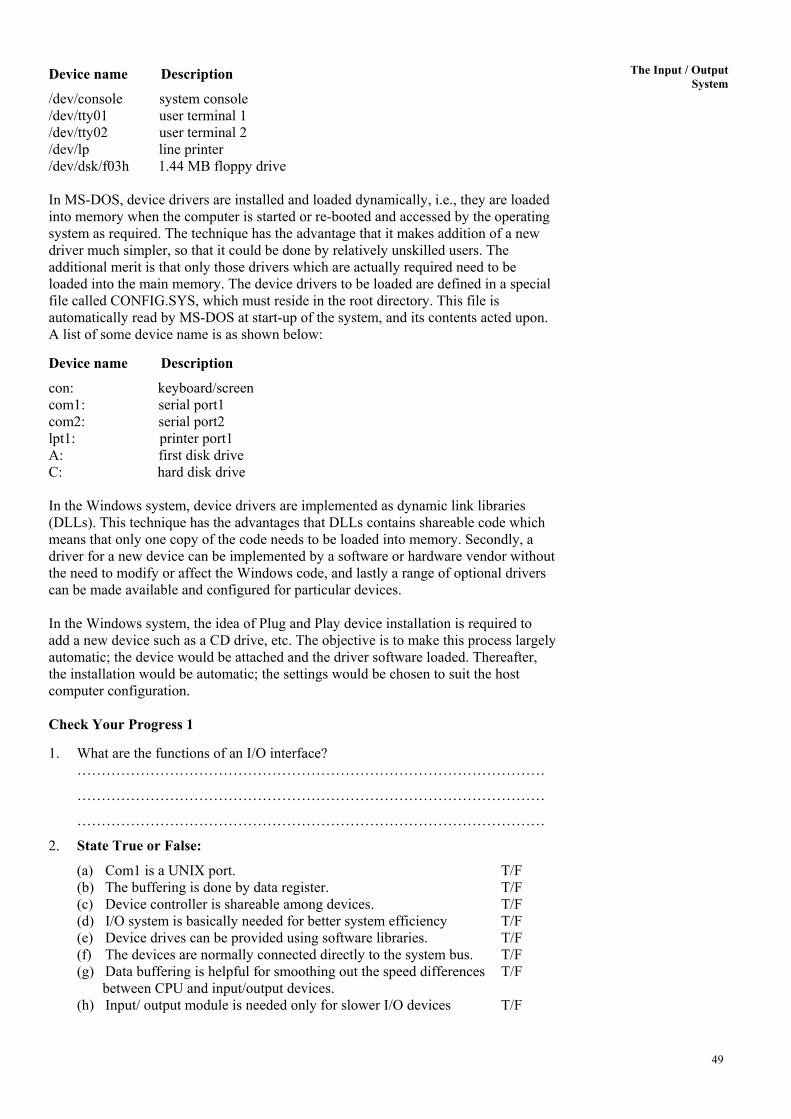
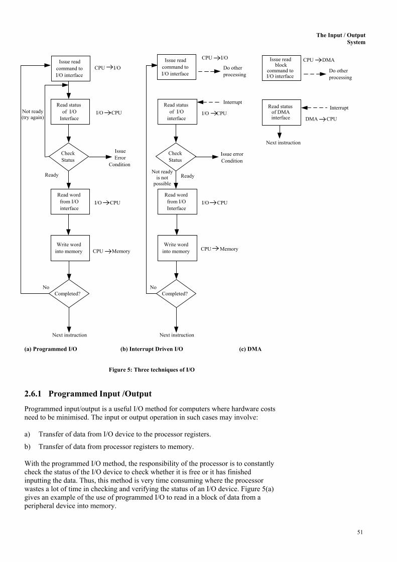
2.6 INPUT-OUTPUT TECHNIQUES After going through the details of the device interfaces, the next point to be discussed is how the interface may be used to support input/output from devices. Binary information received from an external device is usually stored in memory for later processing. Information transferred from the central computer into an external device originates in the memory unit. Data transfer between the central computer and I/O devices may be handled in a variety of modes. Three techniques are possible for I/O operation. These are: • Programmed input/output • Interrupt driven input/output • Direct memory access Figure 4 gives an overview of these three techniques Interrupt
Required I/O interface to/from
memory transfer (refer Figure 2)
Programmed I/O No Through CPU
Interrupt-driven I/O Yes Through CPU
DMA Yes Direct to Memory
In programmeThe processoroperation. It reprocessor sinc With interruptdata transfer, iexternal interrservice prograoriginally perfreduced. With both proextracting dataduring input. Wdata or retriev(DMA). In thiwithout the in
50
Figure 4: Overview of the three Input/ Output
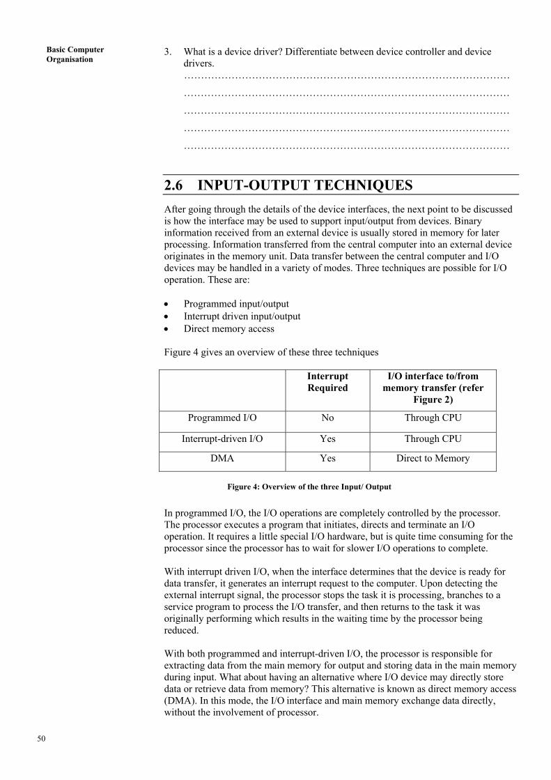
d I/O, the I/O operations are completely controlled by the processor. executes a program that initiates, directs and terminate an I/O quires a little special I/O hardware, but is quite time consuming for the e the processor has to wait for slower I/O operations to complete.
driven I/O, when the interface determines that the device is ready for t generates an interrupt request to the computer. Upon detecting the upt signal, the processor stops the task it is processing, branches to a m to process the I/O transfer, and then returns to the task it was orming which results in the waiting time by the processor being
grammed and interrupt-driven I/O, the processor is responsible for from the main memory for output and storing data in the main memory hat about having an alternative where I/O device may directly store
e data from memory? This alternative is known as direct memory access s mode, the I/O interface and main memory exchange data directly, volvement of processor.
The Input / Output
System CPU I/O Issue read
block command to I/O interface
CPU DMAIssue readcommand toI/O interface
Issue read command to I/O interface
CPU I/O Do other
processing Do otherprocessing
Interrupt Read status of I/O
Interface
Read statusof I/O
interface
Read status of DMA interface
Interrupt
Not ready (try again)
I/O CPU I/O CPUDMA CPU
Next instruction Issue
Error Condition
Check Status
CheckStatus
Issue errorCondition
Not ready
is notpossible
Ready Ready
Read word from I/O interface
Read wordfrom I/OInterface
I/O CPUI/O CPU
Write word into memory
Write wordinto memory CPU Memory Memory CPU
No No Completed? Completed? Next instruction Next instruction (a) Programmed I/O (b) Interrupt Driven I/O (c) DMA
Figure 5: Three techniques of I/O
2.6.1 Programmed Input /Output
Programmed input/output is a useful I/O method for computers where hardware costs need to be minimised. The input or output operation in such cases may involve: a) Transfer of data from I/O device to the processor registers.
b) Transfer of data from processor registers to memory. With the programmed I/O method, the responsibility of the processor is to constantly check the status of the I/O device to check whether it is free or it has finished inputting the data. Thus, this method is very time consuming where the processor wastes a lot of time in checking and verifying the status of an I/O device. Figure 5(a) gives an example of the use of programmed I/O to read in a block of data from a peripheral device into memory.
51
Basic Computer Organisation
I/O Commands
There are four types of I/O commands that an I/O interface may receive when it is addressed by a processor:
• Control: These commands are device specific and are used to provide specific
instructions to the device, e.g. a magnetic tape requiring rewinding and moving forward by a block.
• Test: This command checks the status such as if a device is ready or not or is in error condition.
• Read: This command is useful for input of data from input device. • Write: this command is used for output of data to output device. I/O Instructions:
An I/O instruction is stored in the memory of the computer and is fetched and executed by the processor producing an I/O-related command for the I/O interface. With programmed I/O, there is a close correspondence between the I/O-related instructions and the I/O commands that the processor issues to an I/O interface to execute the instructions.
In systems with programmed I/O, the I/O interface, the main memory and the processors normally share the system bus. Thus, each I/O interface should interpret the address lines to determine if the command is for itself. There are two methods for doing so. These are called memory-mapped I/O and isolated I/O. With memory-mapped I/O, there is a single address space for memory locations and I/O devices. The processor treats the status and data registers of I/O interface as memory locations and uses the same machine instructions to access both memory and I/O devices. For a memory-mapped I/O only a single read and a single write line are needed for memory or I/O interface read or write operations. These lines are activated by the processor for either memory access or I/O device access. Figure 6 shows the memory-mapped I/O system structure.
52
Figure 6: Structure of Memory Mapped I/O
The Input / Output
System With isolated I/O, there are separate control lines for both memory and I/O device read or write operations. Thus a memory reference instruction does not affect an I/O device. In isolated I/O, the I/O devices and memory are addressed separately; hence separate input/output instructions are needed which cause data transfer between addressed I/O interface and processor. Figure 7 shows the structure of isolated I/O.
Figure 7: Structure of Isolated I/O 2.6.2 Interrupt-Driven Input/Output
The problem with programmed I/O is that the processor has to wait a long time for the I/O interface to see whether a device is free or wait till the completion of I/O. The result is that the performance of the processor goes down tremendously. What is the solution? What about the processor going back to do other useful work without waiting for the I/O device to complete or get freed up? But how will the processor be intimated about the completion of I/O or a device is ready for I/O? A well-designed mechanism was conceived for this, which is referred to as interrupt-driven I/O. In this mechanism, provision of interruption of processor work, once the device has finished the I/O or when it is ready for the I/O, has been provided. The interrupt-driven I/O mechanism for transferring a block of data is shown in Figure 5(b). Please note that after issuing a read command (for input) the CPU goes off to do other useful work while I/O interface proceeds to read data from the associated device. On the completion of an instruction cycle, the CPU checks for interrupts (which will occur when data is in data register of I/O interface and it now needs CPU’s attention). Now CPU saves the important register and processor status of the executing program in a stack and requests the I/O device to provide its data, which is placed on the data bus by the I/O device. After taking the required action with the data, the CPU can go back to the program it was executing before the interrupt. 2.6.3 Interrupt-Processing
The occurrence of an interrupt fires a numbers of events, both in the processor hardware and software. Figure 8 shows a sequence.
53
Basic Computer Organisation
Figure 8: Interrupt-Processing Sequence When an I/O device completes an I/O operation, the following sequence of hardware events occurs: 1. The device issues an interrupt signal to the processor.
2. The processor finishes execution of the current instruction before responding to the interrupt.
3. The processor tests for the interrupts and sends an acknowledgement signal to the device that issued the interrupt.
4. The minimum information required to be stored for the task being currently executed, before the CPU starts executing the interrupt routine (using its registers) are:
(a) The status of the processor, which is contained in the register called program status word (PSW), and
(b) The location of the next instruction to be executed, of the currently executing program, which is contained in the program counter (PC).
54
The Input / Output
System 5. Th e processor now loads the PC with the entry location of the interrupt-handling
program that will respond to this interrupting condition. Once the PC has been loaded, the processor proceeds to execute the next instruction, that is the next instruction cycle, which begins with an instruction fetch. Because the instruction fetch is determined by the contents of the PC, the result is that control is transferred to the interrupt-handler program. The execution results in the following operations:
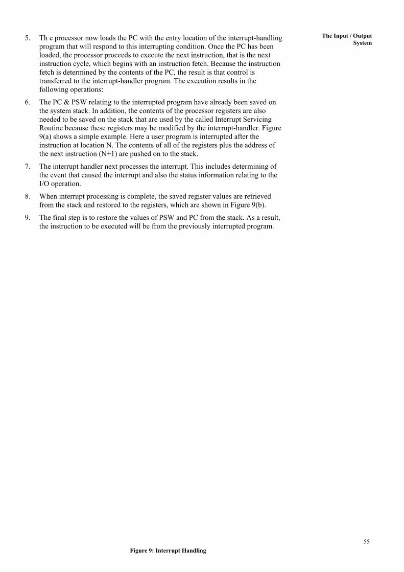
6. The PC & PSW relating to the interrupted program have already been saved on the system stack. In addition, the contents of the processor registers are also needed to be saved on the stack that are used by the called Interrupt Servicing Routine because these registers may be modified by the interrupt-handler. Figure 9(a) shows a simple example. Here a user program is interrupted after the instruction at location N. The contents of all of the registers plus the address of the next instruction (N+1) are pushed on to the stack.
7. The interrupt handler next processes the interrupt. This includes determining of the event that caused the interrupt and also the status information relating to the I/O operation.
8. When interrupt processing is complete, the saved register values are retrieved from the stack and restored to the registers, which are shown in Figure 9(b).
9. The final step is to restore the values of PSW and PC from the stack. As a result, the instruction to be executed will be from the previously interrupted program.
55Figure 9: Interrupt Handling
Basic Computer Organisation
Thus, interrupt handling involves interruption of the currently executing program, execution of interrupt servicing program and restart of interrupted program from the point of interruption. Design issues: Two design issues arise in implementing interrupt-driven I/O: 1) How does the processor determine which device issued the interrupt?
2) If multiple interrupts have occurred, how does the processor decide which one to be processed first?
To solve these problems, four general categories of techniques are in common use: • Multiple Interrupt Lines: The simplest solution to the problems above is to
provide multiple interrupt lines, which will result in immediate recognition of the interrupting device. Priorities can be assigned to various interrupts and the interrupt with the highest priority should be selected for service in case a multiple interrupt occurs. But providing multiple interrupt lines is an impractical approach because only a few lines of the system bus can be devoted for the interrupt.
• Software Poll: In this scheme, on the occurrence of an interrupt, the processor jumps to an interrupt service program or routine whose job it is to poll (roll call) each I/O interface to determine which I/O interface has caused the interrupt. This may be achieved by reading the status register of the I/O interface. Once the correct interface is identified, the processor branches to a device-service routine specific to that device. The disadvantage of the software poll is that it is time consuming.
• Daisy chain: This scheme provides a hardware poll. With this technique, an interrupt acknowledge line is chained through various interrupt devices. All I/O interfaces share a common interrupt request line. When the processor senses an interrupt, it sends out an interrupt acknowledgement. This signal passes through all the I/O devices until it gets to the requesting device. The first device which has made the interrupt request thus senses the signal and responds by putting in a word which is normally an address of interrupt servicing program or a unique identifier on the data lines. This word is also referred to as interrupt vector. This address or identifier in turn is used for selecting an appropriate interrupt-servicing program. The daisy chaining has an in-built priority scheme, which is determined by the sequence of devices on interrupt acknowledge line.
• Bus arbitration: In this scheme, the I/O interface first needs to control the bus and only after that it can request for an interrupt. In this scheme, since only one of the interfaces can control the bus, therefore only one request can be made at a time. The interrupt request is acknowledged by the CPU on response of which I/O interface places the interrupt vector on the data lines. An interrupt vector normally contains the address of the interrupt serving program.
An example of an interrupt vector can be a personal computer, where there are several IRQs (Interrupt request) for a specific type of interrupt. 2.6.4 DMA (Direct Memory Access)
In both interrupt-driven and programmed I/O, the processor is busy with executing input/output instructions and the I/O transfer rate is limited by the speed with which the processor can test and service a device. What about a technique that requires minimal intervention of the CPU for input/output? These two types of drawbacks can be overcome with a more efficient technique known as DMA, which acts as if it has taken over control from the processor. Hence, the question is: why do we use DMA interface? It is used primarily when a large amount of data is to be transferred from the I/O device to the Memory.
56
The Input / Output
System DMA Function
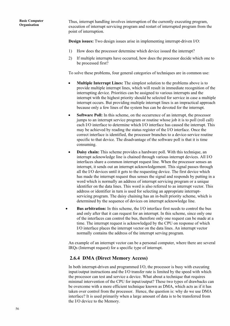
Although the CPU intervention in DMA is minimised, yet it must use the path between interfaces that is the system bus. Thus, DMA involves an additional interface on the system bus. A technique called cycle stealing allows the DMA interface to transfer one data word at a time, after which it must return control of the bus to the processor. The processor merely delays its operation for one memory cycle to allow the directly memory I/O transfer to “steal” one memory cycle. When an I/O is requested, the processor issues a command to the DMA interface by sending to the DMA interface the following information (Figure 10): • Which operations (read or write) to be performed, using the read or write control
lines.
• The address of I/O devices, which is to be used, communicated on the data lines.
• The starting location on the memory where the information will be read or written to be communicated on the data lines and is stored by the DMA interface in its address register.
• The number of words to be read or written is communicated on the data lines and is stored in the data count register.
Figure 10: DMA block diagram
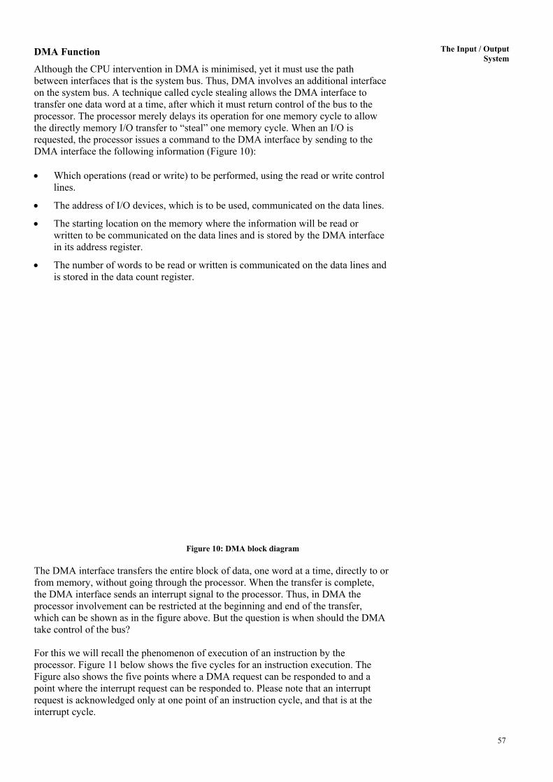
The DMA interface transfers the entire block of data, one word at a time, directly to or from memory, without going through the processor. When the transfer is complete, the DMA interface sends an interrupt signal to the processor. Thus, in DMA the processor involvement can be restricted at the beginning and end of the transfer, which can be shown as in the figure above. But the question is when should the DMA take control of the bus? For this we will recall the phenomenon of execution of an instruction by the processor. Figure 11 below shows the five cycles for an instruction execution. The Figure also shows the five points where a DMA request can be responded to and a point where the interrupt request can be responded to. Please note that an interrupt request is acknowledged only at one point of an instruction cycle, and that is at the interrupt cycle.
57
Basic Computer Organisation
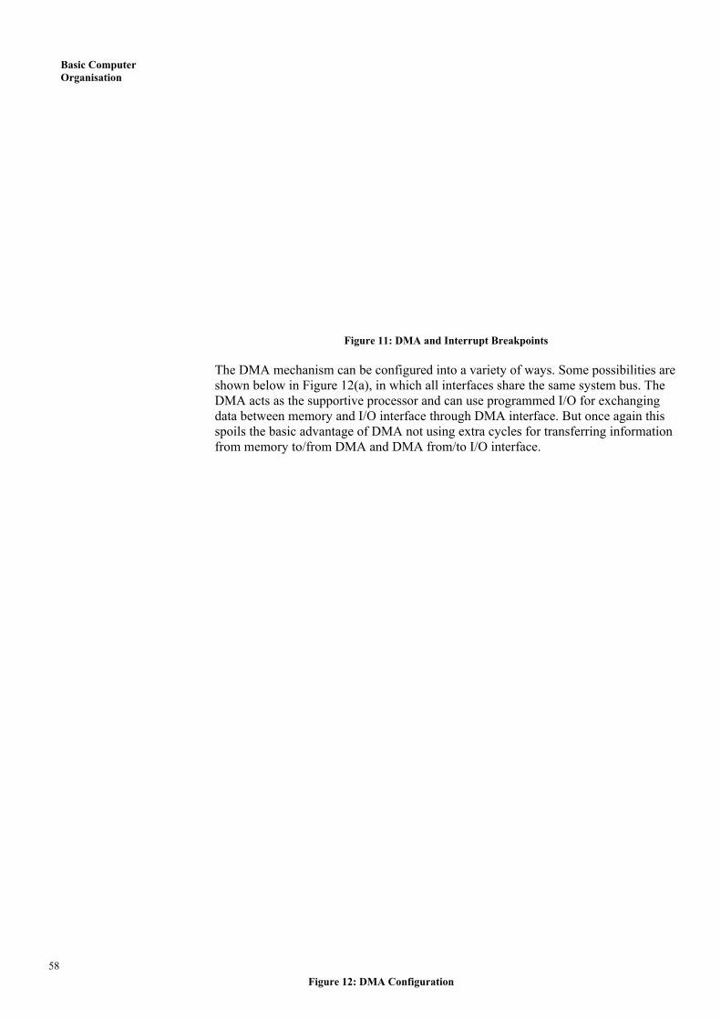
Figure 11: DMA and Interrupt Breakpoints The DMA mechanism can be configured into a variety of ways. Some possibilities are shown below in Figure 12(a), in which all interfaces share the same system bus. The DMA acts as the supportive processor and can use programmed I/O for exchanging data between memory and I/O interface through DMA interface. But once again this spoils the basic advantage of DMA not using extra cycles for transferring information from memory to/from DMA and DMA from/to I/O interface.
58 Figure 12: DMA Configuration
The Input / Output
System The Figure 12(b) configuration suggests advantages over the one shown above. In these systems a path is provided between I/O interface and DMA interface, which does not include the system bus. The DMA logic may become part of an I/O interface and can control one or more I/O interfaces. In an extended concept an I/O bus can be connected to this DMA interface. Such a configuration (shown in Figure 12 (c)) is quite flexible and can be extended very easily. In both these configurations, the added advantage is that the data between I/O interface and DMA interface is transferred off the system bus, thus eliminating the disadvantage we have witnessed for the first configuration. Check Your Progress 2 1. Which of the I/O techniques does not require an Interrupt Signal? Is this
technique useful in Multiprogramming Operating Systems? Give reason.
……………………………………………………………………………………
……………………………………………………………………………………
……………………………………………………………………………………
2. What are the techniques of identifying the device that has caused the Interrupt?
……………………………………………………………………………………
……………………………………………………………………………………
……………………………………………………………………………………
3. What are the functions of I/O interface? What is DMA? ……………………………………………………………………………………
……………………………………………………………………………………
……………………………………………………………………………………
4 State True or False:
a) Daisy chain provides software poll. T/F
b) I/O mapped I/O scheme requires no additional lines from CPU to I/O device except for the system bus. T/F
c) Most of the I/O processors have their own memory while a DMA module does not have its own memory except for a register or a simple buffer area.
T/F
d) The advantage of interrupt driven I/O over programmed I/O is that in the first the interrupt mechanisms free I/O devices quickly. T/F
2.7 INPUT-OUTPUT PROCESSORS
Before discussing I/O processors, let us briefly recapitulate the development in the area of input/output functions. These can be summarised as: 1. The CPU directly controls a peripheral device.
2. Addition of I/O controller or I/O interface: The CPU uses programmed I/O without interrupts. CPU was separated from the details of external I/O interfaces.
3. Contained use of I/O controllers but with interrupts: The CPU need not spend time waiting for an I/O operation to be performed, increasing efficiency.
4. Direct access of I/O interface to the memory via DMA: CPU involvement reduced to at the beginning and at the end of DMA operation.
59
Basic Computer Organisation
5. The CPU directs the I/O processors to execute an I/O program in memory. The I/O processor fetches and executes these instructions without CPU intervention. This allows the CPU to specify a sequence of I/O activities and to be interrupted only when the entire sequence has been performed. With this architecture, a large set of I/O devices can be controlled, with minimum CPU involvement.
With the last two steps (4 and 5), a major change occurs with the introduction of the concept of an I/O interface capable of executing a program. For steps 5, the I/O interface is often referred to as an I/O channel and I/O processor. Characteristics of I/O Channels
The I/O channel represents an extension of the DMA concept. An I/O channel has the ability to execute I/O instructions, which gives complete control over the I/O operation. With such devices, the CPU does not execute I/O instructions. Such instructions are stored in the main memory to be executed by a special-purpose processor in the I/O channel itself. Thus, the CPU initiates an I/O transfer by instructing the I/O channel to execute a program in memory. Two types of I/O channels are commonly used which can be seen in Figure 13 (a and b).
(a) Selector Channel (b) Multiplexer Channel
Figure 13: I/O Channel Structures 60
The Input / Output
System A selector channel controls multiple high-speed devices and, at any one time, is dedicated to the transfer of data with one of those devices. Each device is handled by a controller or I/O interface. Thus the I/O channel serves in place of the CPU in controlling these I/O controllers. A multiplexer channel can handle I/O with multiple devices at the same time. If the devices are slow then byte multiplexer is used. Let us explain this with an example. If we have three slow devices which need to send individual bytes as:
X1 X2 X3 X4 X5 …… Y1 Y2 Y3 Y4 Y5…… Z1 Z2 Z3 Z4 Z5…… Then on a byte multiplexer channel they may send the bytes as X1 Y1 Z1 X2 Y2 Z2 X3 Y3 Z3…… For high-speed devices, blocks of data from several devices are interleaved. These devices are called block multiplexer.
2.8 EXTERNAL COMMUNICATION INTERFACES
The external interface is the interface between the I/O interface and the peripheral devices. This interface can be characterised into two main categories: (a) parallel interface and (b) serial interface. In parallel interface multiple bits can be transferred simultaneously. The parallel interface is normally used for high-speed peripherals such as tapes and disks. The dialogues that take place across the interface include the exchange of control information and data. In serial interface only one line is used to transmit data, therefore only one bit is transferred at a time. Serial printers are used for serial printers and terminals. With a new generation of high-speed serial interfaces, parallel interfaces are becoming less common. In both cases, the I/O interface must engage in a dialogue with the peripheral. The dialogue for a read or write operation is as follows: • A control signal is sent by I/O interface to the peripheral requesting the
permission to send (for write) or receive (for read) data.
• The peripheral acknowledges the request.
• The data are transferred from I/O interface to peripheral (for write) or from peripheral to I/O interface (for read).
• The peripheral acknowledges receipt of the data. The connection between an I/O interface in a computer system and external devices can be either point-to-point or multipoint. A point-to-point interface provides a dedicated line between the I/O interface and the external device. For example keyboard, printer and external modems are point-to-point links. The most common serial interfaces are RS-232C and EIA-232. A multipoint external interface used to support external mass storage devices (such as disk and tape drives) and multimedia devices (such as CD-ROM, video, audio). Two important examples of external interfaces are FireWire and InfiniBand.
61
Basic Computer Organisation
Check Your Progress 3 1. What is the need of I/O channels?
……………………………………………………………………………………
……………………………………………………………………………………
……………………………………………………………………………………
……………………………………………………………………………………
2. What is the need of external Communication Interfaces? ……………………………………………………………………………………
……………………………………………………………………………………
……………………………………………………………………………………
……………………………………………………………………………………
2.9 SUMMARY
This unit is totally devoted to the I/O of computer system. In this unit we have discussed the identification of I/O interface, description of I/O techniques such as programmed I/O, interrupt-driven I/O and direct memory access. These techniques are useful for increasing the efficiency of the input-output transfer process. The concepts of device drivers for all types of operating systems and device controllers are also discussed with this unit. We have also defined an input/output processor, the external communication interfaces such as serial and parallel interfaces and interrupt processing. The I/O processors are the most powerful I/O interfaces that can execute the complete I/O instructions. You can always refer to further reading for detail design.
2.10 SOLUTIONS /ANSWERS
Check Your Progress 1 1. The functions of I/O interfaces are to provide:
• Timing and control signal.
• Communication with processor and I/O devices.
• Support for smoothing the speed gap between CPU and Memory using buffering.
• Error detection.
2. (a) False (b) True (c) True (d) True (e) True (f) False (g) True (h) False 3. A device driver is a software module which manages the communication with,
and the control of, a specific I/O device, or type of device. The difference between device driver and controller are: • One device controller can control many devices, whereas drivers are device
specific.
• Device controllers are a more intelligent hardware-software combination than device drivers.
• I/O controllers allow different types and upgradeability of devices whereas device driver is device specific.
62
63
The Input / Output System
Check Your Progress 2 1. The technique Programmed I/O does not require an Interrupt. It is very inefficient
for Multiprogramming environment as the processor is busy waiting for the I/O to complete, while this time would have been used for instruction execution of other programs.
2. The techniques for recognition of interrupting device/conditions can be:
• Multiple Interrupt Lines: Having separate line for a device, thus direct recognition.
• Software Poll: A software driven roll call to find from devices whether it has made an interrupt request.
• Daisy Chain: A hardware driven passing the buck type signal that moves through the devices connected serially. The device on receipt of signal on his turn, if has interrupt informs its address.
• Bus Arbitration: In this scheme, the I/O interface requests for control of the Bus. This is a common process when I/O processors are used.
3. The functions of I/O interface are:
• Control and timing signals
• CPU communications
• I/O device communication
• Data buffering
• In-built error-detection mechanism.
DMA is an I/O technique that minimises the CPU intervention at the beginning and end of a time consuming I/O. One, commonplace where DMA is used is when I/O is required from a Hard Disk, since one single I/O request requires a block of data transfer which on the average may take a few milliseconds. Thus, DMA will free CPU to do other useful tasks while I/O is going on.
4. a) False b) False c) True d) False Check Your Progress 3 1. The I/O channels were popular in older mainframes, which included many I/O
devices and I/O requests from many users. The I/O channel takes control of all I/O instructions from the main processor and controls the I/O requests. It is mainly needed in situations having many I/O devices, which may be shared among multiple users.
2. The external interfaces are the standard interfaces that are used to connect third party or other external devices. The standardization in this area is a must.