unit 4 transaction management unit 4 contents at a …database management systems 3 each...
TRANSCRIPT

DATABASE MANAGEMENT SYSTEMS
1
UNIT 4
TRANSACTION MANAGEMENT
Unit 4 contents at a glance: Transaction Management:
Transaction concept,
transaction state,
implementation of atomicity and durability,
concurrent executions,
Anomalies due to interleaved execution of transactions,
serializability,
recoverability,
implementation of isolation Concurrency control and recovery system:
Concurrency control : o lock based protocols, o time stamp based protocols, o validation based protocols, o deadlock handling.
Recovery system : o failure classification, o recovery and atomicity, o log -based recovery, shadow paging, o recovery with concurrent transactions, o ARIES algorithm
Transaction:
It refers to execution of any one user program in dbms.
(Or)
It can be defined as group of tasks being executed.
(Or)
It also referred to as an event that which occur on a database with read/write operation.
DATABASE MANAGEMENT SYSTEMS
2
PROPERTIES OF TRANSACTION(ACID PROPERTIES):
To ensure consistency , completeness of the database in scenario of concurrent access, system
failure ,the following ACID properties can be enforced on to database.
1. Atomicity,
2. Consistency,
3. Isolation and
4. Durability
Atomicity:
This property states that all of the instructions with in a transaction must be executed or none
of them should be executed.
This property states that all transactions execution must be atomic i.e. all actions should be
carried out or none of the actions should be executed.
It involves following two operations. —Abort: If a transaction aborts, changes made to database are not visible. —Commit: If a transaction commits, changes made are visible. Atomicity is also known as the ‘All or nothing rule’. Example:
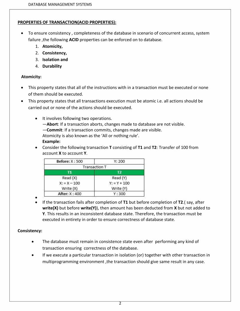
Consider the following transaction T consisting of T1 and T2: Transfer of 100 from account X to account Y.
If the transaction fails after completion of T1 but before completion of T2.( say, after
write(X) but before write(Y)), then amount has been deducted from X but not added to Y. This results in an inconsistent database state. Therefore, the transaction must be executed in entirety in order to ensure correctness of database state.
Consistency:
The database must remain in consistence state even after performing any kind of
transaction ensuring correctness of the database.
If we execute a particular transaction in isolation (or) together with other transaction in
multiprogramming environment ,the transaction should give same result in any case.
DATABASE MANAGEMENT SYSTEMS
3
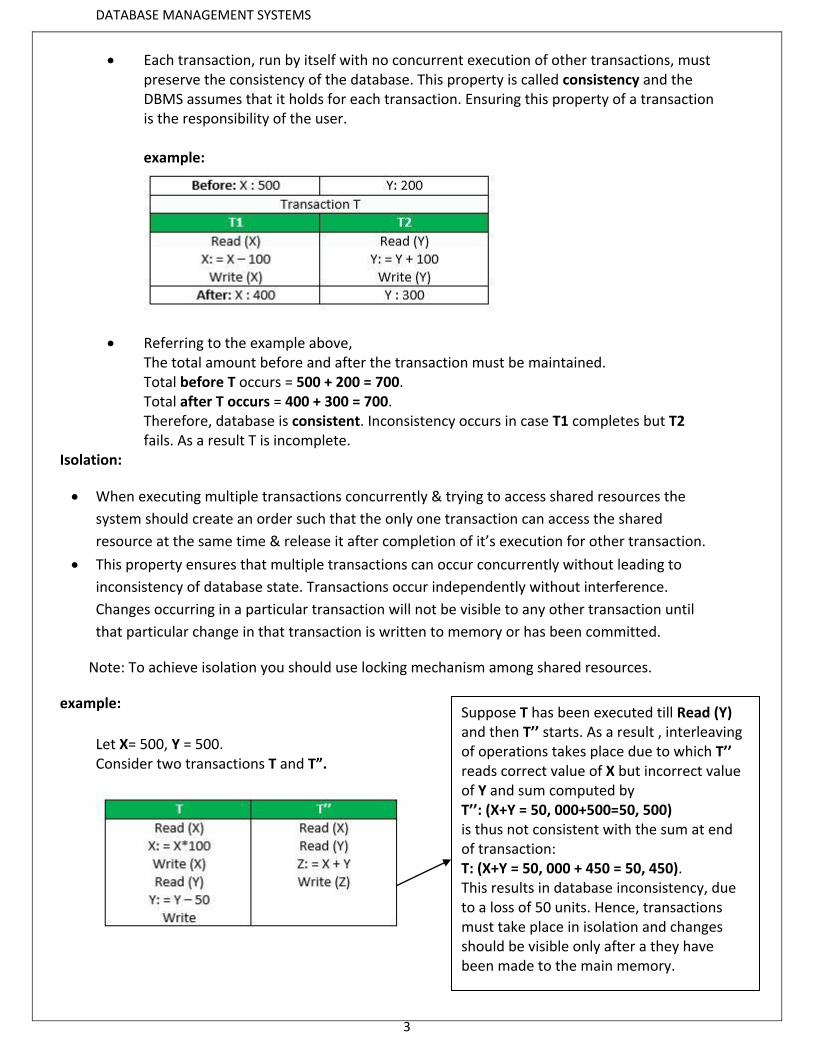
Each transaction, run by itself with no concurrent execution of other transactions, must preserve the consistency of the database. This property is called consistency and the DBMS assumes that it holds for each transaction. Ensuring this property of a transaction is the responsibility of the user. example:
Referring to the example above, The total amount before and after the transaction must be maintained. Total before T occurs = 500 + 200 = 700. Total after T occurs = 400 + 300 = 700. Therefore, database is consistent. Inconsistency occurs in case T1 completes but T2 fails. As a result T is incomplete.
Isolation:
When executing multiple transactions concurrently & trying to access shared resources the
system should create an order such that the only one transaction can access the shared
resource at the same time & release it after completion of it’s execution for other transaction.
This property ensures that multiple transactions can occur concurrently without leading to
inconsistency of database state. Transactions occur independently without interference.
Changes occurring in a particular transaction will not be visible to any other transaction until
that particular change in that transaction is written to memory or has been committed.
Note: To achieve isolation you should use locking mechanism among shared resources.
example:
Let X= 500, Y = 500. Consider two transactions T and T”.
Suppose T has been executed till Read (Y) and then T’’ starts. As a result , interleaving of operations takes place due to which T’’ reads correct value of X but incorrect value of Y and sum computed by T’’: (X+Y = 50, 000+500=50, 500) is thus not consistent with the sum at end of transaction: T: (X+Y = 50, 000 + 450 = 50, 450). This results in database inconsistency, due to a loss of 50 units. Hence, transactions must take place in isolation and changes should be visible only after a they have been made to the main memory.
DATABASE MANAGEMENT SYSTEMS
4
Durability:
This property states that once after the transaction is completed the changes that made should
be permanent & should be recoverable even after system crash/power failure.
This property ensures that once the transaction has completed execution, the updates and
modifications to the database are stored in and written to disk and they persist even is system
failure occurs. These updates now become permanent and are stored in a non-volatile
memory.
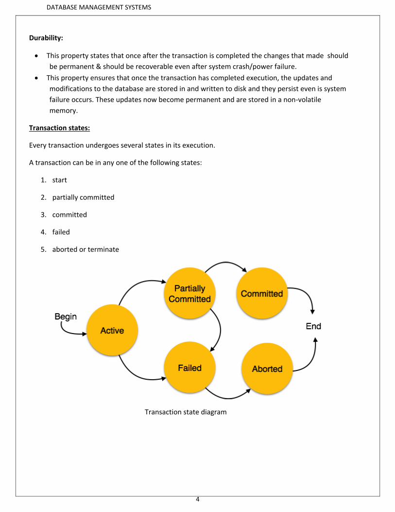
Transaction states:
Every transaction undergoes several states in its execution.
A transaction can be in any one of the following states:
1. start
2. partially committed
3. committed
4. failed
5. aborted or terminate
Transaction state diagram
DATABASE MANAGEMENT SYSTEMS
5
Active - This is the first state of transaction and here the transaction is being executed. For
example, updating or inserting or deleting a record is done here. But it is still not
saved to the database. When we say transaction it will have set of small steps, and
those steps will be executed here.
Partially Committed - This is also an execution phase where last step in the transaction is
executed. But data is still not saved to the database. In example of calculating total
marks, final display the total marks step is executed in this state.
Committed - In this state, all the transactions are permanently saved to the database. This step
is the last step of a transaction, if it executes without fail.
Failed - If a transaction cannot proceed to the execution state because of the failure of the
system or database, then the transaction is said to be in failed state. In the total mark
calculation example, if the database is not able fire a query to fetch the marks, i.e.;
very first step of transaction, then the transaction will fail to execute.
Aborted - If a transaction is failed to execute, then the database recovery system will make sure
that the database is in its previous consistent state. If not, it brings the database to
consistent state by aborting or rolling back the transaction. If the transaction fails in
the middle of the transaction, all the executed transactions are rolled back to it
consistent state before executing the transaction. Once the transaction is aborted it is
either restarted to execute again or fully killed by the DBMS.
Implementation of Durability & Atomicity:
Durability and atomicity can be ensured by using Recovery manager which is available by default in
every DBMS.
We can implement atomicity by using
1. Shadow copying technique
2. Using recovery manager which available by default in DBMS.
DATABASE MANAGEMENT SYSTEMS
6
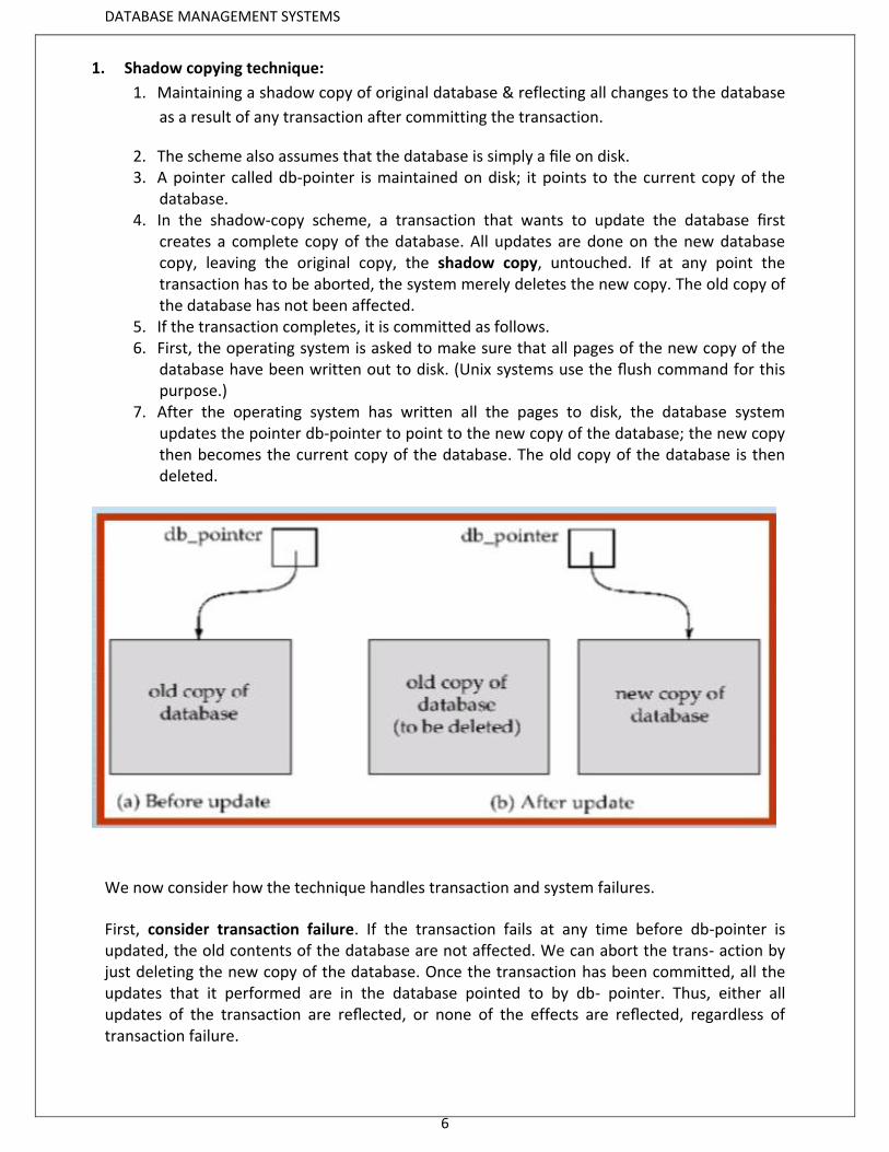
1. Shadow copying technique:
1. Maintaining a shadow copy of original database & reflecting all changes to the database
as a result of any transaction after committing the transaction.
2. The scheme also assumes that the database is simply a file on disk. 3. A pointer called db-pointer is maintained on disk; it points to the current copy of the
database. 4. In the shadow-copy scheme, a transaction that wants to update the database first
creates a complete copy of the database. All updates are done on the new database copy, leaving the original copy, the shadow copy, untouched. If at any point the transaction has to be aborted, the system merely deletes the new copy. The old copy of the database has not been affected.
5. If the transaction completes, it is committed as follows. 6. First, the operating system is asked to make sure that all pages of the new copy of the
database have been written out to disk. (Unix systems use the flush command for this purpose.)
7. After the operating system has written all the pages to disk, the database system updates the pointer db-pointer to point to the new copy of the database; the new copy then becomes the current copy of the database. The old copy of the database is then deleted.
We now consider how the technique handles transaction and system failures.
First, consider transaction failure. If the transaction fails at any time before db-pointer is updated, the old contents of the database are not affected. We can abort the trans- action by just deleting the new copy of the database. Once the transaction has been committed, all the updates that it performed are in the database pointed to by db- pointer. Thus, either all updates of the transaction are reflected, or none of the effects are reflected, regardless of transaction failure.
DATABASE MANAGEMENT SYSTEMS
7
Now consider the issue of system failure. Suppose that the system fails at any time before the updated db-pointer is written to disk. Then, when the system restarts, it will read db-pointer and will thus see the original contents of the database, and none of the effects of the transaction will be visible on the database. Next, suppose that the system fails after db-pointer has been updated on disk. Before the pointer is updated, all updated pages of the new copy of the database were written to disk. Again, we assume that, once a file is written to disk, its contents will not be damaged even if there is a system failure. Therefore, when the system restarts, it will read db-pointer and will thus see the contents of the database after all the updates performed by the transaction.
**WE CAN IMPLEMENT DURABILITY AMONG DATA BASE USING :
1. Recovery manager.
2. Logs
Partial transaction should be avoided for ensuring atomicity and durability.
LOGS:
Logs keep track of actions carried out by transactions which can be used for the
recovery of database in case of failure.
Logs files should be stored always on stable storage devices.
When a transaction begins its execution it is recorded in the log as follows
<Tn, start>
When a transaction performs an operation it is recorded in log as follows
<Tn, X, V1, V2>
When a transaction finishes it’s execution, it is recorded as
<Tn,commit>
DATABASE MANAGEMENT SYSTEMS
8
CONCURRENT EXECUTION:
Executing a set of transactions simultaneously in a pre emptive and time shared method.
In DBMS concurrent execution of transaction can be implemented with interleaved
execution.
TRANSACTION SCHEDULES:
Schedule:
It refers to the list of actions to be executed by transaction.
A schedule is a process of grouping the transactions into one and executing them in a
predefined order.
Schedule of actions can be classified into 2 types.
1. Serializable schedule/serial schedule.
2. Concurrent schedule.
1. Serial schedule:
In the serial schedule the transactions are allowed to execute one after the other ensuring
correctness of data.
A schedule is called serial schedule, if the transactions in the schedule are defined to execute one
after the other.
2. Concurrent schedule:
Concurrent schedule allows the transaction to be executed in interleaved manner of execution.
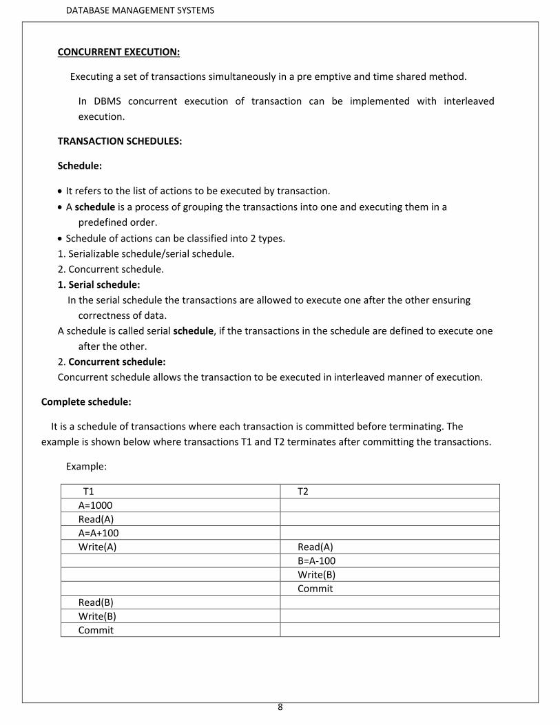
Complete schedule:
It is a schedule of transactions where each transaction is committed before terminating. The
example is shown below where transactions T1 and T2 terminates after committing the transactions.
Example:
T1 T2
A=1000
Read(A)
A=A+100
Write(A) Read(A)
B=A-100
Write(B)
Commit
Read(B)
Write(B)
Commit
DATABASE MANAGEMENT SYSTEMS
9
SERIALIZABILITY:
A transaction is said to be Serializable if it is equivalent to serial schedule.
Serializability aspects are:
1. Conflict serializability.
2. View serializability.
1. Conflict serializability:
A schedule is conflict serializable if it is conflict equivalent to some serial schedule.
Conflict Equivalent: Two schedules are said to be conflict equivalent when one can be
transformed to another by swapping non-conflicting operations.
Conflict Serializable: A schedule is called conflict serializable if it can be transformed into a serial schedule by swapping non-conflicting operations.
Conflicting operations: Two operations are said to be conflicting if all below conditions are satisfied:
They belong to different transaction They operation on same data item At Least one of them is a write operation
it refers to two instructions of two different transactions may want to access same data to
perform read/write operation.
Rules for conflict serializability:
If two different transactions are both for read operation, then there is no conflict and
can allowed to execute any order.
If one instruction performing read operation and other instruction performing write
operation there will be conflict hence instruction ordering is important.
If both transactions performing write operation then there will be in conflict so ordering
the transaction can be done.

DATABASE MANAGEMENT SYSTEMS
10
2. View serializability:
This is another type of serializability that can be derived by creating another schedule out of an
existing Schedule.
A schedule is view serializable if it is view equivalent to some serial schedule. Every conflict serializable schedule is view serializable, although the converse is not true.
Two schedules S1 and S2 over the same set of transactions --any transaction that appears in either S1 or S2 must also appear in the other are view equivalent under these conditions: 1. If Ti reads the initial value of object A in S1, it must also read the initial value of A in S2. 2. If Ti reads a value of A written by Tj in S1, it must also read the value of A written by Tj in S2. 3. For each data object A, the transaction (if any) that performs the final write on A in S1 must also perform the final write on A in S2.
The above two schedules are view serializable or view equivalence, if the transactions in both
schedules performs the actions in similar manner.
The above two schedules satisfy result view equivalence if the two schedule produces the same
Result after execution.
Ex:
s1:R1(A),W1(A),R2(A),W2(A),R1(B),W1(B),R2(B),W2(B)

DATABASE MANAGEMENT SYSTEMS
11
Anomalies due to interleave execution of transaction:
Due to interleaved execution of transaction the following anomalies can occur
1. reading uncommitted values(WR conflicts)
2. un repeatable reading data operation(RW conflicts)
3. Overwriting uncommitted data(WW )
1. reading uncommitted values(WR conflicts):
If you try to the read the value which is not written on to the data base(not
committed) will leads to write-read conflict which is called dirty read operation.
In above example, T1 write operation on data item A is not committed but it is being read by
T2. So reading an uncommitted data will leads to inconsistency in database which is called dirty
read operation.
2. un repeatable reading data operation(RW conflicts):
Reading the same object twice before committing the transaction might yield an inconsistency
–Read-then-Write (RW) Conflicts (Write-After-Read)
Unrepeatable problem means we get different values in different reads. For example in S1 say
T2 read initially x=5 then T1 updated x=1 so now T2 will read x=1 here T2 has read two
different values during consecutive reads This shouldn't have been allowed as T1 has not
committed
DATABASE MANAGEMENT SYSTEMS
12
3. Overwriting uncommitted data(WW conflicts)
WW conflicts if one transaction could over write the value of an object A which has
been already modified by other transaction while first transaction still in progress .this kind of
conflict refer to blind write conflict.
Recoverability:
It refers to the process of undoing the changes made to the database in case of any transaction
failure due to system crash or any other reason.
Recoverability Schedule:
Based on whether recovery of failure transaction schedules are classified as
1. Irrecoverable schedules.
2. Recoverable schedules with cascade rollback.
3. Cascade less recoverability.
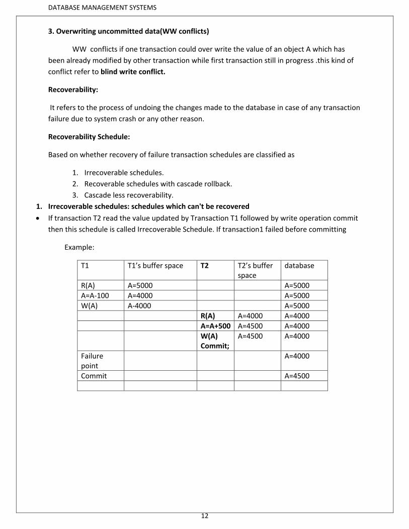
1. Irrecoverable schedules: schedules which can't be recovered
If transaction T2 read the value updated by Transaction T1 followed by write operation commit
then this schedule is called Irrecoverable Schedule. If transaction1 failed before committing
Example:
T1 T1’s buffer space T2 T2’s buffer space
database
R(A) A=5000 A=5000
A=A-100 A=4000 A=5000
W(A) A-4000 A=5000
R(A) A=4000 A=4000
A=A+500 A=4500 A=4000
W(A) Commit;
A=4500 A=4000
Failure point
A=4000
Commit A=4500
DATABASE MANAGEMENT SYSTEMS
13
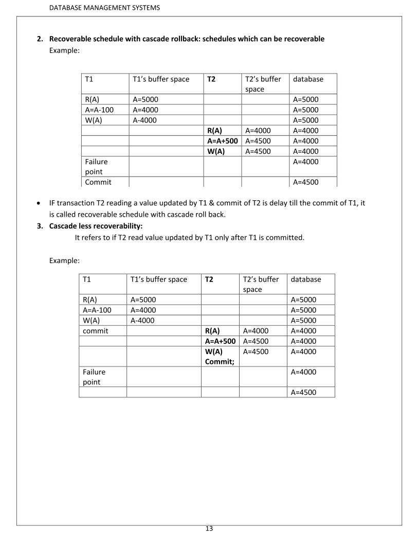
2. Recoverable schedule with cascade rollback: schedules which can be recoverable
Example:
IF transaction T2 reading a value updated by T1 & commit of T2 is delay till the commit of T1, it
is called recoverable schedule with cascade roll back.
3. Cascade less recoverability:
It refers to if T2 read value updated by T1 only after T1 is committed.
Example:
T1 T1’s buffer space T2 T2’s buffer space
database
R(A) A=5000 A=5000
A=A-100 A=4000 A=5000
W(A) A-4000 A=5000
commit R(A) A=4000 A=4000
A=A+500 A=4500 A=4000
W(A) Commit;
A=4500 A=4000
Failure point
A=4000
A=4500
T1 T1’s buffer space T2 T2’s buffer space
database
R(A) A=5000 A=5000
A=A-100 A=4000 A=5000
W(A) A-4000 A=5000
R(A) A=4000 A=4000
A=A+500 A=4500 A=4000
W(A) A=4500 A=4000
Failure point
A=4000
Commit A=4500
DATABASE MANAGEMENT SYSTEMS
14
Implementation of Isolation:
When more than one instruction of several transaction are being executed concurrently
by using some sharable resources , the execution of instruction of one transaction
should not interrupted the execution of instruction of anther transaction.
1. Access to sharable resources should be order by using some locking mechanism:
Where one transaction locks the sharable resource before starting it’s execution &
release the lock to other transaction after completion of it’s execution.
2. Locking protocols:
Locking mechanism can be implemented by using locking protocols which defined
set of standard rule based on which transaction access, sharable resources.
Transaction control commands supported with SQL:
1. Commit.
2. Save point.
3. Roll back.
explain about usage of above 3 commands with syntaxes.
Precedence graph in serializability:
Precedence graph or serializability graph is used commonly to test conflict serializability of a
schedule.
It is a directed graph which consist of nodes G(V,E) where nodes(v) represents set of
transaction &E represents set of edges {E1,E2,….En}.
The graph contains one node for each transaction Ti. Each edge Ei is of the form
TjTk Where Tj is starting node of edge j&Tk is ending node of edge k.
An edge is constructed between nodes if one of the operation in transaction Tj
appear in the schedule before some conflicting operation in transaction Tk.
Algorithm: 1. Create a node T n the graph for each participating transaction in the schedule. 2. Draw edges from one transaction to anther transaction when satisfy anyone of the following
condition. Condition 1:
If T1 execute write operation i.e. write(x) followed by T2 execute read operation i.e. read(x). Condition 2:
When T1 executes read(x) followed by T2 execute write(x). Condition 3:
When T1 execute write(x) followed by T2 execute write(x). 3. The given schedule is serializable if there are no cycles in the precedence graph.
DATABASE MANAGEMENT SYSTEMS
15
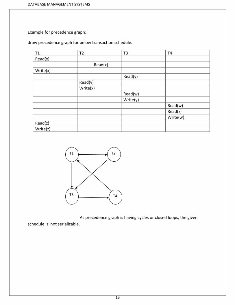
Example for precedence graph:
draw precedence graph for below transaction schedule.
T1 T2 T3 T4
Read(x)
Read(x)
Write(x)
Read(y)
Read(y)
Write(x)
Read(w)
Write(y)
Read(w)
Read(z)
Write(w)
Read(z)
Write(z)
As precedence graph is having cycles or closed loops, the given
schedule is not serializable.
T1 T2
T4
T3
DATABASE MANAGEMENT SYSTEMS
16
Example of conflict serializability:
S2:R1(X), R2(X), R2(Y), W2(Y), R1(Y), W1(X)
Sol:
S21:R2(X), R1(X),R2(Y),W2(Y),R1(Y),W1(Y)
S22:R2(X),R2(Y),R1(X),W2(Y),R1(Y),W1(Y)
S23:R2(X),R2(Y),W2(Y),R1(X),R1(Y),W1(Y)
The schedule S2 derives 3 more schedules (s21,s22,s23) which is called conflict equivalence

DATABASE MANAGEMENT SYSTEMS
17
Concurrency Control:
In case of concurrent instruction executions to preserve atomicity, isolation and
serializability, we use ‘lock-based’ protocol like .
Types of Locks:
1. Binary locks
2. Shared /exclusive locks
Binary Locks − A lock on a data item can be in two states; it is either locked or unlocked. Shared(S)/exclusive(X) − This type of locking mechanism differentiates the locks based
on their uses. If a lock is acquired on a data item to perform a write operation, it is an exclusive lock. Allowing more than one transaction to write on the same data item would lead the database into an inconsistent state. Read locks are shared because no data value is being changed.
Lock Compatibility Matrix –
Lock Compatibility Matrix controls whether multiple transactions can acquire locks on the same resource at the same time.
Shared Exclusive
Shared True False
Exclusive False False
If a resource is already locked by another transaction, then a new lock request can be granted only if the mode of the requested lock is compatible with the mode of the existing lock.
Any number of transactions can hold shared locks on an item, but if any transaction holds an exclusive lock on item, no other transaction may hold any lock on the item.
compatible locks held by other transactions have been released. Then the lock is granted.
DATABASE MANAGEMENT SYSTEMS
18
Lock Granularity :
A database is basically represented as a collection of named data items. The size of the data
item chosen as the unit of protection by a concurrency control program is called GRANULARITY.
Locking can take place at the following level :
Database level. Table level. Page level. Row (Tuple) level. Attributes (fields) level.
i. Database level Locking :
At database level locking, the entire database is locked. Thus, it prevents the use of any tables
in the database by transaction T2 while transaction T1 is being executed. Database level of
locking is suitable for batch processes. Being very slow, it is unsuitable for on-line multi-user
DBMSs.
ii. Table level Locking :
At table level locking, the entire table is locked. Thus, it prevents the access to any row (tuple)
by transaction T2 while transaction T1 is using the table. if a transaction requires access to
several tables, each table may be locked. However, two transactions can access the same
database as long as they access different tables. Table level locking is less restrictive than
database level. Table level locks are not suitable for multi-user DBMS
iii. Page level Locking :
At page level locking, the entire disk-page (or disk-block) is locked. A page has a fixed size such
as 4 K, 8 K, 16 K, 32 K and so on. A table can span several pages, and a page can contain several
rows (tuples) of one or more tables. Page level of locking is most suitable for multi-user
DBMSs.
iv. Row (Tuple) level Locking :
At row level locking, particular row (or tuple) is locked. A lock exists for each row in each table
of the database. The DBMS allows concurrent transactions to access different rows of the same
table, even if the rows are located on the same page. The row level lock is much less restrictive
than database level, table level, or page level locks. The row level locking improves the
availability of data. However, the management of row level locking requires high overhead
cost.
DATABASE MANAGEMENT SYSTEMS
19
v. Attributes (fields) level Locking :
At attribute level locking, particular attribute (or field) is locked. Attribute level locking allows
concurrent transactions to access the same row, as long as they require the use of different
attributes within the row. The attribute level lock yields the most flexible multi-user data
access. It requires a high level of computer overhead.
Locking protocols:
1. Simple lock based protocol
2. Conservative (or) pre-claim locking protocol.
3.2-phase locking protocol
4. Strict 2 phase locking protocol
5. Rigorous 2 phase locking protocol
Simple lock based protocol:
Simplistic lock-based protocols allow transactions to obtain a lock on every object before a
'write' operation is performed. Transactions may unlock the data item after completing the
‘write’ operation.
problems with simple locking are:
1. deadlocks
2. starvation
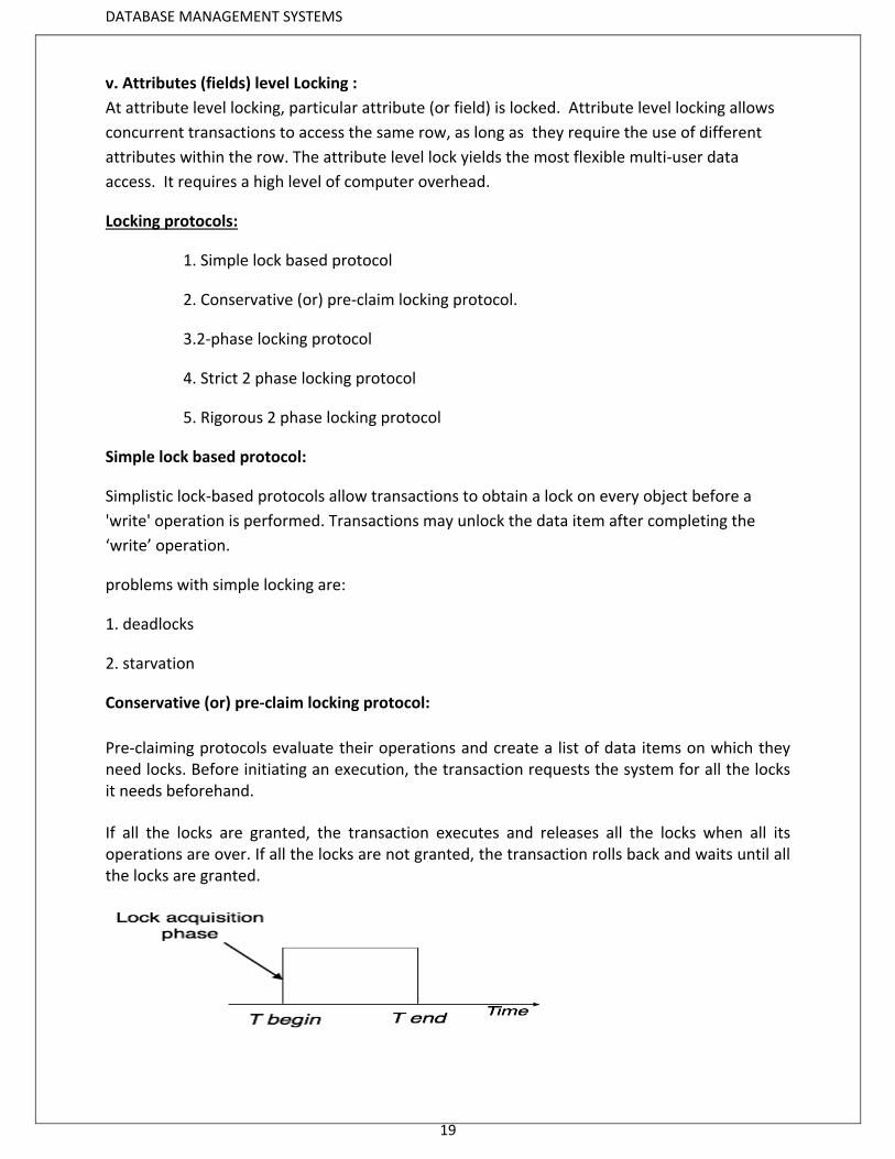
Conservative (or) pre-claim locking protocol:
Pre-claiming protocols evaluate their operations and create a list of data items on which they need locks. Before initiating an execution, the transaction requests the system for all the locks it needs beforehand.
If all the locks are granted, the transaction executes and releases all the locks when all its operations are over. If all the locks are not granted, the transaction rolls back and waits until all the locks are granted.
DATABASE MANAGEMENT SYSTEMS
20
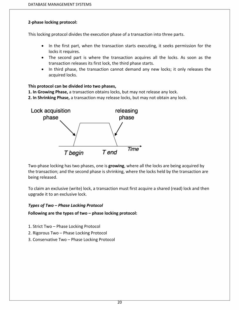
2-phase locking protocol:
This locking protocol divides the execution phase of a transaction into three parts.
In the first part, when the transaction starts executing, it seeks permission for the locks it requires.
The second part is where the transaction acquires all the locks. As soon as the transaction releases its first lock, the third phase starts.
In third phase, the transaction cannot demand any new locks; it only releases the acquired locks.
This protocol can be divided into two phases, 1. In Growing Phase, a transaction obtains locks, but may not release any lock. 2. In Shrinking Phase, a transaction may release locks, but may not obtain any lock.
Two-phase locking has two phases, one is growing, where all the locks are being acquired by the transaction; and the second phase is shrinking, where the locks held by the transaction are being released.
To claim an exclusive (write) lock, a transaction must first acquire a shared (read) lock and then upgrade it to an exclusive lock.
Types of Two – Phase Locking Protocol
Following are the types of two – phase locking protocol:
1. Strict Two – Phase Locking Protocol
2. Rigorous Two – Phase Locking Protocol
3. Conservative Two – Phase Locking Protocol
DATABASE MANAGEMENT SYSTEMS
21
Strict Two-Phase Locking:
1. If a transaction want to read any value it can refers to a shared lock
2. If a transaction to write any particular value it can refers to an exclusive locks
3. A shared lock acquire by multiple transaction at same time.
4. An exclusive lock can be requested by only one transaction at a time on any data
item.
5. Strict Two-Phase Locking Protocol avoids cascaded rollbacks.
6. It ensures that if data is being modified by one transaction, then other transaction
cannot read it until first transaction commits.
phases in strict 2 phase locking:
phase 1: The first phase of Strict-2PL is same as 2PL i.e. when the transaction starts executing, it seeks permission for the locks it requires.
phase 2:After acquiring all the locks in the first phase, the transaction continues to execute normally.
phase 3: But in contrast to 2PL, Strict-2PL does not release a lock after using it. Strict-2PL holds all the locks until the commit point and releases all the locks at a time.
Note: It releases only all exclusive locks but not shared locks after a transaction is committed .
This protocol is not free from deadlocks
Rigorous Two-Phase Locking
Rigorous Two – Phase Locking Protocol avoids cascading rollbacks. This protocol requires that all the share and exclusive locks to be held until the
transaction commits. it releases all the locks including shared and exclusive locks after committing the
transactions. It considers the order of commit among transaction executions.
Conservative Two-Phase Locking Protocol
Conservative Two – Phase Locking Protocol is also called as Static Two – Phase Locking Protocol.
This protocol is almost free from deadlocks as all required items are listed in advanced. It requires locking of all data items to access before the transaction starts.
DATABASE MANAGEMENT SYSTEMS
22
UPGRADING AND DOWNGRADING of Locks:
If a transaction is holding an exclusive lock over an object .It can simply downgrade from
exclusive lock to shared lock after completion of its updation
Similarly a shared lock can be upgraded to exclusive lock on particular data item. when
there is no other transaction is holding exclusive lock on same data item
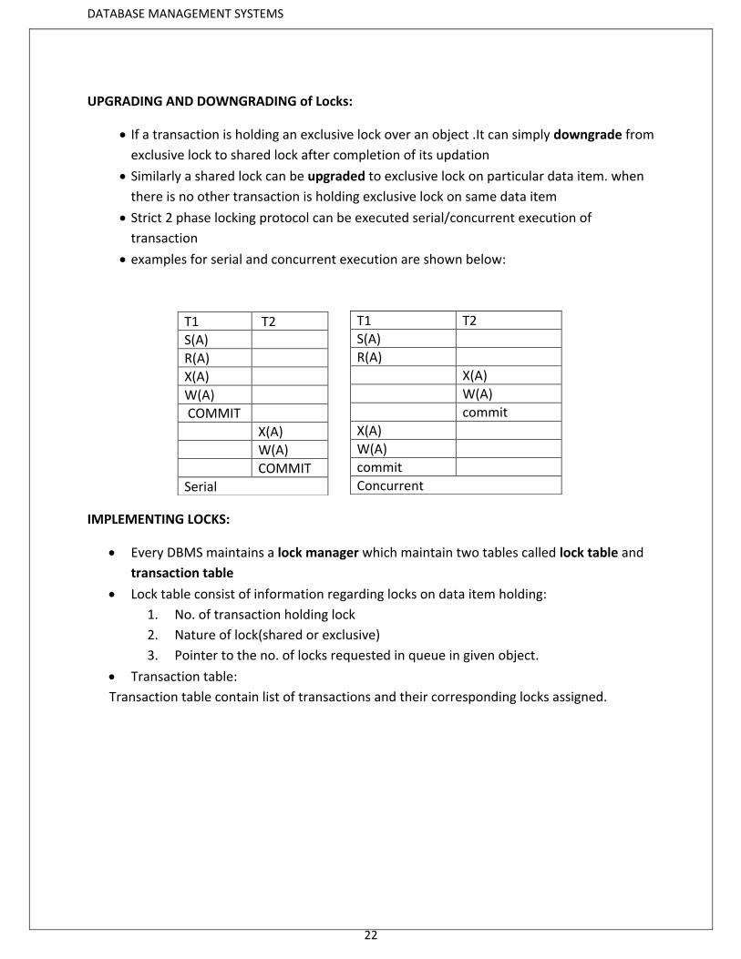
Strict 2 phase locking protocol can be executed serial/concurrent execution of
transaction
examples for serial and concurrent execution are shown below:
IMPLEMENTING LOCKS:
Every DBMS maintains a lock manager which maintain two tables called lock table and
transaction table
Lock table consist of information regarding locks on data item holding:
1. No. of transaction holding lock
2. Nature of lock(shared or exclusive)
3. Pointer to the no. of locks requested in queue in given object.
Transaction table:
Transaction table contain list of transactions and their corresponding locks assigned.
T1 T2
S(A)
R(A)
X(A)
W(A)
COMMIT
X(A)
W(A)
COMMIT
Serial
T1 T2
S(A)
R(A)
X(A)
W(A)
commit
X(A)
W(A)
commit
Concurrent
DATABASE MANAGEMENT SYSTEMS
23
TIME STAMP BASED PROTOCOLS:
The most commonly used concurrency protocol is the timestamp based protocol. This
protocol uses either system time or logical counter as a timestamp.
It starts working as soon as a transaction is created.
Every transaction has a timestamp associated with it, and the ordering is determined by
the age of the transaction.
every data item is given the latest read and write-timestamp.
This lets the system know when the last ‘read and write’ operation was performed on
the data item.
Each transaction is issued a timestamp when it enters into the system. Every read and write operations will be marked with a time stamp of their occurrence. Timestamp Based Protocol helps DBMS to identify the transactions. Time stamp is a unique identifier. Timestamp protocol determines the serializability order. It is most commonly used concurrency protocol. It uses either system time or logical counter as a timestamp.
Timestamp Ordering Protocol
The TO Protocol ensures serializability among transactions in their conflicting read and write operations.
The transaction of timestamp (T) is denoted as TS(T). Data item (X) of read timestamp is denoted by R–timestamp(X). Data item (X) of write timestamp is denoted by W–timestamp(X).
The below assumptions in Time stamp based ordering protocol are based on THOMAS WRITE
RULE.
If a transaction Ti issues a read(X) operation
If TS(Ti)<Write-timestamp(x) , then Operation rejected
If TS(Ti)>=Write-timestamp(x), then Operation executed
All data items time stamps updated
If a transaction Ti issues write(X) operation
If TS(Ti)<Read-Timestamp(x), then operation rejected
If TS(Ti)<Write-timestamp(x), then operation rejected & Ti rolled back
Otherwise operation executed
DATABASE MANAGEMENT SYSTEMS
24
Thomas' Write Rule
This rule states if TS(Ti) < W-timestamp(X), then the operation is rejected and Ti is rolled back.
Time-stamp ordering rules can be modified to make the schedule view serializable.
Instead of making Ti rolled back, the 'write' operation itself is ignored.
Following are the three basic variants of timestamp-based methods of concurrency control:
Total timestamp ordering Partial timestamp ordering Multiversion timestamp ordering
Total timestamp ordering :
The total timestamp ordering algorithm depends on maintaining access to granules in
timestamp order by aborting one of the transactions involved in any conflicting access.
Partial timestamp ordering :
In a partial timestamp ordering, only non-permutable actions are ordered to improve upon the
total timestamp ordering. In this case, both Read and Write granule timestamps are stored.
The algorithm allows the granule to be read by any transaction younger than the last
transaction that updated the granule. A transaction is aborted if it tries to update a granule
that has previously been accessed by a younger transaction.
Multiversion Timestamp ordering :
The multiversion timestamp ordering algorithm stores several versions of an updated granule,
allowing transactions to see a consistent set of versions for all granules it accesses. So, it
reduces the conflicts that result in transaction restarts to those where there is a Write-Write
conflict.

DATABASE MANAGEMENT SYSTEMS
25
VALIDATION BASED PROTOCOLS:
These are also called as optimistic concurrency control method.
An optimistic concurrency control method is also known as validation or certification methods. No checking is done while the transaction is executing. The optimistic method does not require locking or timestamping techniques. Instead, a transaction is executed without restrictions until it is committed. In validation based protocols every transaction is executed on 3 bases
1. read phase
2. validation phase
3. execute or write phase
1. Read phase:
In this phase transaction is executed and all the result will be stored in temporary variables
local to transactions.
2. validation phase:
In this phase the transaction operations are validated without violating the serializability.
3. write phase:
In this phase when a transaction is validated successfully all the values of temporary
variables is updated in the actual data base.
Validation phase:
A transaction is validated based on following time stamp
1. start(ti):
The time at which the transaction ti started it’s execution.
2. validation(ti):
The time at which ti is valid.
3. finish(ti):
The time at which ti finish it’s write operation on the actual data base its execution.
Among two transactions ti&tj, the transactions ti is validated. If it satisfy one of the two
conditions.
If for all ti with ts(ti)<ts(tj)
1. finish(ti)<start(tj)
2. Start(tj)<finish(ti)<validation(tj)

DATABASE MANAGEMENT SYSTEMS
26
The below example shows the interleaved execution of 3 phases of 2 transactions in which
transaction t14 is validated.
Advantages of Optimistic Methods for Concurrency Control :
i. This technique is very efficient when conflicts are rare. The occasional conflicts result in the transaction roll back.
ii. The rollback involves only the local copy of data, the database is not involved and thus there will not be any cascading rollbacks.
Problems of Optimistic Methods for Concurrency Control :
i. Conflicts are expensive to deal with, since the conflicting transaction must be rolled back.
ii. Longer transactions are more likely to have conflicts and may be repeatedly rolled back because of conflicts with short transactions.
T14
T15
Read(B)
Read(B)
B=B-50
Read(A)
A=A+50
Read(A)
Validate
Display(A+B)
Validate
Write(B)
Write(A)
DATABASE MANAGEMENT SYSTEMS
27
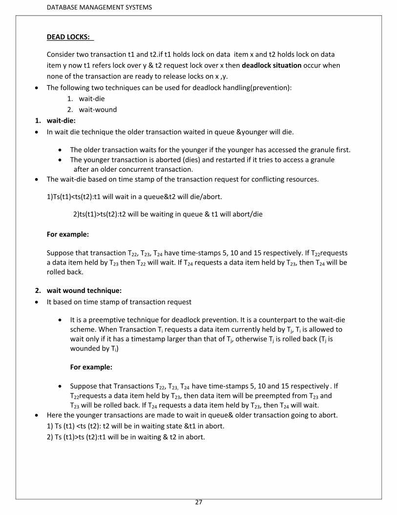
DEAD LOCKS:
Consider two transaction t1 and t2.if t1 holds lock on data item x and t2 holds lock on data
item y now t1 refers lock over y & t2 request lock over x then deadlock situation occur when
none of the transaction are ready to release locks on x ,y.
The following two techniques can be used for deadlock handling(prevention):
1. wait-die
2. wait-wound
1. wait-die:
In wait die technique the older transaction waited in queue &younger will die.
The older transaction waits for the younger if the younger has accessed the granule first.
The younger transaction is aborted (dies) and restarted if it tries to access a granule after an older concurrent transaction.
The wait-die based on time stamp of the transaction request for conflicting resources.
1)Ts(t1)<ts(t2):t1 will wait in a queue&t2 will die/abort.
2)ts(t1)>ts(t2):t2 will be waiting in queue & t1 will abort/die
For example:
Suppose that transaction T22, T23, T24 have time-stamps 5, 10 and 15 respectively. If T22requests a data item held by T23 then T22 will wait. If T24 requests a data item held by T23, then T24 will be rolled back.
2. wait wound technique:
It based on time stamp of transaction request
It is a preemptive technique for deadlock prevention. It is a counterpart to the wait-die scheme. When Transaction Ti requests a data item currently held by Tj, Ti is allowed to wait only if it has a timestamp larger than that of Tj, otherwise Tj is rolled back (Tj is wounded by Ti)
For example:
Suppose that Transactions T22, T23, T24 have time-stamps 5, 10 and 15 respectively . If T22requests a data item held by T23, then data item will be preempted from T23 and T23 will be rolled back. If T24 requests a data item held by T23, then T24 will wait.
Here the younger transactions are made to wait in queue& older transaction going to abort.
1) Ts (t1) <ts (t2): t2 will be in waiting state &t1 in abort.
2) Ts (t1)>ts (t2):t1 will be in waiting & t2 in abort.
DATABASE MANAGEMENT SYSTEMS
28
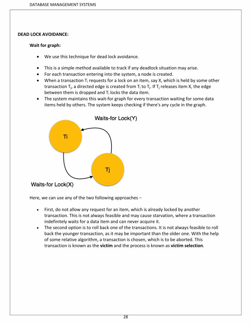
DEAD LOCK AVOIDANCE:
Wait for graph:
We use this technique for dead lock avoidance.
This is a simple method available to track if any deadlock situation may arise.
For each transaction entering into the system, a node is created.
When a transaction Ti requests for a lock on an item, say X, which is held by some other transaction Tj, a directed edge is created from Ti to Tj. If Tj releases item X, the edge between them is dropped and Ti locks the data item.
The system maintains this wait-for graph for every transaction waiting for some data items held by others. The system keeps checking if there's any cycle in the graph.
Here, we can use any of the two following approaches −
First, do not allow any request for an item, which is already locked by another transaction. This is not always feasible and may cause starvation, where a transaction indefinitely waits for a data item and can never acquire it.
The second option is to roll back one of the transactions. It is not always feasible to roll back the younger transaction, as it may be important than the older one. With the help of some relative algorithm, a transaction is chosen, which is to be aborted. This transaction is known as the victim and the process is known as victim selection.
DATABASE MANAGEMENT SYSTEMS
29
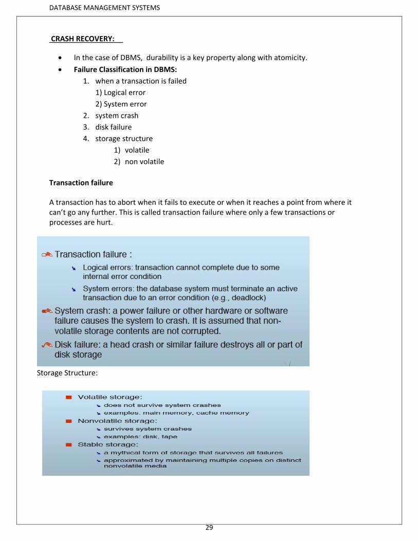
CRASH RECOVERY:
In the case of DBMS, durability is a key property along with atomicity.
Failure Classification in DBMS:
1. when a transaction is failed
1) Logical error
2) System error
2. system crash
3. disk failure
4. storage structure
1) volatile
2) non volatile
Transaction failure
A transaction has to abort when it fails to execute or when it reaches a point from where it can’t go any further. This is called transaction failure where only a few transactions or processes are hurt.
Storage Structure:
DATABASE MANAGEMENT SYSTEMS
30
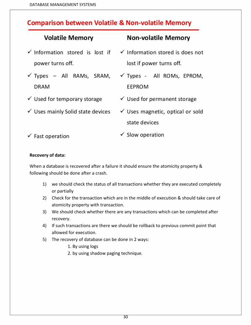
Recovery of data:
When a database is recovered after a failure it should ensure the atomicity property &
following should be done after a crash.
1) we should check the status of all transactions whether they are executed completely
or partially
2) Check for the transaction which are in the middle of execution & should take care of
atomicity property with transaction.
3) We should check whether there are any transactions which can be completed after
recovery.
4) If such transactions are there we should be rollback to previous commit point that
allowed for execution.
5) The recovery of database can be done in 2 ways:
1. By using logs
2. by using shadow paging technique.
DATABASE MANAGEMENT SYSTEMS
31
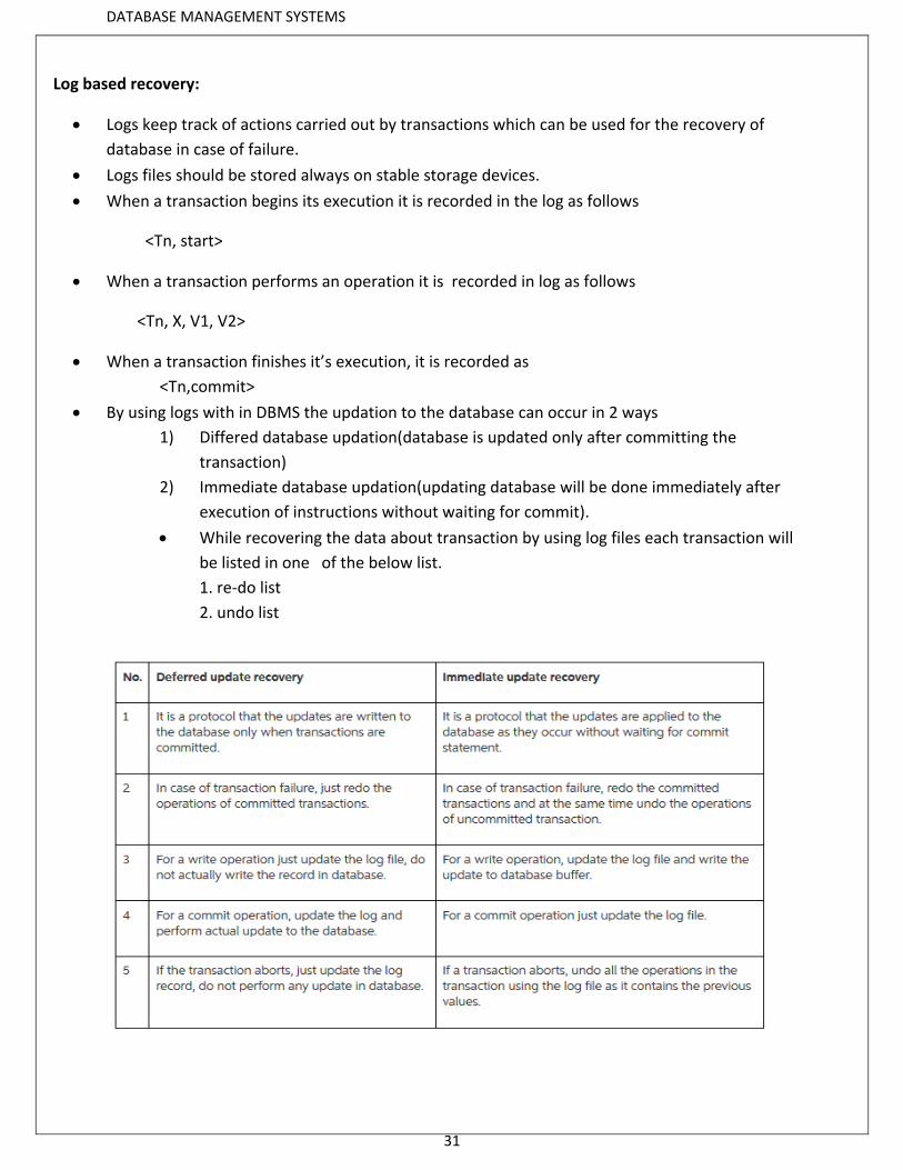
Log based recovery:
Logs keep track of actions carried out by transactions which can be used for the recovery of
database in case of failure.
Logs files should be stored always on stable storage devices.
When a transaction begins its execution it is recorded in the log as follows
<Tn, start>
When a transaction performs an operation it is recorded in log as follows
<Tn, X, V1, V2>
When a transaction finishes it’s execution, it is recorded as
<Tn,commit>
By using logs with in DBMS the updation to the database can occur in 2 ways
1) Differed database updation(database is updated only after committing the
transaction)
2) Immediate database updation(updating database will be done immediately after
execution of instructions without waiting for commit).
While recovering the data about transaction by using log files each transaction will
be listed in one of the below list.
1. re-do list
2. undo list
DATABASE MANAGEMENT SYSTEMS
32
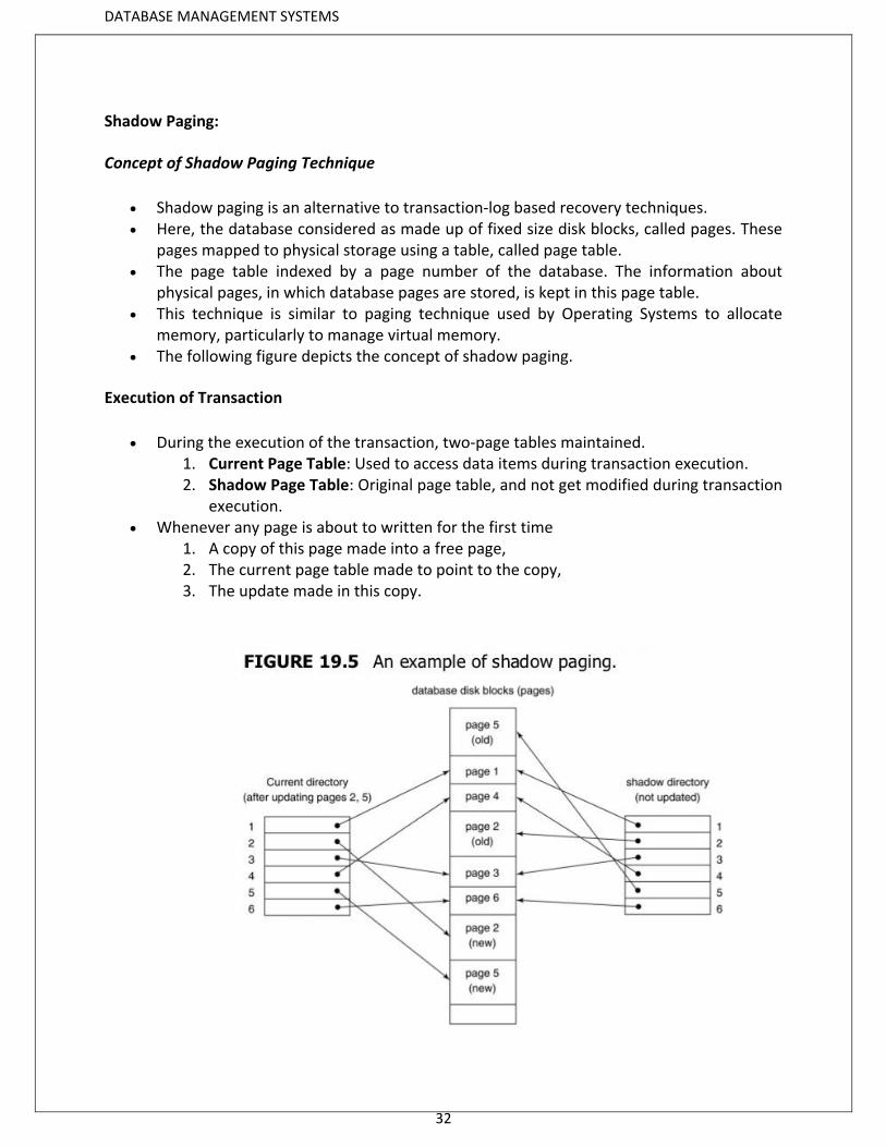
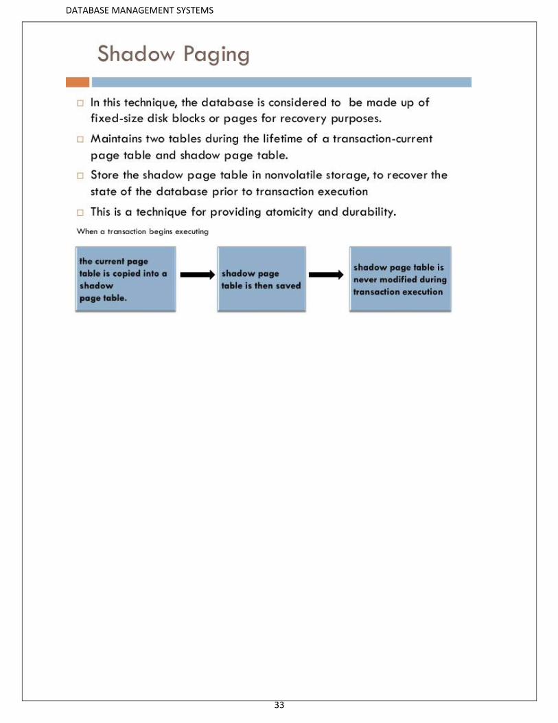
Shadow Paging:
Concept of Shadow Paging Technique
Shadow paging is an alternative to transaction-log based recovery techniques. Here, the database considered as made up of fixed size disk blocks, called pages. These
pages mapped to physical storage using a table, called page table. The page table indexed by a page number of the database. The information about
physical pages, in which database pages are stored, is kept in this page table. This technique is similar to paging technique used by Operating Systems to allocate
memory, particularly to manage virtual memory. The following figure depicts the concept of shadow paging.
Execution of Transaction
During the execution of the transaction, two-page tables maintained. 1. Current Page Table: Used to access data items during transaction execution. 2. Shadow Page Table: Original page table, and not get modified during transaction
execution. Whenever any page is about to written for the first time
1. A copy of this page made into a free page, 2. The current page table made to point to the copy, 3. The update made in this copy.
DATABASE MANAGEMENT SYSTEMS
33
DATABASE MANAGEMENT SYSTEMS
34
Recovering data of concurrent transactions:
While recovering concurrent transaction it is difficult to recover by using lock files so along with
lock files check points are considered for the recovery of concurrent transaction.
Check point:
It is a point at a time where all transaction are committed & the database in consistence state.
While recovering start from the end transaction till it reaches any check point.
During this process categorized each transaction into UNDO/REDO list.
All the transactions in UNDO list should not be saved.
All the transaction in Redo list should saved and rollback then.
<Tn,start>undo list
<Tn, start>
: Redo list
<Tn, commit>
Granularity:
It refers to the size of the database item which can be locked.
Multiple Granularity locking:
It refers to dividing the database into a hierarchy of data items on which locks can be applied as
a whole or individual data item.
We can divide database hierarchy files into pages and each page consists of record.

DATABASE MANAGEMENT SYSTEMS
35
ARIES Recovery Algorithm:
• A steal, no-force approach
• Steal: if a frame is dirty and chosen for replacement, the page it contains is
written to disk even if the modifying transaction is still active.
• No-force: Pages in the buffer pool that are modified by a transaction are not
forced to disk when the transaction commits.
Algorithms for Recovery and Isolation Exploiting Semantics, or ARIES is a recovery algorithm
designed to work with a no-force, steal database approach.
The ARIES recovery procedure consists of three main steps:
1. Analysis
The analysis step identifies the dirty (updated) pages in the buffer, and the set of transactions active at the time of the crash. The appropriate point in the log where the REDO operation should start is also determined
2. REDO
The REDO phase actually reapplies updates from the log to the database. Generally, the REDO operation is applied to only committed transactions. However, in ARIES, this is not the case. Certain information in the ARIES log will provide the start point for REDO, from which REDO operations are applied until the end of the log is reached. In addition, information stored by ARIES and in the data pages will allow ARIES to determine whether the operation to be redone has actually been applied to the database and hence need not be reapplied. Thus only the necessary REDO operations are applied during recovery.
3. UNDO
During the UNDO phase, the log is scanned backwards and the operations of transactions that were active at the time of the crash are undone in reverse order. The information needed for ARIES to accomplish its recovery procedure includes the log, the Transaction Table, and the Dirty Page Table. In addition, check pointing is used. These two tables are maintained by the transaction manager and written to the log during check pointing.
DATABASE MANAGEMENT SYSTEMS
36
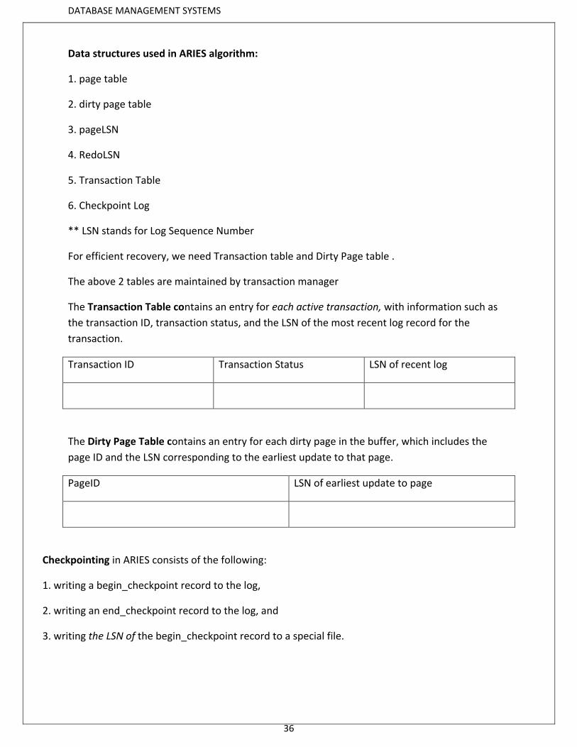
Data structures used in ARIES algorithm:
1. page table
2. dirty page table
3. pageLSN
4. RedoLSN
5. Transaction Table
6. Checkpoint Log
** LSN stands for Log Sequence Number
For efficient recovery, we need Transaction table and Dirty Page table .
The above 2 tables are maintained by transaction manager
The Transaction Table contains an entry for each active transaction, with information such as
the transaction ID, transaction status, and the LSN of the most recent log record for the
transaction.
Transaction ID Transaction Status LSN of recent log
The Dirty Page Table contains an entry for each dirty page in the buffer, which includes the
page ID and the LSN corresponding to the earliest update to that page.
PageID LSN of earliest update to page
Checkpointing in ARIES consists of the following:
1. writing a begin_checkpoint record to the log,
2. writing an end_checkpoint record to the log, and
3. writing the LSN of the begin_checkpoint record to a special file.

DATABASE MANAGEMENT SYSTEMS
37
This Checkpoint log file is accessed during recovery to locate the last checkpoint information.
After a crash, the ARIES recovery manager takes over.
Information from the last checkpoint is first accessed through the special file. The analysis
phase starts at the begin_checkpoint record and proceeds to the end of the log. When the
end_checkpoint record is encountered, the Transaction Table and Dirty Page Table are accessed
(recall that these tables were written in the log during checkpointing). During analysis, the log
records being analyzed may cause modifications to these two tables. For instance, if an end log
record was encountered for a transaction T in the Transaction Table, then the entry for T is
deleted from that table. If some other type of log record is encountered for a transaction T ,
then an entry for T is inserted into the Transaction Table, if not already present, and the last
LSN field is modified. If the log record corresponds to a change for page P, then an entry would
be made for page P (if not present in the table) and the associated LSN field would be modified.
When the analysis phase is complete, the necessary information for REDO and UNDO has been
compiled in the tables.
The REDO phase follows next.
ARIES starts redoing at a point in the log where it knows (for sure) that previous changes to
dirty pages have already been applied to the database on disk. It can determine this by finding
the smallest LSN, M, of all the dirty pages in the Dirty Page Table, which indicates the log
position where ARIES needs to start the REDO phase. Any changes corresponding to an LSN <
M, for redoable transactions, must have already been propagated to disk or already been
overwritten in the buffer; otherwise, those dirty pages with that LSN would be in the buffer
(and the Dirty Page Table). So, REDO starts at the log record with LSN = M and scans forward to
the end of the log. For each change recorded in the log, the REDO algorithm would verify
whether or not the change has to be reapplied. For example, if a change recorded in the log
pertains to page P that is not in the Dirty Page Table, then this change is already on disk and
does not need to be reapplied. Or, if a change recorded in the log (with LSN = N, say) pertains to
page P and the Dirty Page Table contains an entry for P with LSN greater than N, then the
change is already present. If neither of these two conditions hold, page P is read from disk and
DATABASE MANAGEMENT SYSTEMS
38
the LSN stored on that page, LSN(P), is compared with N. If N < LSN(P), then the change has
been applied and the page does not need to be rewritten to disk.
Once the REDO phase is finished, the database is in the exact state that it was in when the
crash occurred. The set of active transactions—called the undo_set—has been identified in the
Transaction Table during the analysis phase.
Now, the UNDO phase proceeds by scanning backward from the end of the log and undoing the
appropriate actions. A compensating log record is written for each action that is undone. The
UNDO reads backward in the log until every action of the set of trans-actions in the undo_set
has been undone. When this is completed, the recovery process is finished and normal
processing can begin again.
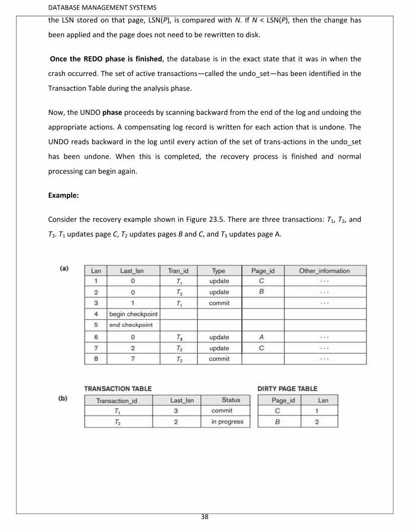
Example:
Consider the recovery example shown in Figure 23.5. There are three transactions: T1, T2, and
T3. T1 updates page C, T2 updates pages B and C, and T3 updates page A.
DATABASE MANAGEMENT SYSTEMS
39
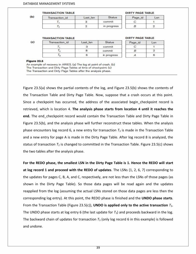
Figure 23.5(a) shows the partial contents of the log, and Figure 23.5(b) shows the contents of
the Transaction Table and Dirty Page Table. Now, suppose that a crash occurs at this point.
Since a checkpoint has occurred, the address of the associated begin_checkpoint record is
retrieved, which is location 4. The analysis phase starts from location 4 until it reaches the
end. The end_checkpoint record would contain the Transaction Table and Dirty Page Table in
Figure 23.5(b), and the analysis phase will further reconstruct these tables. When the analysis
phase encounters log record 6, a new entry for transaction T3 is made in the Transaction Table
and a new entry for page A is made in the Dirty Page Table. After log record 8 is analyzed, the
status of transaction T2 is changed to committed in the Transaction Table. Figure 23.5(c) shows
the two tables after the analysis phase.
For the REDO phase, the smallest LSN in the Dirty Page Table is 1. Hence the REDO will start
at log record 1 and proceed with the REDO of updates. The LSNs {1, 2, 6, 7} corresponding to
the updates for pages C, B, A, and C, respectively, are not less than the LSNs of those pages (as
shown in the Dirty Page Table). So those data pages will be read again and the updates
reapplied from the log (assuming the actual LSNs stored on those data pages are less then the
corresponding log entry). At this point, the REDO phase is finished and the UNDO phase starts.
From the Transaction Table (Figure 23.5(c)), UNDO is applied only to the active transaction T3.
The UNDO phase starts at log entry 6 (the last update for T3) and proceeds backward in the log.
The backward chain of updates for transaction T3 (only log record 6 in this example) is followed
and undone.