unit 6 – uhf 625w amplifier integrated circuit lm 78 l12 acz ic3 60141 1 varistor s14k60 vr1 71037...
TRANSCRIPT

Unit 6 – UHF 625W Amplifier
- 1 -

Unit 6 – UHF 625W Amplifier
- 2 -
1. 625W amplifier: 1.1. Introduction: This module amplifies the RF power that comes from the 3dB hibrid splitter to the 625W level. 1.2. +32Vdc 25 A switched power supply: Its function is to supply the 160W amplifier and also the protection circuits that compose the module. The input voltage is about 50Vdc, obtained from a 36Vac three-phase rectifyng supply.
1.3. Protections and Monitoring: For these functions, we have: VSWR Circuit: it protects the amplifier module transistors, when the output VWSR is superior to 4%. This circuit acts in the output transistors bias gate. Temperature Circuit: it acts in the output transistors bias gate when the heat sink temperature is above 56°C. Forward RF power limiting circuit: it acts in the output transistor bias gates when the RF output power exceeds the pre-fixed value, this way limiting the maximum power. 1.4. Supply fuses: In this circuit there are four 15 A fuses, one for each 160W amplifiers. 1.5. Amplifier stages: Four amplifier modules with 160W each are used in parallel. Each 160W amplifier module has four LDMOS transistors MRF373A in parallel. Its gain is about 20 dB in class AB.
Unit 6 – UHF 625W Amplifier
- 3 -
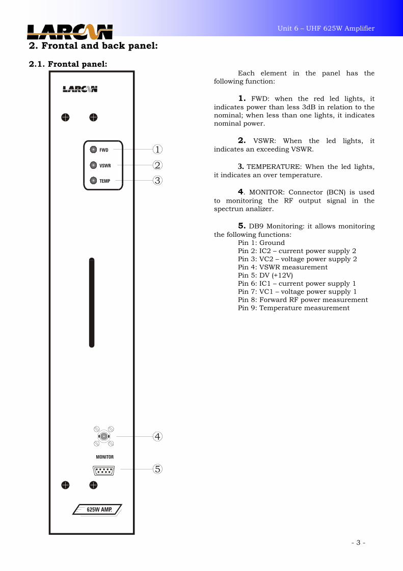
2. Frontal and back panel: 2.1. Frontal panel:
Each element in the panel has the
following function:
1. FWD: when the red led lights, it indicates power than less 3dB in relation to the nominal; when less than one lights, it indicates nominal power.
2. VSWR: When the led lights, it
indicates an exceeding VSWR. 3. TEMPERATURE: When the led lights,
it indicates an over temperature.
4. MONITOR: Connector (BCN) is used to monitoring the RF output signal in the spectrun analizer.
5. DB9 Monitoring: it allows monitoring the following functions:
Pin 1: Ground Pin 2: IC2 – current power supply 2 Pin 3: VC2 – voltage power supply 2 Pin 4: VSWR measurement Pin 5: DV (+12V) Pin 6: IC1 – current power supply 1 Pin 7: VC1 – voltage power supply 1 Pin 8: Forward RF power measurement Pin 9: Temperature measurement
Unit 6 – UHF 625W Amplifier
- 4 -
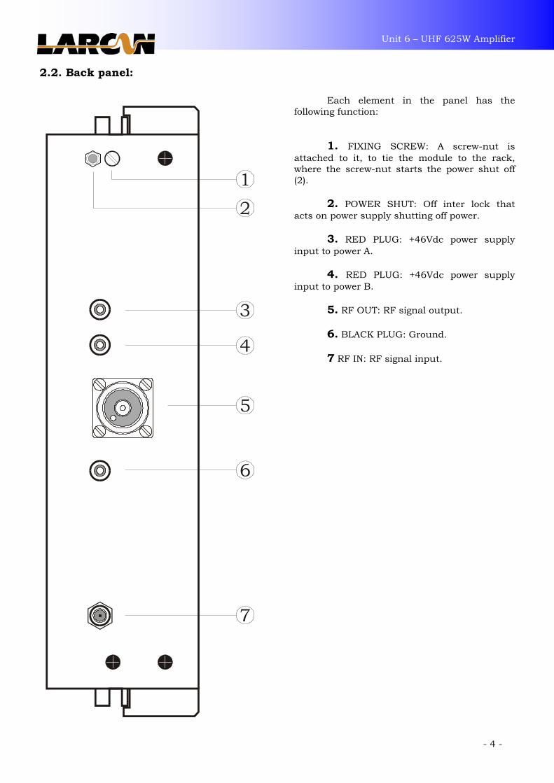
2.2. Back panel:
Each element in the panel has the following function:
1. FIXING SCREW: A screw-nut is attached to it, to tie the module to the rack, where the screw-nut starts the power shut off (2). 2. POWER SHUT: Off inter lock that acts on power supply shutting off power.
3. RED PLUG: +46Vdc power supply input to power A.
4. RED PLUG: +46Vdc power supply input to power B. 5. RF OUT: RF signal output.
6. BLACK PLUG: Ground.
7 RF IN: RF signal input.

Unit 6 – UHF 625W Amplifier
- 5 -
3. +32V 25A switched power supply: 3.1. Function:
There are two +32V 25 A switched power supplies, each one supply two 160W amplifier modules. 3.2. Technical Characteristics: Input voltage: _____________________________________________________________________ +46Vdc with 18 A Output voltage: _____________________________________________________________________ +32Vdc to 25 A Module Current: _____________________________________________ 11.5 A with black video + Audio Carrier 3.3. Technical description: The integrated circuit IC1 operates as PWM (Pulse Width modulator). In the IC1 pins 11 and 12 , we have the IC supply voltage that comes from zener D1. The power supply Soft Start is performed by capacitor C9 1µF with resistor R9 10K, acting in IC1 pin 4. The power supply oscillation is determined by capacitor C14 and by resistor R12. In pin 9 and 10 from integrated circuit TL494 we have pulses that will activate the current drivers Q1 and Q2. This pulses are transferred to transformer T1 that will activate, through its secondary, the FET’s Q3 and Q4. D7 is a fast diode used in switching to avoid reverse voltages in the FET’s. T2 function is to isolate switched power supply from the continuing voltage and also, with capacitors C24, C25, C26 and C27 form the filter LC. S1 is a current sample sensor. R25 adjusts the current to be measured in connector CN1:4.
The over current protection is performed by R26, acting in IC2B pin 6. The voltage at IC2B pin 7, feeds the IC1 control pin 4, reducing the output voltage.
The voltage divider formed by R14 and R15//R16 determines the power supply output voltage. This voltage sample acts in pin 1 from integrated circuit TL494. Any voltage variation in the output is compensated in pin 1 that acts in the pulse width present on pins 9 and 10. The resistors R6 and R7 and capacitor C10 act in the power supply voltage feed back. The capacitors C1 to C3 and C4 to C6 form an input filter CA after the rectification, and C1 to C3 form the output filter.

Unit 6 – UHF 625W Amplifier
Unit 6 – UHF 625W Amplifier
- 6 - - 6 -
3.4. Circuit Diagram FTE022:

Unit 6 – UHF 625W Amplifier
- 7 -
3.5. Layout FTE022:

Unit 6 – UHF 625W Amplifier
- 8 -
3.6. Parts list FTE022:
Quant. Description Position Code 1 INTEGRATED CIRCUIT LM 358 IC2 60052
1 INTEGRATED CIRCUIT TL 494 CN IC1 60074
1 INTEGRATED CIRCUIT LM 78 L12 ACZ IC3 60141
1 VARISTOR S14K60 VR1 71037
1 CAPAC. ELCO RADIAL 100µF 63V C8 74018
1 CAPAC. ELCO RADIAL 10µF 63V C20 74023
5 CAPAC. ELCO RADIAL 2200µF 63V C4,C5,C6,C24,C26 74025
3 CAPAC. ELCO RADIAL 220µF 63V HFC C1,C2,C3 74037
1 CAPAC. ELCO RADIAL 47µF 63V C18 74045
1 CAPAC. POLIESTER METAL. 470ηF C22 75015
5 CAPAC. POLIESTER METAL. 100ηF C10,C19,C21,C23,C28 75019
1 CAPAC. POLIESTER METAL. 1µF C9 75021
6 CAPAC. POLIESTER METAL. 2,2 µF C7,C11,C12,C15,C25,C27 79512
1 CAPAC. MUTLILAYER 1ηF C14 76044
1 CAPAC. MUTLILAYER 10ηF C16 76046
2 CAPAC. PLATE 2 K 2 C13,C17 79512
4 DIODE 1N 4148 D2,D3,D5,D6 82011
1 DIODE 1N 4743 A 13V D4 82021
1 DIODE 1N 5352 15V D1 82074
1 TRIMPOT 10 K R26 90027
1 TRIMPOT 1 K R25 90028
1 SHOCK T1 95076
1 RESISTOR 1/8W 15 Ohms R10 100009
1 RESISTOR 1/8W 180 Ohms R11 100020
7 RESISTOR 1/8W 1 K R8,R13,R17,R20,R21,R27,R28 100028
1 RESISTOR 1/8W 4 K 7 R5 100037
5 RESISTOR 1/8W 10 K R9,R16,R18,R19,R22 100041
2 RESISTOR 1/8W 18 K R4,R23 100044
1 RESISTOR 1/8W 33 K R7 100047
3 RESISTOR 1/8W 47 K R12,R15,R14 100048
1 RESISTOR 1/8W 220 K R6 100056
1 RESISTOR 1/8W 470 K R24 100058
3 RESISTOR AXIAL WIRE 5W 1 K R1,R2,R3 105016
1 TRANSISTOR BC 639 Q1 120007
1 TRANSISTOR BC 640 Q2 120008
1 CONNECTOR BURDY MMP-5S1 COM1 800818
1 CURRENT SENSOR S1 IMPSEN001
1 PCB +32V 25 A SWITCHED POWER S PCI1 PCIFTE022

Unit 6 – UHF 625W Amplifier
- 9 -

Unit 6 – UHF 625W Amplifier
- 10 -
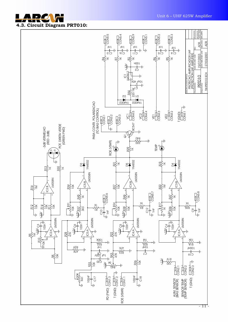
4. Amplifier protection: 4.1. Function: This module function is to protect the final amplifier modules against excessive VSWR, temperature and excessive RF power. 4.2. Technical Description: Directional Coupling detectors in the amplifier module output gives information about the Forward RF Power and VSWR. The voltage proportional to the Forward RF Power supplies IC5A buffer amplifier integrated circuit. This amplifier output supplies two comparing circuits, IC5B and IC2A. The integrated circuit IC5B acts as a power limiting be that, if the forward RF power exceeds the pre-fixed value by trimpot R31, transistor Q1 is conducted by diode D3 and resistor R39, removing the bias from the final amplifier gates. The integrated circuit IC2A compares the forward RF power to a –3dB adjusted value by R10, lightning the forward green Led in the panel. The integrated circuit IC2B is an inverter amplifier, be that, when the forward RF power drops below to –3dB, its output reaches +12V lightning the forward red Led in the panel. VSWR proportional voltage supplies IC4A buffer amplifier integrated circuit. IC4A output supplies IC4B comparing input, and also the monitoring in the panel by resistor R1. If the RF signal exceeds the pre-fixed value by R24, the VSWR Led lights in the panel and transistor Q1 conducts through diode D5 and resistor R39, removing the bias from the output amplifier transistor gates. A temperature sensor protects the temperature. It provides a proportional voltage to the 10mV/°C monitored temperature, be that, for 50°C we have 500mV. Through IC3A buffer amplifier, this voltage is compared to a pre-determined value by trimpot R17 and also sent to the frontal panel. IC3B integrated circuit lights “temperature” Led in the panel and by transistor Q1, diode D4 and resistor R39, is removed the bias from the final amplifier transistors. Diodes D1 and D2 and the fixed voltage regulator IC1, are responsible for generating the +12V voltage that supplies several IC’s from the protection circuit.
Unit 6 – UHF 625W Amplifier
4.3. Circuit Diagram PRT010:
- 11 -

Unit 6 – UHF 625W Amplifier
- 12 -
4.4. Layout PRT010:

Unit 6 – UHF 625W Amplifier
- 13 -
4.5. Parts list PRT010:
Quant. Description Position Code 4 INTEGRATE CIRCUIT LM 358 IC2,IC3,IC4,IC5 60052
1 CAPAC. ELCO RADIAL 10µF 50V C1 74024
5 CAPAC. POLYESTER METAL. 100ηF C2,C3,C4,C5,C6 75016
8 CAPAC. MULTILAYER. 1ηF C7,C8,C9,C10,C11,C12,C13,C14, 76044
C19,C16
5 DIODE 1N 4002 D1,D2,D3,D4,D5 82001
2 DIODE LED 3 mm (RED) DL1 82017
1 DIODE LED 3 mm (THREE COLOR) DL2 82093
3 TRIMPOT 10 K R10,R24,R31 90027
1 TRIMPOT 1 K R17 90028
1 RESISTOR 1/8W 100 Ohms R19 100017
1 RESISTOR 1/8W 220 Ohms R40 100021
13 RESISTOR 1/8W 1 K R1,R2,R3,R4,R5,R6,R7,R13,R16, 100028
R21,R30,R35,R39
1 RESISTOR 1/8W 3 K 3 R37 100035
11 RESISTOR 1/8W 10 K R8,R11,R12,R14,R18,R26,R27, 100041
R33,R34,R36,R38
4 RESISTOR 1/8W 47 K R22,R23,R28,R29 100048
1 RESISTOR 1/8W 100 K R32 100051
4 RESISTOR 1/8W 1 M R9,R16,R20,R25 100059
1 TRANSISTOR BC 547 A Q1 120003
1 FIXED VOLTAGE REGULATOR 7812 IC1 126019
1 MALE CONECTOR MULTIP. 3 PINS COM1,COM2,COM3 800817
1 CONNECTOR BURDY COM4 800818
1 MALE CON. FLAT-CABLE ANG. 10 P. COM5 801814
1 PCB 250W UHF PROTECTION PCI1 PCIPRT010

Unit 6 – UHF 625W Amplifier
- 14 -
5. Supply fuses: 5.1. Function: This circuit protects the both power supplies against short circuit zener diodes D1 to D4, perform the over voltage protection. 5.2. Technical Description: The +32Vdc voltage of each internal power supplies the power amplifier modules by 4 fuses of 15 A each, F1 and F2 for power supply A and F3 and F4 for power supply B.
5.3. Circuit diagram SDA001:

Unit 6 – UHF 625W Amplifier
- 15 -
5.4. Layout SDA001: 5.5. Parts list SDA001:
Quant. Description Position Code 5 DIODE ZENER 1N 5365 82116
1 FUSE 5 AMP 86005
4 FUSE 15 AMP 86041
1 PCB 625W UHF AMPLIFIER OUTPUT PCI1 PCISDA001

Unit 6 – UHF 625W Amplifier
- 16 -
6. 625W final amplifier: 6.1. Function: Its function is to amplify the power that comes from splitter 1:8 to a 160W output level. 6.2. Technical characteristics: Output power: _____________________________________________________________________ 160W Peak Sync Gain: ________________________________________________________________________________________ 20 dB Activating temperature: ________________________________________________________________________ 56°C 6.3. Technical Description:
The UHF 160W amplifier is formed by the combination of two 80W amplifiers. At the input and output there are two 3 dB hibrid couplers with the rejection loads R1 and R14. The signal splitted by the 3 dB coupler input feeds the two 80W amplifiers through C1 and C2. At the input of each 50W amplifier there is a balun L1 and L2 that splittes the signal again for
two transistor Q1, Q2 and Q3, Q4 respectively. The amplified signals through the baluns L5 and L6 are combined in the final 3 dB coupler with
the coupling capacitors C28 and C34. The bias circuit is formed by resistores R12, R13 and zener diode D3 that generates a +15Vdc. Through trimpot’s R6 and R7 the bias voltage for the transistor’s gate are adjusted. The diode D1 and D2 allow a protection, for the amplifier, reducing the bias voltage and the gain
of the amplifier.

Unit 6 – UHF 625W Amplifier
Unit 6 – UHF 625W Amplifier
- 17 - - 17 -
6.4. Circuit Diagram APU006:

Unit 6 – UHF 625W Amplifier
- 18 -
Unit 6 – UHF 625W Amplifier
- 18 -
6.5. Layout APU006:
Unit 6 – UHF 625W Amplifier
- 19 -
6.6. Parts list APU006:
Quant. Description Position Code 1 CAPAC. ELCO. RADIAL 220µF 63V HFC C31 74037
1 DIODES 1N 4733 A 5V1 D3 82018
1 DIODES 1N 4735 A 6V2 D4 82022
4 CAPAC. MONOL. 27ρF C11,C12,C13,C14 IMPC00088
6 CAPAC. MONOL. 10ρF C15,C17,C21,C24,C25,C26 IMPC00092
2 CAPAC. MONOL. 5ρ6 C19,C20 IMPC00093
2 CAPAC. MONOL. 22ρF C16,C18 IMPC00091
4 CAPAC. MONOL. 56ρF C1,C2,C28,C34 IMPC00101
30 Cm CABLE COAXIAL UT 90-25 L1,L2,L5,L6 IMPCX0008
2 RESISTOR RF CBT-20-5 50 Ohms R1,R14 IMPR00011
4 TRANSISTOR LDMOS MRF 373 A Q1,Q2,Q3,Q4 IMPT00131
8 CAPACITOR SMD 1206 10ηF C3,C4,C7,C8,C27,C29,C33,C35 ISMCAP103
8 CAPACITOR SMD 1206 100ηF C5,C6,C9,C10 ISMCAP104
2 DIODE SMD BAS16 D1,D2 ISMDIOS16
10 RESISTOR SMD 1206 1K R2,R3,R4,R5,R8,R9,R10,R11, ISMRES102
R12,R13
2 TRIMPOT SMD 1K R6,R7 ISMTRP102
1 PCB 160W UHF AMPLIFIER LDMOS PCI1 PCIAPU006

Unit 6 – UHF 625W Amplifier
7. 625W UHF amplifier:
- 20 -