unit dimensions (in mm) 7 specifications (please inquire ... filtri doppi/16 fd/re51410...2/10 bosch...
TRANSCRIPT

1/10Duplex Filter
Types 16 FD 2500 to 7500
Nominal size according to DIN 24550: 2500 to 7500 Nominal pressure 16 bar Connections up to DN 250 Operating temperature …°C to …
RE 51410/08.08
Table of contents Application
– Filtration of hydraulic fluids and lubricants.– Filtration of liquids and gases.– Direct inline installation. – Direct wear protection for downstream components and
systems.– Continuous operation through duplex filter type construction.
Contents PageApplication, symbol 1Construction, filter element, accessories, characteristic lines and quality and standardization 2Order details 3Order details: electric switching element for contamination indicator, Plug-in connectors according to IEC 60947-5-2 4Symbols for electric switching element for contamination indicator 5Specifications 6Unit dimensions 7Spare parts 8 and 9Installation, starting and maintenance 10
Symbol
Application 1Symbol 1Construction 2Filter element 2Accessories 2Characteristic lines 2Quality and standardization 2Order details 3Order details: electric switching element for contamination indicator 4Plug-in connectors according to IEC 60947-5-2 (dimensions in mm [inch]) 4Symbols 5Specifications (Please inquire in case the intended use of unit is outside the given values!) 6Unit dimensions (in mm) 7Spare parts 8Spare parts (insert for DIN and SAE filters) 9Installation, starting and maintenance 10

2/10 Bosch Rexroth AG Hydraulics 16 FD 2500 - 7500 RE 51410/08.08
ConstructionWelded steel construction with two filter housing connected with each other as one switching unit via four throttle valve. The connections are on top of each other. Filter cover with vent screw, filter fitted with drain plug. Material: as per spare parts list.
Filter element
Pleated design with optimized pleat density and with various filter media.The filter element is the most important component of the “FILTER” system in view of prolonged life and wear protection of the sytem.Oil cleanliness, the initial pressure drop and the dirt holding capacity are the most important criteria for selection.
For further detailed information please refer to our ”Filter Elements” brochure.
Accessories
Maintenance indicatorFor monitoring the filter element’s contamination status, visual and visual/electrical indicators, available with one or two switching points.
Bypass valve To protect the filter element during startup and overpressur- ization due to clogging.
Vent valve For removing the air from the filter during starting and for safe depressurization.
Quality and standardization
The development, manufacture and assembly of BRFS- industrial filters and BRFS filter elements is carried out within the framework of a certified quality management system in accordance with DIN EN ISO 9001:2000.Certification of the filters by accredited institutions (for exam-ple TÜV, GL, LRS, LRIS, ABS, BV, DNV, DRIRE, UDT, etc.) is available on request.
The stability calculation and testing of the filters take place according to updated rules, as well as in accordance with national and international standards.The CE-identification mark according to the Pressure Equip-ment Directive 97/23/Ec depends upon the individual appli-cation and operating conditions.We are able to perform the conformity evaluation in accor-dance with the Pressure Equipment Directive if requested.
Characteristic lines
A proper filter selection is enabled by our “BRFS-FILTERSELECT“ software.
The characteristic lines for the filters in this brochure are available in the filter calculation program by Bosch Rexroth Filtration Systems (BRFS) under: http://www.eppensteiner.de/deutsch/download/Auslegungs-programm2005/filterselect_frz.htm
Hydraulics Bosch Rexroth AGRE 51410/08.08 16 FD 2500 - 7500 3/10
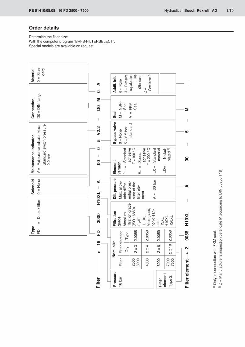
Order detailsDetermine the filter size: With the computer program “BRFS-FILTERSELECT”. Special models are available on request.
1) O
nly
in c
onne
ctio
n wi
th F
KM s
eal.
2) Z
= M
anuf
actu
rer's
insp
ectio
n ce
rtific
ate
M a
ccor
ding
to D
IN 5
5350
T18M
aint
enan
ce in
dica
tor
V =
Maint
enan
ce in
dicato
r, vis
ual
Stan
dard
swi
tch
pres
sure
2.
2 ba
r
Type
FD
= Du
plex
filte
rCo
nnec
tion
D0 =
DIN
flan
geM
ater
ial
0 =
Stan
-
dard
Sole
noid
0 =
None
Filte
r16
FD
3000
H10
XL –
A 00
–
0 5
V2.2
–
D0
M
0 A
Filte
r ele
men
t 2
. 00
58
H10X
L –
A 00
–
5 –
M
Filte
r el
emen
tTy
pe 2
.
Filtr
atio
n gr
ade
Abso
lute
filt
ratio
n gr
ade
(ISO
168
89)
in µ
m
H…XL
=
Micr
ogla
ss,
non-
clean
-ab
le,
H3XL
H1
0XL
H20X
L
Diff.
pre
ssur
eM
ax. a
llow-
able
diff
er-
entia
l pre
s-su
re o
f the
filt
er e
le-
men
t
A =
30 b
ar
Pres
sure
16 b
arEl
emen
t ve
rsio
n0…
=
Stan
dard
ad
hesiv
e
T
= 10
0 °C
E… =
Sp
ecia
l
adhe
sive
T =
200
°C…
0 =
Stan
dard
m
ater
ial
…D
= Ni
ckel
-pl
ated
1)
Bypa
ss v
alve
0 =
None
5 =
2.5
bar
st
anda
rd
Seal
M =
NBR
-Se
alV
= FK
M
Seal
Addi
t. In
fo0 =
Non
e A
= Pr
essu
re
equa
lizati
on
line
(Stan
dard
)Z
=
Certif
icate
2)
Nom
. siz
e
Filte
rFi
lter e
lem
ent
Qty
.Ty
pe25
00
3000
2 x
32.
0058
4000
2 x
42.
0059
6000
2 x
62.
0059
7000
75
002
x 10
2.00
59

54
M12
x 1
Ø19
,6
[2.12]
[0.7
7]
M12
x 1
Ø19
,6
41,5 [1.63]
[0.7
7]
4/10 Bosch Rexroth AG Hydraulics 16 FD 2500 - 7500 RE 51410/08.08
Order example: Pressure filter with mechanic-visual contamination indicator for pNominal = 63 bar [910 psi] with bypass valve, nominalsize63,withfilterelement10μmandelectricswitchingelementM12x1with1switchingpoint Mineral oil HLP according to DIN 51524 for hydraulic fluid. Filter: ABZFD-S0063-10N-063-1X/M-DIN Material no.: R901025424 Contamination indicator: ABZFV-E1SP-M12X1-1X/-DIN Material no.: R901025339
Plug-in connectors according to IEC 60947-5-2 (dimensions in mm [inch])
Plug-in connector for K24 4-pin, M12 x 1 with screw connection, cable screw Pg9.
Material no. R900031155
Plug-in connector for K24-3m 4-pin, M12 x 1 with potted-in PVC cable, 3 m long.Line diameter: 4 x 0.34 mm2
Core marking: 1234
BrownWhiteBlueBlack
Material no. R900064381
For electric switching element with round plug-in connection M12 x 1
For more round plug-in connections, see datasheet RE 08006.
Order details: electric switching element for contamination indicator
Rexroth Anlagenbau Accessories FilterContamination indicatorElectric switching element with 1 switching point (changeover), round plug-in connection M12x1 = E1SP-M12X1Electric switching element with 2 switching points (opener/closer), 75%, 100%, round plug-in connection M12x1, 3 LED = E2SP-M12X1Electric switching element with 2 switching points (opener/closer), 75%, 100%, signal suppression until 30 °C, round plug-in connection M12x1, 3 LED = E2SPSU-M12X1electric switching element with 1 switching point (opener), plug-in connection according to DIN EN 175301-803 1) = E1SP-DIN43650Electric switching element with 2 switching points (changeover), 75%, 100%, plug-in connection according to DIN EN 175201-804 2), 3 LED = E2SP-DIN43651Electric switching element with 2 switching points (changeover), 75%, 100%, signal suppression until 30 °C, plug-in connection according to DIN EN 175201-804 2), 3 LED = E2SPSU-DIN43651
–DIN = Mark for DIN- and SAE modelUnit series
1X = Unit series 10 to 19 (10 to 19; identical
installation and connection dimensions)
ABZ F V 1X –DIN
Electric switching element Material no.ABZFV-E1SP-M12X1-1X/-DIN R901025339ABZFV-E2SP-M12X1-1X/-DIN R901025340ABZFV-E2SPSU-M12X1-1X/-DIN R901025341ABZFV-E1SP-DIN43650-1X/-DIN R901025349ABZFV-E2SP-DIN43651-1X/-DIN R901025331ABZFV-E2SPSU-DIN43651-1X/-DIN R901025337
1) DIN 43650 has been replaced by DIN EN 175301-803!
2) DIN 43651 parts 1 through 3 were replaced by DIN EN 175201-804!
K2100% 5
3
K175%
1(+)
–K2K1
S175% S2-100%
6
2
4
100%5375%
1(+)
–
6
2
R
R
R
100%2475%
1(+)
3(–)
2K2100%
4
K175% 1(+)
3(–)K2K1
S175% S2-100%
2
4
1(+)
3(–)
2
4
1
3
B
A
B
A
Hydraulics Bosch Rexroth AGRE 51410/08.08 16 FD 2500 - 7500 5/10
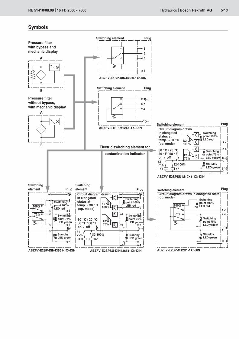
Pressure filter with bypass and mechanic display
Pressure filter without bypass, with mechanic display
Symbols
Switching element Plug
Switching point 100% LED red
Switching point 75% LED yellow
Circuit diagram drawn in elongated status at temp. > 30 °C (op. mode)
30 °C / 20 °C 86 °F / 68 °F on / off
Electric switching element for
contamination indicator
ABZFV-E1SP-M12X1-1X/-DIN
ABZFV-E2SPSU-DIN43651-1X/-DINABZFV-E2SP-DIN43651-1X/-DIN
ABZFV-E2SPSU-M12X1-1X/-DIN
ABZFV-E2SP-M12X1-1X/-DIN
Switching element Plug
Switching point 100% LED red
Switching point 75% LED yellow
Standby LED green
Standby LED green
Standby LED green
Standby LED green
Circuit diagram drawn in elongated state (op. mode)
Switching element Plug
Switching point 100% LED red
Switching point 75% LED yellow
Circuit diagram drawn in elongated status at temp. > 30 °C (op. mode)
30 °C / 20 °C 86 °F / 68 °F on / off
Switching element Plug
Switching point 100% LED red
Switching point 75% LED yellow
Switching element Plug
ABZFV-E1SP-DIN43650-1X/-DIN
Switching element Plug

6/10 Bosch Rexroth AG Hydraulics 16 FD 2500 - 7500 RE 51410/08.08
electric (electric switching element) Electrical connection Round plug-in connection M12 x 1, 4-pin
Plug-in connection according to DIN EN 175201-804, 6-pin + PE Plug-in connection according to DIN EN 175301-803, 3-pin + PE
Contact load, direct voltage A Max. 1Voltage range E1SP-M12x1 V DC/AC Max. 150
E1SP-DIN43650 V DC/AC 200 / 250E2SP V DC 10 to 30
Max. switching power with resistive load 20 VA; 20 W; (70 VA; 70 W with E1SP-DIN43650)Switching type E1SP-M12x1 Changeover
E1SP-DIN43650 OpenerE2SP-M12x1 Closer at 75% of the opening pressure,
Opener at 100 % of the opening pressureE2SP-DIN43651 Changeover at 75 and 100% of the opening pressureE2SPSU-M12x1 Closer at 75% of the opening pressure,
Opener at 100 % of the opening pressureSignal switching through at 30 °C [86 °F],Return switching at 20 °C [68 °F]
E2SPSU-DIN43651 Changeover at 75 and 100% of the opening pressureSignal switching through at 30 °C [86 °F],Return switching at 20 °C [68 °F]
Display via LED's in the electric switching element E2SP...
Stand-by (LED green); 75% switching point (LED yellow)100% switching point (LED red)
Protection type according to EN 60529 IP 65For direct voltage above 24 V a spark extinguishing is to be planned to protect the switching contacts.
Specifications (Please inquire in case the intended use of unit is outside the given values!)
Mass Electric switching element:– with round plug-in connection M12 x 1 Kg
[lbs]0.1 [0.22]
– with plug-in connection according to DIN 43651 Kg [lbs]
0.17 [0.37]

Hydraulics Bosch Rexroth AGRE 51410/08.08 16 FD 2500 - 7500 7/10
Type 16 FD…
Vol-ume in l
Weight in kg 1)
A1 A2 A3 2) A4 A5 A6 B1 B2 B3 B4 B5 B6 B7 C1 C2 C3
2500 2 x 64 285 500 435 860 1295 1385 257 972 400 403 350 323 1372 180 DN 125 Ø 273 Ø 3753000 2 x 70 325 500 435 860 1295 1385 257 1010 400 403 350 323 1410 199 DN 150 Ø 273 Ø 3754000 2 x 99 420 450 435 990 1375 1465 197 1060 400 454 350 374 1460 199 DN 150 Ø 323.9 Ø 4206000 2 x 178 505 500 480 990 1640 1730 212 1202 400 486 350 406 1602 241 DN 200 Ø 355.6 Ø 4457000 2 x 395 995 500 585 990 1675 1841 150 1450 400 639 350 559 1850 287 DN 250 Ø 508 Ø 6457500 2 x 412 1210 500 635 990 1705 1870 114 1642 400 639 350 559 2042 333 DN 300 Ø 508 Ø 645
Unit dimensions (in mm)
1) Weight including standard filter element and maintenance indicator.2) Servicing height for filter element replacement.
Inlet
Outlet
Switch lever indicates the side in use.
8/10 Bosch Rexroth AG Hydraulics 16 FD 2500 - 7500 RE 51410/08.08
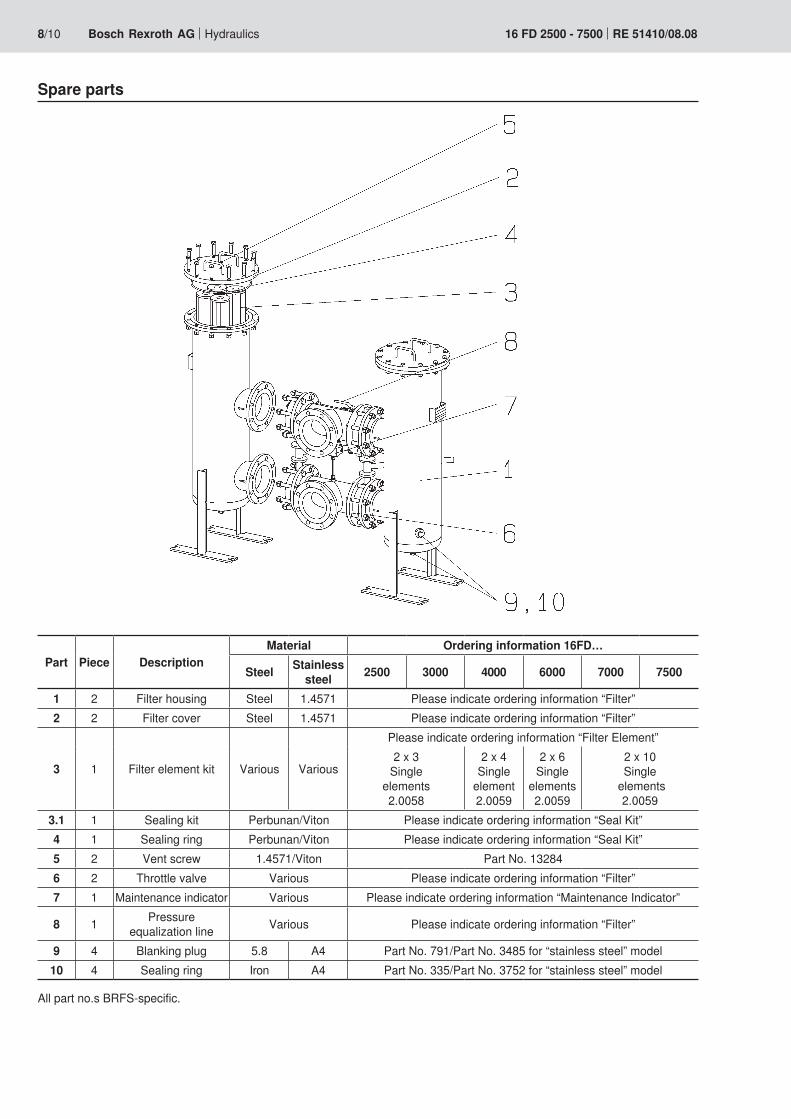
Spare parts
All part no.s BRFS-specific.
Part Piece DescriptionMaterial Ordering information 16FD…
Steel Stainless steel 2500 3000 4000 6000 7000 7500
1 2 Filter housing Steel 1.4571 Please indicate ordering information “Filter”2 2 Filter cover Steel 1.4571 Please indicate ordering information “Filter”
3 1 Filter element kit Various Various
Please indicate ordering information “Filter Element”2 x 3
Single elements 2.0058
2 x 4 Single
element 2.0059
2 x 6 Single
elements 2.0059
2 x 10 Single
elements 2.0059
3.1 1 Sealing kit Perbunan/Viton Please indicate ordering information “Seal Kit”4 1 Sealing ring Perbunan/Viton Please indicate ordering information “Seal Kit”5 2 Vent screw 1.4571/Viton Part No. 132846 2 Throttle valve Various Please indicate ordering information “Filter”7 1 Maintenance indicator Various Please indicate ordering information “Maintenance Indicator”
8 1 Pressure equalization line Various Please indicate ordering information “Filter”
9 4 Blanking plug 5.8 A4 Part No. 791/Part No. 3485 for “stainless steel” model10 4 Sealing ring Iron A4 Part No. 335/Part No. 3752 for “stainless steel” model

Hydraulics Bosch Rexroth AGRE 51410/08.08 16 FD 2500 - 7500 9/10
Spare parts (insert for DIN and SAE filters)
DIN = Mark for DIN and SAE modelSealing material
M = See table belowV = See table below
Unit series1X = Unit series 10 to 19
(10 to 19; identical installation and connection dimensions)
Mechanic-visual contamination indicator ABZ F V 1X DINRexroth Anlagenbau Accessories FilterContamination indicatorMechanic-visual contamination indicator for low-pressure filters switching point 2.2 bar [32 psi] = NV2Mechanic-visual contamination indicator for high-pressure filters switching point 5 bar [72 psi] = HV5
mechanic-visual contamination indicator Material no.
ABZFV-NV2-1X/M-DIN R901025312ABZFV-HV5-1X/M-DIN R901025313
The order details for filter elements and seal kits can be found on page 3.
Sealing material and surface coating for hydraulic liquidsOrder detail
Mineral oils Sealing material Element modelMineral oil HLP according to DIN 51524 M ...0
Flame-resistant hydraulic fluidsEmulsions HFA-E according to DIN 24320 M ...0Synthetic aqueous solutions HFA-S according to DIN 24320 M ...DAqueous solutions HFC according to VDMA 24317 M ...DPhosphate esters HFD-R according to VDMA 24317 V ...DOrganic esters HFD-U according to VDMA 24317 V ...D
Hydraulic fluids that are fast biodegradableTriglycerides (rape seed oil) HETG according to VDMA 24568 M ...D
Synthetic esters HEES according to VDMA 24568 V ...DPoly glycoles HEPG according to VDMA 24568 V ...D

Bosch Rexroth Filtration Systems GmbH & Co. KGHardtwaldstraße 43, 68775 Ketsch, GermanyPostfach 1120, 68768 Ketsch, GermanyPhone +49 (0) 62 02 / 6 03-0Fax +49 (0) 62 02 / 6 03-1 [email protected]
© This document, as well as the data, specifications and other informa-tion set forth in it, are the exclusive property of Bosch Rexroth AG. It may not be reproduced or given to third parties without its consent.The data specified above only serve to describe the product. No state-ments concerning a certain condition or suitability for a certain applica-tion can be derived from our information. The information given does not release the user from the obligation of own judgment and verification. It must be remembered that our products are subject to a natural process of wear and aging.
10/10 Bosch Rexroth AG Hydraulics 16 FD 2500 - 7500 RE 51410/08.08
Installation, starting and maintenanceInstallationVerify operating pressure with name plate information. Install the filter in the pipeline while considering the flow direction (direction arrows) and servicing height of the filter elements.
Warning!Vessel is under pressure!Assemble and disassemble filter only when system is switched off!Leave pressure equalization valve closed while filter housing is out of service!Do not operate switching device while filter housing is out of service!Do not change maintenance indicator or pressure-equaliza-tion valve when filter is under pressure!Functions and safety warranty only with BRFS-spare part!Service filter only by trained personnel!
StartingMove switching lever to central position to fill both filter sides.Switch on system pump. Pressure equalization is open. Vent filter by opening the vent screw, close when operating liquid emerges. Close pressure equalization. Move switching lever to filter in use. Switching lever must be moved into final position. Leave pressure equalization closed.
MaintenanceThe filter element is clogged and needs to be replaced or cleaned if, in operating temperature, the visual indicator’s red pin reaches its final position and/or the electrical switch is activated.
Filter Element ServiceOpen pressure equalization valve. Move switching lever to opposite direction until final position on clean filter side is reached. Close pressure equalization. Open the vent screw on the filter taken out of operation and reduce the pressure. Lift off filter cover. Open blanking plug and drain filter. Re-move filter elements, turning slightly off from their spigots in the filter housing.Check filter housing inside and clean if necessary.Replace filter element H...XL.Install cleaned or replaced filter elements by slightly turning them back on their spigots. Check o-ring on filter housing, re-place in case of damage or wear. Screw on filter cover. Open pressure equalization valve. Ventilate filter by opening the vent screw, close when operating liquid emerges. Close pres-sure equalization.
Technical modifications reserved!

Bosch Rexroth Filtration Systems GmbH & Co. KGHardtwaldstraße 43, 68775 Ketsch, GermanyPostfach 1120, 68768 Ketsch, GermanyPhone +49 (0) 62 02 / 6 03-0Fax +49 (0) 62 02 / 6 03-1 [email protected]
© This document, as well as the data, specifications and other informa-tion set forth in it, are the exclusive property of Bosch Rexroth AG. It may not be reproduced or given to third parties without its consent.The data specified above only serve to describe the product. No state-ments concerning a certain condition or suitability for a certain applica-tion can be derived from our information. The information given does not release the user from the obligation of own judgment and verification. It must be remembered that our products are subject to a natural process of wear and aging.
Hydraulics Bosch Rexroth AGRE 51410/08.08 16 FD 2500 - 7500 11/10
Notes

Bosch Rexroth Filtration Systems GmbH & Co. KGHardtwaldstraße 43, 68775 Ketsch, GermanyPostfach 1120, 68768 Ketsch, GermanyPhone +49 (0) 62 02 / 6 03-0Fax +49 (0) 62 02 / 6 03-1 [email protected]
© This document, as well as the data, specifications and other informa-tion set forth in it, are the exclusive property of Bosch Rexroth AG. It may not be reproduced or given to third parties without its consent.The data specified above only serve to describe the product. No state-ments concerning a certain condition or suitability for a certain applica-tion can be derived from our information. The information given does not release the user from the obligation of own judgment and verification. It must be remembered that our products are subject to a natural process of wear and aging.
12/10 Bosch Rexroth AG Hydraulics 16 FD 2500 - 7500 RE 51410/08.08
Notes