unit heater lh - loco.se¤rmare lh (7,8 mb).pdf · control system digipro ... a 500 630 800 1000 b...
TRANSCRIPT
1
Unit heater LH
Technology for life.

2
3
Contents LH
Contents ........................................................................................................................................................ Page
Basic unit: casing, fan, motors .................................................................................................................................................. 4
Basic unit: heat exchanger ....................................................................................................................................................... 5
Performance tables LH 25 ......................................................................................................................................................6-7
Performance tables LH 40 ......................................................................................................................................................8-9
Performance tables LH 63 ................................................................................................................................................. 10-11
Performance tables LH 100 ............................................................................................................................................... 12-13
Shut-off sets / Fastening accessories ............................................................................................................................. 14-16
Discharge accessories ........................................................................................................................................................ 17-19
Induction louvre / Consulting advice .................................................................................................................................... 20
Intake accessories ............................................................................................................................................................... 21-24
Controllers, switching and automatic - overview .............................................................................................................. 25
Switching controllers ......................................................................................................................................................... 26-29
Positioning drives for fresh air or mixed air - overview .................................................................................................... 30
Swtches for damper actuators ................................................................................................................................................ 31
Room thermostats ...................................................................................................................................................................... 32
Room thermostats, antifreeze thermostat ............................................................................................................................ 33
Intermediate terminal box, control interface box ............................................................................................................... 33
Control configuration „A“ ......................................................................................................................................................... 34
Control configuration „B“ ......................................................................................................................................................... 35
Control configuration „C“ ......................................................................................................................................................... 36
Control system DigiPro ....................................................................................................................................................... 37-41
Electrical connection / special drivers .................................................................................................................................. 42
Consulting advice ................................................................................................................................................................ 43-45
Performance and influence of accessories .......................................................................................................................... 46
Speeds table/ Sound pressure levels ...................................................................................................................................... 47
Notes on configuration ...................................................................................................................................................... 48-50
Installation examples ................................................................................................................................................................ 51
Weights ......................................................................................................................................................................................... 52
Unit descriptions .................................................................................................................................................................. 53-58
4
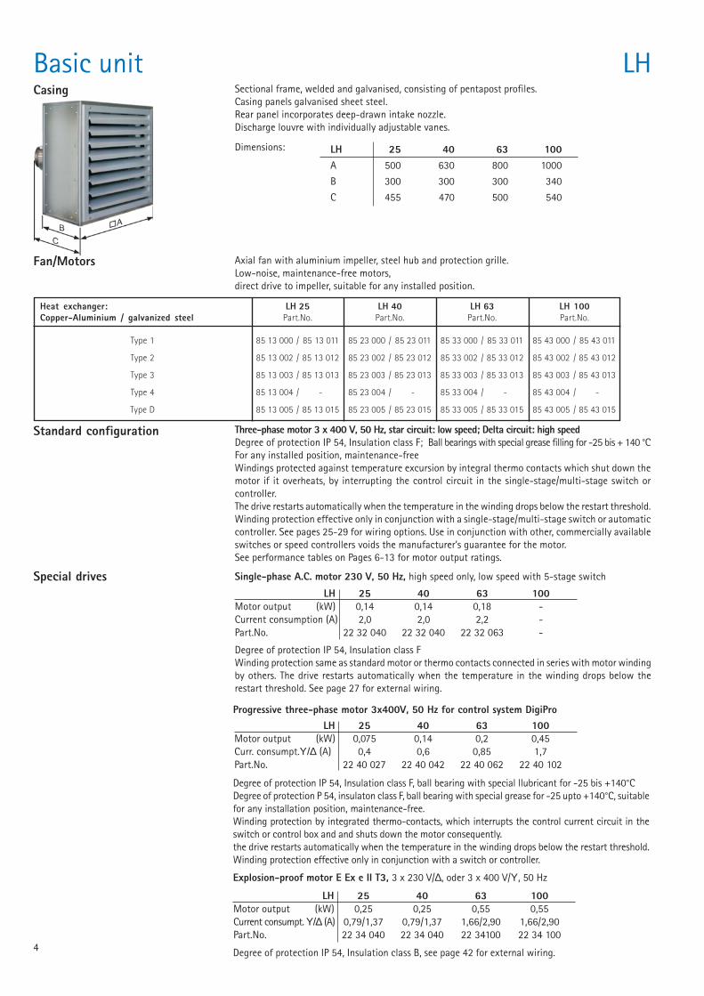
Basic unit LHCasing Sectional frame, welded and galvanised, consisting of pentapost profiles.
Casing panels galvanised sheet steel.Rear panel incorporates deep-drawn intake nozzle.Discharge louvre with individually adjustable vanes.
Dimensions: LH 25 40 63 100A 500 630 800 1000
B 300 300 300 340
C 455 470 500 540
Fan/Motors Axial fan with aluminium impeller, steel hub and protection grille.Low-noise, maintenance-free motors,direct drive to impeller, suitable for any installed position.
Heat exchanger: LH 25 LH 40 LH 63 LH 100Copper-Aluminium / galvanized steel Part.No. Part.No. Part.No. Part.No.
Type 1 85 13 000 / 85 13 011 85 23 000 / 85 23 011 85 33 000 / 85 33 011 85 43 000 / 85 43 011
Type 2 85 13 002 / 85 13 012 85 23 002 / 85 23 012 85 33 002 / 85 33 012 85 43 002 / 85 43 012
Type 3 85 13 003 / 85 13 013 85 23 003 / 85 23 013 85 33 003 / 85 33 013 85 43 003 / 85 43 013
Type 4 85 13 004 / - 85 23 004 / - 85 33 004 / - 85 43 004 / -
Type D 85 13 005 / 85 13 015 85 23 005 / 85 23 015 85 33 005 / 85 33 015 85 43 005 / 85 43 015
Standard configuration Three-phase motor 3 x 400 V, 50 Hz, star circuit: low speed; Delta circuit: high speedDegree of protection IP 54, Insulation class F; Ball bearings with special grease filling for -25 bis + 140 °CFor any installed position, maintenance-freeWindings protected against temperature excursion by integral thermo contacts which shut down themotor if it overheats, by interrupting the control circuit in the single-stage/multi-stage switch orcontroller.The drive restarts automatically when the temperature in the winding drops below the restart threshold.Winding protection effective only in conjunction with a single-stage/multi-stage switch or automaticcontroller. See pages 25-29 for wiring options. Use in conjunction with other, commercially availableswitches or speed controllers voids the manufacturer’s guarantee for the motor.See performance tables on Pages 6-13 for motor output ratings.
Special drives Single-phase A.C. motor 230 V, 50 Hz, high speed only, low speed with 5-stage switch
LH 25 40 63 100Motor output (kW) 0,14 0,14 0,18 -Current consumption (A) 2,0 2,0 2,2 -Part.No. 22 32 040 22 32 040 22 32 063 -
Degree of protection IP 54, Insulation class FWinding protection same as standard motor or thermo contacts connected in series with motor windingby others. The drive restarts automatically when the temperature in the winding drops below therestart threshold. See page 27 for external wiring.
Progressive three-phase motor 3x400V, 50 Hz for control system DigiPro
Degree of protection IP 54, Insulation class F, ball bearing with special llubricant for -25 bis +140°CDegree of protection P 54, insulaton class F, ball bearing with special grease for -25 upto +140°C, suitablefor any installation position, maintenance-free.Winding protection by integrated thermo-contacts, which interrupts the control current circuit in theswitch or control box and and shuts down the motor consequently.the drive restarts automatically when the temperature in the winding drops below the restart threshold.Winding protection effective only in conjunction with a switch or controller.
LH 25 40 63 100Motor output (kW) 0,075 0,14 0,2 0,45Curr. consumpt.Υ/∆ (A) 0,4 0,6 0,85 1,7Part.No. 22 40 027 22 40 042 22 40 062 22 40 102
LH 25 40 63 100Motor output (kW) 0,25 0,25 0,55 0,55Current consumpt. Υ/∆ (A) 0,79/1,37 0,79/1,37 1,66/2,90 1,66/2,90Part.No. 22 34 040 22 34 040 22 34100 22 34 100
Degree of protection IP 54, Insulation class B, see page 42 for external wiring.
Explosion-proof motor E Ex e II T3, 3 x 230 V/∆, oder 3 x 400 V/Υ, 50 Hz
5
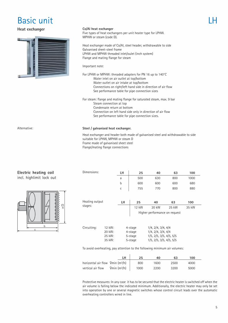
Basic unit LHHeat exchanger Co/Al heat exchanger
Five types of heat exchangers per unit heater type for LPHW.MPHW or steam (code D).
Heat exchanger made of Co/Al, steel header, withdrawable to sideGalvanised sheet-steel frameLPHW and MPHW threaded inlet/oulet (inch system)Flange and mating flange for steam
Important note:
For LPHW or MPHW: threaded adapters for PN 16 up to 140°CWater inlet on air outlet at top/bottomWater outlet on air intake at top/bottomConnections on right/left hand side in direction of air flowSee performance table for pipe connection sizes
For steam: flange and mating flange for saturated steam, max. 9 barSteam connection at topCondensate return at bottomConnection on left hand side only in direction of air flowSee performance table for pipe connection sizes.
Steel / galvanised heat exchanger.
Heat exchanger and header both made of galvanised steel and withdrawable to sidesuitable for LPHW, MPHW or steam DFrame made of galvanised sheet steelFlange/mating flange connections
Alternative:
Electric heating coilincl. highlimit lock out
Dimensions: LH 25 40 63 100a 500 630 800 1000
b 600 600 600 680
c 755 770 800 880
Heating outputstages:
LH 25 40 63 10012 kW 20 kW 25 kW 35 kW
Higher performance on request
Circuiting: 12 kW: 4-stage 1/4, 2/4, 3/4, 4/420 kW: 4-stage 1/4, 2/4, 3/4, 4/425 kW: 5-stage 1/5, 2/5, 3/5, 4/5, 5/535 kW: 5-stage 1/5, 2/5, 3/5, 4/5, 5/5
To avoid overheating, pay attention to the following minimum air volumes:
LH 25 40 63 100horizontal air flow Vmin (m³/h) 800 1600 2500 4000
vertical air flow Vmin (m³/h) 1000 2200 3200 5000
··
Protective measures: In any case it has to be secured that the electric heater is switched off when theair volume is falling below the indicated minimum. Additionally, the electric heater may only be setinto operation by one or several magnetic switches whose control circuit leads over the automaticoverheating controllers wired in line.
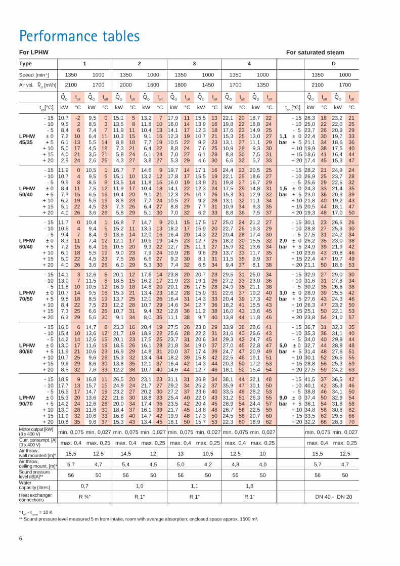
6
Performance tables
Speed [min-1] 1350 1000 1350 1000 1350 1000 1350 1000 1350 1000
Air vol. VO [m³/h] 2100 1700 2000 1600 1800 1450 1700 1350 2100 1700
Type 1 2 3 4 D
min. 0,075 min. 0,027 min. 0,075 min. 0,027 min. 0,075 min. 0,027 min. 0,075 min. 0,027 min. 0,075 min. 0,027
max. 0,4 max. 0,25 max. 0,4 max. 0,25 max. 0,4 max. 0,25 max. 0,4 max. 0,25 max. 0,4 max. 0,25
15,5 12,5 14,5 12 13 10,5 12,5 10 15,5 12,5
5,7 4,7 5,4 4,5 5,0 4,2 4,8 4,0 5,7 4,7
56 50 56 50 56 50 56 50 56 50
0,7 1,0 1,1 1,8
R ¾“ R 1“ R 1“ R 1“ DN 40 - DN 20
Motor output [kW](3 x 400 V)Curr. consumpt. [A](3 x 400 V)Air throw,wall mounted [m]*Air throw,ceiling mount. [m]*Sound pressurelevel dB[A]**Watercapacity [litres]
For LPHW
* toff - troom = 10 K** Sound pressure level measured 5 m from intake, room with average absorption; enclosed space approx. 1500 m³.
For saturated steam
Heat exchangerconnections
QO toff QO toff QO toff QO toff QO toff QO toff QO toff QO toff QO toff QO toff
ton[°C] kW °C kW °C kW °C kW °C kW °C kW °C kW °C kW °C ton [°C] kW °C kW °C
- 15 10,7 -2 9,5 0 15,1 5 13,2 7 17,9 11 15,5 13 22,1 20 18,7 22 - 15 26,3 18 23,2 21- 10 9,5 2 8,5 3 13,5 8 11,8 10 16,0 14 13,9 16 19,8 22 16,8 24 - 10 25,0 22 22,0 25- 5 8,4 6 7,4 7 11,9 11 10,4 13 14,1 17 12,3 18 17,6 23 14,9 25 - 5 23,7 26 20,9 29
LPHW ± 0 7,2 10 6,4 11 10,3 15 9,1 16 12,3 19 10,7 21 15,3 25 13,0 27 1,1 ± 0 22,4 30 19,7 3345/35 + 5 6,1 13 5,5 14 8,8 18 7,7 19 10,5 22 9,2 23 13,1 27 11,1 29 bar + 5 21,1 34 18,6 36
+ 10 5,0 17 4,5 18 7,3 21 6,4 22 8,8 24 7,6 25 10,9 29 9,3 30 + 10 19,9 38 17,5 40+ 15 4,0 21 3,5 21 5,8 24 5,1 24 7,0 27 6,1 28 8,8 30 7,5 31 + 15 18,6 41 16,4 44+ 20 2,9 24 2,6 25 4,3 27 3,8 27 5,3 29 4,6 30 6,6 32 5,7 33 + 20 17,4 45 15,3 47
- 15 11,9 0 10,5 1 16,7 7 14,6 9 19,7 14 17,1 16 24,4 23 20,5 25 - 15 28,2 21 24,9 24- 10 10,7 4 9,5 5 15,1 10 13,2 12 17,8 17 15,5 19 22,1 25 18,6 27 - 10 26,9 25 23,7 28- 5 9,5 8 8,5 9 13,5 14 11,8 15 16,0 19 13,9 21 19,8 27 16,7 29 - 5 25,6 29 22,5 32
LPHW ± 0 8,4 11 7,5 12 11,9 17 10,4 18 14,1 22 12,3 24 17,5 29 14,8 31 1,5 ± 0 24,3 33 21,4 3550/40 + 5 7,3 15 6,5 16 10,4 20 9,1 21 12,3 25 10,7 26 15,3 31 12,9 32 bar + 5 23,0 36 20,3 39
+ 10 6,2 19 5,5 19 8,8 23 7,7 24 10,5 27 9,2 28 13,1 32 11,1 34 + 10 21,8 40 19,2 43+ 15 5,1 22 4,5 23 7,3 26 6,4 27 8,8 29 7,7 31 10,9 34 9,3 35 + 15 20,5 44 18,1 47+ 20 4,0 26 3,6 26 5,8 29 5,1 30 7,0 32 6,2 33 8,8 36 7,5 37 + 20 19,3 48 17,0 50
- 15 11,7 0 10,4 1 16,8 7 14,7 9 20,1 15 17,5 17 25,0 24 21,2 27 - 15 30,1 23 26,5 26- 10 10,6 4 9,4 5 15,2 11 13,3 13 18,2 17 15,9 20 22,7 26 19,3 29 - 10 28,8 27 25,3 30- 5 9,4 7 8,4 9 13,6 14 12,0 16 16,4 20 14,3 22 20,4 28 17,4 30 - 5 27,5 31 24,2 34
LPHW ± 0 8,3 11 7,4 12 12,1 17 10,6 19 14,5 23 12,7 25 18,2 30 15,5 32 2,0 ± 0 26,2 35 23,0 3860/40 + 5 7,2 15 6,4 16 10,5 20 9,3 22 12,7 25 11,1 27 15,9 32 13,6 34 bar + 5 24,9 39 21,9 42
+ 10 6,1 18 5,5 19 9,0 23 7,9 24 10,9 28 9,6 29 13,7 33 11,7 35 + 10 23,6 43 20,8 46+ 15 5,0 22 4,5 23 7,5 26 6,6 27 9,2 30 8,1 31 11,5 35 9,9 37 + 15 22,4 47 19,7 49+ 20 4,0 26 3,6 26 6,0 29 5,3 30 7,4 32 6,5 34 9,4 37 8,1 38 + 20 21,1 50 18,6 53
- 15 14,1 3 12,6 5 20,1 12 17,6 14 23,8 20 20,7 23 29,5 31 25,0 34 - 15 32,9 27 29,0 30- 10 13,0 7 11,5 8 18,5 15 16,2 17 21,9 23 19,1 26 27,2 33 23,0 36 - 10 31,6 31 27,8 34- 5 11,8 10 10,5 12 16,9 18 14,8 20 20,1 26 17,5 28 24,9 35 21,1 38 - 5 30,2 35 26,6 38
LPHW ± 0 10,7 14 9,5 16 15,3 21 13,4 23 18,2 28 15,9 31 22,6 37 19,2 40 3,0 ± 0 28,9 39 25,5 4270/50 + 5 9,5 18 8,5 19 13,7 25 12,0 26 16,4 31 14,3 33 20,4 39 17,3 42 bar + 5 27,6 43 24,3 46
+ 10 8,4 22 7,5 23 12,2 28 10,7 29 14,6 34 12,7 36 18,2 41 15,5 43 + 10 26,3 47 23,2 50+ 15 7,3 25 6,6 26 10,7 31 9,4 32 12,8 36 11,2 38 16,0 43 13,6 45 + 15 25,1 50 22,1 53+ 20 6,3 29 5,6 30 9,1 34 8,0 35 11,1 38 9,7 40 13,8 44 11,8 46 + 20 23,8 54 21,0 57
- 15 16,6 6 14,7 8 23,3 16 20,4 19 27,5 26 23,8 29 33,9 38 28,6 41 - 15 36,7 31 32,3 35- 10 15,4 10 13,6 12 21,7 19 18,9 22 25,6 28 22,2 31 31,6 40 26,6 43 - 10 35,3 36 31,1 40- 5 14,2 14 12,6 15 20,1 23 17,5 25 23,7 31 20,6 34 29,3 42 24,7 45 - 5 34,0 40 29,9 44
LPHW ± 0 13,0 17 11,6 19 18,5 26 16,1 28 21,8 34 19,0 37 27,0 45 22,8 47 5,0 ± 0 32,7 44 28,8 4880/60 + 5 11,9 21 10,6 23 16,9 29 14,8 31 20,0 37 17,4 39 24,7 47 20,9 49 bar + 5 31,4 48 27,6 51
+ 10 10,7 25 9,6 26 15,3 32 13,4 34 18,2 39 15,8 42 22,5 48 19,1 51 + 10 30,1 52 26,5 55+ 15 9,6 29 8,6 30 13,8 35 12,1 37 16,4 42 14,3 44 20,3 50 17,2 53 + 15 28,8 56 25,3 59+ 20 8,5 32 7,6 33 12,2 38 10,7 40 14,6 44 12,7 46 18,1 52 15,4 54 + 20 27,5 59 24,2 63
- 15 18,9 9 16,8 11 26,5 20 23,1 23 31,1 31 26,9 34 38,1 44 32,1 48 - 15 41,5 37 36,5 42- 10 17,7 13 15,7 15 24,9 24 21,7 27 29,2 34 25,2 37 35,9 47 30,1 50 - 10 40,1 42 35,3 46- 5 16,5 17 14,7 19 23,2 27 20,2 30 27,2 37 23,6 40 33,5 49 28,2 53 - 5 38,8 46 34,1 50
LPHW ± 0 15,3 20 13,6 22 21,6 30 18,8 33 25,4 40 22,0 43 31,2 51 26,3 55 9,0 ± 0 37,4 50 32,9 5490/70 + 5 14,2 24 12,6 26 20,0 34 17,4 36 23,5 42 20,4 45 28,9 54 24,4 57 bar + 5 36,1 54 31,8 58
+ 10 13,0 28 11,6 30 18,4 37 16,1 39 21,7 45 18,8 48 26,7 56 22,5 59 + 10 34,8 58 30,6 62+ 15 11,9 32 10,6 33 16,8 40 14,7 42 19,9 48 17,3 50 24,5 58 20,7 60 + 15 33,5 62 29,5 66+ 20 10,8 35 9,6 37 15,3 43 13,4 45 18,1 50 15,7 53 22,3 60 18,9 62 + 20 32,2 66 28,3 70
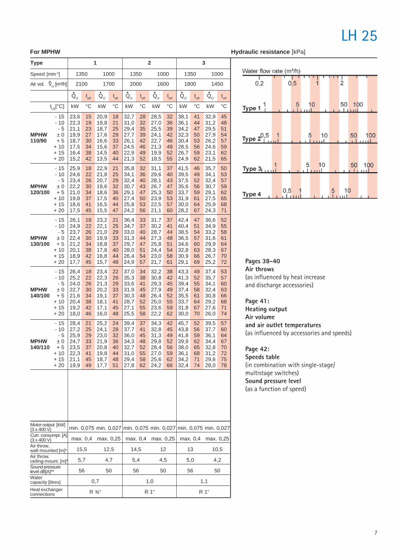
7
Type 1 2 3
LH 25
Speed [min-1] 1350 1000 1350 1000 1350 1000
Air vol. VO [m³/h] 2100 1700 2000 1600 1800 1450
Motor output [kW](3 x 400 V)Curr. consumpt. [A](3 x 400 V)Air throw,wall-mounted [m]*Air throw,ceiling-mount. [m]*Sound pressurelevel dB[A]**Watercapacity [litres]
Heat exchangerconnections
min. 0,075 min. 0,027 min. 0,075 min. 0,027 min. 0,075 min. 0,027
max. 0,4 max. 0,25 max. 0,4 max. 0,25 max. 0,4 max. 0,25
15,5 12,5 14,5 12 13 10,5
5,7 4,7 5,4 4,5 5,0 4,2
56 50 56 50 56 50
0,7 1,0 1,1
R ¾“ R 1“ R 1“
For MPHW Hydraulic resistance [kPa]
Pages 38-40Air throws(as influenced by heat increaseand discharge accessories)
Page 41:Heating outputAir volumeand air outlet temperatures(as influenced by accessories and speeds)
Page 42:Speeds table(in combination with single-stage/multistage switches)Sound pressure level(as a function of speed)
QO toff QO toff QO toff QO toff QO toff QO toff
tLE[°C] kW °C kW °C kW °C kW °C kW °C kW °C
- 15 23,6 15 20,9 18 32,7 28 28,5 32 38,1 41 32,9 45- 10 22,3 19 19,8 21 31,0 32 27,0 36 36,1 44 31,2 48- 5 21,1 23 18,7 25 29,4 35 25,5 39 34,2 47 29,5 51
MPHW ± 0 19,9 27 17,6 29 27,7 39 24,1 42 32,3 50 27,9 54110/90 + 5 18,7 30 16,6 33 26,1 42 22,7 46 30,4 53 26,2 57
+ 10 17,5 34 15,6 37 24,5 46 21,3 49 28,5 56 24,6 59+ 15 16,4 38 14,5 40 22,9 49 19,9 52 26,7 59 23,1 62+ 20 15,2 42 13,5 44 21,3 52 18,5 55 24,9 62 21,5 65
- 15 25,9 18 22,9 21 35,8 32 31,1 37 41,5 46 35,7 50- 10 24,6 22 21,8 25 34,1 36 29,6 40 39,5 49 34,1 53- 5 23,4 26 20,7 29 32,4 40 28,1 43 37,5 52 32,4 57
MPHW ± 0 22,2 30 19,6 32 30,7 43 26,7 47 35,6 56 30,7 59120/100 + 5 21,0 34 18,6 36 29,1 47 25,3 50 33,7 59 29,1 62
+ 10 19,8 37 17,5 40 27,4 50 23,9 53 31,9 61 27,5 65+ 15 18,6 41 16,5 44 25,8 53 22,5 57 30,0 64 25,9 68+ 20 17,5 45 15,5 47 24,2 56 21,1 60 28,2 67 24,3 71
- 15 26,1 18 23,2 21 36,4 33 31,7 37 42,4 47 36,6 52- 10 24,9 22 22,1 25 34,7 37 30,2 41 40,4 51 34,9 55- 5 23,7 26 21,0 29 33,0 40 28,7 44 38,5 54 33,2 58
MPHW ± 0 22,4 30 19,9 33 31,3 44 27,3 48 36,5 57 31,6 61130/100 + 5 21,2 34 18,8 37 29,7 47 25,8 51 34,6 60 29,9 64
+ 10 20,1 38 17,8 40 28,0 51 24,4 54 32,8 63 28,3 67+ 15 18,9 42 16,8 44 26,4 54 23,0 58 30,9 66 26,7 70+ 20 17,7 45 15,7 48 24,9 57 21,7 61 29,1 69 25,2 72
- 15 26,4 18 23,4 22 37,0 34 32,2 38 43,3 49 37,4 53- 10 25,2 22 22,3 26 35,3 38 30,8 42 41,3 52 35,7 57- 5 24,0 26 21,3 29 33,6 41 29,3 45 39,4 55 34,1 60
MPHW ± 0 22,7 30 20,2 33 31,9 45 27,9 49 37,4 58 32,4 63140/100 + 5 21,6 34 19,1 37 30,3 48 26,4 52 35,5 61 30,8 66
+ 10 20,4 38 18,1 41 28,7 52 25,0 55 33,7 64 29,2 68+ 15 19,2 42 17,1 45 27,1 55 23,6 59 31,8 67 27,6 71+ 20 18,0 46 16,0 48 25,5 58 22,2 62 30,0 70 26,0 74
- 15 28,4 21 25,2 24 39,4 37 34,3 42 45,7 52 39,5 57- 10 27,2 25 24,1 28 37,7 41 32,8 45 43,8 56 37,7 60- 5 25,9 29 23,0 32 36,0 45 31,3 49 41,8 59 36,1 64
MPHW ± 0 24,7 33 21,9 36 34,3 48 29,8 52 39,9 62 34,4 67140/110 + 5 23,5 37 20,8 40 32,7 52 28,4 56 38,0 65 32,8 70
+ 10 22,3 41 19,8 44 31,0 55 27,0 59 36,1 68 31,2 72+ 15 21,1 45 18,7 48 29,4 58 25,6 62 34,2 71 29,6 75+ 20 19,9 49 17,7 51 27,8 62 24,2 66 32,4 74 28,0 78
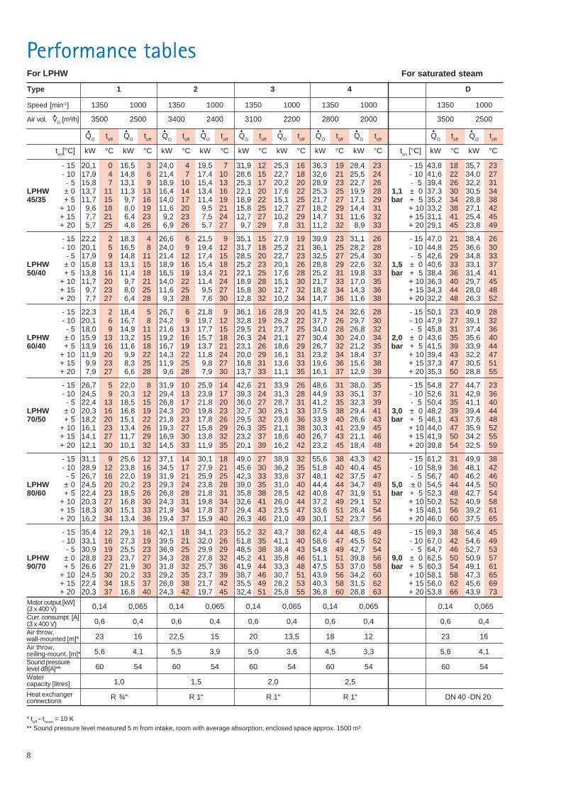
8
Performance tables
Speed [min-1] 1350 1000 1350 1000 1350 1000 1350 1000 1350 1000
Air vol. VO [m³/h] 3500 2500 3400 2400 3100 2200 2800 2000 3500 2500
Type 1 2 3 4 D
0,14 0,065 0,14 0,065 0,14 0,065 0,14 0,065 0,14 0,065
0,6 0,4 0,6 0,4 0,6 0,4 0,6 0,4 0,6 0,4
23 16 22,5 15 20 13,5 18 12 23 16
5,6 4,1 5,5 3,9 5,0 3,6 4,5 3,3 5,6 4,1
60 54 60 54 60 54 60 54 60 54
1,0 1,5 2,0 2,5
R ¾“ R 1“ R 1“ R 1“ DN 40 -DN 20
Motor output [kW](3 x 400 V)Curr. consumpt. [A](3 x 400 V)Air throw,wall-mounted [m]*Air throw,ceiling-mount. [m]*Sound pressurelevel dB[A]**Watercapacity [litres]
For LPHW
* toff - troom = 10 K** Sound pressure level measured 5 m from intake, room with average absorption; enclosed space approx. 1500 m³
For saturated steam
Heat exchangerconnections
QO toff QO toff QO toff QO toff QO toff QO toff QO toff QO toff QO toff QO toff
ton[°C] kW °C kW °C kW °C kW °C kW °C kW °C kW °C kW °C ton [°C] kW °C kW °C
- 15 20,1 0 16,5 3 24,0 4 19,5 7 31,9 12 25,3 16 36,3 19 28,4 23 - 15 43,8 18 35,7 23- 10 17,9 4 14,8 6 21,4 7 17,4 10 28,6 15 22,7 18 32,6 21 25,5 24 - 10 41,6 22 34,0 27- 5 15,8 7 13,1 9 18,9 10 15,4 13 25,3 17 20,2 20 28,9 23 22,7 26 - 5 39,4 26 32,2 31
LPHW ± 0 13,7 11 11,3 13 16,4 14 13,4 16 22,1 20 17,6 22 25,3 25 19,9 28 1,1 ± 0 37,3 30 30,5 3445/35 + 5 11,7 15 9,7 16 14,0 17 11,4 19 18,9 22 15,1 25 21,7 27 17,1 29 bar + 5 35,2 34 28,8 38
+ 10 9,6 18 8,0 19 11,6 20 9,5 21 15,8 25 12,7 27 18,2 29 14,4 31 + 10 33,2 38 27,1 42+ 15 7,7 21 6,4 23 9,2 23 7,5 24 12,7 27 10,2 29 14,7 31 11,6 32 + 15 31,1 41 25,4 45+ 20 5,7 25 4,8 26 6,9 26 5,7 27 9,7 29 7,8 31 11,2 32 8,9 33 + 20 29,1 45 23,8 49
- 15 22,2 2 18,3 4 26,6 6 21,5 9 35,1 15 27,9 19 39,9 23 31,1 26 - 15 47,0 21 38,4 26- 10 20,1 5 16,5 8 24,0 9 19,4 12 31,7 18 25,2 21 36,1 25 28,2 28 - 10 44,8 25 36,6 30- 5 17,9 9 14,8 11 21,4 12 17,4 15 28,5 20 22,7 23 32,5 27 25,4 30 - 5 42,6 29 34,8 33
LPHW ± 0 15,8 13 13,1 15 18,9 16 15,4 18 25,2 23 20,1 26 28,8 29 22,6 32 1,5 ± 0 40,6 33 33,1 3750/40 + 5 13,8 16 11,4 18 16,5 19 13,4 21 22,1 25 17,6 28 25,2 31 19,8 33 bar + 5 38,4 36 31,4 41
+ 10 11,7 20 9,7 21 14,0 22 11,4 24 18,9 28 15,1 30 21,7 33 17,0 35 + 10 36,3 40 29,7 45+ 15 9,7 23 8,0 25 11,6 25 9,5 27 15,8 30 12,7 32 18,2 34 14,3 36 + 15 34,3 44 28,0 48+ 20 7,7 27 6,4 28 9,3 28 7,6 30 12,8 32 10,2 34 14,7 36 11,6 38 + 20 32,2 48 26,3 52
- 15 22,3 2 18,4 5 26,7 6 21,8 9 36,1 16 28,9 20 41,5 24 32,6 28 - 15 50,1 23 40,9 28- 10 20,1 6 16,7 8 24,2 9 19,7 12 32,8 19 26,2 22 37,7 26 29,7 30 - 10 47,9 27 39,1 32- 5 18,0 9 14,9 11 21,6 13 17,7 15 29,5 21 23,7 25 34,0 28 26,8 32 - 5 45,8 31 37,4 36
LPHW ± 0 15,9 13 13,2 15 19,2 16 15,7 18 26,3 24 21,1 27 30,4 30 24,0 34 2,0 ± 0 43,6 35 35,6 4060/40 + 5 13,9 16 11,6 18 16,7 19 13,7 21 23,1 26 18,6 29 26,7 32 21,2 35 bar + 5 41,5 39 33,9 44
+ 10 11,9 20 9,9 22 14,3 22 11,8 24 20,0 29 16,1 31 23,2 34 18,4 37 + 10 39,4 43 32,2 47+ 15 9,9 23 8,3 25 11,9 25 9,8 27 16,8 31 13,6 33 19,6 36 15,6 38 + 15 37,3 47 30,5 51+ 20 7,9 27 6,6 28 9,6 28 7,9 30 13,7 33 11,1 35 16,1 37 12,9 39 + 20 35,3 50 28,8 55
- 15 26,7 5 22,0 8 31,9 10 25,9 14 42,6 21 33,9 26 48,6 31 38,0 35 - 15 54,8 27 44,7 23- 10 24,5 9 20,3 12 29,4 13 23,9 17 39,3 24 31,3 28 44,9 33 35,1 37 - 10 52,6 31 42,9 36- 5 22,4 13 18,5 15 26,8 17 21,8 20 36,0 27 28,7 31 41,2 35 32,3 39 - 5 50,4 35 41,1 40
LPHW ± 0 20,3 16 16,8 19 24,3 20 19,8 23 32,7 30 26,1 33 37,5 38 29,4 41 3,0 ± 0 48,2 39 39,4 4470/50 + 5 18,2 20 15,1 22 21,8 23 17,8 26 29,5 32 23,6 36 33,9 40 26,6 43 bar + 5 46,1 43 37,6 48
+ 10 16,1 23 13,4 26 19,3 27 15,8 29 26,3 35 21,1 38 30,3 41 23,9 45 + 10 44,0 47 35,9 52+ 15 14,1 27 11,7 29 16,9 30 13,8 32 23,2 37 18,6 40 26,7 43 21,1 46 + 15 41,9 50 34,2 55+ 20 12,1 30 10,1 32 14,5 33 11,9 35 20,1 39 16,2 42 23,2 45 18,4 48 + 20 39,8 54 32,5 59
- 15 31,1 9 25,6 12 37,1 14 30,1 18 49,0 27 38,9 32 55,6 38 43,3 42 - 15 61,2 31 49,9 38- 10 28,9 12 23,8 16 34,5 17 27,9 21 45,6 30 36,2 35 51,8 40 40,4 45 - 10 58,9 36 48,1 42- 5 26,7 16 22,0 19 31,9 21 25,9 25 42,3 33 33,6 37 48,1 42 37,5 47 - 5 56,7 40 46,2 46
LPHW ± 0 24,5 20 20,2 23 29,3 24 23,8 28 39,0 35 31,0 40 44,4 44 34,7 49 5,0 ± 0 54,5 44 44,5 5080/60 + 5 22,4 23 18,5 26 26,8 28 21,8 31 35,8 38 28,5 42 40,8 47 31,9 51 bar + 5 52,3 48 42,7 54
+ 10 20,3 27 16,8 30 24,3 31 19,8 34 32,6 41 26,0 44 37,2 49 29,1 52 + 10 50,2 52 40,9 58+ 15 18,3 30 15,1 33 21,9 34 17,8 37 29,4 43 23,5 47 33,6 51 26,4 54 + 15 48,1 56 39,2 61+ 20 16,2 34 13,4 36 19,4 37 15,9 40 26,3 46 21,0 49 30,1 52 23,7 56 + 20 46,0 60 37,5 65
- 15 35,4 12 29,1 16 42,1 18 34,1 23 55,2 32 43,7 38 62,4 44 48,5 49 - 15 69,3 38 56,4 45- 10 33,1 16 27,3 19 39,5 21 32,0 26 51,8 35 41,1 40 58,6 47 45,5 52 - 10 67,0 42 54,6 49- 5 30,9 19 25,5 23 36,9 25 29,9 29 48,5 38 38,4 43 54,8 49 42,7 54 - 5 64,7 46 52,7 53
LPHW ± 0 28,8 23 23,7 27 34,3 28 27,8 32 45,2 41 35,8 46 51,1 51 39,8 56 9,0 ± 0 62,5 50 50,9 5790/70 + 5 26,6 27 21,9 30 31,8 32 25,7 36 41,9 44 33,3 48 47,5 53 37,0 58 bar + 5 60,3 54 49,1 61
+ 10 24,5 30 20,2 33 29,2 35 23,7 39 38,7 46 30,7 51 43,9 56 34,2 60 + 10 58,1 58 47,3 65+ 15 22,4 34 18,5 37 26,8 38 21,7 42 35,5 49 28,2 53 40,3 58 31,5 62 + 15 56,0 62 45,6 69+ 20 20,3 37 16,8 40 24,3 42 19,7 45 32,4 51 25,8 55 36,8 60 28,8 63 + 20 53,8 66 43,9 73
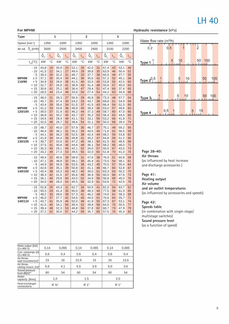
9
LH 40
Type 1 2 3
Speed [min-1] 1350 1000 1350 1000 1350 1000
Air vol. VO [m³/h] 3500 2500 3400 2400 3100 2200
Motor output [kW](3 x 400 V)Curr. consumpt. [A](3 x 400 V)Air throw,wall-mounted [m]*Air throw,ceiling-mount. [m]*Sound-pressurelevel dB[A]**Watercapacity [litres]
Heat exchangerconnections
0,14 0,065 0,14 0,065 0,14 0,065
0,6 0,4 0,6 0,4 0,6 0,4
23 16 22,5 15 20 13,5
5,6 4,1 5,5 3,9 5,0 3,6
60 54 60 54 60 54
1,0 1,5 2,0
R ¾“ R 1“ R 1“
For MPHW Hydraulic resistance [kPa]
Page 38-40:Air throws(as influenced by heat increaseand discharge accessories )
Page 41:Heating outputAir volumeand air outlet temperatures(as influenced by accessories and speeds)
Page 42:Speeds table(in combination with single-stage/multistage switches)Sound pressure level(as a function of speed)
QO tLA QO tLA QO tLA QO tLA QO tLA QO tLA
tLE[°C] kW °C kW °C kW °C kW °C kW °C kW °C
- 15 43,8 18 35,9 23 52,1 26 42,0 31 67,4 43 53,1 49- 10 41,5 22 34,1 27 49,4 29 39,8 35 63,9 46 50,4 52- 5 39,3 26 32,2 31 46,7 33 37,7 38 60,5 49 47,7 55
MPHW ± 0 37,1 30 30,4 34 44,1 36 35,6 42 57,2 52 45,1 58110/90 + 5 34,9 33 28,6 38 41,5 40 33,5 45 53,8 55 42,5 60
+ 10 32,7 37 26,9 41 38,9 43 31,4 48 50,6 57 40,0 63+ 15 30,6 41 25,1 45 36,4 47 29,4 51 47,4 60 37,4 65+ 20 28,5 44 23,4 48 33,9 50 27,4 54 44,2 63 34,9 68
- 15 48,0 21 39,3 27 56,9 29 45,8 36 73,3 48 57,7 54- 10 45,7 25 37,4 30 54,2 33 43,7 39 69,8 51 54,9 58- 5 43,4 29 35,6 34 51,5 37 41,5 43 66,4 54 52,3 60
MPHW ± 0 41,2 33 33,8 38 48,9 40 39,4 46 63,0 57 49,6 63120/100 + 5 39,0 37 31,9 42 46,2 44 37,3 49 59,7 60 47,0 66
+ 10 36,8 41 30,2 45 43,7 47 35,2 53 56,4 63 44,5 69+ 15 34,6 44 28,4 49 41,1 51 33,1 56 53,2 66 41,9 71+ 20 32,5 48 26,7 52 38,6 54 31,1 59 50,0 68 39,4 74
- 15 48,7 22 40,0 27 57,9 30 46,7 37 75,1 49 59,2 56- 10 46,4 26 38,1 31 55,2 34 44,5 40 71,6 52 56,5 59- 5 44,1 30 36,2 35 52,5 38 42,4 44 68,2 56 53,8 62
MPHW ± 0 41,9 34 34,4 39 49,8 41 40,2 47 64,8 59 51,2 65130/100 + 5 39,7 37 32,6 42 47,2 45 38,1 50 61,5 62 48,6 68
+ 10 37,5 41 30,8 46 44,6 48 36,1 54 58,2 65 46,0 71+ 15 35,3 45 29,1 49 42,1 52 34,0 57 55,0 67 43,5 73+ 20 33,2 49 27,3 53 39,5 55 32,0 60 51,8 70 41,0 76
- 15 49,4 22 40,6 28 58,9 31 47,6 38 76,9 51 60,8 58- 10 47,1 26 38,8 32 56,1 35 45,4 41 73,5 54 58,1 61- 5 44,9 30 36,9 36 53,5 38 43,2 45 70,0 57 55,4 64
MPHW ± 0 42,6 34 35,1 39 50,8 42 41,1 48 66,7 60 52,8 67140/100 + 5 40,4 38 33,3 43 48,2 45 39,0 51 63,3 63 50,2 70
+ 10 38,3 42 31,5 47 45,6 49 36,9 55 60,0 66 47,6 73+ 15 36,1 46 29,8 50 43,0 52 34,9 58 56,8 69 45,0 76+ 20 34,0 49 28,0 54 40,5 56 32,9 61 53,6 72 42,5 78
- 15 52,8 25 43,3 31 62,7 34 50,5 41 81,0 54 63,7 62- 10 50,5 29 41,4 35 60,0 38 48,3 44 77,5 58 61,0 65- 5 48,2 33 39,6 39 57,3 41 46,2 48 74,0 61 58,3 68
MPHW ± 0 46,0 37 37,7 42 54,6 45 44,0 51 70,6 64 55,7 71140/110 + 5 43,7 41 35,9 46 52,0 49 41,9 55 67,3 67 53,1 74
+ 10 41,5 45 34,1 50 49,4 52 39,8 58 64,0 70 50,5 77+ 15 39,4 48 32,3 53 46,8 56 37,8 62 60,7 73 47,9 79+ 20 37,2 52 30,6 57 44,2 59 35,7 65 57,5 76 45,4 82
10
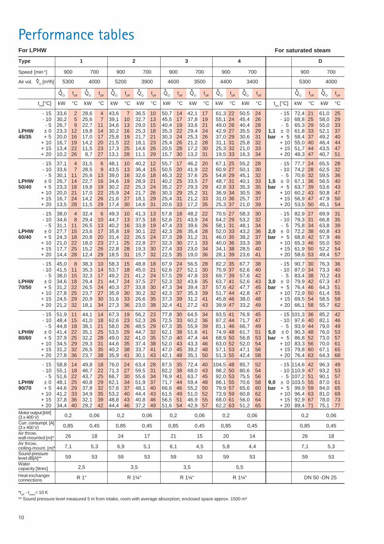
Performance tables
Speed [min-1] 900 700 900 700 900 700 900 700 900 700
Air vol. VO [m³/h] 5300 4000 5200 3900 4600 3500 4400 3400 5300 4000
Type 1 2 3 4 D
0,2 0,06 0,2 0,06 0,2 0,06 0,2 0,06 0,2 0,06
0,85 0,45 0,85 0,45 0,85 0,45 0,85 0,45 0,85 0,45
26 18 24 17 21 15 20 14 26 18
7,1 5,3 6,9 5,1 6,1 4,5 5,8 4,4 7,1 5,3
59 53 59 53 59 53 59 53 59 53
2,5 3,5 3,5 5,5
R 1“ R 1¼“ R 1¼“ R 1¼“ DN 50 -DN 25
Motor output [kW](3 x 400 V)Curr. consumpt. [A](3 x 400 V)Air throw,wall-mounted [m]*Air throw,ceiling-mount. [m]*Sound-pressurelevel dB[A]**Watercapacity [litres]
For LPHW
*toff - troom= 10 K** Sound pressure level measured 5 m from intake, room with average absorption; enclosed space approx. 1500 m³
For saturated steam
Heat exchangerconnections
QO toff QO toff QO toff QO toff QO toff QO toff QO toff QO toff QO toff QO toff
ton[°C] kW °C kW °C kW °C kW °C kW °C kW °C kW °C kW °C ton [°C] kW °C kW °C
- 15 33,6 2 28,6 4 43,6 7 36,5 10 50,7 14 42,1 17 61,3 22 50,5 24 - 15 72,4 21 61,0 25- 10 30,2 5 25,6 7 39,1 10 32,7 13 45,5 17 37,8 19 55,1 24 45,4 26 - 10 68,8 25 58,0 29- 5 26,7 9 22,7 11 34,6 13 29,0 15 40,4 19 33,6 21 49,0 26 40,4 28 - 5 65,3 29 55,0 33
LPHW ± 0 23,3 12 19,8 14 30,2 16 25,3 18 35,3 22 29,4 24 42,9 27 35,5 29 1,1 ± 0 61,8 33 52,1 3745/35 + 5 20,0 16 17,0 17 25,8 19 21,7 21 30,3 24 25,3 26 37,0 29 30,6 31 bar + 5 58,4 37 49,2 40
+ 10 16,7 19 14,2 20 21,5 22 18,1 23 25,4 26 21,2 28 31,1 31 25,8 32 + 10 55,0 40 46,4 44+ 15 13,4 22 11,5 23 17,3 25 14,6 26 20,5 28 17,2 30 25,3 32 21,0 33 + 15 51,7 44 43,5 47+ 20 10,2 26 8,7 27 13,1 28 11,1 29 15,7 30 13,2 31 19,5 33 16,3 34 + 20 48,3 47 40,7 51
- 15 37,1 4 31,5 6 48,1 10 40,2 12 55,7 17 46,2 20 67,1 25 55,2 28 - 15 77,7 24 65,5 28- 10 33,6 7 28,5 9 43,5 13 36,4 15 50,5 20 41,9 22 60,9 27 50,1 30 - 10 74,2 28 62,5 32- 5 30,1 11 25,6 13 39,0 16 32,6 18 45,3 22 37,6 25 54,8 29 45,1 32 - 5 70,6 32 59,5 36
LPHW ± 0 26,7 14 22,7 16 34,6 19 28,9 21 40,2 25 33,5 27 48,7 31 40,1 33 1,5 ± 0 67,1 36 56,5 4050/40 + 5 23,3 18 19,8 19 30,2 22 25,3 24 35,2 27 29,3 29 42,8 33 35,3 35 bar + 5 63,7 39 53,6 43
+ 10 20,0 21 17,0 22 25,9 24 21,7 26 30,3 29 25,2 31 36,9 34 30,5 36 + 10 60,2 43 50,8 47+ 15 16,7 24 14,2 26 21,6 27 18,1 29 25,4 31 21,2 33 31,0 36 25,7 37 + 15 56,9 47 47,9 50+ 20 13,5 28 11,5 29 17,4 30 14,6 31 20,6 33 17,2 35 25,3 37 21,0 39 + 20 53,5 50 45,1 54
- 15 38,0 4 32,4 6 49,3 10 41,3 13 57,8 18 48,2 22 70,5 27 58,3 30 - 15 82,9 27 69,9 31- 10 34,6 8 29,4 10 44,7 13 37,5 16 52,6 21 43,9 24 64,2 29 53,2 32 - 10 79,3 31 66,8 35- 5 31,1 11 26,5 13 40,2 16 33,8 19 47,4 23 39,6 26 58,1 31 48,1 34 - 5 75,8 34 63,8 39
LPHW ± 0 27,7 15 23,6 17 35,8 19 30,1 22 42,3 26 35,4 28 52,0 33 43,2 36 2,0 ± 0 72,2 38 60,8 4360/40 + 5 24,3 18 20,8 20 31,4 22 26,5 24 37,3 28 31,2 31 46,0 35 38,2 37 bar + 5 68,8 42 57,9 46
+ 10 21,0 22 18,0 23 27,1 25 22,8 27 32,3 30 27,1 33 40,0 36 33,3 39 + 10 65,3 46 55,0 50+ 15 17,7 25 15,2 26 22,8 28 19,3 30 27,4 33 23,0 34 34,1 38 28,5 40 + 15 61,9 50 52,2 54+ 20 14,4 28 12,4 29 18,5 31 15,7 32 22,5 35 19,0 36 28,1 39 23,6 41 + 20 58,6 53 49,4 57
- 15 45,0 8 38,3 10 58,3 15 48,8 18 67,9 24 56,5 28 82,2 35 67,7 38 - 15 90,7 30 76,3 36- 10 41,5 11 35,3 14 53,7 18 45,0 21 62,6 27 52,1 30 75,9 37 62,6 40 - 10 87,0 34 73,3 40- 5 38,0 15 32,3 17 49,2 21 41,2 24 57,5 29 47,8 33 69,7 39 57,6 42 - 5 83,4 38 70,2 43
LPHW ± 0 34,6 18 29,4 21 44,7 24 37,5 27 52,3 32 43,6 35 63,7 41 52,6 43 3,0 ± 0 79,9 42 67,3 4770/50 + 5 31,2 22 26,5 24 40,3 27 33,8 30 47,3 34 39,4 37 57,6 42 47,7 45 bar + 5 76,4 46 64,3 51
+ 10 27,8 25 23,7 27 35,9 30 30,2 32 42,3 37 35,3 39 51,7 44 42,8 47 + 10 72,9 50 61,4 55+ 15 24,5 29 20,9 30 31,6 33 26,6 35 37,3 39 31,2 41 45,8 46 38,0 48 + 15 69,5 54 58,5 58+ 20 21,2 32 18,1 34 27,3 36 23,0 38 32,4 41 27,2 43 39,9 47 33,2 49 + 20 66,1 58 55,7 62
- 15 51,9 11 44,1 14 67,3 19 56,2 23 77,8 30 64,5 34 93,5 41 76,9 45 - 15 101,3 36 85,2 42- 10 48,4 15 41,0 18 62,6 23 52,3 26 72,5 33 60,2 36 87,2 44 71,7 47 - 10 97,6 40 82,1 46- 5 44,8 18 38,1 21 58,0 26 48,5 29 67,3 35 55,9 39 81,1 46 66,7 49 - 5 93,9 44 79,0 49
LPHW ± 0 41,4 22 35,1 25 53,5 29 44,7 32 62,1 38 51,6 41 74,9 48 61,7 51 5,0 ± 0 90,3 48 76,0 5380/60 + 5 37,9 25 32,2 28 49,0 32 41,0 35 57,0 40 47,4 44 68,9 50 56,8 53 bar + 5 86,8 52 73,0 57
+ 10 34,5 29 29,3 31 44,6 35 37,4 38 52,0 43 43,3 46 63,0 52 52,0 54 + 10 83,3 56 70,0 61+ 15 31,2 32 26,5 35 40,2 38 33,7 41 47,0 45 39,2 48 57,1 53 47,1 56 + 15 79,8 60 67,1 65+ 20 27,8 36 23,7 38 35,9 41 30,1 43 42,1 48 35,1 50 51,3 55 42,4 58 + 20 76,4 63 64,3 68
- 15 58,8 14 49,8 18 76,0 24 63,4 28 87,5 35 72,4 40 104,5 48 85,7 52 - 15 114,6 42 96,3 49- 10 55,1 18 46,7 22 71,3 27 59,5 31 82,2 38 68,0 43 98,2 50 80,6 54 - 10 110,9 47 93,2 53- 5 51,6 22 43,7 25 66,7 30 55,6 34 76,9 41 63,7 45 92,0 53 75,5 56 - 5 107,2 51 90,1 57
LPHW ± 0 48,1 25 40,8 29 62,1 34 51,9 37 71,7 44 59,4 48 86,1 55 70,6 58 9,0 ± 0 103,5 55 87,0 6190/70 + 5 44,6 29 37,8 32 57,6 37 48,1 40 66,6 46 55,2 50 79,9 57 65,6 60 bar + 5 99,9 59 84,0 65
+ 10 41,2 33 34,9 35 53,2 40 44,4 43 61,5 49 51,0 52 73,9 59 60,8 62 + 10 96,4 63 81,0 69+ 15 37,8 36 32,1 39 48,8 43 40,8 46 56,5 51 46,9 55 68,0 61 56,0 64 + 15 92,9 67 78,0 73+ 20 34,4 40 29,2 42 44,4 46 37,2 49 51,6 54 42,9 57 62,2 63 51,2 65 + 20 89,4 71 75,1 77
11
LH 63
Type 1 2 3
Speed [min-1] 900 700 900 700 900 700
Air vol. VO [m³/h] 5300 4000 5200 3900 4600 3500
Motor output [kW](3 x 400 V)Curr. consumpt. [A](3 x 400 V)Air throw,wall-mounted [m]*Air throw,ceiling-mount. [m]*Sound-pressurelevel dB[A]**Watercapacity (litres)
Heat exchangerconnections
0,2 0,06 0,2 0,06 0,2 0,06
0,85 0,45 0,85 0,45 0,85 0,45
26 18 24 17 21 15
7,1 5,3 6,9 5,1 6,1 4,5
59 53 59 53 59 53
2,5 3,5 3,5
R 1“ R 1 ¼“ R 1¼“
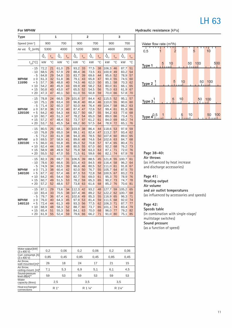
For MPHW Hydraulic resistance [kPa]
Page 38-40:Air throws(as influenced by heat increaseand discharge accessories)
Page 41:Heating outputAir volumeand air outlet temperatures(as influenced by accessories and speeds)
Page 42:Speeds table(in combination with single-stage/mulitstage switches)Sound pressure(as a function of speed)
QO ton QO ton QO ton QO ton QO ton QO ton
tLE[°C] kW °C kW °C kW °C kW °C kW °C kW °C
- 15 72,2 21 61,0 25 93,2 33 77,5 38 106,3 46 87,7 51- 10 68,5 25 57,9 29 88,4 36 73,5 41 100,9 49 83,2 54- 5 64,8 29 54,8 33 83,7 39 69,6 44 95,6 52 78,9 57
MPHW ± 0 61,3 32 51,8 36 79,1 43 65,8 47 90,3 55 74,5 60110/90 + 5 57,7 36 48,8 40 74,5 46 62,0 50 85,1 58 70,3 62
+ 10 54,2 40 45,9 43 69,9 49 58,2 53 80,0 61 66,1 65+ 15 50,8 43 43,0 47 65,5 52 54,5 56 75,0 63 61,9 67+ 20 47,3 47 40,1 50 61,0 55 50,8 59 70,0 66 57,8 70
- 15 78,8 24 66,5 29 101,6 37 84,4 42 115,5 52 95,1 57- 10 75,1 28 63,4 33 96,8 40 80,4 46 110,0 55 90,6 60- 5 71,4 32 60,3 37 92,0 44 76,4 49 104,7 58 86,2 63
MPHW ± 0 67,8 36 57,3 40 87,4 47 72,6 52 99,4 61 81,9 66120/100 + 5 64,2 40 54,3 44 82,7 50 68,7 55 94,2 63 77,6 68
+ 10 60,7 43 51,3 47 78,2 54 65,0 58 89,0 66 73,4 71+ 15 57,2 47 48,4 51 73,7 57 61,2 61 84,0 69 69,2 74+ 20 53,7 51 45,5 54 69,2 60 57,5 64 78,9 72 65,1 76
- 15 80,5 25 68,1 30 103,9 38 86,4 44 118,6 53 97,9 59- 10 76,8 29 65,0 34 99,1 41 82,4 47 113,2 57 93,4 62- 5 73,2 33 61,9 38 94,3 45 78,5 50 107,8 60 89,0 65
MPHW ± 0 69,5 37 58,9 41 89,6 48 74,6 54 102,6 63 84,7 68130/100 + 5 66,0 41 55,8 45 85,0 52 70,8 57 97,4 65 80,4 71
+ 10 62,4 44 52,9 48 80,5 55 67,0 60 92,2 68 76,2 73+ 15 58,9 48 49,9 52 75,9 58 63,3 63 87,1 71 72,0 76+ 20 55,5 52 47,0 55 71,5 61 59,6 66 82,1 74 67,9 78
- 15 82,3 26 69,7 31 106,5 39 88,5 45 121,8 55 100,7 61- 10 78,6 30 66,6 35 101,4 43 84,5 49 116,4 58 96,2 64- 5 74,9 34 63,5 39 96,6 46 80,5 52 111,0 61 91,8 67
MPHW ± 0 71,3 38 60,4 42 92,0 50 76,7 55 105,7 64 87,5 70140/100 + 5 67,7 42 57,4 46 87,3 53 72,8 58 100,5 67 83,2 73
+ 10 64,2 45 54,4 50 82,7 56 69,0 61 95,3 70 78,9 76+ 15 60,7 49 51,5 53 78,2 59 65,3 65 90,2 73 74,7 78+ 20 57,2 52 48,6 57 73,8 63 61,6 68 85,2 76 70,6 81
- 15 87,1 29 73,6 34 112,3 42 93,2 48 127,7 59 105,2 65- 10 83,4 33 70,5 38 107,4 46 89,2 52 122,2 62 100,7 68- 5 79,7 36 67,4 41 102,6 49 85,3 55 116,9 65 96,3 71
MPHW ± 0 76,0 40 64,3 45 97,9 53 81,4 59 111,5 68 92,0 74140/110 + 5 72,4 44 61,3 49 93,3 56 77,5 62 106,3 71 87,7 77
+ 10 68,9 48 58,3 52 88,7 60 73,7 65 101,1 74 83,4 79+ 15 65,4 51 55,3 56 84,1 63 70,0 68 96,0 77 79,2 82+ 20 61,9 55 52,4 59 79,6 66 66,2 71 91,0 80 75,1 85
12
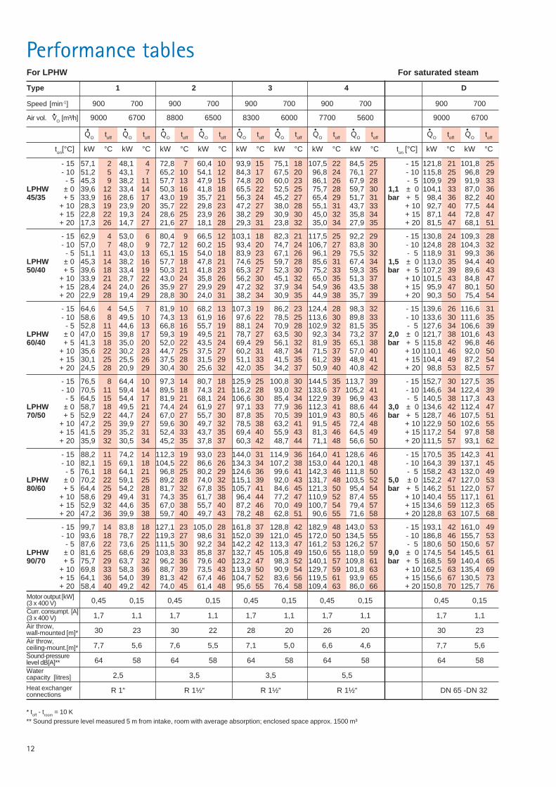
Performance tables
Speed [min-1] 900 700 900 700 900 700 900 700 900 700
Air vol. VO [m³/h] 9000 6700 8800 6500 8300 6000 7700 5600 9000 6700
Type 1 2 3 4 D
0,45 0,15 0,45 0,15 0,45 0,15 0,45 0,15 0,45 0,15
1,7 1,1 1,7 1,1 1,7 1,1 1,7 1,1 1,7 1,1
30 23 30 22 28 20 26 20 30 23
7,7 5,6 7,6 5,5 7,1 5,0 6,6 4,6 7,7 5,6
64 58 64 58 64 58 64 58 64 58
2,5 3,5 3,5 5,5
R 1“ R 1½“ R 1½“ R 1½“ DN 65 -DN 32
Motor output [kW](3 x 400 V)Curr. consumpt. [A](3 x 400 V)Air throw,wall-mounted [m]*Air throw,ceiling-mount.[m]*Sound-pressurelevel dB[A]**Watercapacity [litres]
For LPHW
* toff - troom = 10 K** Sound pressure level measured 5 m from intake, room with average absorption; enclosed space approx. 1500 m³
For saturated steam
Heat exchangerconnections
QO toff QO toff QO toff QO toff QO toff QO toff QO toff QO toff QO toff QO toff
ton[°C] kW °C kW °C kW °C kW °C kW °C kW °C kW °C kW °C ton [°C] kW °C kW °C
- 15 57,1 2 48,1 4 72,8 7 60,4 10 93,9 15 75,1 18 107,5 22 84,5 25 - 15 121,8 21 101,8 25- 10 51,2 5 43,1 7 65,2 10 54,1 12 84,3 17 67,5 20 96,8 24 76,1 27 - 10 115,8 25 96,8 29- 5 45,3 9 38,2 11 57,7 13 47,9 15 74,8 20 60,0 23 86,1 26 67,9 28 - 5 109,9 29 91,9 33
LPHW ± 0 39,6 12 33,4 14 50,3 16 41,8 18 65,5 22 52,5 25 75,7 28 59,7 30 1,1 ± 0 104,1 33 87,0 3645/35 + 5 33,9 16 28,6 17 43,0 19 35,7 21 56,3 24 45,2 27 65,4 29 51,7 31 bar + 5 98,4 36 82,2 40
+ 10 28,3 19 23,9 20 35,7 22 29,8 23 47,2 27 38,0 28 55,1 31 43,7 33 + 10 92,7 40 77,5 44+ 15 22,8 22 19,3 24 28,6 25 23,9 26 38,2 29 30,9 30 45,0 32 35,8 34 + 15 87,1 44 72,8 47+ 20 17,3 26 14,7 27 21,6 27 18,1 28 29,3 31 23,8 32 35,0 34 27,9 35 + 20 81,5 47 68,1 51
- 15 62,9 4 53,0 6 80,4 9 66,5 12 103,1 18 82,3 21 117,5 25 92,2 29 - 15 130,8 24 109,3 28- 10 57,0 7 48,0 9 72,7 12 60,2 15 93,4 20 74,7 24 106,7 27 83,8 30 - 10 124,8 28 104,3 32- 5 51,1 11 43,0 13 65,1 15 54,0 18 83,9 23 67,1 26 96,1 29 75,5 32 - 5 118,9 31 99,3 36
LPHW ± 0 45,3 14 38,2 16 57,7 18 47,8 21 74,6 25 59,7 28 85,6 31 67,4 34 1,5 ± 0 113,0 35 94,4 4050/40 + 5 39,6 18 33,4 19 50,3 21 41,8 23 65,3 27 52,3 30 75,2 33 59,3 35 bar + 5 107,2 39 89,6 43
+ 10 33,9 21 28,7 22 43,0 24 35,8 26 56,2 30 45,1 32 65,0 35 51,3 37 + 10 101,5 43 84,8 47+ 15 28,4 24 24,0 26 35,9 27 29,9 29 47,2 32 37,9 34 54,9 36 43,5 38 + 15 95,9 47 80,1 50+ 20 22,9 28 19,4 29 28,8 30 24,0 31 38,2 34 30,9 35 44,9 38 35,7 39 + 20 90,3 50 75,4 54
- 15 64,6 4 54,5 7 81,9 10 68,2 13 107,3 19 86,2 23 124,4 28 98,3 32 - 15 139,6 26 116,6 31- 10 58,6 8 49,5 10 74,3 13 61,9 16 97,6 22 78,5 25 113,6 30 89,8 33 - 10 133,6 30 111,6 35- 5 52,8 11 44,6 13 66,8 16 55,7 19 88,1 24 70,9 28 102,9 32 81,5 35 - 5 127,6 34 106,6 39
LPHW ± 0 47,0 15 39,8 17 59,3 19 49,5 21 78,7 27 63,5 30 92,3 34 73,2 37 2,0 ± 0 121,7 38 101,6 4360/40 + 5 41,3 18 35,0 20 52,0 22 43,5 24 69,4 29 56,1 32 81,9 35 65,1 38 bar + 5 115,8 42 96,8 46
+ 10 35,6 22 30,2 23 44,7 25 37,5 27 60,2 31 48,7 34 71,5 37 57,0 40 + 10 110,1 46 92,0 50+ 15 30,1 25 25,5 26 37,5 28 31,5 29 51,1 33 41,5 35 61,2 39 48,9 41 + 15 104,4 49 87,2 54+ 20 24,5 28 20,9 29 30,4 30 25,6 32 42,0 35 34,2 37 50,9 40 40,8 42 + 20 98,8 53 82,5 57
- 15 76,5 8 64,4 10 97,3 14 80,7 18 125,9 25 100,8 30 144,5 35 113,7 39 - 15 152,7 30 127,5 35- 10 70,5 11 59,4 14 89,5 18 74,3 21 116,2 28 93,0 32 133,6 37 105,2 41 - 10 146,6 34 122,4 39- 5 64,5 15 54,4 17 81,9 21 68,1 24 106,6 30 85,4 34 122,9 39 96,9 43 - 5 140,5 38 117,3 43
LPHW ± 0 58,7 18 49,5 21 74,4 24 61,9 27 97,1 33 77,9 36 112,3 41 88,6 44 3,0 ± 0 134,6 42 112,4 4770/50 + 5 52,9 22 44,7 24 67,0 27 55,7 30 87,8 35 70,5 39 101,9 43 80,5 46 bar + 5 128,7 46 107,5 51
+ 10 47,2 25 39,9 27 59,6 30 49,7 32 78,5 38 63,2 41 91,5 45 72,4 48 + 10 122,9 50 102,6 55+ 15 41,5 29 35,2 31 52,4 33 43,7 35 69,4 40 55,9 43 81,3 46 64,5 49 + 15 117,2 54 97,8 58+ 20 35,9 32 30,5 34 45,2 35 37,8 37 60,3 42 48,7 44 71,1 48 56,6 50 + 20 111,5 57 93,1 62
- 15 88,2 11 74,2 14 112,3 19 93,0 23 144,0 31 114,9 36 164,0 41 128,6 46 - 15 170,5 35 142,3 41- 10 82,1 15 69,1 18 104,5 22 86,6 26 134,3 34 107,2 38 153,0 44 120,1 48 - 10 164,3 39 137,1 45- 5 76,1 18 64,1 21 96,8 25 80,2 29 124,6 36 99,6 41 142,3 46 111,8 50 - 5 158,2 43 132,0 49
LPHW ± 0 70,2 22 59,1 25 89,2 28 74,0 32 115,1 39 92,0 43 131,7 48 103,5 52 5,0 ± 0 152,2 47 127,0 5380/60 + 5 64,4 25 54,2 28 81,7 32 67,8 35 105,7 41 84,6 45 121,3 50 95,4 54 bar + 5 146,2 51 122,0 57
+ 10 58,6 29 49,4 31 74,3 35 61,7 38 96,4 44 77,2 47 110,9 52 87,4 55 + 10 140,4 55 117,1 61+ 15 52,9 32 44,6 35 67,0 38 55,7 40 87,2 46 70,0 49 100,7 54 79,4 57 + 15 134,6 59 112,3 65+ 20 47,2 36 39,9 38 59,7 40 49,7 43 78,2 48 62,8 51 90,6 55 71,6 58 + 20 128,8 63 107,5 68
- 15 99,7 14 83,8 18 127,1 23 105,0 28 161,8 37 128,8 42 182,9 48 143,0 53 - 15 193,1 42 161,0 49- 10 93,6 18 78,7 22 119,3 27 98,6 31 152,0 39 121,0 45 172,0 50 134,5 55 - 10 186,8 46 155,7 53- 5 87,6 22 73,6 25 111,5 30 92,2 34 142,2 42 113,3 47 161,2 53 126,2 57 - 5 180,6 50 150,6 57
LPHW ± 0 81,6 25 68,6 29 103,8 33 85,8 37 132,7 45 105,8 49 150,6 55 118,0 59 9,0 ± 0 174,5 54 145,5 6190/70 + 5 75,7 29 63,7 32 96,2 36 79,6 40 123,2 47 98,3 52 140,1 57 109,8 61 bar + 5 168,5 59 140,4 65
+ 10 69,8 33 58,3 36 88,7 39 73,5 43 113,9 50 90,9 54 129,7 59 101,8 63 + 10 162,5 63 135,4 69+ 15 64,1 36 54,0 39 81,3 42 67,4 46 104,7 52 83,6 56 119,5 61 93,9 65 + 15 156,6 67 130,5 73+ 20 58,4 40 49,2 42 74,0 45 61,4 48 95,6 55 76,4 58 109,4 63 86,0 66 + 20 150,8 70 125,7 76
13
LH 100
Type 1 2 3
Speed [min-1] 900 700 900 700 900 700
Air vol. VO [m³/h] 9000 6700 8800 6500 8300 6000
Motor output [kW](3 x 400 V)Curr. consumpt. [A](3 x 400 V)Air throw,wall-mounted [m]*Air throw,ceiling-mount. [m]*Sound-pressurelevel dB[A]**Watercapacity [litres]
Heat exchangerconnections
0,45 0,15 0,45 0,15 0,45 0,15
1,7 1,1 1,7 1,1 1,7 1,1
30 23 30 22 28 20
7,7 5,6 7,6 5,5 7,1 5,0
64 58 64 58 64 58
3,5 5,5 7,5
R 1“ R 1½“ R 1½“
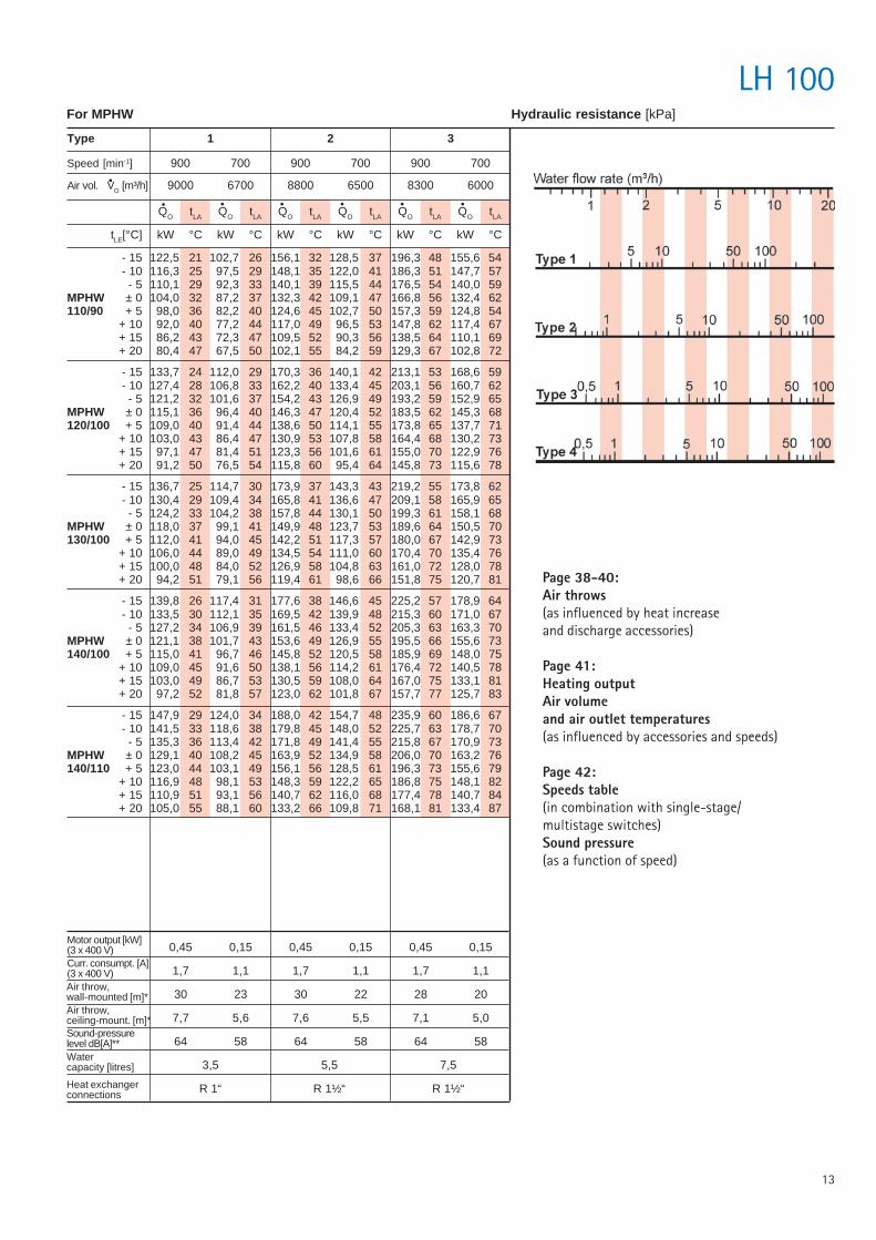
For MPHW Hydraulic resistance [kPa]
Page 38-40:Air throws(as influenced by heat increaseand discharge accessories)
Page 41:Heating outputAir volumeand air outlet temperatures(as influenced by accessories and speeds)
Page 42:Speeds table(in combination with single-stage/multistage switches)Sound pressure(as a function of speed)
QO tLA QO tLA QO tLA QO tLA QO tLA QO tLA
tLE[°C] kW °C kW °C kW °C kW °C kW °C kW °C
- 15 122,5 21 102,7 26 156,1 32 128,5 37 196,3 48 155,6 54- 10 116,3 25 97,5 29 148,1 35 122,0 41 186,3 51 147,7 57- 5 110,1 29 92,3 33 140,1 39 115,5 44 176,5 54 140,0 59
MPHW ± 0 104,0 32 87,2 37 132,3 42 109,1 47 166,8 56 132,4 62110/90 + 5 98,0 36 82,2 40 124,6 45 102,7 50 157,3 59 124,8 54
+ 10 92,0 40 77,2 44 117,0 49 96,5 53 147,8 62 117,4 67+ 15 86,2 43 72,3 47 109,5 52 90,3 56 138,5 64 110,1 69+ 20 80,4 47 67,5 50 102,1 55 84,2 59 129,3 67 102,8 72
- 15 133,7 24 112,0 29 170,3 36 140,1 42 213,1 53 168,6 59- 10 127,4 28 106,8 33 162,2 40 133,4 45 203,1 56 160,7 62- 5 121,2 32 101,6 37 154,2 43 126,9 49 193,2 59 152,9 65
MPHW ± 0 115,1 36 96,4 40 146,3 47 120,4 52 183,5 62 145,3 68120/100 + 5 109,0 40 91,4 44 138,6 50 114,1 55 173,8 65 137,7 71
+ 10 103,0 43 86,4 47 130,9 53 107,8 58 164,4 68 130,2 73+ 15 97,1 47 81,4 51 123,3 56 101,6 61 155,0 70 122,9 76+ 20 91,2 50 76,5 54 115,8 60 95,4 64 145,8 73 115,6 78
- 15 136,7 25 114,7 30 173,9 37 143,3 43 219,2 55 173,8 62- 10 130,4 29 109,4 34 165,8 41 136,6 47 209,1 58 165,9 65- 5 124,2 33 104,2 38 157,8 44 130,1 50 199,3 61 158,1 68
MPHW ± 0 118,0 37 99,1 41 149,9 48 123,7 53 189,6 64 150,5 70130/100 + 5 112,0 41 94,0 45 142,2 51 117,3 57 180,0 67 142,9 73
+ 10 106,0 44 89,0 49 134,5 54 111,0 60 170,4 70 135,4 76+ 15 100,0 48 84,0 52 126,9 58 104,8 63 161,0 72 128,0 78+ 20 94,2 51 79,1 56 119,4 61 98,6 66 151,8 75 120,7 81
- 15 139,8 26 117,4 31 177,6 38 146,6 45 225,2 57 178,9 64- 10 133,5 30 112,1 35 169,5 42 139,9 48 215,3 60 171,0 67- 5 127,2 34 106,9 39 161,5 46 133,4 52 205,3 63 163,3 70
MPHW ± 0 121,1 38 101,7 43 153,6 49 126,9 55 195,5 66 155,6 73140/100 + 5 115,0 41 96,7 46 145,8 52 120,5 58 185,9 69 148,0 75
+ 10 109,0 45 91,6 50 138,1 56 114,2 61 176,4 72 140,5 78+ 15 103,0 49 86,7 53 130,5 59 108,0 64 167,0 75 133,1 81+ 20 97,2 52 81,8 57 123,0 62 101,8 67 157,7 77 125,7 83
- 15 147,9 29 124,0 34 188,0 42 154,7 48 235,9 60 186,6 67- 10 141,5 33 118,6 38 179,8 45 148,0 52 225,7 63 178,7 70- 5 135,3 36 113,4 42 171,8 49 141,4 55 215,8 67 170,9 73
MPHW ± 0 129,1 40 108,2 45 163,9 52 134,9 58 206,0 70 163,2 76140/110 + 5 123,0 44 103,1 49 156,1 56 128,5 61 196,3 73 155,6 79
+ 10 116,9 48 98,1 53 148,3 59 122,2 65 186,8 75 148,1 82+ 15 110,9 51 93,1 56 140,7 62 116,0 68 177,4 78 140,7 84+ 20 105,0 55 88,1 60 133,2 66 109,8 71 168,1 81 133,4 87
14
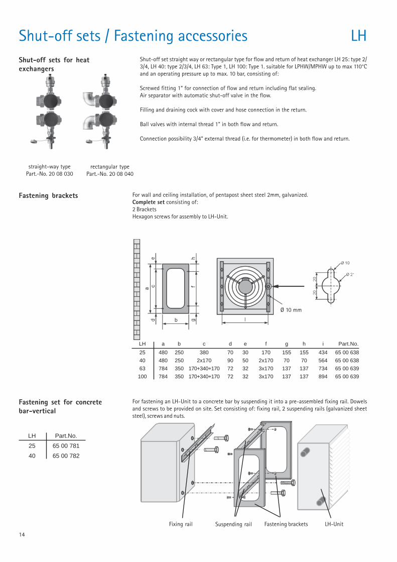
Shut-off sets / Fastening accessories LHShut-off sets for heatexchangers
Shut-off set straight way or rectangular type for flow and return of heat exchanger LH 25: type 2/3/4, LH 40: type 2/3/4, LH 63: Type 1, LH 100: Type 1. suitable for LPHW/MPHW up to max 110°Cand an operating pressure up to max. 10 bar, consisting of:
Screwed fitting 1“ for connection of flow and return including flat sealing.Air separator with automatic shut-off valve in the flow.
Filling and draining cock with cover and hose connection in the return.
Ball valves with internal thread 1“ in both flow and return.
Connection possibility 3/4“ external thread (i.e. for thermometer) in both flow and return.
straight-way typePart.-No. 20 08 030
rectangular typePart.-No. 20 08 040
Fastening brackets For wall and ceiling installation, of pentapost sheet steel 2mm, galvanized.Complete set consisting of:2 BracketsHexagon screws for assembly to LH-Unit.
LH a b c d e f g h i Part.No.
25 480 250 380 70 30 170 155 155 434 65 00 638
40 480 250 2x170 90 50 2x170 70 70 564 65 00 638
63 784 350 170+340+170 72 32 3x170 137 137 734 65 00 639
100 784 350 170+340+170 72 32 3x170 137 137 894 65 00 639
Fastening set for concretebar-vertical
For fastening an LH-Unit to a concrete bar by suspending it into a pre-assembled fixing rail. Dowelsand screws to be provided on site. Set consisting of: fixing rail, 2 suspending rails (galvanized sheetsteel), screws and nuts.
LH Part.No.
25 65 00 781
40 65 00 782
Fixing rail Suspending rail Fastening brackets LH-Unit
Ø 10 mm
15
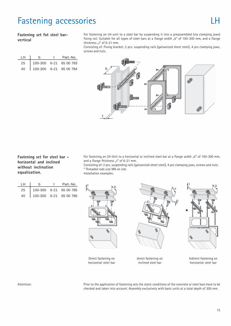
Fastening set fot steel bar-vertical
For fastening an LH-unit to a steel bar by suspending it into a preassembled (via clamping jaws)fixing rail. Suitable for all types of steel bars at a flange width „b“ of 100-300 mm, and a flangethickness „t“ of 6-21 mm.Consisting of: Fixing bracket, 2 pcs. suspending rails (galvanized sheet steel), 4 pcs clamping jaws,screws and nuts.
LH b t Part.-No.
25 100-300 6-21 65 00 783
40 100-300 6-21 65 00 784
Fastening accessories LH
Fastening set for steel bar -horizontal and inclinedwithout inclinationequalization.
LH b t Part.-No.
25 100-300 6-21 65 00 785
40 100-300 6-21 65 00 786
For fastening an LH-Unit to a horizontal or inclined steel bar at a flange width „b“ of 100-300 mm,and a flange fhickness „t“ of 6-21 mm.Consisting of: 2 pcs. suspending rails (galvanized sheet steel), 4 pcs clamping jaws, screws and nuts.* Threaded rods size M8 on site.Installation examples:
Direct fastening onhorizontal steel bar
direct fastening oninclined steel bar
Indirect fastening onhorizontal steel bar
*
Attention: Prior to the application of fastening sets the static conditions of the concrete or steel bars have to bechecked and taken into account. Assembly exclusively with basic units at a total depth of 300 mm.
16
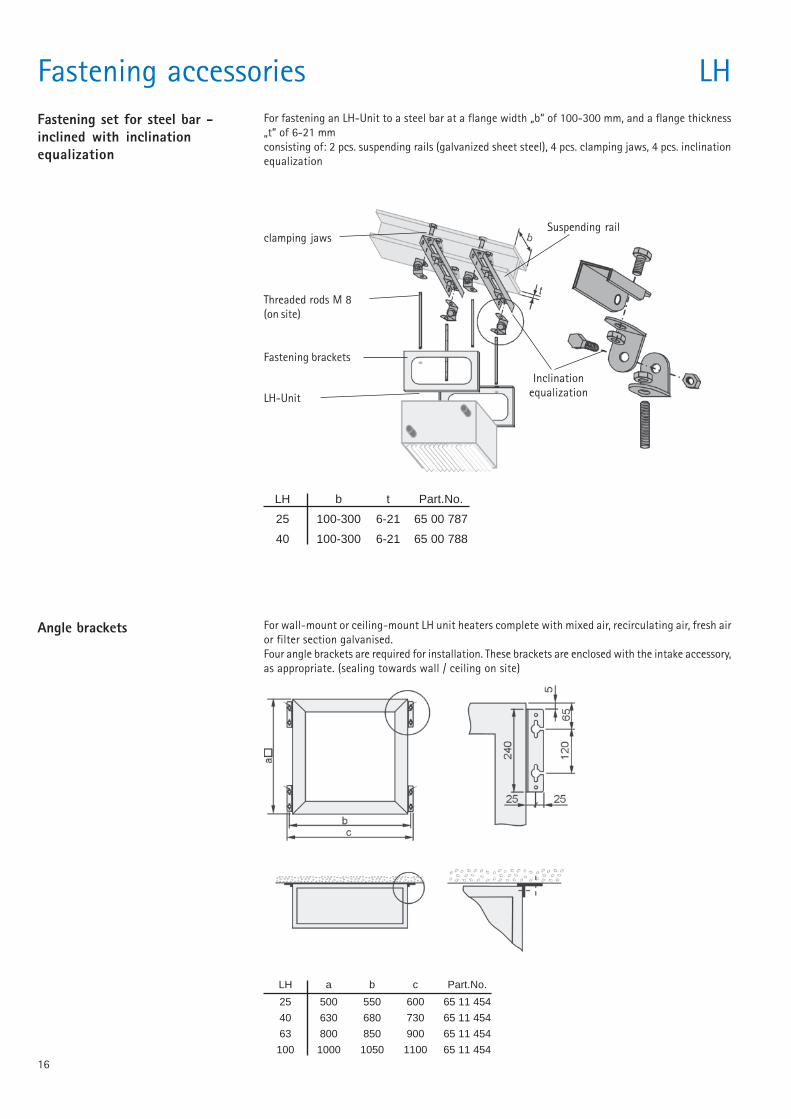
Fastening accessories LHFastening set for steel bar -inclined with inclinationequalization
For fastening an LH-Unit to a steel bar at a flange width „b“ of 100-300 mm, and a flange thickness„t“ of 6-21 mmconsisting of: 2 pcs. suspending rails (galvanized sheet steel), 4 pcs. clamping jaws, 4 pcs. inclinationequalization
LH b t Part.No.
25 100-300 6-21 65 00 787
40 100-300 6-21 65 00 788
Suspending rail
Fastening brackets
LH-Unit
Inclinationequalization
clamping jaws
Threaded rods M 8(on site)
For wall-mount or ceiling-mount LH unit heaters complete with mixed air, recirculating air, fresh airor filter section galvanised.Four angle brackets are required for installation. These brackets are enclosed with the intake accessory,as appropriate. (sealing towards wall / ceiling on site)
Angle brackets
LH a b c Part.No.
25 500 550 600 65 11 454
40 630 680 730 65 11 454
63 800 850 900 65 11 454
100 1000 1050 1100 65 11 454
17
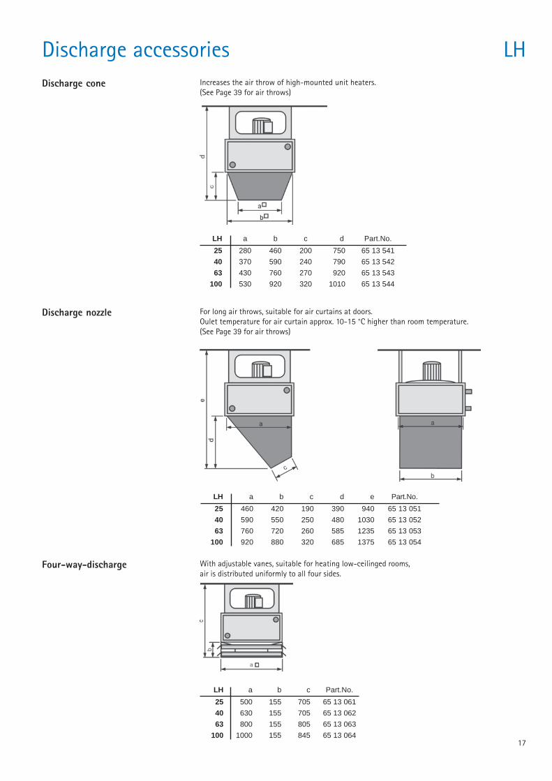
Discharge accessories LHDischarge cone Increases the air throw of high-mounted unit heaters.
(See Page 39 for air throws)
LH a b c d Part.No.
25 280 460 200 750 65 13 541
40 370 590 240 790 65 13 542
63 430 760 270 920 65 13 543
100 530 920 320 1010 65 13 544
Discharge nozzle For long air throws, suitable for air curtains at doors.Oulet temperature for air curtain approx. 10-15 °C higher than room temperature.(See Page 39 for air throws)
LH a b c d e Part.No.
25 460 420 190 390 940 65 13 051
40 590 550 250 480 1030 65 13 052
63 760 720 260 585 1235 65 13 053
100 920 880 320 685 1375 65 13 054
Four-way-discharge With adjustable vanes, suitable for heating low-ceilinged rooms,air is distributed uniformly to all four sides.
LH a b c Part.No.
25 500 155 705 65 13 061
40 630 155 705 65 13 062
63 800 155 805 65 13 063
100 1000 155 845 65 13 064
18
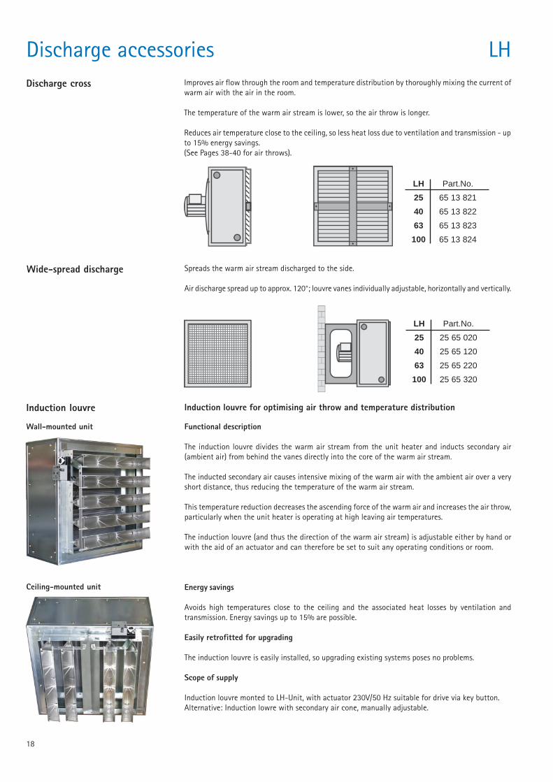
Discharge accessories LHDischarge cross Improves air flow through the room and temperature distribution by thoroughly mixing the current of
warm air with the air in the room.
The temperature of the warm air stream is lower, so the air throw is longer.
Reduces air temperature close to the ceiling, so less heat loss due to ventilation and transmission - upto 15% energy savings.(See Pages 38-40 for air throws).
LH Part.No.
25 65 13 821
40 65 13 822
63 65 13 823
100 65 13 824
Wide-spread discharge Spreads the warm air stream discharged to the side.
Air discharge spread up to approx. 120°; louvre vanes individually adjustable, horizontally and vertically.
LH Part.No.
25 25 65 020
40 25 65 120
63 25 65 220
100 25 65 320
Induction louvre for optimising air throw and temperature distribution
Functional description
The induction louvre divides the warm air stream from the unit heater and inducts secondary air(ambient air) from behind the vanes directly into the core of the warm air stream.
The inducted secondary air causes intensive mixing of the warm air with the ambient air over a veryshort distance, thus reducing the temperature of the warm air stream.
This temperature reduction decreases the ascending force of the warm air and increases the air throw,particularly when the unit heater is operating at high leaving air temperatures.
The induction louvre (and thus the direction of the warm air stream) is adjustable either by hand orwith the aid of an actuator and can therefore be set to suit any operating conditions or room.
Energy savings
Avoids high temperatures close to the ceiling and the associated heat losses by ventilation andtransmission. Energy savings up to 15% are possible.
Easily retrofitted for upgrading
The induction louvre is easily installed, so upgrading existing systems poses no problems.
Scope of supply
Induction louvre monted to LH-Unit, with actuator 230V/50 Hz suitable for drive via key button.Alternative: Induction lowre with secondary air cone, manually adjustable.
Wall-mounted unit
Ceiling-mounted unit
Induction louvre
19
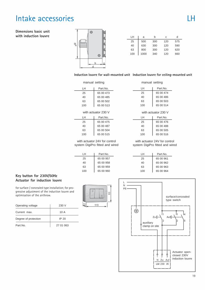
Induction louvre for ceiling-mounted unit
manual setting
Induction louvre for wall-mounted unit
manual setting
LH Part.No.
25 65 00 473
40 65 00 485
63 65 00 502
100 65 00 513
LH Part.No.
25 65 00 475
40 65 00 487
63 65 00 504
100 65 00 515
with actuator 230 V
LH Part.No.
25 65 00 474
40 65 00 486
63 65 00 503
100 65 00 514
LH Part.No.
25 65 00 476
40 65 00 488
63 65 00 505
100 65 00 516
with actuator 230 V
LH Part.No.
25 65 00 957
40 65 00 958
63 65 00 959
100 65 00 960
with actuator 24V for controlsystem DigiPro fitted and wired
LH Part.No.
25 65 00 961
40 65 00 962
63 65 00 963
100 65 00 964
with actuator 24V for controlsystem DigiPro fitted and wired
Intake accessories LH
LH a b c d
25 500 300 120 575
40 630 300 120 590
63 800 300 120 620
100 1000 340 120 660
Dimensions basic unitwith induction louvre
Key button for 230V/50HzActuator for induction louvre
for surface / concealed type installation; for pro-gressive adjustment of the induction louvre andoptimisation of the airthrow.
Actuator open-closed 230Vinduction louvre
surface/concealedtype switch
Operating voltage 230 V
Current max. 10 A
Degree of protection IP 20
Part.No. 27 01 063auxiliaryclamp on site
20
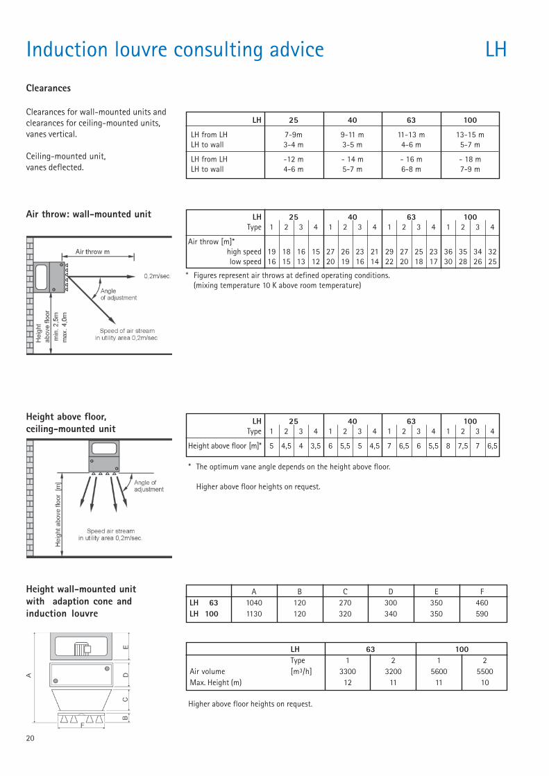
LH 63 100Type 1 2 1 2
Air volume [m³/h] 3300 3200 5600 5500Max. Height (m) 12 11 11 10
LH 25 40 63 100
LH from LH 7-9m 9-11 m 11-13 m 13-15 mLH to wall 3-4 m 3-5 m 4-6 m 5-7 m
LH from LH -12 m - 14 m - 16 m - 18 mLH to wall 4-6 m 5-7 m 6-8 m 7-9 m
Induction louvre consulting advice LH
Air throw: wall-mounted unit
Height above floor,ceiling-mounted unit
LH 25 40 63 100Type 1 2 3 4 1 2 3 4 1 2 3 4 1 2 3 4
Air throw [m]*high speed 19 18 16 15 27 26 23 21 29 27 25 23 36 35 34 32low speed 16 15 13 12 20 19 16 14 22 20 18 17 30 28 26 25
LH 25 40 63 100Type 1 2 3 4 1 2 3 4 1 2 3 4 1 2 3 4
Height above floor [m]* 5 4,5 4 3,5 6 5,5 5 4,5 7 6,5 6 5,5 8 7,5 7 6,5
* Figures represent air throws at defined operating conditions.(mixing temperature 10 K above room temperature)
* The optimum vane angle depends on the height above floor.
Higher above floor heights on request.
Clearances
Clearances for wall-mounted units andclearances for ceiling-mounted units,vanes vertical.
Ceiling-mounted unit,vanes deflected.
Height wall-mounted unitwith adaption cone andinduction louvre
A B C D E FLH 63 1040 120 270 300 350 460LH 100 1130 120 320 340 350 590
Higher above floor heights on request.
21
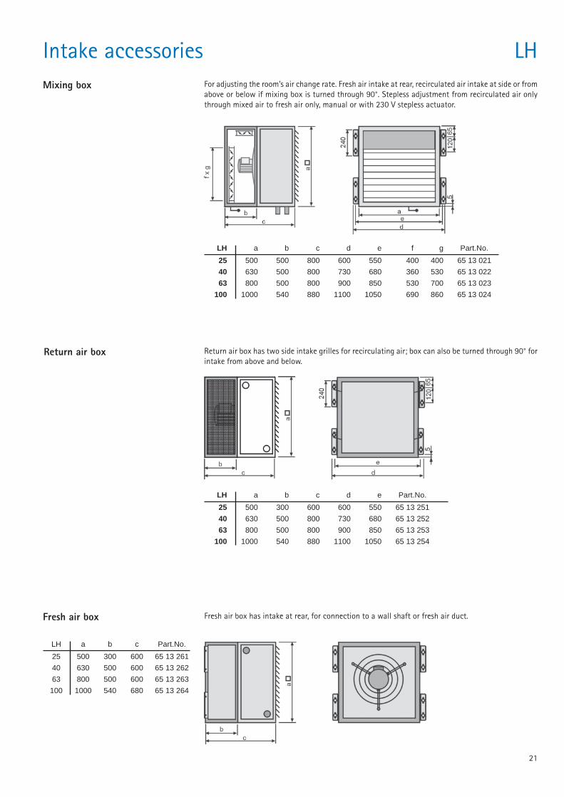
Intake accessories LHMixing box For adjusting the room’s air change rate. Fresh air intake at rear, recirculated air intake at side or from
above or below if mixing box is turned through 90°. Stepless adjustment from recirculated air onlythrough mixed air to fresh air only, manual or with 230 V stepless actuator.
LH a b c d e f g Part.No.
25 500 500 800 600 550 400 400 65 13 021
40 630 500 800 730 680 360 530 65 13 022
63 800 500 800 900 850 530 700 65 13 023
100 1000 540 880 1100 1050 690 860 65 13 024
Return air box Return air box has two side intake grilles for recirculating air; box can also be turned through 90° forintake from above and below.
LH a b c d e Part.No.
25 500 300 600 600 550 65 13 251
40 630 500 800 730 680 65 13 252
63 800 500 800 900 850 65 13 253
100 1000 540 880 1100 1050 65 13 254
Fresh air box Fresh air box has intake at rear, for connection to a wall shaft or fresh air duct.
LH a b c Part.No.
25 500 300 600 65 13 261
40 630 500 600 65 13 262
63 800 500 600 65 13 263
100 1000 540 680 65 13 264
22
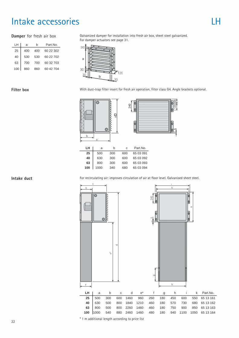
Damper for fresh air box
LH a b Part.No.
25 400 400 60 22 302
40 530 530 60 22 702
63 700 700 60 32 703
100 860 860 60 42 704
Galvanized damper for installation into fresh air box, sheet steel galvanized.For damper actuators see page 31.
Intake accessories LH
Filter box With dust-trap filter insert for fresh air operation, filter class G4. Angle brackets optional.
LH a b c Part.No.
25 500 300 600 65 03 091
40 630 300 600 65 03 092
63 800 300 600 65 03 093
100 1000 340 680 65 03 094
Intake duct For recirculating air: improves circulation of air at floor level. Galvanised sheet steel.
LH a b c d e* f g h i k Part.No.
25 500 300 600 1460 960 260 180 450 600 550 65 13 161
40 630 500 800 1840 1210 460 180 570 730 680 65 13 162
63 800 500 800 2260 1460 460 180 750 900 850 65 13 163
100 1000 540 880 2460 1460 480 180 940 1100 1050 65 13 164
* 1 m additional length according to price list
23
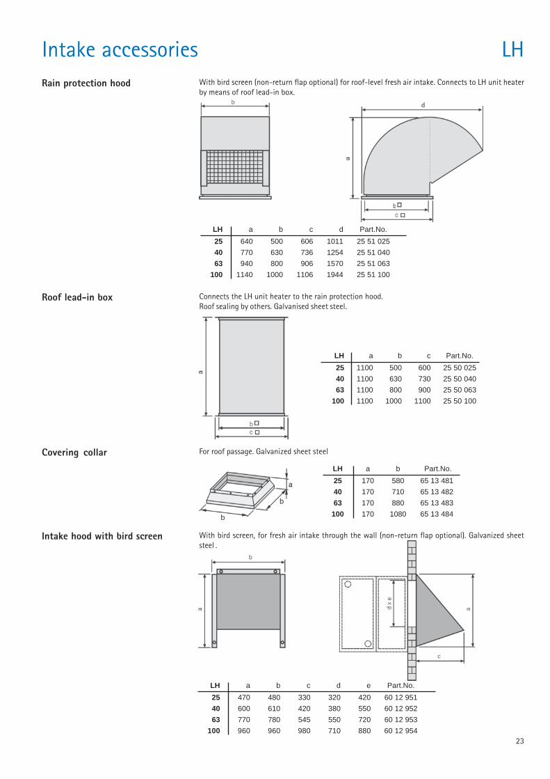
Intake accessories LHRain protection hood With bird screen (non-return flap optional) for roof-level fresh air intake. Connects to LH unit heater
by means of roof lead-in box.
LH a b c d Part.No.
25 640 500 606 1011 25 51 025
40 770 630 736 1254 25 51 040
63 940 800 906 1570 25 51 063
100 1140 1000 1106 1944 25 51 100
Roof lead-in box Connects the LH unit heater to the rain protection hood.Roof sealing by others. Galvanised sheet steel.
Covering collar For roof passage. Galvanized sheet steel
LH a b Part.No.
25 170 580 65 13 481
40 170 710 65 13 482
63 170 880 65 13 483
100 170 1080 65 13 484
Intake hood with bird screen
LH a b c Part.No.
25 1100 500 600 25 50 025
40 1100 630 730 25 50 040
63 1100 800 900 25 50 063
100 1100 1000 1100 25 50 100
LH a b c d e Part.No.
25 470 480 330 320 420 60 12 951
40 600 610 420 380 550 60 12 952
63 770 780 545 550 720 60 12 953
100 960 960 980 710 880 60 12 954
With bird screen, for fresh air intake through the wall (non-return flap optional). Galvanized sheetsteel .
24
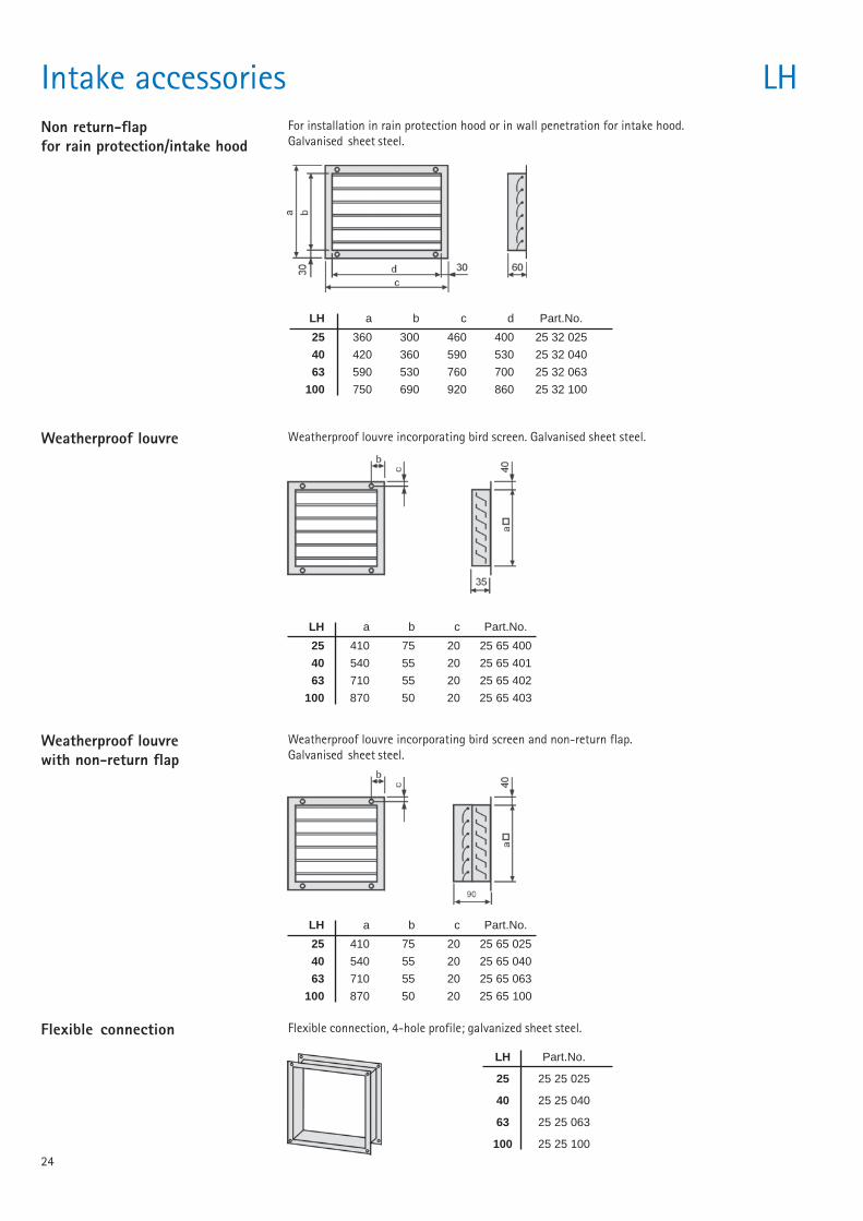
Intake accessories LHNon return-flapfor rain protection/intake hood
For installation in rain protection hood or in wall penetration for intake hood.Galvanised sheet steel.
LH a b c d Part.No.
25 360 300 460 400 25 32 025
40 420 360 590 530 25 32 040
63 590 530 760 700 25 32 063
100 750 690 920 860 25 32 100
Weatherproof louvre Weatherproof louvre incorporating bird screen. Galvanised sheet steel.
LH a b c Part.No.
25 410 75 20 25 65 400
40 540 55 20 25 65 401
63 710 55 20 25 65 402
100 870 50 20 25 65 403
Weatherproof louvrewith non-return flap
Weatherproof louvre incorporating bird screen and non-return flap.Galvanised sheet steel.
LH a b c Part.No.
25 410 75 20 25 65 025
40 540 55 20 25 65 040
63 710 55 20 25 65 063
100 870 50 20 25 65 100
Flexible connection Flexible connection, 4-hole profile; galvanized sheet steel.
LH Part.No.
25 25 25 025
40 25 25 040
63 25 25 063
100 25 25 100
25
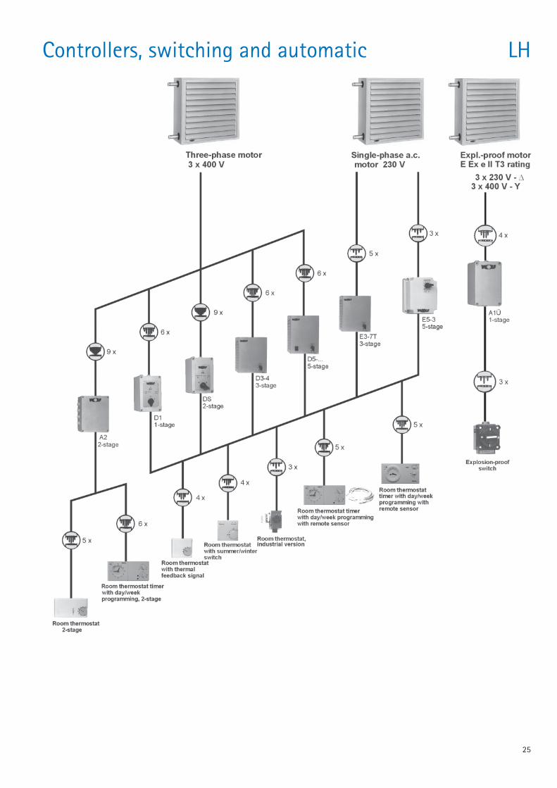
Controllers, switching and automatic LH
26
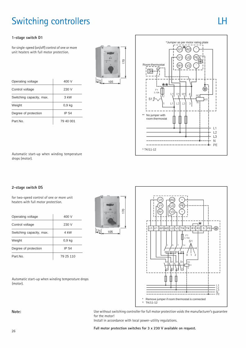
Operating voltage 400 V
Control voltage 230 V
Switching capacity, max. 3 kW
Weight 0,9 kg
Degree of protection IP 54
Part.No. 79 40 001
1-stage switch D1
for single-speed (on/off) control of one or moreunit heaters with full motor protection.
Switching controllers
2-stage switch DS
for two-speed control of one or more unitheaters with full motor protection.
Note: Use without switching controller for full motor protection voids the manufacturer’s guaranteefor the motor!Install in accordance with local power-utility regulations.
Full motor protection switches for 3 x 230 V available on request.
Automatic start-up when winding temperaturedrops (motor).
Automatic start-up when winding temperature drops(motor).
Operating voltage 400 V
Control voltage 230 V
Switching capacity, max. 4 kW
Weight 0,9 kg
Degree of protection IP 54
Part.No. 79 25 110
*Jumper as per motor rating plate
Room thermostat
** No jumper withroom thermostat
* Remove jumper if room thermostat is connected1) TK/11-12
LH
1) TK/11-12
27
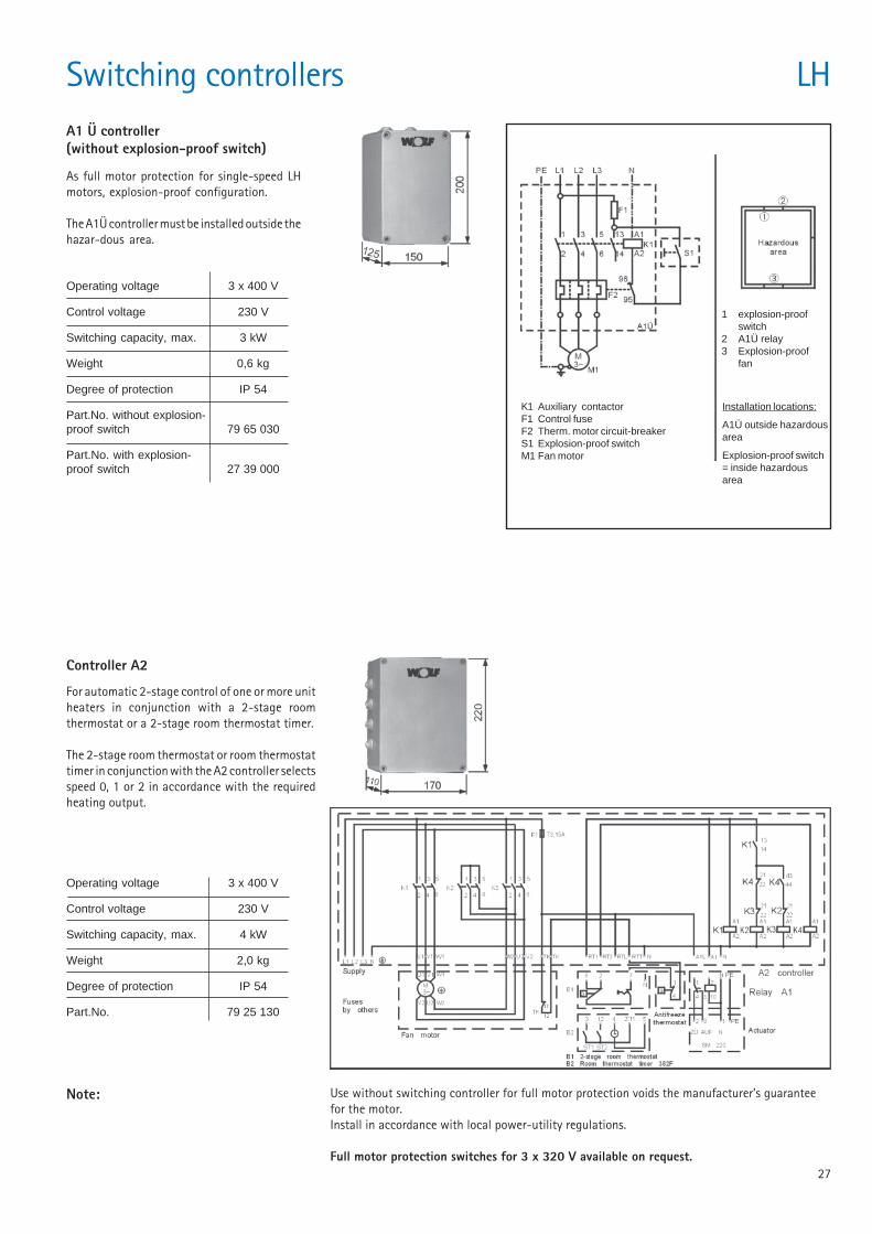
Operating voltage 3 x 400 V
Control voltage 230 V
Switching capacity, max. 4 kW
Weight 2,0 kg
Degree of protection IP 54
Part.No. 79 25 130
Operating voltage 3 x 400 V
Control voltage 230 V
Switching capacity, max. 3 kW
Weight 0,6 kg
Degree of protection IP 54
Part.No. without explosion-proof switch 79 65 030
Part.No. with explosion-proof switch 27 39 000
Switching controllers LHA1 Ü controller(without explosion-proof switch)
As full motor protection for single-speed LHmotors, explosion-proof configuration.
The A1Ü controller must be installed outside thehazar-dous area.
K1 Auxiliary contactorF1 Control fuseF2 Therm. motor circuit-breakerS1 Explosion-proof switchM1 Fan motor
1 explosion-proofswitch
2 A1Ü relay3 Explosion-proof
fan
Installation locations:
A1Ü outside hazardousarea
Explosion-proof switch= inside hazardousarea
Controller A2
For automatic 2-stage control of one or more unitheaters in conjunction with a 2-stage roomthermostat or a 2-stage room thermostat timer.
The 2-stage room thermostat or room thermostattimer in conjunction with the A2 controller selectsspeed 0, 1 or 2 in accordance with the requiredheating output.
Note: Use without switching controller for full motor protection voids the manufacturer’s guaranteefor the motor.Install in accordance with local power-utility regulations.
Full motor protection switches for 3 x 320 V available on request.
28
Switching controllers LH
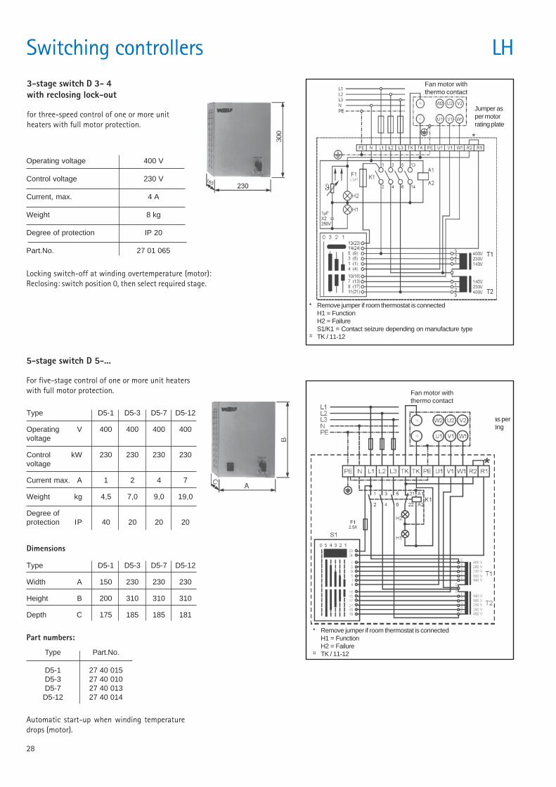
5-stage switch D 5-...
For five-stage control of one or more unit heaterswith full motor protection.
Automatic start-up when winding temperaturedrops (motor).
Dimensions
Type D5-1 D5-3 D5-7 D5-12
Width A 150 230 230 230
Height B 200 310 310 310
Depth C 175 185 185 181
Type Part.No.
D5-1 27 40 015D5-3 27 40 010D5-7 27 40 013D5-12 27 40 014
Part numbers:
Type D5-1 D5-3 D5-7 D5-12
Operating V 400 400 400 400voltage
Control kW 230 230 230 230voltage
Current max. A 1 2 4 7
Weight kg 4,5 7,0 9,0 19,0
Degree ofprotection IP 40 20 20 20
Fan motor withthermo contact
Jumper as permotor ratingplate
* Remove jumper if room thermostat is connectedH1 = FunctionH2 = Failure
1) TK / 11-12
3-stage switch D 3- 4with reclosing lock-out
for three-speed control of one or more unitheaters with full motor protection.
Locking switch-off at winding overtemperature (motor):Reclosing: switch position 0, then select required stage.
Operating voltage 400 V
Control voltage 230 V
Current, max. 4 A
Weight 8 kg
Degree of protection IP 20
Part.No. 27 01 065
Fan motor withthermo contact
Jumper asper motorrating plate
* Remove jumper if room thermostat is connectedH1 = FunctionH2 = FailureS1/K1 = Contact seizure depending on manufacture type
1) TK / 11-12
29
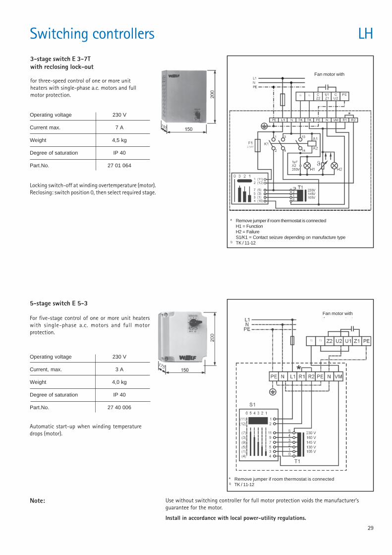
3-stage switch E 3-7Twith reclosing lock-out
for three-speed control of one or more unitheaters with single-phase a.c. motors and fullmotor protection.
Locking switch-off at winding overtemperature (motor).Reclosing: switch position 0, then select required stage.
Operating voltage 230 V
Current max. 7 A
Weight 4,5 kg
Degree of saturation IP 40
Part.No. 27 01 064
* Remove jumper if room thermostat is connectedH1 = FunctionH2 = FailureS1/K1 = Contact seizure depending on manufacture type
1) TK / 11-12
Fan motor withthermo contact
Switching controllers LH
Note:
5-stage switch E 5-3
For five-stage control of one or more unit heaterswith single-phase a.c. motors and full motorprotection.
Automatic start-up when winding temperaturedrops (motor).
Operating voltage 230 V
Current, max. 3 A
Weight 4,0 kg
Degree of saturation IP 40
Part.No. 27 40 006
Use without switching controller for full motor protection voids the manufacturer’sguarantee for the motor.
Install in accordance with local power-utility regulations.
* Remove jumper if room thermostat is connected1) TK / 11-12
Fan motor withthermo contacts
30
Actuators for fresh air or mixed air LH
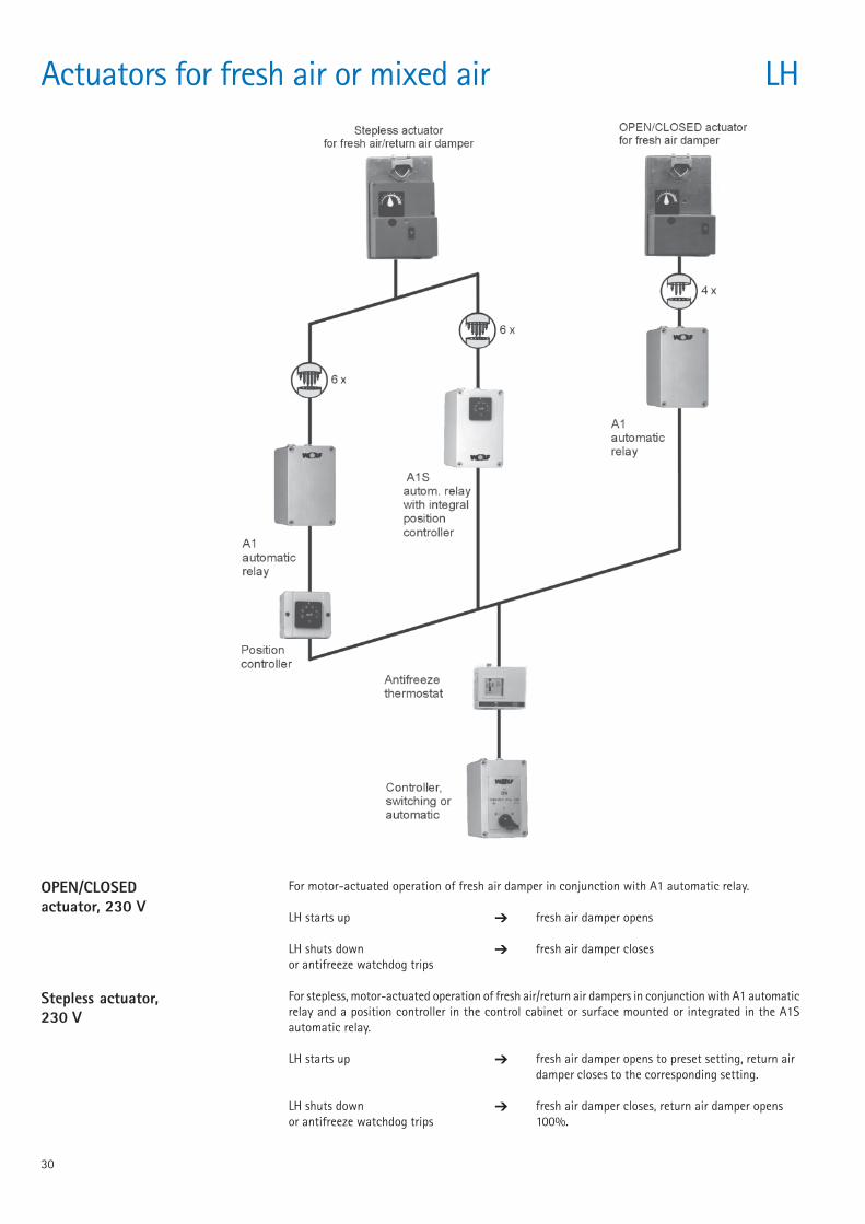
OPEN/CLOSEDactuator, 230 V
For motor-actuated operation of fresh air damper in conjunction with A1 automatic relay.
LH starts up ➔ fresh air damper opens
LH shuts down ➔ fresh air damper closesor antifreeze watchdog trips
For stepless, motor-actuated operation of fresh air/return air dampers in conjunction with A1 automaticrelay and a position controller in the control cabinet or surface mounted or integrated in the A1Sautomatic relay.
LH starts up ➔ fresh air damper opens to preset setting, return airdamper closes to the corresponding setting.
LH shuts down ➔ fresh air damper closes, return air damper opensor antifreeze watchdog trips 100%.
Stepless actuator,230 V
31
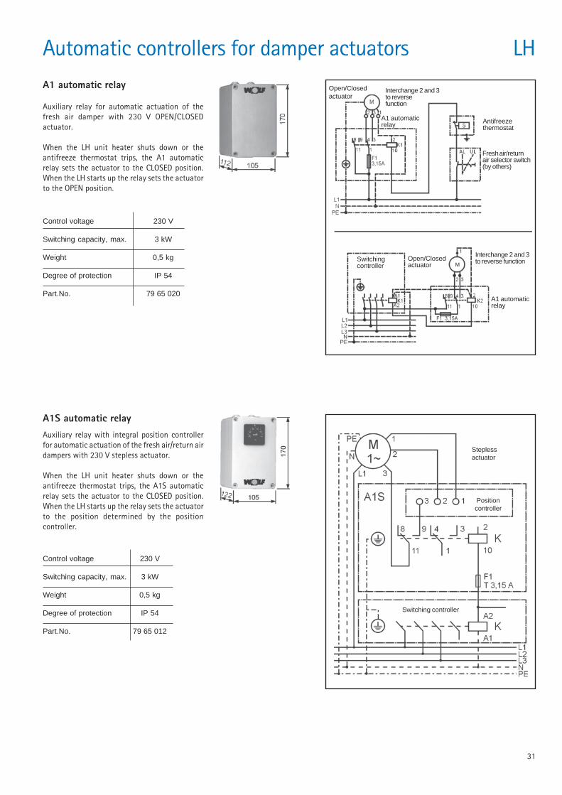
Automatic controllers for damper actuators LHA1 automatic relay
Auxiliary relay for automatic actuation of thefresh air damper with 230 V OPEN/CLOSEDactuator.
When the LH unit heater shuts down or theantifreeze thermostat trips, the A1 automaticrelay sets the actuator to the CLOSED position.When the LH starts up the relay sets the actuatorto the OPEN position.
A1S automatic relayAuxiliary relay with integral position controllerfor automatic actuation of the fresh air/return airdampers with 230 V stepless actuator.
When the LH unit heater shuts down or theantifreeze thermostat trips, the A1S automaticrelay sets the actuator to the CLOSED position.When the LH starts up the relay sets the actuatorto the position determined by the positioncontroller.
Control voltage 230 V
Switching capacity, max. 3 kW
Weight 0,5 kg
Degree of protection IP 54
Part.No. 79 65 012
Steplessactuator
Positioncontroller
Switching controller
Open/Closedactuator
Interchange 2 and 3to reversefunction
A1 automaticrelay Antifreeze
thermostat
Fresh air/returnair selector switch(by others)
Open/Closedactuator
Switchingcontroller
A1 automaticrelay
Interchange 2 and 3to reverse function
Control voltage 230 V
Switching capacity, max. 3 kW
Weight 0,5 kg
Degree of protection IP 54
Part.No. 79 65 020
32
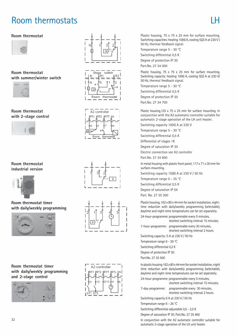
Room thermostats LHRoom thermostat Plastic housing, 75 x 75 x 25 mm for surface mounting.
Switching capacities: heating 10(4) A, cooling 5(2) A at 230 V /50 Hz, thermal feedback signal.
Temperature range 5 - 30 °C
Switching differential 0,5 K
Degree of protection IP 30
Part.No. 27 34 000
Room thermostatindustrial version
In metal housing with plastic front panel, 117 x 71 x 30 mm forsurface-mounting.
Switching capacity 15(8) A at 230 V / 50 Hz
Temperature range 0 - 35 °C
Switching differential 0,5 K
Degree of saturation IP 54
Part. No. 27 35 300
Room thermostat timerwith daily/weekly programming
Plastic housing, 162 x 80 x 44 mm for socket installation, night-time reduction with daily/weekly programming (selectable),daytime and night-time temperatures can be set separately.
24-hour-programme: programmable every 5 minutes,shortest switching interval 15 minutes.
7-hour-programme: programmable every 30 minutes,shortest switching interval 2 hours.
Switching capacity: 5 A at 230 V / 50 Hz
Temperature range 6 - 26 °C
Switching differential 0,2 K
Degree of protection IP 30
Part.No. 27 35 500
Room thermostat timerwith daily/weekly programmingand 2-stage control
Room thermostatwith 2-stage control
Plastic housing,125 x 75 x 25 mm for surface mounting. Inconjunction with the A2 automatic controller suitable forautomatic 2-stage operation of the LH unit heater.
Switching capacity 10(4) A at 230 V
Temperature range 5 - 30 °C
Switching differential 0,5 K
Differential of stages 1K
Degree of saturation IP 30
Electric connection see A2 controller
Part.No. 27 34 600
Room thermostatwith summer/winter switch
Plastic housing, 75 x 75 x 25 mm for surface mounting.Switching capacity: heating 10(4) A, cooling 5(2) A at 230 V/50 Hz, thermal feedback signal.
Temperature range 5 - 30 °C
Switching differential 0,5 K
Degree of protection IP 30
Part.No. 27 34 700
In plastic housing 162 x 80 x 44 mm for socket installation, nighttime reduction with daily/weekly programming (selectable),daytime and night-time temperatures can be set seperately.
24-hour-programme: programmable every 5 minutes,shortest switching interval 15 minutes.
7-day-programme: programmable every 30 minutes,shortest switching interval 2 hours.
Switching capacity 6 A at 230 V / 50 Hz
Temperature range 6 - 26 °C
Switching differential adjustable 0,5 - 2,5 K
Degree of saturation IP 30. Part.No. 27 35 400
In conjunction with the A2 automatic controller suitable forautomatic 2-stage operation of the LH unit heater.
33
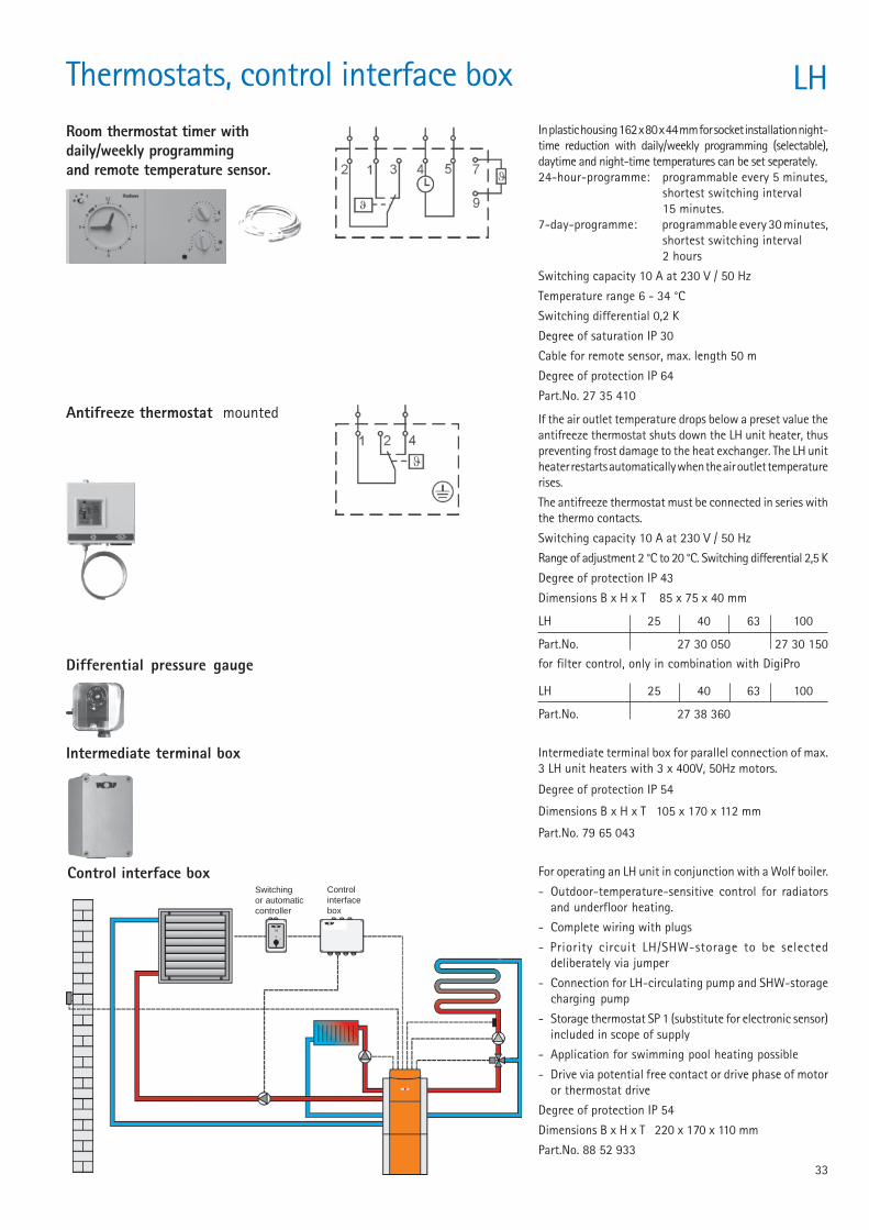
If the air outlet temperature drops below a preset value theantifreeze thermostat shuts down the LH unit heater, thuspreventing frost damage to the heat exchanger. The LH unitheater restarts automatically when the air outlet temperaturerises.
The antifreeze thermostat must be connected in series withthe thermo contacts.
Switching capacity 10 A at 230 V / 50 Hz
Range of adjustment 2 °C to 20 °C. Switching differential 2,5 K
Degree of protection IP 43
Dimensions B x H x T 85 x 75 x 40 mm
LH 25 40 63 100
Part.No. 27 30 050 27 30 150
Antifreeze thermostat mounted
Intermediate terminal box
Control interface box
Intermediate terminal box for parallel connection of max.3 LH unit heaters with 3 x 400V, 50Hz motors.
Degree of protection IP 54
Dimensions B x H x T 105 x 170 x 112 mm
Part.No. 79 65 043
For operating an LH unit in conjunction with a Wolf boiler.
- Outdoor-temperature-sensitive control for radiatorsand underfloor heating.
- Complete wiring with plugs
- Priority circuit LH/SHW-storage to be selecteddeliberately via jumper
- Connection for LH-circulating pump and SHW-storagecharging pump
- Storage thermostat SP 1 (substitute for electronic sensor)included in scope of supply
- Application for swimming pool heating possible
- Drive via potential free contact or drive phase of motoror thermostat drive
Degree of protection IP 54
Dimensions B x H x T 220 x 170 x 110 mm
Part.No. 88 52 933
Thermostats, control interface box
Switchingor automaticcontroller
Controlinterfacebox
Room thermostat timer withdaily/weekly programmingand remote temperature sensor.
In plastic housing 162 x 80 x 44 mm for socket installation night-time reduction with daily/weekly programming (selectable),daytime and night-time temperatures can be set seperately.24-hour-programme: programmable every 5 minutes,
shortest switching interval15 minutes.
7-day-programme: programmable every 30 minutes,shortest switching interval2 hours
Switching capacity 10 A at 230 V / 50 Hz
Temperature range 6 - 34 °C
Switching differential 0,2 K
Degree of saturation IP 30
Cable for remote sensor, max. length 50 m
Degree of protection IP 64
Part.No. 27 35 410
LH
Differential pressure gauge for filter control, only in combination with DigiPro
LH 25 40 63 100
Part.No. 27 38 360
34
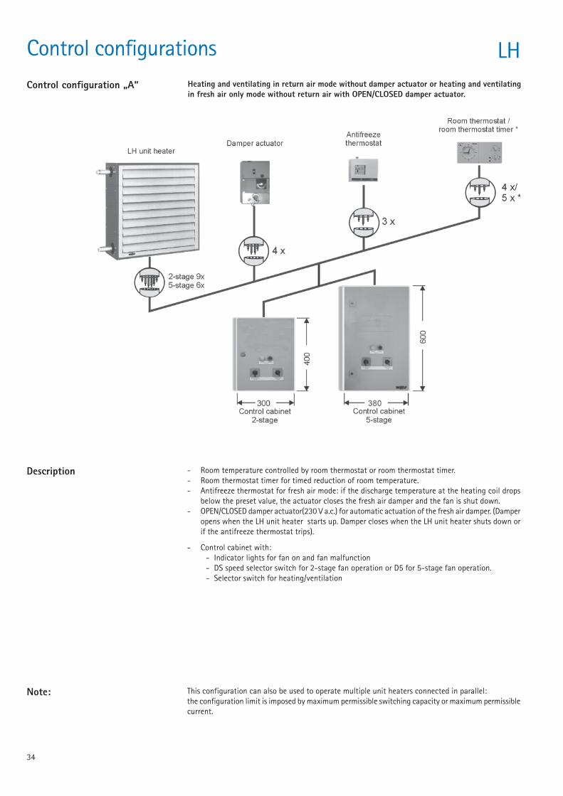
Control configurations LHControl configuration „A“ Heating and ventilating in return air mode without damper actuator or heating and ventilating
in fresh air only mode without return air with OPEN/CLOSED damper actuator.
- Room temperature controlled by room thermostat or room thermostat timer.- Room thermostat timer for timed reduction of room temperature.- Antifreeze thermostat for fresh air mode: if the discharge temperature at the heating coil drops
below the preset value, the actuator closes the fresh air damper and the fan is shut down.- OPEN/CLOSED damper actuator(230 V a.c.) for automatic actuation of the fresh air damper. (Damper
opens when the LH unit heater starts up. Damper closes when the LH unit heater shuts down orif the antifreeze thermostat trips).
- Control cabinet with:- Indicator lights for fan on and fan malfunction- DS speed selector switch for 2-stage fan operation or D5 for 5-stage fan operation.- Selector switch for heating/ventilation
This configuration can also be used to operate multiple unit heaters connected in parallel:the configuration limit is imposed by maximum permissible switching capacity or maximum permissiblecurrent.
Note:
Description
35
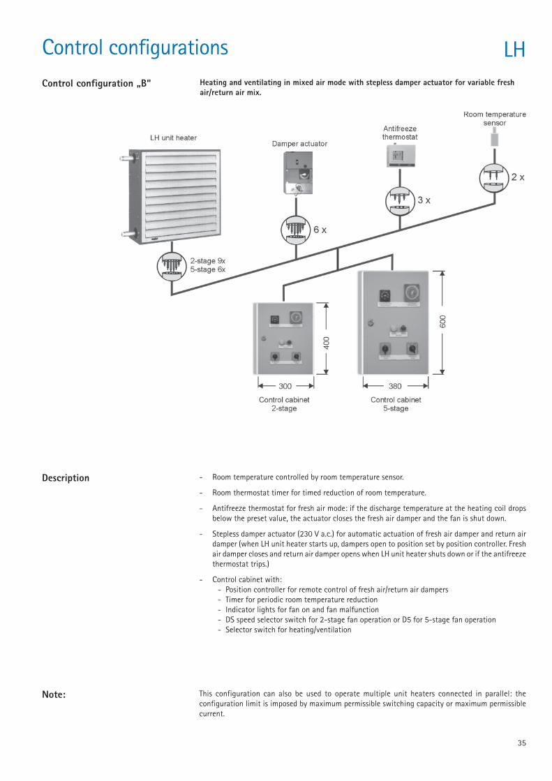
Control configurations LHControl configuration „B“ Heating and ventilating in mixed air mode with stepless damper actuator for variable fresh
air/return air mix.
- Room temperature controlled by room temperature sensor.
- Room thermostat timer for timed reduction of room temperature.
- Antifreeze thermostat for fresh air mode: if the discharge temperature at the heating coil dropsbelow the preset value, the actuator closes the fresh air damper and the fan is shut down.
- Stepless damper actuator (230 V a.c.) for automatic actuation of fresh air damper and return airdamper (when LH unit heater starts up, dampers open to position set by position controller. Freshair damper closes and return air damper opens when LH unit heater shuts down or if the antifreezethermostat trips.)
- Control cabinet with:- Position controller for remote control of fresh air/return air dampers- Timer for periodic room temperature reduction- Indicator lights for fan on and fan malfunction- DS speed selector switch for 2-stage fan operation or D5 for 5-stage fan operation- Selector switch for heating/ventilation
This configuration can also be used to operate multiple unit heaters connected in parallel: theconfiguration limit is imposed by maximum permissible switching capacity or maximum permissiblecurrent.
Note:
Description
36
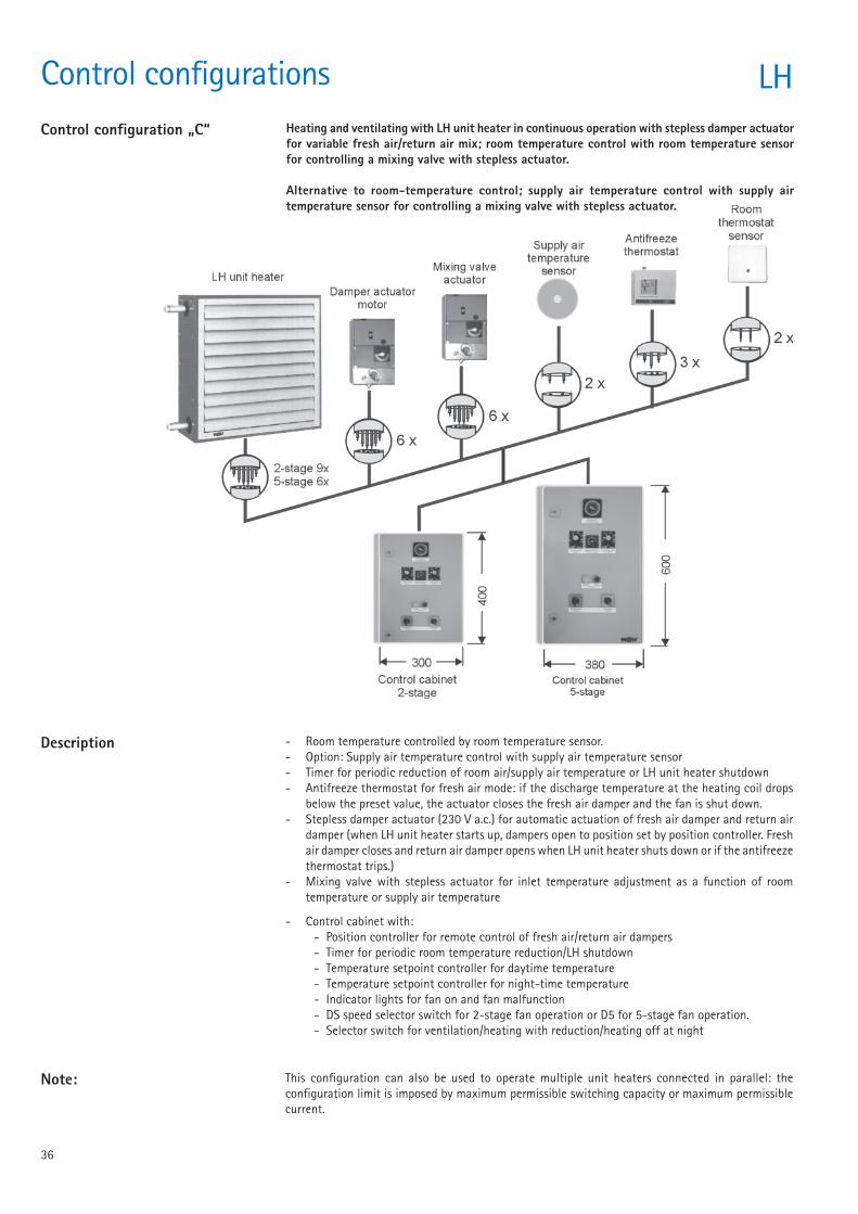
Control configurations LHControl configuration „C“ Heating and ventilating with LH unit heater in continuous operation with stepless damper actuator
for variable fresh air/return air mix; room temperature control with room temperature sensorfor controlling a mixing valve with stepless actuator.
Alternative to room-temperature control; supply air temperature control with supply airtemperature sensor for controlling a mixing valve with stepless actuator.
- Room temperature controlled by room temperature sensor.- Option: Supply air temperature control with supply air temperature sensor- Timer for periodic reduction of room air/supply air temperature or LH unit heater shutdown- Antifreeze thermostat for fresh air mode: if the discharge temperature at the heating coil drops
below the preset value, the actuator closes the fresh air damper and the fan is shut down.- Stepless damper actuator (230 V a.c.) for automatic actuation of fresh air damper and return air
damper (when LH unit heater starts up, dampers open to position set by position controller. Freshair damper closes and return air damper opens when LH unit heater shuts down or if the antifreezethermostat trips.)
- Mixing valve with stepless actuator for inlet temperature adjustment as a function of roomtemperature or supply air temperature
- Control cabinet with:- Position controller for remote control of fresh air/return air dampers- Timer for periodic room temperature reduction/LH shutdown- Temperature setpoint controller for daytime temperature- Temperature setpoint controller for night-time temperature- Indicator lights for fan on and fan malfunction- DS speed selector switch for 2-stage fan operation or D5 for 5-stage fan operation.- Selector switch for ventilation/heating with reduction/heating off at night
This configuration can also be used to operate multiple unit heaters connected in parallel: theconfiguration limit is imposed by maximum permissible switching capacity or maximum permissiblecurrent.
Note:
Description
37
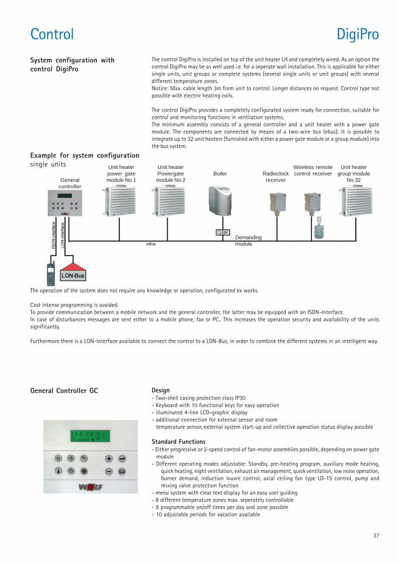
Control DigiProThe control DigiPro is installed on top of the unit heater LH and completely wired. As an option thecontrol DigiPro may be as well used i.e. for a seperate wall installation. This is applicable for eithersingle units, unit groups or complete systems (several single units or unit groups) with severaldifferent temperature zones.Notice: Max. cable length 3m from unit to control. Longer distances on request. Control type notpossible with electric heating coils.
The control DigiPro provides a completely configurated system ready for connection, suitable forcontrol and monitoring functions in ventilation systems.The minimum assembly consists of a general controller and a unit heater with a power gatemodule. The components are connected by means of a two-wire bus (ebus). It is possible tointegrate up to 32 unit heaters (furnished with either a power gate module or a group module) intothe bus system.
System configuration withcontrol DigiPro
Example for system configurationsingle units
The operation of the system does not require any knowledge or operation, configurated ex works.
Cost intense programming is avoided.To provide communication between a mobile network and the general controller, the latter may be equipped with an ISDN-Interface.In case of disturbances messages are sent either to a mobile phone, fax or PC.. This increases the operation security and availability of the unitssignificantly.
Furthermore there is a LON-Interface available to connect the control to a LON-Bus, in order to combine the different systems in an intelligent way.
General Controller GC Design- Two-shell casing protection class IP30- Keyboard with 10 functional keys for easy operation- illuminated 4-line LCD-graphic display- additional connection for external sensor and room temperature sensor, external system start-up and collective operation status display possible
Standard Functions- Either progressive or 2-speed control of fan-motor assemblies possible, depending on power gate module- Different operating modes adjustable: Standby, pre-heating program, auxiliary mode heating,
quick heating, night ventilation, exhaust air management, quick ventilation, low noise operation,burner demand, induction louvre control, axial ceiling fan type LD-15 control, pump andmixing valve protection function
- menu system with clear text display for an easy user guiding- 8 different temperature zones max. seperately controllable- 8 programmable on/off times per day and zone possible- 10 adjustable periods for vacation available
Generalcontroller
Unit heaterpower gatemodule No.1
Unit heaterPowergatemodule No.2
Boiler Radioclockreceiver
Wireless remotecontrol receiver
Unit heatergroup module
No.32
Demandingmodule
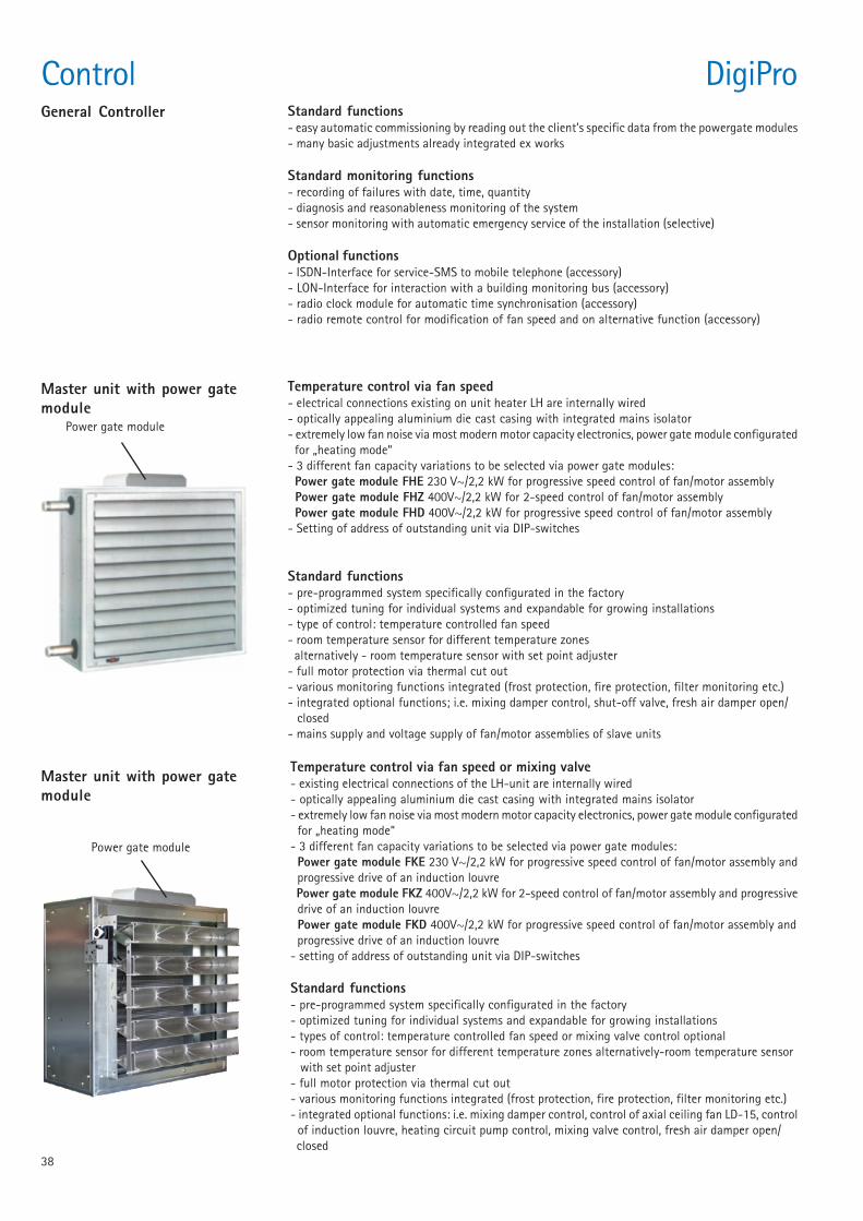
38
Temperature control via fan speed or mixing valve- existing electrical connections of the LH-unit are internally wired- optically appealing aluminium die cast casing with integrated mains isolator- extremely low fan noise via most modern motor capacity electronics, power gate module configurated for „heating mode“- 3 different fan capacity variations to be selected via power gate modules: Power gate module FKE 230 V~/2,2 kW for progressive speed control of fan/motor assembly and progressive drive of an induction louvre Power gate module FKZ 400V~/2,2 kW for 2-speed control of fan/motor assembly and progressive drive of an induction louvre Power gate module FKD 400V~/2,2 kW for progressive speed control of fan/motor assembly and progressive drive of an induction louvre- setting of address of outstanding unit via DIP-switches
Standard functions- pre-programmed system specifically configurated in the factory- optimized tuning for individual systems and expandable for growing installations- types of control: temperature controlled fan speed or mixing valve control optional- room temperature sensor for different temperature zones alternatively-room temperature sensor with set point adjuster- full motor protection via thermal cut out- various monitoring functions integrated (frost protection, fire protection, filter monitoring etc.)- integrated optional functions: i.e. mixing damper control, control of axial ceiling fan LD-15, control of induction louvre, heating circuit pump control, mixing valve control, fresh air damper open/ closed
Master unit with power gatemodule
Power gate module
Temperature control via fan speed- electrical connections existing on unit heater LH are internally wired- optically appealing aluminium die cast casing with integrated mains isolator- extremely low fan noise via most modern motor capacity electronics, power gate module configurated for „heating mode“- 3 different fan capacity variations to be selected via power gate modules: Power gate module FHE 230 V~/2,2 kW for progressive speed control of fan/motor assembly Power gate module FHZ 400V~/2,2 kW for 2-speed control of fan/motor assembly Power gate module FHD 400V~/2,2 kW for progressive speed control of fan/motor assembly- Setting of address of outstanding unit via DIP-switches
Standard functions- pre-programmed system specifically configurated in the factory- optimized tuning for individual systems and expandable for growing installations- type of control: temperature controlled fan speed- room temperature sensor for different temperature zones alternatively - room temperature sensor with set point adjuster- full motor protection via thermal cut out- various monitoring functions integrated (frost protection, fire protection, filter monitoring etc.)- integrated optional functions; i.e. mixing damper control, shut-off valve, fresh air damper open/ closed- mains supply and voltage supply of fan/motor assemblies of slave units
Master unit with power gatemodule
Power gate module
Control DigiProGeneral Controller Standard functions
- easy automatic commissioning by reading out the client’s specific data from the powergate modules- many basic adjustments already integrated ex works
Standard monitoring functions- recording of failures with date, time, quantity- diagnosis and reasonableness monitoring of the system- sensor monitoring with automatic emergency service of the installation (selective)
Optional functions- ISDN-Interface for service-SMS to mobile telephone (accessory)- LON-Interface for interaction with a building monitoring bus (accessory)- radio clock module for automatic time synchronisation (accessory)- radio remote control for modification of fan speed and on alternative function (accessory)
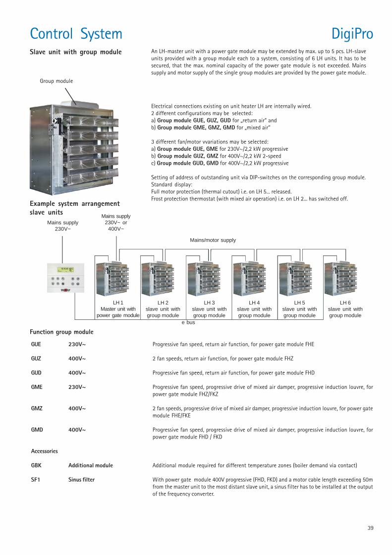
39
An LH-master unit with a power gate module may be extended by max. up to 5 pcs. LH-slaveunits provided with a group module each to a system, consisting of 6 LH units. It has to besecured, that the max. nominal capacity of the power gate module is not exceeded. Mainssupply and motor supply of the single group modules are provided by the power gate module.
Slave unit with group module
Electrical connections existing on unit heater LH are internally wired.2 different configurations may be selected:a) Group module GUE, GUZ, GUD for „return air“ andb) Group module GME, GMZ, GMD for „mixed air“
3 different fan/motor vvariations may be selected:a) Group module GUE, GME for 230V~/2,2 kW progressiveb) Group module GUZ, GMZ for 400V~/2,2 kW 2-speedc) Group module GUD, GMD for 400V~/2,2 kW progressive
Setting of address of outstanding unit via DIP-switches on the corresponding group module.Standard display:Full motor protection (thermal cutout) i.e. on LH 5... released.Frost protection thermostat (with mixed air operation) i.e. on LH 2... has switched off.
GUE 230V~ Progressive fan speed, return air function, for power gate module FHE
GUZ 400V~ 2 fan speeds, return air function, for power gate module FHZ
GUD 400V~ Progressive fan speed, return air function, for power gate module FHD
GME 230V~ Progressive fan speed, progressive drive of mixed air damper, progressive induction louvre, forpower gate module FHZ/FKZ
GMZ 400V~ 2 fan speeds, progressive drive of mixed air damper, progressive induction louvre, for power gatemodule FHE/FKE
GMD 400V~ Progressive fan speed, progressive drive of mixed air damper, progressive induction louvre, forpower gate module FHD / FKD
Accessories
GBK Additional module Additional module required for different temperature zones (boiler demand via contact)
SF1 Sinus filter With power gate module 400V progressive (FHD, FKD) and a motor cable length exceeding 50mfrom the master unit to the most distant slave unit, a sinus filter has to be installed at the outputof the frequency converter.
Function group module
Mains supply230V~
Mains supply230V~ or
400V~
Mains/motor supply
LH 1Master unit with
power gate module
LH 2slave unit withgroup module
LH 3slave unit withgroup module
LH 4slave unit withgroup module
LH 5slave unit withgroup module
LH 6slave unit withgroup module
Group module
Example system arrangementslave units
e bus
Control System DigiPro
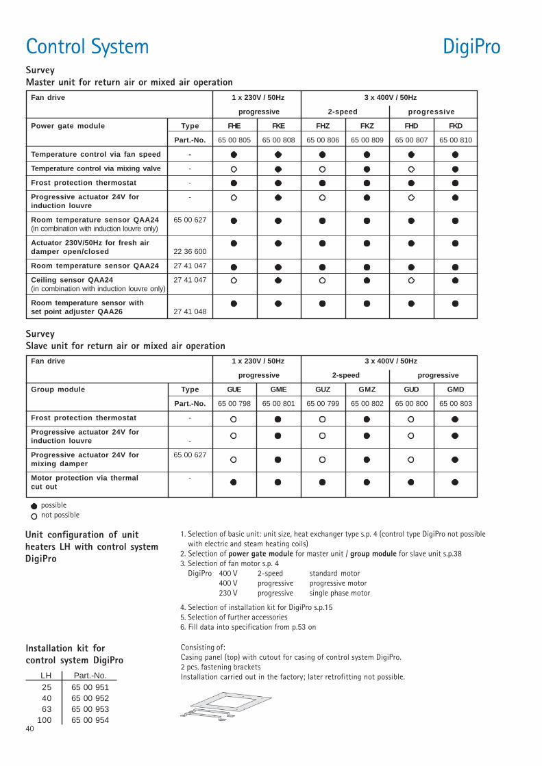
40
Control System DigiPro
Unit configuration of unitheaters LH with control systemDigiPro
1. Selection of basic unit: unit size, heat exchanger type s.p. 4 (control type DigiPro not possiblewith electric and steam heating coils)
2. Selection of power gate module for master unit / group module for slave unit s.p.383. Selection of fan motor s.p. 4
DigiPro 400 V 2-speed standard motor400 V progressive progressive motor230 V progressive single phase motor
4. Selection of installation kit for DigiPro s.p.155. Selection of further accessories6. Fill data into specification from p.53 on
SurveyMaster unit for return air or mixed air operation
SurveySlave unit for return air or mixed air operation
Fan drive 1 x 230V / 50Hz 3 x 400V / 50Hz
progressive 2-speed progressive
Group module Type GUE GME GUZ GMZ GUD GMD
Part.-No. 65 00 798 65 00 801 65 00 799 65 00 802 65 00 800 65 00 803
Frost protection thermostat -
Progressive actuator 24V forinduction louvre -
Progressive actuator 24V for 65 00 627mixing damper
Motor protection via thermal -cut out
possible not possible
Fan drive 1 x 230V / 50Hz 3 x 400V / 50Hz
progressive 2-speed progressive
Power gate module Type FHE FKE FHZ FKZ FHD FKD
Part.-No. 65 00 805 65 00 808 65 00 806 65 00 809 65 00 807 65 00 810
Temperature control via fan speed -
Temperature control via mixing valve -
Frost protection thermostat -
Progressive actuator 24V for -induction louvre
Room temperature sensor QAA24 65 00 627(in combination with induction louvre only)
Actuator 230V/50Hz for fresh airdamper open/closed 22 36 600
Room temperature sensor QAA24 27 41 047
Ceiling sensor QAA24 27 41 047(in combination with induction louvre only)
Room temperature sensor withset point adjuster QAA26 27 41 048
Installation kit forcontrol system DigiPro
Consisting of:Casing panel (top) with cutout for casing of control system DigiPro.2 pcs. fastening bracketsInstallation carried out in the factory; later retrofitting not possible.LH Part.-No.
25 65 00 95140 65 00 95263 65 00 953
100 65 00 954
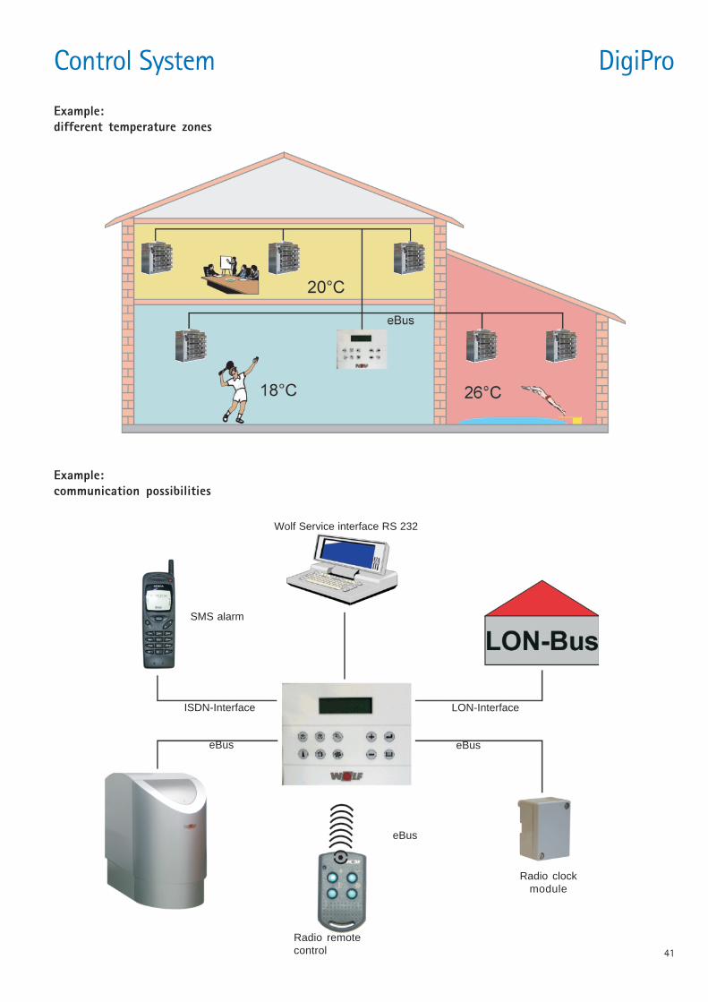
41
Example:different temperature zones
Example:communication possibilities
SMS alarm
ISDN-Interface
Wolf Service interface RS 232
LON-Interface
eBuseBus
eBus
Radio remotecontrol
Radio clockmodule
Control System DigiPro
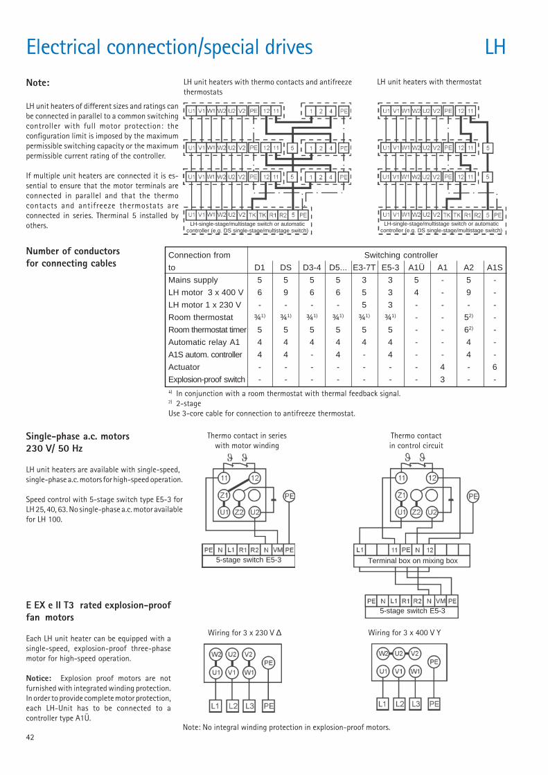
42
LH-single-stage/multistage switch or automaticcontroller (e.g. DS single-stage/multistage switch)
Connection from Switching controller
to D1 DS D3-4 D5... E3-7T E5-3 A1Ü A1 A2 A1S
Mains supply 5 5 5 5 3 3 5 - 5 -
LH motor 3 x 400 V 6 9 6 6 5 3 4 - 9 -
LH motor 1 x 230 V - - - - 5 3 - - - -
Room thermostat ¾1) ¾1) ¾1) ¾1) ¾1) ¾1) - - 52) -
Room thermostat timer 5 5 5 5 5 5 - - 62) -
Automatic relay A1 4 4 4 4 4 4 - - 4 -
A1S autom. controller 4 4 - 4 - 4 - - 4 -
Actuator - - - - - - - 4 - 6
Explosion-proof switch - - - - - - - 3 - -
-
Electrical connection/special drives LHNote:
LH unit heaters of different sizes and ratings canbe connected in parallel to a common switchingcontroller with full motor protection: theconfiguration limit is imposed by the maximumpermissible switching capacity or the maximumpermissible current rating of the controller.
If multiple unit heaters are connected it is es-sential to ensure that the motor terminals areconnected in parallel and that the thermocontacts and antifreeze thermostats areconnected in series. Therminal 5 installed byothers.
LH unit heaters with thermo contacts and antifreezethermostats
LH unit heaters with thermostat
Number of conductorsfor connecting cables
5-stage switch E5-3
Single-phase a.c. motors230 V/ 50 Hz
LH unit heaters are available with single-speed,single-phase a.c. motors for high-speed operation.
Speed control with 5-stage switch type E5-3 forLH 25, 40, 63. No single-phase a.c. motor availablefor LH 100.
E EX e II T3 rated explosion-prooffan motors
Each LH unit heater can be equipped with asingle-speed, explosion-proof three-phasemotor for high-speed operation.
Notice: Explosion proof motors are notfurnished with integrated winding protection.In order to provide complete motor protection,each LH-Unit has to be connected to acontroller type A1Ü.
Wiring for 3 x 230 V ∆
5-stage switch E5-3
Terminal box on mixing box
Wiring for 3 x 400 V Y
Thermo contact in serieswith motor winding
Thermo contactin control circuit
Note: No integral winding protection in explosion-proof motors.
1) In conjunction with a room thermostat with thermal feedback signal.2) 2-stageUse 3-core cable for connection to antifreeze thermostat.
LH-single-stage/multistage switch or automaticcontroller (e.g. DS single-stage/multistage switch)
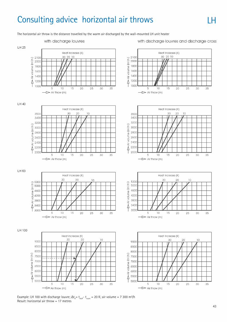
43
Consulting advice horizontal air throws LHThe horizontal air throw is the distance travelled by the warm air discharged by the wall-mounted LH unit heater
Example: LH 100 with discharge louvre; ∆tA= tAoff- troom = 20 K; air volume = 7 300 m³/hResult: horizontal air throw = 17 metres
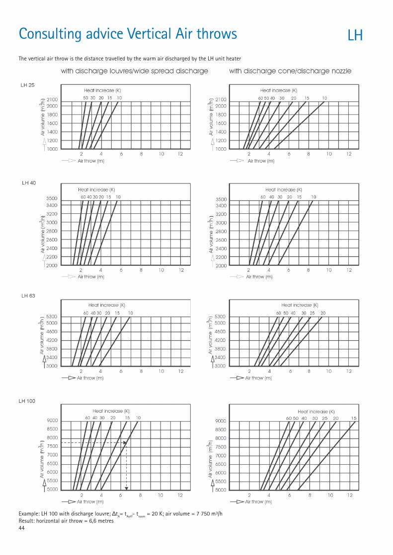
44
Consulting advice Vertical Air throws LHThe vertical air throw is the distance travelled by the warm air discharged by the LH unit heater
Example: LH 100 with discharge louvre; ∆tA= tAoff- troom = 20 K; air volume = 7 750 m³/hResult: horizontal air throw = 6,6 metres
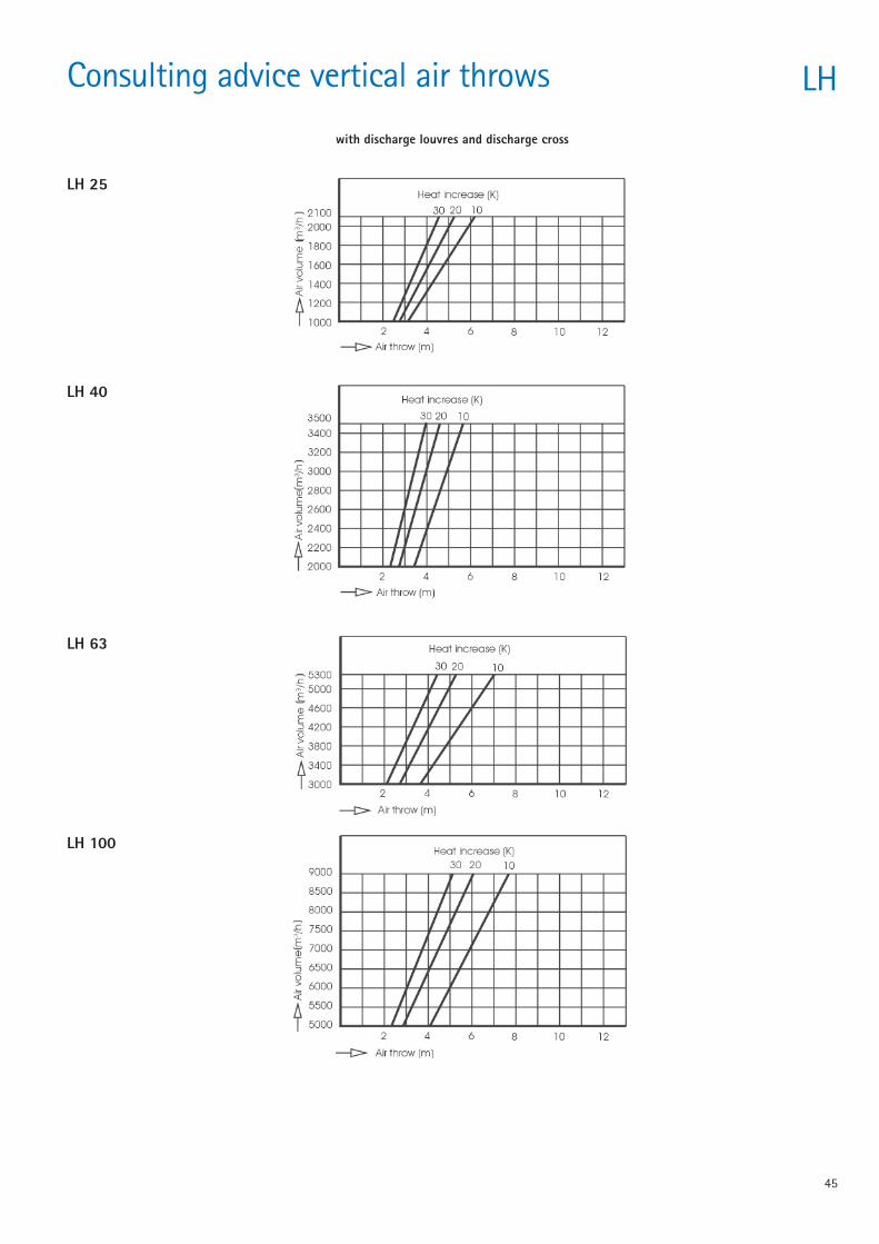
45
Consulting advice vertical air throws LH
with discharge louvres and discharge cross
LH 25
LH 40
LH 63
LH 100
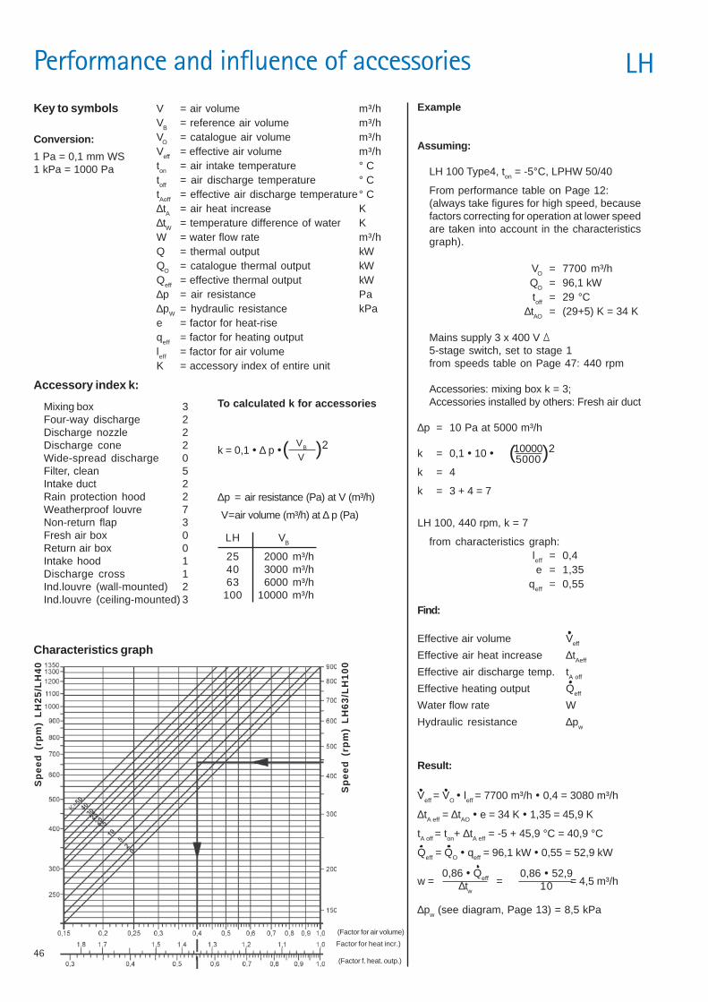
46
k = 0,1 ! ∆ p !
Example
Assuming:
LH 100 Type4, ton = -5°C, LPHW 50/40
From performance table on Page 12:(always take figures for high speed, becausefactors correcting for operation at lower speedare taken into account in the characteristicsgraph).
VO = 7700 m³/hQO = 96,1 kWtoff = 29 °C
∆tAO = (29+5) K = 34 K
Mains supply 3 x 400 V5-stage switch, set to stage 1from speeds table on Page 47: 440 rpm
Accessories: mixing box k = 3;Accessories installed by others: Fresh air duct
∆p = 10 Pa at 5000 m³/h
k = 0,1 ! 10 !
k = 4
k = 3 + 4 = 7
LH 100, 440 rpm, k = 7
from characteristics graph:leff = 0,4e = 1,35
qeff = 0,55
Find:
Effective air volume Veff
Effective air heat increase ∆tAeff
Effective air discharge temp. tA off
Effective heating output Qeff
Water flow rate W
Hydraulic resistance ∆pw
Result:
Veff = VO ! leff = 7700 m³/h ! 0,4 = 3080 m³/h
∆tA eff = ∆tAO ! e = 34 K ! 1,35 = 45,9 K
tA off = ton+ ∆tA eff = -5 + 45,9 °C = 40,9 °C
Qeff = QO ! qeff = 96,1 kW ! 0,55 = 52,9 kW
w = = = 4,5 m³/h
∆pw (see diagram, Page 13) = 8,5 kPa
0,86 ! Qeff
∆tw
Key to symbols
Conversion:
V = air volume m³/hVB = reference air volume m³/hVO = catalogue air volume m³/hVeff = effective air volume m³/hton = air intake temperature ° Ctoff = air discharge temperature ° CtAoff = effective air discharge temperature° C∆tA = air heat increase K∆tW = temperature difference of water KW = water flow rate m³/hQ = thermal output kWQO = catalogue thermal output kWQeff = effective thermal output kW∆p = air resistance Pa∆pW = hydraulic resistance kPae = factor for heat-riseqeff = factor for heating outputleff = factor for air volumeK = accessory index of entire unit
Accessory index k:
Mixing box 3Four-way discharge 2Discharge nozzle 2Discharge cone 2Wide-spread discharge 0Filter, clean 5Intake duct 2Rain protection hood 2Weatherproof louvre 7Non-return flap 3Fresh air box 0Return air box 0Intake hood 1Discharge cross 1Ind.louvre (wall-mounted) 2Ind.louvre (ceiling-mounted) 3
To calculated k for accessories
Characteristics graph
leff (Factor for air volume)
e (Factor for heat incr.)
qeff (Factor f. heat. outp.)
Sp
ee
d (
rpm
) L
H6
3/L
H1
00
1 Pa = 0,1 mm WS1 kPa = 1000 Pa
Sp
ee
d (
rpm
) L
H2
5/L
H4
0
( )2100005000
0,86 ! 52,910
LH VB
25 2000 m³/h40 3000 m³/h63 6000 m³/h
100 10000 m³/h
∆p = air resistance (Pa) at V (m³/h)
V=air volume (m³/h) at ∆ p (Pa)
VB
V( )2
Performance and influence of accessories LH
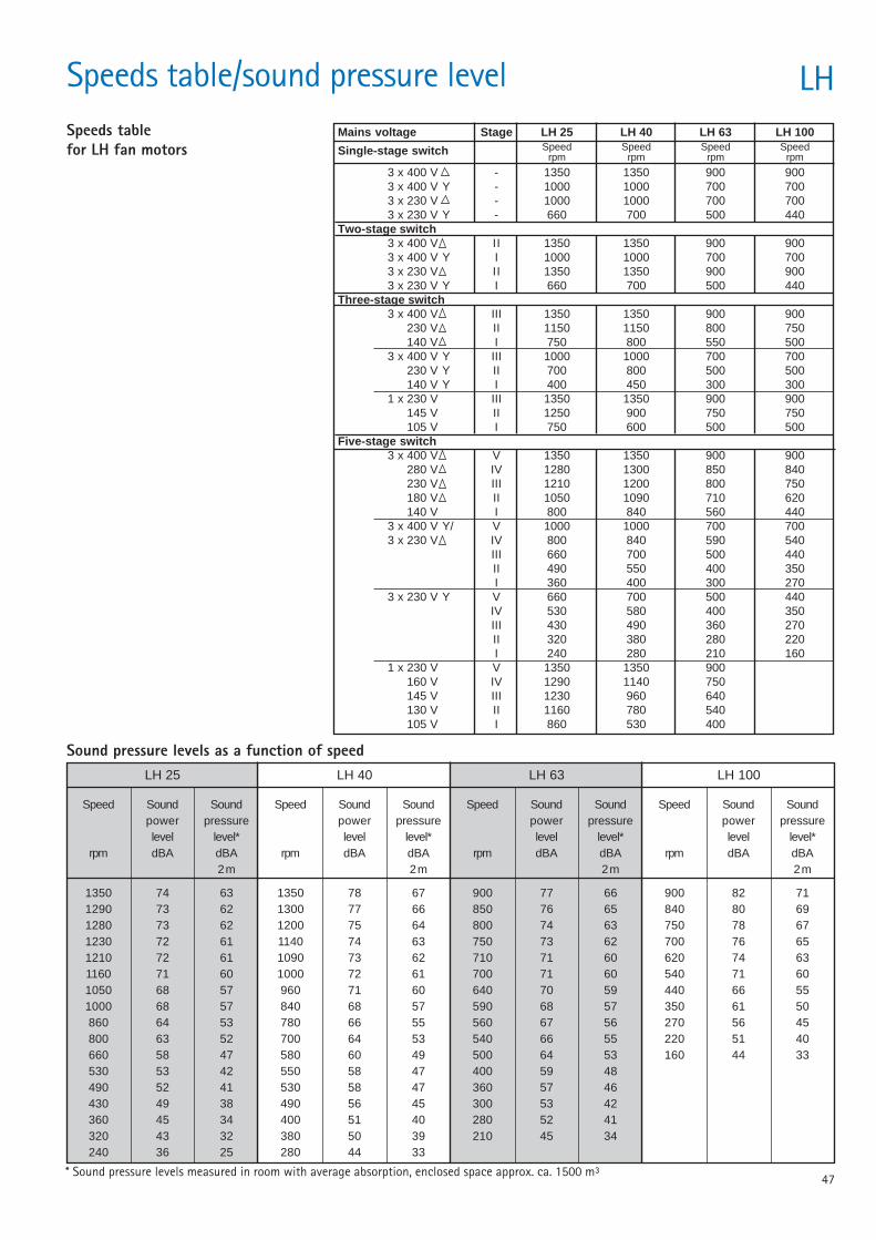
47
Speeds table/sound pressure level LHSpeeds tablefor LH fan motors
Sound pressure levels as a function of speed
Speed Sound Sound Speed Sound Sound Speed Sound Sound Speed Sound Soundpower pressure power pressure power pressure power pressurelevel level* level level* level level* level level*
rpm dBA dBA rpm dBA dBA rpm dBA dBA rpm dBA dBA2 m 2 m 2 m 2 m
1350 74 63 1350 78 67 900 77 66 900 82 711290 73 62 1300 77 66 850 76 65 840 80 691280 73 62 1200 75 64 800 74 63 750 78 671230 72 61 1140 74 63 750 73 62 700 76 651210 72 61 1090 73 62 710 71 60 620 74 631160 71 60 1000 72 61 700 71 60 540 71 601050 68 57 960 71 60 640 70 59 440 66 551000 68 57 840 68 57 590 68 57 350 61 50860 64 53 780 66 55 560 67 56 270 56 45800 63 52 700 64 53 540 66 55 220 51 40660 58 47 580 60 49 500 64 53 160 44 33530 53 42 550 58 47 400 59 48490 52 41 530 58 47 360 57 46430 49 38 490 56 45 300 53 42360 45 34 400 51 40 280 52 41320 43 32 380 50 39 210 45 34240 36 25 280 44 33
LH 25 LH 40 LH 63 LH 100
Speed Speed Speed Speedrpm rpm rpm rpm
* Sound pressure levels measured in room with average absorption, enclosed space approx. ca. 1500 m³
Mains voltage Stage LH 25 LH 40 LH 63 LH 100
Single-stage switch
3 x 400 V - 1350 1350 900 9003 x 400 V Y - 1000 1000 700 7003 x 230 V - 1000 1000 700 7003 x 230 V Y - 660 700 500 440
Two-stage switch3 x 400 V II 1350 1350 900 9003 x 400 V Y I 1000 1000 700 7003 x 230 V II 1350 1350 900 9003 x 230 V Y I 660 700 500 440
Three-stage switch3 x 400 V III 1350 1350 900 900
230 V II 1150 1150 800 750140 V I 750 800 550 500
3 x 400 V Y III 1000 1000 700 700230 V Y II 700 800 500 500140 V Y I 400 450 300 300
1 x 230 V III 1350 1350 900 900145 V II 1250 900 750 750105 V I 750 600 500 500
Five-stage switch3 x 400 V V 1350 1350 900 900
280 V IV 1280 1300 850 840230 V III 1210 1200 800 750180 V II 1050 1090 710 620140 V I 800 840 560 440
3 x 400 V Y/ V 1000 1000 700 7003 x 230 V IV 800 840 590 540
III 660 700 500 440II 490 550 400 350I 360 400 300 270
3 x 230 V Y V 660 700 500 440IV 530 580 400 350III 430 490 360 270II 320 380 280 220I 240 280 210 160
1 x 230 V V 1350 1350 900160 V IV 1290 1140 750145 V III 1230 960 640130 V II 1160 780 540105 V I 860 530 400
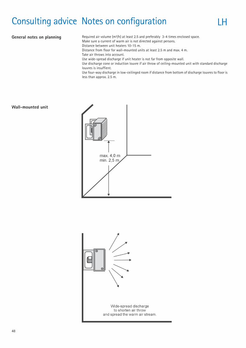
48
Consulting advice Notes on configuration LHGeneral notes on planning Required air volume (m³/h) at least 2.5 and preferably 3-4 times enclosed space.
Make sure a current of warm air is not directed against persons.Distance between unit heaters 10-15 m.Distance from floor for wall-mounted units at least 2.5 m and max. 4 m.Take air throws into account.Use wide-spread discharge if unit heater is not far from opposite wall.Use discharge cone or induction louvre if air throw of ceiling-mounted unit with standard dischargelouvres is insuffient.Use four-way discharge in low-ceilinged room if distance from bottom of discharge louvres to floor isless than approx. 2.5 m.
Wall-mounted unit
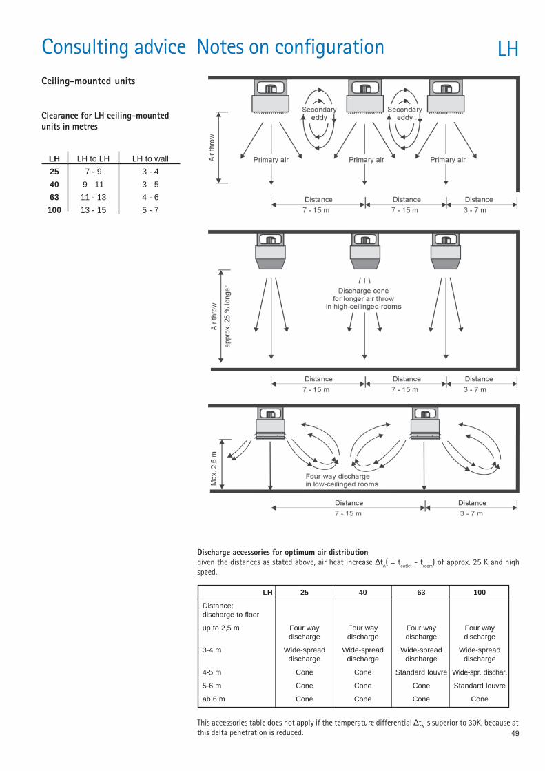
49
LH 25 40 63 100
Distance:discharge to floor
up to 2,5 m Four way Four way Four way Four waydischarge discharge discharge discharge
3-4 m Wide-spread Wide-spread Wide-spread Wide-spreaddischarge discharge discharge discharge
4-5 m Cone Cone Standard louvre Wide-spr. dischar.
5-6 m Cone Cone Cone Standard louvre
ab 6 m Cone Cone Cone Cone
Consulting advice Notes on configuration LHCeiling-mounted units
Clearance for LH ceiling-mountedunits in metres
LH LH to LH LH to wall
25 7 - 9 3 - 4
40 9 - 11 3 - 5
63 11 - 13 4 - 6
100 13 - 15 5 - 7
Discharge accessories for optimum air distributiongiven the distances as stated above, air heat increase ∆tA( = toutlet - troom) of approx. 25 K and highspeed.
This accessories table does not apply if the temperature differential ∆tA is superior to 30K, because atthis delta penetration is reduced.
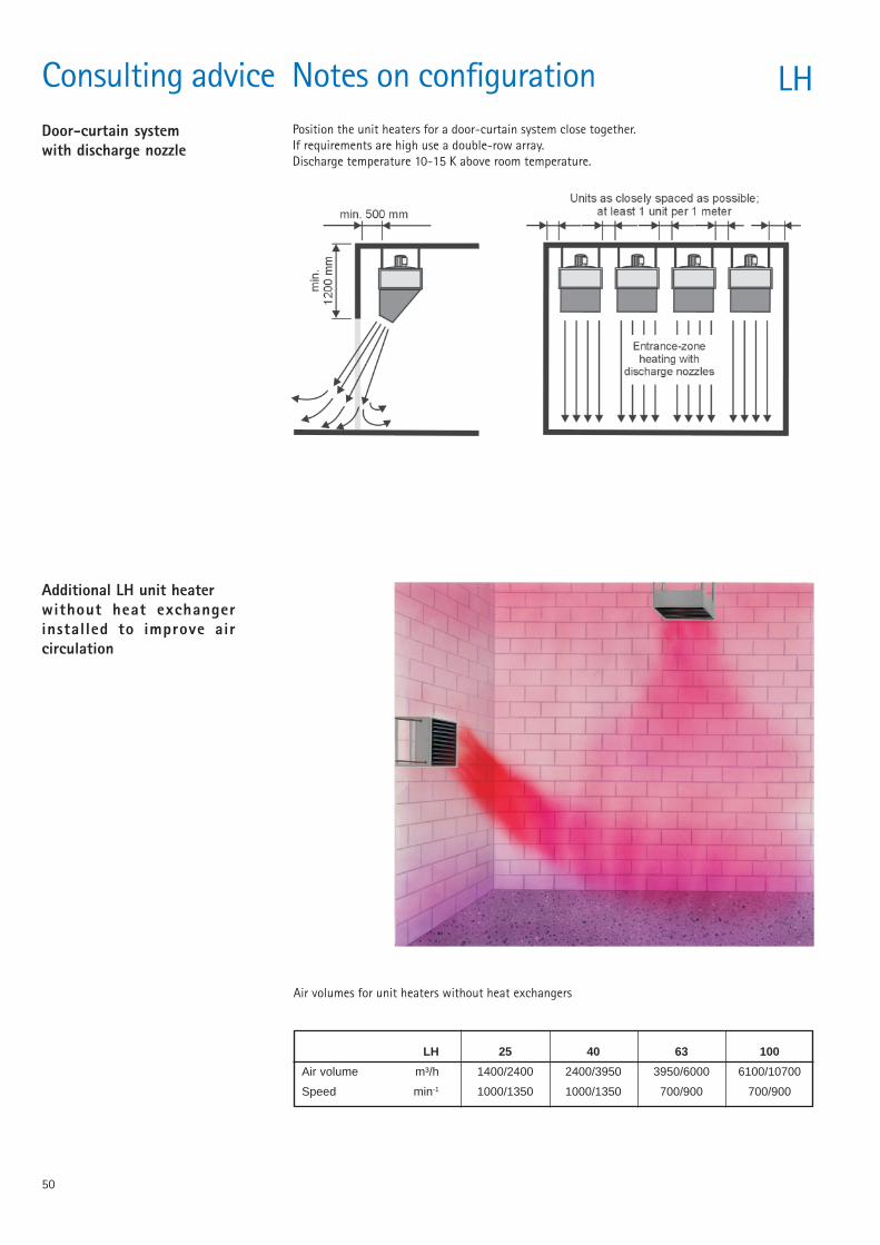
50
Consulting advice Notes on configuration LHDoor-curtain systemwith discharge nozzle
Position the unit heaters for a door-curtain system close together.If requirements are high use a double-row array.Discharge temperature 10-15 K above room temperature.
Additional LH unit heaterwithout heat exchangerinstalled to improve aircirculation
Air volumes for unit heaters without heat exchangers
LH 25 40 63 100
Air volume m³/h 1400/2400 2400/3950 3950/6000 6100/10700
Speed min-1 1000/1350 1000/1350 700/900 700/900
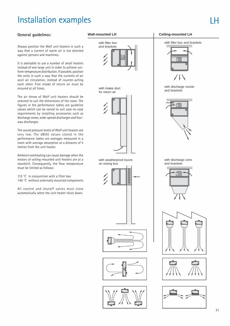
51
Installation examples LH
Always position the Wolf unit heaters in such away that a current of warm air is not directedagainst persons and machines.
It is advisable to use a number of small heatersinstead of one large unit in order to achieve uni-form temperature distribution. If possible, positionthe units in such a way that the currents of airassit air circulation, instead of counter-actingeach other. Free intake of return air must beensured at all times.
The air throw of Wolf unit heaters should beselected to suit the dimensions of the room. Thefigures in the performance tables are guidelinevalues which can be varied to suit case-to-caserequirements by installing accessories such asdischarge cones, wide-spread discharges and four-way discharges.
The sound pressure levels of Wolf unit heaters arevery low. The dB(A) values stated in theperformance tables are averages measured in aroom with average absorption at a distance of 5metres from the unit heater.
Ambient overheating can cause damage when themotors of ceiling-mounted unit heaters are at astandstill. Consequently, the flow temperaturemust be limited as follows:
115 °C in conjunction with a filter box140 °C without externally mounted components
All control and shutoff valves must closeautomatically when the unit heater shuts down.
General guidelines: Wall-mounted LH Ceiling-mounted LH
with filter boxand brackets
with filter box and brackets
with discharge nozzleand brackets
with discharge coneand brackets
with intake ductfor return air
with weatherproof louvreon mixing box
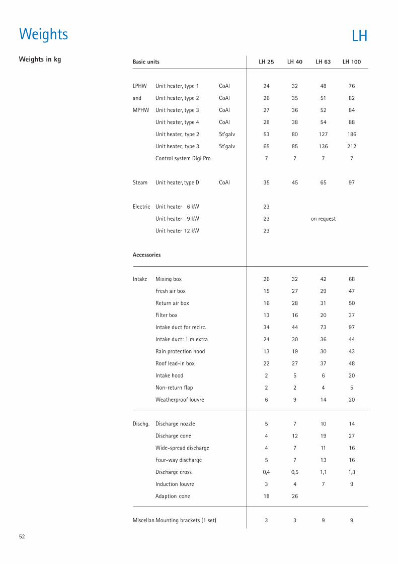
52
Weights LHWeights in kg Basic units LH 25 LH 40 LH 63 LH 100
LPHW Unit heater, type 1 CoAl 24 32 48 76
and Unit heater, type 2 CoAl 26 35 51 82
MPHW Unit heater, type 3 CoAl 27 36 52 84
Unit heater, type 4 CoAl 28 38 54 88
Unit heater, type 2 St’galv 53 80 127 186
Unit heater, type 3 St’galv 65 85 136 212
Control system Digi Pro 7 7 7 7
Steam Unit heater, type D CoAl 35 45 65 97
Electric Unit heater 6 kW 23
Unit heater 9 kW 23 on request
Unit heater 12 kW 23
Accessories
Intake Mixing box 26 32 42 68
Fresh air box 15 27 29 47
Return air box 16 28 31 50
Filter box 13 16 20 37
Intake duct for recirc. 34 44 73 97
Intake duct: 1 m extra 24 30 36 44
Rain protection hood 13 19 30 43
Roof lead-in box 22 27 37 48
Intake hood 2 5 6 20
Non-return flap 2 2 4 5
Weatherproof louvre 6 9 14 20
Dischg. Discharge nozzle 5 7 10 14
Discharge cone 4 12 19 27
Wide-spread discharge 4 7 11 16
Four-way discharge 5 7 13 16
Discharge cross 0,4 0,5 1,1 1,3
Induction louvre 3 4 7 9
Adaption cone 18 26
Miscellan.Mounting brackets (1 set) 3 3 9 9
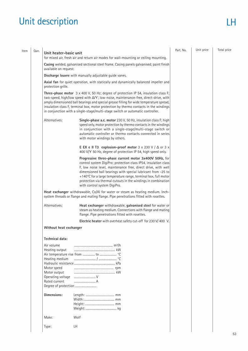
53
Part. No.
Unit description LH
Item Qan. Total priceUnit priceUnit heater-basic unitfor mixed air, fresh air and return air modes for wall-mounting or ceiling mounting.
Casing welded, galvanised sectional steel frame. Casing panels galvanised; paint finishavailable on request.
Discharge louvre with manually adjustable guide vanes.
Axial fan for quiet operation, with statically and dynamically balanced impeller andprotection grille.
Three-phase motor 3 x 400 V, 50 Hz; degree of protection IP 54, insulation class F;two-speed, high/low speed with ∆/Υ; low-noise, maintenance-free, direct-drive, withamply dimensioned ball bearings and special grease filling for wide temperature spread,insulation class F, terminal box, motor protection by thermo contacts in the windingsin conjunction with a single-stage/multi-stage switch or automatic controller.
Alternatives: Single-phase a.c. motor 230 V, 50 Hz, insulation class F; highspeed only, motor protection by thermo contacts in the windingsin conjunction with a single-stage/multi-stage switch orautomatic controller or thermo contacts connected in serieswith motor windings by others.
E EX e II T3 explosion-proof motor 3 x 230 V / ∆ or 3 x400 V/Υ 50 Hz, degree of protection IP 54, high speed only.
Progressive three-phase current motor 3x400V 50Hz, forcontrol system DigiPro; protection class IP54, insulation classF, low noise level, maintenance free, direct drive, with welldimensioned ball bearings with special lubricant from -25 to+140°C for a large temperature range, terminal box, full motorprotection via thermal cutouts in the windings in combinationwith control system DigiPro.
Heat exchanger withdrawable, Co/Al for water or steam as heating medium. Inch-system threads or flange and mating flange. Pipe penetrations fitted with rosettes.
Alternatives: Heat exchanger withdrawable, galvanised steel for water orsteam as heating medium. Connections with flange and matingflange. Pipe penetrations fitted with rosettes.
Electric heater with overheat safety cut-off for 230 V/ 400 V.
Without heat exchanger
Technical data:
Air volume .................................................. m³/hHeating output ..................................................... kWAir temperature rise from ................ to ...................... °CHeating medium ............................ / ....................... °CHydraulic resistance ..................................................... kPaMotor speed ................................................... rpmMotor output ..................................................... kWOperating voltage ............................ VRated current ............................ ADegree of protection ............................
Dimensions: Length: ..................................... mmWidth: ....................................... mmHeight: ...................................... mmWeight: ........................................ kg
Make: Wolf
Type: LH
54
Unit description LH
Item Quan. Total priceUnit priceIntake accessories
Mixing box galvanised, with two integrated dampers for fresh air at rear and returnair at side; adjustment manual or with damper actuator.
Fresh air box galvanised, with air intake at rear for connection to a wall shaft or airintake duct
Damper for fresh air, galvanized
Return air box galvanized, with two side mesh guards for air intake from side or topand bottom
Filter box galvanized, with integrated replaceable filter element, filter class G 4
Intake duct for return air length ..................... m
Rain protection hood with intake hood and bird screen, galvanized sheet steel.
Roof lead-in box, galvanized sheet steel
Covering collar for roof passage, galvanized sheet steel
Intake hood with bird screen, galvanized sheet steel
Non-return flap for rain protection hood/intake hood
Weatherproof louvre with bird screen without non-return flap, galvanized sheetsteel
Weatherproof louvre with bird screen and non-return flap, galvanized sheet steel
Flexible connection 4-hole profile, galvanized sheet steel.
Discharge accessories
Discharge nozzle for longer air throw, suitable for air curtains, galvanized sheet steel.
Discharge cone for high-ceilinged rooms, for longer air throws, galvanized sheetsteel.
Wide-spread discharge with individually adjustable vertical and horizontal air vanesfor spreading air current up to max.120° angle, galvanized sheet steel.
Four-way discharge with adjustable side vanes for low-ceilinged rooms,galvanized sheet steel.
Discharge cross for better ventilation and low air temperature close to ceiling,galvanized sheet steel.
Induction louvre for wall-mounted unit heaters with manual adjustment for optimisingair throw and temperature distribution, galvanized sheet steel.
Induction louvre for wall-mounted unit heaters with 230 V positioning motor foroptimising air throw and temperature distribution, galvanized sheet steel.
Induction louvre for ceiling-mounted unit heaters with manual adjustment foroptimising air throw and temperature distribution, galvanized sheet steel.
Induction louvre for ceiling-mounted unit heaters with 230 V positioning motor foroptimising air throw and temperature distribution, galvanized sheet steel.
Part. No.
55
Unit description LH
Item Qan. Total price Unit priceInduction louvre for wall-mounted with 24 V positioning motor
Induction louvre for ceiling-mounted with 24 V positioning motor
Options
Shut-off set for flow and return, straight way type
Shut-off set for flow and return, rectangular type
Fastening brackets for wall and ceiling installation of LH-Unit, galvanized sheetsteel.
Fastening set for the installation of an LH-Unit on a vertical concrete bar, galvanizedsheet steel.
Fastening set for the installation of an LH-Unit on a vertical steel bar, galvanizedsheet steel.
Fastening set for the installation of an LH-Unit on a horizontal or inclined steel bar,without inclination equalization, galvanized sheet steel.
Fastening set for the installation of an LH-Unit on an inclined steel bar, with inclinationequalization, galvanized sheet steel.
Angle brackets for wall or ceiling installation, of the air intake accessery, galvanizedsheet steel.
Part. No.
20 08 030
20 08 040
65 11 454
Electrical accessories
Single-stage switch D1 Full motor protection for single-speed fan operation. Maxswitching 3 kW, operating voltage 400 V, control voltage 230 V, degree of protectionIP 54; dimensions W x H x D:105 x 170 x 135 mm.
Two-stage switch DS Full motor protection for two-speed fan operation.Max. switching 4 kW, operating voltage 400 V, control voltage 230 V, degree ofprotection IP 54; dimensions W x H x D: 105 x 170 x 135 mm.
Three-stage switch E3-7T Full motor protection with reclosing lock-out for three-speed fan operation with single-phase AC-motorMax. current 7 A, operating voltage 230 V, degree of protection IP 40, dimensionsW x H x D: 150 x 200 x 150 mm.
Three-stage switch D 3-4 Full motor protection with reclosing lock-out for three-speed fan operation.Max. current 4 A, operating voltage 400 V, control voltage 230 V,degree of protection IP 20; dimensions W x H x D: 230 x 300 x 165 mm.
Five-stage switch D5-1 Full motor protection for five-speed fan operation.Max. current 1 A, operating voltage 400 V, control voltage 230 V, degree of protectionIP 40; dimensions W x H x D: 150 x 200 x 175 mm.
Five-stage switch D5-3 Full motor protection for five-speed fan operation.Max. current 2 A, operating voltage 400 V, control voltage 230 V,degree of protection IP 20; dimensions W x H x D: 230 x 310 x 185 mm.
Five-stage switch D5-7 Full motor protection for five-speed fan operation.Max. current 4 A, operating voltage 400 V, control voltage 230 V,degree of protection IP 20; dimensions W x H x D: 230 x 310 x 185 mm.
79 40 001
79 25 110
27 01 064
27 01 065
27 40 015
27 40 010
27 40 013
56
Unit description LH
Item Qan. Total priceUnit pricePart. No.
Five-stage switch D5-12 Full motor protection for five-speed fan operation.Max. current 7 A, operating voltage 400 V, control voltage 230 V,degree of protection IP 20; dimensions W x H x D: 230 x 310 x 185 mm.
Five-stage switch E5-3 Full motor protection for five-speed fan operation withsingle-phase a.c. motorMax. current 3 A, operating voltage 230 Vdegree of protection IP 40; dimensions B x H x T: 150 x 200 x 175 mm.
Five-stage switch E5-7 T Full motor protection for five speed fan operation withsingle-phase a.c. motorMax current 7 A, operating voltage 230 VDegree of protection IP 40; dimensions B x H x T: 150 x 200 x 175 mm.
A1Ü automatic controller (without explosion-proof switch) Full motor protectionfor single-speed fan operation with explosion-proof LH motors; max. switching capacity3 kW, operating voltage 3 x 400 V, control voltage 230 V, degree of protection IP 54;dimensions B x H x T: 150 x 200 x 125 mm.
Explosion-proof switch for A1Ü automatic controller.
A2 automatic controller for automatic two-speed fan operation only in conjunctionwith a 2-stage room thermostat; part No. 273 34600 or a 2-stage room thermostatpart No. 273 5400;dimensions B x H x T: 170 x 220 x 110 mm.
Control interface box for connection to Wolf boiler control system.
Intermediate terminal box for parallel operation of max. 3 LH unit heaters.
All-pole Isolator AR8, installed and fully wired.
Earthing strap for potential equalization
Antifreeze thermostat mounted on LH unit heater
Room thermostat for surface mounting, with thermal feedback signal.Switching capacity 10(4) A at 230 V, temperature range 5-30°C,degree of protection IP 30; dimensions B x H x T: 75 x 75 x 25 mm.
Room thermostat with 2-stage control for surface mounting, with thermal feedback,in conjunction with A2 automatic controller suitable for 2-stage operation of the LHfan.Switching capacity 10(4) A at 230 V, temperature range 5-30 °C, degree of protectionIP 30; dimensions B x H x T: 125 x 75 x 25 mm.Switching differential 0,5 KStufenabstand 1 K
Room thermostat with summer/winter switch for heating/ventilation; for surfacemounting, with thermal feedback signal.Switching capacity 6 (3) A at 230 V, temperature range 5-30 °C,degree of protection IP 30; dimensions B x H X T: 117 x 71 x 30 mm.
Room thermostat timer with daily/weekly programming for socket installation,daily/weekly programming (selectable), daytime and night-time temperatures can beset separately.Switching capacity 5 A at 230 V, temperature range 6-26 °C, degree of protectionIP 30; dimensions B x H X T: 162 x 80 x 44 mm.
27 40 014
27 40 006
27 40 001
79 65 030
27 39 000
79 25 130
8852 933
74 65 043
79 65 015
27 65 450
27 30 050
27 34 000
27 34 600
27 34 700
27 35 500
57
Item Quan. Total priceUnit pricePart. No.
Room thermostat timer with 2-stage control and daily/weekly programmingdaily/weekly programming (selectable), daytime and night-time temperatures can be setseparately; in conjunction with A2 automatic controller suitable for automatic 2-stage operationof the LH fan.Switching capacity 6 A at 230 V, temperature range 6-26 °C, degree of protection IP 30;dimensions B x H x T: 162 x 80 x 44 mm.
Room thermostat timer with daily/weekly programming and remote temperature sensorwith daily/weekly programming (selectable) daytime and night-time temperatures can be setseparately; temperature sensor with 2 m cable and wall mount for sensor.Switching capacity 10 A at 230 V, temperature range 6-34 °C, degree of protection IP 30;dimensions B x H x T: 162 x 80 x 44 mm.
Room thermostat, industrial versionSwitching capacity 15 (8) A at 230 V, temperature range 0-35 °C, degree of protection IP 54;dimensions B x H x T: 87 x 123 x 83 mm.
Actuator for stepless control of damper or mixing valve 230 V / 50 Hz .
Actuator for damper open/closed 230 V / 50 Hz.
Automatic relay A1 for open/closed actuator.
Automatic relay A1S with position controller for stepless actuator.
Position controller for front-panel installation in control cabinet for controlling the steplessactuator in conjunction with automatic relay A1.
Position controller for surface mounting for controlling the stepless actuator in conjunctionwith automatic relay A1.
Key button for actuator 230 V / 50 Hz for induction louvre.
Basic components of DigiPro
General controller GCsuitable for microprocessor control of unit heaters in combination with the power gate andgroup modules, provided with an easy 10 key operation; 4 line display
Power gate module FHE230V~2,2kW, for progressive control of the fan/motor assembly
Power gate module FHZ400V~2,2 kW, for 2-speed control of the fan/motor assembly
Power gate module FHD400V~/2,2 kW; for progressive control of the fan/motor assembly
Power gate module FKE230V~ / 2,2kW; for progressive control of the fan/motor assembly and progressive drive of theinduction louvre
Powergate module FKZ400V~ / 2,2kW; for 2-speed control of the fan/motor assembly and progressive drive of theinduction louvre
Leistungsteil FKD400V~ / 2,2kW; for progressive control of the fan/motor assembly and progressive drive of theinduction louvre
Group module GUE, 230V~ /return air/ progressive, for power gate module FHE
27 35 400
27 35 410
27 35 300
22 36 550
22 36 600
79 65 020
79 65 012
27 41 155
79 65 022
27 01 063
27 01 000
65 00 805
65 00 806
65 00 807
65 00 808
65 00 809
65 00 810
65 00 798
Unit description LH
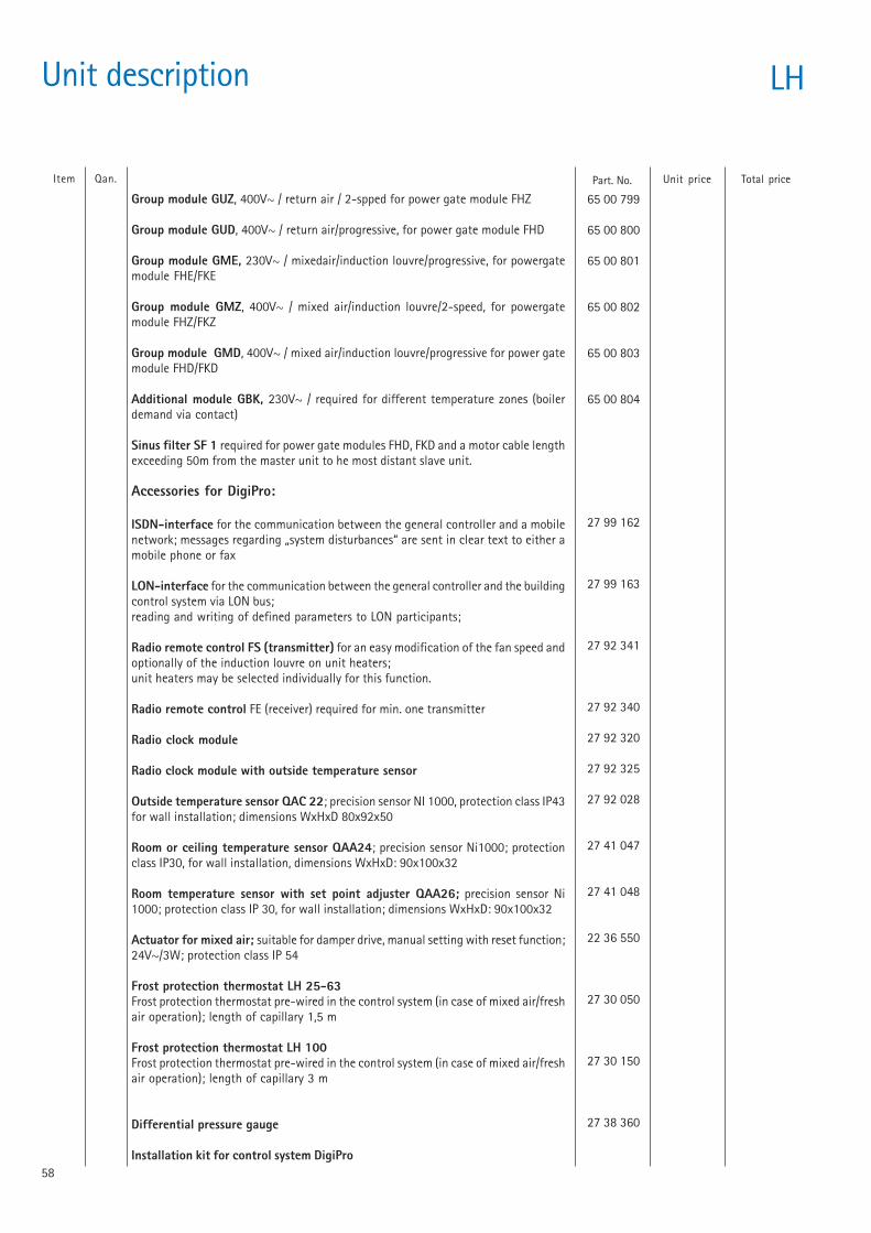
58
Unit description LH
65 00 799
65 00 800
65 00 801
65 00 802
65 00 803
65 00 804
27 99 162
27 99 163
27 92 341
27 92 340
27 92 320
27 92 325
27 92 028
27 41 047
27 41 048
22 36 550
27 30 050
27 30 150
27 38 360
Item Qan. Total priceUnit price
Group module GUZ, 400V~ / return air / 2-spped for power gate module FHZ
Group module GUD, 400V~ / return air/progressive, for power gate module FHD
Group module GME, 230V~ / mixedair/induction louvre/progressive, for powergatemodule FHE/FKE
Group module GMZ, 400V~ / mixed air/induction louvre/2-speed, for powergatemodule FHZ/FKZ
Group module GMD, 400V~ / mixed air/induction louvre/progressive for power gatemodule FHD/FKD
Additional module GBK, 230V~ / required for different temperature zones (boilerdemand via contact)
Sinus filter SF 1 required for power gate modules FHD, FKD and a motor cable lengthexceeding 50m from the master unit to he most distant slave unit.
Accessories for DigiPro:
ISDN-interface for the communication between the general controller and a mobilenetwork; messages regarding „system disturbances“ are sent in clear text to either amobile phone or fax
LON-interface for the communication between the general controller and the buildingcontrol system via LON bus;reading and writing of defined parameters to LON participants;
Radio remote control FS (transmitter) for an easy modification of the fan speed andoptionally of the induction louvre on unit heaters;unit heaters may be selected individually for this function.
Radio remote control FE (receiver) required for min. one transmitter
Radio clock module
Radio clock module with outside temperature sensor
Outside temperature sensor QAC 22; precision sensor NI 1000, protection class IP43for wall installation; dimensions WxHxD 80x92x50
Room or ceiling temperature sensor QAA24; precision sensor Ni1000; protectionclass IP30, for wall installation, dimensions WxHxD: 90x100x32
Room temperature sensor with set point adjuster QAA26; precision sensor Ni1000; protection class IP 30, for wall installation; dimensions WxHxD: 90x100x32
Actuator for mixed air; suitable for damper drive, manual setting with reset function;24V~/3W; protection class IP 54
Frost protection thermostat LH 25-63Frost protection thermostat pre-wired in the control system (in case of mixed air/freshair operation); length of capillary 1,5 m
Frost protection thermostat LH 100Frost protection thermostat pre-wired in the control system (in case of mixed air/freshair operation); length of capillary 3 m
Differential pressure gauge
Installation kit for control system DigiPro
Part. No.

59

60
Technology for life.
Wolf GmbH, Postfach 1380, D-84048 Mainburg, Telefon +49(0)8751/74-0, Telefax +49(0)8751/741600, Internet: www.wolf-heiztechnik.de
4 / 0
3 H
&N
E
Ände
rung
en v
orbe
halt
en