(universität stuttgart, ss09) topic: fault tolerant ... · universität stuttgart 1 seminar ......
TRANSCRIPT

Institut für Technische Informatik Prof. Dr. M. Radetzki - Prof. Dr. H.-J. Wunderlich
Universität Stuttgart
1
Seminar
Reliable Networks-On-Chip in the Many Core Era
(Universität Stuttgart, SS09)
Topic:
Fault Tolerant Network on chips Topologies
Presented: Tharesh Sharma Mentor : Claus Braun
Date : July 7, 2009
Institut für Technische Informatik Prof. Dr. M. Radetzki - Prof. Dr. H.-J. Wunderlich Universität Stuttgart
Institut für Technische Informatik Prof. Dr. M. Radetzki - Prof. Dr. H.-J. Wunderlich
Universität Stuttgart
2
Table of Contents
1. Introduction …………………………………………………… 1-2
2. The NoC Design Space ……………………………………… 2-9 2.1 NoC Components 2.2 NoC Topologies 2.3 NoC Switching Technique 2.4 NoC Routing 2.5 Fault 2.6 Hierarchial Partitioning Fault Tolerance NoC System 2.7 Quality-of-Service (QoS)
3. Fault Tolerant NoC Topologies………………………………9-20 3.1 Crossbar: 3.2. N-dimensional k-ary mesh: 3.3 d-dimenstional k-ary (fat trees): 3.4 Generalized de Bruijn Graph
3.4.1 NoC Design based on de Bruijn Graph 3.4.1.1 Switch structure 3.4.1.2 Topology 3.4.1.3 Routing 3.4.1.4 Reliable Switch
3.5 QRDT Structure and its Network properties 3.5.1Fault Tolerance Routing for QRDT under Single Link/Node Failure
4. Conclusion……………………………………………………….21
References …………………………………………………………..22

Institut für Technische Informatik Prof. Dr. M. Radetzki - Prof. Dr. H.-J. Wunderlich
Universität Stuttgart
3
List of Figures
Figure 1 : Regular NoC Structure Figure 2 : Packet Structure Figure 3 : Hierarchical partitioning for fault-tolerant NoC. Figure 4 : Cross Bar Topology Figure 5 : Butterfly Fat Tree Figure 6 : De Bruijn Graph (d,n) Figure 7 : NoC Switch Figure 8 : Circular FIFO for Virtual Channel Figure 9a : Tree-1 Figure 9b : Tree-2 Figure 10 : Routing Method Figure 11 : GDB(2,14) with link labels and relations Figure 12 : Parents, siblings and their relations. Figure 13 : Structure of 4-QRDT Figure 14a : Direction of 8 channels Figure 14b : Coordinates of 8 connected to (x,y) through the channels Figure 15a : Two case under single link fault Figure 15b : Two case under single node fault
Institut für Technische Informatik Prof. Dr. M. Radetzki - Prof. Dr. H.-J. Wunderlich
Universität Stuttgart
4
1. Introduction From the times of vacuum tubes (which occupied huge floor area) to present day nano-scale transistor, we have come up a long way. In particular, last two decades had seen unprecedented shrinking of the transistors. So far, this scaling down has obeyed Moore's Law. According to Moore's law, integration complexity doubles approximately every 1 to 2 years. [1] However, very soon we will see technologies posing new challenges to this primal law which has governed the dynamics of transistor scaling.
The present state-of-the-art technology is of the order of 65 nm. But, several major companies are ready with 45 nm chips. And recently INTEL announced their plan for 25 nm chips. As predicted by Steve Furber, [European Test Symposium 2006] “Within a decade we will see 100 billion transistor chips. That is the good news. The bad news is that 20 billion of those transistors will fail in manufacture and a further 10 billion will fail in the first year of operation”. This will mean scaling down to 10-13 nm. This is definitely a big challenge for Engineers.
The need for scaling down of transistor can be attributed to the massive growth in the demand of electronics products all over the globe. And, scaling has given industry the power to ram more functionality in their products in the same or less chip area. Until now, we have witnessed the technology shift from large and robust computing system to System-on-Chip (SoC’s). But, to meet the existing high bandwidth computing requirements, SoC’s has to integrate more number of IP blocks. Traditionally, the communication between these processing elements was based on buses. However, this bus oriented structure has limitations. e.g. in case of many independent master blocks and the data transmission through the parallel processing on a chip are necessary, it is expected that the BUS will become a bottleneck from a performance, scalability and power dissipation point of view. And will not be able to support the heavy communication traffic of the current applications. Furthermore, SoC’s have some disadvantages, such as:
non-reusability, low scalability due large number of transistors, they will have very complex design .
Therefore, we should devise new methods to manage this increased complexity of increase in the number of IP blocks.
The basis for new methods to deal with the problem, as mentioned before, has to consider communication between the IP blocks as a major design issue. Especially, when the current trend of implementing more cores on a single chip is starting to be widely adopted by manufacturers, the problem of communication between many processing cores will be a major area of concern.

Institut für Technische Informatik Prof. Dr. M. Radetzki - Prof. Dr. H.-J. Wunderlich
Universität Stuttgart
5
SW
NI
SW
NI
SW
NI
SW
NI
PE
PE PE
PE
The scalability and success of switch-based networks and packet based communication in parallel computing and Internet has inspired the researchers to propose the Network-on-Chip (NoC) architecture as a viable solution. The NoC is a communication centric interconnection approach which provides a scalable infrastructure to interconnect different IPs and sub-systems in a SoC. [4] Moreover, NoC’s can make SoC’s more structured, reusable, and can also improve their performance. It enables integration of a large number of computational and storage blocks on a single chip. Single chip multi-processor systems are seeing network-on-chip as a scalable solution to communication.
Since the communication
between the various processing cores will be deciding factor for the performance of such systems, therefore we need to focus on making this communication faster but at the same time more reliable also. As the number of the elements and transactions among cores of the Multiprocessor SoC (MPSoC) and Multi core processor, (MCP) increases, the reliability and performance of the system becomes a key design and implementation issue for large scale system. Fault either transient or permanent and packet congestion in the interconnection network are sources for reducing the reliability and performance in a NoC based system. So, it is imperious for us to lay stress on fault tolerance of Network-on-Chips. Fault tolerant and high performance network systems aim at providing a continuous operation in the presence of faults or congestions, respectively.
The report is organized as follows. Chapter 2 includes the basic of NoC and Chapter 3 talk about fault tolerant NoC topologies. Finally, chapter 4 includes the conclusion.
2. The NoC Design Space Network-on-Chip is a communication network that is used on chip. It replaces dedicated design specific wires with scalable, general purpose multi hop network. NoC provides a robust, high performance, scalable and power efficient communication infrastructure for connecting MPSoC components. A NoC usually consists of a packet-
Fig. 1: Regular NoC Structure
Institut für Technische Informatik Prof. Dr. M. Radetzki - Prof. Dr. H.-J. Wunderlich
Universität Stuttgart
6
switched on chip micro-network, foreseen as the natural evolution of traditional bus-based solutions. The principal goals of packet switching are to optimize utilization of available link capacity and to increase the robustness of communication. This is the reason why most networks proposed in the literature are packet based. 2.1 NoC Components Before we delve deeper into the details NoC communication, it is worthwhile to know the components of it. 1. Switch (SW): In order to send the messages from one module to another, we need switches. Switches consist of a set up of input buffers, an interconnection matrix, a set of output buffers and some control circuitry. Buffers allow the storage of the data which cannot be immediately routed. 2. Link (L): Link is the physical connection between the two nodes and/or switches. These are usually bi-directional. The physical wires are predominantly used for network, because pitch of the wire in silicon technologies is very small and multi-layers of wiring are possible. Thus, in NoCs, data and control are typically physically separated resulting into a cleaner and performance focus design. Nevertheless, this implementation has its own side effect. It causes signal delay and signal dispersion on chip wires, which is a serious enough problem to be taken care off. Indeed, delay grows quadratically with the wire length, because of the combined resistive and capacitive effects. Repeaters are used to restore the voltage level on wires and provide local current sourcing and sinking capability. 3. Resource Network Interface (NI): The NI is a protocol converter that maps the processing node I/O protocol into the protocol used within the NoC. A reason for the need of this conversion is that NoCs use streamlined protocols for the sake of efficiency. This means that NI converts the message into packets for the transmission of the NoC. Several functional fields in one packet are distinguished with the address, the data and control information fields. Each of fields in one packet is filled by the NI with the IP control. 4. Processing Element (PE), Core, Resource: These are the functional block that does the processing or runs the applications. PE can be CPU or a memory block. However, it is important to understand that PE is not the part of NoC. A NoC consists of routers, links and network interfaces. 2.2 NoC Topologies
The Topology of a network defines how the network nodes are physically connected. It has a great impact on the system performance and reliability. It generally influences network diameter (the length of the maximum shortest path between any two nodes), layout and wiring (how the switches may be laid out and how links between
Institut für Technische Informatik Prof. Dr. M. Radetzki - Prof. Dr. H.-J. Wunderlich
Universität Stuttgart
7
switches may be wired), link capacity (the number of links of the network) and switch degree (number of input/output ports of a switch) for any kinds of network [2].
As mentioned before, the choice of topology is very critical to the system for many reasons. Firstly, the static cost of a NoC depends directly on the topology. The area of routers and NIs sums up to the area cost of the links. In particular, the size of the buffer, both in, routers and NIs is a major contributor to the area cost of the NoC. Secondly, the dynamic power dissipation cost of a NoC depends on the number of routers data has to traverse to arrive at the destination, and the dissipation in the links that are used, independent of data in the NoC itself. Obviously, topologies with a short routes and short links are more preferred. Thirdly, the performance of a NoC by and large is the performance of the topology. Those topologies which have high performance measure (large bisection bandwidth, small diameters) tend to have a high area cost (number of routers and links). Hence, there is a tradeoff against each other between cost and performance. Finally, NoC topology depends upon the application. If desired application is know in advance, the NoC topology can be tailored and optimized, e.g., to avoid hot spots.
Based on the shape of the switch connection, the topologies are classified into the
regular type and the non-regular type. The regular type usually has a good performance but does not have the scalability of the design and the convenience of design. e.g. Mesh shape topology. On the other hand, the non-regular type has the reverse characteristic of the regular type. e.g. Star shape topology.
Therefore, a designer has to select the suitable topology according to the
performance of the application and scale of the whole design. But at the same time, when a performance and simplicity are pursued, there is a limit with the existing topology types.
There are many topologies that have been mentioned in literature. Some of the most used topologies are: 1. Mesh 2. Torus 3. n-dimensional k-ary, Fat trees, Butterfly fat tree 4. de Bruijn 5. Quartered Recursive Diagonal Torus These topologies are detailed in the next section. 2.3 NoC Switching Technique
The first step to design NoC is to decide which NoC topology should be
implemented. The next step is to determine the switching technique i.e. how data flows through the routers. This means defining the granularity of data transfer and the switching

Institut für Technische Informatik Prof. Dr. M. Radetzki - Prof. Dr. H.-J. Wunderlich
Universität Stuttgart
8
mechanism. The switching technique determines how flits and packets are transported and stored by the routers, but it does not tell which route to be taken.
The transfer of the data (of fixed length) takes place on a link. The data transferred in a single cycle on a link is called the phit (physical unit). To ensure that there is no buffer overflow, the two routers synchronize each data transfer. The unit of synchronization is called flit (flow control unit) and should be (at least) as large as phit. A packet consists of multiple flits, many of these packets will may make up a message. It is these messages that are sent across by the modules connected to the NoC. The design choice depends on sizes of phit and flit, such as link speed versus router arbitration speed.
There are certain important points to be taken into consideration to determine the switching technique for a NoC, such as: 1) Granularity of the data to be sent and the frequency with which it is sent 2) Cost and complexity of the router 3) The dynamism and number of concurrent flows to be supported 4) Resulting performance (bandwidth, latency) of the NoC. Different type of NoC often uses different switching techniques. There are basically two switching techniques of transporting flits:
1. Circuit switching: In this type of switching, all the flits of the message are sent on a circuit with fixed physical path between sender and receiver. 2. Packet Switching: In packet switching, the route between the sender and receiver is not fixed. Therefore, the packets consisting of messages make their own way independently from the sender to receiver along different routes and with different delays. There are three basic packet switching schemes: a) Store and Forward switching (SAF): SAF is the simplest form of packet switching. A packet will be sent from sender to the receiver only when the receiving router has buffer space for the entire packet. Hence, this scheme ensures that packet transmission does not stall. Since, the routers forward a packet only when it can be received in its
Head Flit Data Data Tail Flit
Source Address Destination Add. Tag-1 Tag-2
Tag Bits Flit Type
Fig. 2: Packet Structure

Institut für Technische Informatik Prof. Dr. M. Radetzki - Prof. Dr. H.-J. Wunderlich
Universität Stuttgart
9
entirety, the latency per router and the buffer size are should be at least equal to the size of the packet. However, in NoC the buffer size should be minimum so few NoCs have used this basic technique. b) Virtual Cut through Switching (VCT): In this switching, the first flit of a packet is sent as soon as space for the entire packet is available in the next router. This helps in reducing the per router latency. The other flits then follow without delay. However, when no space is available for the entire packet, whole packet will have to be buffered. c) Wormhole Switching (WH): This switching technique is an improvement over the VCT switching. In WH switching the buffer requirements are reduced to one flit. In order to achieve this one flit transmission, each flit of a packet is send only when there is space for that flit in the receiving router. In other case when no space is available, the packet is left strung out over two or routers. This situation will lead to blocking of the link and the resulting congestion is more than SAF and VCT switching. To alleviate this problem, we multiplex virtual links (or virtual channels) on one physical link. This approach will introduce usage dependencies between links and there make WH switching more susceptible to deadlock than SAF and VCT switching. To avoid deadlock, virtual channel and/ or routing schemes can be used. Almost all the NoC’s use WH switching, without virtual channels use restricted topologies (usually partial mesh, with some form of dimension ordered routing) to avoid deadlock. 2.4 NoC Routing
Routing is the mechanism that defines the path a message takes from the source to the destination. There are certain points to be considered when decision has to be taken as to which routing scheme should be selected. [1] They are:
1. If the selected routing will direct the traffic from the source to the destination such that it maximizes network performance while minimizes costs. 2. Correctness. 3. If the selected routing is optimal routing, meaning shortest route with the least cost and avoiding congestion 4. If the selected routing scheme is deterministic or adaptive. A. Deterministic Routing: Deterministic routing is the simplest routing algorithms. In this routing, the path on which the data travels is completely known in advance. The packet is sent over the same route every time from the source (s) to destination (d) over exactly same route. Though in present times, no computer network uses deterministic routing nevertheless, many NoC designers prefer deterministic routing in their systems because it is simple and inexpensive implementation. Also, deterministic routing can be an appropriate routing for NoC design if a good mapping algorithm maps the application's core onto NoC architecture. The advantage of deterministic routing algorithm is that it is simple and it has low latency when network is not congested and deadlock free. However, as traffic load increases or the network becomes more complicated, the
Institut für Technische Informatik Prof. Dr. M. Radetzki - Prof. Dr. H.-J. Wunderlich
Universität Stuttgart
10
performance of the deterministic routers is likely to suffer (from throughput degradation) as they can not dynamically respond to network congestion. B. Adaptive Routing: In adaptive routing, path on which each packet travels depend on the dynamic network conditions. Selection of the paths is based on local, short-term information. The biggest plus of adaptive routing is their capability of avoiding congestion and of higher throughput. The point is that more the sophisticated routing scheme is applied, the less congestion will occur in the network. Consequently, the networks latency can be decreased. 2.5 Fault
A Fault is said to take place when one (or more) component of the system fails. A fault-tolerant system enables a system to continue its operation when some part of the system fails, though at a reduced level, rather than failing completely. The term is most commonly used to describe computer-based systems designed to continue more or less fully operational with, perhaps, a reduction in throughput or an increase in response time in the event of some partial failure. That is, the system as a whole is not stopped due to problems either in the hardware or the software. If each component, in turn, can continue to function when one of its subcomponents fails, this will allow the total system to continue to operate, as well. Also, redundancy means having backup components which automatically "kick in" should one component fail. 2.6 Hierarchical Partitioning Fault Tolerance NoC System
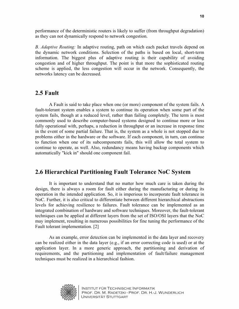
It is important to understand that no matter how much care is taken during the design, there is always a room for fault either during the manufacturing or during its operation in the intended application. So, it is imperious to incorporate fault tolerance in NoC. Further, it is also critical to differentiate between different hierarchical abstractions levels for achieving resilience to failures. Fault tolerance can be implemented as an integrated combination of hardware and software techniques. Moreover, the fault-tolerant techniques can be applied at different layers from the set of ISO/OSI layers that the NoC may implement, resulting in numerous possibilities for fine tuning the performance of the Fault tolerant implementation. [2]
As an example, error detection can be implemented in the data layer and recovery
can be realized either in the data layer (e.g., if an error correcting code is used) or at the application layer. In a more generic approach, the partitioning and derivation of requirements, and the partitioning and implementation of fault/failure management techniques must be realized in a hierarchical fashion.
Institut für Technische Informatik Prof. Dr. M. Radetzki - Prof. Dr. H.-J. Wunderlich
Universität Stuttgart
11
Faults can be characterized by type, source, frequency of occurrence, and impact
at each level in the hierarchy. At the lowest level (physical), it is assumed that a fault will result in a degraded operation of the respective component. If it is not feasible to detect and recover the fault at the lowest level, the fault manifests itself as a local error/failure to the next higher level, where the corresponding Fault tolerant technique is evaluated again relative to performance and cost effectiveness.
The advantage hierarchical approach is that the faults which get propagated from the lower level can dealt at higher levels. In general, the higher in the hierarchy the fault reaches to, the longer it takes to contain and/or recover from the effect of a failure. However there are certain advantages, with respect to area cost and power dissipation, associated to the level in the hierarchy where we try to contain the fault. For example, in Real-time NoC systems, time is the most critical factor for specifying the performance of the Fault tolerance implementation. Therefore, designers have to decide on the effectiveness of a particular method by knowing how quickly faults must be detected, how quickly they have to recover from the occurrence of a fault, how long an error can exist in the NoC infrastructure without impairing/compromising system performance.
Application Level (Application/ Session Layer)
End to End (Network / Transport Layer)
Flit/Packet Level (Data Layer)
Layout & Device Level (Physical Layer)
Faults: Type, Source, Rate, Impact
D/R
D/R
D/R
D/R
Upward fault propagation
&
Increasing detection/recovery
times
Fig. 3: Hierarchical partitioning for fault-tolerant NoC.
Institut für Technische Informatik Prof. Dr. M. Radetzki - Prof. Dr. H.-J. Wunderlich
Universität Stuttgart
12
2.7 Quality-of-Service (QoS) Quality-of-service (QoS) means the levels of guarantees that is given for data transfers. These guarantees are related to timing (minimum throughput, maximum latency, maximum latency jitter), integrity (maximum error rate, maximum packet loss), and packet delivery (in-order or out of- order). There are two approaches for providing quality of service: a) Best effort (BE): In this scheme packets are forwarded as soon as possible but no guarantee is given for latency or throughput. This is the most common approach that is being used. b) Guaranteed throughput (GT): This scheme offers minimum level of transfer capability through network. The fundamental feature of GT is the necessity of a priori knowledge about the traffic load conditions. For example, the network size (link width, topology, buffer sizes) is set to tolerate the estimated worst case conditions. 3. Fault Tolerant NoC Topologies As mentioned before topologies of network, defines how the network nodes are physically connected on the chip and therefore to deal with situation of FAULT during runtime, the topologies must be fault tolerance inclusive. However before we delve deeper, we should first note some characteristics of TOPOLOGIES
1. Diameter: The diameter (D) of a network is the maximum internodes distance, i.e. the maximum number of links that should be traversed to send a message to all nodes along the shortest path. The smaller the diameter of a network, the less time it takes to send a message from one node to the farthest node.
2. Node Degree (Switch Degree): The node degree (ND) is defined as the number of physical channels emanating from a node. This attribute shows the node’s I/O complexity.
3. Bisection: Number of links that are cut to obtain separate network. Bisection bandwidth tells us about Fault tolerance as get two isolated network.
There are many topologies that have been proposed for Network on Chip like Mesh,
Torus, Star, Octagon, etc. Among these topologies, mesh topology has held the attention of the engineers owing to its simplicity. But, mesh topology has long diameter which implies that it has high latency and therefore it has negative effect on communication. So, to reduce the latency, a new topology was proposed namely, Torus topology, nevertheless the simplicity of the mesh topology was retained. In Torus topology, the switches on the edges are connected to the switches on the opposite edges through wrap-around channels. Every switch has five active ports: one of these switches is connected to the local resource while the other four are connected to the closest neighboring switches. The
Institut für Technische Informatik Prof. Dr. M. Radetzki - Prof. Dr. H.-J. Wunderlich
Universität Stuttgart
13
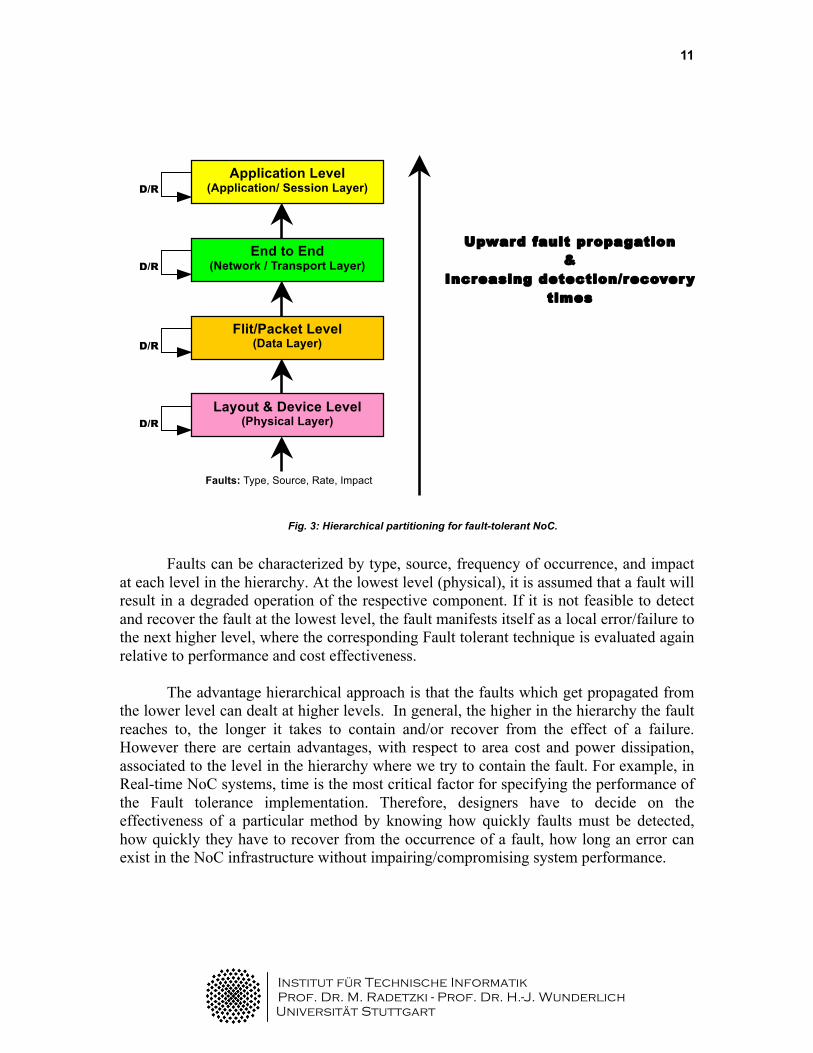
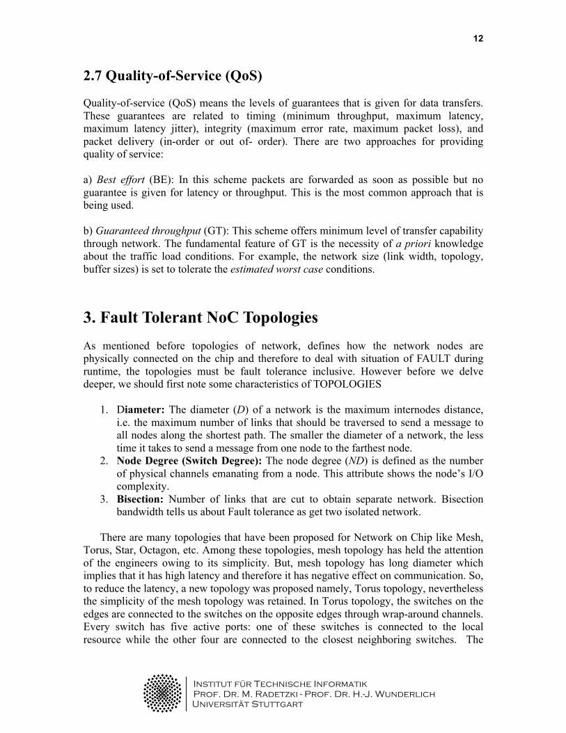
Torus architecture reduces the network diameter, but the long wrap-around connections may result in excessive delay. Some of the most widely used topologies are: 1. Crossbar: In Crossbar topology, every router is connected to some other router which means that NoC is fully connected. This interconnection results into a single crossbar. It does not scale up to large number of Network interfaces. 2. N-dimensional k-ary mesh: This topology, in particular 2-ary mesh, has become been very widely used NoC topology because the routers can be pre-placed in layout and all the links have the same (limited) length. In general, the number of network interfaces per router is usually one, but if required the number can be higher. E.g. QnoC and Nostrum. The area of meshes is in direct proportion to the number of cores, which means that the number of meshes and network interfaces grows linearly with the number of cores. In this arrangement, the average distance between the Network Interfaces is relatively large, which affects power dissipation negatively. Further, they have limited bisection bandwidth and their performance goes down under high load. Therefore, care has to be taken to avoid accumulation of traffic in the center of the mesh and avoid creating a hotspot. 3. d-dimenstional k-ary (fat trees): In this topology, there are d levels in which each router has k children, network interfaces are attached only to the leaves. Due to low concentration of the traffic at the root of the tree, the bisection bandwidth of trees is very low. However, a possible solution is to duplicate the root. This will result in fat trees which have a large bisection bandwidth (and hence performance), but associated area cost also increases. For larger number of nodes, the layout of the fat tree is more difficult, in comparison with meshes or tori.
Fig. 4: Cross Bar Topology
Fig. 5: Butterfly Fat Tree

Institut für Technische Informatik Prof. Dr. M. Radetzki - Prof. Dr. H.-J. Wunderlich
Universität Stuttgart
14
Fault Tolerant topologies 4. Generalized de Bruijn Graph: de Bruijn Graph topology has been there for a while on the minds of the scientist across the world as Fault tolerant NoC topology. In this section, de Brujin graph has been described and its fault tolerant capabilities have been discussed. [5]
A generalized de Bruijn graph, GDB(d,n), has n nodes, where n can be any desired integer value. Further, Generalized de Bruijn graph GDB(d, n) is Hamiltonian. Each two nodes i and j are connected together if they satisfy one of the following equations: (for d=2)
i ≡ 2*j + r (mod n), r=0 or 1 (Eq. 1) j ≡ 2*I + r (mod n), r=0 or 1 (Eq. 2)
GDB(2, n) is called generalized binary de Bruijn graph. A generalized binary de Bruijn graph for n=14 nodes is shown in figure 6. As seen, except four nodes all other nodes have four links. Nodes 0 and 13 have just two links, and Nodes 4 and 9 have three links. The number of links for each node in a generalized de Bruin graph can be determined by the under mentioned theorem. Theorem 1: All nodes in a generalized binary de Bruijn graph have four links, except the following nodes: a) Only two Nodes 0 and n-1 in a GDB(2, n) have two links. b) If n=3k (k is an integer number) then Nodes n/3, 2n/3, (n-3)/3, and (2n-3)/3 have three links. c) If n=3k+1 then Nodes 2(n-1)/3 and (n-1)/3 have three links. d) If n = 3k+2 then Nodes (n-2)/3 and (2n-1)/3 have three links.
A generalized de Bruijn graph possesses many features which makes it a strong contender for implementation of reliable network. The most important feature is the logarithmic relationship between the diameter of a generalized de Bruijn graph and the number of nodes in the graph. The diameter of a generalized de Bruijn graph GDB(d,n) is not greater than logd n.
4.1 NoC Design based on de Bruijn Graph: In order to design a NoC, we have to think of the following:
1. Think of a switch architecture 2. A topology to connect switches together 3. A routing algorithm.

Institut für Technische Informatik Prof. Dr. M. Radetzki - Prof. Dr. H.-J. Wunderlich
Universität Stuttgart
15
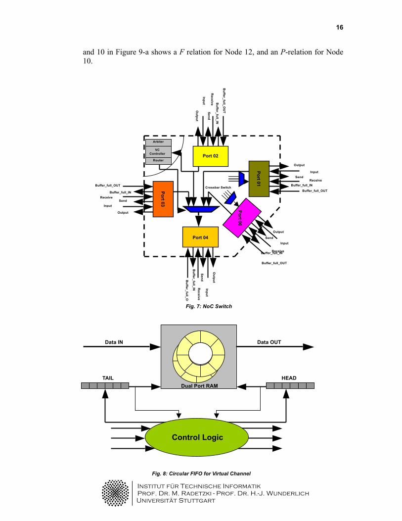
4.1 Switch structure: As mentioned earlier, the switch consists of three parts: I/O ports, a router, and a crossbar switch. The switch used for de Bruijn topology is structural, and consists of five ports each of which is operates independently from other ports and includes a multi channel circular FIFO. Each port is capable to concurrently send/receive data to/from other ports. In a situation when two or more ports want to send data to a port at same point in time, a round-robin arbiter hinders the collusion of data and grants to just one port.
The port which gains the access then begin to send data and other ports
will go in wait mode until this port finishes with sending data. Figure 7 shows the architecture of the simple switch.
4.2 Topology : The de Bruijn graph topology is explained as shown in Figure 9 (c.f.
Figure 6). In order to cover all the links we create two link-disjoint binary spanning trees from de Bruijn graph. So, we use equation 3 and starting from Nodes 0 and n-1(i.e. Node 13), we construct two link-disjoint binary spanning trees of generalized binary de Bruijn graph. These two spanning trees constructed will cover all links and nodes of the corresponding generalized de Bruijn graph. A binary tree is called as complete if the number of nodes n, is a power of 2, else it is incomplete. The two trees are shown in figure 9a and figure 9b.
Further, directed links connecting a node to its parents represent a Parental relation (P-relation); and the directed links that connect a node to its children represent a Filial relation (F-relation). For example, the link between Nodes 12
1
2
3 4
5
6
7
8
9 10
1
1
12
13 0
Fig. 6: De Bruijn Graph (d,n)
Institut für Technische Informatik Prof. Dr. M. Radetzki - Prof. Dr. H.-J. Wunderlich
Universität Stuttgart
16
and 10 in Figure 9-a shows a F relation for Node 12, and an P-relation for Node 10.
Output
Input Send
Receive Buffer_full_IN
Buffer_full_OUT
Port 03
Output
Input S
end R
eceive B
uffer_full_IN
Buffer_full_O
UT
Port 02
Output
Input S
end R
eceive B
uffer_full_IN
Buffer_full_O
UT
Port 04 Output
Input Send
Receive Buffer_full_IN
Buffer_full_OUT
Port 00
Buffer_full_OUT
Output
Input Send
Receive Buffer_full_IN
Port 01 Arbiter
VC Controller
Router
Crossbar Switch
Fig. 7: NoC Switch
Fig. 8: Circular FIFO for Virtual Channel
Control Logic
Dual Port RAM HEAD TAIL
Data IN Data OUT

Institut für Technische Informatik Prof. Dr. M. Radetzki - Prof. Dr. H.-J. Wunderlich
Universität Stuttgart
17
Each link of the tree is labeled as shown in Figure 9. These labels are assigned to each port of the switches in a NoC. The address of each core (connected to a switch in the NoC) is selected based on the code shown below the corresponding leaf node in these trees. Labels 0 and 1 are assigned to all outgoing left and right links in the tree of Figure 9-a, respectively. Labels 1 and 0 are assigned to all outgoing left and right links in the tree of Figure 9-b, respectively. Therefore, using these labels and the link relation (Parental or Filial), each switch can distinguish a specific output port to route an incoming packet.
4.3 Routing: The diameter of a generalized de Bruijn graph has at most a logarithmic
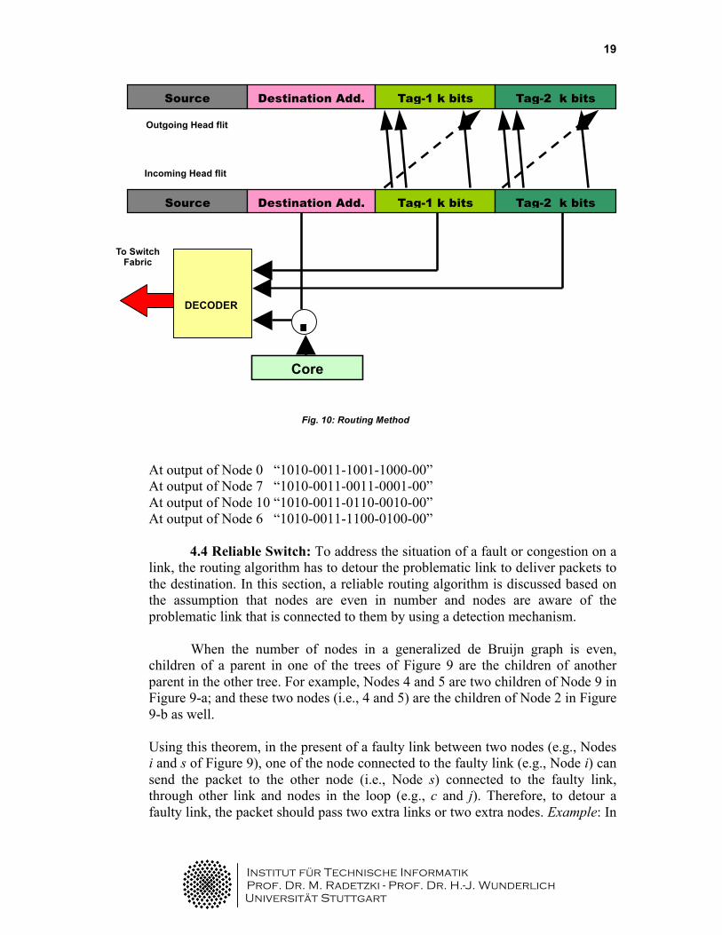
relationship with the number of nodes. Therefore, a simple routing algorithm can be implemented in switches of a NoC, with low area overhead. The routing algorithm uses packet format of wormhole switching as shown in Figure 10. The four fields of the head flit in this figure are: source address, destination address, tags, and flit-type. Flit-type bits determine the head, data, and tail flits. The tag bits that are grouped into two subfields (i.e., Tag-1 and Tag-2) determine the exact route from the source to destination nodes. The network uses source routing algorithm, so the source core generates the tag bits which go through certain minor modifications at each intermediate node along the path to the destination.
When a message arrives at node s, there are two possibilities. First, the message may have to be delivered to the core connected to s, so the switch at s must deliver the packet to that core. On the other hand, if the message is destined for another core, the s must forward the packet to one of its neighbor switches
Fig. 9a: Tree-1
1010
1011 1100 1101 1110 1111
6
10
13
12
11
9
5 4 3 2
8
1 0
7
0
1
0 1
1 0 0 1
0
1
1 0
0
100x
Filial relation
Parental relation
Institut für Technische Informatik Prof. Dr. M. Radetzki - Prof. Dr. H.-J. Wunderlich
Universität Stuttgart
18
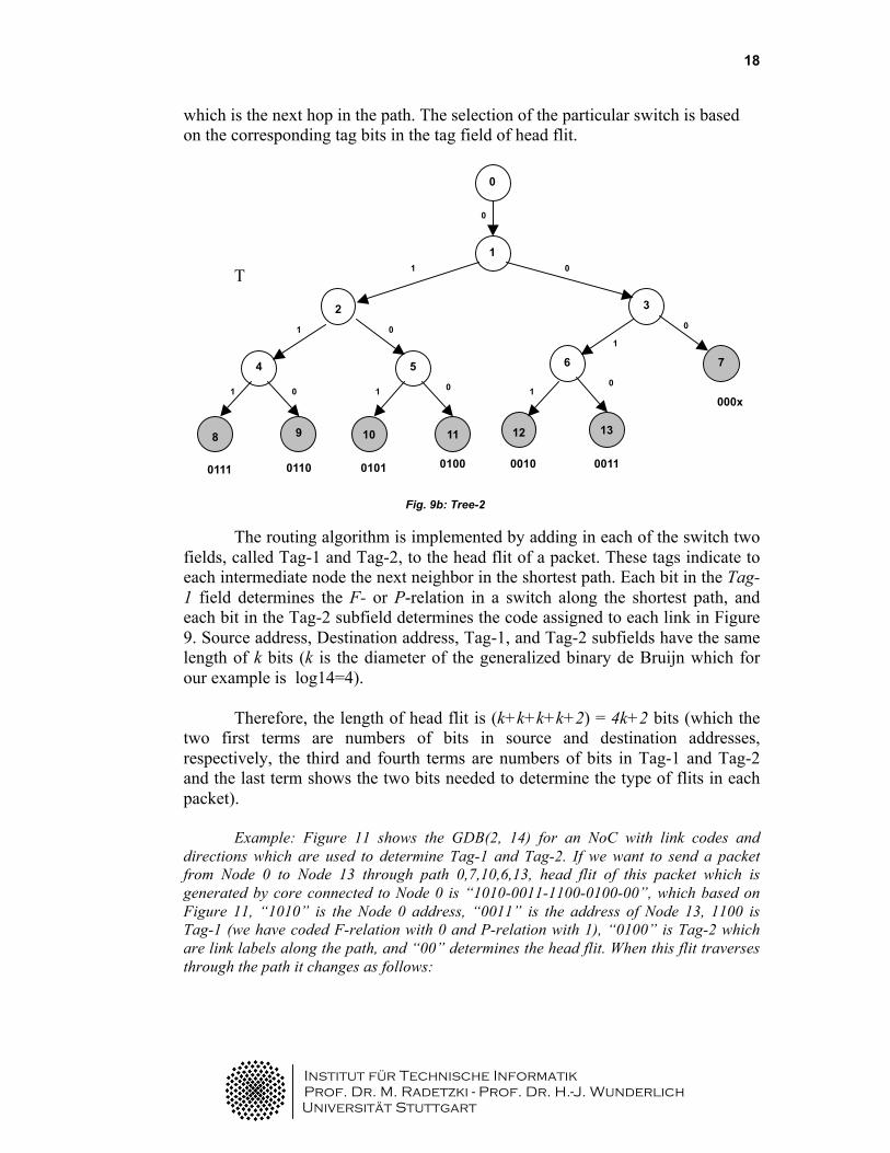
which is the next hop in the path. The selection of the particular switch is based on the corresponding tag bits in the tag field of head flit.
T The routing algorithm is implemented by adding in each of the switch two
fields, called Tag-1 and Tag-2, to the head flit of a packet. These tags indicate to each intermediate node the next neighbor in the shortest path. Each bit in the Tag-1 field determines the F- or P-relation in a switch along the shortest path, and each bit in the Tag-2 subfield determines the code assigned to each link in Figure 9. Source address, Destination address, Tag-1, and Tag-2 subfields have the same length of k bits (k is the diameter of the generalized binary de Bruijn which for our example is log14=4).
Therefore, the length of head flit is (k+k+k+k+2) = 4k+2 bits (which the two first terms are numbers of bits in source and destination addresses, respectively, the third and fourth terms are numbers of bits in Tag-1 and Tag-2 and the last term shows the two bits needed to determine the type of flits in each packet).
Example: Figure 11 shows the GDB(2, 14) for an NoC with link codes and directions which are used to determine Tag-1 and Tag-2. If we want to send a packet from Node 0 to Node 13 through path 0,7,10,6,13, head flit of this packet which is generated by core connected to Node 0 is “1010-0011-1100-0100-00”, which based on Figure 11, “1010” is the Node 0 address, “0011” is the address of Node 13, 1100 is Tag-1 (we have coded F-relation with 0 and P-relation with 1), “0100” is Tag-2 which are link labels along the path, and “00” determines the head flit. When this flit traverses through the path it changes as follows:
0011 0100 0111 0110 0101 0010
6
3
0
1
2
5
11 10 9 8
4
13 12
7 1
0
0 1
1 0
0 1
0 1
1 0
0
000x
Fig. 9b: Tree-2
Institut für Technische Informatik Prof. Dr. M. Radetzki - Prof. Dr. H.-J. Wunderlich
Universität Stuttgart
19
At output of Node 0 “1010-0011-1001-1000-00” At output of Node 7 “1010-0011-0011-0001-00” At output of Node 10 “1010-0011-0110-0010-00” At output of Node 6 “1010-0011-1100-0100-00”
4.4 Reliable Switch: To address the situation of a fault or congestion on a link, the routing algorithm has to detour the problematic link to deliver packets to the destination. In this section, a reliable routing algorithm is discussed based on the assumption that nodes are even in number and nodes are aware of the problematic link that is connected to them by using a detection mechanism.
When the number of nodes in a generalized de Bruijn graph is even, children of a parent in one of the trees of Figure 9 are the children of another parent in the other tree. For example, Nodes 4 and 5 are two children of Node 9 in Figure 9-a; and these two nodes (i.e., 4 and 5) are the children of Node 2 in Figure 9-b as well. Using this theorem, in the present of a faulty link between two nodes (e.g., Nodes i and s of Figure 9), one of the node connected to the faulty link (e.g., Node i) can send the packet to the other node (i.e., Node s) connected to the faulty link, through other link and nodes in the loop (e.g., c and j). Therefore, to detour a faulty link, the packet should pass two extra links or two extra nodes. Example: In
Fig. 10: Routing Method
Source
Address
Destination Add. Tag-1 k bits Tag-2 k bits
Source
Address
Destination Add. Tag-1 k bits Tag-2 k bits
=
Core Address
DECODER
To Switch Fabric
Outgoing Head flit
Incoming Head flit

Institut für Technische Informatik Prof. Dr. M. Radetzki - Prof. Dr. H.-J. Wunderlich
Universität Stuttgart
20
the previous example in which a packet is sent from Node 0 to Node 13, if the link connecting Node 10 to Node 6 is faulty, the new path will be“0→7→1→0→7→3→13”.
Figure 12 shows the relations between parents and children that compose a family. The differences between siblings and parents are 1 and n/2, respectively.
Siblings Relation |S-C| = 1
Siblings
Parent
Parent Relation
|I - j| = n/2
j
c
i
s
Fig. 11: GDB(2,14) with link labels and relations
Fig. 12: Parents, siblings and their relations.
1
2
3 4
5
6
7
8
9 10
1
1
12
13 0
1
0
1
1
1
1
1
1
1
1
1
0
0
0
0 0
0
0
0
0
0
0
0 0
Institut für Technische Informatik Prof. Dr. M. Radetzki - Prof. Dr. H.-J. Wunderlich
Universität Stuttgart
21
5. QRDT Structure and its Network properties
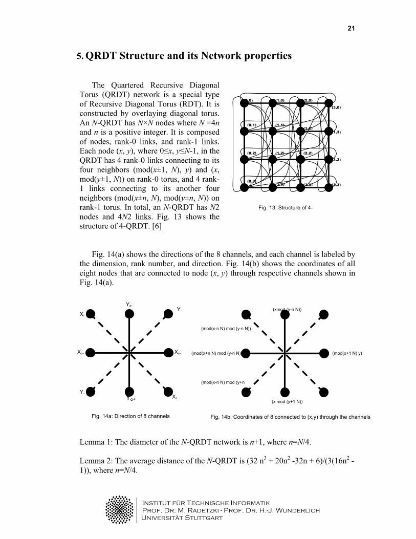
The Quartered Recursive Diagonal Torus (QRDT) network is a special type of Recursive Diagonal Torus (RDT). It is constructed by overlaying diagonal torus. An N-QRDT has N×N nodes where N =4n and n is a positive integer. It is composed of nodes, rank-0 links, and rank-1 links. Each node (x, y), where 0≤x, y≤N-1, in the QRDT has 4 rank-0 links connecting to its four neighbors (mod(x±1, N), y) and (x, mod(y±1, N)) on rank-0 torus, and 4 rank-1 links connecting to its another four neighbors (mod(x±n, N), mod(y±n, N)) on rank-1 torus. In total, an N-QRDT has N2 nodes and 4N2 links. Fig. 13 shows the structure of 4-QRDT. [6]
Fig. 14(a) shows the directions of the 8 channels, and each channel is labeled by
the dimension, rank number, and direction. Fig. 14(b) shows the coordinates of all eight nodes that are connected to node (x, y) through respective channels shown in Fig. 14(a).
Lemma 1: The diameter of the N-QRDT network is n+1, where n=N/4. Lemma 2: The average distance of the N-QRDT is (32 n3 + 20n2 -32n + 6)/(3(16n2 - 1)), where n=N/4.
(0,0)
(3,3) (0,3)
(3,0)
(2,0) (1,0)
(0,2)
(0,1) (1,1) (1,2)
(1,3)
(2,3)
(3,2)
(2,2) (1,2)
(1,3)
Fig. 13: Structure of 4-QRDT
Yo- Y-
Y-
X-
X+
Xo-
Yo+
Xo- (mod(x+1 N) y)
(x mod (y+1 N))
(mod(x-n N) mod (y-n N))
(mod(x+n N) mod (y-n N))
(mod(x-n N) mod (y+n N))
(xmod (y-n N))
Fig. 14a: Direction of 8 channels Fig. 14b: Coordinates of 8 connected to (x,y) through the channels
Institut für Technische Informatik Prof. Dr. M. Radetzki - Prof. Dr. H.-J. Wunderlich
Universität Stuttgart
22
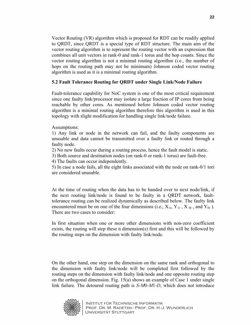
Vector Routing (VR) algorithm which is proposed for RDT can be readily applied to QRDT, since QRDT is a special type of RDT structure. The main aim of the vector routing algorithm is to represent the routing vector with an expression that combines all unit vectors in rank-0 and rank-1 torus and the hop counts. Since the vector routing algorithm is not a minimal routing algorithm (i.e., the number of hops on the routing path may not be minimum) Johnson coded vector routing algorithm is used as it is a minimal routing algorithm. 5.2 Fault Tolerance Routing for QRDT under Single Link/Node Failure Fault-tolerance capability for NoC system is one of the most critical requirement since one faulty link/processor may isolate a large fraction of IP cores from being reachable by other cores. As mentioned before Johnson coded vector routing algorithm is a minimal routing algorithm therefore this algorithm is used in this topology with slight modification for handling single link/node failure. Assumptions: 1) Any link or node in the network can fail, and the faulty components are unusable and data cannot be transmitted over a faulty link or routed through a faulty node. 2) No new faults occur during a routing process, hence the fault model is static. 3) Both source and destination nodes (on rank-0 or rank-1 torus) are fault-free. 4) The faults can occur independently. 5) In case a node fails, all the eight links associated with the node on rank-0/1 tori are considered unusable. At the time of routing when the data has to be handed over to next node/link, if the next routing link/node is found to be faulty in a QRDT network, fault-tolerance routing can be realized dynamically as described below. The faulty link encountered must be on one of the four dimensions (i.e., X1r, Y1r , X 0r , and Y0r ). There are two cases to consider: In first situation when one or more other dimensions with non-zero coefficient exists, the routing will step these n dimension(s) first and this will be followed by the routing steps on the dimension with faulty link/node. On the other hand, one step on the dimension on the same rank and orthogonal to the dimension with faulty link/node will be completed first followed by the routing steps on the dimension with faulty link/node and one opposite routing step on the orthogonal dimension. Fig. 15(a) shows an example of Case 1 under single link failure. The detoured routing path is S-M0-M1-D, which does not introduce
Institut für Technische Informatik Prof. Dr. M. Radetzki - Prof. Dr. H.-J. Wunderlich
Universität Stuttgart
23
X X S
M1
D
M0 M1 S
D
M2 M3
M4
X
Fault Link Original Path New path
Case A Case B
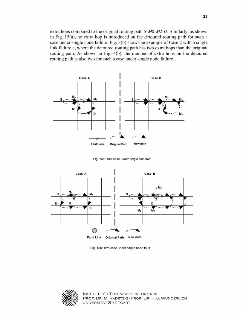
extra hops compared to the original routing path S-M0-M2-D. Similarly, as shown in Fig. 15(a), no extra hop is introduced on the detoured routing path for such a case under single node failure. Fig. 3(b) shows an example of Case 2 with a single link failure e, where the detoured routing path has two extra hops than the original routing path. As shown in Fig. 4(b), the number of extra hops on the detoured routing path is also two for such a case under single node failure.
X X
S
M1
D
M0 M3 S
D
M2
M0
Fault Link Original Path New path
Case A Case B
X X
M2
X
X X
M1
Fig. 15b: Two case under single node fault
Fig. 15a: Two case under single link fault

Institut für Technische Informatik Prof. Dr. M. Radetzki - Prof. Dr. H.-J. Wunderlich
Universität Stuttgart
24
4. Conclusion
Network on chip offers a lucrative solution to the communication problems faced by the System on Chip. However, the system performance can still be impeded by network congestion, fault at links or node faults. Since, the performance of topology is the performance of NoC, so it is important to find a topology that is capable of handling these fault situations.
In this report, I have discussed the importance of Fault Tolerant topologies for NoC.
We have addressed to the situation of fault that might occur in the chip during manufacturing or during its operation in the real world applications. In order to do that we talk about fault tolerance for topology so that the time and power consumption to remove the possible effects of fault is less. Various topologies that are presently in use have been presented keeping focus on fault tolerance. A special mention of de Bruijn graph as a fault tolerant topology has been done to demonstrate how topology can be helpful in increasing the fault tolerance of the NoC. Also, Quartered recursive diagonal torus has also been discussed briefly.
Institut für Technische Informatik Prof. Dr. M. Radetzki - Prof. Dr. H.-J. Wunderlich
Universität Stuttgart
25
References [1] Nguyen, H.N. and Ngo, V.D. and Choi, H.W., “Assessing Routing Behavior on On-Chip-Network, International Conference on Computer Engineering and Systems, 2006. Pages 62-65, 2006. [2] Cristian Grecu, Lorena Anghel, Partha P. Pande, André Ivanov, Resve Saleh, “Essential Fault-Tolerance Metrics for NoC Infrastructures, 10th Euromicro Conference on Digital System Design Architectures, Methods and Tools, (DSD 2007) [3] Salminen, E. and Kulmala, A. and Hamalainen, T.D., “Survey of Network-on-chip Proposals”, White Paper, OCP-IP, March 2008. [4] Mirza-Aghatabar, M. and Koohi, S. and Hessabi, S. and Pedram, M., “An Empirical Investigation of Mesh and Torus NoC Topologies Under Different Routing Mechanism”, 10th Euromicro Conference on Digital System Design Architectures, Methods and Tools, 2007. Pages 19-26, 2007. [5] Hosseinabady, M. and Kakoee, MR and Mathew, J. and Pradhan, DK , “Reliable network-on-chip based on generalized de Bruijn graph”, IEEE International High Level Design Validation and Test Workshop, HLVDT 2007. Pages 3-10, 2007. [6] Tan, X. and Zhang, L. and Neelkrishnan, S. and Yang, M. and Jiang, Y. and Yang, Y., “Scalable and Fault Tolerant Network on Chip Design using the Quartered Recursive Diagonal Torus Topology”, Proceedings of the 18th ACM Great Lakes symposium on VLSI, Pages 309-314, 2008.