universiti putra malaysia design and fabrication of...
TRANSCRIPT
UNIVERSITI PUTRA MALAYSIA
DESIGN AND FABRICATION OF AUTONOMOUS ENTERTAINMENT MOBILE ROBOT
ASNOR JURAIZA BINTI DATO' HJ. ISHAK
FK 2003 41
DESIGN AND FABRICATION OF AUTONOMOUS ENTERTAINMENT MOBILE ROBOT
Dy
ASNOR JURAIZA DINTI DATO' HJ. ISHAK
Thesis Submitted to the School of Graduate Studies, Universiti Putra Malaysia, in Fulfilment of Requirements for the
.
Degree of Master of Science
September 2003

Dedicated to my parents, Data' Hj. Ishak Idris and Datin Hjh. Asmah Md Rashid,
my husband and daughter, Aziz Kamal and Anis Amalina Aziz,
and my dearest brothers and sister .....
...... With Love ..... .
11
Abstract of thesis presented to the Senate ofUniversiti Putra Malaysia in fulfilment of the requirement for the degree of Master of Science
DESIGN AND FABRICATION OF AUTONOMOUS ENTERTAINMENT MOBILE ROBOT
By
ASNOR JURAIZA BINTI DATO' HJ. ISHAK
September 2003
Chairman : Associate Professor Ishak bin Aris, PhD.
Faculty : Engineering
Mobile robots are already widely used for surveillance, inspection and transportation
tasks. An emerging technology with enormous potential is the entertainment mobile
robot. Sony Corporation has developed a Sony dog known as Sony's Aibo that
cannot speak but can chase a ball, lie down, sit and wag its tail. The robot must
operate in a safe and friendly manner, avoiding obstacles and posing no risk to
human in its vicinity. The scenario in Malaysia is that not many entertainment
mobile robot has been developed because generally, Malaysians are content with
their role as a user rather than a developer . . In order to achieve the objectives of the
"Vision 2020", Malaysia should produce more scientists and developers in various
areas. The best and most effective way of learning and stimulating interest in
entertainment robot is through contests. Therefore, Sirim Berhad and the Ministry of
Education have organized the Robot Games Festival or Robofest 2002 to encourage
researchers, lecturers and students to design and develop robotic systems.
The main objective of this project is to design and develop an entertainment mobile
robot that can place as many beach balls as possible into the cylinder tubes within 3
111
minutes. In the festival, the robot can be manual and/or automatic. The manual robot
must not touch Kinabalu Zone (Appendix B l ) and starts only at 'Start Zone A'.
Meanwhile, the automatic robot can touch and enter the entire area of the game field
and starts at 'Start Zone B' in the Kinabalu Zone.
The development of the entertainment mobile robot consists of hardware and
software development. The hardware development is divided into two parts namely,
mechanical design and electrical design. The mechanical design involves a platform
module, a storage module and an arm manipulator module. While, electrical design
includes a power supply module, a sensing system, a control panel, a DC motor
driver and a programming logic controller. The software development is required to
develop the programming of this robot and the software used is FPWIN GR PLC.
The design of the proposed robot is based on the Cylindrical coordinate concept
known as Y -Z-9 coordinate. In the contest, two strategies plan of motion are applied
that are the I motion and the L motion. Therefore, the strategy should be selected
before the match starts. The I motion only involves Y-axis motion or straight motion
while L motion requires Y-axis, Z-axis (turn left or right) and 9-axis motion
(rotation).
Based on the result testing and the contest that took place, the entertainment mobile
robot is found to be operating according to its contest motion plan.
IV
Abstrak tesis dikemukakan kepada Senat Universiti Putra Malaysia sebagai memenuhi keperluan untuk Ijazah Master Sains
REKABENTUK DAN FABRIKASI ROBOT HIBURAN
Oleh
ASNOR JURAIZA BINTI DATO' HJ. ISHAK
September 2003
Pengerusi : Profesor Madya Ishak bin Aris, PhD.
Fakulti : Kejuruteraan
Robot hiburan secara meluasnya telah digunakan dalarn bidang pengawasan,
pemeriksaan dan pengangkutan. Robot hiburan mempunyai pontensi yang tinggi
dalarn bidang teknologi. Syarikat Sony telah membina sebuah robot anjing Sony
yang dikenali sebagai Sony Aibo dimana robot ini tidak boleh bercakap tetapi
mempunyai keupayaan memegang bola, baring dan duduk serta menggerakan
ekomya. Robot harus dikendalikan secara selarnat dan berkeadaan baik bagi
mengelakkan halangan dan risiko pada persekitaran manusia. Senario di Malaysia
secara umumnya memperlihatkan bahawa tidak banyak pembinaan robot hiburan
keranan dasar dan peraturan kerajaan yang hanya bertindak sebagai pengguna
daripada bertindak sebagai pengusaha. Sebagai panduan untuk mencapai sasaran
"Wawasan 2020", Malaysia seharusnya melahirkan lebih rarnai saintis dan
pengusaha dalarn pelbagai bidang. lalan terbaik dan berkesan untuk mempelajari dan
menaruh minat dalarn bidang robot hiburan adalah melalui pertandingan. Untuk yang
demikian, Sirim Berhad dan Kementerian Pendidikan telah menganjurkan satu
kejohanan Pesta Pertandingan Robot 2002 untuk menggalakkan penyelidik,
pensyarah dan pelajar merebentuk dan membina sistem robotik.
v

Objektif utama projek ini ialah untuk merekabentuk dan membina sebuah robot
hiburan yang membolehkan ianya memasukkan bola pantai sebanyak mungkin ke
dalam tiub silinder dalam masa 3 minit. Dalam pertandingan ini, robot ini boleh
dikawal samada secara manual ataupun automatik. Robot manual tidak boleh
memasuki dan menyentuh Zon Kinabalu (Apendik Bl) dan perIu bermula di 'Zon
Permulaan A'. Manakala, robot yang dikawal secara automatik dibolehkan
memasuki dan menyentuh kawasan pertandingan dan bermula di 'lon Permulaan B'
dalam kawasan Zon Kinabalu.
Pembinaan robot hiburan ini melibatkan pembinaan perkakasan dan perisian.
Pembinaan perkakasan dibahagikan kepada dua kategori iaitu rekabentuk mekanikal
dan rekabentuk elektrik. Rekabentuk mekanikal melibatkan rekabentuk modul
planta, modul simpanan dan modul lengan robot. Manakala rekabentuk elektrik
merangkumi modul bekalan kuasa, sistem pengesan, panel kawalan, motor arus terus
dan kawalan pengaturcara logik. Pembinaan perisian dalam robot ini diperIukan
dengan membina satu sistem pengaturcara menggunakan perisian FPWIN GR PLC.
Rekabentuk robot yang diperlukan ini adalah berdasarkan kepada konsep kordinat
berbentuk silinder yang dikenali sebagai kordinat Y -Z-9. Dalam pertandingan ini,
dua rancangan strategi pergerakan diaplikasikan iaitu pergerakan I dan pergerakan L.
Walaubagaimanapun, strategi harus ditentukan sebelum pertandingan bermula.
Pergerakan I hanya melibatkan pergerakan paksi Y atau pergerakan lurus manakala
pergerakan L melibatkan paksi Y, paksi Z (pusing kekiri dan kekanan) dan paksi e
(putaran).
VI

Berdasarkan kepada keputusan ujian dan keputusan ketika pertandingan, robot
hiburan ini dapat beroperasi seperti keperluan dalam pertandingan tersebut.
Vll

ACKNOWLEDGEMENTS
I could not have accomplished this project without the help of.Allah S.W.T. Thanks
to Allah S.W.T that I can complete my project successfully.
First and foremost, I would like to express my gratitude to my project supervisor,
Associate Professor Dr. Ishak Aris for his valuable advice, guidance and willingness
to share his expertise knowledge.
I would also like to thanks my project co-supervisor, Dr. Samsul Bahari Mohd Noor
and Associate Professor Dr. Napsiah Ismail for their valuable opinions and guidance
and checking the accuracy of my entire project.
I have also indebted to the help of Hj. Noorfaizal Dato' Hj. Yidris and Mr. Danny
Lim of Intellogic Technology Sdn Bhd for their various ideas, suggestions and
valuable aid to carry out this project.
Special thanks to my loves ones, Dato' Hj. Ishak Idris and Datin Hjh. Asmah Md
Rashid, my beloved husband and daughter, Aziz Kamal and Anis Amalina Aziz, my
dearest brothers and sister, my dearest friends, Mashida Sakrani, Huda Rameli,
lzadora Mustafa, Siti Fatimah Sadikon and anyone for their patience, encouragement
and continuous support.
.. .
Vlll

I certify that an Examination Committee met on 4 September 2003 to conduct the final examination of Asnor Juraiza Dato' Hj. Ishak on her Master of Science thesis entitled "Design And Fabrication Of Autonomous Entertainment Mobile Robot" in accordance with Universiti Pertanian Malaysia (Higher Degree) Act 1980 and Universiti Pertanian Malaysia (Higher Degree) Regulations 1 98 1 . The Committee recommends that the candidate be awarded the relevant degree. Members of the Examination Committee are as follows:
Sudhanshu Shekhar Jamuar, Ph.D. Professor Faculty of Engineering Universiti Putra Malaysia (Chairman)
Ishak Aris, Ph.D. Associate Professor Department of Electrical and Electronics Engineering Faculty of Engineering Universiti Putra Malaysia (Member)
Samsul Bahari Mohd Noor, Ph.D. Lecturer Department of Electrical and Electronics Engineering Faculty of Engineering Universiti Putra Malaysia (Member)
Napsiah Ismail, Ph.D. Associate Professor Department of Mechanical and Manufacturing Engineering Faculty of Engineering Universiti Putra Malaysia (Member)
�L1HJLAT ALI, Ph.D. ProfessorlDepu Dean School of Graduate Studies Universiti Putra Malaysia
IX

This thesis submitted to the Senate of Universiti Putra Malaysia and was accepted fulfilment of the requirement for the degree of Master of Science. Members of the Supervisory Committee are as follows:
Ishak Aris, Ph.D. Associate Professor Department of Electrical and Electronics Engineering Faculty of Engineering Universiti Putra Malaysia (Chairman)
Samsul Bahari Mohd Noor, Ph.D. Lecturer Department of Electrical and Electronics Engineering Faculty of Engineering Universiti Putra Malaysia (Member)
Napsiah Ismail, Ph.D. Associate Professor Department of Mechanical and Manufacturing Engineering Faculty of Engineering Universiti Putra Malaysia (Member)
•................................•
AINI IDERIS, Ph.D. ProfessorlDean School of Graduate Studies Universiti Putra Malaysia
Date 2 5 FEB 2004
x
DECLARATION
I hereby declare that the thesis is based on my original work except for quotations and citations, which have been duly acknowledged. I also declare that it has not been previously or concurrently submitted for any other degree at UPM or other institutions.
���� ....... ........•.............•. :.� .......•...................
ASNOR JURAIZA DINTI DATO' HJ. ISHAK
Date: � J.A N :l-COl;
xi

TABLE OF CONTENTS
DEDICATION ABSTRACT ABSTRAK ACKNOWLEDGEMENTS APPROVAL SHEETS DECLARATION LIST OF TABLES LIST OF FIGURES LIST OF ABBREVIATIONS LIST OF SYMBOLS
CHAPTER
1
2
INTRODUCTION 1.1 Introduction 1.2 Objectives 1.3 Project Overview 1.4 Features of the Entertainment Mobile Robot 1.5 Organization
LITERATURE REVIEW 2.1 Introduction of Robot Festival Contest (ROBOCON) 2.2 Research on Mobile Robot 2.3 Selected Components used for the Propose Robot
2.3 .1 Photoelectric Sensors 2.3.2 Inductive Proximity Sensor 2.3.3 Incremental Rotary Encoders 2.3 .4 Solenoid 2.3.5 Relays 2.3.6 Direct Current (DC) Motor 2.3.7 Stepper Motors 2.3.8 Spur Gear and Worm Gear 2.3.9 Springs 2.3.10 Robot Controller and Programming Software
2.3.8.1 Programmable Logic Controller (PLC) 2.3 .8.2 Basic Structure of PLC 2.3.8.3 Types of Inputs and Outputs 2.3.8.4 Advantages and disadvantages of PLC
2.4 PLC Programming 2.5 Summary of Literature Review
Page
11 III v viii IX Xl xv XVI XX xxi
1.1 1.2 1.3 1.9 1.10
2.1 2.3 2.8 2.8 2.10 2.10 2.11 2.12 2.13 2.15 2.16 2.19 2.20 2.21 2.21 2.23 2.24 2.25 2.26
xu
3 METHODOLOGY 3.1 Overview 3 . 1 3 .2 Mechanical Design 3.2
3 .2.1 Platform Module 3.5 3 .2. 1 . 1 Design of the Y-axis motion 3.8 3 .2. 1 .2 Design of the Z-axis motion 3.11 3 .2. 1 .3 Design of the a-axis motion 3 . l6
3 .2.2 Storage Module 3.21 3 .2.3 Arm Manipulator Module 3.23
3.3 Electrical Design and Development 3.32 3 .3 .1 Power supply module management 3.33 3.3.2 Permanent -magnet DC Motor 3.35 3.3.3 Sensing System 3.38 3 .3 .4 Control Panel 3.40 3 .3.5 Circuit Protection 3.43 3 .3.6 Programmable Logic Control 3.44
3 .4 Software Development 3.46 3 .4. 1 Flow chart and ladder diagram design 3.47 3 .4.2 NAIS PLC Programming Development Software 3.61 3 .4.3 Creating and Editing the Program 3.62 3 .4.4 Checking and Compiling the Program 3.63 3 .4.5 The Input and Output Port Indication 3.64
3 .5 System Integration 3.65
4 RESULT AND DISCUSSION 4.l Introduction 4. l 4.2 Platform Module 4.1
4.2.1 Y-axis Motion 4.2 4.2.1.1 Test Conducted to the Y-axis motion 4.4
4.2 . 1 .1.1 Y-axis direction accuracy test 4.4 4.2.1.1.2 Timing accuracy test for Y-axis 4.6
4.2.2 Z-axis Motion 4.7 4.2.2. 1 Test Conducted to the Z-axis motion 4.9
4.2.2.1.1 Sensor detection test for Z-axis 4.9 4.2.3 a-axis Motion 4.11
4.2.3.1 Test Conducted to the a-axis Motion 4.12 4.2.3.1. 1 Repeated positioning test for
a-axis Motion 4.13 4.3 Storage Module 4.14
4.3.1 Test Conducted to the storage module 4.16 4.3.1. 1 Divider positioning test 4. 1 6 4.3 . 1 .2 Cylinders positioning test 4.16
4.4 Arm Manipulator 4. l 7 4.4.1 Test Conducted to the Arm Manipulator Module 4.20
4.4.1. 1 Solenoids Test 4.20 4.4.1.2 Adjustment of the level barrier 4.22
4.5 Permanent Magnet DC Motor Drivers 4.23 4.6 System Control Software 4.25
XIll

5 CONCLUSION 5.1 System Integration
5.1.1 Cost of the Project 5.2 The Real Game 5.3 Conclusion 5.4 Recommendation
REFFERENCES
APPENDIXES Appendix A: Mechanical Drawing of the proposed robot Appendix B: Game field layout Appendix C: Programmable Logic Controller (PLC) programming Appendix D: Design chart Appendix E: Electrical components
BIODATA OF THE AUTHOR
5.1 5.3 5.3 5.5 5.6
R.1
A. l A.2 A.4 A.8 A. 13
B.1
XIV

LIST OF TABLES
Page
Table 3.1: Inputs and outputs mapping of the system 3 .64
Table 4.1: The range measured for each repeated movement 4.5
Table 4.2: The testing duration of the trial game 4.7
Table 4.3: Test the sensor functioning based on setting distance 4.10
Table 4.4: The testing result ofthe motor positioning in 9-axis 4. 1 3
Table 4.5: The amount of the discharge balls based on cylinder rotation 4.17
Table 4.6: The operation status of the hooks and plunger solenoids 4.22
Table 4.7: Accuracy of the barrier level 4.7
Table 4.8: The testing result of the motor driver 4.25
Table 4.9: Type and function of relays 4.25
Table 4.10: The 110 mapping of the FPO 4.26
Table 5.1: Robot specification 5.2
Table 5.2: Cost of the project 5.3
xv

LIST OF FIGURES
Page
Figure 1.1: Development Process of the Proposed Robot 1.3
Figure 1.2: Design Process of the Proposed Robot 1.6
Figure 1.3: Mechanical Design of the Entertainment Mobile Robot 1.7
Figure 1.4: Electrical Design of the Mobile Robot 1.8
Figure 1.5: Software Development of the Robot 1.8
Figure 2.1: Robot Soccer 2.5
Figure 2.2: Three Type of Reflective Surface for Photoelectric Systems 2.9
Figure 2 .3 : Internal Operation of Incremental Encoder 2.10
Figure 2.4: A Solenoid 2.12
Figure 2.5(a) and (b): Normally Open and Normally Clos�d Relay 2.13
Figure 2.6: Basic Components ofa Simple DC Motor 2.14
Figure 2.7: Spur Gears 2.17
Figure 2.8 : Worm Wheel Attach to Worm Gear 2.18
Figure 2.9: Spring 2.20
Figure 2.10: Structure of Programmable Logic Controller 2.22
Figure 2.11: Type of Input and Output Signal 2.23
Figure 2.12: Signal from Switch or Sensors 2.23
Figure 3 .1: Project Activities of the Proposed Robot 3.3
Figure 3 .2 : The I Motion and L Motion 3 .4
Figure 3 .3 : The Front Wheels of Vehicle Frame 3.5
Figure 3 .4: Technical Drawing of the Platform Module 3 .7
Figure 3 .5 : The Driver Motor for Y-axis Movement 3 .8
Figure 3 .6 : The 2D View of the Proposed Robot 3.9
XVI
Figure 3.7: The Jack Stand Couples with the Spur and Worm Gear 3.12
Figure 3.8: The motor,gears,shaft and encoder arrangement of the a-axis motion 3.17
Figure 3.9: Storage Module 3.21
Figure 3.10: The Three Modules of the Mechanical Design 3.22
Figure 3.11: Technical Drawing of the Storage Module
Figure 3.12: Technical Drawing of the Arm Manipulator
Figure 3.13: The Arm Manipulator Module
Figure 3.14: Distribution of Power Supply
Figure 3.15: Power Supply Management
3.28
3.31
3.32
3.33
3.34
Figure 3.16: Wiring diagram of relay and DC motor for the connection to PLC 3.36
Figure 3.17: The Schematic Diagram of the DC Motors and Relays 3.37
Figure 3.18: Wiring Diagram of Switches to the PLC 3.39
Figure 3.19: Typical Wiring Diagram of Photoelectric Sensor to the PLC 3.40
Figure 3.20: Technical Drawing of the Control Panel Box 3.41
Figure 3.21: Wiring Connection of the Robot to the PLC 3.42
Figure 3.22: Layout of the Electronic Devices Inside Control Panel 3.43
Figure 3.23: Inputs and Outputs Devices are Connected to the PLC Com ports 3.46
Figure 3.24: The Flow Chart of the Software Development 3.55
Figure 3.25: The FPWIN GR Programming Edit Window 3.61
Figure 3.26: Select the PLC Type 3.62
Figure 3.27: The Checking Result of the Program
Figure 4.1: The Driver Motor is Coupled with an Encoder
Figure 4.2: The Two Wheel is Fixed with Steel Bar
Figure 4.3: The Testing Field for Y-axis Direction
Figure 4.4: The Jack Stand and Marker
3.64
4.3
4.3
4.5
4.8
XVll
Figure 4.5: The Photoelectric Sensor 4.9
Figure 4.6: The Correlation of the Output Voltage Sensor and Setting Distance 4.11
Figure 4.7: The Start Zone B Position 4.12
Figure 4.8: The Storage Module 4.15
Figure 4.9: The View of Anns in Home Position
Figure 4.10: The View of Arms After the Hooks are Released
Figure 4.11: A pair of Shock Absorber
4.18
4.19
4.19
Figure 4.12: The Solenoid in Released Position 4.20
Figure 4.13: The Hook and Plunger Solenoid (upper position) in Home Position 4.21
Figure 4.14: The Testing of Plunger Positioning 4.21
Figure 4.15: The Level of Barrier in Various Angel
Figure 4.16: The Testing of Z-axis and a-axis Motor
Figure 4.17: Stop and Reset Function
Figure 4.18: Manual Mode Function
Figure 4.19: Automatic Mode Function
Figure 4.20: Y-axis Motion when Switch left/right Off Function
Figure 4.21: Whole Robot Rotate 90 Function
Figure 4.22: Y-axis Motion when Switch left/right On Function
Figure 4.23: Whole Robot Rotate 270 Function
Figure 4.24: Stop and Reset Function
Figure 4.25: I Motion Function
Figure 4.26: Cylinders Rotation Function
Figure 4.27: Combination of! Motion and Cylinders Rotation
Figure 4.28: Y-axis Forward Mode Function
Figure 4.29: Z-axis Forward Mode Function
4.23
4.24
4.26
4.26
4.27
4.27
4.27
4.27
4.27
4.28
4.28
4.28
4.29
4.30
4.30
XVlll
Figure 4.30: Z-axis Reverse Mode Function 4.30
Figure 4.31: Arms Module Mode Function 4.30
Figure 4.32: a-axis Forward Mode Function 4.30
Figure 4.33 : Storage Module Mode Function 4.31
Figure 5 . 1 : The Mechanical Structure of the Entertainment Mobile Robot 5 . 1
XIX

AC
BISMARC
CARL
CPU
DC
EEROM
VO
LED
MCSM
NCSU
PLC
RBMS
ROBOCON
SIRIM
TISOFT
VA
LIST OF ABBREVIATIONS
Alternative current
Biologically Inspired System for Map-based Autonomous Rover Control
Construction Automation and Robotics Laboratory
Centre processing unit
Direct current
Erasable programmable read-only memory
Input and output
Light-emitting diode
Mobile Camera Space Manipulation
North Carolina State University
Programmable Logic Controller
Robotic Bridge Maintenance System
Robot Festival Contest
Standards and Industrial Research Institute of Malaysia
Texas Instruments software
Volt amperes
xx
LIST OF SYMBOLS
T Torque
J Inertia
t Time
ro Angular velocity
g Gravity constant
WL Weight of the load
WG Weight of the gear
RL Radius of load wheel
Ro Radius of gear
NG Number of teeth gear
r Radius of gear
rpm Revolutions per minute
d Diameter of gear
m Meter
XXI
1.1 Introduction
CHAPTERl
INTRODUCTION
Robots are very useful in the manufacturing industry to perform tasks like welding,
grinding and part assembly. Nowadays, mobile robots have begun to achieve the
dreams of researchers. Mobile robots make our life easier and safer in many ways
such as sea exploration, planet discovery, dangerous military and police missions, as
well as being a new type of entertainment (Jones, et aI., 1999).
In Malaysia, many industrial companies are not interested to participate in the
research and development of robots. Lack of financial support and involvement by
researchers and students worse the situation. However, the recent success by Honda's
Asimo and Sony's Aibo has changed people's perception. They make use of the
development of robots in the world of entertainment.
Sirim Berhad believes that the best and most effective way of learning and
stimulating interest in robotics is through contests. The proposed project was
designed and fabricated to participate in the first Malaysia Robot Games Festival or
Robofest 2002. It is an annual event to promote robotic and artificial intelligent fields
and hold activities such as robot contests, exhibitions, demonstration, forum and
semmar.
1.1

The contest (Robofest 2002) was held on 5th of May 2002 with SIRIM Berhad as the
organizer. In the contest, only two types of machines were allowed; the automatic
and manual machines. The participants were among university and polytechnic
students. Each team had 4 members that were made up of 3 students and 1 instructor
or lecturer. The layout of the game field is attached in Appendix BI.
1.2 Objectives
The main objective of this project is to develop an entertainment mobile robot that
can place as many beach balls as possible into the cylinder tubes within 3 minutes.
In order to achieve the main objective, the following works must be carried out. They
involve the development of:
• the platform module
• the storage module
• the robot arm manipulator module
• the DC motor driver
• the sensing system
• the power supply module
• the controller
• the programming design.
1.2
1.3 Project Overview
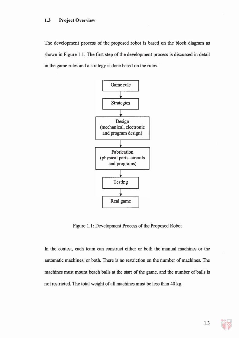
The development process of the proposed robot is based on the block diagram as
shown in Figure 1 . 1 . The first step of the development process is discussed in detail
in the game rules and a strategy is done based on the rules.
Game rule
Design (mechanical, electronic and program design)
Fabrication (physical parts, circuits
and programs)
Real game
Figure 1 . 1 : Development Process of the Proposed Robot
In the contest, each team can construct either or both the manual machines or the
automatic machines, or both. There is no restriction on the number of machines. The
machines must mount beach balls at the start of the game, and the number of balls is
not restricted. The total weight of all machines must be less than 40 kg.
1.3