university of notre dame tribological investigation of the carbon- carbon composite brake system...
DESCRIPTION
University of Notre Dame Outline Introduction Three-Dimensional Thermoelastic Rough Surface Contact Model for Isotropic Materials Three-Dimensional Asperity Contact Model for Anisotropic Materials with General Boundary Condition Future WorkTRANSCRIPT

University of Notre Dame
Tribological Investigation of the Carbon-Carbon Composite Brake System
Ling HeAdvisor: Timothy C Ovaert
University of Notre DameOct. 19th, 2006

University of Notre Dame
Objection of My Research• Aircraft Brake System Control
• Racing Automobile Brake System Design

University of Notre Dame
Outline Introduction
Three-Dimensional Thermoelastic Rough Surface Contact Model for Isotropic Materials
Three-Dimensional Asperity Contact Model for Anisotropic Materials with General Boundary Condition
Future Work

University of Notre Dame
Introduction

University of Notre Dame
Contact Problem for Elastic Material
1 2 0, 0 ( )z i z i i i i cu u h P i
1 2 0, 0 ( )z i z i i i i cu u h P i
Governing Equation:
( )
s
ii
P P
1 2i i ih S S
1 2i
1 2
z1 z2
1 2
P : total external load = + : total approach
+ : total deflectionS = S + S : initial gapzu u u

University of Notre Dame
Total area: A=∑Ai
Three-Dimensional Asperity Contact Model
Analysis Flowchart Discretize the brake surface region
Read characteristic data for each separate region
Solve 3D rough surface thermoelastic problem using
CGM technique.
Obtain subsurface stress/strain…etc. based on
contact pressureAnalysis and graph the result
Ai

University of Notre Dame
Rough Surface Contact
is iu
c s
OD
node
0P
0
i
c
s
P : total external load : total approach : total deflection
s : initial gap : contact area : seperate area
Curve O : origional profileCurve D : deformed profile
iu

University of Notre Dame
Why Need Analytical Solution
Numerical Method(FEM, BEM, etc)
Analytical Method
Problem Type Complex Case Simple CaseResult Transient/Steady State Steady State
Solving Time Slow Relatively FasterAccuracy Good Relatively worse
Can numerical methods handle rough contact problem? No!

University of Notre Dame
Three-Dimensional Thermoelastic Rough Surface Contact Model for Isotropic Materials

University of Notre Dame
Deflection ( ) of B when pressure is applied at A (elastic effect)
3D Thermoelastic Asperity Contact Model for Isotropic Materials
Normal pressure applied to circular region
)()()(
)()()(ln)(
)()()()()()(ln)(
)()()(
)()()(ln)(
)()()()()()(ln)(
1
2/122
2/122
2/122
2/122
2/122
2/122
2/122
2/122
2
axbyax
axbyaxby
axbybyaxbybyax
axbyax
axbyaxby
axbybyaxbybyax
puE z
pdxdyzu
x=(x(B)-x(A)); y=(y(B)-y(A));a=dx/2;b=dy/2;
zu
z
AB
y [m]x [m]
[m]
zu
pdxdyzu

University of Notre Dame
3D Thermoelastic Asperity Contact Model for Isotropic Materials
Normal pressure applied to circular region
Deflection (uz) of B when pressure is applied at point A (thermal effect).
' ln))((ln))(( ln))((ln))((
tantan2
)(
tantan2
)(
tantan2
)(
tantan2
)()(2
43
21
112
112
112
112
Crybxarybxarybxarybxa
ybxa
ybxayb
ybxa
ybxayb
xayb
xaybxa
xayb
xaybxaABCDu
ch z
z
AB
ω
x [m]y [m]
[m]zu
zu
pdxdypdxdy
ω : rotational velocity (rad/s)r1,r2,r3,r4 : the distance from B to each corner of rectangle Ac = a (1+v) : a is thermal expansion coefficient
University of Notre Dame
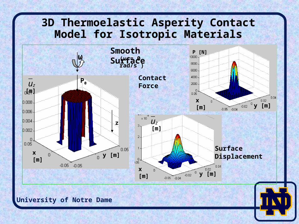
3D Thermoelastic Asperity Contact Model for Isotropic Materials
z
ω
P0
Smooth Surface
Contact Force
Surface Displacement
(ω = 0 rad/s )
y [m]x [m]
[m]
P [N]
[m]
zu
zu
x [m]
y [m]x [m]
y [m]

University of Notre Dame
3D Thermoelastic Contact Model Verification
Pij (contact force)Pij (contact force)
uz (numerical result)uz (theory result)3D Hertz problem
P0 = 2×10⁵ N
E = 72×109 Pa
= 0.2
Rsphere = 0.25 m
uz(0,0) = 2.44×10⁻⁴ m
uz(0,0) = 2.52×10⁻⁴ m (theory)
P(0,0) = 9.26×10³ N
P(0,0) = 9.47×10³ N (theory)
P0
z
X1 [m]
Z [m]
X2 [m]
X1 [m]
Normal Displacement [m]
X2 [m]
X1 [m] X2 [m]
Normal Displacement [m]
Normal Contact Force [N]
X2 [m] X1 [m]
Normal Contact Force [N]
X1 [m] X2 [m]

University of Notre Dame
3D Thermoelastic Asperity Contact Model for Isotropic Materials
3D Hertz problem
P0 = 2×10⁵ NE = 72×109 Pan = 0.2Rsphere = 0.25 m
Subsurface von-Mises stress (x-z plane)[Pa]
[m]1[m]
P0
z
X1 [m]
Z [m]
X2 [m]

University of Notre Dame
3D Thermoelastic Asperity Contact Model for Isotropic Materials
Thermoelastic Hertzian result (smooth surface)
X1 [m]
X1 [m] X1 [m]
X1 [m] X2 [m] X2 [m]
X2 [m] X2 [m]
Normal Displacement [m] (ω =10 rad/s)
Normal Displacement [m] (ω =100 rad/s)
Normal Displacement [m] (ω =200 rad/s)
Normal Displacement [m] (ω =1000 rad/s)

University of Notre Dame
3D Thermoelastic Asperity Contact Model for Isotropic Materials
Thermoelastic Hertzian result (rough surface)
X1 [m] X1 [m]
X2 [m] X2 [m] X2 [m]
Original profile [10-3 m]
X1 [m]
Normal Displacement [10-4 m] (ω =200 rad/s)
Normal Displacement [10-4 m] (ω=10 rad/s)

University of Notre Dame
3D Thermoelastic Asperity Contact Model for Isotropic Material (Ring Surface)
(Original profile) (smooth) (rough)
(Surface Displacement )
(Contact Force )
(ω = 10)
y [m]x [m]
h[m] uz[m]uz[m]
Pij[N] Pij[N]h[m]
x [m] x [m] x [m]
x [m]x [m] y [m] y [m]
y [m]y [m]

University of Notre Dame
Three-Dimensional Thermoelastic Rough Surface Contact Model for Anisotropic Materials

University of Notre Dame
Asperity Contact Model for Anisotropic Material
Basic Equations of Anisotropic Elasticity ksijksij C
Type of Anisotropic Material (Based on Symmetry Planes)Triclinic Materials (21)
Monoclinic Materials (13)
Orthotropic Materials (9)
Trigonal Materials (6)
Tetragonal Materials (6)
Transversely Isotropic (or Hexagonal) Materials (5)
Cubic materials (3)
Isotropic Materials (2)

University of Notre Dame
3D Contact Model for Anisotropic Material
3D Green’s function for infinite anisotropic medium:
Idea: obtain the result in term of a line integral on an oblique plane in the three-dimensional space
General deformation:
Note: f will be calculated due to different conditions
11
1 2 000
1 1 [ ] [ ]( , ,0) [ ]2 sin( )
x x dr
S Lu L f
0
0
0
1 ( )
1 ( )
1 ( )
d
d
d
1
2
3
S[k] N
H[k] N
L[k] N
1
1
1
( ) ( ) ( )
( ) ( )
( ) ( ) ( ) ( ) ( )
T
T
1
2
3
N T R
N T
N R T R Q
1 1 1 2 2 2, , .ik i k j s ik i k j s ik i k j sQ C n n R C n m T C m m
University of Notre Dame
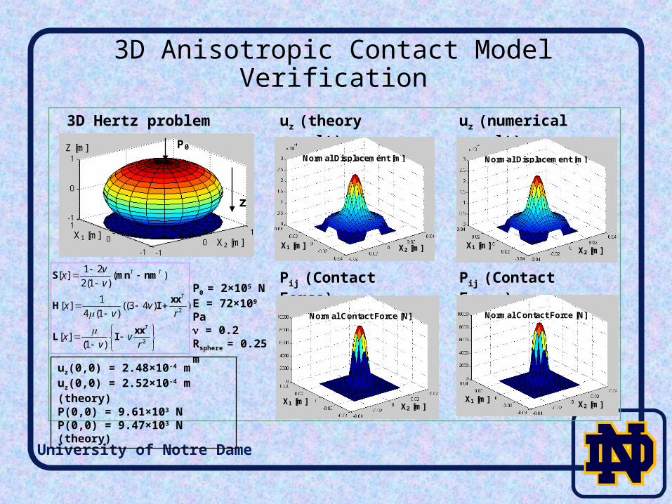
3D Anisotropic Contact Model Verification
Pij (Contact Force)Pij (Contact Force)
uz (numerical result)uz (theory result)3D Hertz problem
P0 = 2×10⁵ NE = 72×109 Pa = 0.2Rsphere = 0.25 m
x y
uz(0,0) = 2.48×10⁻⁴ muz(0,0) = 2.52×10⁻⁴ m (theory)P(0,0) = 9.61×10³ NP(0,0) = 9.47×10³ N (theory)
P0
z
X1 [m]
Z [m]
X2 [m]
X1 [m]
Normal Displacement [m]
X2 [m]
X1 [m] X2 [m]
Normal Displacement [m]
Normal Contact Force [N]
X2 [m] X1 [m]
Normal Contact Force [N]
X1 [m] X2 [m]
2
2
1 2[ ] ( )2(1 )
1[ ] ((3 4 ) )4 (1 )
[ ](1 )
T T
T
T
vxv
x vv r
x vv r
S mn nm
xxH I
xxL I

University of Notre Dame
3D Contact Model for Anisotropic Material
Anisotropic Application E1=144x109 pa, E2=E3=72x109 pa, v=0.2, G=E2/[2*(1+v)]
Normal pressure distribution [pa] Contour for the normal pressure distribution

University of Notre Dame
Future Work
Investigate on the case that have different fiber property on the different region.
Improve the algorithm to reduce the calculation time.

University of Notre Dame
Thank you