university of oulu department of process and environmental ... · department of process and...
TRANSCRIPT

1
University of Oulu
Department of Process and Environmental
Engineering
Systems Engineering Laboratory
477021A Laboratory Exercises of Process Engineering
Programmable Logic Controller in a dosing process
2013
version 3

2
1. Basics of PLC
Industrial control systems are usually used in large applications such as paper machines, chemical processes
or power plants. They are specifically purpose-built and consist of microprocessor-based apparatus and
software. A distributed control system (DCS) refers to a control system in which the controllers are spread
throughout the system and connect by networks.
Smaller automation applications can be implemented with programmable logic controllers (PLC). They are
also based on microprocessors and software. They are considerably cheaper than the lower level
automation systems they replace. PLC systems are widely used in bulk manufacture or if the production is
low-volume, flexible and needs fast changes.
PLCs first emerged in USA in the late 1960s to meet the needs of automotive industry. Before PLCs the
production was controlled by relay systems with hard-wire control panels that needed time-consuming re-
wiring every time a change was needed. PLCs faced great success because of the benefits of fast and
flexible reprogramming by software revision. The evolution of microprocessors in the 70s and 80s enabled
PLCs to become more versatile and has increased their functionality. Today the largest PLC and control
systems have very much in common.
There is a wide supply of different PLCs on the market, but their functions are very much the same. All PLCs
independent of the manufacturer (Siemens, Omron, Allen-Bradley, Mitsubishi, ABB…) can be programmed
with logic system design. The similarity of different PLCs enables the users to switch from one PLC to
another easily.
There are a lot of books, manuals and tutorials available on PLCs and logic programming.
The PLC in the laboratory belongs to Siemens SIMATIC 1200 series. It is very useful to take a look at the
Siemens SIMATIC Manual, available for everyone on Siemens website (http://www.siemens.com). Search
for “simatic manual” or something similar to find the file “Simatic S7-1200 Programmable controller,
System manual”, for example. It covers the basics of creating a program with Siemens PLC.

3
1.1 STRUCTURE
Typically a PLC consists of different modules that are not necessarily physically next to each other. All PLCs
have the elements shown in picture 1.
Figure 1. PLC elements
Input modules
All input signals from switches, limit switches, buttons and so on are connected to the input module. The
signals can be binary (ON/OFF) or analog (temperature, pressure…).
Output modules
Output module is connected to valves, indicator lights, contactors and so on. Like inputs the outputs can be
binary or analog.
CPU (Central Processing Unit) and program memory
CPU consists of a microprocessor and an operating system. Program memory contains the user-made
application program that instructs the PLC to perform in a desired manner.
CPU reads the input modules, executes the application program in program memory and then updates the
output module.
CPU can be sweeping or real-time. In a sweeping CPU, there are three action phases: reading the inputs,
saving them in the auxiliary memory space, running the program and writing the outputs. Cycle time can be
Power
supply
CPU (Central
Processing
Unit)
Input
modules
Output
modules
Programming
device
Program
memory
4
fixed or changing. During one sweeping cycle, no changes can be applied. Therefore a sweeping CPU is
often too slow.
In a real-time PLC there are no auxiliary memories. I/O can change during a program cycle. The problem is
that real-time functionality can cause hazards in action scheduling.
1.2 PROGRAMMING LANGUAGES
Programming of the PLC is done with a separate programming device, in this case a PC. The program is then
transferred to the PLC program memory that executes the program.
Programming of the PLC can be done in different languages such as statement list or logic function block
diagram. Basic logic operations such as (AND, OR, NOR, NAND…), timers, counters, RS flip-flops and special
operations (PID-control, for example) can be used in all languages.
It is recommended that the basics of logic programming are studied und understood before attending this
lab work.
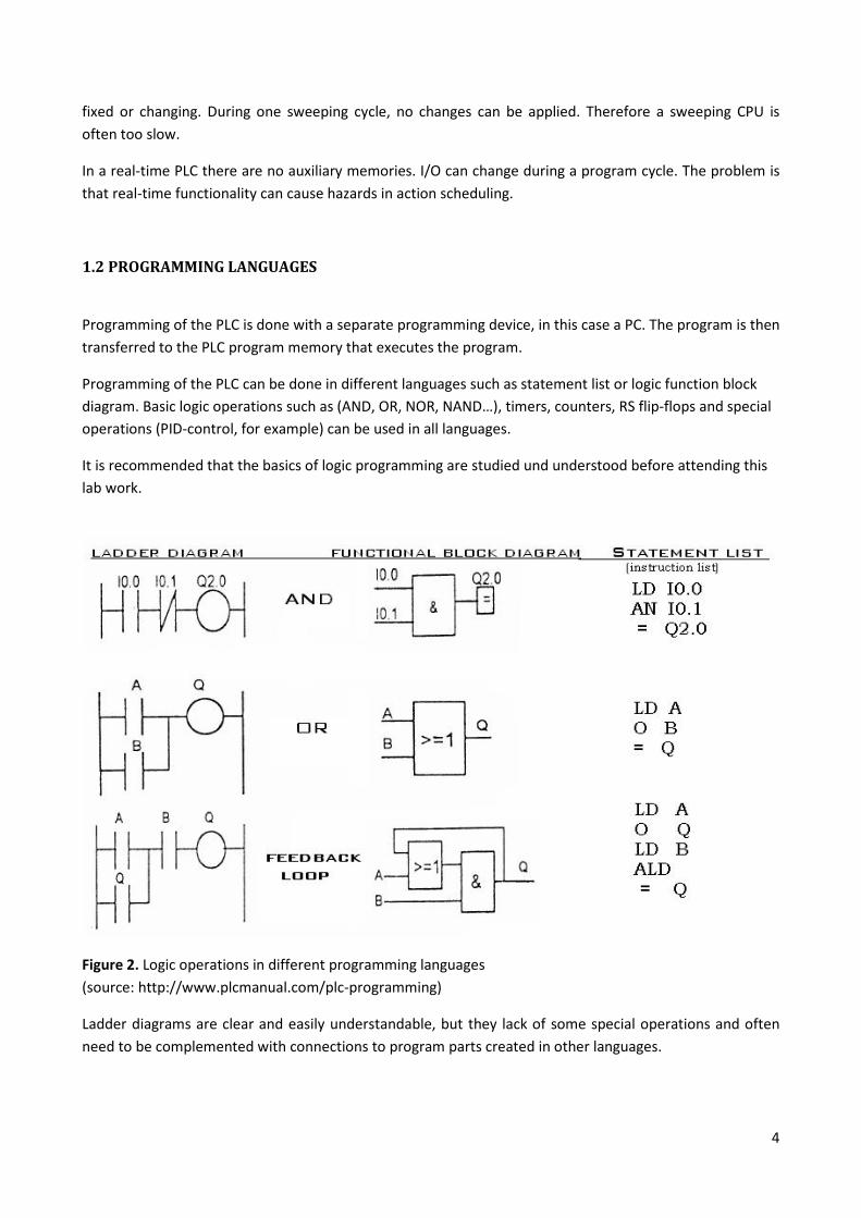
Figure 2. Logic operations in different programming languages
(source: http://www.plcmanual.com/plc-programming)
Ladder diagrams are clear and easily understandable, but they lack of some special operations and often
need to be complemented with connections to program parts created in other languages.

5
Function block diagrams are logic diagrams. The functions of different blocks are illustrated in rectangular
boxes.
Statement list is the most complicated programming language. It can be used in otherwise difficult cases
but its use requires more experience and knowledge than the two languages presented before.
2. Lab work
2.1 SET-UP
The process to be controlled is a simple dosing system.
The set-up consists of a water tank (20 l), a tray conveyor, a basin and instrumentation devices. The set-up
also has a water temperature controlling system that is not used in this dosing experiment.
There are two limit switches and four solenoid valves in the water tank. There is one limit switch and one
relay for the conveyor.
(LS1 is out of use because of malfunction, but it would be a limit switch at the bottom of the tank.)
LS2 is a limit switch located on the lowest operating level in the tank (around 50%).
LS3 is the high tank level limit switch (around 85%).
FS1 is the solenoid valve that controls the air-driven stirring device.
FS2 is the filling valve.
FS3 is the emptying valve.
FS4 is the dosing valve.
GS1 is a limit switch that indicates if a tray is below the dosing valve.
SS1 is the relay that controls the conveyor belt motor.
Each of these switches and valves has only two states: 1 or 0.
When a valve is in state 1, it is fully opened; in state 0 it is fully closed.
When a limit switch is in state 1, it is covered with water or has detected an object.
When a motor is in state 1, it is running.

6
2.2 CREATING A PROJECT
Siemens STEP7 – software can be used to create projects with S7-programs and hardware configuration.
If the program has a lot of I/O (inputs/outputs), it is recommended to define the used hardware first. While
configuring the hardware, the user is allowed to change the parameters and properties of I/O-modules, for
example define which memory areas are used.
All programs need an organization block, OB1. The system calls the OB after a malfunction, power loss or
start-up. Simple programs with linear structure (step by step) can be programmed straight to the OB1, but
usually the OB1 only reads the inputs and calls the lower level programs (FC, FB, OB…) depending on
conditions.
Function blocks (FB) differ from functions (FC) in memory usage. Function blocks need their own data block
(DB) to store the data and variables it needs. Functions (FC) do not need data blocks.
SIMATIC MANAGER
STEP7 can be accessed through TIA Portal Step 7. When the Manager opens, it will propose TIA Portal to
the user create new projects.
TIA Portal Simatic Step7 steps:
1. Open TIA Portal V11. Presentation of the structure of the S7-project.
Click “Create” to continue.
2. Choose the right CPU.
In this lab set-up we use CPU 1212C and Order no. 6E7 212-1BE31-0XB0 and Firmware: V3.0 Click
“Add”.
3. The cyclic main program is always built in OB 1.
Programming language is also chosen at this point. Preferably use FBD (function block diagram) or
LAD (ladder diagram). STL stands for statement list.
4. Project view is opened (Fig. 3).
The cyclic main program is always built in OB 1 is created.
Programming language is also chosen at this point. Preferably use FBD (function block diagram) or LAD
(ladder diagram). STL stands for statement list.

7
Figure 3. TIA Portal Step 7 Project view.
After finishing the wizard, the Step 7 window opens and displays the created project. The project structure
is displayed in the left frame; the right frame is used to control the contents of the folders.
The folders consist of
- “PLC_1”: all information and components related to hardware.
- “CPU 1212C”: all information on connections between the CPUs, programming and operating
devices.
- “Program blocks” the user can create blocks (OB, FB, FC and so on).
- “PLC tags”: all parts related to programming.
In “tags” the user can give symbolic names to absolute memory addresses.

8
SYSTEM CONFIGURATION
System configuration starts with defining the hardware. The racks are numbered and the modules are
given their places. The system will give modules their memory areas and set inputs and outputs to their
default values. Change the digital inputs and outputs from default values to 32.
Figure 4. Opened Device overview in PLC_1.
In Properties and “Ethernet Addresses” can change the Profinet Ethernet IP-address. IP address is
____.____.____.____ Subnet mask: 255.255.240.0, Use IP router with address: : ____.____.____.____ (Fig.
4).
Modules are automatically given their memory areas (I for inputs, Q for outputs). These memory areas can
be altered by double-clicking the module and giving the new start areas (the end area depends on the
memory usage of the module).

9
In the lab work, change the I/O module memory areas to I32 and Q32. The addresses of inputs and outputs
will be I 32.0, I 32.1, Q 32.0, Q 32.1 and so on, the latter bit describing in which gate of the module the
input/output is connected.
Symbolic names can be used in programming instead of absolute addresses by defining a symbol list that
tells which symbol is related to which address and what type the input represents (for example BOOL is
Boolean, true/false). The same symbols can then be used in all parts of the project. It can find from the PLC
tags
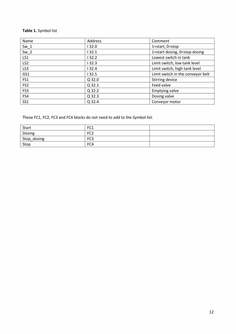
Table 1 shows the suggested symbolic names for the lab work. FC1, FC2, FC3 and FC4 blocks can be create
from Program blocks|Add new block.
DOWNLOADING TO MODULE
When the hardware configuration or a program is ready, it must be loaded to the CPU. Loading will be
started by clicking “download to module” in the fast menu. First time download the modules from PC to
PLC. Select PLC_1 folder. Click download to module (Fig. 5).
Figure 5. Download the project from PC to PLC.
Select connection PG/PC with connection PN/IE and Broadcom Netlink. Select IP address and download the
project with LOAD-button (Fig. 6).

10
Figure 6. Ethernet connection between PC and PLC.

11
3. Program for the dosing system
The program is built by using OB1 and four functions FC1-4 that are responsible for different actions.
OB1 acts as the main program that calls up the functions depending on conditions (input states).
Table 2 explains how the program should work.
The program is created in parts and tested every once in a while to ensure and demonstrate program
action.
12
Table 1. Symbol list
Name Address Comment
Sw_1 I 32.0 1=start, 0=stop
Sw_2 I 32.1 1=start dosing, 0=stop dosing
LS1 I 32.2 Lowest switch in tank
LS2 I 32.3 Limit switch, low tank level
LS3 I 32.4 Limit switch, high tank level
GS1 I 32.5 Limit switch in the conveyor belt
FS1 Q 32.0 Stirring device
FS2 Q 32.1 Feed valve
FS3 Q 32.2 Emptying valve
FS4 Q 32.3 Dosing valve
SS1 Q 32.4 Conveyor motor
These FC1, FC2, FC3 and FC4 blocks do not need to add to the Symbol list.
Start FC1
Dosing FC2
Stop_dosing FC3
Stop FC4

13
Table 2. The dosing program
4