university of stuttgart diploma thesis · university of stuttgart diploma thesis examiner: prof....
TRANSCRIPT
University of StuttgartDiploma Thesis
Examiner: Prof. Dr. Hans-Joachim WunderlichSupervisor: Dr. Rainer Dorsch (hardware), Dr. Thomas Schöbel-Theuer (linux)
Begin: 01.05.2002End: 31.10.2002/14.11.2002(extension)
CR-Classification: B.7.1 C.1 C.5 D.4
Dipoma Thesis Nr. 2013
Design of aMemory Management Unit for
System-on-a-Chip Platform"LEON"Konrad Eisele
Division of Computer ArchitectureInstitute of Computer Science
Breitwiesenstr. 20-2270565 Stuttgart

2

3
A Memory Management Unit (MMU) for SoC Platform LEON was designed and integratedinto LEON. The MMU comply to the SPARC Architectural Manual V8 reference MMU (SR-MMU).

4
Contents
0.1 Abbreviation index . . . . . . . . . . . . . . . . . . . . . . . . . . . . . . . . 7
1 Introduction 9
2 Memory Management 112.1 Virtual Address Spaces . . . . . . . . . . . . . . . . . . . . . . . . . . . . . . 112.2 Paging and Segmentation . . . . . . . . . . . . . . . . . . . . . . . . . . . . . 122.3 Hardware support . . . . . . . . . . . . . . . . . . . . . . . . . . . . . . . . . 14
3 System-on-a-Chip platform LEON 153.1 LEON pipeline . . . . . . . . . . . . . . . . . . . . . . . . . . . . . . . . . . 163.2 Cache subsystem . . . . . . . . . . . . . . . . . . . . . . . . . . . . . . . . . 17
3.2.1 Data cache (DCache) . . . . . . . . . . . . . . . . . . . . . . . . . . . 183.2.2 Instruction cache . . . . . . . . . . . . . . . . . . . . . . . . . . . . . 183.2.3 AMBA ASB interface . . . . . . . . . . . . . . . . . . . . . . . . . . 20
4 SPARC standard 234.1 RISC . . . . . . . . . . . . . . . . . . . . . . . . . . . . . . . . . . . . . . . 234.2 SPARC V8 . . . . . . . . . . . . . . . . . . . . . . . . . . . . . . . . . . . . 23
4.2.1 Register windows . . . . . . . . . . . . . . . . . . . . . . . . . . . . . 234.2.2 SPARC instruction overview . . . . . . . . . . . . . . . . . . . . . . 24
5 SPARC V8 Reference MMU (SRMMU) 275.1 SPARC SRMMU translation overview . . . . . . . . . . . . . . . . . . . . . . 275.2 ASI: Alternate Space Instructions . . . . . . . . . . . . . . . . . . . . . . . . 28
5.2.1 ASI:MMU register access . . . . . . . . . . . . . . . . . . . . . . . . 295.2.2 ASI:flush/probe . . . . . . . . . . . . . . . . . . . . . . . . . . . . . . 31
5.2.2.1 flush . . . . . . . . . . . . . . . . . . . . . . . . . . . . . . 325.2.2.2 probe . . . . . . . . . . . . . . . . . . . . . . . . . . . . . . 32
5.2.3 ASI: MMU diagnostic access I/D TLB . . . . . . . . . . . . . . . . . 325.2.4 ASI: MMU physical address pass through . . . . . . . . . . . . . . . . 325.2.5 ASI: I/DCache flush . . . . . . . . . . . . . . . . . . . . . . . . . . . 32
6 Design options 356.1 Physically tagged / physically indexed (PTPI) . . . . . . . . . . . . . . . . . . 356.2 Physically tagged / virtually indexed (PTVI) . . . . . . . . . . . . . . . . . . . 35
5

6 CONTENTS
6.3 Virtually tagged / virtually indexed (VTVI) (SRMMU) . . . . . . . . . . . . . 376.3.1 Writebuffer . . . . . . . . . . . . . . . . . . . . . . . . . . . . . . . . 37
6.3.1.1 Virtual writebuffer . . . . . . . . . . . . . . . . . . . . . . . 376.3.1.2 Physical writebuffer . . . . . . . . . . . . . . . . . . . . . . 38
6.4 Design chosen . . . . . . . . . . . . . . . . . . . . . . . . . . . . . . . . . . . 386.4.1 VTVI DCache, physical writebuffer (DCache.vhd) . . . . . . . . . . . 406.4.2 VTVI ICache (ICache.vhd) . . . . . . . . . . . . . . . . . . . . . . . . 406.4.3 Other changes made to LEON . . . . . . . . . . . . . . . . . . . . . . 40
7 MMU design components 437.1 Functional overview . . . . . . . . . . . . . . . . . . . . . . . . . . . . . . . . 457.2 Component Overview . . . . . . . . . . . . . . . . . . . . . . . . . . . . . . . 50
7.2.1 Memory Management Unit (MMU) . . . . . . . . . . . . . . . . . . . 507.2.2 Translation Lookaside Buffer (TLB) . . . . . . . . . . . . . . . . . . . 507.2.3 Translation Lookaside Buffer Entry (TLBCAM) . . . . . . . . . . . . 507.2.4 Table Walk (TW) . . . . . . . . . . . . . . . . . . . . . . . . . . . . . 517.2.5 Least Recently Used (LRU & LRU entry) . . . . . . . . . . . . . . . . 51
7.3 Possible future optimizations . . . . . . . . . . . . . . . . . . . . . . . . . . . 517.3.1 1 cycle penalty implementation . . . . . . . . . . . . . . . . . . . . . 517.3.2 0 cycle penalty implementation . . . . . . . . . . . . . . . . . . . . . 517.3.3 Flush optimization . . . . . . . . . . . . . . . . . . . . . . . . . . . . 53
8 Design Flow 558.1 XESS XSV800 board development . . . . . . . . . . . . . . . . . . . . . . . . 55
8.1.1 Design flow . . . . . . . . . . . . . . . . . . . . . . . . . . . . . . . . 558.1.1.1 XESS board . . . . . . . . . . . . . . . . . . . . . . . . . . 568.1.1.2 Modelsim . . . . . . . . . . . . . . . . . . . . . . . . . . . 568.1.1.3 Synthesis . . . . . . . . . . . . . . . . . . . . . . . . . . . . 578.1.1.4 Software . . . . . . . . . . . . . . . . . . . . . . . . . . . . 57
9 Linux kernel 619.1 Linux file organization and make system . . . . . . . . . . . . . . . . . . . . . 62
9.1.1 LEON dependent parts . . . . . . . . . . . . . . . . . . . . . . . . . . 639.1.1.1 “make xconfig” . . . . . . . . . . . . . . . . . . . . . . . . 639.1.1.2 “make vmlinux” . . . . . . . . . . . . . . . . . . . . . . . . 63
9.2 Linux bootup . . . . . . . . . . . . . . . . . . . . . . . . . . . . . . . . . . . 649.3 Memory . . . . . . . . . . . . . . . . . . . . . . . . . . . . . . . . . . . . . . 65
9.3.1 Memory Management . . . . . . . . . . . . . . . . . . . . . . . . . . 669.4 Processes . . . . . . . . . . . . . . . . . . . . . . . . . . . . . . . . . . . . . 67
9.4.1 Process stack . . . . . . . . . . . . . . . . . . . . . . . . . . . . . . . 679.4.2 Scheduling . . . . . . . . . . . . . . . . . . . . . . . . . . . . . . . . 68
10 Appendix A: Components 73
0.1. ABBREVIATION INDEX 7
11 Appendix B: MMU distribution 7911.1 Distribution overview . . . . . . . . . . . . . . . . . . . . . . . . . . . . . . . 7911.2 Subdirectory mmu/modelsim/ . . . . . . . . . . . . . . . . . . . . . . . . . . 7911.3 Subdirectory mmu/syn/ . . . . . . . . . . . . . . . . . . . . . . . . . . . . . . 8011.4 Subdirectory mmu/tbench/ . . . . . . . . . . . . . . . . . . . . . . . . . . . . 80
11.4.1 Testbenches for MMU components mmu/tbench/comp . . . . . . . . . 8011.4.1.1 TLB_cam.vhd . . . . . . . . . . . . . . . . . . . . . . . . . 8011.4.1.2 tw_tb.vhd . . . . . . . . . . . . . . . . . . . . . . . . . . . 8011.4.1.3 TLB_tb.vhd . . . . . . . . . . . . . . . . . . . . . . . . . . 8011.4.1.4 mmu_tb.vhd . . . . . . . . . . . . . . . . . . . . . . . . . . 80
11.5 Subdirectory mmu/scripts/ (XESS board development) . . . . . . . . . . . . . 8111.5.1 syn.pl: Xilinx tool chain build scripts . . . . . . . . . . . . . . . . . . 8111.5.2 selexo.sh : Handling the board . . . . . . . . . . . . . . . . . . . . . . 82
11.6 Subdirectory mmu/tsource . . . . . . . . . . . . . . . . . . . . . . . . . . . . 8211.6.1 image: Creating page table hierarchies . . . . . . . . . . . . . . . . . . 83
11.6.1.0.1 Analysing page table hierarchies . . . . . . . . . . 8411.6.1.0.2 Dumping memory content of testbench . . . . . . . 85
11.6.2 Small Operating System (SOS) . . . . . . . . . . . . . . . . . . . . . 8511.7 Subdirectory mmu/vhdl/ . . . . . . . . . . . . . . . . . . . . . . . . . . . . . 8611.8 Subdirectory mmu/xess/ (XESS board development) . . . . . . . . . . . . . . 86
12 Appendix C: MMU source 8712.1 Source code . . . . . . . . . . . . . . . . . . . . . . . . . . . . . . . . . . . . 87
Bibliography 89
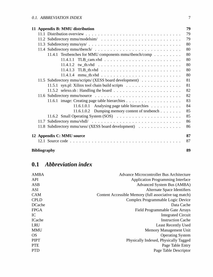
0.1 Abbreviation index
AMBA Advance Microcontroller Bus ArchitectureAPI Application Programming InterfaceASB Advanced System Bus (AMBA)ASI Alternate Space IdentifiersCAM Content Accessible Memory (full associative tag match)CPLD Complex Programmable Logic DeviceDCache Data CacheFPGA Field Programmable Gate ArraysIC Integrated CircuitICache Instruction CacheLRU Least Recently UsedMMU Memory Management UnitOS Operating SystemPIPT Physically Indexed, Physically TaggedPTE Page Table EntryPTD Page Table Descriptor

8 CONTENTS
RTOS Real Time Operating SystemSoC System on a ChipSPARC V8 SPARC architectural manual Volume 8SRMMU SPARC Reference MMUTLB Table Lookaside Buffer (PTE cache)VHDL Very High Speed Integrated Circuit Hardware Description LanguageVIPT Virtually Indexed, Physically TaggedVIVT Virtually Indexed, Virtually Tagged

Chapter 1
Introduction
This diploma thesis is inspired by the idea to get a full feature Linux API running on the opensource System-on-a Chip (SoC) platform LEON, which is a synthesisable VHDL implementa-tion of the SPARC Architectural Manual V8 standard. Linux has recently gained wide accep-tance. With a rich literature footage and a broad spectrum of online documentation it is fairlywell understood. Porting Linux onto LEON was especially inviting because Linux has alreadybeen ported to the SPARC architecture, running on Sun workstations 1. However only SPARCprocessors with a Memory Management Unit (MMU) are supported. The current LEON distri-bution does not include a MMU because LEON is targeted on embedded realtime applications,where nondeterministic page faults of the MMU could cause trouble to the realtime require-ments of these applications. Also in a deeply embedded environment, where normally only onefixed task has to run, the overhead of Virtual Memory Management is quite significant. TheSPARC Architectural Manual V8 (SPARC V8) does not require a MMU to be present, howeverthe SPARC V8 (which the LEON integer unit implements) already defines a SPARC ReferenceMMU (SRMMU). This suggested that when adding the SRMMU to LEON, porting Linux wouldbe a straightforward job. Therefore, the main goal of this diploma thesis is the implementationof a SRMMU and it’s integration into the LEON SoC platform. This report will concentrateon the hardware side: the design and implementation of a SRMMU. Running Linux on LEONmay not be practical for embedded realtime applications, nevertheless there could be quite a fewfields of application (PDA’s or the like). Another nice aspect is that Linux running on LEONSoC would be Open Source from gate level on2.
The MMU supports memory management in hardware. Chapter 2 gives an introduction tothe theoretical concepts of memory management. After that, chapter 3 gives a brief overviewover the SoC platform LEON, which had to be extended with a MMU. The LEON integer unitimplements the SPARC architecture according to the SPARC Architectural Manual V8, which isdescribed in Chapter 4. The SPARC Architectural Manual V8 does define a reference MMU inAppendix H, the SRMMU, which is described in Chapter 5. The following chapters will focuson the implementation of the MMU in hardware. Also the SRMMU suggests a specific designin detail, there are nevertheless a variety of design options from which to choose. These optionsare discussed in Chapter 6. Chapter 7 describes the actual implemented design, which is the
1This source turned out to be well documented and, because of the RISC nature of the low level assembler parts,relatively easy to understand
2Of course excluding the tools for synthesis which are not open source (yet).
9
10 CHAPTER 1. INTRODUCTION
main part of this report: First a functional overview is given for the MMU as a whole, then foreach operation the MMU supports. Each design component of the MMU is described separately.Some notes on future timing optimization follow. Chapter 8 will focus on the design flow, givingan overview on the tools involved. Chapter 9 start with the Linux porting effort. It will describesome fundamentals about the working of the Linux kernel and deal with aspects related to tomemory management in Linux, however for detailed descriptions refer to for instance to [5].Because of the wide range of this diploma thesis, spanning from hardware design to kernelhacking, naturally some parts will not be covered in full detail. Emphasis in this diploma thesiswas put on the practical side. The source distribution can be downloaded from [7].
Development was done on a XSV300 and 800 board with a Xilinx Virtex FPGA chip forhardware prototyping.

Chapter 2
Memory Management
Historically Memory Management evolved out of the need implied by a multiuser/multitaskingenvironment [14]. In such an environment, where multiple users share one memory resource,mechanisms has to be introduced to prohibit accidental access, that would crash the whole sys-tem, or unauthorized access, to protect private data. One of the first OS that pioneered the fun-damental concepts of a multiuser/multitasking system was MULTICS , dating back to the late’60. It implemented the concept of virtual addresses in hardware by 2 major techniques: pagingand segmentation [16]. These principles hold to date, most current architecture use paging orsegmentation or a combination of both.
A Virtual Memory Management scheme is defined by two main functions: translation andprotection. Translation dissolve the mapping of virtual addresses into physical addresses, whichin term is closely linked to memory allocation - where paging is somehow related to fixed sizeallocation whereas segmentation is related to variable size allocation, each of which has itsadvantages and disadvantages. The second function is protection. Each entity in paging andsegmentation hold access parameters which in turn reflect on the underlying physical resource.The SPARC Memory Management architecture, which is the target of this diploma thesis, onlysupports paging, therefore segmentation will only be covered briefly.
2.1 Virtual Address Spaces
Virtual addresses draws a clear border of abstraction. In a Virtual Memory Management schemethe actual physical memory configuration is transparent to the running program. A distinct fea-ture of this is that programs can be programmed for an address space at compile time that isactually larger than the physical address space at runtime. The uniformity frees the programmerof memory considerations. The seamless integration of other resources than memory, such asfiles, reduce system and hardware dependencies [14]. Two of the main techniques for imple-menting virtual address spaces in hardware are paging and segmentation, which are discussedin the following sections.
11

12 CHAPTER 2. MEMORY MANAGEMENT
2.2 Paging and Segmentation
Paging use fixed size pages as base unit, usually 4k large. It provides one virtual address spacein the logical domain, which is mapped to physical memory through one mapping entry foreach page in the virtual address space, which is shown in figure 2.1. Each mapping entry holdsadditional information for OS use. This is shown in figure 2.1.
1 2 3 4 5 n
1 2 3 4
Logical level
Physical Level
Linear address space
Mapping
Figure 2.1: Paging
Segmentation on the other hand side uses variable size segments. Each segment form oneindependent virtual address space, however only one mapping per segment is provided, thereforea segment has to be contiguous in physical memory. Each segment holds additional information,which include its length and flags for OS use. This is shown in figure 2.2.
addressLinear
space
addressLinear
space
Mapping
2
Linear address space
31
Linear address space
Linear Address Space Linear Address Space
Physical level
Logical level
Figure 2.2: Segmentation
The paging example figure 2.1 shows a mapping (1,1) (2,3) (4,2). Adjacent pages in thevirtual address space can be scattered in physical memory. This makes memory allocation inpaging immune to fragmentation. Paging forms the base for swapping (demand paging) of theOS, where not the whole virtual address space has to be constantly present in physical memory.Pages can be swapped in/out from hard disc on demand. The corresponding flags in the pagetable entries keep track on this process.
Both paging and segmentation map from virtual addresses to physical addresses. For thetranslation several data structures are possible to store the mapping: It can for example be doneby using one big flat table. In this case the virtual address form an offset into the table where thecorresponding descriptor for the physical address is found. For the above paging example thiswould look somehow like this:

2.2. PAGING AND SEGMENTATION 13
virtual index physical1 12 33 -4 25 ...... ...
In case of segmentation a segment it is called a segment descriptor table. In case of pagingit is called a page table. In case of paging with one flat page table a 2**32 virtual addressspace with 4k size pages would require 2**20 entries, which would occupy around 4 MB 1[23].Therefore in most cases a sparse page table hierarchy is used. An example of this can later beseen in section 5. In a page table hierarchy the virtual address is subdivided into several indices,that does each offset into the next level of the page table tree. By interrupting the traversal inbetween, it is also possible to define larger pages (than the fixed size 4k pages). For instance inthe SPARC page table tree with 4 levels, level 0 maps 4G bytes (whole virtual address space),level 1 maps 16M, level 2 maps 256K of memory and level 3 maps the standard 4K pages.Figure 2.3 shows a schematic of the page table traversal.
lastlevel of
hirarchy?
authorizedAccess
mode?
Main memory
(table lookup)TLB
Hit
Yes
No
Yes
No
Miss
Item
in memory?present
Protection violationexception
Mapping descriptor
Storein TLB
Virtual address
Physical address Fetch from disc
Page fault exception
Figure 2.3: Page table hierarchy traversal. (Related to [14])
Along the physical memory address the page table entries store additional flags, which en-able the operating system to swap unused pages out of physical memory onto disk and im-plement protection on pages. In paging only one hardware implemented logical entity exist.Therefore protection in paging must be done by subdividing the entire virtual address space intoattributed regions, merely setting another layer on top. This subdivision can only be done in the
1On 64-bit computers this would even increase to 2**52 entries which is not tolerable at all, therefore anotherdata structure instead of a lookup table has to be used, for instance a inverted page table, which is a hash [23].

14 CHAPTER 2. MEMORY MANAGEMENT
granularity defined by the page size (usually 4k) and is limited by the fact that these regions arebound to one virtual address space (overlapping may occur)[23]. The sub partitioning into dif-ferent protected regions is partly done at compile time2. On the other hand side in segmentationeach segment form a logical entity with its own rights3.
2.3 Hardware support
Hardware support include
� Table Lookaside Buffer (page table entries cache)
� Updating page table entries flags
� Exception signals
� Table walk
The most primitive form of translation would be to raise an exception on every memory accessand let the OS do the translation from virtual to physical addresses in software. Hardware sup-port accelerates this process by adding the Table Lookaside Buffer (TLB), which is in principlea cache of previous successful translations. In most cases it is build as a full-associative cache.With an appropriate processor design that tightly integrates the TLB into the overall structurethe translation can be done without any delay on a TLB hit. In the course of this diploma thesisit became clear that it is hard to add a TLB with zero wait states to a design previously notdesigned with a MMU in mind.
On a TLB miss the page tables has to be traversed (Table walk). This can be done in hardwareor in software. The advantage of a software TLB miss handle could be that an advanced TLBupdating scheme could be implemented to minimize TLB misses. Nevertheless TLBs generallyhave a high hit ratio.
Additional hardware support is provided by updating the referenced and modified flags of apage table entry and checking access permissions. The referenced flag logs any accesses to thepage, the modified flag logs write accesses to a page. These flags in turn will be used by the OSon swapping operations. On a privilege or protection violation the hardware raises a signal thatcause the processor to trap.
2Or dynamically using the mmap() call in Linux.3Another interesting feature of segmentation is the possibility of dynamic linking at runtime, a feature proposed
by the late MINICS architecture. In a segmented Memory Management scheme a function would be a segmentwith the appropriate access rights. A jump to function n would equal in jumping to the offset 0 of segment n. Ifany program uses a distinct n at compile time relinking a new function for all running programs in the runningsystem would be possible by exchanging the segment descriptor in the segment descriptor table at position n. Nore-compilation of programs or rebooting of the whole system would necessary [23].

Chapter 3
System-on-a-Chip platform LEON
This chapter gives an overview of the LEON architecture. When adding a MMU to LEON, ithad to be placed somewhere between the integer unit, the instruction cache (ICache), the datacache (DCache), and the AMBA memory interface. After giving a brief overview over theglobal LEON system architecture the interaction of the LEON pipeline with the DCache andICache will be presented in more detail. Figure 3.1 shows a simplified overview of the LEONarchitecture.
Memory controller(mctrl.vhd)
Timer(timers.vhd)
(ioport.vhd)I/O Ports
IRQ(irqctrl.vhd)
UARTs (uart.vhd)
AMBA Arbiter(ahbarb.vhd)
AHB/APB Bridge(bpbmst.vhd)
Instruction Cache(icache.vhd)
Data Cache(dcache.vhd)
MMU(mmu.vhd)
Integer Unit(iu.vhd)
Amba Interface(acache.vhd)
Debug SerialLink
(dcom.vhd)
Debug Support Unit (dsu.vhd)
(mcore.vhd)
PROM I/O SRAM SDRAM
Advanced High Performancs Bus (AHB)
Advanced Peripheral Bus (AHB)
PI/O Ports, UARTUART
Figure 3.1: Simplified LEON overview
The LEON source distribution is a synthesisable VHDL implementation of the SPARC Ar-chitectural Manual V8 standard. It was developed by Jiri Gaisler and can be downloaded from[8]. It is provided under the GNU Public License (GPL) [10]. It’s main features are
� Integer unit
� Floating point unit
� On-chip AMBA bus (making it easy to integrate custom ip blocks into the system)
15
16 CHAPTER 3. SYSTEM-ON-A-CHIP PLATFORM LEON
� Cache subsystem
� Hardware debug unit
� Memory controller
� UART
On the software side the following packages are available:
� RTEMS Real Time Operating System (RTOS) [3, 8] , which features a Posix API. RTEMSis currently the standard application platform for programs running on LEON.
� Just recently a port of the eCos RTOS from RedHat Inc. [11] had been announced by JiriGaisler [8], which features a compatibility layer EL/IX that implements a POSIX API andsome of the Linux APIs. 1
� uCLinux OS port for LEON [17][24], which is a OS based on Linux that supports proces-sors with no MMU.
� lecc: GNU based cross compilation system
� tsim: LEON simulator
3.1 LEON pipeline
The LEON integer unit (IU) implements SPARC integer instructions as defined in SPARC Ar-chitecture Manual V8. It is a new implementation, not based on previous designs. The imple-mentation is focused on portability and low complexity, nevertheless it is very tightly woven,making it hard to integrate new features (and understand the source code). The LEON pipelineis a 5 level pipeline: fetch, decode, execute, memory and write back stage. [18]
� FE (Instruction Fetch): If the instruction cache is enabled, the instruction is fetched fromthe instruction cache. Otherwise, the fetch is forwarded to the memory controller. Theinstruction is valid at the end of this stage and is latched inside the IU.
� DE (Decode): The instruction is decoded and the operands are read. Operands may comefrom the register file or from internal data bypasses. CALL and Branch target addressesare generated in this stage.
� EX (Execute): ALU, logical, and shift operations are performed. For memory operations(e.g., LD) and for JMPL/RETT, the address is generated.
1Real Time Operating Systems like eCos and RTEMS are aimed on a system with small memory footage andrealtime requirements suitable for deeply embedded applications. For instance a simple “Hello world!” applicationwith the RTEMS RTOS linked to it would require 133k of memory and can easily be place into ROM. Embed-ded applications running on a RTOS typically handle fixed tasks in signal processing or in the industrial processmeasurement and control environment, like finite state machines for control flow or detecting faults. The currentnon-MMU LEON is designed for such an realtime environment where the RTOS has to be as slim as possible.
3.2. CACHE SUBSYSTEM 17
MAddressEData
MAddressEData
EAddress
EAddressEData MAddress
EAddress
Decode Execute Memory
2 decode cycles STO
RE
1 cycle decode LO
AD
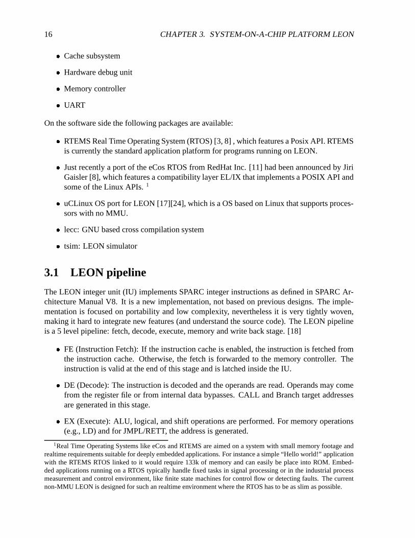
The above figure show a ld (word) and st(word) command on a DCache hit. The load command willtake 1 execution cycle to process, in the execution stage the EAddress will be generated (row 2). Thestore command will take 2 execution stage cycles to process, in the first cycle (row 2) the EAddress isgenerated (that will then move into MAddress of memory stage), in the second cycle (row 3) EData (thevalue to store) is retrieved from the register file. The store will initialize the writebuffer, which will drivethe memory request so that the pipeline can continue operation.
Figure 3.1.1: Load/Store commands
� ME (Memory): Data cache is accessed. For cache read hit, the data will be valid by theend of this stage, at which point it is aligned as appropriate. Store data on a cache hit readout in the E-stage (2 cycle execution stage command) is written to the data cache at thistime.
� WR (Write): The result of any ALU, logical, shift, or cache read operations are writtenback to the register file. [18]
In principle every command takes 5 cycles to finish if no stalls occur, however the decode andexecution stage are multi cycle stages that can take up to 3 cycles, for instance the store double(ldd) command would remain 3 cycles in the execution stage before pipeline continues. Memoryaccess from data cache is initiated through the load (ld), store (st), load alternate (lda), storealternate (sta) and the atomic loadstore (ldst) and swap (swap) commands in the memorystage. Figure 3.1.1 shows a 1 cycle execution stage load (ld), and a 2 cycle execution stage store(st) command.
3.2 Cache subsystem
The LEON processor implements a Harvard architecture with separate instruction and databuses, connected to two independent cache controllers. Both data cache (DCache) and instruc-

18 CHAPTER 3. SYSTEM-ON-A-CHIP PLATFORM LEON
merge
align
EData EAddress MAddress
WB
1
2
3
4
Cachemem
data out
tag out
data out
addr
Memory
data in
hit
Idle Idle
100
Store
Waiting Load
110001
011
Double Load StoreStore pending
3 decode cycles
Load
= pipeline hold
In the above figure address that drives the cachemem comes either from execution stage or from memorystage (1). Both read and write commands share a single writebuffer to issue memory requests (2) thereforeread and write commands have to wait until the writebuffer empties, in which case the pipeline stalls. Ona read the pipeline will of course wait for the result to be returned from memory. On a store the pipelinewill stall until the writebuffer is empty. The memory result will be aligned (3) and is merged into thecurrent cache line (4).
Figure 3.2.1: LEON DCache schematic and state transition diagram
tion cache (ICache) share one single Advanced Microcontroller Bus Architecture (AMBA) Ad-vanced System Performance Bus (ASB) master interface to access the memory controller.
3.2.1 Data cache (DCache)
The LEON DCache is a direct-mapped cache, configurable to 1 - 64 kbyte. It has a one elementwritebuffer that operates in parallel to the pipeline after a store operation has initialized it. Thewrite policy for stores is write-through with no-allocate on write-miss. The data cache is dividedinto cache lines of 8 - 32 bytes. Each line has a cache tag associated with it, containing a tagfield and one valid bit per 4-byte sub-block [18]. A simplified DCache schematic is shown infigure 3.2.1.
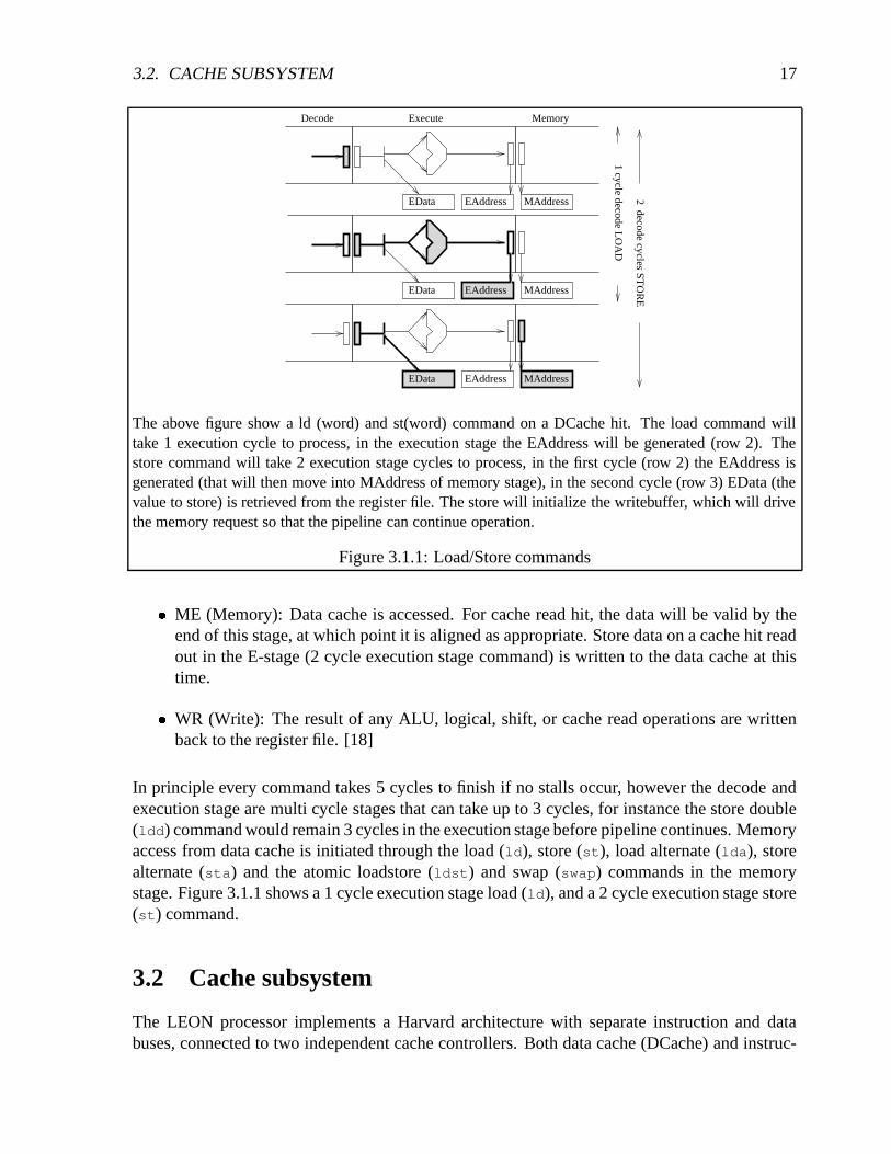
Figure 3.2.2 shows the DCache miss behavior. This part is especially important to under-stand because the MMU’s address translation will have to be done here.
3.2.2 Instruction cache
The LEON instruction cache is a direct-mapped cache, configurable to 1 - 64 kbyte. The in-struction cache is divided into cache lines with 8 - 32 bytes of data. Each line has a cache tagassociated with it consisting of a tag field and one valid bit for each 4-byte sub-block [18]. Asimplified ICache schematic is shown in figure 3.2.3.
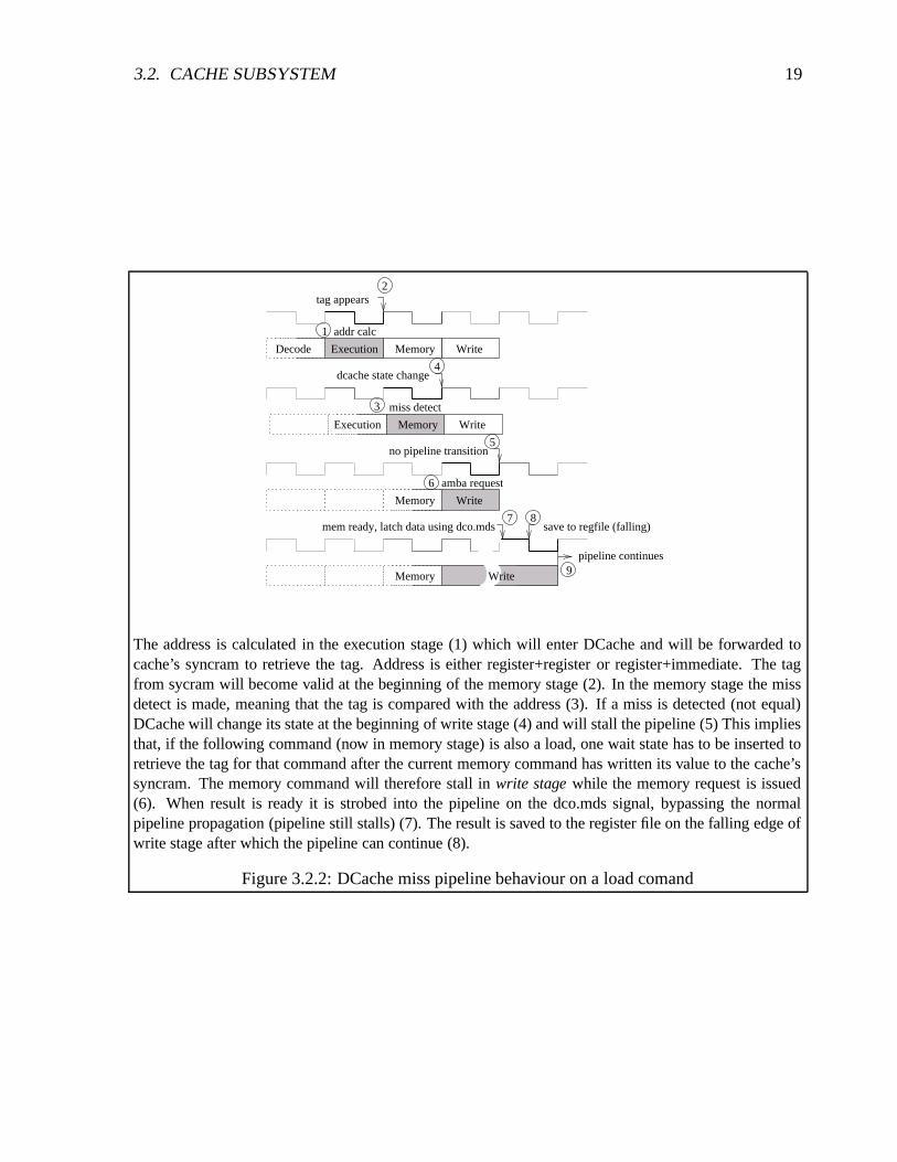
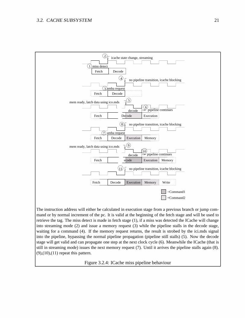
Figure 3.2.4 shows the ICache behavior on a miss. ICache will change into streaming mode,fetching one entire cache line. Because the configurable cache line size is a power of 2 andsmaller than the 4k page size this operation will not cross a page boundary. Therefore only one
3.2. CACHE SUBSYSTEM 19
Memory
amba request
Write
no pipeline transition
Memory
Decode
3
2
1
4
5
6
8
9
7
Write
pipeline continues
save to regfile (falling)mem ready, latch data using dco.mds
Memory Write
miss detect
Execution
dcache state change
Execution Memory Write
addr calc
tag appears
The address is calculated in the execution stage (1) which will enter DCache and will be forwarded tocache’s syncram to retrieve the tag. Address is either register+register or register+immediate. The tagfrom sycram will become valid at the beginning of the memory stage (2). In the memory stage the missdetect is made, meaning that the tag is compared with the address (3). If a miss is detected (not equal)DCache will change its state at the beginning of write stage (4) and will stall the pipeline (5) This impliesthat, if the following command (now in memory stage) is also a load, one wait state has to be inserted toretrieve the tag for that command after the current memory command has written its value to the cache’ssyncram. The memory command will therefore stall in write stage while the memory request is issued(6). When result is ready it is strobed into the pipeline on the dco.mds signal, bypassing the normalpipeline propagation (pipeline still stalls) (7). The result is saved to the register file on the falling edge ofwrite stage after which the pipeline can continue (8).
Figure 3.2.2: DCache miss pipeline behaviour on a load comand

20 CHAPTER 3. SYSTEM-ON-A-CHIP PLATFORM LEON
waddr
R−pc F−pc
1
2
Cachemem
Memory
data in
data out
hit
addr
data out
tag out
addr
10
line end
miss
= streaming
On a ICache miss the ICache will change into streaming mode. The waddr buffer will hold the nextmemory address to retrieve (1). On each command that has been retrieved waddr will be incremented.(2)
Figure 3.2.3: LEON ICache schematic
translation has to be done when changing into streaming mode.
3.2.3 AMBA ASB interface
Data and instruction cache have to share one single AMBA ASB master interface. Serializingthe concurrent ICache and DCache requests is done by the ACache component. A simplifiedASB query is shown in the figure 3.2.
grant
ready
data
AM
BA
data in
data out
Request Wait
addr out
data
addr
req
Cac
he
Figure 3.2: Simplified ASB query
3.2. CACHE SUBSYSTEM 21
miss detect
DecodeFetch
icache state change, streaming
Fetch MemoryDecode WriteExecution
no pipeline transition, icache blocking
Decode
amba request
Fetch
no pipeline transition, icache blocking
ExecutionDecodeFetch
pipeline continuesdecode
mem ready, latch data using ico.mds
Fetch Decode Execution Memory
amba request
no pipeline transition, icache blocking
DecodeFetch
decode
Execution
pipeline continues
Memory
mem ready, latch data using ico.mds
=Command1
=Command2
1
7
9
2
4
3
5
6
8
10
11
The instruction address will either be calculated in execution stage from a previous branch or jump com-mand or by normal increment of the pc. It is valid at the beginning of the fetch stage and will be used toretrieve the tag. The miss detect is made in fetch stage (1), if a miss was detected the ICache will changeinto streaming mode (2) and issue a memory request (3) while the pipeline stalls in the decode stage,waiting for a command (4). If the memory request returns, the result is strobed by the ici.mds signalinto the pipeline, bypassing the normal pipeline propagation (pipeline still stalls) (5). Now the decodestage will get valid and can propagate one step at the next clock cycle (6). Meanwhile the ICache (that isstill in streaming mode) issues the next memory request (7). Until it arrives the pipeline stalls again (8).(9),(10),(11) repeat this pattern.
Figure 3.2.4: ICache miss pipeline behaviour
22 CHAPTER 3. SYSTEM-ON-A-CHIP PLATFORM LEON

Chapter 4
SPARC standard
The LEON integer unit implements the SPARC Architecture Manual V8 standard. This chaptertries to give a brief overview of it’s RISC nature. For the details refer to [21].
4.1 RISC
Other than the CISC architectures, which where developed by commercial companies, the RISCarchitecture emerged from a research and academic surrounding [19]. The RISC key phrasewas coined by the Berkeley RISC I + II project, led by David Patterson at UC Berkeley datingback to 1980. The RISC I architecture later became the foundation of Sun Microsystems’s [13]SPARC V7 standard, commercialized by SPARC International Inc. [20]. Another famous RISCarchitecture that resembles this development is the MIPS machine, developed at Stanford led byJohn Hennessy, later commercialized by MIPS Technologies Inc [15].
4.2 SPARC V8
The current version 8 (V8) of the SPARC standard was first published in 1990 and can bedownloaded from [21]. Like other reduced instruction set (RISC) architectures it’s featuresinclude a fixed size instruction format with few addressing modes and a large register file. Thedistinctive feature of SPARC is it’s “windowed” register file, where the instruction’s source anddestination register addresses are offseted by the “Current Window Pointer” , this way a largepool of fast registers can be accessed, while still keeping the instruction size small.
4.2.1 Register windows
Figure 4.1 illustrates the register windows for a configuration with 8 windows. The registerwindows are divided into 3 parts: ins, local and outs. On a SAVE instruction, which adds 1to the Current Window Pointer (CWP), the current window’s “outs” will get the new window’s“ins”, on a RESTORE, which subtracts 1 from the CWP, it’s vice versa. On the wraparoundpoint one invalid window exist (window 7 in the above figure). This window is marked by theWindow Invalid Mask (WIM). It is invalid because it’s “out” registers would overwrite the “ins”
23

24 CHAPTER 4. SPARC STANDARD
Win
do
w 1
W
indow3
Win
do
w 5
Window 7 (W
IM)
W
ind
ow
2
Window 4
Win
do
w 6
W
indow 0
local
outs
ins
outs
ins
ins
ins
ins
ins
ins
outs
outs
outs
outs
outs
outs
ins local
local
local
local
local
local
local
SAVE
RESTORECWP+1
CWP-1
Figure 4.1: SPARC register windows (taken from [21] p.27)
of it’s neighbor which is not desirable, therefore moving into a invalid marked window willcause a trap. Typically the trap handler will take care of swapping the registers onto the stack.The “local” registers are registers that are visible only to the current function, while the “ins”and “outs” are shared between caller and callee1.
4.2.2 SPARC instruction overview
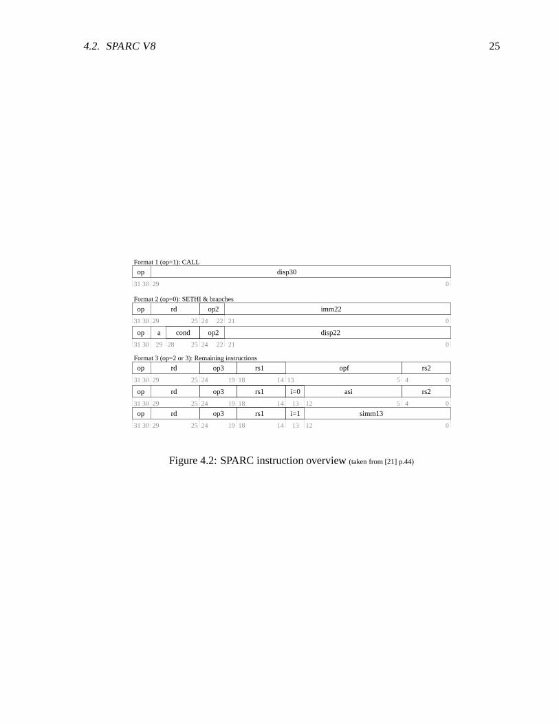
All SPARC instruction are 32 bit wide. For the MMU design mainly instructions for memoryaccess are relevant. For memory access only few “load to register” and “store from register”commands are available. The destination (for stores) and source (for loads) addressing modeis register indirect with an optional offset (either immediate or register). This enables a simplepipeline with only one memory stage. A reference to a absolute memory address will take upto 3 instructions, two instructions for initializing the address register (load lower 13 bit andload upper 19 bit) and one for the memory operation. If a base pointer is already loaded into aregister (like the stack pointer) a reference will take only one instruction if a immediate offsetis used, two instructions if a register has to be first loaded with the offset. Figure 4.2 givesan instruction layout overview. There are 3 main formats: Format 1 represent absolute jumps,format 2 represent the command for initializing the upper part of a 32 bit register (SETHI) andfor conditional branches, format 3 represent the remaining arithmetic and control commands.
1The callee has to issue a SAVE at the beginning and a RESTORE at the end when returning.
4.2. SPARC V8 25
Format 3 (op=2 or 3): Remaining instructions
Format 2 (op=0): SETHI & branches
Format 1 (op=1): CALL
op disp30
op op2a cond disp22
op rd op2 imm22
op rd op3 rs1 simm13
op rd op3 rs1 rs2opf
31 30 29 25 24 2122
31 30 29 0
0
0
0
op rd op3 rs1 rs2i=0 asi
0
4
4
2122242528293031
31 30 29 25 19 18 14 13
51418192425293031
3031 29 25 24 19 18 14 0
24 5
i=1
12
1213
13
Figure 4.2: SPARC instruction overview (taken from [21] p.44)

26 CHAPTER 4. SPARC STANDARD

Chapter 5
SPARC V8 Reference MMU (SRMMU)
The MMU for LEON that is the target of this diploma thesis implements a MMU that is compli-ant to the SPARC Reference MMU (SRMMU): The SPARC Architecture Manual V8[21] doesnot require a MMU to be present, the standard rather specifies a reference MMU in AppendixH that is optional to implemented. However all commercial SPARC V8 implementation followthe SRMMU suggestion. The main features of SRMMU are:
� 32-bit virtual address
� 36-bit physical address
� Fixed 4K-byte page size
� Support for sparse address spaces with 3-level map
� Support for large linear mappings (4K, 256K, 16M, 4G bytes)
� Support for multiple contexts
� Page-level protections
� Hardware miss processing (Table Walk)
The following sections will give an overview. For more information refer to [21].
5.1 SPARC SRMMU translation overview
Figure 5.1 gives an detailed overview of the translation process and the data structures that areinvolved.
The first level of the page table hierarchy is that of the Context Table (1) . It is indexed by theContext Number (CTXNR), a register that is initialized with a unique number that is associatedto each process. On a process switch this register has to be updated1. The 1-4 levels of the page
1The Context Number together with the virtual address form the Cache’s tag, this way cache synonyms areavoided (different processes that use the same virtual address for different physical mappings). The use of theContext Number in the SRMMU suggests that the Caches should be virtually tagged / virtually indexed, which isdescribed in Chapter 6 in more detail.
27

28 CHAPTER 5. SPARC V8 REFERENCE MMU (SRMMU)
035 12 11
Physical Page Number Offset
8
Physical Page Number
0
C M R ACC ET
1467 5 231
8 0
ET
1467 5 231
Page Table Pointer
Context Number
08
2
1
3
4
17 12 11
Level 1 Offset
1824 2331 0
Level 2 Level 3
PTE
PTE(page table entry)
PTD
(context table pointer)
(context number)
PTD/PTEPTD/PTE
(page table descriptor)
CTP
CTXNR
VAddr
PAddr
31
Context Table Pointer rsvd
11011 2 0
align
PTD/PTE
Figure 5.1: Translation overview
table hierarchy (2) are indexed through the different parts of the virtual address. If a Page TableDescriptor (PTD) is found when indexing into the Page Table, the next level is traversed, if aPage Table Entry (PTE) is found the traversal is completed. PTE and PTD are distinguished bythe ET field (3), where ET=1 indicates PTD and ET=2 indicates PTE, ET=0 indicates a missingentry (page fault). Level 1 PTE (context) map to 4 GB, level 2 PTE (region) map to 16 MB, level3 PTE (segment) map to 256k and level 4 PTE (page) map to 4k. The PTE entry includes thePhysical Page Number and additional flags for protection, cache-ability and referenced/modifiedaccounting. The physical address (4) that is the result of the translation of the MMU is formedout of the Physical Page Number and the Offset (the sizes vary depending on the page tablehierarchy level).
5.2 ASI: Alternate Space Instructions
The privileged versions of the load/store integer instructions (ld/st), the load/store alternateinstructions (lda/sta), can directly specify an arbitrary 8-bit address space identifier (ASI) forthe load/store data access. The privileged alternate space load/store instructions take the form:“lda [addr] asi_ident,%r” and “sta %r,[addr] asi_ident”, where asi_ident is the 8 bitASI identifier. The address and the value (in case of a store) are interpreted in a specific waythat differ for each ASI identifier2. The privileged load/store alternate instructions can be usedby supervisor software to access special protected registers, such as MMU, cache control, and
2For instance for ASI identifiers “DCache_flush” on a store to any address DCache is flushed. In other ASIidentifier spaces addresses are mapped to special registers, that can be stored or loaded just like normal memory.
5.2. ASI: ALTERNATE SPACE INSTRUCTIONS 29
processor state registers, and other processor or system dependent values [21]. For the MMUthe SPARC Architecture Manual V8 suggests the ASI “MMU register” (0x4) , ASI “MMUflush/probe” (0x3), ASI “MMU bypass” and a optional ASI “MMU diagnostic access I/D TLB”(0x7). For fine grade cache flushing (flushing depending on ctx number and a virtual addresspattern) five additional “I/DCache flush” ASIs are suggested.
5.2.1 ASI:MMU register access
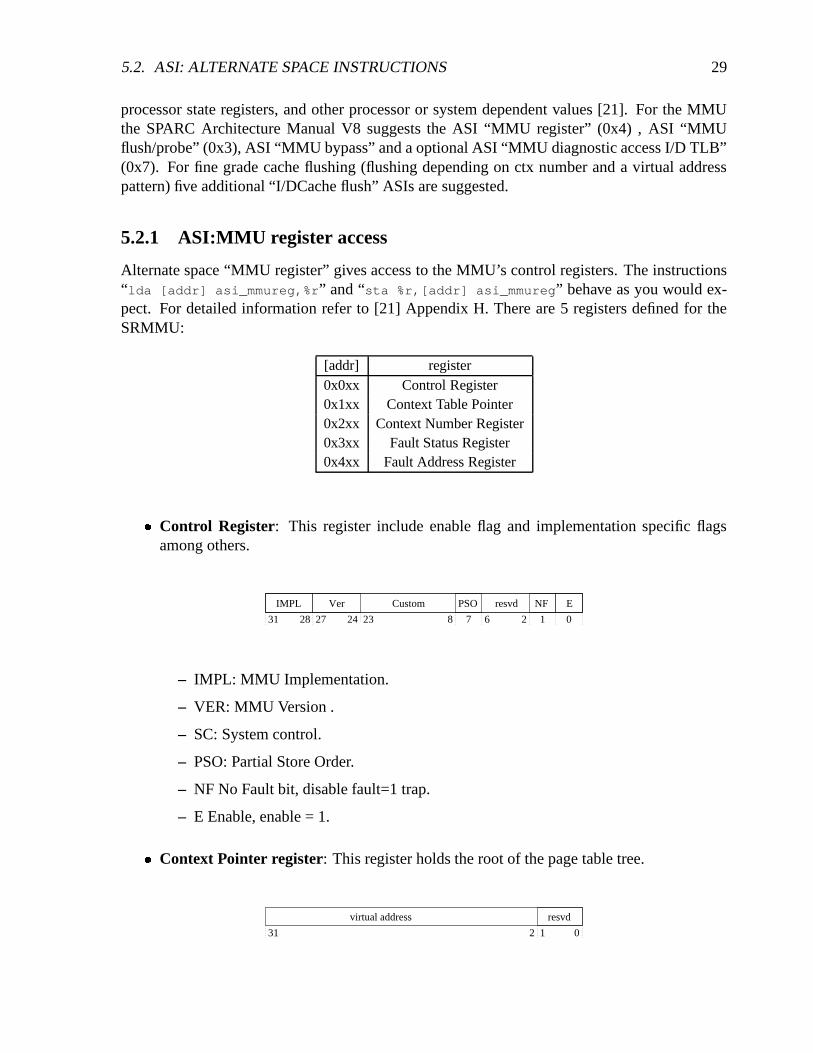
Alternate space “MMU register” gives access to the MMU’s control registers. The instructions“lda [addr] asi_mmureg,%r” and “sta %r,[addr] asi_mmureg” behave as you would ex-pect. For detailed information refer to [21] Appendix H. There are 5 registers defined for theSRMMU:
[addr] register0x0xx Control Register0x1xx Context Table Pointer0x2xx Context Number Register0x3xx Fault Status Register0x4xx Fault Address Register
� Control Register: This register include enable flag and implementation specific flagsamong others.
NFPSO Eresvd CustomIMPL Ver
01678 22324272831
– IMPL: MMU Implementation.
– VER: MMU Version .
– SC: System control.
– PSO: Partial Store Order.
– NF No Fault bit, disable fault=1 trap.
– E Enable, enable = 1.
� Context Pointer register: This register holds the root of the page table tree.
resvd
02 131
virtual address

30 CHAPTER 5. SPARC V8 REFERENCE MMU (SRMMU)
� Context Number register: This register stores the context number of the running pro-cess. It will form the offset into the context table.
031
Context Number
� Fault status register: This register holds the status of the MMU on a exception (i.e. pagefault).
01231
reserved LEBE
1718 10 9 8 7 5 4
AT FT FAV OW
– EBE: unused
– L: The Level field is set to the page table level of the entry which caused the fault:
L Level0 Entry in Context Table1 Entry in Level-1 Page2 Entry in Level-2 Page3 Entry in Level-3 Page
– AT: The Access Type field defines the type of access which caused the fault:
AT Access Type0 Load from User Data Space1 Load from Supervisor Data Space2 Load/Execute from User Instruction Space3 Load/Execute from Supervisor Instruction Space4 Store to User Data Space5 Store to Supervisor Data Space6 Store to User Instruction Space7 Store to Supervisor Instruction Space
– FT: The Fault Type field defines the type of the current fault:

5.2. ASI: ALTERNATE SPACE INSTRUCTIONS 31
FT Fault type0 None1 Invalid address error2 Protection error3 Privilege violation error4 Translation error5 Access bus error6 Internal error7 Reserved
� Fault address register: This register holds the virtual address that caused the exception:
031
virtual address
5.2.2 ASI:flush/probe
Alternate space “flush/probe” gives access to the MMU’s translation process and the TLB. Aread access to ASI “flush/probe” will initiate a probe operation, either returning the PTE orzero3 - a write access will initiate a flush operation, that will remove entries form the TLB. Theflush/probe criteria is coded into the write/read address and has different meanings for flush andprobe. It has the following format:
31 0
Virtual Flush Probe Address reserved
78
type
1112
� Virtual Flush/probe address: The index part of the virtual address.
� Type:
Type Probe Flush0 (page) probe until Level-3 entry flush Level-3 PTE
1 (segment) probe until Level-2 entry flush Level-2 & 3 PTE/PTDs2 (region) probe until Level-1 entry flush Level-1, 2 & 3 PTE/PTDs3 (context) probe until Level-0 entry flush Level-0, 1, 2, & 3 PTE/PTDs4 (entire) probe until Level-n entry flush all PTEs/PTDs
5 - 0xF none
3Probe operation will return the PTE of the page table hierarchy, not the physical address the is coded into thePTE. The probe operation can also be done in software, using the ASI “MMU physical address pass through” andtraversing the page table hierarchy by hand. In fact the probe operation is rarely used.

32 CHAPTER 5. SPARC V8 REFERENCE MMU (SRMMU)
5.2.2.1 flush
A flush operation takes the form “sta %r, [addr] asi_flush_probe”, where data suppliedin %r is ignored and addr forms the flush criteria (see above). Entries from the TLB satisfy thegiven criteria are flushed. For detailed information refer to [21] Appendix H, p. 250.
5.2.2.2 probe
A probe operation takes the form “lda [addr] asi_flush_probe,%r”, where addr forms theprobe criteria (see above) . The return value is either the PTE or zero. For detailed informationrefer to [21] Appendix H, p. 250.
Level 0 Level 1 Level 2 Level 3probe Type 2 3 0 1 2 3 0 1 2 3 0 1 2 3 0 1
0(page) 0 0 0 => 0 0 0 => 0 0 0 => * 0 * 01(segment) 0 0 0 => 0 0 0 => * 0 * * -2(region) 0 0 0 => * 0 * * - -3(context) * 0 * * - - -4(entire) * 0 0 => * 0 0 => * 0 0 => * 0 0 0
5-0xf undefined
*=value, 0=zero, “=>”= follow [21]
5.2.3 ASI: MMU diagnostic access I/D TLB
Alternate space “MMU diagnostic access I/D TLB” gives direct read/write access to the TLB.This ASI is not intended for system operation but for system debugging only. It is not requiredto be implemented. The SRMMU specification gives a suggestion of the coding of the ad-dress/data supplied by the “lda [addr] asi_iodiag,%r” and “sta %r,[addr] asi_iodiag”command, however these are highly implementation specific. The method implemented in thisdiploma thesis simply reads out the whole TLB entries content to ram using the AMBA interfacealready connecting the TLB for write-back of page table entries who’s referenced or modifiedbits has changed. This ASI can be removed when system has proven to works properly. Writeoperation on TLB is not supported.
5.2.4 ASI: MMU physical address pass through
Alternate Load/Store with the ASI “MMU physical address pass through” bypass the MMUtranslation, i.e. this can used to modify the page table hierarchy on bootup. The original SPARCsuggestion for this ASI is 0x20-0x2f. For detailed information refer to [21] Appendix I, p. 267.
5.2.5 ASI: I/DCache flush
This ASI affects the cache itself (not the TLB). This ASI is used by Linux and is thus addedto the DCache controller’s ASI decoder. A alternate Store with the Alternate Space Identifier
5.2. ASI: ALTERNATE SPACE INSTRUCTIONS 33
“I/DCache flush” will flush I/DCache entries given a specific criteria. For detailed informa-tion refer to [21] Appendix I, p. 266. In the current implementation any alternate store to ASI“I/DCache flush” will flush the whole I/DCache, a future enhancement could be the implemen-tation of a fine grade flush that is suggested by the SPARC standard.

34 CHAPTER 5. SPARC V8 REFERENCE MMU (SRMMU)
Chapter 6
Design options
There are several possibilities for implementing a MMU for LEON, each of which would haveto be integrated into a different place of the current design. For the cache/MMU integration anyof the three alternatives, “physically tagged and physically indexed” (PTPI), “virtually taggedand physically indexed” (VTPI), and “virtually tagged and virtually indexed” (VTVI) has itsdrawbacks and advantages that are discussed in the following chapter. The SRMMU actuallysuggests to use a the VTVI design by introducing the Context Number register, however also aPTPI or VTPI design could be implemented that complies to the SRMMU standard.
In a VTVI design there are again 2 choices to choose from: virtual writebuffer (translationafter initialization of writebuffer) or physical writebuffer (translation before initialization ofwritebuffer). The VTVI design with a physical writebuffer and a combined I/DCache TLB isthe most simple design to implement.
6.1 Physically tagged / physically indexed (PTPI)
On a PTPI design one TLB lookup has to be made on every cache access. This requires the TLBlookup to be integrated into the pipeline to get reasonable performance. In a PTPI design sharedpages among different processes are possible (with any virtual address mapping), which meanssharing of cache line among different tasks is possible. Cache snooping is possible1. A PTPIintegration is shown in figure 6.1.
Implementing such a scheme into LEON would be difficult because it would mean in fact torewrite the pipeline. An advantage would be that DCache and ICache could be left unchanged,with snooping enabled.
6.2 Physically tagged / virtually indexed (PTVI)
The PTVI design combines the physical with the virtual cache design: The drawback of a purephysical cache is that the TLB lookup has to be done before every cache access, the drawbackof s pure virtual cache design is that context information has to be added to avoid the synonym
1In Cache Snooping the AMBA Bus is constantly checked to see weather another AMBA Bus Master is modi-fying a memory location which is stored in the Cache
35

36 CHAPTER 6. DESIGN OPTIONS
data cacheinstruction
cache
icache tlb
DEFE EX ME WBdcache
tlb
Figure 6.1: Pipeline with physically tagged and physically indexed cache
problem (see section 6.3). The PTVI design still has to do a TLB lookup on every cache access,but because the cache index is virtual the tag retrieval can be initiated right away while theTLB lookup is done in parallel. Because the tag is physical no synonyms can occur, thereforeno context information is needed. This also means that sharing cache line among differentprocesses is possible (yet the virtual addresses mappings have to be equal2). Cache snooping isnot possible. Therefore on a memory access by another AMBA master Cache integrity has to bemaintained my software. A PTVI integration is shown in figure 6.2.
ME WBEXDEFE
data
tag
pysical tag
hit
tlbdcache data cache
virtual index
data
tag
instruction cache
pysical tag
hit
icache
tlb
virtual index
Figure 6.2: Pipeline with virtually tagged and physically indexed cache
Because the TLB lookup has to be done in one cycle (until the tag arrives) either a dual portsyncram or a split instruction/data cache has to be implemented so that instruction/data cachecan work in parallel. Integration could be done in ICache and DCache with minor changes inthe cache - pipeline inter-working.
2Cache lines that store the Linux kernel could be shared by all processes , because the kernel is compiled to afixed vaddress.

6.3. VIRTUALLY TAGGED / VIRTUALLY INDEXED (VTVI) (SRMMU) 37
6.3 Virtually tagged / virtually indexed (VTVI) (SRMMU)
The main advantage of a VTVI design is that the TLB lookup is positioned after the cache. Thisleaves the pipeline - cache inter-working unchanged. Only on a a cache miss the TLB lookupis initiated. Because two virtual addresses can point to the same physical address (synonym) thecache tag has to be extended with the context number so that each address of different virtualaddress spaces of different processes are distinct. This leads to multiple cache lines if the samephysical address is referenced by multiple contexts, which is a drawback. Cache snooping is notpossible. A VTVI integration is shown in figure 6.3.
data cacheinstruction
cache
ME WBEXDEFE
memory
ctrl
amba bus
amba master
combined instruction−data tlb
Figure 6.3: Pipeline with virtually tagged and virtually indexed cache
The VTVI design is proposed by the SRMMU. It is the easiest design to implement becauseit is fairly sequential.
6.3.1 Writebuffer
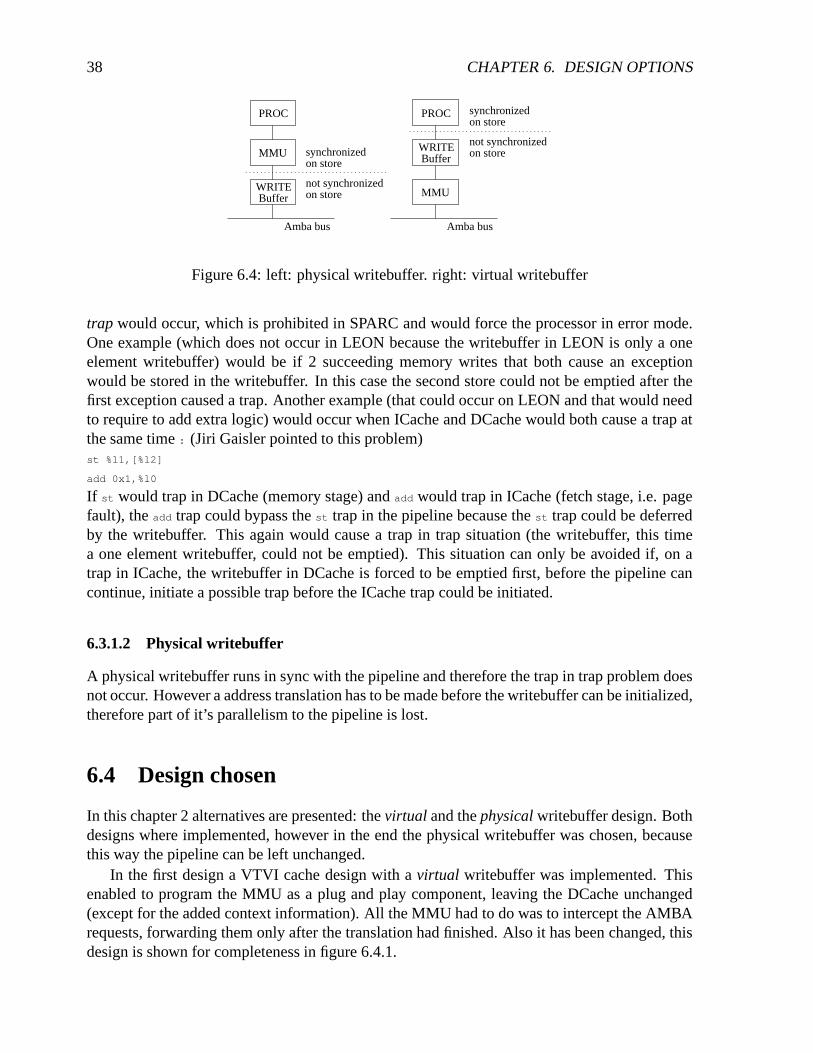
In LEON on a store command the writebuffer (if empty) will be initialized and will work inparallel to the pipeline. When using a VIVT cache the writebuffer can be initialized by virtualaddresses, in which case the address translation is done after initializing the writebuffer, or asa physical writebuffer, in which case the translation is done before initializing the writebuffer.The difference of a physical and a virtual writebuffer is shown in figure 6.4.
6.3.1.1 Virtual writebuffer
A virtual writebuffer implies that on a MMU exception the pipeline state can not be recoveredbecause a exception will take place after the pipeline has already continued for some time (theexception is deferred). Without extra precautions this leads to some situations where a trap in
38 CHAPTER 6. DESIGN OPTIONS
PROC
WRITEBuffer
MMU
not synchronizedon store
on storesynchronized
Amba bus
PROC
WRITEBuffer
MMU
not synchronizedon store
on storesynchronized
Amba bus
Figure 6.4: left: physical writebuffer. right: virtual writebuffer
trap would occur, which is prohibited in SPARC and would force the processor in error mode.One example (which does not occur in LEON because the writebuffer in LEON is only a oneelement writebuffer) would be if 2 succeeding memory writes that both cause an exceptionwould be stored in the writebuffer. In this case the second store could not be emptied after thefirst exception caused a trap. Another example (that could occur on LEON and that would needto require to add extra logic) would occur when ICache and DCache would both cause a trap atthe same time : (Jiri Gaisler pointed to this problem)st %l1,[%l2]
add 0x1,%l0
If st would trap in DCache (memory stage) and add would trap in ICache (fetch stage, i.e. pagefault), the add trap could bypass the st trap in the pipeline because the st trap could be deferredby the writebuffer. This again would cause a trap in trap situation (the writebuffer, this timea one element writebuffer, could not be emptied). This situation can only be avoided if, on atrap in ICache, the writebuffer in DCache is forced to be emptied first, before the pipeline cancontinue, initiate a possible trap before the ICache trap could be initiated.
6.3.1.2 Physical writebuffer
A physical writebuffer runs in sync with the pipeline and therefore the trap in trap problem doesnot occur. However a address translation has to be made before the writebuffer can be initialized,therefore part of it’s parallelism to the pipeline is lost.
6.4 Design chosen
In this chapter 2 alternatives are presented: the virtual and the physical writebuffer design. Bothdesigns where implemented, however in the end the physical writebuffer was chosen, becausethis way the pipeline can be left unchanged.
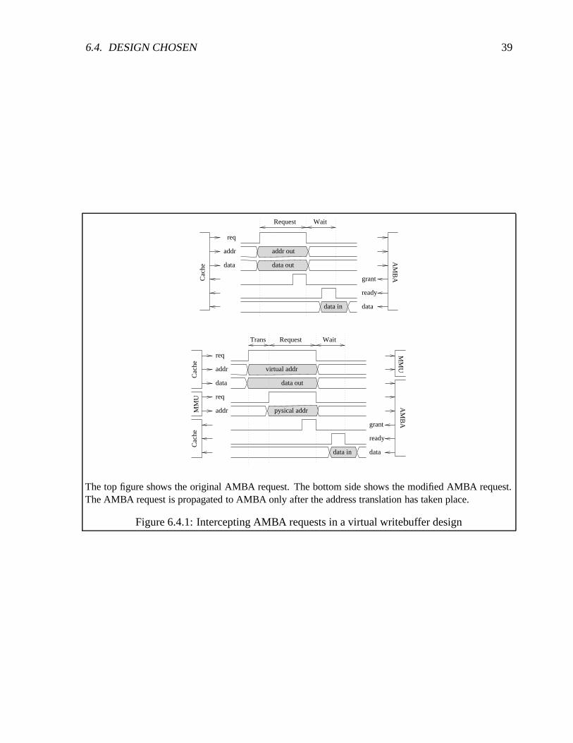
In the first design a VTVI cache design with a virtual writebuffer was implemented. Thisenabled to program the MMU as a plug and play component, leaving the DCache unchanged(except for the added context information). All the MMU had to do was to intercept the AMBArequests, forwarding them only after the translation had finished. Also it has been changed, thisdesign is shown for completeness in figure 6.4.1.
6.4. DESIGN CHOSEN 39
grant
ready
data
AM
BA
data in
data out
Request Wait
addr out
data
addr
req
Cac
he
virtual addr
data out
Cac
heC
ache
data in
Request Wait Trans
grant
ready
data
AM
BA
addr
MM
U
MM
U
addr
req
data
req
pysical addr
The top figure shows the original AMBA request. The bottom side shows the modified AMBA request.The AMBA request is propagated to AMBA only after the address translation has taken place.
Figure 6.4.1: Intercepting AMBA requests in a virtual writebuffer design

40 CHAPTER 6. DESIGN OPTIONS
idle
tlbprobe
tlbflush
tlbprobe2
mmudiag
asi_itag_idata
loadpend
wread
wread_trans
wwrite_trans
wwrite
dlbwrite
cache misson
idleRead op
ASI spaceWrite op
loadpend
loadpend
The state machine in figure 6.4.2 shows the various ASI space transitions on the right side, on the leftside the read and write operations perform a translation in state “wread_trans” and “wwrite_trans” beforeinitializing the writebuffer. State “wread” will wait for the result to be returned (stalling the pipeline), ifa memory access command follows immediate after the current command, the loadpend state is inserted.State “write” will initialize the writebuffer with the translated address and will return immediately.
Figure 6.4.2: New DCache state machine
The virtual writebuffer design gave rise to the trap in trap problem. This could be fixedwith changes in the pipeline, however instead in the second run the VTVI cache design with aphysical writebuffer was chosen. In this case the DCache and ICache had to be reprogrammed.
6.4.1 VTVI DCache, physical writebuffer (DCache.vhd)
The DCache has been rewritten. It now implements a VTVI cache with a physical writebuffer,context information was added to the tag field. The ASI spaces decoder was extended to sup-port “flush/probe”, “MMU register”, “MMU bypass”, “I/D flush” and and “Diagnostic access”accesses. A DCache state diagram is shown in figure 6.4.2.
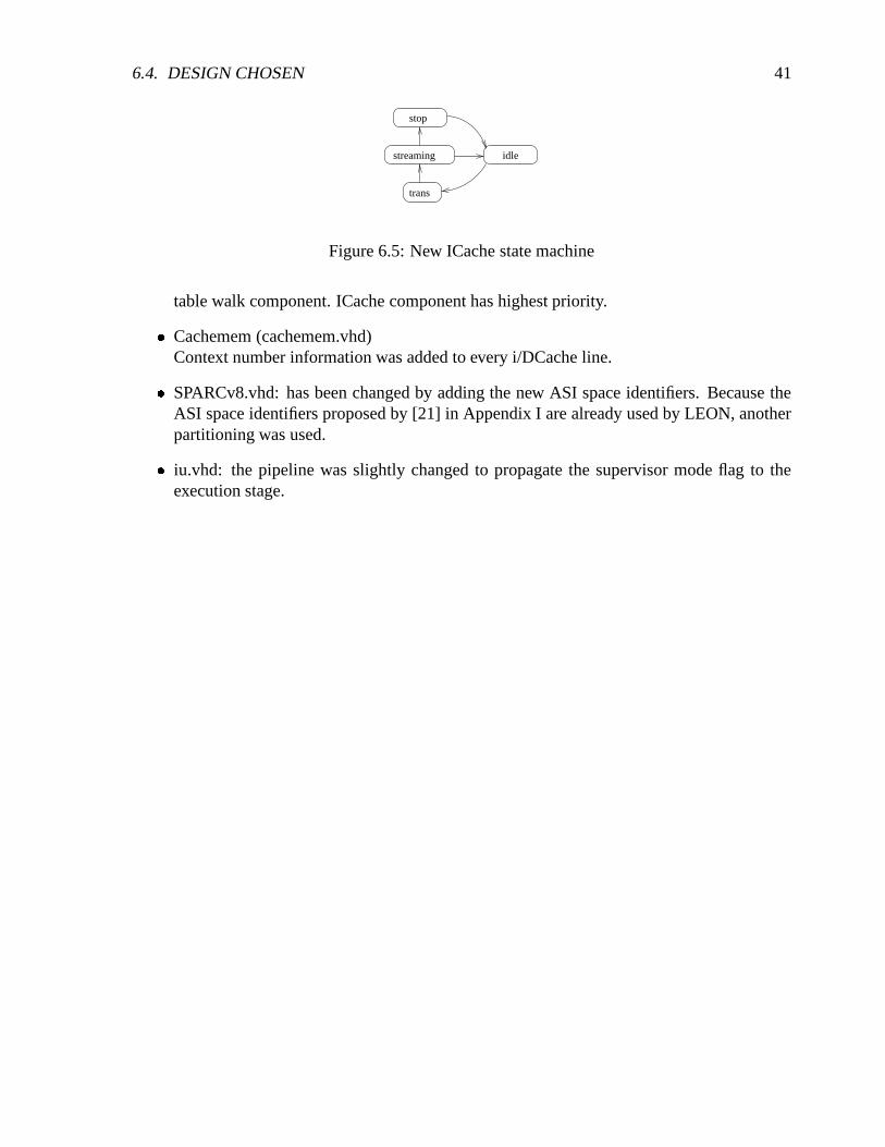
6.4.2 VTVI ICache (ICache.vhd)
The data cache has been rewritten. It now implements a VTVI cache, context information wasadded to the tag field. The address translation is done before entering the ICache’s streamingmode. A ICache state diagram is shown in figure 6.5.
6.4.3 Other changes made to LEON� AMBA interface (acache.vhd)
The AMBA master interface was rewritten and arbiters between ICache, DCache and the
6.4. DESIGN CHOSEN 41
streaming idle
stop
trans
Figure 6.5: New ICache state machine
table walk component. ICache component has highest priority.
� Cachemem (cachemem.vhd)Context number information was added to every i/DCache line.
� SPARCv8.vhd: has been changed by adding the new ASI space identifiers. Because theASI space identifiers proposed by [21] in Appendix I are already used by LEON, anotherpartitioning was used.
� iu.vhd: the pipeline was slightly changed to propagate the supervisor mode flag to theexecution stage.

42 CHAPTER 6. DESIGN OPTIONS

Chapter 7
43

44 CHAPTER 7. MMU DESIGN COMPONENTS
MMU design components
WriteBuffer
TLBCAM
TLBCAM
TLBCAM
TLBCAM
pte writeback/diag
bufferbuffer
Syncram
LRU
Decode Fetch Execute Memory WritePipeline 1
2
3
4
5
6
7
8
9
10
11
Flus
h/Pr
obe/
diag
diag
nost
ic a
cces
s
bypa
ss
Tra
nsla
tion
Tra
nsla
tionby
pass
Tab
le W
alk
update on miss
Tab
le L
ooka
side
Buf
fer
Mem
ory
Man
agem
ent U
mit
hit
miss
DC
ache
to A
MB
A b
us
to A
MB
A b
us
Mem Ctrl
Amba bus
ICac
he
fault/datafault/datavaddr vaddr
padd
rpaddr paddr
faul
t
faul
t
faul
t
Figure 7.1: MMU schematic

7.1. FUNCTIONAL OVERVIEW 45
Figure 7.1 gives an overview of the MMU as a whole. It’s individual components (MMU,TLB, TLBCAM, Table Walk, LRU) will be described in the next chapter in more detail. Thefigure tries to visualize the data paths in a simplified way: ICache and DCache receive virtualaddresses for translation (1), in addition DCache will also handle the various ASI identifiersfor the MMU. “MMU Flush/Probe” and “MMU I/D diagnostic access” will be forwarded tothe MMU (2), the other ASI identifiers are handled inside DCache. The translation operationcan be bypassed in case the MMU is disabled or if ASI “MMU physical address pass through”is used. In this case the writebuffer of DCache and the instruction address buffer in ICache(3) will be initialized immediately and an AMBA request will be issued. In case of MMUis enabled a translation will be requested from ICache and DCache. If a ICache and DCacherequest is issued at the same time they are serialized, the request that has to wait will be bufferedin the meantime (4). ICache’s translation request and DCache’s translation, flush/probe and“diagnostic access” requests will then be issued serially to the Table Lookaside Buffer (TLB) (5).The translation operation, flush operation and probe operation will be described in the followingsection (“Functional overview”). The “diagnostic access” operation is already been described insection 5.2.3. The translation, flush and probe operation will initiate different match operationson the TLBCAM (6) that will assert a hit on success (7). In case of translation operation andprobe operation a miss will initiate a Table Walk that will traverse the Page Table Hierarchy.After the Page Table Entry is retrieved from memory the new entry will be stored in TLBCAM(tag) and syncram (data). The TLBCAM entry that is going to be replaced (which is determinedby the LRU component) will be checked for memory synchronization (ref/modified bit changed)(8). After completion the result is returned to the MMU from the TLB: a translation operationwill return the physical address that is used in DCache to initialize the Writebuffer (9) and inICache to initialize the instruction address buffer (10), that is used for increment in streaming. Aprobe operation will return the probed Page Table Entry. A translation operation will also checkfor permissions, on a protection or privilege violation a exception is raised (11). DCache/ICacheand Table Walk AMBA requests are handled using one single AMBA bus master interface (12).
Another alternative view is given in figure 7.2 that visualizes the translation process as apipeline, with 4 stages, “Fetch”, “Table Lookaside Buffer”, “Table Walk” and “Memory Re-quest”. This figure is only for making the translation concept explicit. 1
7.1 Functional overview
The three main MMU operations are: translation, flush and probe. Each of these operations isdescribed:
� Translation operation on a TLB hit is shown in figure 7.1.1.
1In the pipeline schematic figure a zero wait state translation would be realized by feeding in translation ad-dresses while cache hit check is made. The pipeline propagation from “Table Lookaside Buffer” to “Table Walk”(in case of a miss) or “Memory Request” (in case of a hit) would be blocked if the cache asserted hit (no translationneeded). Either DCache or ICache translation request would be allowed to perform such a pre-translation.
In case of a physical writebuffer the writebuffer is in sync with the pipeline. Therefore ICache and DCache willonly issue one translation request at a time. In case of a virtual writebuffer, where the writebuffer is not in syncwith the integer unit pipeline (translation can be deferred) multiple DCache translation requests can be waiting in aqueue. Therefore a MMU pipeline would make sense only for a virtual writebuffer design.

46 CHAPTER 7. MMU DESIGN COMPONENTS
ctrldata
ctrldata
Table
Walk
ireq
dreq
datactrl
ctrldata
TLB
addr mux
datactrl
datactrl
ctrldata
ctrlctrl
datadata
Fetch Table Lookaside Buffer Table Walk Memory Request
Serialize Address translation to Amba
Figure 7.2: Pipeline view
LRU
Syncram
tlbcam
addr
MMU
signal hit (hold=0)virtual address register physical address
physical address
I/DCache
touch
1
2
3
4
At rising edge the virtual address enters TLB (1). It is matched concurrently by all TLB entries. Eachcan generate a hit signal, only one element per match operation is expected to raise the hit signal, thatis used to form the syncram address (2), if multiple hit signals are raised the result is unspecified. Theentry that signalled a hit will be marked in the Least Recently Used (LRU) component (3). If a hit hasoccurred the hold signal will be deasserted, physical address of the translation will be valid at the endof the following cycle and will be registered (4). The following is not shown in the above figure: Thepermission flags are checked against the information given by I/DCache: supervisor access, ICache orDCache access and read or write access. On a protection or privilege violation the fault signal is raised.Also the referenced/modified bits of the hit entry is updated. It will not be synchronized with memoryuntil the entry is flushed or replaced.
Figure 7.1.1: TLB on a hit
� Translation operation on a TLB miss is shown in figure 7.1.2.
� The TLBCAM address generation is shown in figure 7.1.3.
� Probe operation on a TLB hit/miss is shown in figure 7.1.4.
� Flush operation is shown in figure 7.1.5.

7.1. FUNCTIONAL OVERVIEW 47
tlbcam
Syncram
LRU
Syncramcheckmodified
register physical address (hold=0)
physical address
MMU
virtual address
TW
signal miss (hold=1)
AMBA writeback
Table walk
TW
miss
Table walk + AMBA finished
I/DCache
tlb match
mem synchronisation
3
4
1
2
On a TLB miss the Table Walk (TW) is initialized (1). Both the table walk in the TW component and theAMBA writeback operation of the TLB component use one single interface to the AMBA interface of theAMBA master (acache.vhd). The next update position is determined by the Least Recently Used (LRU)component. If the referenced/modified bit of the PTE of the TLB entry that is going to be replaced hasto be synchronized with memory the PTE will be retrieved from syncram and will be updated in memorythrough the AMBA interface (2). When the Table Walk finishes the retrieved PTE is stored in syncramand the corresponding TLB entry is initialized (3). After another cycle the translated physical addressis valid (4). The following is not shown in the above figure: In addition the PTE’s physical memoryaddress is stored so that on a writeback operation (when synchronizing the PTE’s ref/modified flag) thePage Table Hierarchy has not to be traversed. Access permissions are checked.
Figure 7.1.2: TLB on a miss

48 CHAPTER 7. MMU DESIGN COMPONENTS
hit 1 hit 0hit 2hit 3hit 4hit 5
tag−cam
2+3+6+7+10+...
1+3+5+7+9+...
4+5+6+7+12+...
data
−ra
m a
ddre
sshi
t
syncram
data−
The TLB’s tags are stored in fast registers, the associated page table entry is stored in syncram. Each TLBentry can assert a hit signal that generate the syncram address of the associated page table entry through aor-tree, which is shown in the above figure: for instance bit 0 of the syncram address is formed by or-ingthe hit signal of entry 1+3+5+... .This design was chosen to save hardware resources and to be able tostill run a minimal MMU on a XSV300 board. Future implementations could implement the data part inregisters too, which would simplify the design but increase hardware cost. On a hit the syncram addressto be valid at the end of the cycle, the page table entry will appear from syncram after the start of thenext clock cycle and can therefore only be registered at the end of the second cycle after the TLB querywas received. The registration is done in the MMU component. In the current implementation the wholetranslation operation on a TLB hit will take 2 cycles to process.
Figure 7.1.3: TLB hit logic
tlbcam
signal finished (hold=0)
1
2
MMU
DCache
TW
Table walk
miss
tlb match
probe miss
probe hit PTE/0
PTE/0
probe virtual address
The probe operation is initiated through a read access with ASI identifier “MMU flush/probe”. A probeoperation will retrieve a PTE from a given virtual address pattern. On a probe operation first the TLBCAMprobe match operation is done (1) (which is different to the translation match operation). If a hit occurseither PTE or zero is returned. If no hit occurred the Table Walk is initiated (2) and either a PTE entry orzero is returned. ( see Section 5.2.2 for detailed description).
Figure 7.1.4: Probe operation with TLB hit/miss

7.1. FUNCTIONAL OVERVIEW 49
1
n
n−1
2
1
n
n−1
2
signal finished (hold=0)
2 31 4
TW
AMBA writeback
tlbcams
AMBA finished
flush virtual address
modified
hit
not m
odif
ied
hit+
mis
smod
ifie
d
DCache
MMU
tlbcams
Invalidate tlbcamhi
t+
tlbcam 2 tlbcam 3 tlbcam ntlbcam 1
The flush operation is initiated through a write access with ASI identifier “MMU flush/probe”. The flushoperation in the current implementation will take at least one clock cycle per TLB entry, to perform aflush match operation (which is different to translation match and probe match operation). If memorysynchronization is needed additional cycles for the AMBA request are needed. At the end one cycle isneeded to invalidate the matched TLB entries of the flush operation. TLB entries are checked one byone, First a hit against the virtual flush address (Section 5.2.2) is generated. In case of a hit and if thereferenced/modified flags have been changed, the entry is written back to memory. This is shown in theabove figure, where 3 examples are shown: (1) TLBCAM 1 signals a hit and that it needs synchronization,and therefore a AMBA writeback operation is started. (2) TLBCAM 2 signals a hit but does not needsynchronization and therefore AMBA writeback operation is not started. (3) TLBCAM 3 has not hit atall. At the last cycle all entries that have hit are invalidated. In the example this would be entry 1 and 2,entry 3 would be left valid (4).
Figure 7.1.5: Flush operation
50 CHAPTER 7. MMU DESIGN COMPONENTS
7.2 Component Overview
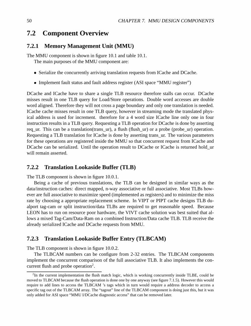
7.2.1 Memory Management Unit (MMU)
The MMU component is shown in figure 10.1 and table 10.1.The main purposes of the MMU component are:
� Serialize the concurrently arriving translation requests from ICache and DCache.
� Implement fault status and fault address register (ASI space “MMU register”)
DCache and ICache have to share a single TLB resource therefore stalls can occur. DCachemisses result in one TLB query for Load/Store operations. Double word accesses are doubleword aligned. Therefore they will not cross a page boundary and only one translation is needed.ICache cache misses result in one TLB query, however in streaming mode the translated phys-ical address is used for increment. therefore for a 4 word size ICache line only one in fourinstruction results in a TLB query. Requesting a TLB operation for DCache is done by assertingreq_ur. This can be a translation(trans_ur), a flush (flush_ur) or a probe (probe_ur) operation.Requesting a TLB translation for ICache is done by asserting trans_ur. The various parametersfor these operations are registered inside the MMU so that concurrent request from ICache andDCache can be serialized. Until the operation result to DCache or ICache is returned hold_urwill remain asserted.
7.2.2 Translation Lookaside Buffer (TLB)
The TLB component is shown in figure 10.0.1.Being a cache of previous translations, the TLB can be designed in similar ways as the
data/instruction caches: direct mapped, n-way associative or full associative. Most TLBs how-ever are full associative to maximize speed (implemented as registers) and to minimize the missrate by choosing a appropriate replacement scheme. In VIPT or PIPT cache designs TLB du-alport tag-cam or split instruction/data TLBs are required to get reasonable speed. BecauseLEON has to run on resource poor hardware, the VIVT cache solution was best suited that al-lows a mixed Tag-Cam/Data-Ram on a combined Instruction/Data cache TLB. TLB receive thealready serialized ICache and DCache requests from MMU.
7.2.3 Translation Lookaside Buffer Entry (TLBCAM)
The TLB component is shown in figure 10.0.2.The TLBCAM numbers can be configure from 2-32 entries. The TLBCAM components
implement the concurrent comparison of the full associative TLB. It also implements the con-current flush and probe operation2.
2In the current implementation the flush match logic, which is working concurrently inside TLBE, could bemoved to TLBCAM because the flush operation is done one by one anyway (see figure 7.1.5). However this wouldrequire to add lines to access the TLBCAM ’s tags which in turn would require a address decoder to access aspecific tag out of the TLBCAM array. The “tagout” line of the TLBCAM component is doing just this, but it wasonly added for ASI space “MMU I/DCache diagnostic access” that can be removed later.

7.3. POSSIBLE FUTURE OPTIMIZATIONS 51
7.2.4 Table Walk (TW)
The TW component is shown in figure 10.0.4.The main functions of the Table Walk component are:
� Perform a table walk on normal translation
� Perform a table walk on a probe operation
� AMBA interface, used for writeback operation of modified page table entries
The Table Walk component will traverse the page table hierarchy by issuing memory requeststo the AMBA interface. The table walk is finished when a PTE is accessed, a invalid page tableentry was found or if a memory exception occurred.
7.2.5 Least Recently Used (LRU & LRU entry)
The LRU and LRUE component are shown in figure 10.0.6 and figure 10.0.5To get reasonable TLB hit rates a simple Least Recently Used (LRU) logic was added. In
principle it is a array of TLB addresses (1-n) where referenced addresses are marked with a bitand “bubble” to the front. The entry at the tail determine the address of the next TLB entry toreplace. For instance if TLB entry 3 asserted a hit on a translation operation, the correspondingelement in the LRU address array that contains 3 will be marked. On each clock cycle it willmove one position toward the top of the array, moving away from the tail position. The hardwareneeded for this scheme to work is one comparator for each array element and a swap logic foreach adjacent array position.
7.3 Possible future optimizations
7.3.1 1 cycle penalty implementation
By using syncram output unregistered in the first cycle in I/DCache to drive the AMBA bus or byimplementing the entries data part in registers instead of syncram, the translation can be reducedto one cycle with minimal effort in source code change. Using registers instead of syncram forthe data part would reduce the source code complexity significantly. However a address decoderwould be needed to access a given element. In a 32 element TLB with 32 bits for each element’sdata part, this could be significant hardware cost.
7.3.2 0 cycle penalty implementation
In a zero penalty implementation the TLB hit logic would work in parallel to the DCache/ICachehit logic. To avoid stalls caused by TLB sharing of DCache/ICache, a split DCache/ICache TLBor a dualport design should be used. For ASI accesses (that are made from DCache) the ICacheinterface should be blocked. These changes would require some more work. Figure 7.3.1 showsa schematic of the proposed DCache-TLB inter-working.

52 CHAPTER 7. MMU DESIGN COMPONENTS
Memory WriteExecution
Memory
amba request
Write
no pipeline transition
Decode
dcache state change
Execution Memory Write
addr calc
tag appears
tlbcam
Syncram
DCache hit logic + TLB hit logic work in parallel
1
2 3
4
addr
signal hit (hold=0)DCache
use syncram output unregistered to drive AMBA requestor implement data part in register
DCache TLB
miss detect
The DCache miss detect (1) and the TLB’s match operation for a translation request (2) work in parallel.On a DCache miss (which would cause a translation request) the TLB’s translated address would already
be ready (if a TLB element hit)(3). By using the optimizations suggested in the previous section 7.3.1(4) the AMBA request could be issued right away.
Figure 7.3.1: 0 cycle penalty implementation
7.3. POSSIBLE FUTURE OPTIMIZATIONS 53
7.3.3 Flush optimization
Because only few TLBCAM entries generate a hit on a TLB flush a future optimization couldbe to check sets of hit signals in one clock cycle (i.e. 0-3, 4-7, ...) instead of one after another.Using a priority encoder the next hit element (if any) of a block could be determined or thewhole block could be skip right away.

54 CHAPTER 7. MMU DESIGN COMPONENTS
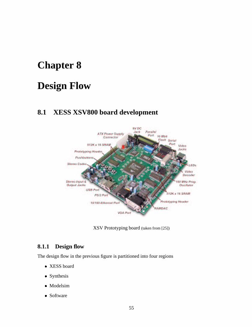
Chapter 8
Design Flow
8.1 XESS XSV800 board development
XSV Prototyping board (taken from [25])
8.1.1 Design flow
The design flow in the previous figure is partitioned into four regions
� XESS board
� Synthesis
� Modelsim
� Software
55
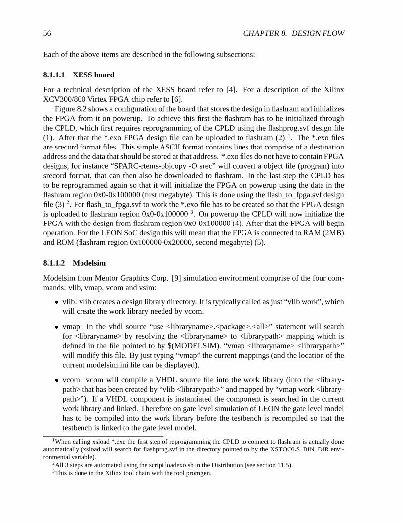
56 CHAPTER 8. DESIGN FLOW
Each of the above items are described in the following subsections:
8.1.1.1 XESS board
For a technical description of the XESS board refer to [4]. For a description of the XilinxXCV300/800 Virtex FPGA chip refer to [6].
Figure 8.2 shows a configuration of the board that stores the design in flashram and initializesthe FPGA from it on powerup. To achieve this first the flashram has to be initialized throughthe CPLD, which first requires reprogramming of the CPLD using the flashprog.svf design file(1). After that the *.exo FPGA design file can be uploaded to flashram (2) 1. The *.exo filesare srecord format files. This simple ASCII format contains lines that comprise of a destinationaddress and the data that should be stored at that address. *.exo files do not have to contain FPGAdesigns, for instance “SPARC-rtems-objcopy -O srec” will convert a object file (program) intosrecord format, that can then also be downloaded to flashram. In the last step the CPLD hasto be reprogrammed again so that it will initialize the FPGA on powerup using the data in theflashram region 0x0-0x100000 (first megabyte). This is done using the flash_to_fpga.svf designfile (3) 2. For flash_to_fpga.svf to work the *.exo file has to be created so that the FPGA designis uploaded to flashram region 0x0-0x100000 3. On powerup the CPLD will now initialize theFPGA with the design from flashram region 0x0-0x100000 (4). After that the FPGA will beginoperation. For the LEON SoC design this will mean that the FPGA is connected to RAM (2MB)and ROM (flashram region 0x100000-0x20000, second megabyte) (5).
8.1.1.2 Modelsim
Modelsim from Mentor Graphics Corp. [9] simulation environment comprise of the four com-mands: vlib, vmap, vcom and vsim:
� vlib: vlib creates a design library directory. It is typically called as just “vlib work”, whichwill create the work library needed by vcom.
� vmap: In the vhdl source “use <libraryname>.<package>.<all>” statement will searchfor <libraryname> by resolving the <libraryname> to <librarypath> mapping which isdefined in the file pointed to by $(MODELSIM). “vmap <libraryname> <librarypath>”will modify this file. By just typing “vmap” the current mappings (and the location of thecurrent modelsim.ini file can be displayed).
� vcom: vcom will compile a VHDL source file into the work library (into the <library-path> that has been created by “vlib <librarypath>” and mapped by “vmap work <library-path>”). If a VHDL component is instantiated the component is searched in the currentwork library and linked. Therefore on gate level simulation of LEON the gate level modelhas to be compiled into the work library before the testbench is recompiled so that thetestbench is linked to the gate level model.
1When calling xsload *.exe the first step of reprogramming the CPLD to connect to flashram is actually doneautomatically (xsload will search for flashprog.svf in the directory pointed to by the XSTOOLS_BIN_DIR envi-ronmental variable).
2All 3 steps are automated using the script loadexo.sh in the Distribution (see section 11.5)3This is done in the Xilinx tool chain with the tool promgen.

8.1. XESS XSV800 BOARD DEVELOPMENT 57
� vsim: when starting vsim from the command line it will start the interactive GUI that iscontrolled either from menus or using tcl commands. “vsim <entityname>” entered intcl will load a design for simulation. See the Mentor Graphics User Manual for a fulldescription of all tcl commands available. A typical session in vsim would be:
– Load a entity: “vsim LEON”
– Show wave window: “view wave”
– Load a saved wave list: “do savefile.do”
– run vsim: “run 10000”
8.1.1.3 Synthesis
Synplify Pro from Synplicity Inc.[12] was used for synthesis. Synplify Pro can either be oper-ated interactively in GUI or in batch mode. Batch mode is called by using the -batch <batchfile>switch. A batch file is created by copying the Snyplify project file, which is itself a tcl script,and appending the “project -run” command line. If multiple configurations should be compiledin one run tcl loop constructs can be used, i.e.:
set freqencies {25.00020.00010.000
}foreach freq $freqencies {
set_option -frequency $freqset_option -top_module "LEON_rom"project -result_file "work/batch_$freq/800hq240_6_rom_$freq.edf"project -run
}
8.1.1.4 Software
The test software requires the gnu cross compilation system leccs to be installed, that can bedownloaded from [8]. A documentation of the gnu gcc, ld, as and the binutil suite can bedownloaded in the rtems documentation section from [2] or by searching the internet. Thecommands and their switches that are used most often are:
� sparc-rtems-gcc:
– -v: output all command issued by gcc
– -T[seg]=[addr]: link segment [seg] to [addr]
– -T[linkscript]: use a custom linkscript. The powerful format of the link script isdescribed in the GNU documentation of the ld command.
� sparc-rtems-objcopy:
– –remove-section=.[sect] : remove unused sections (.i.e. .comment)
– –adjust-vma=[addr] : Reallocate sections to [addr]

58 CHAPTER 8. DESIGN FLOW
– -O [format] : -O srec will output srec format that is used by xsload.
� sparc-rtems-objdump:
– -d: dump disassembly
– -s: output hex dump
– -x: dump all information about all sections
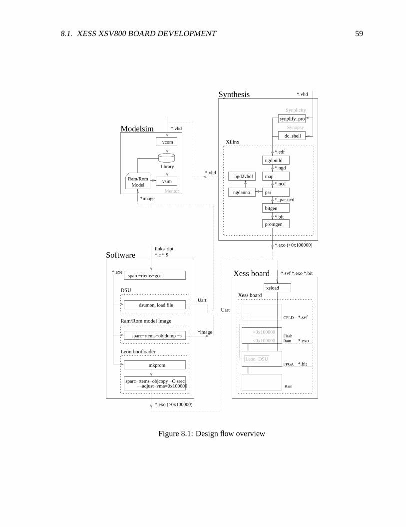
8.1. XESS XSV800 BOARD DEVELOPMENT 59
xsload
Leon−DSU
sparc−rtems−objdump −s
Ram/Rom model image
*.c *.Slinkscript
library
vsimRam/RomModel
ngdanno
ngd2vhdl
dc_shell
synplify_pro
Synplicity
*.bit
*.svf
*.exoRamFlash
FPGA
CPLD
Ram
>0x100000
<0x100000
Xess board
*.svf *.exo *.bit
Uart
*.exe
mkprom
sparc−rtems−objcopy −O srec−−adjust−vma=0x100000
Leon bootloader
sparc−rtems−gcc
Uart
*image
*.exo (>0x100000)
vcom
Mentor
*.vhd
*image *_par.ncd
*.ngd
*.bit
*.ncd
bitgen
promgen
par
map
ngdbuild
Xilinx
*.exo (<0x100000)
*.vhd
*.vhd
*.edf
DSU
dsumon, load file
Software
Modelsim
Synthesis
Xess board
Synopsy
Figure 8.1: Design flow overview

60 CHAPTER 8. DESIGN FLOW
xsload flashprog.svf xsload *.exo xsload flash_to_fpga.svf1 2 3
5
4
(flashram)
parallel
CPLD
FPGA
RAM
ROM
Powerup Running
OperationConfiguration
Figure 8.2: FPGA initialization from flashram
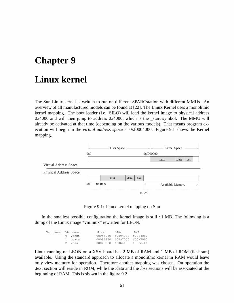
Chapter 9
Linux kernel
The Sun Linux kernel is written to run on different SPARCstation with different MMUs. Anoverview of all manufactured models can be found at [22]. The Linux Kernel uses a monolithickernel mapping. The boot loader (i.e. SILO) will load the kernel image to physical address0x4000 and will then jump to address 0x4000, which is the _start symbol. The MMU willalready be activated at that time (depending on the various models). That means program ex-ecution will begin in the virtual address space at 0xf0004000. Figure 9.1 shows the Kernelmapping.
.text .data .bss
0xf0000000x0
User Space Kernel Space
.text .data .bss
0x40000x0 Available Memory
RAM
Physical Address Space
Virtual Address Space
Figure 9.1: Linux kernel mapping on Sun
In the smallest possible configuration the kernel image is still ~1 MB. The following is adump of the Linux image “vmlinux” rewritten for LEON.
Sections: Idx Name Size VMA LMA0 .text 000a3000 f0004000 f00040001 .data 00017400 f00a7000 f00a70002 .bss 000280f8 f00be400 f00be400
Linux running on LEON on a XSV board has 2 MB of RAM and 1 MB of ROM (flashram)available. Using the standard approach to allocate a monolithic kernel in RAM would leaveonly view memory for operation. Therefore another mapping was chosen. On operation the.text section will reside in ROM, while the .data and the .bss sections will be associated at thebeginning of RAM. This is shown in the figure 9.2.
61

62 CHAPTER 9. LINUX KERNEL
.text .data .bss
.text
0xf0000000x0
User Space Kernel Space
.data .bss
0x4000
0x1000000x0
Available Memory
ROM RAM
0x40000000 0x40200000
Physical Address Space
Virtual Address Space
Figure 9.2: Linux kernel mapping on LEON
9.1 Linux file organization and make system
For a detailed description of the Linux make system read the text file Documentation/knuild/makefiles.txtin Linux source distribution. The LEON Linux port builds on linux-2.4.17. The sources are or-ganized in the following way, that SPARC architecture and LEON dependent directories aremarked bold italic , the directory linux/arch/sparc will be referenced as $(SPARC) in the follow-ing text1:
linux
|->arch
| |->sparc <in the following text this
| |->leon directory will be referenced as $(SPARC)
|->drivers
|->fs
|->include| |->asm
| |->asm-sparc
|->init
|->ipc
|->kernel
|->lib
|->mm
|->net
The main Makefile is located in linux/Makefile with the build rules included from linux/Rules.make.The standard build command are “make xconfig”, “make dep” and “make vmlinux”. “makexconfig” will open a tk configuration screen that is build from $(SPARC)/config.in as the tclsource and $(SPARC)/defconfig as the default configuration2 . “make vmlinux” will compile
1Future distributions should define its own architecture subdirectories, for instance “leon-sparc” instead of“sparc”, this setting was only kept because development was done by modifying the existing source. Introduc-ing a own leon-sparc architecture would require changing the #include statement in all the source files and settingup its own configuration screen config.in files.
2This will create the main configuration file linux/include/linux/autoconf.h included from linux/.config that isthe fist include of every source file
9.1. LINUX FILE ORGANIZATION AND MAKE SYSTEM 63
the kernel. The top makefile linux/Makefile includes $(SPARC)/Makefile where the SPARCsystem dependent parts are configured and custom build rules are defined.
9.1.1 LEON dependent parts
For the LEON port the directory $(SPARC)/leon was added. It includes the makefile, linkerscripts, helper programs, scripts and subdirectories with boot loaders for hardware and for sim-ulation in Modelsim.
9.1.1.1 “make xconfig”
The tcl script $(SPARC)/leon/drivers is included in $(SPARC)/config.in. It adds a LEON cus-tomization window to the tk configuration screen located in the “general setup” configurationentry3. The LEON customization window itself holds input fields to enter XESS Board andLEON synthesis settings. It defines various symbols on exiting, i.e. CONFIG_LEON, CON-FIG_LEON_IU_IMPL ... . Future setting extensions can be allocated in the window. Forinstance different board settings could be made and could be chosen here.
9.1.1.2 “make vmlinux”
The makefile $(SPARC)/leon/Makefile was added. It includes the 2 main rules “hard” and “sim”.“make hard” will create a vmlinux_leon.exo image that can be downloaded to flashram, “makesim” will create sim_vmlinux_text.dump and sim_vmlinux_data.dump that are memory imagesthat are loaded from the Modelsim testbench “atb_linux” defined in mmu/tbench/tbleon_m.vhdof the mmu distribution4 5 . Both “make sim” and “make hard” will first create the imagelinux/vmlinux_leon_nc. This is done in a 2-way process. First the normal “vmlinux” build ruleis activated. This will create linux/vmlinux 6. linux/vmlinux is only needed to determine thesizes of the .text, .data and .bss sections which are needed for the boot loaders and for buildingthe static page table hierarchy. This static page table hierarchy for the boot loader is createdby the helper program $(SPARC)/leon/boot/create_pth that outputs a page table hierarchy insrecord format that will be linked at the end of the .data section of the final linux/vmlinux_leon_ncimage.
3In a future distribution when switching from architecture “sparc” to architecture “leon-sparc” the xconfig screencould be reprogrammed completely. The current version is just a interim solution.
4The testbench will look for tsource/linux/ram.dump and tsource/linux/rom.dump (relative to the di-rectory where vsim was started). The make rule “make sim” will copy sim_vmlinux_text.dump andsim_vmlinux_data.dump to ~/mmu/tsource/linux/rom.dump and ~/mmu/tsource/linux/ram.dump if the directory~/mmu/tsource/linux exist. Therefore you have to add a symlink “mmu” to your home that points to the root of theMMU distribution.
5See section 9.2 for difference between hardware and simulation image.6For the linker instead of the $(SPARC)/vmlinux.lds linker script $(SPARC)/leon/vmlinux.lds is used. The
original linker script $(SPARC)/vmlinux.lds defined more sections than the standard .text, .data and .bss sections.Therefore the LEON linker script $(SPARC)/leon/vmlinux.lds had to combine all sections in .text, .data and .bss.
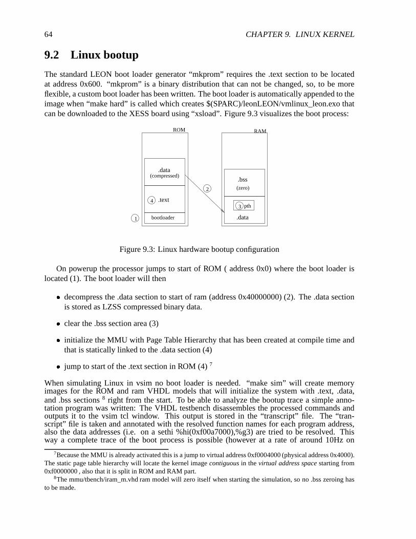
64 CHAPTER 9. LINUX KERNEL
9.2 Linux bootup
The standard LEON boot loader generator “mkprom” requires the .text section to be locatedat address 0x600. “mkprom” is a binary distribution that can not be changed, so, to be moreflexible, a custom boot loader has been written. The boot loader is automatically appended to theimage when “make hard” is called which creates $(SPARC)/leonLEON/vmlinux_leon.exo thatcan be downloaded to the XESS board using “xsload”. Figure 9.3 visualizes the boot process:
1
34
2
bootloader
.text
ROM
.data(compressed)
.data
(zero)
RAM
.bss
pth
Figure 9.3: Linux hardware bootup configuration
On powerup the processor jumps to start of ROM ( address 0x0) where the boot loader islocated (1). The boot loader will then
� decompress the .data section to start of ram (address 0x40000000) (2). The .data sectionis stored as LZSS compressed binary data.
� clear the .bss section area (3)
� initialize the MMU with Page Table Hierarchy that has been created at compile time andthat is statically linked to the .data section (4)
� jump to start of the .text section in ROM (4) 7
When simulating Linux in vsim no boot loader is needed. “make sim” will create memoryimages for the ROM and ram VHDL models that will initialize the system with .text, .data,and .bss sections 8 right from the start. To be able to analyze the bootup trace a simple anno-tation program was written: The VHDL testbench disassembles the processed commands andoutputs it to the vsim tcl window. This output is stored in the “transcript” file. The “tran-script” file is taken and annotated with the resolved function names for each program address,also the data addresses (i.e. on a sethi %hi(0xf00a7000),%g3) are tried to be resolved. Thisway a complete trace of the boot process is possible (however at a rate of around 10Hz on
7Because the MMU is already activated this is a jump to virtual address 0xf0004000 (physical address 0x4000).The static page table hierarchy will locate the kernel image contiguous in the virtual address space starting from0xf0000000 , also that it is split in ROM and RAM part.
8The mmu/tbench/iram_m.vhd ram model will zero itself when starting the simulation, so no .bss zeroing hasto be made.

9.3. MEMORY 65
a 2 GHz PC). This is done with the $(SPARC)/LEON/scripts/annotate.pl script that uses thesim_vmlinux_text.dis and sim_vmlinux_data.dis files to resolve <address> to <symbol> map-pings. sim_vmlinux_text.dis and sim_vmlinux_data.dis are created by “make sim”. All inputand output files for $(SPARC)/LEON/scripts/annotate.pl are configured in $(SPARC)/LEON/scripts/annotate.config.An example of the annotated transcript file is shown below, the left side from “:” is the testbenchoutput, the right side is the part added by $(SPARC)/LEON/scripts/annotate.pl:...#(0xf00b2144:0x400001c7) call 0xf00b2860 : <__init_begin>(<start_kernel>): %rf=0xf00b2144(<__init_begin>)#(0xf00b2148:0x01000000) nop : <__init_begin>()#(0xf00b2860:0x9de3bf90) save %sp,-0x70,%sp : <start_kernel>():%r0x7e=0xf00b1f50()#(0xf00b2864:0x133c029e) sethi %hi(0xf00a7800),%o1: <start_kernel>():%r0x79=0xf00a7800()#(0xf00b2868:0x7ffdbf50) call 0xf00225a8 : <start_kernel>(<printk>):%r0x7f=0xf00b2868(<start_kernel>)#(0xf00b286c:0xd002630c) ld [%o1+0x30c],%o0 : <start_kernel>():%r0x78=0xf00955a0(<__bitops_end>)#(0xf00225a8:0xd223a048) st %o1,[%sp+0x48] : <printk>()#(0xf00225ac:0xd423a04c) st %o2,[%sp+0x4c] : <printk>()#(0xf00225b0:0xd623a050) st %o3,[%sp+0x50] : <printk>()#(0xf00225b4:0xd823a054) st %o4,[%sp+0x54] : <printk>()#(0xf00225b8:0xda23a058) st %o5,[%sp+0x58] : <printk>()#(0xf00225bc:0x81c3e008) retl : <printk>()#(0xf00225c0:0x90102000) mov 0,%o0 : <printk>():%r0x78=0()#(0xf00b2870:0x400003bf) call 0xf00b376c : <start_kernel>(<setup_arch>):%r0x7f=0xf00b2870(<start_kernel>)#(0xf00b2874:0x9007bff4) add %fp,-c,%o0 : <start_kernel>():%r0x78=0xf00b1fb4()#(0xf00b376c:0x9de3bf98) save %sp,-0x68,%sp : <setup_arch>():%r0x6e=0xf00b1ee8()#(0xf00b3770:0x113c0010) sethi %hi(0xf0004000),%o0:<setup_arch>(<__stext>):%r0x68=0xf0004000(<__stext>)#(0xf00b3774:0x133c0304) sethi %hi(0xf00c1000),%o1:<setup_arch>():%r0x69 = 0xf00c1000()#(0xf00b3778:0x90122000) mov %o0,%o0:<setup_arch>():%r0x68=0xf0004000(<__stext>)#(0xf00b377c:0x400023ab) call 0xf00bc628 : <setup_arch>(<skb_init>):%r0x6f=0xf00b377c(<setup_arch>)#(0xf00b3780:0xd0226324) st %o0,[%o1+0x324] : <setup_arch>()...
To avoid long printk() output loops in simulation call “make LEON_SIM=1 sim”, this willdisable printk().
9.3 Memory
It is important to keep in mind that there is only one virtual address space in Linux (even ona combined paging and segmentation architecture like the x86, where multiple virtual addressspaces could be realized, only one virtual address space is provided, see section 2). This virtualaddress space for the kernel is partitioned into different regions at compile time. This parti-tioning differs for every architecture, i.e. on a i386 architecture of Linux the kernel is located atvirtual address 0xc0000000, whereas on SPARC it is located at virtual address 0xf0000000. Thisvalue is defined with the PAGE_OFFSET macro. The underlying physical address space map-ping could be totally arbitrary, however to simplify managing the physical memory resourcephysical address space mapping is coupled as tight as possible to the virtual address space.Therefore on a machine with contiguous memory the kernel image would for instance be lo-cated at the start of physical memory, which would equal a mapping of (vaddr:PAGE_OFFSET-> paddr:0), the free memory that is located after the kernel image would be mapped in thevirtual address space right behind of it so that translation of virtual to physical address andvice versa can be made by simply subtracting or adding the PAGE_OFFSET offset (you haveto keep in mind that the MMU is always enabled when the kernel is running, so that accessto a given physical address can only be made by issuing the corresponding virtual address)9.
9This somehow means that this memory is mapped into kernel space at compile time. At bootup the page tableregion would be initialised on time accordingly.
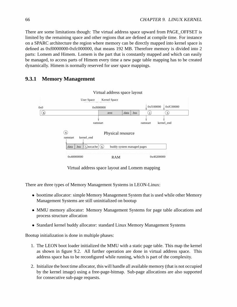
66 CHAPTER 9. LINUX KERNEL
There are some limitations though: The virtual address space upward from PAGE_OFFSET islimited by the remaining space and other regions that are defined at compile time. For instanceon a SPARC architecture the region where memory can be directly mapped into kernel space isdefined as 0xf0000000-0xfc000000, that means 192 MB. Therefore memory is divided into 2parts: Lomem and Himem. Lomem is the part that is constantly mapped and which can easilybe managed, to access parts of Himem every time a new page table mapping has to be createddynamically. Himem is normally reserved for user space mappings.
9.3.1 Memory Management
8. 2. 3.1. .text .data .bss
6.5.
ramstart
.data .bss
0x40000000 0x40200000
buddy system managed pages
kernel_end
RAM
nocache
4. Physical resource
ramstart ramstart kernel_end
0xf0000000x0 0xf100000 0xfC00000
Kernel SpaceUser Space
Virtual address space layout
Virtual address space layout and Lomem mapping
There are three types of Memory Management Systems in LEON-Linux:
� boottime allocator: simple Memory Management System that is used while other MemoryManagement Systems are still uninitialized on bootup
� MMU memory allocator: Memory Management Systems for page table allocations andprocess structure allocation
� Standard kernel buddy allocator: standard Linux Memory Management Systems
Bootup initialization is done in multiple phases:
1. The LEON boot loader initialized the MMU with a static page table. This map the kernelas shown in figure 9.2. All further operation are done in virtual address space. Thisaddress space has to be reconfigured while running, which is part of the complexity.
2. Initialize the boot time allocator, this will handle all available memory (that is not occupiedby the kernel image) using a free-page-bitmap. Sub-page allocations are also supportedfor consecutive sub-page requests.

9.4. PROCESSES 67
3. Initialize the MMU allocator. The MMU allocator will manage a fixed portion of memorythat is allocated using the boot time allocator. This part is marked as (5) in the abovefigure and called NOCACHE.
4. Allocate various other memory portions that should not be managed by the buddy alloca-tor.
5. Allocate the data structures for the buddy allocator using the boot time allocator and ini-tialize them, the buddy allocator is still unused at that point.
6. Allocate page table hierarchy through the MMU allocator and map NOCACHE into vir-tual address space starting from 0xfc000000 (see (3) in the above figure), LEON Lomeminto the virtual address space starting from 0xf1000000 (see (2) in the above figure) andthe kernel starting from virtual address space 0xf0000000 (see (1) in the above figure).
7. Switch to the newly allocated page table hierarchy.
8. Hand over all memory that is left from the boot time allocator to the buddy allocator,including the boot time allocator’s free-page-bitmap as well.
9.4 Processes
9.4.1 Process stack
Figure 9.4 shown the layout of the process stack. The process stack in the SPARC architecturediffers from others in that it has to support window spilling. Remember that the SPARC registerfile is divided into “register windows” (see section 5). Because of the modulo arithmetic ofthe “window counter” on a SAVE or RESTORE command, which decrement or increment thewindow counter, the “current window counter” can run into a already used window. To avoidedthis the “invalid window mask” will mark the wraparound border10, when running into a windowmarked by the “invalid window mask” a “window underflow” or “window overflow” trap isgenerated that will spill out the register window onto the stack. The OS, which handles thewindow spilling, and the program11 share the stack and have to be programmed to work together.This is done in the following way: The compiler will generate programs that will always keepa valid stack pointer in %o6 (%sp) (after a SAVE) respective %i6 (%fp) (before a SAVE)12.The SAVE command that increments the stack pointer is generated so that the first part of thefunction frame is reserved for a possible window spill. Therefore for a given window that shouldbe spilled the OS can use the %sp and %fp registers to determine the stack location.
Figure 9.4 in addition visualizes the kernel stack concept: Each process has a fixed sizememory chunk 13 which contains the task_struct process structure at the beginning. The rest
10This “border” can be multiple windows wide.11To be more precise, the compiler12A function body of a program generated by the sparc-rtems-gcc cross compiler (not written to target Linux)
will reserve at least 104 bytes of spilling memory on the stack by issuing SAVE %sp,-104,%sp. On the other handthe Linux OS will, on a 8 windows SPARC processor with FPU disabled, only spill 64 bytes, sparc-rtems-gcc couldbe optimized here.
13On SPARC this is of size 0x2000 and aligned to 0x2000
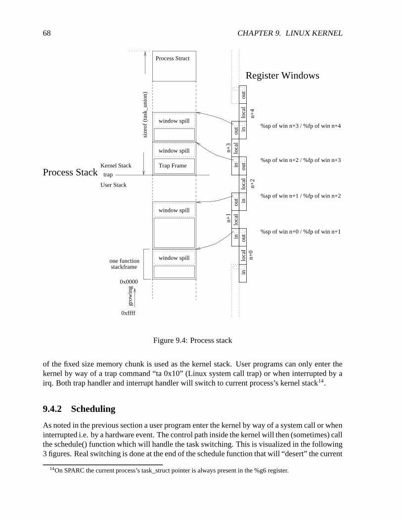
68 CHAPTER 9. LINUX KERNEL
window spill
window spill
window spill
window spill
0xffff
grow
ing
0x0000
loca
lou
tin
loca
lou
tin
loca
lou
tin
inlo
cal
out
inlo
cal
out
n+0
n+1
n+2
n+3
n+4
Trap Frame
Process Struct
stackframeone function
trap
Kernel Stack
User Stack
size
of (
task
_uni
on)
%sp of win n+0 / %fp of win n+1
%sp of win n+1 / %fp of win n+2
%sp of win n+2 / %fp of win n+3
%sp of win n+3 / %fp of win n+4
Process Stack
Register Windows
Figure 9.4: Process stack
of the fixed size memory chunk is used as the kernel stack. User programs can only enter thekernel by way of a trap command “ta 0x10” (Linux system call trap) or when interrupted by airq. Both trap handler and interrupt handler will switch to current process’s kernel stack14.
9.4.2 Scheduling
As noted in the previous section a user program enter the kernel by way of a system call or wheninterrupted i.e. by a hardware event. The control path inside the kernel will then (sometimes) callthe schedule() function which will handle the task switching. This is visualized in the following3 figures. Real switching is done at the end of the schedule function that will “desert” the current
14On SPARC the current process’s task_struct pointer is always present in the %g6 register.

9.4. PROCESSES 69
schedule function’s stack frame and switch into the old schedule function’s stack frame of thetask that should be activated and that had been “deserted” on a previous switch15. The schedule()sequence is visualized in figure 9.5,9.6 and 9.7.
window spill
window spill
window spill
Trap Frame
window spill
window spill
���������
���������
= deserted schedule() frame
window spill
window spill
window spill
ProcessStruct 1
���������������������������������������������
�����������������������������������
���������������������������������������������
�����������������������������������
Trap Frame
window spill
trap
Kernel Stack
User Stack Kernel Thread
window spill
window spill
ProcessStruct 2
ProcessStruct 3
trap
size
of(t
ask_
unio
n)
Proc
ess
1 ru
nnin
g
Figure 9.5: Process 1 running, before call of schedule()
There is a special case when switching processes. The fork() command will create a newtask who’s stack will have to be initialized by hand before letting schedule() jump into it.
Kernel threads (seen in the right row of the above figure) completely run in the kernel stack.They do not have a user stack. On interrupts and traps generated while a kernel thread is runningthe trap frame is placed just on top of the current stack frame. The interrupt and irq handlerhandle this special case.
15On SPARC this is done by swapping %o6 (%sp stack pointer), %o7 return addr, %psr , %wim and then issuinga jmpl %o7+8,%g0 command.

70 CHAPTER 9. LINUX KERNEL
window spillwindow spill
window spill window spill
window spill
Trap Frame
window spill
window spill
window spill
���������
���������
= deserted schedule() frame
window spill
window spill
ProcessStruct 1
window spill
�����������������������������������
�����������������������������������
���������������������������������������������
�����������������������������������
�����������������������������������
�����������������������������������
Trap FrameTrap Frame
window spill
trap
Kernel Stack
User Stack Kernel Thread
window spill
store sp, ret, psr, wim load sp, ret, psr, wim
window spill
ProcessStruct 2
ProcessStruct 3
trap
size
of(t
ask_
unio
n)
schedule( )
Figure 9.6: Schedule()

9.4. PROCESSES 71
window spill
window spill window spill
window spill
Trap Frame
window spill
window spill
window spill
ProcessStruct 1
���������
���������
= deserted schedule() frame
���������������������������������������������
�����������������������������������
������������������������������������������������������
������������������������������������������
Trap Frame
window spill
trap
Kernel Stack
User Stack Kernel Thread
window spill
ProcessStruct 2
ProcessStruct 3
trap
size
of(t
ask_
unio
n)
Proc
ess
2 ru
nnin
g
Figure 9.7: Process 2 running, after call of schedule()

72 CHAPTER 9. LINUX KERNEL

Chapter 10
Appendix A: Components
TLB
1
1
1
1
32
1
32
1
32
1
1
1
1
1
1
1
req_ur
probe_ur
flush_ur
trans_ur
su_ur
read_ur
su_ur
mcmmo
DCache
ICache
ACacheACache
ICache
DCache
MMUprobe_data
nmmctrl2
mcmmi
nmmctrl1
data_ur32
read_ur
trans_ur
data_ur32
cache
accexc1
data
hold_ur1
cache
data
hold_ur
accexc
Figure 10.1: MMU component
73

74 CHAPTER 10. APPENDIX A: COMPONENTS
DCache interface:
dir name desc
in req_ur, trans_ur request translationin probe_ur request probein flush_ur request flushin su_ur, read_ur translation request parameters. su: supervisor = 1in data_ur virtual address or virtual flush/probe address
out hold_ur asserted as long as a operation is still unfinishedout data return physical address on translation operationout probe_data PTE/zero on probe operationout cache address cacheableout accexc asserted on protection, privilege or translation errorin mmctrl1 MMU ctx and ctx pointer control register (from DCache)
out mmctrl2 fault status and fault status register
ICache interface:
dir name desc
in trans_ur request translationin su_ur, read_ur translation request parameters
out hold_ur asserted as long as a operation is still unfinishedout data return physical address on translation operationout cache address cacheableout accexc asserted on protection, privilege or translation error
ACache interface:
(this interface is used by the the Table Walk component)
dir name desc
in mcmmo input from AMBA to the Table Walk component inside TLBout mcmmi output to AMBA from the Table Walk component inside TLB
Table 10.1: MMU component i/o

75
LRU SYNCRAMTW
TLBCAM
TLBCAM
TLBCAM
TLBCAM
1
32
32
1
1
1
1
1
TLBprobe_data
hold_ur1
1cache
1
1
1
1
1
1
n
req_ur
mmctrl1
data_ur
trans_op_ur
probe_op_ur
flush_op_ur
su
read
isid
32
data
fault_inv
fault_pro
fault_pri
fault_trans
fault_mexc
fault_lvl2
dir name desc
in req_ur request operationin trans_op request translationin probe_op request probein flush_op request flushin su 1=supervisorin read 1=read accessin mmctrl1 ctxnr, ctxptr
out hold_ur asserted until operation is finishedout probe_data probe returnout data physical addressout cache address cacheablein isid 1=ICache 0=DCache
out fault_inv invalid page faultout fault_pro protection violationout fault_pri privileged page access violationout fault_trans translation error, page fault (PTE invalid)out fault_mexc memory exception during table walkout fault_lvl page table hierarchy level of fault
Figure 10.0.1: TLB component
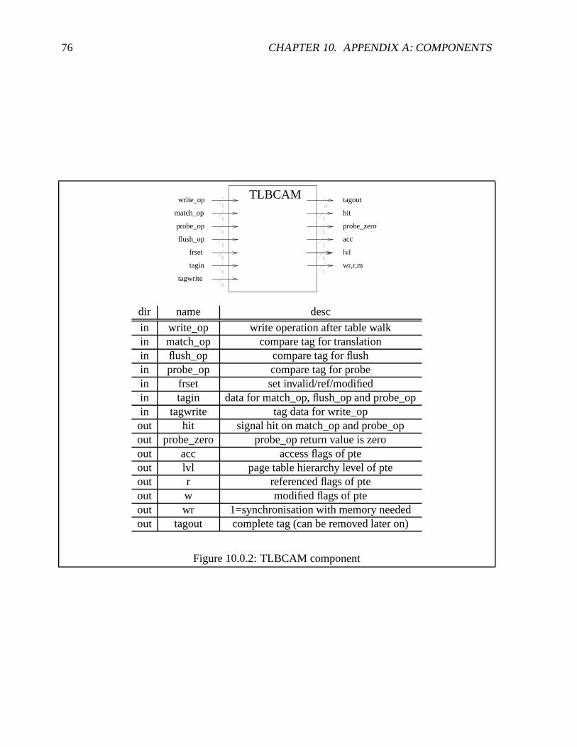
76 CHAPTER 10. APPENDIX A: COMPONENTS
1
1
1
1
1
1
1
1
1
1
match_op
probe_op
flush_op
write_op
frset
TLBCAMn
tagout
hit
lvl
acc
wr,r,m
tagwriten
ntagin
probe_zero
dir name desc
in write_op write operation after table walkin match_op compare tag for translationin flush_op compare tag for flushin probe_op compare tag for probein frset set invalid/ref/modifiedin tagin data for match_op, flush_op and probe_opin tagwrite tag data for write_op
out hit signal hit on match_op and probe_opout probe_zero probe_op return value is zeroout acc access flags of pteout lvl page table hierarchy level of pteout r referenced flags of pteout w modified flags of pteout wr 1=synchronisation with memory neededout tagout complete tag (can be removed later on)
Figure 10.0.2: TLBCAM component

77
1
32
32
32
1
32
32
1
1
1
probe_op_ur
writeback_op_ur
probe_typen
hold
data
2lvl
TWwalk_op_ur
adata
aready
agrant
32aread
32areq
32
32aaddr
adata
mcmmimcmmo
fault_trans
fault_mexc1
fault_lvl2
addr
32data
Figure 10.0.3: TW component
dir name desc
in walk_op_ur table walk operationin probe_op_ur probe operation
in probe_type Type of probe (see [21])
in data virtual address/probe address
out data pte
out faulttrans page fault
out faultmexc AMBA error
in aaddr, adata, areq, aread AMBA interface for TLB
out aready, agrant, adata AMBA interface for TLB
Figure 10.0.4: TW component

78 CHAPTER 10. APPENDIX A: COMPONENTS
1
LRUE
LRUE
LRUE
LRUE
touch
posn
1touchmin
LRU posn
nmmctrl1
dir name desc
in touch same as LRUEin pos same as LRUE
out pos Outputs the tail entry addressin touchmin tail element should “bubble to front”
Figure 10.0.5: LRU component
1 1touch
posn
1clear
n
1
right
fromright
movetopLRUEpos
n
nleft
fromleft1
dir name desc
in touch force compare of entry addr (set “bubble to front” mark)in pos entry addr to compare toin clear 1=topmost element (“bubble to front” stop)in fromleft interconnecting elements
fromright interconnecting elementsin left, right signal copyin movetop signal “bubble to front” one pos
out pos output entry addr
Figure 10.0.6: LRUE component, single entry in LRU component

Chapter 11
Appendix B: MMU distribution
11.1 Distribution overview
LEON2-1.0.5|->mmu. |->modelsim. |->scripts
|->syn|->tsource|->tbench|->vhdl|->xess
The MMU is build on top of LEON distribution version LEON2-1.0.5. To install mmu.tar.gzdistribution you have to first install the LEON2-1.0.5.tar.gz. After that unzip and tar mmu.tar.gzinto the LEON2-1.0.5 directory. When working with Modelsim the working directory has tobe set to LEON2-1.0.5/mmu so that the original files can be accessed in ../. The subdirectoriesLEON2-1.0.5/mmu/scripts and LEON2-1.0.5/mmu/xess are aimed on hardware developmenttargeted for a XESS Corporation XSV800 board with the following software installed:
� Synthesis: Synplify Pro, Synplicity Inc. [12].
� Xilinx: Xilinx ISE 4.1 [6].
� XESS: “xsload” tool, a Linux port can be found at [1, 25].
� Cross compilation suite leccs for building the test software [8].
11.2 Subdirectory mmu/modelsim/
This directory contains the Modelsim compile.do script that will compile the processor modelin the correct order. Modelsim has to be started from the mmu/ directory as root for this to work.
79
80 CHAPTER 11. APPENDIX B: MMU DISTRIBUTION
Alternatively the “make vsim” executed in the mmu/ directory that uses Makefile build systemcan be used.
11.3 Subdirectory mmu/syn/
This directory and the other projects subdirectory contains various Synplify_pro projects. Thedifferent projects differ only in the target frequency and the technology settings (XCV800 orXCV300), the use the same VHDL files. The design is not tested for other synthesis tools likeSynopsis design compiler. The top entity is mmu/xess/vhdl/leon_rom.vhd that targets the XSVBoard with flashram accessed as ROM.
11.4 Subdirectory mmu/tbench/
11.4.1 Testbenches for MMU components mmu/tbench/comp
The MMU test suite require two files: a memory image and a virtual address vector file. Thememory image is created using the “image” tool (see section 11.6.1). The address vector file iscreated using the “image” tool in analyze mode (-a) and option -v to extract the address vectorsfrom the created image.
11.4.1.1 TLB_cam.vhd
The TLBCAM testbench test the function of the TLBCAM component. It uses simple testvectors written directly into TLB_cam.vhd.
11.4.1.2 tw_tb.vhd
The TW testbench test a Table Walk. The virtual addresses of the virtual address file are enteredone after another.
11.4.1.3 TLB_tb.vhd
The TLB testbench test a sequence of virtual address translations. The virtual addresses of thevirtual address file are entered one after another.
11.4.1.4 mmu_tb.vhd
The MMU testbench simulates the concurrent translation requests from DCache and ICache. Itneeds three input files: a memory image, a virtual address vector file and a command file. TheDCache and ICache request sequence can be specified in command file mmu_cmd.txt file. It hasthe following format: Each line is one command. Starting from the first command every secondcommand is a DCache command, starting from the second command each second command is aICache command. DCache commands take the format: [read|write|flush|probe] [addrnr] [flags],ICache command take the format [read] [addrnr] [flags]. On a DCache or ICache read or write

11.5. SUBDIRECTORY MMU/SCRIPTS/ (XESS BOARD DEVELOPMENT) 81
command [flags] can be “su” (supervisor) or “u” (user), on a DCache flush or probe command[flags] can be “page”, “segment”, “region” , “context” or “entire”. [addrnr] is the index into thevirtual address file’s array of addresses. See mmu/tbench/comp/mmu_cmd.txt for an example.
11.5 Subdirectory mmu/scripts/ (XESS board development)
The subdirectory mmu/scripts include scripts to ease hardware development targeting a XSVboard. The scripts automate the tool chain handling and the XSV board configuration. To usethese scripts add this directory to your PATH environmental variable.
11.5.1 syn.pl: Xilinx tool chain build scripts
syn.pl covers part of the Synthesis domain in design flow in figure 8.1 which simplifies workingwith the Xilinx tool chain. It uses the configuration file mmu/scripts/syn.config to determine thedirectories where to search for *.ucf and *.edf files. (Adjust syn.config to your environment).Various ucf files for xess board are provided in the subdirectory mmu/xess/ucf. syn.pl lets youinteractively
� choose target technology, for XSV800 or XSV300
� choose ucf-file
� choose *.edf file
� choose commands
� save/load batch file.
An example of a saved batch file of syn.pl would be:
#!/bin/sh UCFDIR=/home/eiselekd/mmu/scripts/../xess/ucf
WORKDIR=/home/eiselekd/mmu/scripts/../syn/work/batch_25.000
ENTITY=800hq240_6_rom_25 UCF=xsv_romdsu_25hz.ucf
TECH=XCV800HQ240-6
cd $WORKDIR
ngdbuild -a -p XCV800HQ240-6 -uc ${UCFDIR}/${UCF} 800hq240_6_rom_25
map -u 800hq240_6_rom_25
echo "!!!!!Maybe you should change the overall efford level using -l switch 0-5!!!:"
par -w 800hq240_6_rom_25 800hq240_6_rom_25_par
bitgen -w 800hq240_6_rom_25_par 800hq240_6_rom_25
promgen -p exo -o 800hq240_6_rom_25_exo.exo -x 1M -c 0xFF -w -u 0 800hq240_6_rom_25.bit

82 CHAPTER 11. APPENDIX B: MMU DISTRIBUTION
11.5.2 selexo.sh : Handling the board
selexo.sh covers the XESS domain in figure 8.1 . To simplify configuration of the XESS boardthe interactive script selexo.sh is provided in the mmu/scripts directory. selexo.sh uses the con-figuration file mmu/scripts/selexo.config will determine directories where to search for *.exofiles. (Adjust selexo.config to your environment). The main screen looks like this:
eiselekd@ralab18:~/mmu/scripts$ selexo.sh
1) Reprogram clock
2) Stop Processor
3) Download exo
4) Exit#?
selexo.sh handles 3 common task:
� Reprogramming the clock: this will use the CPLD design oscxsv.svf provided in themmu/xess/svf directory.
� Stopping the processor: When reprogramming the flashram the processor running on theFPGA has to be flushed first (because it still accesses flashram). Stopping the processoris done by reprogramming the CPLD with downpar.svf provided in the mmu/xess/svfdirectory, after that when repowering the board the FPGA remains empty.
� Downloading *.exo files: this will show a screen where up to two *exo files for downloadcan be selected. The previous selection is kept persistent. This section in turn uses theloadexo.sh script provided in mmu/scripts directory. An example screen would look likethis:
[ 1]: /home/eiselekd/archive/10hz20hz25hz/hello-LEON-25hz-38400baud.exo (Sat Aug 31 18:39:16 2002)[ 2]: /home/eiselekd/archive/10hz20hz25hz/hello-LEON-10hz-19200baud.exo (Sat Aug 31 18:39:39 2002)[ 3]: /home/eiselekd/archive/10hz20hz25hz/hello-LEON-10hz-38400baud.exo (Sat Aug 31 18:39:54 2002)[ 4]: /home/eiselekd/exosoftarchive/10hz20hz25hz/hello-LEON-25hz-19200baud.exo (Sat Aug 31 18:39:30 2002)[<sel> 5]: /home/eiselekd/work/batch_20.000/800hq240_6_rom_20_exo.exo (Tue Sep 3 22:02:36 2002)[ 6]: /home/eiselekd/work/batch_25.000/800hq240_6_rom_25_exo.exo (Fri Sep 6 09:32:06 2002)[ 7]: /home/eiselekd/work/300batch_25.000/300PQ240_4_rom_25_exo.exo (Tue Sep 3 18:27:55 2002)[x]: Execute[q]: Quit
11.6 Subdirectory mmu/tsource
When running LEON on a XSV300/800 board with the top entity mmu/xess/vhdl/leon_rom.vhd(the flashram appears as ROM 0x00000000 in the LEON address space) several possibilities canbe used to run a program (this is shown in the “Software” part in figure 8.1) :
� using xsload to program the flash with a program that has been linked to address 0x00000000,this way only read-only .data section can be used (no global variables used).
� using mkprom to create a boot loader that extracts a ELF program to the specified location.Only .text, .data, and .bss segments are supported, therefore a custom build script has to
11.6. SUBDIRECTORY MMU/TSOURCE 83
be used to make sure a all sections are placed in one of the three segments. Default linkaddress for .text should be 0x40000000, when using 0x600 (i.e. using switch -qprom or-Ttext=0x600) the .text segment will remain in flashram while only the .data and .bss willbe allocated in ram by the boot loader.
� using “load” command of “dsumon”, the design has to be be synthesized with the debugsupport monitor activated. The “load” command of “dumon” loads the ELF program intomemory
11.6.1 image: Creating page table hierarchies
To be able to test the MMU functionality a static memory image containing a initialized pagetable hierarchy has to be created. This is done with the “image” tool, which takes a configurationfile and creates a memory image from it. Its sources are located in mmu/tsource/imagecreate.When running “make” in mmu/tsource/imagecreate the image executable will be copied intommu/scripts. Use image with options:
image [-a] [-v] [-m] [-c <config>] [<outfile>]-m: modify (read in outfile first)-a: analyse mode-c <file>: configuration file-v: print out virtual addresses-o: Offset image base address (0x0 default)The default configuration file is config.txtThe default outfile is mem.dat
Image will output 3 files, mem.dat for initializing mmu/tbench/comp/mmram.vhd, mem.dat.imagefor initializing with mmu/tbench/iram.vhd and mem.dat.dsu, which is a srecord file and can beused to directly link to a executable (.data section). This way, in combination with dsumon’s(hardware debug support unit monitor) load command, a memory image containing preinitial-ized page table hierarchy can be directly loaded into the XESS boards memory. (Note: linkscript parameters and -o offset has to match). The format of the configuration file is composedof one command each line. Comments are trailed by #.
� allocate context level page (4GB) of context [ctxnr] with vaddr(—,—,—) at physical addr[addr] :c [ctxnr] [addr] [flags]
� allocate region level page (16 MB) of context [ctxnr] with vaddr(index1,—,—) at physicaladdr [addr]:g [ctxnr] [index1] [addr] [flags]
� allocate segment level page (256k) of context [ctxnr] with vaddr(index1,index2,—) atphysical addr [addr]:m [ctxnr] [index1] [index2] [addr] [flags]
� copy [file] into memory and map it starting from virtual address ([index1] [index2] [in-dex3]) of context [ctxnr]:p [ctxnr] [index1] [index2] [index3] [file] [flags]

84 CHAPTER 11. APPENDIX B: MMU DISTRIBUTION
� fill whole region ([index1] ,—, —) of context [ctxnr] with segments starting at physicaladdr [addr] :M [ctxnr] [index1] [addr] [flags]
� fill whole context [ctxnr] with regions starting at physical addr [addr] :G [ctxnr] [addr] [flags]
� remove a pte entry at level [level] of along the path of virtual address ([index1] [index2][index3]) of context [ctxnr]:- [ctxnr] [index1] [index2] [index3] [level]
Values allowed for [flags] are: CACHE, DIRTY, REF, EXEC, WRITE, VALID, PRIV andPRIV_RDONLY. An example of a configuration file is given below, It would map the wholevirtual address space of context 0 one-to-one to the physical address space using region page ta-ble entries, where at 0x40000000 segment page table entries are used to cover the whole addressspace.
G 0 0 EXEC- 0 64 0 0 1M 0 64 40000000 EXEC
A example output of a image run is given below:
eiselekd@ralab10:$./imageinit task [-1][line 6] : allocate pmd for [0](0)(0)(--) [:0000000000:]init task [0]add PGD tbl to CTX: [pgdia:0040009000:] at [ctxia:0040009400:]add PMD tbl to PGD: [pmdia:0040009800:] at [pgdia:0040009400:]add *pte* to PMD tbl: [ia:0040009800:] pageia:0040000000 <size:0000040000>flags[c:- d:- r:- e:x w:- v:- p:- pr:-]setflags from[0004000002] to [000400000a](ored:0000000008[line 8] : allocate file testprogs/p1.o taskid[1] [0][0][0]initLoading testprogs/p1.o (rs:356,aligned:356)Copy file content to ia:004000b000, converting with htonl()add PGD tbl to CTX: [pgdia:0040009004:] at [ctxia:004000c000:]add PMD tbl to PGD: [pmdia:0040009900:] at [pgdia:004000c000:]add PTE tbl to PMD: [pteia:0040009a00:] at [pmdia:0040009900:]flags[c:- d:- r:- e:x w:- v:- p:- pr:-]setflags from[0004000b02] to [0004000b0a](ored:0000000008add 4k *pte* to PTE table: [pageia:004000b000:] at [pteia:0040009a00:]= vaddr (1) (0)(0)(0)[line 9] : allocate file testprogs/p2.o taskid[1] [0][0][1]Loading testprogs/p2.o (rs:80,aligned:80)Copy file content to ia:004000d000, converting with htonl()flags[c:- d:- r:- e:x w:- v:- p:- pr:-]setflags from[0004000d02] to [0004000d0a](ored:0000000008add 4k *pte* to PTE table: [pageia:004000d000:] at [pteia:0040009a04:]= vaddr (1) (0)(0)(1)Output:mem.datOutput:mem.dat.imageOutput:mem.dat.dsu
11.6.1.0.1 Analysing page table hierarchies To analyse the page table hierarchy of a mem-ory image the image program can be called with the -a option. This will output the page tablehierarchy.
eiselekd@ralab10:$ ./image -a####################### Analyzing mem.dat*ctxp: 0040009000*CXT[00000]: [:0040009400:]|->PGD[00000]: [:0040009800:] |c|d|r|e|w|v|p|pr|| |->PMD[00000]: *pte*[:0040000000-0040040000:] (000)(000)(000)(---)| |-|-|-|x|-|x|-|-| pte: 0x000400000aCXT[00001]: [:004000c000:]|->PGD[00000]: [:0040009900:]

11.6. SUBDIRECTORY MMU/TSOURCE 85
| |->PMD[00000]: [:0040009a00:] |c|d|r|e|w|v|p|pr|| || |->PTE[00000]: *pte*[:004000b000-004000c000:] (001)(000)(000)(000)| | |-|-|-|x|-|x|-|-| pte: 0x0004000b0a| |->PTE[00001]: *pte*[:004000d000-004000e000:] (001)(000)(000)(001)| |-|-|-|x|-|x|-|-| pte: 0x0004000d0aeiselekd@ralab10:$
11.6.1.0.2 Dumping memory content of testbench The mmu/tbench/iram.vhd memory mod-els of the testbench was extended so that memory dumps could be forced. A memory dump isinitiated when by the following sequence:
unsigned int *ioarea = (unsigned int *) 0x20000000;ioarea[100] = 0;ioarea[100] = 1;
This will cause a rising edge in the dump signal of iram. The memory content will be be writtenin the same directory as the initialization file of iram that is specified in the tbench configuration.Because the memory is composed of several iram components the memory content will be splitinto several files. To merge them the imagemerge.pl script is provided in the mmu/tsource/scriptsdirectory. It takes the initialization filename as an argument. (Note: first call “make” in thisdirectory , because imagemerge.pl script will need imagemerge.exe program to be compiled ).An example is shown here:
eiselekd@ralab10:$ ls testos_ram.dat* -la-rw-r--r-- 1 eiselekd SDA 45221 Aug 25 14:35 testos_ram.dat-rw-r--r-- 1 eiselekd SDA 1507360 Aug 25 14:38 testos_ram.dat.b0.ar0.dump-rw-r--r-- 1 eiselekd SDA 1507360 Aug 25 14:38 testos_ram.dat.b0.ar1.dump-rw-r--r-- 1 eiselekd SDA 1507360 Aug 25 14:38 testos_ram.dat.b1.ar0.dump-rw-r--r-- 1 eiselekd SDA 1507360 Aug 25 14:38 testos_ram.dat.b1.ar1.dumpeiselekd@ralab10:$ ./imagemerge.pltestos_ram.dat Using base: testos_ram.dat./testos_ram.dat.b0.ar0.dump: Bank 0, arr 0./testos_ram.dat.b0.ar1.dump: Bank 0, arr 1./testos_ram.dat.b1.ar0.dump: Bank 1, arr 0./testos_ram.dat.b1.ar1.dump: Bank 1, arr 1./imagemerge.exe testos_ram.dat.merge ./testos_ram.dat.b0.ar0.dump ./testos_ram.dat.b0.ar1.dump ./testos_ram.dat.b1.ar0.dump ./testos_ram.dat.b1.ar1.dumpoutput:Tying to open file ./testos_ram.dat.b0.ar0.dumpContent: index:0 bank:0 Abits:19 Echk:4 Read 1507328 bytesTying to open file ./testos_ram.dat.b0.ar1.dumpContent: index:1 bank:0 Abits:19 Echk:4 Read 1507328 bytesTying to open file ./testos_ram.dat.b1.ar0.dumpContent: index:0 bank:1 Abits:19 Echk:4 Read 1507328 bytesTying to open file ./testos_ram.dat.b1.ar1.dumpContent: index:1 bank:1 Abits:19 Echk:4 Read 1507328 bytesTying to open output file testos_ram.dat.merge
11.6.2 Small Operating System (SOS)
SOS is a set of routines for testing of the MMU. They are also used by the image tool to createstatic page table hierarchies.
86 CHAPTER 11. APPENDIX B: MMU DISTRIBUTION
11.7 Subdirectory mmu/vhdl/
This directory contains the sources for the MMU and the changed LEON design files. The newlyadded files for the MMU are mmu.vh, mmu_config.vhd, TLB_cam.TLB, TLB.vhd, tw.vhd,lru.vhd and lrue.vhd. These files are described in chapter 10. The LEON design files thathave been changed are marked with a postfix “_m”. These are: acache_m.vhd, ICache_m.vhd,DCache_m.vhd, cache.vhd, cachemem.vhd, iu.vhd, iface.vhd and sparcv8.vhd.
11.8 Subdirectory mmu/xess/ (XESS board development)
This directory includes the files needed when targeting XESS XSV800 and XSV300 boards. Themmu/xess/svf subdirectory include CPLD designs that are used for reprogramming the CPLD sothat flashram can be accessed and that the UART signals are routed out. The mmu/xess/vhdl con-tain the top level entity for a LEON design running on a XSV board that accesses flashram. Thesubdirectory mmu/xess/ucf include the .ucf constraint files used for the Xilinx tool ngdbuild. The.ucf file define the pin mapping used for a design. For instance when using the top level entitymmu/xess/vhdl/leon_rom.vhd running on 25MHz the constraint file mmu/xess/ucf/xsv_rom_25hz.ucfshould be used.

Chapter 12
Appendix C: MMU source
12.1 Source code
The source code of the MMU components is appended after page 88.
87

88 CHAPTER 12. APPENDIX C: MMU SOURCE

Bibliography
[1] Daniel Bretz, Digitales Diktiergerät als System-on-a-Chip mit FPGA-Evaluierungsboard,Master’s thesis, Institute of Computer Science, University of Stuttgart, Germany, February2001.
[2] OAR Corp, RTEMS Documentation, http://www.oarcorp.com/rtems/releases/4.5.0/rtemsdoc-4.5.0/share/index.html, 2002.
[3] OAR Corporation, RTEMS Web Site, http://www.oarcorp.com, 2002.
[4] XESS Corporation, XSV Board Manual, http://www.xess.com, 2001.
[5] Marco Cesati Daniel P. Bovert, Understanding the linux kernel, O’Reilly, 2001.
[6] Virtex Datasheet, DS003-2 (v2.6) Virtex 2.5V, Field Programmable Gate Arrays , http://www.xilinx.com/, July 2001.
[7] Source distribution, MMU for Leon, http://www.tamaki.de/data, 2002.
[8] Jiri Gaisler, LEON Web Site, http://www.gaisler.com/, 2002.
[9] Mentor Graphics homepage, Mentor Graphics, http://www.mentor.com, 2002.
[10] Free Software Foundation Inc., GNU, http://www.gnu.org, 2002.
[11] RedHat Inc., eCos, http://www.redhat.com, 2002.
[12] Synplicity Inc., Synplicity, http://www.synplicity.com/, 2002.
[13] Sun Microsystems, Sun Microsystems, Inc., http://www.sun.com, 1999.
[14] Milan Milenkovic, Microprocessor memory management units, IEEE Micro, 10(2):p70-85(1990).
[15] MIPS., MIPS R�
Technologies, Inc., http://www.mips.com, 2002.
[16] E.I. Organick, The Multics Multics, 1972.
[17] Embedded Linux/Microcontroller Project, cULinux, http://www.uclinux.org,2002.
[18] Gaisler Research, The LEON-2 User’s Manual, http://www.gaisler.com/, 2002.
89

90 BIBLIOGRAPHY
[19] Michael I. Slater, Risc Multiprocessors, 1992.
[20] Inc. SPARC R�
International, SPARC International Web Site, http://www.sparc.com, 2002.
[21] Inc. SPARC International, SPARC Architecture Manual Version 8, http://www.sparc.org, 1992.
[22] sun hardware faq, SUN SPARC models, http://www.sunhelp.org/faq/sunref1.html,http://www.sunhelp.org/faq, 2002.
[23] Albert S. Tannenbaum, Andrew S.: Woodhull, Operating Systems, Design and Implemen-tation. Second Edition., 1997.
[24] LEOX Team, LEOX, http://www.leox.org, 2002.
[25] XESS Corperation web site, XESS Web Site, http://www.xess.com, 2002.

Ich versichere hiermit, dass ich diese Arbeit selbständig verfasst und nur die angegebenenHilfsmittel verwendet habe.
Konrad Eisele