unleashing the power of autodesk® fusion 360™ in...
TRANSCRIPT

Unleashing the Power of Autodesk® Fusion 360™ in Product Design Alex Lobos – Rochester Institute of Technology, Professor of Industrial Design – Primary Speaker Keqing Song – Autodesk, Product Manager – Co-Speaker MA1530 This class demonstrates the use of Autodesk Fusion 360 software as a service throughout various stages of product design, while taking advantage of the software’s intuitive approach and versatile modeling modes. The class combines quick demos and project examples in areas such as consumer products, sports equipment, and packaging. Attendees discover how Fusion 360 makes it easy to turn early concepts into final designs as part of the Autodesk® Product Design Suite. The class also highlights the exciting opportunities that Fusion 360 provides for cloud-based collaboration, thanks to the Autodesk® 360 cloud services hub.
Learning Objectives At the end of this class, you will be able to: • Use Fusion 360 to design for product categories such as electronics, consumer products, packaging, and sports
equipment. • Explain how Fusion 360 accelerates form exploration, early concept development, and final design definition. • Generate ideas for integrating Fusion 360 with other programs in the Autodesk Product Design Suite. • Take advantage of cloud-based collaboration by using products in the Autodesk 360 environment.
About the Speakers Alex Lobos is an assistant professor of industrial design and extended program faculty at Golisano Institute for Sustainability at Rochester Institute of Technology. He is also a member of Autodesk’s Expert Elite Program. For more information on Alex Lobos’ research, students’ work and professional portfolio, go to: http://lobosdesign.wordpress.com/ Keqing Song is a Fusion 360 Product Manager focused on customer experience and loyalty, also a creative innovator, coffee addict, whisky enthusiast, photo geek, car guy and watch nerd.
What is Fusion360 and what makes it different? Fusion 360 is a 3D CAD software that integrates mechanical and product design into one workflow. By providing both surface and solid modeling in a single environment, it is possible to create designs with a wide variety of modeling styles and levels of definition from initial concept to finalized design. Some of Fusion 360’s key features and benefits include:

Unleashing the Power of Autodesk® Fusion 360™ in Product Design
2
Intuitive interface and workflow Fusion 360’s design is simple, clean and organized. This allows users to focus on modeling rather than on looking at a cluttered interface or wasting time looking for features. Solids and surfaces in a single place You can choose from two modeling options: Sculpt (surfaces) and Model (solids). This allows for different types of modeling styles to co-exist in a single space and for objects to be converted from one type of geometry to the other. Modeling in real time Traditional CAD is based on creating sketches that then can be turned into objects. Fusion 360 allows you to by-pass sketches and to edit geometry directly, providing a feeling of modeling in real time. This is crucial for Product Design as it allows for a more direct and smooth form exploration. Ability to define design intent While Fusion 360 offers a streamlined workflow it is still loaded with high performance features and settings. Any model can easily progress from initial concept to precise design, as needed for manufacturing and fabrication. This smooth process provides more opportunities for integration of form, function and beyond. Collaboration and cloud-based opportunities Fusion 360 runs natively in both OSX and Windows and it is cloud based. This means that remote collaboration is easy and effective. Fusion’s dashboard allows to share models and additional data (files, videos, pictures) among different users. It also offers plug-ins for simulation, rendering and other tools, either as part of Autodesk 360 suite or as third-party applications.
Using Fusion360 in Product Design The following examples will demonstrate a variety of different modeling techniques that highlight Fusion 360’s simple workflow. The examples have been designed to highlight creating of various forms (organic, geometric, etc.) and modeling styles (solid and surface based). They also highlight different product categories, reflecting the diverse industries covered in product design. Each example also has a link to a video that demonstrates the modeling process.
• Example 1: Wristwatch – Page 3 • Example 2: Desktop lamp – Page 12 • Example 3: Glass bottle – Page 20 • Example 4: Mesh experience – Page 28

Unleashing the Power of Autodesk® Fusion 360™ in Product Design
3
Example 1: Wristwatch Video link: http://youtu.be/d1lD5KvbJqw Key highlights:
• Modeling surfaces in Sculpt mode • Build designs with primitive shapes (Quadball) • Adding geometry via Edit-Form • Editing geometry in real time • Converting surfaces to solids
A. CREATE WATCH’S CASE
1. Set workspace to “Sculpt” mode. 2. Create a Quadball with the following settings:
a. Radius: 50mm b. Span faces: 2 c. Symmetry: Mirror at X and Y planes d. Operation: New body
3. Go to Modify>Edit Form: a. Set Selection Filter to “body.” b. Select body and use vertical scale handle to flatten shape (Fig. W01). c. Change Selection Filter to “face”, select top faces and further flatten shape.
Fig. W01
B. CREATE WATCH’S BRACELET
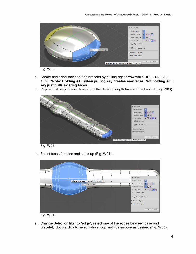
4. Go to Modify>Edit Form: a. Set Selection Filter to “face” and select right 4 faces (Fig. W02).
Unleashing the Power of Autodesk® Fusion 360™ in Product Design
4
Fig. W02
b. Create additional faces for the bracelet by pulling right arrow while HOLDING ALT KEY. **Note: Holding ALT when pulling key creates new faces. Not holding ALT key just pulls existing faces.
c. Repeat last step several times until the desired length has been achieved (Fig. W03).
Fig. W03
d. Select faces for case and scale up (Fig. W04).
Fig. W04
e. Change Selection filter to “edge”, select one of the edges between case and bracelet, double click to select whole loop and scale/move as desired (Fig. W05).

Unleashing the Power of Autodesk® Fusion 360™ in Product Design
5
Fig. W05
f. Change Selection filter to “faces”, select faces for case and scale/move up to refine position of case/bracelet (Fig. W06).
Fig. W06
C. CREATE BEZEL AND DOME
5. Go to Modify>Edit Form: a. Set Selection Filter to “face” and select top 4 faces of case.
6. Create bezel edge by scaling up the faces while HOLDING ALT KEY. Then move down and scale as desired (Fig. W07).
Fig. W07

Unleashing the Power of Autodesk® Fusion 360™ in Product Design
6
7. Change Selection filter to “vertex”, select top center point in the case and move up to create crystal dome (Fig. W08).
Fig. W08
D. CONVERT TO SOLID
8. Go to Modify>Convert. Select watch body and click OK to convert it into a solid.
E. ADD HOLES TO BRACELET
9. Change workspace to “Model” mode. 10. Go to Modify>Move and make a window with the mouse that covers the entire watch body,
then move it up about 30mm (Fig. W09). **Note: Moving the body up will allow you to draw a sketch on the top plane and select it without having the watch in the way.
Fig. W09

Unleashing the Power of Autodesk® Fusion 360™ in Product Design
7
11. Go to Sketch>Create Sketch: a. Select the top plane. b. Under sketch, select “ellipse” and draw an ellipse near the end of the rear bracelet
(Fig. W10).
Fig. W10
12. Go to Modify>Press Pull, select ellipse face and pull up to CUT through the bracelet. 13. Go to Modify>Fillet, select top and bottom edge of hole and set fillet to 5mm (Fig. W11).
Fig. W11
14. Go to Create>Pattern>Rectangular Pattern: a. For objects, select hole, top and bottom fillets. b. For direction, select axis parallel to watch’s length. c. Set distance to 350mm. d. Set quantity to 12. e. Uncheck to iterations that sit on case and last iteration (Fig. W12).
Fig. W12

Unleashing the Power of Autodesk® Fusion 360™ in Product Design
8
F. CREATE BRACELET TAB
15. Go to Construct>Offset Plane: a. Select top plane and offset a plane about 50mm up from it.
16. Go to Sketch>Create Sketch: a. Select the offset plane. b. Under sketch, select “ellipse” and draw an ellipse near the end of the front bracelet
(Fig. W13).
Fig. W13
17. Go to Sketch>Create Sketch: a. Select the top plane of the tab. b. Go to Sketch>Offset, select the edge of the tab and set offset to 2mm.
18. Go to Modify>Press Pull, select the tab’s top face and offset and pull up to JOIN the bracelet (Fig. W14).
Fig. W14

Unleashing the Power of Autodesk® Fusion 360™ in Product Design
9
19. Go to Modify>Press Pull, select the bottom face of the tab and pull it up so that it ends inside the bracelet (Fig. W15).
Fig. W15
20. Go to Modify>Fillet and add a 1mm fillet to the edges of the tab. Congratulations! You have completed the wristwatch example.

Unleashing the Power of Autodesk® Fusion 360™ in Product Design
10
Example 2: Desktop Lamp Video link: http://youtu.be/THOOCz1NajA Key highlights:
• Modeling with solids in Model mode • Creating and editing geometry with as
few sketches as possible • Different ways of editing geometry
(Press-Pull vs. Move vs. Extrude) • Creating new objects (Join vs. New Body
vs. New Component) • Assigning materials and rendering
A. CREATE LAMP’S BASE
1. Set workspace to “Model” mode. 2. Go to Create>Cylinder:
a. Select top plane b. Set diameter to 200mm and height to 50mm
3. Go to Modify>Move: a. Select cylinder’s top face b. Turn X-angle slide to 15deg (Fig.L01).
Fig. L01
4. Go to Modify>Fillet, select top edge of cylinder and add a fillet of 15mm (Fig.L02).
Fig. L02

Unleashing the Power of Autodesk® Fusion 360™ in Product Design
11
B. CREATE LAMP’S ARM 5. Go to Create>Box:
a. Select top face of base as sketch plane. b. Draw a box of the center of the face with Length 20mm and Width 60mm, and press
Enter (Fig. L03).
Fig. L03
c. Continue defining the sketch by pulling arrows so that you end up with a box Length 40mm, Width 120mm, Height 300mm (Fig.L04). **Note: doing this will keep the box centered within the base’s top face.
d. Change operation type from Join to NEW BODY.
Fig. L04

Unleashing the Power of Autodesk® Fusion 360™ in Product Design
12
6. Go to Modify>Move and select the back face of the box (the one that sits lower on the base). Use the arrow and rotation slide to modify it (Fig.L05).
Fig. L05
7. Repeat step 6 with the top face of the box (Fig.L06).
Fig. L06
Unleashing the Power of Autodesk® Fusion 360™ in Product Design
13
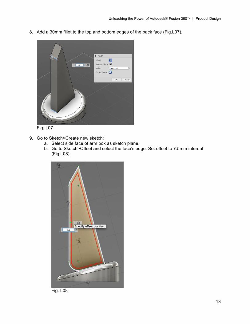
8. Add a 30mm fillet to the top and bottom edges of the back face (Fig.L07).
Fig. L07
9. Go to Sketch>Create new sketch: a. Select side face of arm box as sketch plane. b. Go to Sketch>Offset and select the face’s edge. Set offset to 7.5mm internal
(Fig.L08).
Fig. L08

Unleashing the Power of Autodesk® Fusion 360™ in Product Design
14
c. Pull right side of offset sketch so that it goes over the box (Fig.L09). d. Stop sketch.
Fig. L09
10. Go to Modify>Press Pull, select the offset sketch and pull it to cut through the box (Fig.L10).
Fig. L10
11. Go to Modify>Move, select the front face of the top of the arm and rotate so that it’s perpendicular to the profile (Fig.L11).

Unleashing the Power of Autodesk® Fusion 360™ in Product Design
15
Fig. L11
C. CREATE LAMP’S SHADE
12. Go to Sketch>Create new sketch: a. Select the top inner face of the lamp’s arm as sketch plane. b. Sketch a circle at the center of the face, 30mm diameter (Fig.L12). c. Stop sketch
Fig. L12
13. Go to Modify>Press Pull: a. Select the circle sketch and pull it to create a cylinder about 100mm long. b. Set taper angle to 30deg (Fig.L13). c. Set operation to NEW BODY.
Fig. L13
Unleashing the Power of Autodesk® Fusion 360™ in Product Design
16
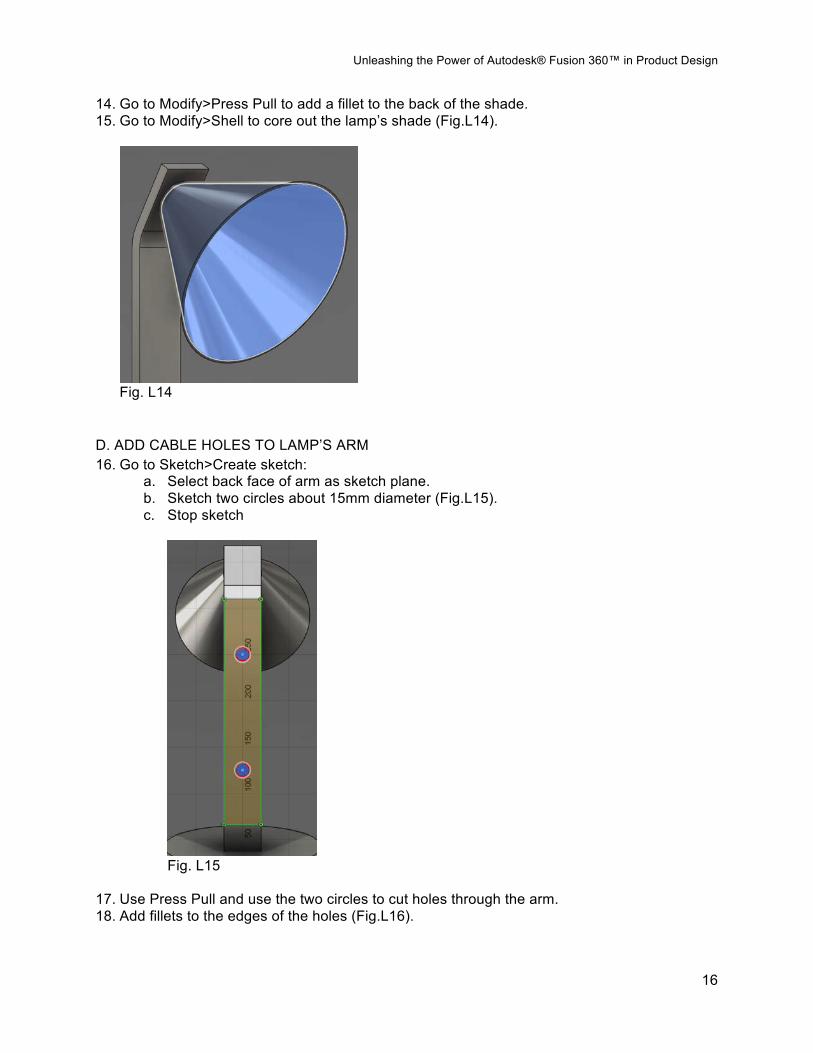
14. Go to Modify>Press Pull to add a fillet to the back of the shade. 15. Go to Modify>Shell to core out the lamp’s shade (Fig.L14).
Fig. L14
D. ADD CABLE HOLES TO LAMP’S ARM 16. Go to Sketch>Create sketch:
a. Select back face of arm as sketch plane. b. Sketch two circles about 15mm diameter (Fig.L15). c. Stop sketch
Fig. L15
17. Use Press Pull and use the two circles to cut holes through the arm. 18. Add fillets to the edges of the holes (Fig.L16).

Unleashing the Power of Autodesk® Fusion 360™ in Product Design
17
Fig. L16
E. CREATE ELECTRICAL CABLE
19. Create a new sketch at the front plane. 20. Create a spline that begins right behind the lamp shade and goes through both holes in the
lamp arm, and extends to the back of the lamp (Fig.L17). **Note: change the visual style to “wireframe” so that you can see the holes. You can do this at the bottom of the screen, by clicking the icon that looks like a computer monitor.
Fig. L17
21. Create another sketch at the top back face of the arm, sketching a circle at the center of the face about 7.5mm diameter (Fig.L18).

Unleashing the Power of Autodesk® Fusion 360™ in Product Design
18
Fig. L18
22. Go to Create>Sweep and create a sweep that uses the circle as profile and the spline as path (Fig.L19).
Fig. L19
F. ADD FINAL FILLETS
23. Use press pull to add fillets to the following parts (Fig.L20): a. Top and bottom edges of arm. b. Side edges of arm c. Front edge of shade d. Bottom of base

Unleashing the Power of Autodesk® Fusion 360™ in Product Design
19
Fig. L20
Congratulations! You have completed the desktop lamp example.

Unleashing the Power of Autodesk® Fusion 360™ in Product Design
20
Example 3: Glass bottle* Video link: http://youtu.be/Vd45bCoXNPw Key highlights:
• Keeping geometry as simple as possible • Maximizing “symmetry” to minimize work • Benefiting from “splines” and “edit form” • Maintaining design intent
*Bottle based on Coca Cola bottle, trademarked by The Coca Cola Company. A. SET BACKGROUND IMAGE
21. Set workspace to “Sculpt” mode. 22. Set viewpoint to Front plane 23. Go to Image>Background canvas:
a. Click on select image and browse for “glass_bottle.jpg” **Note: jpg is included in the files for this class in the AU website.
b. Set opacity to 50% c. Check “display through”
24. Under the tree structure (dropdown list on left side) expand “canvases” folder, right-click on “glass_bottle” and select “calibrate” (Fig. B01).
Fig. B01
a. Click on the top and bottom of the surface and set that distance to “11in” b. Right click on “glass_bottle” again, select “move” and position the image so that the
bottom center of the bottle is at the origin (Fig. B02).

Unleashing the Power of Autodesk® Fusion 360™ in Product Design
21
Fig. B02
B. CREATE BOTTLE
25. Create a new sketch in front plane: a. Draw a “spline” that begins at the bottom of the bottle (making sure it begins on the
“Y” axis), then goes out to the side of the bottle and makes its way up until before the mouth of the bottle (Fig. B03). **Note: as with any spline-based geometry, make sure you use as few points as possible in order to obtain nice surface continuity. As a point of reference, the spline used in this tutorial has 10 vertices.
Fig. B03
b. Refine spline as needed to match the background image. c. Stop sketch

Unleashing the Power of Autodesk® Fusion 360™ in Product Design
22
26. Go to Create>Revolve: a. Select spline as profile b. Select Z-axis (vertical green line) as axis c. Set horizontal faces to “18” d. Set vertical faces to “4” e. Set symmetry to “circular” f. Set symmetric faces to "6” g. Set to “new body” (Fig. B04)
Fig. B04
C. CREATE CENTER RIBBON
27. Go to Modify>Edit form: a. Set selection filter to “faces” b. Select the faces in the ribbon area, HOLD ALT key and use the scaling tab in the
center of the slide tool (it looks like a doughnut) to scale down that portion while adding additional edges (Fig. B05).
Fig. B05

Unleashing the Power of Autodesk® Fusion 360™ in Product Design
23
c. Switch selection filter to “edge” and move/scale the edges to refine the ribbon (Fig. B06). **Note: make sure you double-click each edge to select the whole chain.
Fig. B06
D. ADD VERTICAL RIDGES
28. Go to Modify>Edit form: a. Set selection filter to edges b. Select mid top and mid bottom edges sitting at the right end of the bottle (Fig. B07).
Fig. B07

Unleashing the Power of Autodesk® Fusion 360™ in Product Design
24
c. Move edges left (into the bottle) about 5mm (Fig. B08).
Fig. B08
d. Repeat steps b and c with the same of set edges three faces to the left (Fig. B09).
Fig. B09
E. CREATE BOTTLE’S MOUTH
29. Create a new sketch at the front plane and sketch a spline that follows the mouth’s contour (Fig. B10).
30. Use that spline to revolve the mouth, setting it to 24 faces.
Fig. B10
Unleashing the Power of Autodesk® Fusion 360™ in Product Design
25
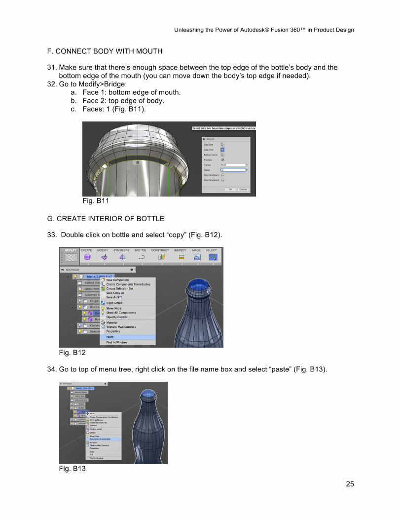
F. CONNECT BODY WITH MOUTH
31. Make sure that there’s enough space between the top edge of the bottle’s body and the bottom edge of the mouth (you can move down the body’s top edge if needed).
32. Go to Modify>Bridge: a. Face 1: bottom edge of mouth. b. Face 2: top edge of body. c. Faces: 1 (Fig. B11).
Fig. B11
G. CREATE INTERIOR OF BOTTLE
33. Double click on bottle and select “copy” (Fig. B12).
Fig. B12
34. Go to top of menu tree, right click on the file name box and select “paste” (Fig. B13).
Fig. B13

Unleashing the Power of Autodesk® Fusion 360™ in Product Design
26
35. Go to the menu tree, expand “bodies”, right-click on the first bottle body and select “selectable/unselectable”
36. Go to Modify>Edit Form: a. Set selection filter to whole body b. Select bottle copy and scale down uniformly to 0.95 (using the center handle that
looks like a doughnut) (Fig. B14).
Fig. B14
c. Stretch model vertically so that the contours align with the outside of the bottle (Fig. B15).
Fig. B15
H. CONNECT BOTH BODIES AND CONVERT TO SOLID
37. Go back to the original body and make it selectable again. 38. Go to Modify>Bridge and connect the top edge of the interior surface with the top edge of
the exterior surface, setting number of faces to “3” (Fig. B16).

Unleashing the Power of Autodesk® Fusion 360™ in Product Design
27
Fig. B16
39. Go to Modify>Convert and select the body to create a solid version of it. Congratulations! You have completed the glass bottle.
Unleashing the Power of Autodesk® Fusion 360™ in Product Design
28
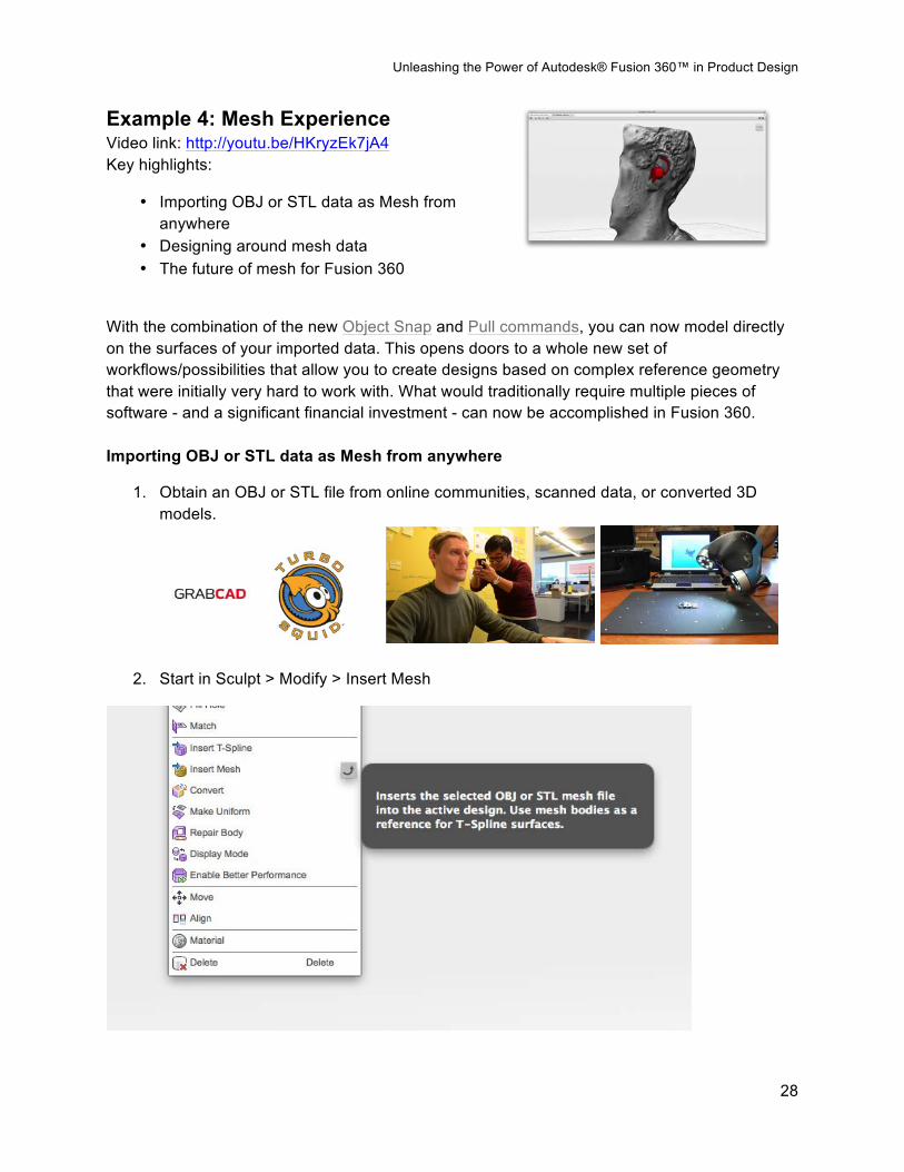
Example 4: Mesh Experience Video link: http://youtu.be/HKryzEk7jA4 Key highlights:
• Importing OBJ or STL data as Mesh from anywhere
• Designing around mesh data • The future of mesh for Fusion 360
With the combination of the new Object Snap and Pull commands, you can now model directly on the surfaces of your imported data. This opens doors to a whole new set of workflows/possibilities that allow you to create designs based on complex reference geometry that were initially very hard to work with. What would traditionally require multiple pieces of software - and a significant financial investment - can now be accomplished in Fusion 360. Importing OBJ or STL data as Mesh from anywhere
1. Obtain an OBJ or STL file from online communities, scanned data, or converted 3D models.
2. Start in Sculpt > Modify > Insert Mesh

Unleashing the Power of Autodesk® Fusion 360™ in Product Design
29
Designing around mesh data
1. Start by creating sculpt Face, or Sculpt body.
2. Create the sculpt face directly on the mesh body with Object snap checked in the tool box.
3. OR create the sculpt body around the mesh body so it is as close to the body as possible.

Unleashing the Power of Autodesk® Fusion 360™ in Product Design
30
4. Use Pull command and select the entire sculpt body or individual vertices to make the sculpt vertices snap to the closest surface of the mesh body, resulting in a “shrink wrap” behavior.

Unleashing the Power of Autodesk® Fusion 360™ in Product Design
31
5. Edit the sculpt body until you reach a desirable result.

Unleashing the Power of Autodesk® Fusion 360™ in Product Design
32
The Future of Mesh for Fusion 360 So what is Phase 2? Mesh data modification and repair. This will be extremely useful for incomplete datasets, or datasets that contain inconsistencies, which make it difficult to move downstream. Having the ability to bring in scanned data, modify or repair it, and then use it as the design itself or design something custom fitted to that dataset will really allow users to seamlessly turn ideas into reality. THAT is where we want to take Fusion 360, and we'll going to make it happen. From Mesh to re-topologized Sculpt body to solid body