urban search & rescue project hints & additional information
TRANSCRIPT

Urban Search & Rescue ProjectHints & Additional Information
http://www.isd.mel.nist.gov/projects/USAR/
Dead-Reckoning
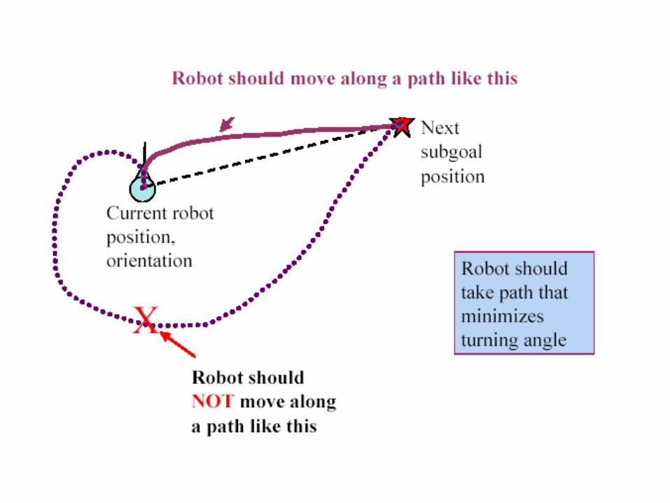
Dead Reckoning is the process of estimating your position by advancing a known position using direction, speed, time and distance to be traveled. In other words figuring out where you will be at a certain time if you hold the speed, time and direction you plan to travel.
Dead-reckoning error is important in your project!
Design your robot & drive train so that it can translate and rotate with accuracy.
Translate: Write a function that takes as input a number (in inches), waits for the start button to be pressed, waits five seconds, and then accurately drives the robot forward by the inputted value in inches (or reverse if the inputted number was negative).
Rotate: Write a function that takes as input a number (in degrees), waits for the start button to be pressed , waits five seconds, and then accurately rotates the robot counter-clockwise by the inputted value in degrees (or clockwise if the inputted number was negative).
Measure the accrued dead-reckoning error after initial robot design is complete
Mark the location of the wheels. Drive your robot forward & reverse for a fixed distance 9 times and report your findings.
Mark the location of the wheels. Drive the robot forward for a fixed distance, turn ninety degrees to the left, repeat three more times to make a square. Drive around the square five times. Report what happens.
Position
Odometer systemCount the number of revolutionsCalculate distance based on wheel diameterHardware
Infrared emitter and detector (shield them)Interrupter, detects when the IR beam is blockedReflector, detects when the IR beam bounces off an object
Rotary encodersOutputs a pulse based on rotation of shaftDifferent resolutions availableSome indicate direction of rotation
Software Count pulses from the sensor Interpret the data to calculate actual distances Need to consider error and cumulative drift Perhaps use readings from multiple devices and
use average
Direction
Lego motors are not identical due to variations in manufacture. A slight imbalance in motor output is important because even small variations in wheel speed can result in the robot straying from a straight-line path.
Differential steering
Wheels are independently driven (separate encoders)
Turn by changing the relative speeds of the wheels
Monitor rotation and use equations to determine direction
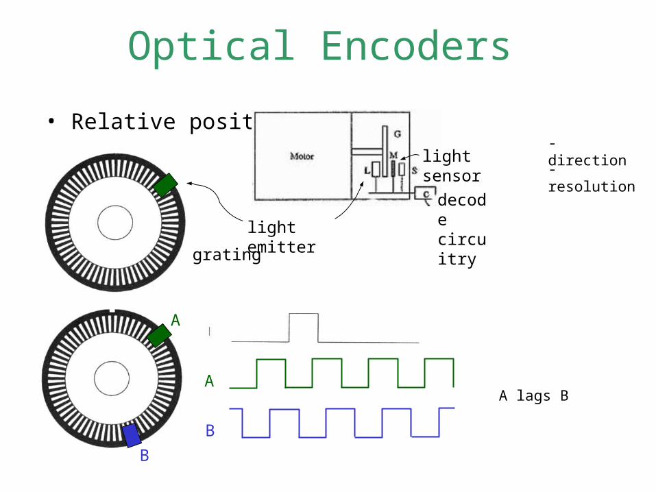
Optical Encoders
• Relative position - direction
- resolution
grating
light emitter
light sensor
decode circuitry
A
B
A
B
A lags B
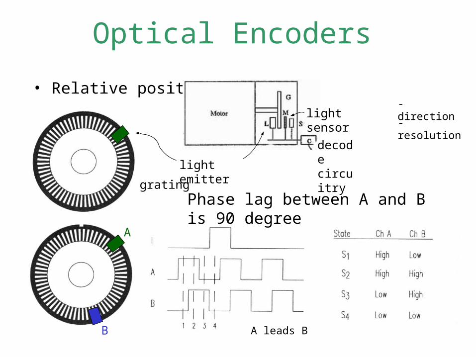
Optical Encoders
• Relative position - direction
- resolution
grating
light emitter
light sensor
decode circuitry
A
B A leads B
Phase lag between A and B is 90 degree
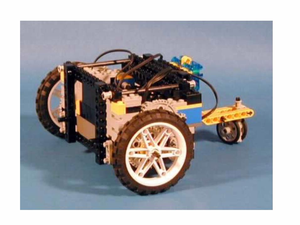
Structural Design
Make liberal use of Lego's pin and beam construction elements to prevent vibration, wobbling or distortion of the robot's frame or drive shafts while in motion. This degrades the wheel alignment introducing both random and systematic error to the navigation problem.
To provide further stability, the robot's heaviest component, the Handyboard could be positioned as low as possible within the constraints of the overall design. It will be a good idea to put the center of gravity slightly behind the main wheels so that the tail wheel is lightly loaded, but not so much that the system tips forward when it stops suddenly.
Trade-off between accuracy and traction.
• Hard and narrow wheels provide better accuracy.
• Wide and soft wheels provide better traction
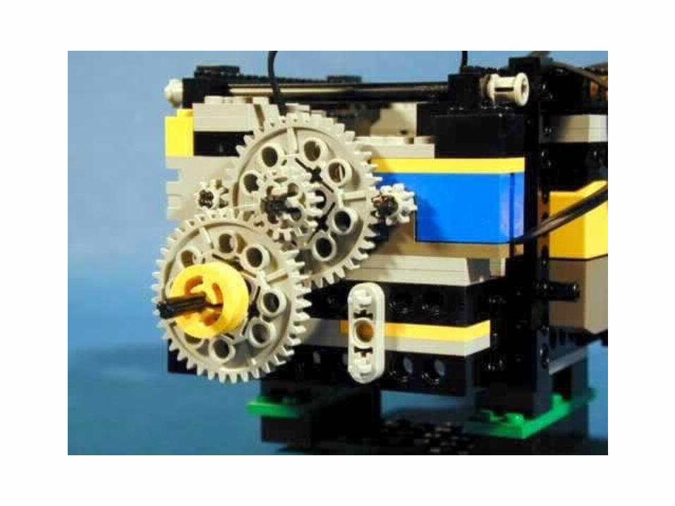
Your design should be a compromise between the geometry imposed by the Lego components and the need to obtain as fine a resolution from the wheel encoders as possible. The more accurately the robot can measure wheel rotation, the more accurately it can dead-reckon. Couple each motor to an encoder through a 1:1 gear train that ensures they are synchronized.
If your gear train provides a 9 to 1 reduction ratio from motor to wheels and there are 16 pulses on your encoder (The Lego rotation sensors measure rotation with an accuracy of 22.5 degrees,16 intervals per revolution), for each rotation of the wheel, the encoder rotates 27 times allowing the system to measure 9x16=144 samples per revolution (Make sure that you don’t exceeded the 500 RPM sample rate supported by the Lego rotation) sensors .
Measure the diameter of the tire and calculate the distance for each encoder “click” e.g. 8.16 cm diameter tires means that each "click" of the encoders covers a distance of 8.16x3.1415/144=0.18 cm.
Lego sensors are not identical due to variations in manufacture: If using more then one encoder, set each encoder and set each encoder threshold separately. Due to differences in photocells, LED lights, and so on, the readings you obtain from one encoder won't necessarily be the same readings you'll get from the other encoder.
Sampling rate v.s. sensor resolution:As the motor is running, the encoder is turning very quickly and the photocell won't have time to reach its "totally-dark" value before it is again exposed to the LED light. And while the photocell is exposed to light, it won't have time to reach its maximum “totally-light" value before the light source is removed.
Record 100 consecutive values while the wheels are turning. Report what you see.
Moment of Inertia
When you turn off the motor, the robot will not come to an immediate halt.Reverse the motor for a fraction of a second before turning it off.
While moving forward and trying to make a 90-degree turn, inner wheel turns in reverse and due to moment of inertia, the motor won’t be able to execute reverse movement as quickly asouter wheel’s forward movement. To solve this problem, have the car, just before it is about to change its direction of movement, come to a complete stop for a second.
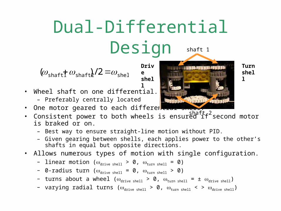
Dual-Differential Design
• Wheel shaft on one differential.– Preferably centrally located
• One motor geared to each differential shell.• Consistent power to both wheels is ensured if second motor is braked or on.
– Best way to ensure straight-line motion without PID.– Given gearing between shells, each applies power to the other’s shafts in equal but
opposite directions.
• Allows numerous types of motion with single configuration.– linear motion (drive shell > 0, turn shell = 0)– 0-radius turn (drive shell = 0, turn shell > 0)– turns about a wheel (drive shell > 0, turn shell = ± drive shell)– varying radial turns (drive shell > 0, turn shell < > drive shell)
shellshaft2shaft1 2/)( Drive shell
shaft 2
shaft 1
Turn shell

http://www.cs.dartmouth.edu/~robotlab/robotlab/courses/cs54-2001s/dualdiff.html
http://www.owlnet.rice.edu/~elec201/Book/legos.html#SECTION001423000000000000000
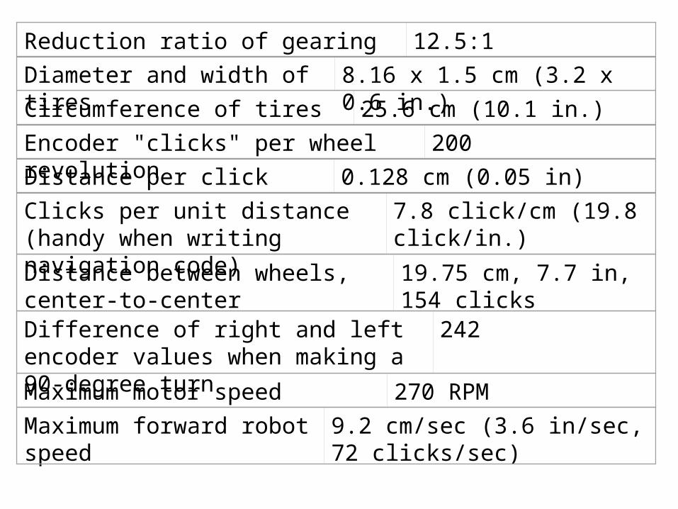
Reduction ratio of gearing 12.5:1
Diameter and width of tires 8.16 x 1.5 cm (3.2 x 0.6 in.)
Circumference of tires 25.6 cm (10.1 in.)
Encoder "clicks" per wheel revolution 200
Distance per click 0.128 cm (0.05 in)
Clicks per unit distance (handy when writing navigation code)
7.8 click/cm (19.8 click/in.)
Distance between wheels, center-to-center
19.75 cm, 7.7 in, 154 clicks
Difference of right and left encoder values when making a 90-degree turn
242
Maximum motor speed 270 RPM
Maximum forward robot speed 9.2 cm/sec (3.6 in/sec, 72 clicks/sec)
http://rossum.sourceforge.net/tools/MotionApplet/
Control to avoid dead-reckoning error
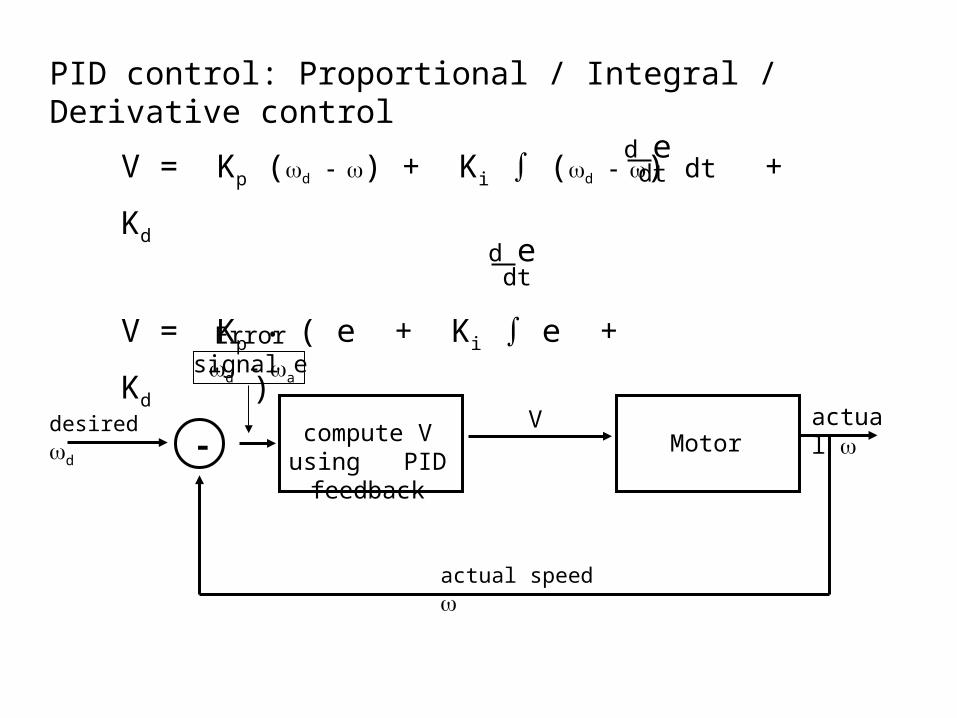
In the PID control, a controller monitors the error in the system (its deviation from some desired value, or set point) and makes corrections based on three criteria. The Proportional response is based on the magnitude of the observed error, the Integral of that error (error accumulated over time), and the Derivative of the error (the rate at which the error changes over time). The PID control can be the basis of the steering system used to control your robot and keep it following a straight line.
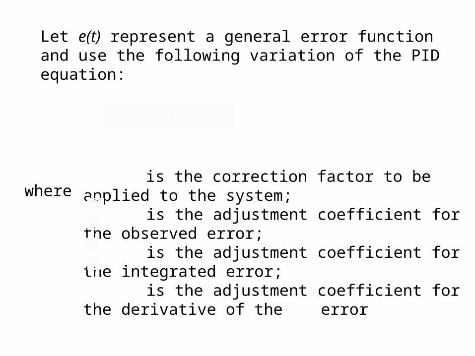
Let e(t) represent a general error function and use the following variation of the PID equation:
where
is the correction factor to be applied to the system; is the adjustment coefficient for the observed error; is the adjustment coefficient for the integrated error; is the adjustment coefficient for the derivative of the error
One common use of the PID technique is in controlling motor speed. Two sets of PID calculations can be used to maintain a constant speed for each motor. Feedback from each sensor can be used as input into the PID calculation for the corresponding motor. Additional calculations can combine sensor inputs to track data such as orientation and position, coordinating the motors and adjusting their respective speeds as needed.
Alternatively, a less ambitious approach can be used. Rather than looking at the problem as a matter of controlling two motors, look at the robot as a whole. So controlling the absolute speed of each motor is not as important as controlling their speed relative to each other. This approach focuses on the robot's path, and disregards its speed. The important thing is simply that the vehicle goes straight.
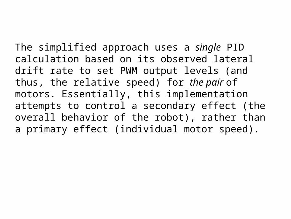
The simplified approach uses a single PID calculation based on its observed lateral drift rate to set PWM output levels (and thus, the relative speed) for the pair of motors. Essentially, this implementation attempts to control a secondary effect (the overall behavior of the robot), rather than a primary effect (individual motor speed).
PID control: Proportional / Integral / Derivative control
desired dV
Motoractual
actual speed
- compute V using PID feedback
d a
Error signal e
V = Kp (d ) + Ki ∫ (d ) dt + Kd
V = Kp • ( e + Ki ∫ e + Kd )
d e dt
d e dt
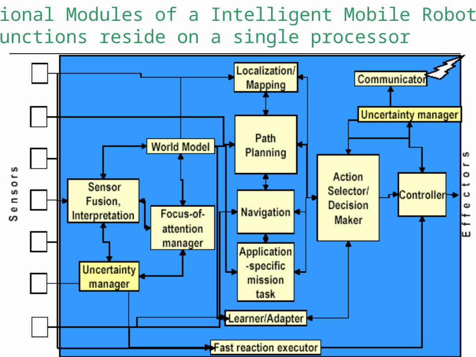
Functional Modules of a Intelligent Mobile Robot All functions reside on a single processor

Functional Modules Related to Control Architecture
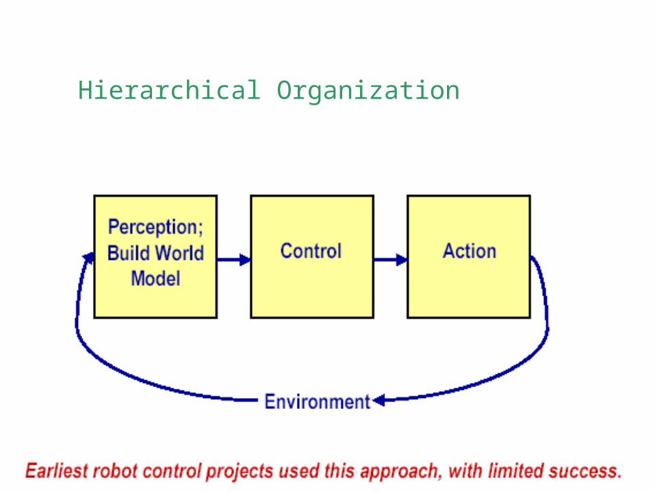
Hierarchical Organization
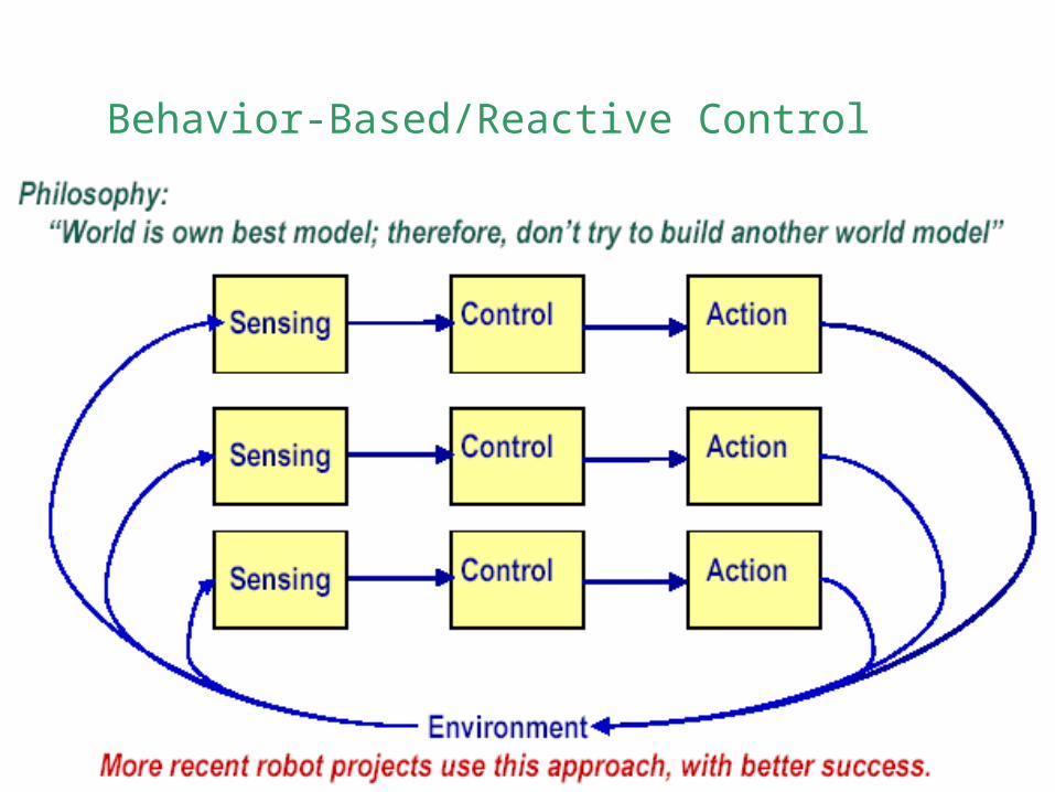
Behavior-Based/Reactive Control
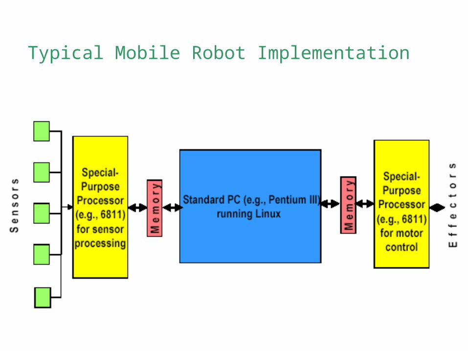
Typical Mobile Robot Implementation
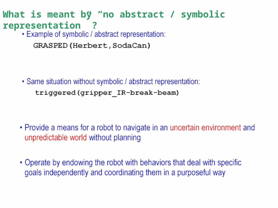
What is meant by “no abstract / symbolic representation” ?
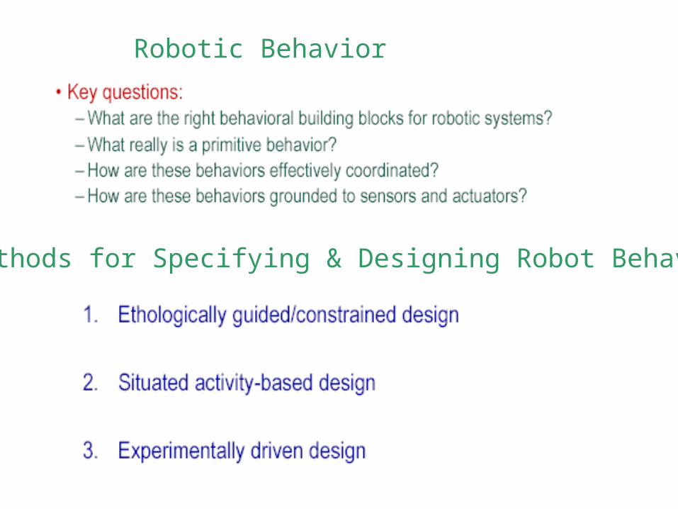
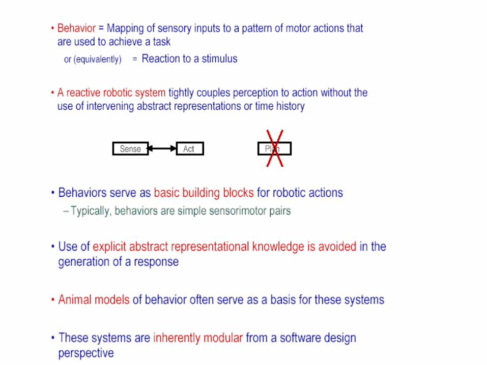
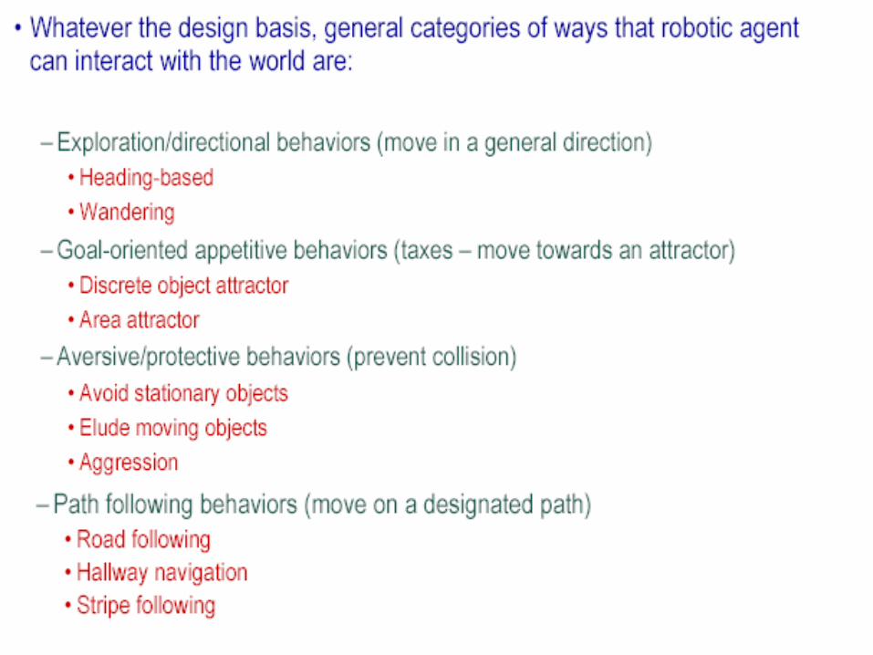
Robotic Behavior
3 Methods for Specifying & Designing Robot Behavior
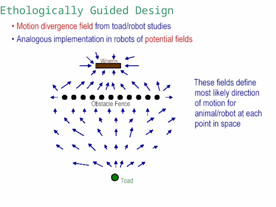
1. Ethologically Guided Design
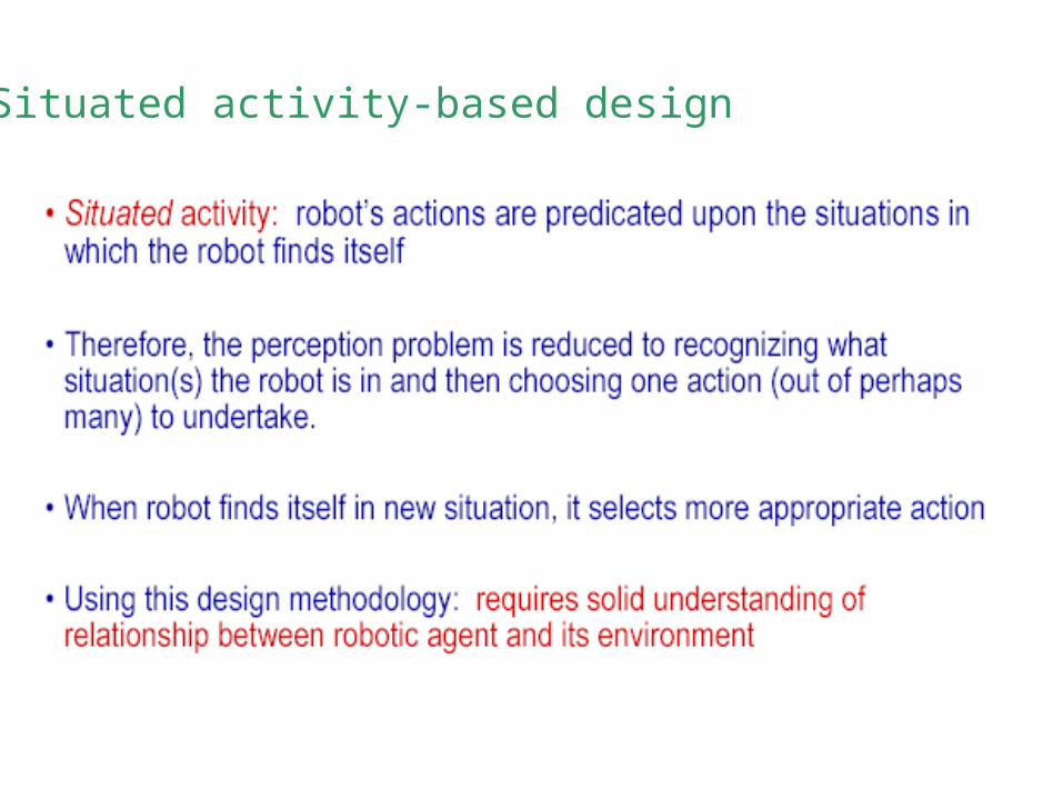
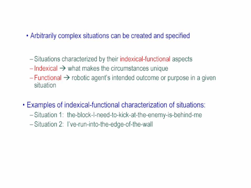
2. Situated activity-based design

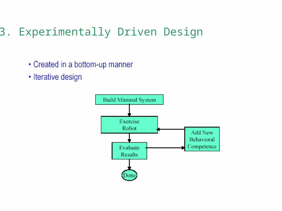
3. Experimentally Driven Design
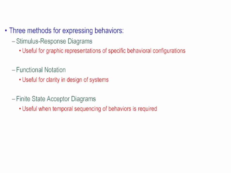
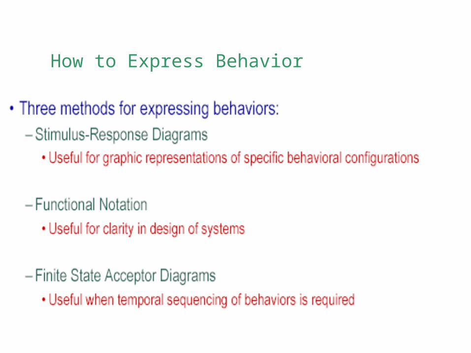
How to Express Behavior
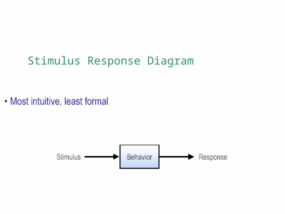
Stimulus Response Diagram
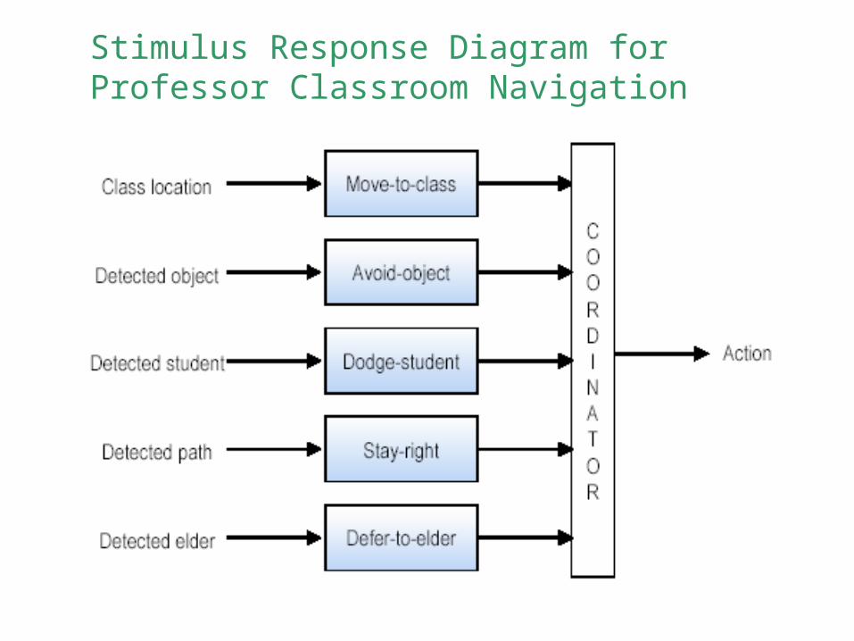
Stimulus Response Diagram for Professor Classroom Navigation
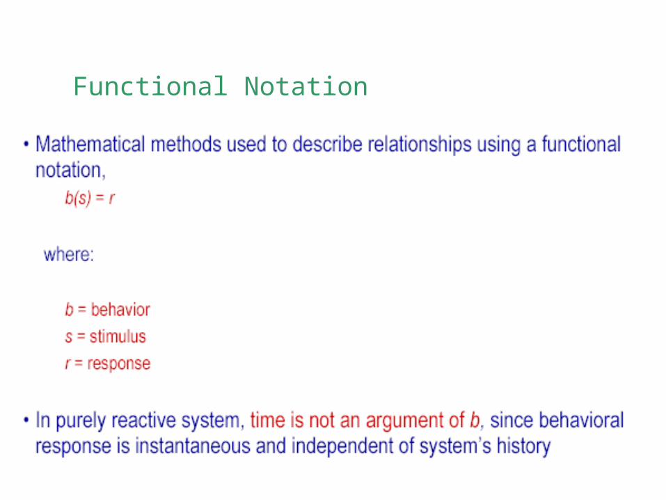
Functional Notation
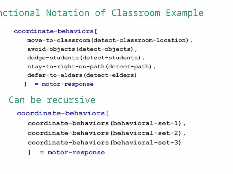
Functional Notation of Classroom Example
Can be recursive

Finite State Acceptor Diagrams
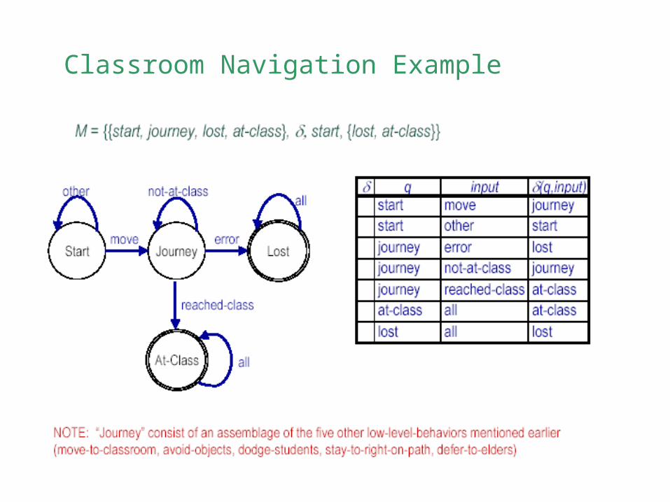
Classroom Navigation Example
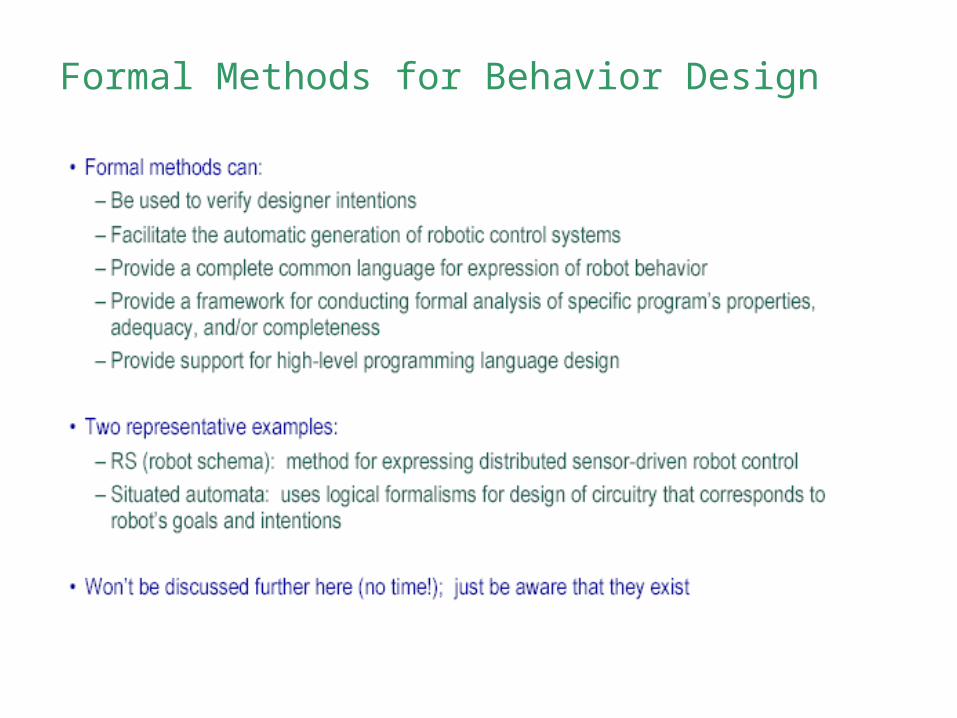
Formal Methods for Behavior Design
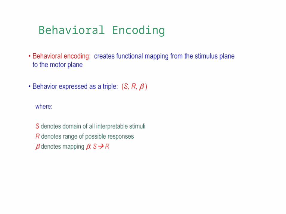
Behavioral Encoding
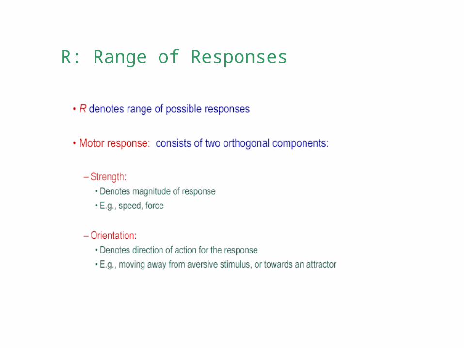
R: Range of Responses

your search & rescue robot, 3 DOF r = (x, y, )

S: Stimulus
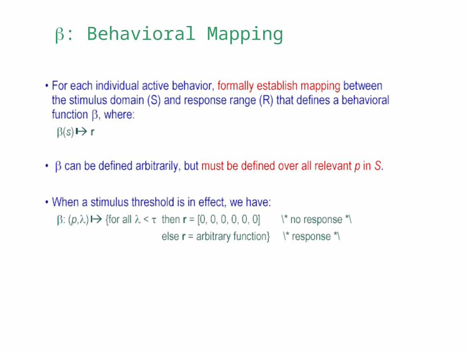
: Behavioral Mapping
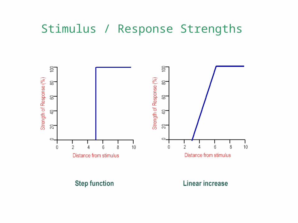
Stimulus / Response Strengths
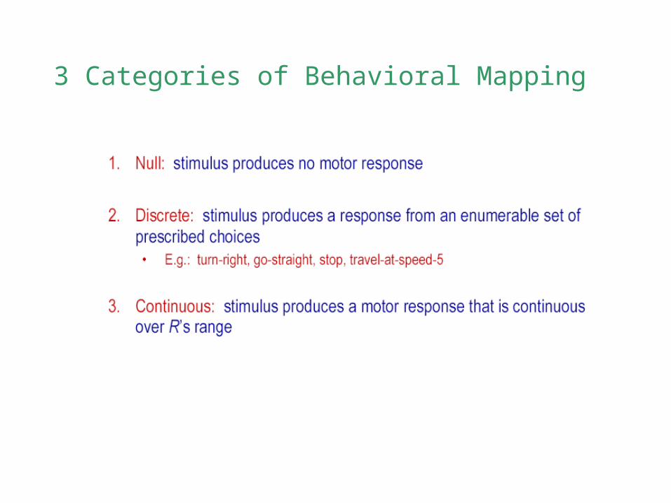
3 Categories of Behavioral Mapping
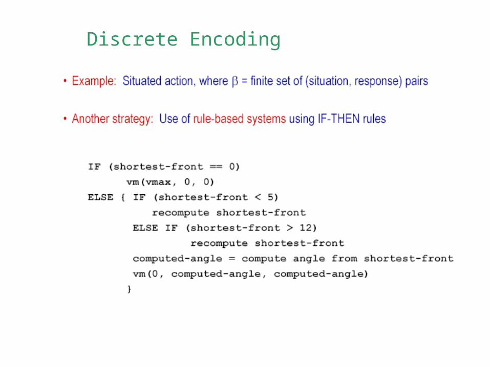
Discrete Encoding
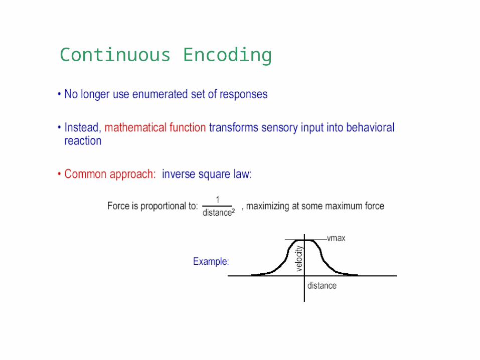
Continuous Encoding