u.s. epr final safety analysis report - nrc.gov · u.s. epr final safety analysis report tier 2...
TRANSCRIPT

U.S. EPR FINAL SAFETY ANALYSIS REPORT
3E.1.16 Fuel Building Hardened Shell Walls from Top of the Nuclear Island Basemat to Grade
This critical section presents the analysis and structural design methodology and design results of the Fuel Building (FB) Hardened Shell Walls from Top of the Nuclear Island Basemat to Grade. The FB is described in Section 3.8.4.1.2. The dimensions of the FB are shown on Figure 3B-27—Fuel Building Dimensional Section A-A to Figure 3B-29—Fuel Building Dimensional Section C-C.
The FB is a safety-related, Seismic Category I, reinforced concrete structure that is supported by the Nuclear Island (NI) Foundation Basemat structure, as described in Section 3.8.
The FB Hardened Shell Walls from Top of the Nuclear Island Basemat to Grade includes the East, West, and South Shield Walls of the FB Hardened Shell. The wall buttress at the South wall is included and is considered as a T-Beam section. An isometric view of the FB Hardened Shell Walls from Top of the Nuclear Island Basemat to Grade is shown on Figure 3E.1.16-1—Isometric View FB Hardened Shell Walls from Top of Nuclear Island Basemat to Grade. Design details for the following FB Hardened Shell Walls from Top of the Nuclear Island Basemat to Grade subcomponents are within the scope of this critical section:
● Figure 3E.1.16-2—FB Hardened Shell East Wall 16A.
● Figure 3E.1.16-3—FB Hardened Shell East Wall 16B.
● Figure 3E.1.16-4—FB Hardened Shell South Wall 16C.
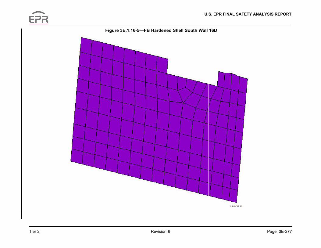
● Figure 3E.1.16-5—FB Hardened Shell South Wall 16D.
● Figure 3E.1.16-6—FB Hardened Shell West Wall 16E.
● Figure 3E.1.16-7—FB Hardened Shell West Wall 16F.
● Figure 3E.1.16-8—FB Hardened Shell West Wall 16G.
Tier 2 Revision 6 Page 3E-263
● Figure 3E.1.16-9—FB Hardened Shell West Wall 16H.
3E.1.16.1 Model
The finite element ANSYS static model of the NI Common Basemat Structures (ANSYS NI static model) described in Sections 3.8.1.4.1 and 3E.1 is used to design the FB Hardened Shell Walls from Top of the Nuclear Island Basemat to Grade.
The FB Hardened Shell Walls from Top of the Nuclear Island Basemat to Grade are modeled using SHELL43 elements. The element size in these wall areas is approximately 5 ft by 5 ft. The shield wall buttress is modeled using Beam44 elements.

U.S. EPR FINAL SAFETY ANALYSIS REPORT
The nomenclature for the forces and moments results of the ANSYS NI static model is shown on Figure 3E.1-1. The moments obtained from ANSYS NI static model results have the opposite sign convention from those obtained from CivilFEM. The sign convention for ANSYS results is shown on Figure 3E.1-1, and the sign convention for CivilFEM results is shown on Figure 3E.1-2.
3E.1.16.2 Load Combinations and Loads
The load combinations applied to the FB The FB Hardened Shell Walls from Top of the Nuclear Island Basemat to Grade are described in Section 3.8.4.3. The design of the FB Hardened Shell Walls from Top of the Nuclear Island Basemat to Grade is achieved using the results obtained from the model pertaining to the E-Series load combinations shown in Table 3E.1-4. This critical section is also designed for the soil analysis cases in Table 3.7.1-6.
Independent loads considered in the ANSYS NI static model for the FB Hardened Shell Walls from Top of the Nuclear Island Basemat to Grade are shown in Table 3E.1-2 and described in Sections 3.8.4.3.1 and 3E.1. Independent loads not considered in the ANSYS NI static model are shown in Table 3E.1-3.
Missing loads considered in the design include accidental torsion and differential settlement/construction sequence.
The additional loads created from accidental torsion are part of the safe shutdown earthquake load. A separate analysis was performed to estimate the effects of accidental torsional loads. Based on the results of the analysis, additional in-plane shear and axial loads are included in the design of the FB Hardened Shell Walls from Top of the Nuclear Island Basemat to Grade.
A separate structural evaluation is performed to determine the effects of differential settlement/construction. The additional design forces and moments from the settlement effects are included in the design. Differential settlement/construction sequence is described in Section 3.8.5.4.2.
Tier 2 Revision 6 Page 3E-264
3E.1.16.3 Analysis and Design Methods
The methodology used for the structural analysis and design of the FB Hardened Shell Walls from Top of the Nuclear Island Basemat to Grade is to determine the reinforcement configuration using forces and moments generated from the finite element ANSYS NI static model. The design of the FB Hardened Shell Walls from Top of the Nuclear Island Basemat to Grade is performed using the applicable codes, standards, and specifications described in Section 3.8.4.2.
The FB Hardened Shell Walls from Top of the Nuclear Island Basemat to Grade are designed for the resultant forces and moments determined based on the applied
U.S. EPR FINAL SAFETY ANALYSIS REPORT
loading and soil conditions. CivilFEM is used to extract forces and moments from the ANSYS NI static model for a given load combination. Once the forces and moments are obtained, the material properties are checked and adjusted as needed, additional loads are added, and design function of CivilFEM is run to obtain the required reinforcement. If high reinforcement values are obtained in a concentrated area, the areas of steel results are averaged to better reflect the behavior of the reinforced concrete.
3E.1.16.4 Critical Section Design
The structural design provides reinforcement to resist element forces and moments for each of the FB Hardened Shell Walls from Top of the Nuclear Island Basemat to Grade. The FB Hardened Shell Walls from Top of the Nuclear Island Basemat to Grade are designed so that each is capable of carrying the applied design loadings provided they are constructed in accordance with the material properties in Section 3E.1 and the section geometry and reinforcing described in this critical section.
The governing design data for the FB Hardened Shell Walls from Top of the Nuclear Island Basemat to Grade are shown in Table 3E.1.16-1—Governing Design Data for FB Hardened Shell Walls from Top of the Nuclear Island Basemat to Grade. The governing design data for the FB Hardened Shell Buttress is shown in Table 3E.1.16-2—Governing Design Data for FB Hardened Shell Buttress.
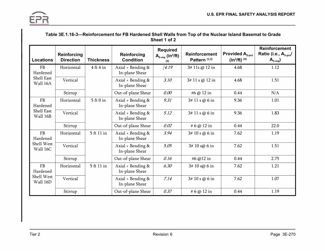
A key plan of the FB Hardened Shell Walls from Top of the Nuclear Island Basemat to Grade is shown on Figure 3E.1.16-10—Key Plan FB Hardened Shell Walls from Top of the Nuclear Island Basemat to Grade. The minimum required area of steel reinforcement for the FB Hardened Shell Walls from Top of the Nuclear Island Basemat to Grade is shown in Table 3E.1.16-3—Reinforcement for FB Hardened Shell Walls from Top of the Nuclear Island Basemat to Grade and Table 3E.1.16-4—Reinforcement for FB Hardened Shell Buttress. Table 3E.1.16-3 and Table 3E.1.16-4 also show the area of steel reinforcement in the design based on the reinforcement configurations shown on Figure 3E.1.16-11—Reinforcement Details of FB Hardened Shell East Wall 16A (Section 7-7) through Figure 3E.1.16-20—Reinforcement Details
Tier 2 Revision 6 Page 3E-265
of FB Hardened Shell Buttress.
Use of reinforcement configurations (including bar size, spacing, and clear cover) different from those shown on Figure 3E.1.16-11 through Figure 3E.1.16-20 are acceptable, provided they meet or exceed the minimum required area of steel reinforcement shown in Table 3E.1.16-3 and Table 3E.1.16-4.

U.S. EPR FINAL SAFETY ANALYSIS REPORT
Table 3E.1.16-1—Governing Design Data for FB Hardened Shell Walls from Top of the Nuclear Island Basemat to Grade
Sheet 1 of 2
Locations LC(1) SC(1) Design Condition
Governing Design Data(2)(3)(4)(5)
MXU(6) MYU
(6) TX TY TXY NX NY
k-ft/ft k-ft/ft k/ft k/ft k/ft k/ft k/ftFB Hardened
Shell East Wall 16A
E_06_04_1X 5AH Bending + Axial (Horizontal) * 14 * 95 * * *
E_06_01_1X 5AH Bending + Axial (Vertical) 334 * -66 * * * *
E_06_04_1x 5AH In-plane Shear (Horizontal) * * -29 * 298 * *
E_06_04_1x 5AH In-plane Shear (Vertical) * * * 4 298 * *
E_06_01_1X 5AH Out-of-plane Shear * * -35 7 * 39 11
FB Hardened Shell East Wall
16B
E_06_32_1X 5AH Bending + Axial (Horizontal) * -260 * 490 * * *
E_06_24_2X 5AH Bending + Axial (Vertical) -118 * 167 * * * *
E_06_24_2X 5AH In-plane Shear (Horizontal) * * 379 * 371 * *
E_06_24_1X 5AH In-plane Shear (Vertical) * * * -80 333 * *
E_06_32_1X 5AH Out-of-plane Shear * * -561 432 * 3 13
FB Hardened Shell West Wall
16C
E_06_08_2X 1N5AH Bending + Axial (Horizontal) * 518 * 37 * * *
E_06_08_2X 5AH Bending + Axial (Vertical) 464 * 188 * * * *
E_06_08_2X 1N5AH In-plane Shear (Horizontal) * * -62 * 228 * *
E_06_08_2X 1N5AH In-plane Shear (Vertical) * * * 14 227 * *
E_13_20_3a 5AH Out-of-plane Shear * * -44 -78 * 144 16
Tier 2 Revision 6 Page 3E-266

U.S. EPR FINAL SAFETY ANALYSIS REPORT
FB Hardened Shell West Wall
16D
E_06_32_2X 5AH Bending + Axial (Horizontal) * -310 * 259 * * *
E_06_08_2X 5AH Bending + Axial (Vertical) 334 * 379 * * * *
E_06_32_2X 4UM In-plane Shear (Horizontal) * * -413 * 276 * *
E_13_19_3a 5AH In-plane Shear (Vertical) * * * -102 241 * *
E_06_08_2X 5AH Out-of-plane Shear * * -301 284 * 124 37
FB Hardened Shell West Wall
16E
E_06_32_1X 5AH Bending + Axial (Horizontal) * -327 * 474 * * *
E_06_24_2X 5AH Bending + Axial (Vertical) -288 * 260 * * * *
E_06_32_2X 5AH In-plane Shear (Horizontal) * * -327 * 201 * *
E_06_24_2X 5AH In-plane Shear (Vertical) * * * 162 336 * *
E_06_24_2X 5AH Out-of-plane Shear * * -216 455 * 47 71
FB Hardened Shell South Wall
16F
E_06_32_1X 4UM Bending + Axial (Horizontal) * -133 * 194 * * *
E_06_21_2X 5AH Bending + Axial (Vertical) -214 * 106 * * * *
E_06_32_1X 4UM In-plane Shear (Horizontal) * * -453 * 252 * *
E_06_03_1x 1N5AH In-plane Shear (Vertical) * * * 183 288 * *
E_06_21_2X 5AH Out-of-plane Shear * * 153 -43 * 131 10
FB Hardened Shell South Wall
16G
E_06_32_1X 4UM Bending + Axial (Horizontal) * -505 * 166 * * *
E_06_24_2X 5AH Bending + Axial (Vertical) -317 * 72 * * * *
E_06_32_1X 4UM In-plane Shear (Horizontal) * * -328 * 419 * *
E_06_24_1X 5AH In-plane Shear (Vertical) * * * -151 435 * *
E_06_24_1X 5AH Out-of-plane Shear * * -235 174 * 18 114
Table 3E.1.16-1—Governing Design Data for FB Hardened Shell Walls from Top of the Nuclear Island Basemat to Grade
Sheet 2 of 2
Locations LC(1) SC(1) Design Condition
Governing Design Data(2)(3)(4)(5)
MXU(6) MYU
(6) TX TY TXY NX NY
k-ft/ft k-ft/ft k/ft k/ft k/ft k/ft k/ft
Tier 2 Revision 6 Page 3E-267

U.S. EPR FINAL SAFETY ANALYSIS REPORT
Notes:
1. LC is the governing load combination, SC is the governing soil analysis case.
2. (–) indicates compression, (+) indicates tension.
3. CivilFEM forces and moments (averaged).
4. TX is axial in the x-direction. TY is axial in the y-direction. TXY is in-plane shear. NX is out-of-plane shear through the x-axis. NY is out-of-plane shear through the y-axis.
5. (*) Not applicable for indicated reinforcement.
6. MX is bending moment about the y-axis. MY is bending moment about the x-axis. MXY is twisting moment. MX is absolute summed with MXY to obtain MXU, the same is done for MY and MXY to obtain MY. See Section 3E.1.1 for additional details.
Tier 2 Revision 6 Page 3E-268

U.S. EPR FINAL SAFETY ANALYSIS REPORT
Notes:
1. LC is the governing load combination, SC is the governing soil analysis case.
2. (–) indicates compression, (+) indicates tension.
3. CivilFEM forces and moments (unaveraged).
4. PZ is axial along the x-axis, VY is shear along the y-axis, VZ is shear about the z-axis, MY is bending moment about the y-axis, MZ is bending moment about the z-axis, TX is torsion about the x-axis.
5. (*) Not applicable for indicated reinforcement.
Table 3E.1.16-2—Governing Design Data for FB Hardened Shell Buttress
Locations LC(1) SC(1)Design
Condition
Governing Design Data(2)(3)(4)(5)
PX (kips) VY (kips) VZ (kips)MY
(k-ft/ft)MZ
(k-ft/ft)TX
(k-ft)Buttress
16HE_09_07_1a_beams 1N5AH Axial 344 * * * * *
E_06_08_2x_beams 1N5AH Axial -3366 * * * * *
E_06_08_2x_beams 1N5AH Shear * 1313 * * * *
E_06_08_2x_beams 1N5AH Shear * * 2482 * * *
E_09_07_1a_beams 1N5AH Bending * * * 7632 495 *
E_06_08_2x_beams 1N5AH Torsion * * * * * 9630
Tier 2 Revision 6 Page 3E-269
U.S. EPR FINAL SAFETY ANALYSIS REPORT
Table 3E.1.16-3—Reinforcement for FB Hardened Shell Walls from Top of the Nuclear Island Basemat to Grade Sheet 1 of 2
LocationsReinforcing
Direction ThicknessReinforcing Condition
Required AS-req (in2/ft)
(3)
Reinforcement Pattern (1,2)
Provided AS-pro (in2/ft) (4)
Reinforcement Ratio (i.e., AS-pro/
AS-req)FB
Hardened Shell East Wall 16A
Horizontal 4 ft 4 in Axial + Bending & In-plane Shear
[4.19 3# 11s @ 12 in 4.68 1.12
Vertical Axial + Bending & In-plane Shear
3.10 3# 11 s @ 12 in 4.68 1.51
Stirrup Out-of-plane Shear 0.00 #6 @ 12 in 0.44 N/A
FB Hardened Shell East Wall 16B
Horizontal 5 ft 0 in Axial + Bending & In-plane Shear
9.31 3# 11 s @ 6 in 9.36 1.01
Vertical Axial + Bending & In-plane Shear
5.12 3# 11 s @ 6 in 9.36 1.83
Stirrup Out-of-plane Shear 0.02 # 6 @ 12 in 0.44 22.0
FB Hardened Shell West Wall 16C
Horizontal 5 ft 11 in Axial + Bending & In-plane Shear
3.94 3# 10 s @ 6 in 7.62 1.19
Vertical Axial + Bending & In-plane Shear
5.05 3# 10 s@ 6 in 7.62 1.51
Stirrup Out-of-plane Shear 0.16 #6 @12 in 0.44 2.75
FB Hardened Shell West Wall 16D
Horizontal 5 ft 11 in Axial + Bending & In-plane Shear
6.30 3# 10 s@ 6 in 7.62 1.21
Vertical Axial + Bending & In-plane Shear
7.14 3# 10 s @ 6 in 7.62 1.07
Stirrup Out-of-plane Shear 0.37 # 6 @ 12 in 0.44 1.19
Tier 2 Revision 6 Page 3E-270

U.S. EPR FINAL SAFETY ANALYSIS REPORT
Notes:
1. EF is each face.
2. EW is each way.
3. AS-req is required reinforcement.
4. AS-pro is provided reinforcement.
FB Hardened Shell West Wall 16E
Horizontal 5 ft 11 in Axial + Bending & In-plane Shear
8.66 3# 11 s @ 6 in 9.36 1.08
Vertical Axial + Bending & In-plane Shear
5.26 3# 11 s @ 6 in 9.36 1.78
Stirrup Out-of-plane Shear 0.19 #6 @ 12 in 0.44 2.32
FB Hardened
Shell South Wall 16F
Horizontal 5 ft 2 1/4 in Axial + Bending & In-plane Shear
4.50 2# 11 s @ 6 in 6.24 1.39
Vertical Axial + Bending & In-plane Shear
4.67 2#10 s @ 6 in 5.08 1.09
Stirrup Out-of-plane Shear 0.29 #6 @ 12 in 0.44 1.52
FB Hardened
Shell South Wall 16G
Horizontal 5 ft 10 7/8 in Axial + Bending & In-plane Shear
8.47 3# 11 s @ 6 in 9.36 1.11
Vertical Axial + Bending &In-plane Shear
6.62 3# 10 s @ 6 in 7.62 1.15
Stirrup Out-of-plane Shear 0.19]* #6 @ 12 in 0.44 2.44
Table 3E.1.16-3—Reinforcement for FB Hardened Shell Walls from Top of the Nuclear Island Basemat to Grade Sheet 2 of 2
LocationsReinforcing
Direction ThicknessReinforcing Condition
Required AS-req (in2/ft)
(3)
Reinforcement Pattern (1,2)
Provided AS-pro (in2/ft) (4)
Reinforcement Ratio (i.e., AS-pro/
AS-req)
Tier 2 Revision 6 Page 3E-271

U.S. EPR FINAL SAFETY ANALYSIS REPORT
Notes:
1. AS-req is required reinforcement.
2. AS-pro is provided reinforcement.
Table 3E.1.16-4—Reinforcement for FB Hardened Shell Buttress
LocationReinforcing
Direction WidthReinforcingCondition
[Required AS-req (1)
Provided AS-pro
(2)Reinforcement Ratio
(AS-pro/AS-req)
Buttress 16H East-West Faces Longitudinal 111 in. Axial + Bending 79.6 in2 79.6 in2 1.00
Shear Shear 1.02 in2/ft 1.58 in2/ft 1.55
Buttress 16H Inside/Outside Face Longitudinal 182 in. Axial + Bending 140.4 in2 140.4 in2 1.00
Tie Shear 0.12 in2/ft 0.79 in2/ft 6.58
Total Section Closed Stirrup 111 in. x 182 in.
Torsion 0.87 in2/ft 1.58 in2/ft 1.82
Longitudinal 56.7 in2]* 60 in2 1.06
Tier 2 Revision 6 Page 3E-272

U.S. EPR FINAL SAFETY ANALYSIS REPORT
Figure 3E.1.16-1—Isometric View FB Hardened Shell Walls from Top of Nuclear Island Basemat to Grade
Tier 2 Revision 6 Page 3E-273

U.S. EPR FINAL SAFETY ANALYSIS REPORT
Figure 3E.1.16-2—FB Hardened Shell East Wall 16A
Tier 2 Revision 6 Page 3E-274

U.S. EPR FINAL SAFETY ANALYSIS REPORT
Figure 3E.1.16-3—FB Hardened Shell East Wall 16B
Tier 2 Revision 6 Page 3E-275

U.S. EPR FINAL SAFETY ANALYSIS REPORT
Figure 3E.1.16-4—FB Hardened Shell South Wall 16C
Tier 2 Revision 6 Page 3E-276
U.S. EPR FINAL SAFETY ANALYSIS REPORT
Figure 3E.1.16-5—FB Hardened Shell South Wall 16D
Tier 2 Revision 6 Page 3E-277

U.S. EPR FINAL SAFETY ANALYSIS REPORT
Figure 3E.1.16-6—FB Hardened Shell West Wall 16E
Tier 2 Revision 6 Page 3E-278

U.S. EPR FINAL SAFETY ANALYSIS REPORT
Figure 3E.1.16-7—FB Hardened Shell West Wall 16F
Tier 2 Revision 6 Page 3E-279

U.S. EPR FINAL SAFETY ANALYSIS REPORT
Figure 3E.1.16-8—FB Hardened Shell West Wall 16G
Tier 2 Revision 6 Page 3E-280

U.S. EPR FINAL SAFETY ANALYSIS REPORT
Figure 3E.1.16-9—FB Hardened Shell West Wall 16H
Tier 2 Revision 6 Page 3E-281

U.S. EPR FINAL SAFETY ANALYSIS REPORT
Figure 3E.1.16-10—Key Plan FB Hardened Shell Walls from Top of the Nuclear Island Basemat to Grade
Tier 2 Revision 6 Page 3E-282

U.S. EPR FINAL SAFETY ANALYSIS REPORT
Figure 3E.1.16-11—Reinforcement Details of FB Hardened Shell East Wall 16A (Section 7-7)
Tier 2 Revision 6 Page 3E-283

U.S. EPR FINAL SAFETY ANALYSIS REPORT
Figure 3E.1.16-12—Reinforcement Details of FB Hardened Shell East Wall 16B (Section 6-6)
Tier 2 Revision 6 Page 3E-284

U.S. EPR FINAL SAFETY ANALYSIS REPORT
Figure 3E.1.16-13—Reinforcement Details of FB Hardened Shell South Wall 16C (Section 5-5)
Tier 2 Revision 6 Page 3E-285

U.S. EPR FINAL SAFETY ANALYSIS REPORT
Figure 3E.1.16-14—Reinforcement Details of FB Hardened Shell South Wall 16D (Section 4-4)
Tier 2 Revision 6 Page 3E-286
U.S. EPR FINAL SAFETY ANALYSIS REPORT
Figure 3E.1.16-15—Reinforcement Details of FB Hardened Shell West Wall 16E (Section 3-3)
Tier 2 Revision 6 Page 3E-287

U.S. EPR FINAL SAFETY ANALYSIS REPORT
Figure 3E.1.16-16—Reinforcement Details of FB Hardened Shell West Wall 16F (Section 1-1)
Tier 2 Revision 6 Page 3E-288

U.S. EPR FINAL SAFETY ANALYSIS REPORT
Figure 3E.1.16-17—Reinforcement Details of FB Hardened Shell West Wall 16G (Section 2-2)
Tier 2 Revision 6 Page 3E-289

U.S. EPR FINAL SAFETY ANALYSIS REPORT
Figure 3E.1.16-18—Reinforcement Details of FB Hardened Shell Wall-to-Wall Joints - Full Moment Connection (Southeast Corner)
Tier 2 Revision 6 Page 3E-290

U.S. EPR FINAL SAFETY ANALYSIS REPORT
Figure 3E.1.16-19—Reinforcement Details of FB Hardened Shell Wall-to-Wall Joints - Full Moment Connection (Southwest Corner)
Tier 2 Revision 6 Page 3E-291

U.S. EPR FINAL SAFETY ANALYSIS REPORT
Figure 3E.1.16-20—Reinforcement Details of FB Hardened Shell Buttress
Tier 2 Revision 6 Page 3E-292