use and instruction manual modd
TRANSCRIPT

USE AND INSTRUCTION MANUAL MODD.
EKC 96 – EKC 96/001 – EKC 96/002 – EKC 96.3
rev. 5
CATEGORY II2H3+
GB
0705
TECNOEKA S.r.l. Via Marco Polo, n.11 - 35010 Borgoricco (Padova) Italy
Tel. +39.049.9300344 – +39.049.5791479 Fax +39.049.5794387 www.tecnoeka.com E-mail: [email protected]
TECNOEKA Srl ______________________________________________________________ use and instruction manual
page 2 ________________________________________________________________________________________

Electric Cookers rev. 5 ___________________________________________________EKC 96 (/001-/002) – EKC 96.3
0705 ______________________________________________________________________________ page 3
EU DECLARATION OF CONFORMITY Annexed document II A, of directive 2006/42/EC
Manufacturer’s name TECNOEKA Srl
Manufacturer’s address Via Marco Polo, 11 - 35010 Borgoricco (PD)
Manager’s name of technical file Minotto Lorenzo
Manager’s address of technical file Via Marco Polo, 11 - 35010 Borgoricco (PD)
Type of product Electric cookers
Purpose of the product Cooking Food
Model EKC 96 – EKC96/001 – EKC96/002 – EKC 96.3
Batch
TECNOEKA Srl declares that the mentioned above products meet the following safety regulations:
Machine Directive 2006/42/EC; Gas Appliances directive 2009/142/EC Electromagnetic compatibility Directive 2014/30/EU.
TECNOEKA Srl declares that the mentioned above products meet the following harmonised standards:
EN 60335-1 ; EN 60335-2-6 EN 55014-1 ; EN 61000-3-2 ; EN 61000-3-3 EN 62233 ; EN 203-1 ; EN 203-2-2
TECNOEKA Srl declares that the mentioned above products meet the following directives:
Directive on the general safety of products 2001/95/EC; Directive on the restriction in the use of dangerous substances in electrical and electronic appliances 2011/65/EU ; Directive on waste from electrical and electronic appliances 2012/19/EU.
TECNOEKA Srl declares that the mentioned above products meet the
(EC) 1907/2006 Regulation.
Borgoricco, 01/06/2017. ________________________________
Signature of a Representative of the Board of directors (CRISTINA LORA)
X:\Sgq\PRODOTTI\Fam. 2 - COTTURA\CUCINA ELETTRICA\LEka\MANUALI D'USO - Cucina elettrica -
LEka\EK\Instruction manual EKC96 (_001,_002) -EKC96.3 - GB - rev. 3.doc

TECNOEKA Srl ______________________________________________________________ use and instruction manual
page 4 ________________________________________________________________________________________
Index
1. General warnings
2. Flush fitting in unit furniture
3. Instructions for installer
4. Gas connection
5. Electrical connection
6. Adapting cook-top to different types of gas
7. Instructions for use
8. Cleaning and maintenance
9. Wiring layout
10. Technical assistance and original spare parts
11. Informations to the consumers
12. Established warranty
13. Availability and supply of spare parts

Electric Cookers rev. 5 ___________________________________________________EKC 96 (/001-/002) – EKC 96.3
0705 ______________________________________________________________________________ page 5
When using the oven or grill for cooking, the glass panel on the oven door and nearby parts become quite hot. So make sure children do not play nearby.
When connecting other household electrical goods to a socket near the oven, make sure that the lead does not touch cooking areas in use, or becomes jammed in the oven door.
1. General warnings - If, on receipt of the goods, the packaging is damaged, write the following on the delivery
note: “I REVERSE THE RIGHT TO CONTROL THE GOODS”, specify the damage and get the driver to sign in acceptance; send a claim in writing to the seller within 4 calendar days from the date of receipt. No claim shall be accepted after such period.
- Read the warnings in this handbook carefully, as they provide important instructions on installation, use and maintenance safety. Store this handbook carefully for further consultation. These instructions apply only to the destination countries whose identification symbols appear on the cover of this handbook and on the technical plates of the appliance.
- All installation and adjustment operations must be carried out by qualified personnel, according to current legal regulations. Specific instructions are described in the notes for the installer. In particular, the devices involved must be sealed after every operation involving adjustment or adaptation to a different type of gas.
- To ensure the appliance operates correctly, the kitchen in which the appliance is installed must be well ventilated (in this connection the installer must observe the current national installation norms and subsequent amendments) so that an appropriate quantity of air is supplied for the gas combustion setting and for ventilating the room.
- The appliance must discharge the products of combustion into an appropriate hood, connected to a chimney, flue or directly to outside the building. If a hood cannot be installed, an electric fan – installed on a window or on a wall facing outside – is permitted. This fan should be made to operate simultaneously with the appliance, providing the indications (current national installation norms and subsequent amendments) for ventilating the kitchen are strictly observed.
- This appliance was designed for use inside private homes for domestic and semi-professional use.
- When the tilting door is wide open, do not put anything on the surface, because the door hinges could be irreparably damaged.
Technical data plate (exemplifying)
Tecnoeka Srl Via Marco Polo, 11 35010 BORGORICCO PADOVA (ITALY)
ADJUSTED: GB; G20; 2H; 20 mbar
MOD.: EKC 96 IT-ES-GB-PT-IE-CH II2H3+ G20-G30/G31 20 ; 28-30/37 mbar G20= 1358.44 l /h
DE II2ELL3B/P G20-G25-G30/G31 20; 20; 50/50 mbar G25= 1578.07 l / h
S/N:
Qn: 14.25 kW
AC 220-230V 50Hz
GR II2H3+ G20-G30/G31 20; 30/37 mbar G30= 1037.12 g / h
LU I2E G20 20 mbar G31= 1018.58 g / h
AT-CH II2H3B/P G20-G30/G31 20 ; 50/50 mbar
DK-SE-FI II2H3B/P G20-G30/G31 20 ; 30/30 mbar

TECNOEKA Srl ______________________________________________________________ use and instruction manual
page 6 ________________________________________________________________________________________
2900W BE-FR II2E+3+ G20/G25-G30/G31 20/25; 28/37 mbar
2001
NL II2L3B/P G25-G30/G31 25 ; 30/30 mbar 0705
NO I3B/P G30/G31 30/30 mbar N 705BM098
Technical specifications
Model EKC 96 / EKC 96/001 EKC 96/002
EKC 96.3
Overall dimensions LxDxH (mm) 900x655x900
Tray maximal load (GN 1/1) kg 4
Total load (4 trays GN 1/1) kg 16
Electrical capacity of grill heating element
(W) 2500
Electrical capacity of oven (W) 2700 5000
Maximum electrical capacity (W) 2900 5150
Power supply voltage (V~) 220-230 380-400 2N
Frequency (Hz) 50
Class I
Nominal thermal capacity (kW) 14,25
Appliance category (for United Kingdom)
II2H3+
Gas connection ½”
Installation class Class 2 - subclass 1 / Class 1
Supply nominal pressure values Liquid gas G30 / G31: 30/37 mbar - Natural gas G20: 20 mbar
The “technical data” page is located on the rear panel of the appliance.
2. Flush fitting in unit furniture
Make absolutely sure that the rear of the appliance always rests against non flammable walls. Set the basement zone free.
If the cooking range is positioned on a pedestal, the appropriate measures must be taken to ensure that it never slides off or tips over from the pedestal.
The appliance can be installed as follows (Fig. 1):
- Stand-alone, away from other forniture (class 1);
- Fitted between two forniture units (class 2 – subclass 1).
In compliance with safety regulations, protection against possible contact with electrical parts and against overheating of furniture in contact wst the appliance, must be ensured by correctly flush fitting the appliance.
May we remind you that, for layers in plastic or veneered wood in unit furniture, glues resisting a temperature of 120°C must be used. Plastics or glues of poorer quality not able to withstand this temperature value, will cause deformation and glue detachment.
Fig. 1

Electric Cookers rev. 5 ___________________________________________________EKC 96 (/001-/002) – EKC 96.3
0705 ______________________________________________________________________________ page 7
3. Instructions for the installer
Dear Sir/Madame, thank you very much for having purchased our product. The following warnings and suggestions concern the procedures to be followed for a correct installation, use and maintenance of the appliance, to safeguard your safety as well as to obtain the very best performance from the characteristics of the appliance.
General information - To install and use any electric appliance a few fundamental rules must be respected. This appliance must be installed by specialised personnel in accordance with the regulations in force. Any maintenance or adjustment intervention must be carried out with the appliance unplugged from the power source. Warning: Gas cooking appliances produce heat and damp in the room where they are located. An adequate airing of the room must be ensured by keeping every natural ventilation orifice open or by installing an inlet hood fitted with a waste pipe. Before switching on the oven for the first time, clean it with soap and water and then rinse it thoroughly. Assemble the lateral guides and insert any grids. Heat the oven for approximately 1 hour at maximum temperature so as to eliminate possible odours that may arise from thermal insulation or grease residue.
Place of installation - For the gas appliance to work correctly, the gas combustion must be supplied by enough air reaching the room in a natural way. (The installer must abide by the current national installation norms and subsequent amendments). The air circulating into the room must arrive directly from openings made in the external walls (Fig. a). Such openings must have a clear 100 cm2 cross section area for the air flow and a 100 cm2 one to discharge combusted gas. Should other gas operating appliances be installed, such openings must be appropriately enlarged. These openings must be located in such a way as not to be obstructed from either the inside or the outside. The opening allowing air circulation must be placed close to the ground, whilst the one used for the combustion discharge must be located on the high side of an external wall. Could not these openings be made in the same area where the appliance is installed, the amount of air needed could also come from an adjacent room, provided that this is not a bedroom nor a dangerous area and that it is appropriately ventilated (current national installation norms and subsequent amendments).
Discharge of combustion products - Gas type cooking appliances must discharge the combusted products through hoods connected to the chimney flue or directly to the outside. The hood must be positioned at least 700 mm far from the working surface (Fig. b). Keep this distance also when installing components or shelves horizontally above the appliance. In case a hood could not be installed, an electric ventilation unit must be applied to the external part of the room or to a window, provided that the room is fitted with openings for air circulation (the current national installation norms and subsequent amendments) – (Fig. c). The electric ventilation unit must ensure an air circulation rate equivalent to 3-5 times the volume of that room per hour. Warning: an intense and prolonged use of the appliance may require additional aeration, which could be achieved opening a window or increasing the mechanical inlet power, where it exists, consequently improving the airing efficiency.
Fig. a Fig. b Fig. c

TECNOEKA Srl ______________________________________________________________ use and instruction manual
page 8 ________________________________________________________________________________________
Residual risks
- Keep away from the appliance unskilled personel.
- With hot oven, open the door carefully in order to avoid violent hot fumes exit, that my cause burning.
- The appliance contains electrical parts and must never be washed with a jet of water or steam.
- To avoid wrong installation, the right gas connection is showed on a label that identifies the correct gas type to use.
- The appliance is electrically connected: before attempting any cleaning operation, cut power to the appliance.
- Do not use the door handle to move the appliance (the glass panel may break).
- The removable parts of the cooking top, after the cleaning operation, must be placed correctly in their housing in order to avoid anomalous and dangerous functioning of the burners.
4. Gas connection
Connect the appliance to a gas cylinder or mains gas pipe according to the prescriptions of standards (as per current national installation norms and subsequent amendments). To connect gas, use an approved rigid metal pipe in copper or stainless-steel (the current national installation norms and subsequent amendments). The appliance is equipped with threaded GJ ½” pipes for gas inflow. Check if the appliance is designed to operate on the same type of gas as supplied and if pressure is set for that type of gas. Otherwise, carry out the operations indicated in paragraph “ADAPTING TO DIFFERENT TYPES OF GAS”.
IMPORTANT - Make sure that supply pressure matches the values indicated in the table “Burner and nozzle characteristics” (tab.1).
If supply pressures do not match the values in the table, eliminate the cause of this, or inform the gas company and do not use the appliance. Connection with rigid or flexible metal pipes must not cause stresses to the appliance pipe (“train”).
5. Electric connection
Before performing the electric connection, make sure that:
- the relief valve and the system can stand the appliance load (see data on the rating plate);
- THE SUPPLY SYSTEM IS EQUIPPED WITH AN APPROPRIATE GROUND CONNECTION IN ACCORDANCE WITH THE REGULATIONS IN FORCE;
- the omnipolar system used for the connection can be easily reached with the appliance installed.
In the grid-connected mode, between the appliance and the grid an omnipolar switch must be inserted, having a minimum opening between contacts of the overvoltage category III (4000 V), suitable to the load used and in accordance with the regulations in force. The yellow/green earth cable must not be interrupted by the switch.
If the supply cable is damaged then it must be replaced by the manufacturer or by your technical support or by a qualified person to avoid any risk.

Electric Cookers rev. 5 ___________________________________________________EKC 96 (/001-/002) – EKC 96.3
0705 ______________________________________________________________________________ page 9
Connection of power cable
Modd. EKC 96 – EKC 96/001 – EKC 96/002 The terminal board is on the rear panel of the appliance. Open the terminal board cover by obtaining leverage with a screwdriver on the two side fins. Loosen the cable gripper screw and allow the cable to pass through it. Arrange the conductors so that the earth conductor is the last to detach from its terminal if the cable goes into a state of faulty traction.
Connect the phase conductor to the terminal marked with the letter "L", the neutral conductor to the terminal marked with the letter "N" and the earth conductor to the terminal marked with the symbol . Tighten the ring-nut of the cable gripper and close the terminal board cover. The appliance must be connected to an equipotential system whose efficiency must first be checked according to current legal regulations. This connection must be made between different appliances by using the appropriate terminal marked with the symbol . The equipotential conductor must have a minimum diameter of 2,5mm2 The equipotential terminal is at the rear of the appliance. When the appliance is operating, the supplied voltage must not deviate from the nominal voltage value of ±10%.
Modd. EKC 96.3 For access to the terminal board, remove the rear panel of the appliance. Loosen the cable gripper and allow the cable to pass through. Locate the conductors so that the earth cable is the last to detach from its terminal in the event of reverse pulling. Connect the phase conductors on the terminals marked “L1” and “L2”, the neutral conductor to the terminal marked “N”, and the earth conductor to the terminal marked with symbol according to the following lay-out:
400V~ 2N
N L2 L1
(this electrical connection lay-out is also available near the power supply terminal board). Tighten the cable gripper and re-fit the rear panel of the appliance. The appliance must be connected to an unipotential system whose efficiency must be suitably verified according to current legal regulations. This connection must be made between different appliances using the terminal marked with the symbol . The unipotential conductor must have minimum diameter of 2,5mm2. The unipotential terminal is located low down at the rear of the appliance. Make sure that after inserting the power supply cord into the terminal block it does not come into contact with any of the cooking range's hot parts. The power cable must comply with the following characteristics:
EKC 96 (/001-/002) EKC 96.3
Power supply voltage (V~) 230 400 2N
Power cable diameter 3x1.5 mm2 4x2.5 mm2
Type of power cable H07RN-F Electric cable connection Type Y
Safety device - The appliance is supplied with a manually resetting thermal breaker to protect against excessive, dangerous temperatures which could be accidentally generated inside the oven. If tripped, the device cuts out electrical power to the appliance. To access this device, remove the panel at the rear of the appliance.

TECNOEKA Srl ______________________________________________________________ use and instruction manual
page 10 ________________________________________________________________________________________
6. Adapting cook-top to different types of gas
To adapt the hob to a type of gas that differs from the one tested in the factory (see data plate or supplementary plate), replace the nozzles of the five burners Remove the pan carrier grilles from the hob and withdraw the movable parts of the burners from their seats:
- Remove the pot support grids from the cook-top and remove the mobile parts of the burners from their position.
- Unscrew the jets (Fig. 2) using the 7 mm. Key and replace them with the new ones (see table 1). Check the exact correspondence of the diameter indicated on the table with that printed on the jets.
After having replaced the jets, set up all the parts again and stick the new data on the technical data plate.
Fig. 2
N.B. The burners don’t need any air regulation.
Minimum level adjustment - Burner minimum levels are preset for methane gas (G20) operation. If operating on liquid gas (G30/G31) proceed as follows: ignite the burner at minimum position, and, using a screwdriver, fully tighten the by-pass adjustment screw at the side of the shank of the relevant tap. Check if the flame remains stable and uniform – to help you check, rapidly turn the tap knob from maximum to minimum position. When you have finished adjusting the by-pass valve, seal it with red paint. Make sure you fit a plate with the new installation data. After having set the by-pass screw, seal it with red varnish.
Gas pressure (mbar)
Table 1 Type of gas Normal Max. Min. G30 30 35 20
G31 37 45 25 G20 20 25 17
Nominal thermal capacity
(kW)
Reduced thermal capacity
(kW)
Main nozzles diameter (1/100 mm)
By-pass screw nozzles diameter
(1/100 mm)
Consumption calculated with gross heat values
G30/G31
30/37mbar G20
20mbar G30/G31
30/37mbar G20
20mbar
G30 30mbar
(g/h)
G31 37mbar
(g/h)
G20 20mbar
(l/h) Triple crown burner Nr. 1
3.5 1.8 95 135 74 Regul. 255 250 334
Fast burner Nr. 3
3 0.95 85 115 50 Regul. 218 214 286
Semi-fast burner Nr. 1
1.75 0.6 65 97 40 Regul. 127 125 167
Electric Cookers rev. 5 ___________________________________________________EKC 96 (/001-/002) – EKC 96.3
0705 ______________________________________________________________________________ page 11
7. Instructions for use
COOK-TOP
- Cook-top control panel and use - On the control panel, 4 empty and one fully coloured circles are placed next to each gas cock knob of the cook-top (Fig. 3). The fully coloured one indicates the position of the gas burner that is commanded by the knob in question.
Fig. 3
- Electric lighting of the burners with safety device - The cook-top is equipped with electric ignition of the burners by means of spark plug “A” (Fig. 4). The spark plug operates when the push-button on the control panel is pressed. This button is marked by symbol (spark). To ignite the burner press the electric ignition push-button and, at the same time, press and turn in an anticlockwise sense the knob of the burner that is to be started to the symbol (large flame/ignition spark). Release the electric ignition push-button once the flame has appeared and keep the gas cock knob pressed for about 6 - 8 sec., so as to let the safety thermocouple “B” heat-up. Release the knob and turn it to the position desired.
Fig. 4
Should the flame die-out, the safety thermocouple “B” will intervene automatically and close the gas cock, thus blocking the gas flow to the respective burner. To re-ignite the burner, turn the knob to the (off) position and repeat the ignition operations after having waited for approximately 1 minute. Each burner can operate at either maximum or minimum level or at intermediate levels by setting the knob anywhere between the maximum and minimum positions.
The various positions of the gas cock knob are indicated as follows:
- position off
- position for maximum (large flame/ignition spark)
- position for minimum (small flame)
Warning - The pots used on the cook-top burners should not have a concave or convex base but rather, a full base (Fig. 5). They should have the following minimum diameter: - 180 mm for the ‘semi-fast’ burner (front right burner); - 220 mm for the ‘fast’ burner (back left-right burner; front left); - 240 mm for the ‘triple crown’ burner (central burner).
The semi-fast burner is equipped with a reduction grid onto which a container can be located, having a 120 mm or smaller diameter.
Fig. 5
We advise against the long use of grill and plate for similar cooking way. During the functioning of burners, they could overheat the panrest grill by damaging the protecting enamal in irreparable way.

TECNOEKA Srl ______________________________________________________________ use and instruction manual
page 12 ________________________________________________________________________________________
OVEN
- Oven control panel and use
PROGRAMMING KNOB (Fig. 6)
It functions as interrupter and allows the functioning of the
appliance.
Key to symbols
=
Manual operation
Fig. 6
FUNCTIONS SELECTOR/THERMOSTAT KNOB
(Fig. 7) Selects the type of heating most
suitable for different cooking requirements and sets temperature inside the cooking compartment to
the value you require.
Key to symbols
= Inside-oven
light
= Defreezing
= Grill heating
element
Fig. 7
“COOKING TIME” PROGRAMMER
- Semi-automatic operation - Programmable time is up to 120’. Turn the programmer knob to the cooking time you require – as from now, the program is in operation. When cooking time has elapsed, the appliance is switched off automatically.
- Manual operation - You can also use the appliance without selecting cooking time. Just turn the programmer knob to the (manual) position.
- Oven thermostat indicator-light - This light goes off whenever the oven reaches the selected temperature, and lights up when the thermostat operates to re-establish that temperature.
- Inside-oven light - The inside light is always ON when the oven is operating. For normal cleaning jobs, while the oven is off, turn the selector knob to position .
COOKING IN THE OVEN - For cooking, warm the oven to the required temperature before placing foods inside. When the oven has reached the temperature, place foods inside and check cooking time. Turn off the oven 5 minutes before theoretical time elapses, in order to use stored heat.

Electric Cookers rev. 5 ___________________________________________________EKC 96 (/001-/002) – EKC 96.3
0705 ______________________________________________________________________________ page 13
EXAMPLES OF COOKING STARTING WITH A HOT OVEN - Temperatures and times are only a guideline, because quality and volume of foods can vary. Therefore, we advise you to modify oven temperature while cooking, if necessary, and to use pans suitable for in-oven cooking.
DISHES Temperature (°C) Time (minutes)
Stuffed cannelloni Egg flan Lasagne in the oven Macaroni pie Creole style rice Roast lamb Duck Roast pork Beef stew Roast chicken Fish in general (½ Kg)
Peach tart Chocolate gateau Apple pie Paradise gateau Choux pastry (doughnuts) Strudel (1st stage) Strudel (2nd stage)
160 200 170 180 190 200 100 200 220 200 200 180 200 180 180 200 200 180
20 25 50 45 22 90 220 110 180 100 20 60 40 55 50 20 20 45
How to use the grill - The door must stay closed while the grill is being used. Put a little oil on the meat or fish to be cooked and always place them on the grill – put the grill in the guides nearest or furthest from the grill heating element depending on the thickness of the meat, in order to avoid burning the meat surface while cooking the inside insufficiently. If you pour 1 or 2 glasses of water in the hollow of the “gravy drip-tray”, this will prevent fumes due to drops of gravies and fat. When cooking, always put the “gravy drip-tray” on the 1st guide from the bottom.
Convection cooking - Turn the selector knob (Fig. 7) in line with the required temperature.
Cooking on the grill - Turn the selector knob to symbol . The grill will only operate if the door is closed.
Defreezing - Turn the selector knob in line with symbol .
8. Cleaning and maintenance ATTENTION! Before any operation disconnect the electric supply, very that the gas tap is closed and eventually that the appliance has cool down.
When cleaning the oven's glass door, never use rough/abrasive materials or sharp scrapers that might scratch or even crack its glass surface.
Never use direct sprays of highly-pressurised water or steam cleaners to clean the cooking range.
COOK-TOP - Wash grilles with water and liquid detergents. Wash the flame-traps and flame-trap caps frequently with water and liquid detergents, taking care to remove any deposits. Dry the caps thoroughly and check if the flame trap holes are obstructed. Frequently clean the terminal sections of the electrical ignition plugs.

TECNOEKA Srl ______________________________________________________________ use and instruction manual
page 14 ________________________________________________________________________________________
COOK-TOP / OVEN - The enamelled and stainless steel parts have to be washed with lukewarm soaped water and dried with a soft cloth. In case of resistant spots use normal detergents (not abrasive) or some warm vinegar. The brightness of the stainless steel can be maintained by using specific products available in the market.
OVEN - For food hygiene reasons and to grant the correct functionality of the oven it is recommended to clean the cooking chamber at the end of every working day; this will make residual removal easier and will avoid their burning with next operation. Wash the inside of the over while still slightly warm, using hot water and soap, rinsing and drying carefully. Remove the side guides to facilitate cleaning operations.
Oven door - To clean the oven door thoroughly, proceed as follows:
- fully open the door;
- hook the rings “A” onto the hinge seats (Fig. 8);
- lift the door gently and withdraw it (Fig. 9).
Fig. 8
Fig. 9
Replacing oven lamp - Electrically switch off the appliance.
- Unscrew the protective cap in glass;
- Unscrew the lamp and replace it with another lamp suitable for high temperatures with the following characteristics:
Voltage: 230/240 V
Power: 25 W
Fitting: E 14
- Refit the glass cap and power up the appliance.
IMPORTANT - At least once a year, arrange for a qualified technician to inspect the appliances, with special reference to gas and electrical connections. The manufacturer declines any liability for direct or indirect damage caused by incorrect use, poor installation, maintenance or anything else specified in our sales conditions.
A

Electric Cookers rev. 5 ___________________________________________________EKC 96 (/001-/002) – EKC 96.3
0705 ______________________________________________________________________________ page 15
9. Wiring layout
MODD. EKC 96 – EKC 96/001 – EKC 96/002
Key
M Power terminal board Pr "End of cooking" programmer C Selector for multifunction IA Push-button switch A A.T. ignition device T1 Safety thermostat T2 Control thermostat
MI Door microswitch L1-L2 Oven lamps S1 Grill indicator light S2 Thermostat indicator light V1-V2 Radial motoventilators R1-R2 Circular heating elements R3 Grill heating element
TECNOEKA Srl ______________________________________________________________ use and instruction manual
page 16 ________________________________________________________________________________________
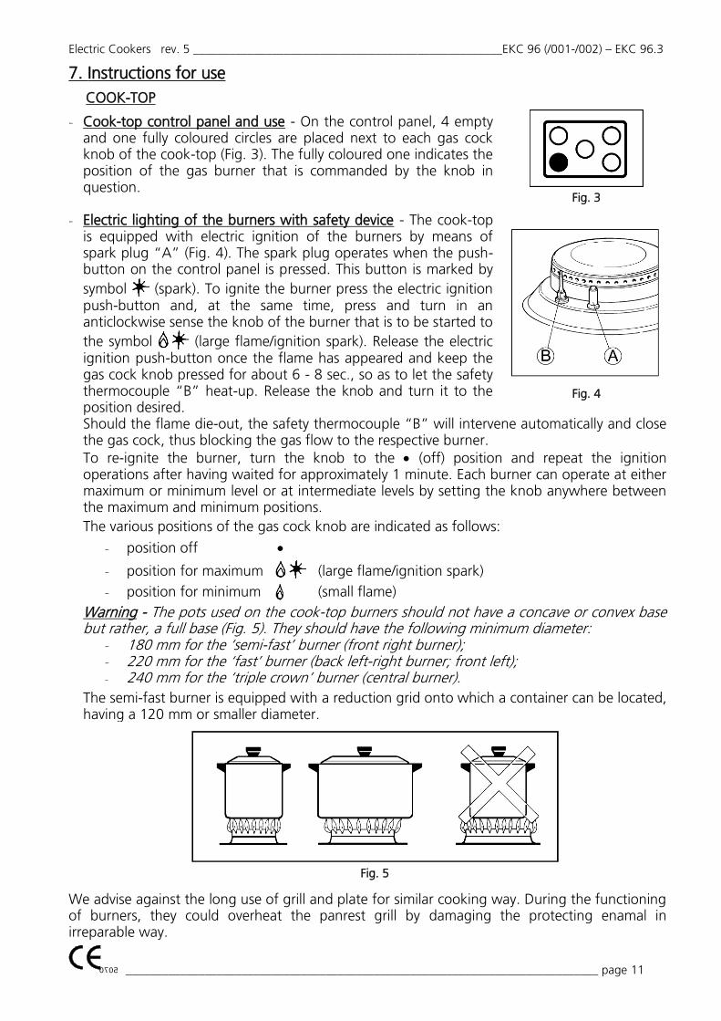
MOD. EKC 96.3
Key
M Power terminal board Pr "End of cooking" programmer C Selector for multifunction IA Push-button switch A A.T. ignition device T1 Safety thermostat T2 Control thermostat MI Door microswitch
L1-L2 Oven lamps S1 Grill indicator light S2 Thermostat indicator light B1 Contactor coil B2-B3 Relay coil V1-V2 Radial motoventilators R1-R2 Circular heating elements R3 Grill heating element
10. Technical assistance and original spare parts
Before leaving the factory, this appliance was tested and set up by expert, specialised personnel, to ensure best operating results. Any eventual assistance or regulation must be done with maximal care and attention, using original spare parts.
For this reason it is necessary to apply to the distributor that has done the sale, specifying the type of inconvenience and model of the appliance purchased. The required parts for different gas type adaptation are available along with the appliance at the moment of sale or delivery.
For any maintenance the user can contact Tecnoeka by calling the telephone numbers on the cover or going to www.tecnoeka.com.
Electric Cookers rev. 5 ___________________________________________________EKC 96 (/001-/002) – EKC 96.3
0705 ______________________________________________________________________________ page 17
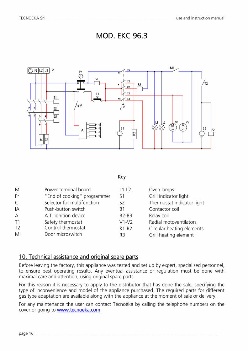
List of spare parts
COMPONENT EKC 96 / EKC 96/001
EKC/002 EKC 96.3
Burner cup semi-fast (1750 W) 00001210 00001210
Burner cup fast (3000 W) 00002080 00002080
Burner cup triple crown (3500 W) 00001300 00001300
Burner flame separator semi-fast (1750 W) 00001220 00001220
Burner flame separator fast (3000 W) 00001940 00001940
Burner flame separator triple crown (3500 W) 00001600 00001600
Burner cover semi-fast (1750 W) 00001230 00001230
Burner cover fast (3000 W) 00001950 00001950
Burner ring cover triple crown (3500 W) 00001900 00001900
Burner central cover triple crown (3500 W) 00001910 00001910
Ignition plug (for 3500 W burner, triple crown) 01200620 01200620
Ignition plug L=650 (for 1750 W and 3000 W burner, semi-fast and fast)
01200600 01200600
Ignition plug L=800 (for 3000 W burner, fast) 01200610 01200610
Power supply cable + Supply terminal board 00002260
00002620 (only for EKC 96/002) -----
Power supply cable 5x2.5 mm2 ----- 00002670
Supply terminal board ----- 01200980
Telecontactor ----- 01201680
Selector for multifunction 01200180 01200180
Spark generator 01200380 01200380
Push-button switch 00008970 00008970
Micro-switch for the door 01201700 01200890
Motor for oven ventilation 01201460 01201460
Lampholder Body 00002330 00002330
Oven programmer 01202980 01202980
Relay ----- 01200820
Circular heating elements 01200390 01201000
Grill heating elements 01200262 01200262
Cock with valve for gas semi-fast burner 00000820 00000820
Cock with valve for gas fast burner 00000780 00000780
Cock with valve for gas triple crown burner 00000810 00000810
Safety thermocouple (for 1750 W and 3000 W burners) 01200590 01200590
Safety thermocouple (for 3500 W burner) 01200580 01200580
Safety thermostat 01200400 01202780
Control thermostat 01201230 01201230

TECNOEKA Srl ______________________________________________________________ use and instruction manual
page 18 ________________________________________________________________________________________
11. Informations to the consumers
Further to Directive 2012/19/UE, the symbol of the crossed rubbish skip on the appliance means that at the end of its life, the product must be disposed of separately from the other rubbish. The user must hand the appliance to a specialised waste collection centre for electric and electronic equipment. The separate collection of the rubbish and subsequent treatment, recovery and disposal help to produce other equipment using recycled materials, reducing the negative effects on the environment and public health, which would be caused by incorrect management of the rubbish. Should the user dispose of the product abusively, administrative sanctions would be applied.
10.Established warranty
Tecnoeka’s products are exclusively designed for food use and are covered by warranty complying with Laws Regulation article n. 1490 and following) for professional users such as VAT holder customers purchasing from Distributor. Tecnoeka’s products are professional and certified according to the IEC 60335-1 standards and can only be sold to professional users. With the exclusion of any additional warranty, the Seller will repair, at its sole discretion, only those parts of its products which prove vitiated by an original defect provided that, subject to revocation, the customer has reported the defect within 12 months from 'purchase and reported the defect within 8 (eight) days of the discovery, in writing enclosing a copy of the invoice, receipt or sales receipt proving the purchase. As well as in the event that the customer is not able to produce the invoice, receipt or sales receipt proving the purchase or are not respected the terms outlined above, the guarantee is expressly excluded in the following cases:
1) Any failure or breakage of components caused by transport. 2) Damage caused by inadequate electrical, plumbing and gas installation than provided in the
installation manual, or by an abnormal function of the same. 3) Damage resulting from incorrect installation of the product, or installation not in accordance
with the requirements in the installation manual, and in particular damage due to failure of the chimneys and the discharges which this product is connected.
4) Product use for purposes other than those it is intended for, as specified and resulting from the technical documentation released by Tecnoeka.
5) Damage caused by use of the Product not in accordance with instructions contained in the user and maintenance manual.
6) Product tampering. 7) Adjustment Operations, maintenance and repair of the product performed by unqualified
personnel. 8) Use of non-original or not authorized parts by Tecnoeka. 9) Damage or defect caused by negligent and / or reckless of the product, or in contrast with the
instructions prescribed by the instruction and maintenance manual. 10) Damage caused by a fire or other natural events and in any case any damage by accident or
addicted to any cause not dependent on the manufacturer. 11) Damage to parts subject to normal wear that need to be replaced periodically.
Also excluded from the guarantee: the painted or enameled parts, knobs, handles, mobile or removable plastic parts, light bulbs, glass parts, seals, electronic parts, and all the possible accessories, transport costs from the based consumer, the end user and / or purchaser to the seat of Tecnoeka Ltd. and vice versa. The warranty doesn't include also the oven's replacement costs and the related installation costs. The warranty excludes products purchased as used or purchased from third parties not connected or authorized by Tecnoeka.

Electric Cookers rev. 5 ___________________________________________________EKC 96 (/001-/002) – EKC 96.3
0705 ______________________________________________________________________________ page 19
TECNOEKA SRL is not responsible for damages, direct or indirect, caused by the product failure, or following to the forced suspension of use of the same. Warranty repairs do not result in the extension or renewal thereof. Parts replaced under warranty are in turn a guarantee of 6 months from the date of shipment, attested by a movement document issued by Tecnoeka. Nobody is authorized to modify the terms and conditions of guarantee or to release other verbal or written.
13. Availability and supply of spare parts
Tecnoeka Srl guarantees the supply of spare parts for a period not exceeding 24 months from the invoice date of the appliance purchased. After that date, availability of spare parts cannot be guaranteed.
14. Applicable laws and court of competent jurisdiction The supply relationships will be regulated by Italian law, with the express exclusion of the international law norms and the Vienna Convention on the International Sales of Movable Assets dated 11 April 1980. Any disputes will fall under the exclusive jurisdiction of the Padua Court.
The products included on manuals may be subject, without any notice or responsibility for Tecnoeka Srl, to technical and functional design changes aiming at improvements without compromising their essential functional and safety features. Tecnoeka Srl is not responsible for any inaccuracies due to bad printing or transcription errors, that could appear on any tool of presentation and/or technical and commercial description of its products to customers.