use and maintenance manual - coffee machine · pdf file3.2 hydraulic connection for epu - evd...
TRANSCRIPT

ENGL
ISH
ESPRESSO COFFEE MACHINEUSE AND MAINTENANCE MANUAL
Instructions for technician
Via Santi, 9 - 40011 ANZOLA EMILIA (BO) - ITALYTel. +39.051.6500900 - Fax +39.051.733701
www.wega.it - [email protected]
R


SUMMARY follows
Summary1. TECHNICAL CHARACTERISTICS ................................................................................................................ 6
LEVER MACHINE .......................................................................................................................................................... ............................6
DISTRIBUTION MACHINE .......................................................................................................................................................... ................6
TECHNICAL CHARACTERISTICS .......................................................................................................................................................... .......7
INTERNAL COMPONENTS ......................................................................................................................................................... ...............8
2. PREPARATION OF THE MACHINE ............................................................................................................ 92.1 UNPACKING ...............................................................................................................................................................9
2.2 EQUIPMENT PREPARATION ......................................................................................................................................9Motor pump .......................................................................................................................................................... ...................................9
Filter-holder .......................................................................................................................................................... ...................................9
Spouts ......................................................................................................................................................... ............................................9
Softener .......................................................................................................................................................... .........................................9
3. MACHINE INSTALLATION ....................................................................................................................... 103.1 POSITIONING ..........................................................................................................................................................10
3.2 HYDRAULIC CONNECTION FOR EPU - EVD - EVDT MACHINES ...............................................................................11
3.3 HYDRAULIC CONNECTION OF ALE MACHINES .........................................................................................................11Warnings ......................................................................................................................................................... ..................................... 11
LEVER MACHINE .......................................................................................................................................................... ......................... 11
3.4 ELECTRICAL CONNECTION ......................................................................................................................................12Machine with INTERNAL MOTOR PUMP ................................................................................................................................................ 12
Machine with EXTERNAL MOTOR PUMP ............................................................................................................................................... 12
3.5 GAS CONNECTION (if provided for) ........................................................................................................................12
3.6 STARTING THE MACHINE .......................................................................................................................................13
3.7 EXTERNAL MOTOR PUMP ADJUSTMENT ................................................................................................................13
4. Distribution machine BOILER and EXCHANGERS .................................................................................. 144.1 ELECTRIC HEATING .................................................................................................................................................14
4.2 GAS HEATING ..........................................................................................................................................................14
4.3 COMBINED GAS + ELECTRIC HEATING ...................................................................................................................14
5. COFFEE DELIVERY GROUPS ................................................................................................................. 145.1 LEVER GROUP ........................................................................................................................................................14
5.2 DELIVERY GROUP ...................................................................................................................................................15
5.3 DELIVERY DELIVERY ...............................................................................................................................................15
6. Automatic Water Entry .......................................................................................................................... 16
7. VOLUMETRIC DOSING ........................................................................................................................... 16
8. PRESSURE SWITCH ............................................................................................................................... 16
9. ANTI-FLOODING DEVICE ....................................................................................................................... 17
10. PUMPING SYSTEM .............................................................................................................................. 17
11. VALVE GROUP .................................................................................................................................... 1711.1 NEGATIVE PRESSURE VALVE ................................................................................................................................17
11.2 SAFETY OR PRESSURE RELIEF VALVE ..................................................................................................................17
11.3 EXPANSION VALVE - NON-RETURN VALVE ...........................................................................................................17
12. GAS SYSTEM ....................................................................................................................................... 18Gas adjustment ......................................................................................................................................................... ........................... 18

SUMMARY follows
13. SOFTENERS ........................................................................................................................................ 19Softener regeneration .......................................................................................................................................................... ................ 19
14. ELECTRONIC CONTROL UNIT .............................................................................................................. 2015.1 EVD PUSH BUTTON PANEL ..................................................................................................................................20
15. ELECTRONIC PUSH BUTTON PANELS ................................................................................................. 2015.2 TH JUNIOR PUSH BUTTON PANEL ........................................................................................................................21
15.3 EVDT TIMER PUSH BUTTON PANEL .....................................................................................................................21
16. DISPENSING HOT WATER .................................................................................................................... 22
17. CAPPUCCINO MAKER .......................................................................................................................... 22
18. CUP HEATING DEVICE ......................................................................................................................... 23
19. CLEANING ........................................................................................................................................... 23Filter and filter-holder ......................................................................................................................................................... ................ 23
Perforated disk and containment ring ................................................................................................................................................. 23
Steam nozzles .......................................................................................................................................................... ............................ 23
Delivery groups (except for ALE version) ............................................................................................................................................ 24
Body .......................................................................................................................................................... ........................................... 24
Grinder-doser .......................................................................................................................................................... ............................. 24
Cappuccinatore ......................................................................................................................................................... ........................... 24
20. CHECKS AND MAINTENANCE .............................................................................................................. 25Machine .......................................................................................................................................................... ...................................... 25Grinder-doser .......................................................................................................................................................... ............................. 25
Softener .......................................................................................................................................................... ...................................... 25
21. MALFUNCTIONS AND CORRESPONDING SOLUTIONS .......................................................................... 26
22. LIST OF HAZARDS ............................................................................................................................. 29
ENCLOSURES
HYDRAULIC DIAGRAMS ............................................................................................................................... IDR
ELECTRICAL DIAGRAMS ............................................................................................................................. ELE
INTERFACE SYSTEMS ................................................................................................................................. ITF
SERVING COUNTER ................................................................................................................................... CNS
MACHINE TECHNICAL DATA SHEETS .........................................................................................................SMCSIBILLA machine ......................................................................................................................................................... ................. SMC-01

ESPRESSO COFFEE MACHINEUSE AND MAINTENANCE MANUAL
Instructions for technician

espresso coffee machine - instructions for technician
6
R
English
1. TECHNICAL CHARACTERISTICS
DISTRIBUTION MACHINE
LEVER MACHINE
14
16
12
132
104
4
1
3
11
87
6
6
15
3
5
9
18
12
3
15
4
1
3
104 11
8
7
6
6
2
14
13
1517 18
5
9
espresso coffee machine - instructions for technicianR
English 7
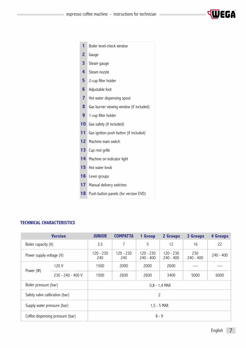
TECHNICAL CHARACTERISTICS
1 Boiler level-check window
2 Gauge
3 Steam gauge
4 Steam nozzle
5 2-cup filter holder
6 Adjustable foot
7 Hot water dispensing spout
8 Gas burner viewing window (if included)
9 1-cup filter holder
10 Gas safety (if included)
11 Gas ignition push button (if included)
12 Machine main switch
13 Cup rest grille
14 Machine on indicator light
15 Hot water knob
16 Lever groups
17 Manual delivery switches
18 Push button panels (for version EVD)
Boiler capacity (lt)
Power supply voltage (V)
Boiler pressure (bar)
Safety valve calibration (bar)
Supply water pressure (bar)
Coffee dispensing pressure (bar)
3,5 5 12 16 22
240 240 - 400 240 - 400 240 - 400120 - 230 120 - 230 120 - 230
2
1,5 - 5 MAX
8 - 9
Version JUNIOR 1 Group 2 Groups 3 Groups 4 Groups
0,8 - 1,4 MAX
240 - 400230
7
240120 - 230
COMPATTA
120 V 1500 2000 2600 ---- ----2000
230 - 240 - 400 V 1500 2600 3400 5000 60002600Power (W)

espresso coffee machine - instructions for technician
8
R
English
INTERNAL COMPONENTS
1 Boiler
2 Delivery group
3 Internal motor pump (if included)
4 Boiler / motor pump pressure gauge
5 Boiler level-check window
6 Internal pump water attachment connection (if included)
7 Manual water pump
8 External pump water attachment connection
9 Drain tub
10 Volumetric dosing device (EVD)
11 Machine main switch
12 Gas system (if included)
13 Electrical heating element
14 Pressure switch
13
4
5
14
9
10
2
11
6
12
13
7
8

espresso coffee machine - instructions for technicianR
English 9
2. PREPARATION OF THE MACHINE
2.1 UNPACKING
Open the packaging, taking care not to damage it. Remove the machine protections and the equipment contained in the package. Take the machine out. If there is an external motor pump, the motor and the pump are provided in separate packaging.
2.2 EQUIPMENT PREPARATION
Motor pumpIn machines with an external motor, it is necessary to prepare the pump and the motor. Fit the 3/8 gas connection with filter (2) at the pump inlet (arrow ) and the plain 3/8 connection (1) at the pump outlet (arrow ).Attention: install the connection with filter (2) at the pump inlet.Use the special washers (3) provided for the seal.To correctly couple the pump and motor, use the appropriate joint (4) and the spacer ring (5). Lock all of this with the two clamps (6).The pump-motor joint is also installed in machines with an internal motor, with the exception of the Junior version and the Zecchin type motors.
Filter-holderIn the housing of the filter holder (7), place the filter clamp spring (8). Take the two-cup (9) or one-cup (10) filter and press it firmly into the filter holder.
SpoutsComplete the filter holder by installing the two-cup (12) or one-cup (13) spout.In Italy provide for an extension cord (11).Attention: install the spout on the relative filter holder: one-cup spout on one-cup filter, etc.
SoftenerThe resin softener is standard equipment on versions EVD-EVDT. It is furnished on request in versions ALE-EPU.For further information, refer to the “Softeners” chapter.
7
8
910
11
1213
2
1
3
45
6
3
6

espresso coffee machine - instructions for technician
10
R
English
3.1 POSITIONING
Prepare an ample support base for the machine that is suitable to support its weight (1). It is important for all terminals of connections to the water mains (2), to the electrical mains (3) and to the gas mains (in included), to be easily reachable and in any case in the immediate vicinity of the machine.Make sure that there is sufficient space for placing and correctly using the appliance. The grinding-dosing machine (4) must be placed in the immediate vicinity of the appliance in order to allow for comfortable use of the machine.It is advisable to equip the working base of the machine with a drawer (5) for used coffee grounds. Preferably this would also have a rubber device to tap the filter holder against.
3. MACHINE INSTALLATION
1
2
3
4
6
7
8
9
10
1112
13
14
15
5
WARNINGFor correct operation, the machine must rest on a perfectly horizontal surface. Any alignment adjustments of the ma-chine must be done by adjusting the feet.(6)
DISTRIBUTION MACHINE
espresso coffee machine - instructions for technicianR
English 11
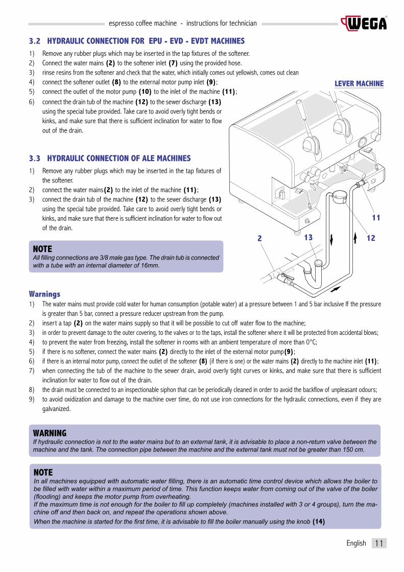
3.2 HYDRAULIC CONNECTION FOR EPU - EVD - EVDT MACHINES1) Remove any rubber plugs which may be inserted in the tap fixtures of the softener.2) Connect the water mains (2) to the softener inlet (7) using the provided hose. 3) rinse resins from the softener and check that the water, which initially comes out yellowish, comes out clean4) connect the softener outlet (8) to the external motor pump inlet (9);5) connect the outlet of the motor pump (10) to the inlet of the machine (11);
WARNINGIf hydraulic connection is not to the water mains but to an external tank, it is advisable to place a non-return valve between the machine and the tank. The connection pipe between the machine and the external tank must not be greater than 150 cm.
NOTEIn all machines equipped with automatic water fi lling, there is an automatic time control device which allows the boiler to be fi lled with water within a maximum period of time. This function keeps water from coming out of the valve of the boiler (fl ooding) and keeps the motor pump from overheating.If the maximum time is not enough for the boiler to fi ll up completely (machines installed with 3 or 4 groups), turn the ma-chine off and then back on, and repeat the operations shown above.When the machine is started for the fi rst time, it is advisable to fi ll the boiler manually using the knob (14)
NOTEAll fi lling connections are 3/8 male gas type. The drain tub is connected with a tube with an internal diameter of 16mm.
6) connect the drain tub of the machine (12) to the sewer discharge (13) using the special tube provided. Take care to avoid overly tight bends or kinks, and make sure that there is sufficient inclination for water to flow out of the drain.
3.3 HYDRAULIC CONNECTION OF ALE MACHINES1) Remove any rubber plugs which may be inserted in the tap fixtures of
the softener.2) connect the water mains(2) to the inlet of the machine (11);3) connect the drain tub of the machine (12) to the sewer discharge (13)
using the special tube provided. Take care to avoid overly tight bends or kinks, and make sure that there is sufficient inclination for water to flow out of the drain.
Warnings1) The water mains must provide cold water for human consumption (potable water) at a pressure between 1 and 5 bar inclusive If the pressure
is greater than 5 bar, connect a pressure reducer upstream from the pump. 2) insert a tap (2) on the water mains supply so that it will be possible to cut off water flow to the machine; 3) in order to prevent damage to the outer covering, to the valves or to the taps, install the softener where it will be protected from accidental blows; 4) to prevent the water from freezing, install the softener in rooms with an ambient temperature of more than 0°C; 5) if there is no softener, connect the water mains (2) directly to the inlet of the external motor pump(9);6) if there is an internal motor pump, connect the outlet of the softener (8) (if there is one) or the water mains (2) directly to the machine inlet (11);7) when connecting the tub of the machine to the sewer drain, avoid overly tight curves or kinks, and make sure that there is sufficient
inclination for water to flow out of the drain.8) the drain must be connected to an inspectionable siphon that can be periodically cleaned in order to avoid the backflow of unpleasant odours;9) to avoid oxidization and damage to the machine over time, do not use iron connections for the hydraulic connections, even if they are
galvanized.
2
11
1213
LEVER MACHINE

espresso coffee machine - instructions for technician
12
R
English
3.5 GAS CONNECTION (if provided for)
Install a pressure reducer upstream from the gas system. When operating on gas, the machine emits combustion fumes directly into the surroundings where it is being used. Therefore, gas-powered machines must not be installed in rooms with a volume of less than 12 m3, as described in standards UNI 7129 and UNI 7131.On the pipe works upstream from the machine, a cut-off cock must be installed. If flexible hoses rather than stiff pipes are used for connections, they must be compliant with standard UNI 7140. These hoses must not be more than one metre long, and they must be firmly attached to the hose connection with a safety clamp (UNI 7141). They must not be placed near potential heat sources, they must not reach a temperature greater than 50°C, they must not be subjected to traction or twisting stress, and they must not have any kinks in them. It must be possible to inspect them along their entire length, and they must not come into contact with sharp objects or sharp corners. The machine is assembled with the methane gas nozzle already installed. The nozzle for city gas or gas cylinders is provided. Check that the nozzle is appropriate to the type of gas being used before lighting the burner. The incoming gas pipe must be equipped with a cut-off cock near the machine (see the provided gas diagram). At the cock outlet there will as necessary be installed a flexible hose or a stiff copper pipe. Pipe connections to the machine must be made in accordance with current standards in the country of installation. If connection is made with a flexible hose, first of all insert the hose into the gas safety hose connection.If instead you would like to make a stiff connection, you can use a soft copper pipe Ø6x8, equipped with a 1/4 gas nipple at the gas safety (remove the hose connection first).
1. Hose connection tube2. Gas ignition push button3. Gas self-regulator4. Gas safety5. Nozzle6. Burner
NOTETo adjust the gas system, refer to chapter12.The water in the boiler can be heated in various ways: only electrically (ma-chines without gas system), only with gas (version ALE), with a combined system of gas and electricity (machines with gas system).
65
3
24
1
WARNINGAlways connect the motor pump cable before the machine power supply cable, in accordance with the diagram provided. Failure to comply with the instructions given above may cause serious damage to the machine an/or to the motor pump and will invalidate any guarantee. Carry out all electrical connections with the power supply disconnected.
3.4 ELECTRICAL CONNECTION
On the electrical mains, it is advisable to install a main protection switch (A)
Machine with INTERNAL MOTOR PUMPConnect the power cable as set forth in the chapter “Electrical diagrams” (the cable has a cross-section and number of wires based on the power and voltage of the machine).
Machine with EXTERNAL MOTOR PUMP1) Connect the cable to the motor pump (with lesser cross section) to the connector
as shown in the diagram shown alongside. 2) Connect the machine power cable (with greater cross section) as set forth in the
chapter “Electrical diagrams”.
CBMGV
BMGV
MP
C Motor pump power cableMP Motor pump terminalB BlueM BrownGV Yellow-green
A

espresso coffee machine - instructions for technicianR
English 13
3.6 STARTING THE MACHINE
Before starting the machine, make sure that the level of water in the boiler is higher than the minimum level on the level-check window (1). If there is no water (first installation or after boiler maintenance), it is necessary to fill the boiler in advance, so as to prevent overheating of the heating element. Proceed as follows:
SwitchOpen the water tap of the water mains and of the softener.Using manual fill (2) fill the boiler with water until the optimal level is restored. Turn the switch to position “1” and wait for the machine to warm up completely.
CommutatorOpen the water tap of the water mains and of the softener.Turn the switch to position “1” (electrical power supplied to the pump for automatic boiler filling and machine services) and wait for the boiler to be automatically filled with water. Turn the switch to position “2” (full electrical power supplied, including the heating element in the boiler) and wait for the machine to warm up completely.
For the installation of the most suitable injector, see the table shown alongside.
WARNINGDo not under any circumstances attempt to light the gas without fi rst installing the proper injector. As soon as con-nection is complete, check for any gas leaks by placing a soapy solution on all connections.
WARNING• during the machine’s warm-up phase (roughly 20 minutes), the negative pressure valve will release steam for a few seconds until the
valve itself closes• before using the machine, run deliveries dry with the filter holder attached for a few seconds to release any air which may be in the
circuit, so that the delivery groups are completely heated• before using the machine, dispense a few servings of coffee to test the grinding and to check the operating pressure of the machine
1 20
3
1 Group ø 1.00 (1.75 kW)
2 Groups ø 1.10 (2.25 kW)
3 Groups ø 1.35 (3.20 kW)
4 Groups ø 1.45 (4.00 kW)
Version METHANE gas(18 mbar)
ø 0.60 (1.50 kW)
ø 0.65 (1.75 kW)
ø 0.80 (2.50 kW)
ø 0.85 (3.00 kW)
LPG(28/37 mbar)
10
1
2
Switch
Commutator
3.7 EXTERNAL MOTOR PUMP ADJUSTMENT
To adjust operating pressure proceed as follows:• Use a coffee delivery switch.• Adjust the pressure by turning the screw located on the pump (3) so as to obtain a pressure
of between 8 and 9 bar. Tightening the screw increases pressure, and loosening it reduces pressure. Check the pressure by means of the gauge(4) located on the front part of the machine;
• turn off the delivery switch; 4

espresso coffee machine - instructions for technician
14
R
English
4. Distribution machine BOILER and EXCHANGERSThe boiler is constructed in copper sheet metal (1), to which the heat exchangers are assembled which in turn are connected to the delivery group. Water for coffee delivery is taken directly from the heat exchanger. During delivery cold water is sent to the inside of the exchanger by means of the motor pump. Inside the heat exchanger, cold water and the pre-existing hot water are mixed, thus obtaining optimal water temperature for coffee infusion. The ALE does not have a heat exchanger, therefore water is taken directly from the boiler.
4.1 ELECTRIC HEATING
5. COFFEE DELIVERY GROUPSThe delivery group and the heat exchanger are the fundamental components in obtaining espresso coffee. Specifically, the purpose of the group is to dispense the coffee.
The water is heated in the boiler by means of an electrical heating element that is immerged in the water(2).
4.2 GAS HEATING
Gas heating is obtained by supplying the flame of the burner located under the boiler.
4.3 COMBINED GAS + ELECTRIC HEATING
In machines equipped with both systems, it is possible to combine the heating types.
5.1 LEVER GROUP
The lever group uses the boiler pressure and water. This system does not require heat exchangers.When the lever (1) is lowered, the spring (2) inside the group is compressed: the piston (3) raises, allowing water to enter the pre-infusion jacket. When the lever is released, the piston compresses the water to 8-10 bar, allowing delivery of espresso coffee. The non-return ball valve (4) keeps water from flowing back into the boiler (5).
2
1
3
245
1
Phase 1Lowering the lever.
Phase 2Pre-infusion for3÷5 seconds.
Phase 3Release of lever
and deliveryof the coffee.

espresso coffee machine - instructions for technicianR
English 15
5.2 DELIVERY GROUP
In this system, the delivery group (1) is heated by a thermosiphon circuit (2) connected to the heat exchanger (3). The same water is used for coffee delivery, thus ensuring the same temperature for all coffee servings. • activation of the solenoid valve and of the pump allow cold water to enter the exchanger (3) through the injector (4).• from the exchanger (3) the boiler water is carried to the group (4) for delivery;• the pump allows the increase of the pressure of the water flow up to 8-9 bar for delivery.
The injector (4) and the flow reducer (5) are important components for the operation of the delivery group.To increase the coffee extraction temperature, remove the flow reducer (5) or replace it with one of a greater diameter. To decrease the temperature, replace it with one of a smaller diameter.If necessary, the exchangers can be replaced by removing the flange and disconnecting the relative pipes of the hydraulic circuit. These ope-rations should be carried out after the machine has been switched down and has cooled off. Always replace the seals.
inletwater
deliverycoffee
in delivery
3
4
5
at rest
1
2
3
5.3 DELIVERY DELIVERY
This group functions with a double-outlet type exchanger.The delivery is controlled with a manual valve system. The opening and the closing of the valves for the passage of the water is operated by a lever placed beside the group which, in turn, operates a cam inside the group, opening and closing the water.

espresso coffee machine - instructions for technician
16
R
English
6. Automatic Water Entry
The AEA system (Automatic Water Entry) is for checking the boiler level. It is composed of:• sensor inserted in the boiler (1), composed of a stainless steel rod;• control unit (2) standard on EVD machines, electronic level regulator on other
versions (3);• hydraulic circuit with a solenoid valve controlled by the regulator.
The electronic control unit controls the level of water in the boiler. When the level of water in the boiler drops, the contact with the probe is interrupted. The control unit sends and impulse to the entry solenoid valve (1) and to the motor pump (2), which act to restore the normal level of water in the boiler.
To avoid possible flooding due to machine malfunctions or leaks in the hydraulic circuit, the electronic control unit includes a timing device that cuts off automatic filling after a certain time (roughly 30 seconds). The LED (4) located on the front of the machine body comes on to indicate activation of this system. During the installation of machines with three or four groups the initial water filling time may exceed the established time limit. In this event, just switch the machine off and then back on to restore normal operating conditions.
7. VOLUMETRIC DOSING
The volumetric dosing device installed on the EVD electronic machines serves the purpose of measuring the quantity of water sent to the group of espresso delivery.The dosing device generates an electrical impulse which is sent to the electronic control unit. This impulse is read by the control unit and memorized during the programming of the dose.The flashing of the LED (5) indicates that the electrical impulse has been sent from the dosing device to the control unit.
8. PRESSURE SWITCH
The pressure switch makes it possible to control boiler pressure by activating or bypassing the heating element in the boiler.Any calibration of the pressure switch which may be required can be carried out with the ma-chine in operation by means of the screw (6) located on the body of the component.
1
2
3
4
5
6
WARNINGAlways check the level of the water in the boiler by means of the level-check window placed on the front of the machine.
WARNINGThe internal contacts of the pressure switch may be subject to oxidization. It is recommended to periodically clean the contacts with anti-oxidant spray.

espresso coffee machine - instructions for technicianR
English 17
11. VALVE GROUP
The valves are devices whose purpose is to ensure the safety and proper operation of the machine.
10. PUMPING SYSTEM
This is a component that serves the purpose of feeding the machine, raising the water pressure to 8-9 bar for the delivery of the coffee and for automatic filling of the boiler.
9. ANTI-FLOODING DEVICE
The cover installed on the pressure modulating switch makes it possible, by means of the special tube, to collect and carry to the drain tub any water which may exit the boiler to due any malfunction of the machine.
11.1 NEGATIVE PRESSURE VALVE
The purpose of the negative pressure valve is to prevent the backflow of liquids through the steam nozzle when they are being heated. Furthermore, the excess air is eliminated inside the boiler during the heating phase of the machine.
11.2 SAFETY OR PRESSURE RELIEF VALVE
The pressure relief valve guarantees that the pressure in the boiler does not go above 2 bar. If there is a malfunction, the capacity of the valve is such that it can eliminate all of the excess pressure in the valve.
11.3 EXPANSION VALVE - NON-RETURN VALVE
This is a valve consisting of an expansion valve and a non-return valve.• Expansion valve: the cold water sent from the pump to the heat exchangers
is heated. This heating causes an increase in the volume of water. To limit increases of pressure in the hydraulic circuit, the valve limits the maximum internal pressure of the circuit to 12 bar.
• non-return valve: Its function is that of preventing the back flow of water from the exchangers in the hydraulic circuit.
NOTEOn all machines with four groups, two pressure relief valves are installed.
valveEXPANSION
valveNON-RETURN

espresso coffee machine - instructions for technician
18
R
English
12. GAS SYSTEM
The gas system is useful in heating the water in the boiler. It does not, except in special cases, substitute the electrical heating system, but rather works along with it. For machines with levers, operation may be either electric or gas.
Gas adjustment• Lighting the burner • loosen the locknut (1);• give the screw two turns and place the minimum regulator pin (2) so as to have maximum opening of the gas minimum passage;• wait for boiler pressure to reach 1.4 bar (see boiler gauge);• turn the minimum pin (2) clockwise until the burner flame is barely visible (pilot flame);• lower the pressure in the boiler down to 1 bar;• turn the adjustment screw for the maximum clockwise until the flame is up to maximum;• tighten the locknut thus locking the screw.
The operation described above places the machine in an operating range of 1.2-1.3 bar. If you want to increase or decrease operating pressure in the boiler, proceed as above, varying the parameters as follows:to decrease:• set the maximum to 1.3 bar and the minimum to 0.9 bar. You will obtain pressure in the boiler of 1.1-1.2 bar.to increase:• adjust the maximum to 1.5 bar and the minimum to 1.1 bar. You will obtain a pressure in the boiler of 1.3-1.4 bar (this is the maximum recommended pressure limit)
1
2
WARNINGIf you decide to use only the gas heating system, no electrical devices are active, including automatic boiler fi lling.
WARNINGWhen operating on gas, the machine emits combustion fumes directly into the surroundings where it is being used. The-refore, gas-powered machines must not be installed in rooms with a volume of less than 12 m3, as described in standards UNI 7129 and UNI 7131.In closed rooms, always provide ventilation openings to release any possible gas leaks.

espresso coffee machine - instructions for technicianR
English 19
13. SOFTENERS Mains water contains insoluble salts, which cause the build-up of lime scale deposits in the boiler and in other parts of the machine. The softener makes it possible to eliminate or substantially reduce the presence of these mineral salts.
The resin softener has the property of retaining the calcium contained in the water. For this reason after a certain period the resins are saturated and are to be regenerated with coarse kitchen salt (NaCL, sodium chloride) or special water softening salt. It is very important to regenerate the softener within the established times. The regeneration is to be done regularly every 15 days. However, in locations with very hard water, it will be necessary to regenerate more frequently. The same is true of places in which there is a large consumption of hot water for tea or other uses.
Softener regenerationProceed as follows:• move levers (2) and (5) from left to right;• Remove the lid by loosening the knob (1).• Release enough water through the pipe (3) to make room for the amount of salt as required depending on the model (see table). • Clean any salt or resin residue from the gasket located on the lid.• Put the lid back in place by screwing the knob (1) down securely and move the lever (2) back from right to left.• Let the salt water drain from the small tube (4) until the water is no longer salty (about 30-60 minutes). The salt allows the accumulated
mineral salts to be released.• Bring the lever (5) from right to left back to its initial position.
12
3
4
5
In order to keep the softener and hence the machine in perfect operating condition, it is necessary to perform regeneration periodically based on the use of the softener and the hardness of the water that is used. The table alongside shows the values of the quantity of softened water based on the hardness of the water in the various units of measure:- F°: French degree- D°: German degree- mg CaCO3
For further information on installation, start-up and regeneration of the softener, refer to the relative instruction manual.
WARNINGThe build-up of lime scale in the hydraulic circuit and boiler inhibit thermal exchange, thus compromising proper operation of the machine. Heavy incrustation in the boiler may cause long machine shutdowns and in any case invalidate any gua-rantee, because this symptom indicates that regeneration has been neglected.
8 litres 1.0 kg
12 litres 1.5 kg
16 litres 2.0 kg
Modelsoftener
Amountof salt
F° 30°
D° 16.5°
mg CaCO3 300
8 litres 1000 lt
Amount of softened water based on hardness
40°
22°
400
900 lt
60°
33°
600
700 lt
80°
44°
800
500 lt 1.0 kg
salt
12 litres 1500 lt 1350 lt 1050 lt 750 lt 1.5 kg
16 litres 2100 lt 1800 lt 1400 lt 1000 lt 2.0 kg

espresso coffee machine - instructions for technician
20
R
English
14. ELECTRONIC CONTROL UNIT
The electronic control unit is installed on machines with volumetric dosing. Its pur-pose is to control the dose of coffee electronically by means of the water flowing through the dosing device and to check filling of the water entry in the boiler. This control unit is set up to be connected to the delivery accounting systems by means of a specific interface device.
15.1 EVD PUSH BUTTON PANEL
The push button panel is connected to the control unit which allows selection and pro-gramming of the doses of coffee. Programming is carried out in the following way: • Place the programming lever (1) in the ON position. It is located under the front
right-hand panel of the body;• put the coffee cup under the dispensing spout.• press the PROG/STOP key (2) and all dose key LED will come on;• press the desired dose key (3);• when the desired dose has been attained, confirm by pressing the PROG/STOP key (2);• Repeat this operation for the other dose keys.• upon completion of programming, place the programming lever (1) back in the OFF
position. 1
In some models, the programming lever has been eliminated because to access program, and it is enough to press the PROG/STOP key for at least 5 seconds with all push button panel LED coming on. Also, confirmation of the dose can be given by pressing either the PROG/STOP key or the selected dose key.In other models to access programming it is necessary to use a special key switch. To exit programming it is sufficient to wait a few seconds.
NOTEThe programming of every dose must be done with ground coffee and not with previously used grounds.With machines having two or three groups, by fi rst programming the right-hand push buttons the others are automatically programmed. It is however both possible and advisable to program the push button panels independently, always starting from the right-hand push button panel.
15. ELECTRONIC PUSH BUTTON PANELS
3
2
3
2
STOPPROG
3
2

espresso coffee machine - instructions for technicianR
English 21
15.2 TH JUNIOR PUSH BUTTON PANEL
This push button panel is installed mainly on JUNIOR models and on some EVD volumetric dosing machines.Programming is carried out in the following way: • put the coffee cup under the dispensing spout.• Press the PROG/STOP key (1) for at least 5 seconds until all dose key LED are on.• Press the desired dose key (2).• To confirm the dose press the dose key (2) or the PROG/STOP key again (1).• Repeat this operation for the other dose keys.• Programming will be terminated automatically after a few seconds.
15.3 EVDT TIMER PUSH BUTTON PANEL
The timer is installed on EVDT machines and controls delivery time of the coffee.Programming is carried out in the following way:
1) Press and hold down the STOP/PROG key (1) for 5 seconds and check that all of the LED on the push button panel come on. This confirms correct entry into the programming phase.
2) Press on of the two dose keys (2) to program. The LED corresponding to the CONT key (continue) and to the key of the dose being programmed stay on.
3) When the desired amount of coffee in the cup has been reached, press the STOP/PROG key (1) or the key of the dose being programmed to stop delivery and memorize the new value (the duration of the dose of coffee is calculated in seconds). At the same time, the LED for the dose which is still to be programmed comes back on, while the LED for the programmed dose stays off.
4) Proceed with the programming of the other coffee dose by pressing the other dose key. Once the desired amount of coffee in the cup has been reached, press the dose key or the STOP/PROG again (1).
5) To exit programming, press and hold down the STOP/PROG (1) key for more than 5 seconds.
NOTEIt is possible to re-program the coffee dose that you have just fi nished programming (LED off) without necessarily having to turn the system off and back on or exiting the programming phase.The system automatically exits programming status approximately 10 seconds after the last operation.
1
2
1
2

espresso coffee machine - instructions for technician
22
R
English
Programming
• Place the programming lever in the ON position (1) it is located under the front right panel of the body;
• put the cup under the hot water nozzle (2);• press the PROG/STOP key (3) and all dose key LED will come on;• press the key to dispense hot water (4);• when the desired dose has been attained, confirm by pressing the PROG/STOP
key (3);• upon completion of programming, place the programming lever (1) back in
the OFF position
33
2
1 4
1
WARNINGBe sure to keep the cappuccino maker clean at all times as described in the chapter “Cleaning”.
• Put the suction tube in the milk;• place the pitcher under the spout of the cappuccino maker;• turn the steam tap counter-clockwise. When the desired level is reached, close the steam tap;• pour the foamed milk into the cups with the coffee.
NOTETo obtain warm milk without foam, lift the tab (1) upwards. For best results, we recommend not dispensing directly into the coffee cup, but rather into a pitcher. From there, pour the foamed milk into the coffee.
1
CAPPUCCINO position WARM MILK position
16. DISPENSING HOT WATER
17. CAPPUCCINO MAKER

espresso coffee machine - instructions for technicianR
English 23
19. CLEANINGFor perfect cleaning and efficiency of the appliance, several simple cleaning operations are necessary on the functional parts and accessories as well as the body panels.The indications given here are applicable for normal use of the coffee machine. If the machine is heavily used then cleaning should be per-formed more frequently.
Filter and filter-holder The filters and the relative filter-holders must be cleaned daily in hot water. The best thing to do is to let them soak in hot water overnight so that the fatty coffee deposits can dissolve.It is advisable to add an envelope or tablet of special detergent to the water, and then to rinse everything off with water. Failure to clean the filters and filter holders daily will compromise the quality of the coffee and will also cause problems such as bad extraction and coffee grounds at the bottom of the cup.
Perforated disk and containment ringBoth the shower plate (4) and its containment ring (3) should be cleaned weekly in hot water. To do this loosen the screw (5) and remove the two elements from the dispensing unit.
Steam nozzlesThe steam pipes must be kept clean at all times. Check the ends of the steam nozzles and clean them monthly, clearing out the exit holes with a small needle.
1
2
18. CUP HEATING DEVICE
The cup heating device is for heating cups before they are used.• Place the cups on the upper surface (1) of the coffee machine.• Start the electric heating element with the switch (2) or with the push
button panel (e.g. VENUS).
WARNINGFor safety reasons we advise against putting cloths or other objects on the upper surface of the machine as they could obstruct normal air circulation.

espresso coffee machine - instructions for technician
24
R
English
Delivery groups (except for ALE version)The cleaning of the internal parts of the delivery groups is to be performed weekly in the following manner:• replace the normal filter of the filter-holder with a solid one;• pour a teaspoon of a suitable detergent powder on the solid filter, and attach the filter-holder
to the group;• use the delivery switch to set the group in operation;• repeat the above operations until the water comes out clean;• turn off and remove the filter-holder from the group;• rinse a final time, so as to remove any residual detergent.
WARNINGDo not use a solid fi lter to clean the machines with a lever group (ALE)
BodyThe body panels should be cleaned with a cloth soaked in warm water. Do not use abrasive detergents since the panels could get scratched.
Grinder-doserEvery week clean the bell jar and the dosing device with a cloth soaked in lukewarm water, both inside and out.
45
3
Cappuccinatore
Si raccomanda una particolare cura nella pulizia del cappuccinatore seguendo le modalità qui riportate:• eseguire un primo lavaggio immergendo il tubo di aspirazione in acqua ed
effettuare una erogazione per qualche secondo;• ruotare il corpo rotante (1) di 90° in pos. B (chiusura del condotto di
fuoriuscita del latte);• tenendo il tubo di aspirazione latte in aria, effettuare l’erogazione di vapore
(funzionamento a vuoto del cappuccinatore);• attendere circa 20 secondi in modo da permettere la pulizia e sterilizzazione
interna del cappuccinatore;• chiudere il vapore e riportare il corpo rotante in pos. A;• nel caso di ostruzione del foro di prelievo dell’aria (2), liberatelo delicata-
mente con uno spillo.
ATTENZIONESi consiglia di effettuare la pulizia del cappuccinatore dopo ogni uso continuativo in modo da evitare anomalie di funzionamento e garantire un elevato grado di igienità del sistema.
21
pos. A
pos. B

espresso coffee machine - instructions for technicianR
English 25
negative pressure valve - Turn the machine off; - by means of the steam valves, release all pressure in the boiler; - turn the machine back on and check closure of the valve.
pressure limiting valve - Lock the pressure switch contacts. - wait for pressure in the boiler to rise and check for intervention of the valve at a maximum pressure of 2 bar.
Non-return drain valve - Activate the delivery groups for about 30 seconds; - attach a filter holder (5) with a gauge (available on request) to the delivery group; - activate the delivery group, and use the gauge (6) to monitor pressure increase up to 8-9 bar; - check the increase of pressure due to the expansion of the heated water up to a value of approximately 12 bar: reaching this value confirms proper operation of the valve and the seal of the gaskets and solenoid valves; - de-activate the deliveries; - repeat the control on the other delivery groups.
• Periodically check water pressure during coffee delivery. Check the pressure indicated on the gauge, which must be between 8 and 9 bar inclusive.
• Monitor the boiler pressure value as explained in chapter 1, “Technical characteristics”.• Periodically check the condition of the filters. Check for any damage on the edge of the filters and check whether any coffee grounds
settle in the coffee cup. • At least once a year, check for proper operation of the gauge and pressure switch;• At least once a year check for lime scale deposits on the heating element, on the exchanger (inside and out) and on the hydraulic circuit.
When replacing any components, always replace the relative gasket as well. • At least once a year, check the condition of the solenoid valve of the delivery group. • At least once a year check for trace water leaks on the counter. Also check the condition of the discharge tub and its connection to the
sewer system.
Grinder-doser Periodically check the dose of ground coffee (inclusive between 6 and 7 gr. per stroke) and check the degree of grinding. The grinders must always have sharp cutting edges. Their deterioration is indicated by the presence of too much powder in the grounds. It is advisable to replace the grinders after every 400/500 kg of coffee.
SoftenerThe build-up of lime scale deposits in the hydraulic circuit of the machine indicates that regeneration has been neglected. Carry out mainte-nance of the boiler and of the hydraulic circuit, replacing any components as required. Use care in areas where the water is very hard. It will be necessary to regenerate at more frequent intervals; likewise if there is high con-sumption of hot water for tea and so forth.
20. CHECKS AND MAINTENANCE
To ensure perfect safety and efficiency of the machine over time, it is necessary to carry out routine, preventive and special maintenance. In particular, it is advisable to carry out an overall check of the machine at least once a year.
Machine• Carry out cleaning as described in the previous chapter on a daily basis. • Every four months replace the perforated disk (2) and the undercup seal (4) of the delivery group
(use only original spare parts) proceeding as follows: - loosen the screw (1); - remove the containment ring(3); - replace the group perforated disk(2) and the rubber undercup seal (4); - put the components back in place.• At least once a year, check for proper operation of the negative pressure valve, pressure limiting valve
and non-return drain valve. In the event of malfunction they must be replaced. For the checks, proceed as follows:
5
6
21
3
4

espresso coffee machine - instructions for technician
26
R
English
21. MALFUNCTIONS AND CORRESPONDING SOLUTIONSIndication Cause Solution
NO POWERTO MACHINE
1) The machine commutator is in position “0” or “1”2) The machine switch is defective3) The mains power supply switch is in the OFF position 4) The connection to the electrical mains is defective
1) Replace the solenoid valve of the automatic level device 2) Replace the heat exchanger3) Check the level probe, the earth of the frame and the operation of the electronic control unit
NO WATERIN BOILER
1) The water mains tap is closed2) The cut-off tap of the automatic level device is in the closed position3) The pump filter is closed4) The motor pump is disconnected or blocked5) The water filling solenoid is defective6) The water inlet solenoid valve filter is clogged
1) Open the water mains tap2) Open the automatic level device tap
3) Replace the pump filter4) Check the motor pump5) Replace the water filling solenoid valve6) Clean or replace the filter of the solenoid valve
EXCESSIVE WATERIN BOILER
1) The solenoid of the automatic level device is defective2) The heat exchanger is perforated3) The manual valve remains inserted
1) Turn the machine commutator to position “2”2) Replace the main switch3) Place the mains switch in the ON position 4) Check for any defective connections
STEAM DOES NOT COMEOUT OF NOZZLES
1) The electrical heating element is defective2) The pressure switch contacts are oxidized3) The heating element protection thermostat has cut in4) The nozzle sprayer is clogged5) Machine switch in position “1”
1) Replace the electrical heating element2) Clean the contacts or replace the pressure switch3) Reset the heating element protection4) Clean the steam nozzle sprayer5) Turn the machine switch to position “2”
STEAM MIXED WITH WATERCOMES OUT OFTHE NOZZLES
1)The boiler level is too high 1) Check the status of the level probe: verify correct position and check for presence of any surface lime scale
NO DELIVERY
1) No water mains2) Group solenoid valve is defective3) The pump is blocked4) The control unit fuse is burned out 5) The injector is clogged6) The group solenoid valve is clogged or dirty7) The group filter is clogged 8) The volumetric dosing device is blocked
1) Check that there is water in the mains2) Replace the group solenoid valve3) Replace the pump4) Replace the solenoid valve protection fuse (1A)5) Clean or replace the injector6) Clean or replace the solenoid valve7) Clean or replace the filter 8) Check/replace the dosing device
WATER LEAKSFROM THE MACHINE
1) The tub does not drain2) The drain tube is detached or broken or has obstruction to water flow3) Hydraulic leaks in the hydraulic circuit
1) Check the sewer drain2) Check and restore the connection of the drain tube to the tub3) Identify and eliminate hydraulic leaks
COFFEE IS TOO COLD
1) The electrical heating element is defective2) The electrical connection is defective3) Lime scale on the exchangers and/or heating element 4) The pressure switch contacts are oxidized5) The heating element protection thermostat has cut in6) Machine switch in position “1”7) The lime scale has reduced the circulation of water 8) The delivery group is cold
1) Replace the electrical heating element2) Check for any defective connections3) Clean the machine4) Clean the contacts or replace the pressure switch5) Reset the heating element protection6) Turn the machine switch to position “2”7) Clean the connections of the exchanger, and clean or replace the two circulation tubes8) Eliminate air pockets in the hydraulic circuit in the following manner: - disconnect the electrical power supply to the pump- close the water tap of the softener- perform a dry run of delivery for a few minutes- reconnect the electrical power supply to the pump- open the water outlet tap of the softener- perform delivery until water comes out- wait a few minutes for heating

espresso coffee machine - instructions for technicianR
English 27
COFFEE ISTOO HOT
Indication Cause Solution
1) Boiler temperature is too high2) The flow reducer of the group is not suitable
1) Reduce pressure in the boiler by turning the appropriate screw on the pressure switch2) Replace the injector with one of a smaller diameter
DELIVERYOF COFFEEIS TOO FAST
1) The coffee is ground too coarsely2) The diameter of the injector is too large3) Boiler temperature is too high
1) Adjust the grinding of the coffee2) Replace the injector with one of a smaller diameter3) Reduce pressure in boiler
1) Coffee is ground too finely2) The injector is clogged3) The delivery group is clogged4) The filter holder is dirty
1) Adjust the grinding of the coffee2) Replace the injector3) Check and clean the delivery group4) Clean and if necessary replace the filters
COFFEE GROUNDS AREWET
1) The group solenoid valve discharge is clogged2) The delivery group is too cold3) Coffee is ground too finely
1) Clean the group drain2) Wait for group to heat up completely3) Adjust the grinding of the coffee
GROUNDSIN CUP
1) The gauge is defective2) Incorrect pressure switch calibration.3) Incorrect motor pump calibration.
1) Replace the gauge2) Adjust the calibration of the pressure switch3) Adjust the calibration of the motor pump
THE GAUGE SHOWS AN UNACCEPTABLEPRESSURE
1) The filter holder is dirty 2) The filter holes are worn3) The coffee is not ground evenly4) The undercup seal is worn5) The temperature of the delivery water is high
1) Clean the filter holder2) Replace the filter3) Replace the grinders4) Change the seal5) Check the causes and eliminate the problem
for EVD:
COFFEE DELIVERY ONLY BY MEANS OFMANUAL KEY
1) The control unit fuse is burned out2) The coil of the solenoid valve does not work correctly or has shorted out
1) Check for proper connection of the volumetric dosing device connector2) Check for proper connection of the 8-pole connector of the electronic control unit3) Remove the connector of the volumetric dosing device and thoroughly dry the contacts4) Replace the heads of the volumetric dosing device or replace the dosing device5) Adjust the grinding suitably and if necessary check the grinders6) Check and if necessary replace the non-return valve7) Check and if necessary replace the drain valves8) Clean and if necessary replace the solenoid valve9) Clean or replace the volumetric dosing device
for EVD:
INCORRECTCOFFEE DELIVERY
THE COFFEE DOSE IS NOTMET
THE LED OF THEDOSE PUSH BUTTONFLASHES
1) The connection of the volumetric dosing device is defective2) The connection of the electronic control unit is defective3) The connector of the volumetric dosing device has humidity on it4) The volumetric dosing device is defective: during delivery the dosing device LED does not flash5) The coffee is ground too finely: there is not sufficient water flow in the dosing device 6) The non-return valve loses pressures (the dose is too small)7) The drain valves lose pressure (the dose is too small)8) Water leakage from the group solenoid valve during coffee delivery or when at rest9) The volumetric dosing device is partially obstructed
for EVD:ALL THE LED OF ALL THE PUSH BUTTON PANELSFLASH
for EPU-EVDT:THE FRONT LEDFLASHES
After a few minutes, automatic filling with water is stopped:1) Time control device has cut in2) No water in mains3) The tap for the automatic level device is closed4) Some of the tubes in the circuit are clogged5) The probe and/or the earth are disconnected
1) Turn the machine off and then back on2) Open the water mains tap3) Open the automatic level device tap 4) Check and replace the defective tubes5) Check and restore connections
1) Replace the control unit fuse (1A)2) Replace the coil of the solenoid valve
DELIVERYOF COFFEETOO SLOW

espresso coffee machine - instructions for technician
28
R
English
THE PUMP WORKS ONLY WITH THE MANUAL DELI-VERY KEY
Indication Cause Solution
1) The pump fuse of the electronic control unit is burned out
1) Replace pump fuse of the electronic control unit (10 A)
SHUTDOWN OF ELECTRONICSYSTEM
1) The control unit fuse is burned out2) The volumetric dosing device has a contact of the positive pole to the earth
1) Replace the main fuse (125 mA)2) Check for proper connection of the volumetric dosing device
THE PUMPLEAKS WATER
1) Poor mechanical seal of the shaft or of the O-ring2) The inlet and outlet connections are loose3) The hex nut of the pressure relief valve or of the filter are loose4) The gasket or the O-ring of the pressure relief valve or of the filter are defective.
1) Check the status of the pump and take any corrective action which may be required2) Tighten the connections3) Tighten the hex connection of the modulating valve and of the filter4) Replace the gasket and the O-ring. Take care not to change the calibration of the valve
THE PUMP FUNCTIONS BELOW THE NOMINAL CAPACITY
1) The inlet is clogged, perhaps only partially2) The pump rotates in the wrong direction.3) The pressure relief valve is not properly calibrated 4) The motor runs at low RPM5) The inside of the pump is damaged due to the infiltration of foreign bodies
1) Clean the filter holder2) Check the motor3) Calibrate the pressure relief valve4) Check the voltage or replace the motor 5) Replace the pump
1) The pump and the engine are not aligned.2) The gasket or the O-ring of the pressure relief valve or of the filter are defective.3) The joint, the coupling screw or the V-shaped clamp are loose.4) The inlet is clogged, perhaps only partially5) The hex nut of the pressure relief valve or of the filter is loose
1) Install the pump-motor joint2) Replace the gasket and the O-ring. Take care not to change the calibration of the valve3) Align and tighten the components which are loose4) Clean the filter holder5) Tighten the hex connection of the pressure relief valve and of the filter
THE MOTOR STOPSSUDDENLY OR THE THERMAL PROTECTION CUTS IN DUE TO AN OVERLOAD
1) Lime scale and mineral build-ups in the pump have caused it to jam2) The pump and the engine are not aligned.3) The motor is defective4) The motor is connected with a voltage that is not correct
1) Check the status of the pump and if necessary replace it2) Install the pump-motor joint3) Replace the motor4) Ascertain that the power supply voltage of the motor is the right one
THE PUMPIS NOISY
1) Steam pockets in the delivery system2) Air pockets in the hydraulic circuit3) Coffee is ground too finely4) The flow reducer of the group is not suitable
1) Reduce water temperature2) Check the cause and eliminate the problem3) Adjust the grinding suitably4) Replace the flow reducer
THE CUP ISDIRTIED BY SPLASHES OF COFFEE

espresso coffee machine - instructions for technicianR
English 29
22. LIST OF HAZARDSThis chapter describes possible hazards for the user if the specific safety standards described in this booklet are not adhered to.
The appliance must be connected to an efficient grounding systemIf this is not done, the appliance can be a source of dangerous electrical discharges in that it is no longer able to discharge electricty to earth.
Do not use running water to washThe use of pressurized water directly on the machine can seriously damage electrical appliances. Never use water jets to wash any part of the appliance.
Be careful with the steam nozzles and hot waterDuring use, the steam nozzles and hot water may overheat, thus becoming a source of danger. Handle such parts carefully. Never direct steam or hot water jets directly on parts of the body.
Do not intervene on the machine when it is supplied with electrical power.Before carrying out any intervention on the machine you must turn it off by means of the main network switch or better yet, disconnecting the connection terminals in the network. Never remove any body panel when the machine is supplied with electrical power.
Never work on the hydraulic system before having emptied it.All work regarding the hydraulic system and the relative boiler are to be avoided when there is still water and pressure in the system. You must therefore empty it beforehand, closing the mains cock and dry-running the delivery group for a short time. Switch off the machine and open all the steam and water cocks and taps. With the pressure zero, completely empty the boiler, unscrewing the special pipe fitting situated on the lower part of it.If the above procedure is not correctly carried out, opening any part of the hydraulic system can cause a sudden outlet of overheated water under pressure.
Lever machinesNever lower the lever if there is no coffee in the filter, or if the filter holder is not installed on the group: the sudden upwards movement of the lever may damage the appliance and injure individuals.
Gas machinesPeriodically check for gas leaks in the system by applying a soapy solution to the ducts.For safety reasons, close the gas heating system when the machine is not in use (at night or during hours of closure)
Use of the applianceThis espresso coffee machine is an appliance exclusively for professional use. Any other type of use is considered wrong and therefore dan-gerous. Never allow children or incapable persons to use the machine.
Non-observance of the above-described standards can cause serious damage to people or animals.
Never work on the electronic apparatus when the machine is still supplied with electrical energy.
Shut down the machine completely by unplugging it from the mains before carrying out any operation.
WARNINGAny action taken by a technician on the electronics of the machine when the machine is still supplied with electrical power automatically invalidates any guarantee. The technician needs to be aware that the machine is electrically connected and act accordingly.


HYDRAULIC DIAGRAMS
ENGL
ISH
ESPRESSO COFFEE MACHINEUSE AND MAINTENANCE MANUAL
Instructions for the user
Via Santi, 9 - 40011 ANZOLA EMILIA (BO) - ITALYTel. +39.051.6500900 - Fax +39.051.733701
www.wega.it - [email protected]
R


Summary
1. LEVER GROUP hydraulic diagram .......................................................................................................... 5
2. EPU - LEVETTA hydraulic diagramEPU - LEVETTA hydraulic diagramEPU - LEVETTA ......................................................................................................... 6
3. EVD hydraulic diagram ........................................................................................................................... 7


espresso coffee machine - hydraulic diagramsR
IDR 5English
1. LEVER GROUP hydraulic diagram
6
5
12
8
10
7
S2
E
4 1
14
6
3
9
11
13
11
14
15
1 Manual water inlet tap 2 Drain tub 3 Gauge 4 Boiler level-check window 5 Boiler 6 Delivery group 7 Hot water tap 8 Steam tap 9 Safety valve10 Negative pressure valve11 Tap12 Pressure switch13 Automatic Water Inlet Solenoid Valve (optional)14 Water inlet filter15 Boiler heating element E Water inlet S Drain
espresso coffee machine - hydraulic diagrams
IDR 6
R
English
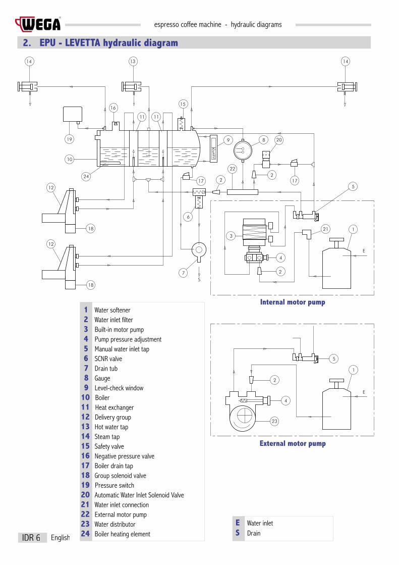
2. EPU - LEVETTA hydraulic diagram
14
10
16
14
19
11
S
3
4
2
22
17
21
8
5
1
E
1
5
4
2
23
E
13
172
20
24
7
6
9
2
15
11
18
12
18
12
External motor pump
Internal motor pump
E Water inlet S Drain
1 Water softener 2 Water inlet filter 3 Built-in motor pump 4 Pump pressure adjustment 5 Manual water inlet tap 6 SCNR valve 7 Drain tub 8 Gauge 9 Level-check window 10 Boiler11 Heat exchanger12 Delivery group13 Hot water tap14 Steam tap15 Safety valve16 Negative pressure valve17 Boiler drain tap18 Group solenoid valve19 Pressure switch20 Automatic Water Inlet Solenoid Valve21 Water inlet connection 22 External motor pump 23 Water distributor 24 Boiler heating element

espresso coffee machine - hydraulic diagramsR
IDR 7English
3. EVD hydraulic diagram14
10
16
14
19
11
S
3
4
2
22
17
21
8
5
1
E
1
5
4
2
23
E
13
172
20
24
7
6
9
2
15
11
18
12
18
22
12
External motor pump
Internal motor pump 1 Water softener 2 Water inlet filter 3 Built-in motor pump 4 Pump pressure adjustment 5 Manual water entry tap 6 SCNR valve 7 Drain tub 8 Gauge 9 Level-check window 10 Boiler11 Heat exchanger12 Delivery group13 Hot water tap14 Steam tap15 Safety valve16 Negative pressure valve17 Boiler drain tap18 Group solenoid valve19 Pressure switch20 Automatic Water Inlet solenoid valve21 Water inlet connection 22 Volumetric dosing device23 External motor pump24 Water distributor25 Boiler heating element
E Water inlet S Drain


ELECTRICAL DIAGRAMS
ENGL
ISH
ESPRESSO COFFEE MACHINEUSE AND MAINTENANCE MANUAL
Instructions for the user
Via Santi, 9 - 40011 ANZOLA EMILIA (BO) - ITALYTel. +39.051.6500900 - Fax +39.051.733701
www.wega.it - [email protected]
R


Summary
1. Electrical diagram ELECTRICAL MAINS CONNECTION ................................................................................ 4
2. Electrical diagram MACHINE POWER SUPPLY ............................................................................................. 5
3. Electrical diagram version ALE with automatic water inlet ....................................................................... 6
4. Electrical diagram version EPU ................................................................................................................. 7
5. Electrical diagram version EVDT ................................................................................................................ 8
6. Electrical diagrams version EVD ................................................................................................................ 9
6.01 Electrical diagram code WY18077-WY18078-WY18079 *GIEMME* ........................................................................10
6.02 Electrical diagram code WY18077-WY18078-WY18079 *GICAR* ...........................................................................11
6.04 Electrical diagram code WY18362-WY18363-WY18365-WY18366 .........................................................................13
6.05 Electrical diagram code WY18090016-WY18090017 ..............................................................................................14
6.06 Electrical diagram code WY18090016-WY18090017 ..............................................................................................15
6.07 Electrical diagram code WY18090030-WY18090031 *GIEMME* .............................................................................16
6.08 Electrical diagram code WY18090030-WY18090031 *GICAR* ...............................................................................17
6.11 Electrical diagram code WY18090047-48 *POLARIS-VENUS* PLUS 1 rev.0 .........................................................18
6.13 Electrical diagram code WY18090037-38 *POLARIS-VENUS* PLUS 2 rev.0 ..........................................................19
6.13.1 Electrical diagram code WY18090037-38-47-48 *POLARIS-VENUS* PLUS 1-2 rev.1 .........................................20
6.14 Electrical diagram code WY18090051-52 *POLARIS* PLUS 3 rev.0 .........................................................................22
6.22 Electrical diagram code WY18090012-13-14-15 *SPHERA* .................................................................................24
6.24 Electrical diagram code WY18090018 - WY18090019 *SPHERA DISPLAY* ..........................................................25

espresso coffee machine - electrical diagrams
ELE 4
R
English
R Phase S Phase T Phase N Neutral
1. Electrical diagram ELECTRICAL MAINS CONNECTION
3-conductor cable
4-conductor cable
3-conductor cable + Neutral + Earth
single phase 120-230-240V
single phase 120-230-240V three phase 230-240V
single phase 120-230-240V three phase 230-240V three phase 400V
BL BlueC Machine cableGV Yellow-greenGR GreyMA BrownNE Black
RN
MA BL GV
C
C
NE BL GV
NR
MA GR
C
MA NE GR BL GV
RN
C
MA GVNE BL
C
SR
MA NE BL GV
T
C
MA NE BLGR GV
ST
RSTN
R

espresso coffee machine - electrical diagramsR
ELE 5English
2. Electrical diagram MACHINE POWER SUPPLY
230 V240 V
400 V
R Phase S Phase T Phase N Neutral
CT Power supply connectorCO CommutatorPR Pressure switchSA Heating element protectionRE heating element
BL BlueGV Yellow-greenMA Brown
371115
1614
81210 6
42
13 9 5 1
MA
CT
CO
MA GV
BL
BL
MA
BLPR
RN
SA
MA
CT
CO
BL
GV
PR
N
ST
R
SA
13 9 5 1371115
16 12 8 4261014
PR SA
RE
RE
RE
4
2614
230 V240 V

espresso coffee machine - electrical diagrams
ELE 6
R
English
3. Electrical diagram version ALE with automatic water inlet
BI White
BL Blue
GV Yellow-green
MA Brown
NE Black
RO Red
CAL Boiler
CT Power supply connector
EC Boiler filling solenoid valve
FU Fuse
LED Time limit LED
RL30 Electronic control unit
SL Level probe
LED
CT
BIFU
RONEGV
12468910
RL30
BL
GV
EC
MA BL
BL
CAL
SL

espresso coffee machine - electrical diagramsR
ELE 7English
4. Electrical diagram version EPU
LED
CT
BIFU
RONEGV
12468910
RL30
E1
GV
E2
GV
E3
GV
E4
GV GV
EC
MP
I1 I2 I3 I4
BLMANE
BL
BI BI BI BI
BI BI BI BIRO RO RO RO
BI
NEBI
NE
NE
SL
CAL
BI White
BL Blue
GV Yellow-green
MA Brown
NE Black
RO Red
CAL Boiler
CT Power supply connector
EC Boiler filling solenoid valve
E... Group solenoid valve
FU Fuse
I... Delivery switch...
MP Motor pump
RL30 Electronic control unit RL30
SL Level probe

espresso coffee machine - electrical diagrams
ELE 8
R
English
5. Electrical diagram version EVDT
CAL
Bo
iler
CT
Po
wer s
uppl
y co
nnec
tor
EVC
Bo
iler f
illing
sol
enoi
d va
lveEV
1 S
olen
oid
valve
GR1
EV2
Sol
enoi
d va
lve G
R2EV
3 S
olen
oid
valve
GR3
EV4
Sol
enoi
d va
lve G
R4I1
Deliv
ery
switc
h GR
1I2
Deliv
ery
switc
h GR
2I3
Deliv
ery
switc
h GR
3I4
Deliv
ery
switc
h GR
4
I1I2
I3I4
MP
CT
TP4
EV4
TP3
TP2
TP1
EV3
EV2
EV1
EVC
CAL
SL
RORO
BLVE
RORO BL
VE
RORO BL
VE
RORO
BLVE
RO BL
RO
BL
VE
BI
RO
BL
VE
BI
RO
BL
VE
BI
RO
BL
VE
BI
MA
MA
NE
MP
Pu
mp
SL
Lev
el pr
obe
TP1
Tim
er G
R1
TP2
Tim
er G
R2
TP3
Tim
er G
R3
TP4
Tim
er G
R4
BI
Wh
ite
BL
Blu
e
MA
Br
own
RO
Red
VE
Gre
en

espresso coffee machine - electrical diagramsR
ELE 9English
6. Electrical diagrams version EVDThe table below shows, for each model of machine, the code for the control unit and the reference for the electrical diagram which can be consulted on the following pages
MACHINE MODEL CODECONTROL UNIT
diagramGIEMME
diagramGICAR
Airy - 120V WY18363 6.04Airy - 230V WY18362 6.04Atlas - 120V WY18090030 6.07 6.08Atlas - 230V WY18090031 6.07 6.08Colosseum - 120V WY18090017 6.05 6.06Colosseum - 230V WY18090016 6.05 6.06Combinova - 120V WY18363 6.04Combinova - 230V WY18362 6.04Espressa - 120V WY18090030 6.07 6.08Espressa - 230V WY18090031 6.07 6.08Euro 2000 - 120V WY18366 6.04Euro 2000 - 230V WY18365 6.04Formula Milano 1-2-3 GR - 120V WY18078 6.01 6.02Formula Milano 1-2-3 GR - 230V WY18079 6.01 6.02Formula Milano 4 GR - 240V WY18077 6.01 6.02Nova 1-2-3 GR - 120V WY18078 6.01 6.02Nova 1-2-3 GR - 230V WY18079 6.01 6.02Nova 4 GR - 230V WY18077 6.01 6.02Nova JUN - 120V WY18363 6.04Nova JUN - 230V WY18362 6.04Orion - 120V WY18090030 6.07 6.08Orion - 230V WY18090031 6.07 6.08Polaris - 120V PLUS 1 rev.0 WY18090047 6.11 rev.0Polaris - 230V PLUS 1 rev.0 WY18090048 6.11 rev.0Polaris - 120V PLUS 1 rev.1 WY18090047 6.13 rev.1Polaris - 230V PLUS 1 rev.1 WY18090048 6.13 rev.1Polaris display - 120V PLUS 2 rev.0 WY18090037 6.13 rev.0Polaris display - 230V PLUS 2 rev.0 WY18090038 6.13 rev.0Polaris display - 120V PLUS 2 rev.1 WY18090037 6.13 rev.1Polaris display - 230V PLUS 2 rev.1 WY18090038 6.13 rev.1Polaris display - 120V PLUS 3 WY18090051 6.14Polaris display - 230V PLUS 3 WY18090052 6.14Snow ball - 120V WY18090030 6.07 6.08Snow ball - 230V WY18090031 6.07 6.08Sphera 1-2-3 GR - 120V WY18090013 6.22Sphera 1-2-3 GR - 230V WY18090012 6.22Sphera 4 GR - 120V WY18090015 6.22Sphera 4 GR - 230V WY18090014 6.22Sphera display - 120V WY18090019 6.24Sphera display - 230V WY18090018 6.24Start - 120V WY18090030 6.07 6.08Start - 230V WY18090031 6.07 6.08Syntesis - 120V WY18090030 6.07 6.08Syntesis - 230V WY18090031 6.07 6.08Venus - 120V PLUS 1 rev.0 WY18090047 6.11 rev.0Venus - 230V PLUS 1 rev.0 WY18090048 6.11 rev.0Venus - 120V PLUS 1 rev.1 WY18090047 6.13 rev.1Venus - 230V PLUS 1 rev.1 WY18090048 6.13 rev.1Venus display - 120V PLUS 2 rev.0 WY18090037 6.13 rev.0Venus display - 230V PLUS 2 rev.0 WY18090038 6.13 rev.0Venus display - 120V PLUS 2 rev.1 WY18090037 6.13 rev.1Venus display - 230V PLUS 2 rev.1 WY18090038 6.13 rev.1
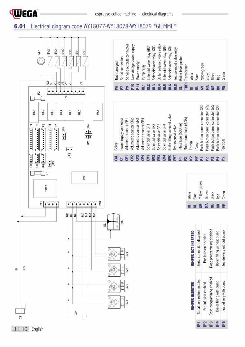
espresso coffee machine - electrical diagrams
ELE 10
R
English
6.01 Electrical diagram code WY18077-WY18078-WY18079 *GIEMME*
P10
P11
P9
F1
JP2
JP1 JP4
JP6
F2
JP3
TRF1
RL1
RL2
RL3
RL4
RL5
RL6
RL8
P1
P2
P3
P4
P6
P5
P8
IC2
P7
EV1
EVT
EV4
EVC
EV3
EV2
MP
-
CV1
+O
-+
CV2
CV3
O
-+
O
CV4
+O
-
CT
RO
BI
NE
BL
NE
MA
MA
MA
MA
GV
RO
BL
VE
VE
VE
VE
VE
VE
SL CAL
CAL
B
oiler
CT
P
ower
sup
ply
conn
ecto
rCV
1
Vol
umet
ric c
ount
er G
R1CV
2
Vol
umet
ric c
ount
er G
R2CV
3
Vol
umet
ric c
ount
er G
R3CV
4
Vol
umet
ric c
ount
er G
R4EV
1
Sol
enoi
d va
lve G
R1EV
2
Sol
enoi
d va
lve G
R2EV
3
Sol
enoi
d va
lve G
R3EV
4
Sol
enoi
d va
lve G
R4EV
C
Boi
ler fi
lling
solen
oid
valve
EVT
Te
a so
lenoi
d va
lveF1
Inlet
s fu
se (5
00m
A)F2
Mot
or p
ump
fuse
(6,3
A)IC
2
Epr
omM
P
Pum
pP1
Push
but
ton
pane
l con
nect
or G
R1P2
Push
but
ton
pane
l con
nect
or G
R2P3
Push
but
ton
pane
l con
nect
or G
R3P4
Push
but
ton
pane
l con
nect
or G
R4P5
Tea
dose
P6
No
t man
aged
P7
Se
rial c
onne
ctio
nP9
Serv
ice o
utpu
ts c
onne
ctor
P10
Lo
w vo
ltage
pow
er s
uppl
yP1
1
Powe
r sup
ply
RL1
Pu
mp
relay
RL2
So
lenoi
d va
lve re
lay G
R2RL
3
Solen
oid
valve
relay
GR3
RL4
Bo
iler s
olen
oid
valve
relay
RL
5
Solen
oid
valve
relay
GR4
RL6
So
lenoi
d va
lve re
lay G
R1RL
8
Tea
solen
oid
valve
relay
SL
Bo
iler l
evel
prob
eTR
F1 T
rans
form
erBI
Whi
teBL
Blue
GV
Yell
ow-g
reen
MA
B
rown
NE
Bl
ack
RO
Re
dVE
Gree
n
JP1
JP2
JP3
JP4
JP6
Seria
l con
nect
ion
enab
led
Pre-
infu
sion
enab
led
Dose
pro
gram
min
g en
abled
Boile
r filli
ng w
ith p
ump
Tea
deliv
ery
with
pum
p
Seria
l con
nect
ion
disa
bled
Pre-
infu
sion
disa
bled
Dose
pro
gram
min
g di
sabl
ed
Boile
r filli
ng w
ithou
t pum
p
Tea
deliv
ery
with
out p
ump
JUM
PER
INSE
RTED
JUM
PER
NOT
INSE
RTED
BI
Wh
iteBL
B
lue
GV
Yell
ow-g
reen
MA
B
rown
NE
Blac
kRO
R
edVE
G
reen

espresso coffee machine - electrical diagramsR
ELE 11English
6.02 Electrical diagram code WY18077-WY18078-WY18079 *GICAR*
AN2
AN3
Jumpe
r bet
ween
1 an
d 2
Jumpe
r bet
ween
2 an
d 3
Jumpe
r bet
ween
1 an
d 2
Jumpe
r bet
ween
2 an
d 3
Pre-
infu
sion
OFF
Pre-
infu
sion
ON
Prog
ram
min
g OF
F
Prog
ram
min
g ON
JUM
PER
ACTI
VATI
ON
CN2
CN1
CN3
TR
EV1
EV4
EVC
EV3
EV2
MP
-
CV1
+
O
-+
CV2
CV3
O
-+
O
CV4
+
O
-
CT
F1F2
F3 F4 F5F6
CP1
CP2
CP3
CP4
AN3
AN2
UPF
UPR
TXD
RXD
GN
AN2
AN3
CAL
SL
NE
BL
NE
MA
MA
MA
MA
GV
RO
BL
VE
VE
VE
VE
VE
BI
RO
CP5
CP5
CP4
CP3
CP2
CP1
F0VER
VER
F0
In
lets
fuse
(0.1
25a)
F1
P
ump
fuse
(6.3
A)F2
Sol
enoi
d va
lve fu
se G
R2 (1
A)F3
Sol
enoi
d va
lve fu
se G
R3 (1
A)F4
Boi
ler s
olen
oid
valve
fuse
(1A
)F5
Sol
enoi
d va
lve fu
se G
R4 (1
A)F6
Sol
enoi
d va
lve fu
se G
R1 (1
A)CP
1
Pus
h bu
tton
pane
l con
nect
or G
R1CP
2
Pus
h bu
tton
pane
l con
nect
or G
R2CP
3
Pus
h bu
tton
pane
l con
nect
or G
R3CP
4
Pus
h bu
tton
pane
l con
nect
or G
R4CP
5
Ser
ial c
onne
ctor
CN1
S
ervic
e ou
tput
s co
nnec
tor
CN2
L
ow v
olta
ge p
ower
sup
ply
CN3
P
ower
sup
ply
conn
ecto
rSL
Lev
el pr
obe
TR
T
rans
form
erUP
F
Pre
-infu
sion
outp
utUP
R
Pro
gram
min
g ou
tput
VER
V
ertic
al pr
inte
d cir
cuit
CAL
B
oiler
CT
P
ower
sup
ply
conn
ecto
rCV
1
Vol
umet
ric c
ount
er G
R1CV
2
Vol
umet
ric c
ount
er G
R2CV
3
Vol
umet
ric c
ount
er G
R3CV
4
Vol
umet
ric c
ount
er G
R4D
Sele
ctio
n co
unte
rEV
1
Solen
oid
valve
GR1
EV2
So
lenoi
d va
lve G
R1EV
3
Solen
oid
valve
GR1
EV4
So
lenoi
d va
lve G
R1EV
C
Fillin
g so
lenoi
d va
lve B
oiler
BI
Wh
iteBL
B
lue
GV
Yell
ow-g
reen
MA
Br
own
NE
Blac
kRO
R
edVE
G
reen

espresso coffee machine - electrical diagrams
ELE 12
R
English

espresso coffee machine - electrical diagramsR
ELE 13English
6.04 Electrical diagram code WY18362-WY18363-WY18365-WY18366
CV
+
O
-
TR
CN2
CN3
CN4
CM
CN1
SPIA
CT
IP
SL
CAL
EVE
MP
EVC
CAL
Bo
iler
CM
Mem
bran
e co
nnec
tion
CN1
Po
wer s
upply
and s
ervic
es ou
tputs
CN2
Do
sing
devic
e ou
tput
CN3
Pr
ogra
mm
ing
switc
hCN
4
Boile
r lev
elCT
Powe
r sup
ply
conn
ecto
rCV
Volu
met
ric c
ount
er
EVC
Fil
ling
solen
oid
valve
EVE
De
liver
y so
lenoi
d va
lveIP
Pro
gram
min
g sw
itch
MP
P
ump
SL
L
evel
prob
eSP
IA
On in
dica
tor l
ight
TR
T
rans
form
er

espresso coffee machine - electrical diagrams
ELE 14
R
English
6.05 Electrical diagram code WY18090016-WY18090017
CAL
Bo
iler
CT
Po
wer s
uppl
y co
nnec
tor
CV1
Vo
lum
etric
cou
nter
GR1
CV2
Vo
lum
etric
cou
nter
GR2
CV3
Vo
lum
etric
cou
nter
GR3
CV4
Vo
lum
etric
cou
nter
GR4
EV1
So
lenoi
d va
lve G
R1EV
2
Solen
oid
valve
GR2
EV3
So
lenoi
d va
lve G
R3EV
4
Solen
oid
valve
GR4
EVC
Bo
iler f
illing
sol
enoi
d va
lveEV
T
Tea
solen
oid
valve
F1
In
lets
fuse
(500
mA)
F2
M
otor
pum
p fu
se (6
,3A)
IC2
E
prom
MP
P
ump
P1
Pu
sh bu
tton p
anel
conn
ecto
r GR1
P2
Pu
sh bu
tton p
anel
conn
ecto
r GR2
P3
Pu
sh bu
tton p
anel
conn
ecto
r GR3
P4
Pu
sh bu
tton p
anel
conn
ecto
r GR4
P5
Te
a dos
eP6
Not m
anag
edP7
Seria
l con
necti
onP9
Serv
ice ou
tputs
conn
ecto
rP1
0
Low
volta
ge po
wer s
upply
P11
Po
wer s
upply
RL1
Pu
mp re
layRL
2
Solen
oid va
lve re
lay G
R2RL
3
Solen
oid va
lve re
lay G
R3RL
4
Boile
r sole
noid
valve
relay
RL
5
Solen
oid va
lve re
lay G
R4RL
6
Solen
oid va
lve re
lay G
R1RL
8
Tea s
oleno
id va
lve re
laySL
Boil
er le
vel p
robe
TRF
Tr
ansfo
rmer
JP1
JP2
JP3
JP4
JP5
Seria
l con
nect
ion
enab
led
Pre-
infu
sion
enab
led
Dose
pro
gram
min
g en
abled
Tea
deliv
ery
with
pum
p
Tea
key
enab
led
Seria
l con
nect
ion
disa
bled
Pre-
infu
sion
disa
bled
Dose
pro
gram
min
g di
sabl
ed
Tea
deliv
ery
with
out p
ump
Tea
key
disa
bled
JUM
PER
INSE
RTED
JUM
PER
NOT
INSE
RTED
EV1
EVT
EV4
EVC
EV3
MP
EV2
P10
P11
P9
F1
JP4
JP6
JP3
JP2
JP1
F2
JP5
RL1
RL2
RL3
RL4
RL5
RL6
RL8
P1 P2 P3 P4
P6P5 P7
IC2
O
CV3
CV1
+
O
-
CV2
+
O
-+
CV4
+-
O
-
CT
TR
SL
CAL
RO BL VE VE VE VE VE VE
NEBL NE
MA
MA
MA
MA
ROBI
GV
BI
Wh
iteBL
B
lue
GV
Yell
ow-g
reen
MA
B
rown
NE
Bl
ack
RO
Re
dVE
Gree
n

espresso coffee machine - electrical diagramsR
ELE 15English
6.06 Electrical diagram code WY18090016-WY18090017
CAL
Boi
lerCT
P
ower
sup
ply
conn
ecto
rCV
1 V
olum
etric
cou
nter
GR1
CV2
Vol
umet
ric c
ount
er G
R2CV
3 V
olum
etric
cou
nter
GR3
EV1
Sol
enoi
d va
lve G
R1EV
2 S
olen
oid
valve
GR2
EV3
Sol
enoi
d va
lve G
R3EV
C B
oiler
fillin
g so
lenoi
d va
lveEV
T T
ea s
olen
oid
valve
F2
Inl
ets
fuse
(500
mA)
F4
Mot
or p
ump
fuse
(6.3
A)
+
CV2
CV1
-+
CV3
-+
-
CV4
+-
OO
OO
CT
SL
CAL
RO BL VE VE VE VE VE VE
ROBI
NEBL NE
MA
MA
MA
MA
GV
CN1
CN2
CN3
EV1
EVT
EV4
EVC
EV3
MP
EV2
CT2
CT1
CT3
CT4
TE1
TE2
CLS
F2
JP4
JP6
JP8
JP3
JP5
JP2
JP1
F4
VAL
TXD
RXD
GN
MP
Pump
CT1
P
ush
butto
n pa
nel c
onne
ctor G
R1CT
2
Pus
h bu
tton
pane
l con
necto
r GR2
CT3
P
ush
butto
n pa
nel c
onne
ctor G
R3CT
4
Pus
h bu
tton
pane
l con
necto
r GR4
TE1
T
ea d
ose
TE2
N
ot m
anag
edCL
S
Se
rial c
onne
ction
CN1
P
ower
supp
ly CN
2
Low
volta
ge p
ower
supp
lyCN
3
Ser
vice o
utpu
ts co
nnec
tor
SL
Boile
r lev
el pr
obe
JP1
JP2
JP3
JP4
JP5
JP6
JP8
Seria
l con
nect
ion
enab
led
Pre-
infu
sion
enab
led
Dose
pro
gram
min
g en
abled
Boile
r filli
ng w
ith p
ump
Conf
igur
atio
n “W
”
Tea
deliv
ery
with
pum
p
Cont
rol D
Seria
l con
nect
ion
disa
bled
Pre-
infu
sion
disa
bled
Dose
pro
gram
min
g di
sabl
ed
Boile
r filli
ng w
ithou
t pum
p
Conf
igur
atio
n “C
”
Tea
deliv
ery
with
out p
ump
I/O In
terfa
ce
JUM
PER
INSE
RTED
JUM
PER
NOT
INSE
RTED
BI
Wh
iteBL
B
lue
GV
Yell
ow-g
reen
MA
B
rown
NE
Blac
kRO
R
edVE
G
reen
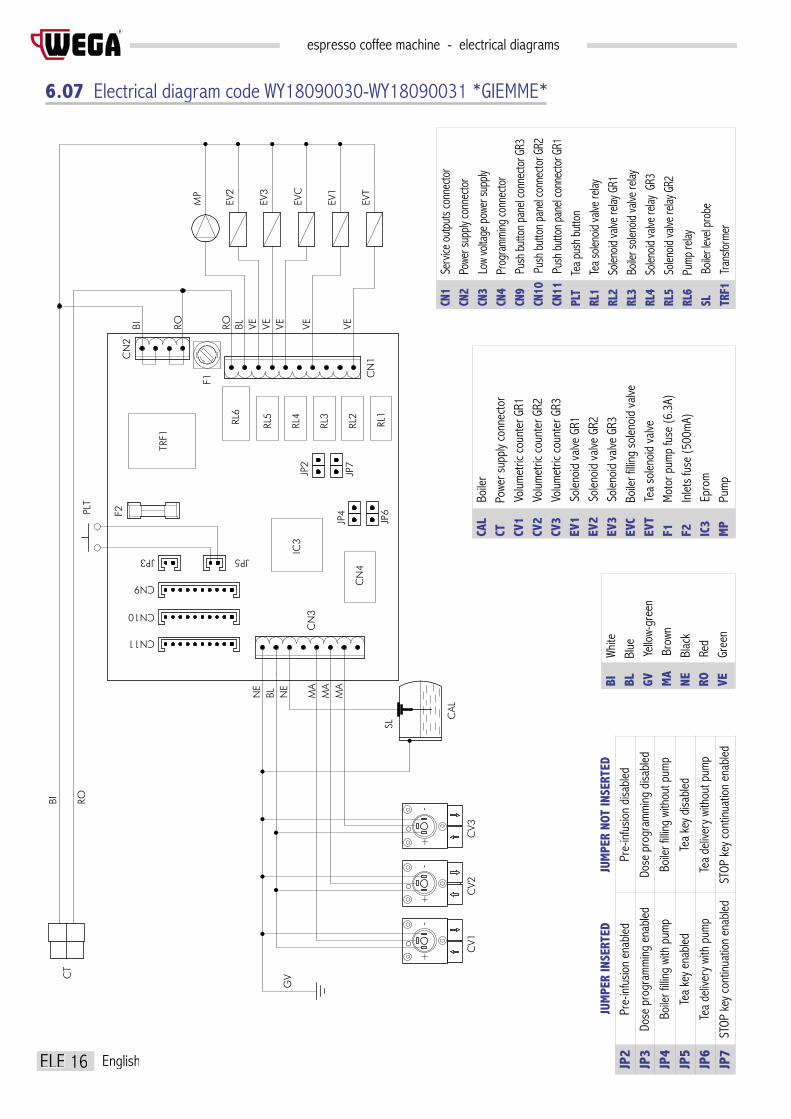
espresso coffee machine - electrical diagrams
ELE 16
R
English
6.07 Electrical diagram code WY18090030-WY18090031 *GIEMME*
CAL
B
oiler
CT
P
ower
sup
ply
conn
ecto
rCV
1
Vol
umet
ric c
ount
er G
R1CV
2
Vol
umet
ric c
ount
er G
R2CV
3
Vol
umet
ric c
ount
er G
R3EV
1
Sol
enoi
d va
lve G
R1EV
2
Sol
enoi
d va
lve G
R2EV
3
Sol
enoi
d va
lve G
R3EV
C
Boi
ler fi
lling
solen
oid
valve
EVT
Te
a so
lenoi
d va
lveF1
Mot
or p
ump
fuse
(6.3
A)F2
Inlet
s fu
se (5
00m
A)IC
3
Epr
omM
P
Pum
p
EVT
EVC
EV3
MP
EV2
CN3
CT
CN1
F2
JP7
JP2
EV1
TRF1
JP6
JP4
JP3 JP5
PLT
F1
CV1
+
O
CV2
-+
O
-
CV3
+
O
-
CN4
IC3
RL1
RL2
RL3
RL4
RL5RL6
CAL
SL
CN2
CN11
CN10
CN9
RO BL VE VE VE VEVEROBI
NE
MA
MA
MA
BLNE
GV
ROBI
CN1
S
ervic
e out
puts
conn
ecto
rCN
2
Pow
er su
pply
conn
ecto
rCN
3
Low
volta
ge p
ower
supp
lyCN
4
Pro
gram
ming
conn
ecto
rCN
9
Pus
h bu
tton
pane
l con
necto
r GR3
CN10
Pu
sh b
utto
n pa
nel c
onne
ctor G
R2CN
11
Push
but
ton
pane
l con
necto
r GR1
PLT
Te
a pus
h bu
tton
RL1
Te
a sole
noid
valve
relay
RL2
S
oleno
id va
lve re
lay G
R1RL
3
Boil
er so
lenoid
valve
relay
RL
4
Sole
noid
valve
relay
GR3
RL5
S
oleno
id va
lve re
lay G
R2RL
6
Pum
p re
laySL
Boil
er le
vel p
robe
TRF1
Tr
ansfo
rmer
JP2
JP3
JP4
JP5
JP6
JP7
Pre-
infu
sion
enab
led
Dose
pro
gram
min
g en
abled
Boile
r filli
ng w
ith p
ump
Tea
key
enab
led
Tea
deliv
ery
with
pum
p
STOP
key
con
tinua
tion
enab
led
Pre-
infu
sion
disa
bled
Dose
pro
gram
min
g di
sabl
ed
Boile
r filli
ng w
ithou
t pum
p
Tea
key
disa
bled
Tea
deliv
ery
with
out p
ump
STOP
key
con
tinua
tion
enab
led
JUM
PER
INSE
RTED
JUM
PER
NOT
INSE
RTED
BI
Wh
iteBL
B
lue
GV
Yell
ow-g
reen
MA
B
rown
NE
Blac
kRO
R
edVE
G
reen

espresso coffee machine - electrical diagramsR
ELE 17English
6.08 Electrical diagram code WY18090030-WY18090031 *GICAR*
EVT
EVC
EV3
MP
EV2
CV1
CT
F1
JP4
JP6
JP7
JP5
JP2
JP1
JP8
EV1
TR
-+
O
CV2
CV3
+
O
-+
O
-
JP8
CAL
SL
BL MA
NE
MA
MA
NE
BI RO
GV
VEVEBL VE VEROBI RO
CN3
CN4
CN5
CN7
CN2
CN6
VE
JP1
JP2
JP3
JP4
JP5
JP6
JP7
JP8
Not m
anag
ed
Pre-
infu
sion
enab
led
Dose
pro
gram
min
g en
abled
Boile
r filli
ng w
ith p
ump
Tea
key
enab
led
Tea
deliv
ery
with
pum
p
Not m
anag
ed
Not m
anag
ed
Not m
anag
ed
Pre-
infu
sion
disa
bled
Dose
pro
gram
min
g di
sabl
ed
Boile
r filli
ng w
ithou
t pum
p
Tea
key
disa
bled
Tea
deliv
ery
with
out p
ump
Not m
anag
ed
Not m
anag
ed
JUM
PER
INSE
RTED
JUM
PER
NOT
INSE
RTED
CAL
Bo
iler
CT
Po
wer s
uppl
y co
nnec
tor
CV1
Vo
lum
etric
cou
nter
GR1
CV2
Vo
lum
etric
cou
nter
GR2
CV3
Vo
lum
etric
cou
nter
GR3
EV1
So
lenoi
d va
lve G
R1EV
2
Solen
oid
valve
GR2
EV3
So
lenoi
d va
lve G
R3EV
C
Boile
r filli
ng s
olen
oid
valve
EVT
Te
a so
lenoi
d va
lve
F1
Inl
ets f
use (
500m
A)M
P
Pum
pCN
2
Powe
r sup
plyCN
3
Push
but
ton
pane
l con
necto
r GR1
CN4
Pu
sh b
utto
n pa
nel c
onne
ctor G
R2CN
5
Push
but
ton
pane
l con
necto
r GR3
CN6
Se
rvice
out
puts
conn
ecto
rCN
7
Low
volta
ge p
ower
supp
lySL
Boil
er le
vel p
robe
TR
Tr
ansfo
rmer
BI
Wh
iteBL
B
lue
GV
Yell
ow-g
reen
MA
B
rown
NE
Blac
kRO
R
edVE
G
reen

espresso coffee machine - electrical diagrams
ELE 18
R
English
6.11 Electrical diagram code WY18090047-48 *POLARIS-VENUS* PLUS 1 rev.0
EV1
TLR
EVC
EV3
MP
EV2
CT
RL9
RL6
RL4
RL3
RL2
RL1
F1
TRF2
JP5
JP3
CN5
JP6
JP4
F2
JP7
JP15
JP18 JP2
JP9
JP17 JP1
JP8
JP16
IC4
TXD
RXD
GND
CV3
CV1
+
O
-
CV2
+
O
-+
-
O
JP12
JP14
RL10
CN6
CV4
+
O
-
EV4
SL
CAL
CN1
CN2
CN14
CN10
CN11
CN12
CN13
CN6
CN7
CN4
BL MA
MA
MA
MA
NE
NE
GV
ROBI
MA
VE VE VE VEVEBLRO
EVT
VE
RL5
RL8
RL7
JP1
JP2
JP4
JP6
JP7
JP8
JP9
JP12
JP14
JP15
JP16
JP17
JP18
Seria
l tra
nsm
issio
n en
abled
Pre-
infu
sion
enab
led
Boile
r filli
ng w
ith p
ump
Tea
deliv
ery
with
pum
p
STOP
key
con
tinua
tion
enab
led
Not m
anag
ed
Rese
t car
d so
ftwar
e
Not m
anag
ed
Not m
anag
ed
Not m
anag
ed
6-ke
y do
sing
devic
e en
abled
Not m
anag
ed
Not m
anag
ed
Seria
l tra
nsm
issio
n di
sabl
ed
Pre-
infu
sion
disa
bled
Boile
r filli
ng w
ithou
t pum
p
Tea
deliv
ery
with
out p
ump
STOP
key
con
tinua
tion
enab
led
Not m
anag
ed
------
-
Not m
anag
ed
Not m
anag
ed
Not m
anag
ed
6-ke
y do
sing
devic
e di
sabl
ed
Not m
anag
ed
Not m
anag
ed
JUM
PER
INSE
RTED
JUM
PER
NOT
INSE
RTED
CV1
V
olum
etric
coun
ter G
R1CV
2
Volu
met
ric co
unte
r GR2
CV3
V
olum
etric
coun
ter G
R3CV
4
Volu
met
ric co
unte
r GR4
EV1
S
oleno
id va
lve G
R1EV
2
Sole
noid
valve
GR1
EV3
S
oleno
id va
lve G
R1EV
4
Sole
noid
valve
GR1
EVC
B
oiler
fillin
g so
lenoid
valve
EVT
Te
a so
lenoid
valve
RL1
Te
a so
lenoid
valve
relay
RL2
S
oleno
id va
lve re
lay G
R2RL
3
Sole
noid
valve
relay
GR3
RL4
B
oiler
solen
oid va
lve re
lay
RL5
S
oleno
id va
lve re
lay G
R4RL
6
Sole
noid
valve
relay
GR1
RL7
O
n/of
f rela
yRL
8
Boil
er h
eatin
g ele
men
t rela
yRL
9
Tea
solen
oid va
lve re
layRL
10
Cup
heat
er h
eatin
g ele
men
t rela
y
BI
Wh
iteBL
B
lue
GV
Yell
ow-g
reen
MA
B
rown
NE
Blac
kRO
R
edVE
G
reen
CAL
B
oiler
CT
P
ower
supp
ly co
nnec
tor
F1
M
otor
pum
p fu
se (6
.3A)
F2
In
lets f
use
(500
mA)
IC4
M
icrop
roce
ssor
MP
P
ump
SL
L
evel
prob
eTL
R
Rem
ote
switc
hTR
F2 T
rans
form
erCN
1
Powe
r sup
ply co
nnec
tor
CN2
Lo
w vo
ltage
pow
er su
pply
CN4
S
erial
tran
smiss
ion co
nnec
tor
CN5
No
t man
aged
CN6
Ve
rtica
l card
cup h
eater
heati
ng el
emen
tCN
7
Cup h
eater
temp
eratur
e prob
e con
necto
rCN
10 P
ush
butto
n pa
nel c
onne
ctor G
R1CN
11 P
ush
butto
n pa
nel c
onne
ctor G
R2CN
12 P
ush
butto
n pa
nel c
onne
ctor G
R3CN
13 P
ush
butto
n pa
nel c
onne
ctor G
R4CN
14 S
ervic
e ou
tput
s con
necto
rJP
3
Pro
gram
ming
JP5
Te
a do
se

espresso coffee machine - electrical diagramsR
ELE 19English
6.13 Electrical diagram code WY18090037-38 *POLARIS-VENUS* PLUS 2 rev.0
JP1
JP2
JP4
JP6
JP7
JP8
JP9
JP12
JP14
JP15
JP16
JP17
JP18
Seria
l tra
nsm
issio
n en
abled
Pre-
infu
sion
enab
led
Boile
r filli
ng w
ith p
ump
Tea
deliv
ery
with
pum
p
STOP
key
con
tinua
tion
enab
led
Not m
anag
ed
Rese
t car
d so
ftwar
e
Not m
anag
ed
Not m
anag
ed
Keyp
ad fu
nctio
n ke
ys e
nabl
ed
6-ke
y do
sing
devic
e en
abled
Not m
anag
ed
Not m
anag
ed
Seria
l tra
nsm
issio
n di
sabl
ed
Pre-
infu
sion
disa
bled
Boile
r filli
ng w
ithou
t pum
p
Tea
deliv
ery
with
out p
ump
STOP
key
con
tinua
tion
enab
led
Not m
anag
ed
------
-
Not m
anag
ed
Not m
anag
ed
Disp
lay fu
nctio
n ke
ys e
nabl
ed
4-ke
y do
sing
devic
e en
abled
Not m
anag
ed
Not m
anag
ed
JUM
PER
INSE
RTED
JUM
PER
NOT
INSE
RTED
SL
-
CV2
CV1O
-
CV3
-
OO
CV4O
-
CAL
CN6
RL10
GV
CT
ROBI
MA
CN2
MA
MA
MA
NEBL
F2
CN5
TRF2
NE
CN1
JP14
CN4 JP12
JP3
JP7
JP4
JP6
IC4
JP8
JP16JP1
JP17
JP18 JP2
JP9
JP15
CN6CN12
CN13
CN11
JP5
CN7
CN10
RL9
RL8
RL7
RL6
F1
RL5
RL4
CN14
RL3
RL2
RL1
CN3
JP10
CN8
GND
RX
Vcc TX
TLR
EVT
VE MA
VEVE VEVEVEBLRO
EV3
EVC
EV1
EV4
EV2
MP
CAL
B
oiler
CT
P
ower
supp
ly co
nnec
tor
F1
M
otor
pum
p fu
se (6
.3A)
F2
In
lets f
use
(500
mA)
IC4
M
icrop
roce
ssor
MP
P
ump
SL
L
evel
prob
eTL
R
Rem
ote
switc
hTR
F2 T
rans
form
erCN
1
Powe
r sup
ply co
nnec
tor
CN2
Lo
w vo
ltage
pow
er su
pply
CN3
Di
splay
conn
ecto
rCN
4
Ser
ial tr
ansm
ission
conn
ecto
rCN
5
Not m
anag
edCN
6
Verti
cal ca
rd cu
p hea
ter he
ating
elem
ent
CN7
Cu
p hea
ter te
mpera
ture p
robe c
onne
ctor
CN8
Bo
iler p
robe
conn
ecto
rCN
10 P
ush
butto
n pa
nel c
onne
ctor G
R1CN
11 P
ush
butto
n pa
nel c
onne
ctor G
R2CN
12 P
ush
butto
n pa
nel c
onne
ctor G
R3CN
13 P
ush
butto
n pa
nel c
onne
ctor G
R4CN
14 S
ervic
e ou
tput
s con
necto
rJP
3
Pro
gram
ming
JP5
Te
a do
se
CV1
V
olum
etric
coun
ter G
R1CV
2
Volu
met
ric co
unte
r GR2
CV3
V
olum
etric
coun
ter G
R3CV
4
Volu
met
ric co
unte
r GR4
EV1
S
oleno
id va
lve G
R1EV
2
Sole
noid
valve
GR1
EV3
S
oleno
id va
lve G
R1EV
4
Sole
noid
valve
GR1
EVC
F
illing
solen
oid v
alve
Boile
rEV
T
Tea
solen
oid v
alve
RL1
Te
a so
lenoid
valv
e re
layRL
2
Sole
noid
valve
relay
GR2
RL3
S
oleno
id va
lve re
lay G
R3RL
4
Boil
er so
lenoid
valv
e re
lay
RL5
S
oleno
id va
lve re
lay G
R4RL
6
Sole
noid
valve
relay
GR1
RL7
O
n/of
f rela
yRL
8
Boil
er h
eatin
g ele
men
t rela
yRL
9
Tea
solen
oid v
alve
relay
RL10
Cu
p he
ater
hea
ting
elem
ent r
elay
BI
Wh
iteBL
B
lue
GV
Yell
ow-g
reen
MA
B
rown
NE
Blac
kRO
R
edVE
G
reen
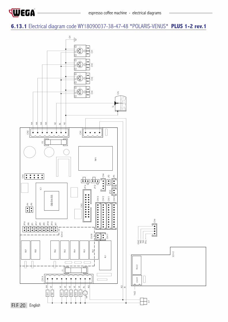
espresso coffee machine - electrical diagrams
ELE 20
R
English
6.13.1 Electrical diagram code WY18090037-38-47-48 *POLARIS-VENUS* PLUS 1-2 rev.1
SL
F1
BLMP
CT
RO RO BI
CN19
EVT
TLR
EV4
EV1
EVC
EV3
EV2
CN14
MA
VE VE VE VEVE VE
IC1
RL3
RL2
RL1
RL5-2
SCH-2
CN17
CN18
5Vcc
RXD
TXD
GND
RL4
RL6
RL8
RL9
SCH-2
CN4
JP10
CN10
CN12
CN11
CN13
JP7
JP18
JP15
JP9
JP2
JP17
JP1
JP16
JP8
08/04/05
CN3JP6
JP4
JP5
JP3
CN4
JP12
JP14
TRF1
CN5
CN1
F2
CN2
MA
MA
MA
MA
NE
BL NE
CV2
CALCV4
CV3
O
-
O
-
O
CV1O
--
GV
RL5
TAZZ

espresso coffee machine - electrical diagramsR
ELE 21English
CN1
P
ower
supp
ly co
nnec
tor
CN2
L
ow vo
ltage
pow
er su
pply
CN3
D
isplay
conn
ecto
r
CN4
S
erial
tran
smiss
ion co
nnec
tor
CN5
M
icrop
roce
ssor
conn
ecto
r
CN10
P
ush
butto
n pa
nel c
onne
ctor G
R1
CN11
P
ush
butto
n pa
nel c
onne
ctor G
R2
CN12
P
ush
butto
n pa
nel c
onne
ctor G
R3
CN13
P
ush
butto
n pa
nel c
onne
ctor G
R4
CN14
S
ervic
e ou
tput
s con
necto
r
CN17
C
onne
ctor b
oiler
NTC
CN18
C
onne
ctor C
up h
eate
r NTC
CN19
C
onne
ctor C
up h
eate
r hea
ting
el.
CT
P
ower
supp
ly co
nnec
tor
CAL
B
oiler
IC1
Micr
opro
cess
or
MP
Pum
p
TLR
R
emot
e sw
itch
TRF1
T
rans
form
er
TAZZ
C
up h
eate
r
BI
White
BL
Blue
GV
Yello
w-gr
een
MA
Bro
wn
NE
Blac
k
RO
Red
VE
Gree
n
CV1
V
olum
etric
coun
ter G
R1
CV2
V
olum
etric
coun
ter G
R2
CV3
V
olum
etric
coun
ter G
R3
CV4
V
olum
etric
coun
ter G
R4
EV1
S
oleno
id va
lve G
R1
EV2
S
oleno
id va
lve G
R2
EV3
S
oleno
id va
lve G
R3
EV4
S
oleno
id va
lve G
R4
EVC
F
illing
solen
oid v
alve
Boile
r
EVT
T
ea so
lenoid
valv
e
F1
O
uput
s fu
se (6
,3A)
F2
I
nput
s fu
se (5
00m
A)
RL1
S
oleno
id va
lve re
lay P
ump
RL2
S
oleno
id va
lve re
lay G
R2
RL3
S
oleno
id va
lve re
lay G
R3
RL4
S
oleno
id va
lve re
lay B
oiler
RL5
S
oleno
id va
lve re
lay G
R4
RL6
S
oleno
id va
lve re
lay G
R1
RL8
B
oiler
hea
ting
elem
ent r
elay
RL9
S
oleno
id va
lve re
lay Te
a
RL5-
2 S
oleno
id va
lve re
lay cu
p he
ater
JP1
JP2
JP3
JP4
JP5
JP6
JP7
JP8
JP9
JP10
JP12
JP14
JP15
JP16
JP17
JP18
Seria
l tra
nsm
issio
n
Pre-
infu
sion
Prog
ram
min
g
Boile
r filli
ng
Tea
deliv
ery
Tea
STOP
key
con
tinua
tion
Not m
anag
ed
Cred
it-De
bt
Not m
anag
ed
Not m
anag
ed
Not m
anag
ed
Disp
lay fu
nctio
n ke
ys
Devic
e
Not m
anag
ed
Not m
anag
ed
Enab
led
Enab
led
With
pum
p
With
pum
p
Disa
bled
Enab
led
Enab
led
6-ke
y do
sing
INSE
RTED
NOT
INSE
RTED
Disa
bled
Disa
bled
With
out p
ump
With
out p
ump
Enab
led
Disa
bled
Disa
bled
4-ke
y do
sing
(*)
JP12
JP14
JP12
JP14CRED
IT-DE
BTIN
TERF
ACE
I/O
Conf
igur
atio
n JP
12-
JP14
For v
ersio
n wh
itout
DIS
PLAY
: not
man
aged
JP15
(*)

espresso coffee machine - electrical diagrams
ELE 22
R
English
6.14 Electrical diagram code WY18090051-52 *POLARIS* PLUS 3 rev.0
SL
GND
CN20
CT
RL4-2
RL3-2
RL1-2
RL2-2SCH-2
TXD
RXD
5Vcc
CN4
F1
MP
EV2
EV3
EVC
EV1
EV4
TLR
EVT
CN19
BIROROBLVEVE VEVEVEVEMA
CN14
IC1
RL9
RL8
RL6
RL4
RL3
RL2
CN15
RL5-2
RL1
SCH-2
CN18
CN17
CN16
JP8
JP16
JP1
JP17
JP2
JP9
JP15
JP18
JP7
JP4
JP6
CN13
CN3
08/04/05
CN11
CN12
CN10
JP10
CN5
CN4
JP3
JP5
TRF1
CN2
F2
CN1
NE
BLNE
MA
MA
MA
MA
CV2
CV4
CAL
-
O
CV3
O
-
O
CV1
--
O
GV
JP14
JP12
PLAT
VAP1
VAP2
ARIA
TAZZ

espresso coffee machine - electrical diagramsR
ELE 23English
CN1
P
ower
supp
ly co
nnec
tor
CN2
L
ow vo
ltage
pow
er su
pply
CN3
D
isplay
conn
ecto
r
CN4
S
erial
tran
smiss
ion co
nnec
tor
CN5
M
icrop
roce
ssor
conn
ecto
r
CN10
P
ush
butto
n pa
nel c
onne
ctor G
R1
CN11
P
ush
butto
n pa
nel c
onne
ctor G
R2
CN12
P
ush
butto
n pa
nel c
onne
ctor G
R3
CN13
P
ush
butto
n pa
nel c
onne
ctor G
R4
CN14
S
ervic
e ou
tput
s con
necto
r
CN15
C
onne
ctor p
ress
ure
switc
h
CN16
C
onne
ctor a
utos
team
er N
TC
CN17
C
onne
ctor b
oiler
NTC
CN18
C
onne
ctor C
up h
eate
r NTC
CN19
C
onne
ctor C
up h
eate
r hea
ting
el.
CN20
C
onne
ctor c
appu
ccin
o m
aker
CT
P
ower
supp
ly co
nnec
tor
CAL
B
oiler
IC1
Micr
opro
cess
or
MP
Pum
p
TLR
R
emot
e sw
itch
TRF1
T
rans
form
er
BI
White
BL
Blue
GV
Yello
w-gr
een
MA
Bro
wn
NE
Blac
k
RO
Red
VE
Gree
n
CV1
V
olum
etric
coun
ter G
R1
CV2
V
olum
etric
coun
ter G
R2
CV3
V
olum
etric
coun
ter G
R3
CV4
V
olum
etric
coun
ter G
R4
EV1
S
oleno
id va
lve G
R1
EV2
S
oleno
id va
lve G
R2
EV3
S
oleno
id va
lve G
R3
EV4
S
oleno
id va
lve G
R4
EVC
F
illing
solen
oid v
alve
Boile
r
EVT
T
ea so
lenoid
valv
e
ARIA
S
oleno
id va
lve a
ir
PLAT
S
oleno
id va
lve c
old
milk
TAZZ
C
up h
eate
r
VAP1
S
oleno
id va
lve s
team
hot
milk
VAP2
S
oleno
id va
lve a
utos
team
er
F1
O
uput
s fu
se (6
,3A)
F2
I
nput
s fu
se (5
00m
A)
RL1
S
oleno
id va
lve re
lay P
ump
RL2
S
oleno
id va
lve re
lay G
R2
RL3
S
oleno
id va
lve re
lay G
R3
RL4
S
oleno
id va
lve re
lay B
oiler
RL5
S
oleno
id va
lve re
lay G
R4
RL6
S
oleno
id va
lve re
lay G
R1
RL8
B
oiler
hea
ting
elem
ent r
elay
RL9
S
oleno
id va
lve re
lay Te
a
RL1-
2 S
oleno
id va
lve ca
ppuc
cino
mak
er
RL2-
2 S
oleno
id va
lve re
lay a
utos
team
er
RL3-
2 S
oleno
id va
lve re
lay a
ir
RL4-
2 S
oleno
id va
lve re
lay m
ilk p
ump
RL5-
2 S
oleno
id va
lve re
lay cu
p he
ater
JP1
JP2
JP3
JP4
JP5
JP6
JP7
JP8
JP9
JP10
JP12
JP14
JP15
JP16
JP17
JP18
Seria
l tra
nsm
issio
n
Not m
anag
ed
Prog
ram
min
g
Boile
r filli
ng
Tea
deliv
ery
Tea
STOP
key
con
tinua
tion
Pum
p co
ld m
ilk
Cred
it-De
bt
Not m
anag
ed
Not m
anag
ed
Not m
anag
ed
Disp
lay fu
nctio
n ke
ys
Devic
e
Not m
anag
ed
Not m
anag
ed
Enab
led
With
pum
p
With
pum
p
Disa
bled
Enab
led
Enab
led
Key
gr.1
6-ke
y do
sing
INSE
RTED
NOT
INSE
RTED
Disa
bled
With
out p
ump
With
out p
ump
Enab
led
Disa
bled
Disa
bled
Disp
lay
4-ke
y do
sing
JP12
JP14
JP12
JP14CRED
IT-DE
BTIN
TERF
ACE
I/O
Conf
igur
atio
n JP
12-
JP14
Chec
king
tem
pera
ture
boi
ler /
pres
sure
JP17
clo
sed
+ JP
18
close
dWh
it ca
ppuc
cino
mak
er
JP17
clo
sed
+ JP
18
open
Whit
elect
roni
c sy
stem

espresso coffee machine - electrical diagrams
ELE 24
R
English
6.22 Electrical diagram code WY18090012-13-14-15 *SPHERA*
EV1
EVT
EV4
EVC
EV3
MP
EV2
P10
CT
P11
P9
P2
P1
P3
P4
P5
P6
P7
F2
JP4
JP6
JP7
JP3
JP5
JP2
JP1
F4
VAL
TXD
RXD
GND
RO
BI
JP8
PLT
CV1
+-
OO
CV3
CV2
+
O
-+
-
CV4
+
O
-
GV
NE
BL
NE
MA
MA
MA
MA
RO
BL
VE
VE
VE
VE
VE
VE
SL
CAL
CAL
B
oiler
CT
P
ower
supp
ly co
nnec
tor
CV1
V
olum
etric
coun
ter G
R1CV
2
Volu
met
ric co
unte
r GR2
CV3
V
olum
etric
coun
ter G
R3CV
4
Volu
met
ric co
unte
r GR4
EV1
S
oleno
id va
lve G
R1EV
2
Sole
noid
valve
GR2
EV3
S
oleno
id va
lve G
R3EV
4
Sole
noid
valve
GR4
EVC
B
oiler
fillin
g so
lenoid
valve
EVT
Te
a so
lenoid
valve
F2
In
lets f
use
(500
mA)
F4
Mo
tor p
ump
fuse
(6.3
A)
JP5
C
onne
ctio
n te
a do
seM
P
Pum
pPL
T
Tea
dose
P1
Pu
sh b
utto
n co
nnec
tor G
R1P2
Push
but
ton
conn
ecto
r GR2
P3
Pu
sh b
utto
n co
nnec
tor G
R3P4
Push
but
ton
conn
ecto
r GR4
P5
Te
a do
seP6
Not m
anag
edP7
Seria
l tra
nsm
ission
conn
ecto
rP9
Serv
ice o
utpu
ts co
nnec
tor
P10
Lo
w vo
ltage
pow
er su
pply
P11
Po
wer s
upply
conn
ecto
rSL
Lev
el pr
obe
BI
W
hite
BL
Bl
ueGV
Yello
w-gr
een
MA
B
rown
NE
Bl
ack
RO
Re
dVE
Gree
n
JP1
JP2
JP3
JP4
JP6
JP7
JP8
Coun
t ena
bled
Pre-
infu
sion
enab
led
Prog
ram
min
g en
abled
Boile
r filli
ng w
ith p
ump
Tea
fillin
g wi
th p
ump
STOP
key
disa
bled
Cont
rol d
Coun
t disa
bled
Pre-
infu
sion
disa
bled
Prog
ram
min
g di
sabl
ed
Boile
r filli
ng w
ithou
t pum
p
Tea
fillin
g wi
thou
t pum
p
STOP
key
ena
bled
Inte
rface
I/O
JUM
PER
INSE
RTED
JUM
PER
NOT
INSE
RTED

espresso coffee machine - electrical diagramsR
ELE 25English
6.24 Electrical diagram code WY18090018 - WY18090019 *SPHERA DISPLAY*CT
FA5
FA4
FA2
FA1
CN1 CN2 CN3 CN4
IP
TG
SCB
C
SCD
P2
P1
FA2
FA1
RE
BA
FIG.A
FIG.B
MC
SL CAL
BA
B
atte
ryCA
L
Boil
erCM
Mem
bran
e co
nnec
tor
CN1
S
erial
tran
smiss
ion co
nnec
tor
CN2
N
ot m
anag
edCN
3
Lev
el pr
obe
conn
ecto
rCN
4
Pro
gram
min
g sw
ith c
onne
ctor
CN5
C
ircui
t boa
rd d
isplay
con
nect
orCT
Pow
er c
onne
ctor
IP
S
witc
h pr
ogra
mm
ing
MC
Mac
hine
RE
R
elay
SCB
C
ircui
t boa
rdSC
D
Disp
lay c
ircui
t boa
rdSL
Lev
el pr
obe
TG
C
onta
ctor
FIG.
A
C
onne
ctio
n Cir
cuit
boar
d - C
ircui
t boa
rd d
isplay
FIG.
B
Ju
mpe
rs


INTERFACE SYSTEM
ENGL
ISH
ESPRESSO COFFEE MACHINEUSE AND MAINTENANCE MANUAL
Instructions for the user
Via Santi, 9 - 40011 ANZOLA EMILIA (BO) - ITALYTel. +39.051.6500900 - Fax +39.051.733701
www.wega.it - [email protected]
R


Summary
1. STANDARD interface system .................................................................................................................. 4
1.1 MACHINE - INTERFACE connection ........................................................................................................................... 4
1.2 NOVA type machine system ......................................................................................................................................5
1.3 SPHERA type machine system .................................................................................................................................5
1.4 NOVA type machine electrical diagram version *GICAR* ........................................................................................ 6
1.5 NOVA type machine electrical diagram version *GIEMME* ..................................................................................... 7
1.6 SPHERA type machine electrical diagram version *GICAR* ..................................................................................... 8
1.7 SPHERA type machine electrical diagram version *GIEMME* ................................................................................. 9
2. VENUS interface system ...................................................................................................................... 10
2.1 MACHINE - INTERFACE connection ......................................................................................................................... 10
2.2 Venus 2003 type machine system .........................................................................................................................11
2.3 Venus 2004 PLUS 1-2 type machine system ........................................................................................................11
2.4 Venus 2003 type machine electrical diagram version *GICAR* ............................................................................12
2.5 Venus 2003 type machine electrical diagram version *GIEMME* .........................................................................13
2.6 Venus 2004 - PLUS 1-2 type machine electrical diagram (OLD version) ..........................................................14
2.7 Venus 2005 - PLUS 1-2 type machine electrical diagram (NEW version) .........................................................15

CNS 4 English
espresso coffee machine - interface systemR
1. STANDARD interface system
1.1 MACHINE - INTERFACE connection
K The switch must face downwardsNote To enable the interface, short circuit pins 33/34 of CN1
K
1 Z11 1
PIN RELAY GROUP DOSE KEY
12 Z12 1 23 Z13 1 34 Z14 1 45 Z15 1 56 Z16 1 67 Z21 2 18 Z22 2 29 Z23 2 3
10 Z24 2 411 Z25 2 512 Z26 2 613 Z31 3 114 Z32 3 215 Z33 3 316 Z34 3 417 Z35 4 5
18 Z36 4
PIN RELAY GROUP DOSE KEY
619 Z41 4 120 Z42 4 221 Z43 4 322 Z44 4 423 Z45 4 524 Z46 4 625 ZT1 TEA26 ZT2272829 HTW common signals30 HTW common signals313233 ABHART*34 GND*

English CNS 5
espresso coffee machine - interface systemR
1.2 NOVA type machine system
Components to be used in the INTERFACE - COFFEE MACHINE connection: • Code WY26001 26-relay interface• Code WY22550 Hartwall cable• Code WY22551 Power cable• Code WY22552 8-pole serial transmission cable
1.3 SPHERA type machine system
Components to be used in the INTERFACE - COFFEE MACHINE connection: • Code WY26011 26-relay interface• Code WY22550 Hartwall cable• Code WY22551 Power cable• Code WY22555 4-pole serial transmission cable
Also, replace the microprocessor according to the following rule: • if the GICAR control unit uses code 4GR8T 13/10/01• If the GIEMME control unit uses code D4DEG-R 12/03/03 as shown in the drawings

CNS 6 English
espresso coffee machine - interface systemR
1.4 NOVA type machine electrical diagram version *GICAR*
A Hartwall cable 8.9.28.51 code WY22550
REF. DESCRIPTION
B WhiteC Power cable 8.9.28.12 code WY22551D DosingE Serial transmission cable 8.9.28.13 code WY22552F Remove the jumper before connecting the serial cableG Place the lever in the PROG position only when programming coffee dosesI InterfaceN BlackR RedV Green
AI
C
D
E
G
RB
V
R
N
F
RBV
R (VCC+)
N (GND)

English CNS 7
espresso coffee machine - interface systemR
1.5 NOVA type machine electrical diagram version *GIEMME*
A Hartwall cable 8.9.28.51 code WY22550
REF. DESCRIPTION
B WhiteC Power cable 8.9.28.12 code WY22551D Serial transmission cable 8.9.28.13 code WY22552E DosingF Short circuit JP1G Never place the lever in the PROG position I InterfaceN BlackR RedV Green
AI
C
DE
F
G
RB
V
R
N
RBV
R (VCC+)
N (GND)
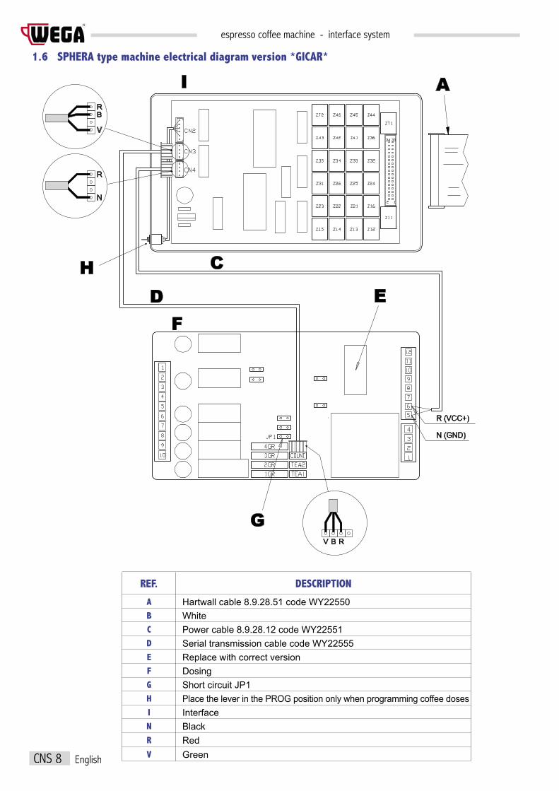
CNS 8 English
espresso coffee machine - interface systemR
1.6 SPHERA type machine electrical diagram version *GICAR*
A
C
D EF
G
H
IRB
V
R
N
RBV
R (VCC+)
N (GND)
A Hartwall cable 8.9.28.51 code WY22550
REF. DESCRIPTION
B WhiteC Power cable 8.9.28.12 code WY22551D Serial transmission cable code WY22555E Replace with correct versionF DosingG Short circuit JP1H Place the lever in the PROG position only when programming coffee dosesI InterfaceN BlackR RedV Green
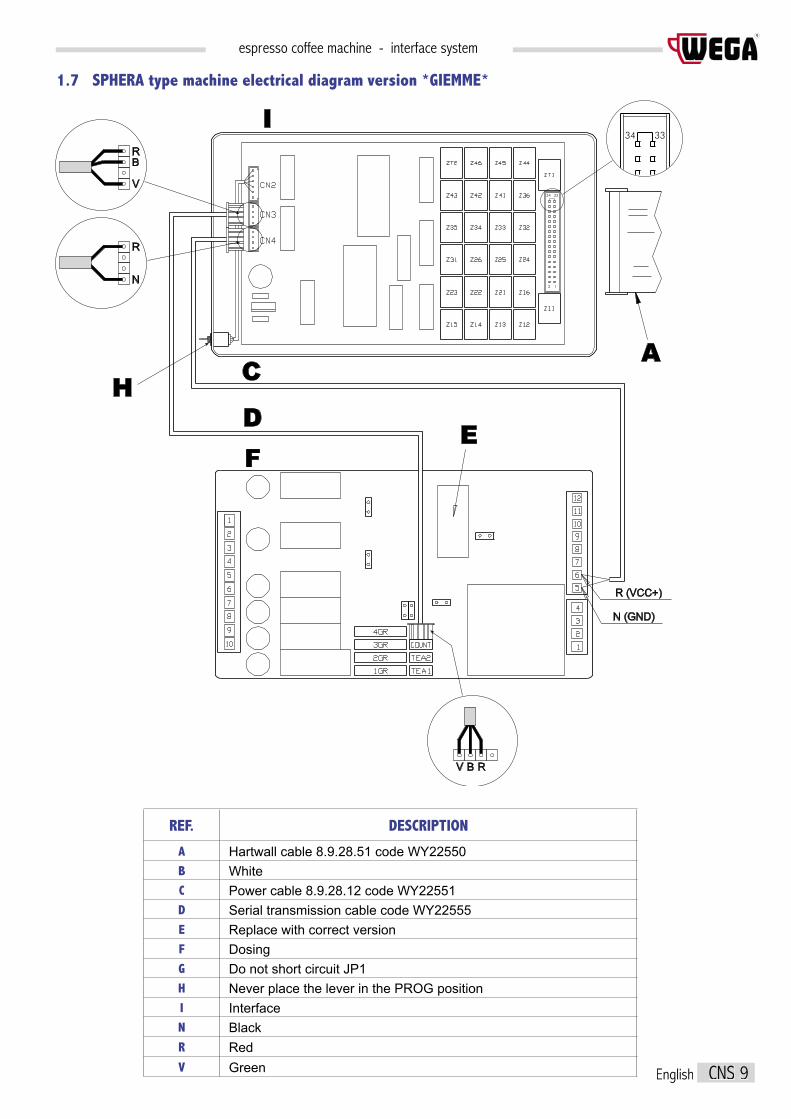
English CNS 9
espresso coffee machine - interface systemR
1.7 SPHERA type machine electrical diagram version *GIEMME*
A
I
C
DE
F
H
RB
V
R
N
R (VCC+)
N (GND)
RBV
34 33
34 33
2 1
A Hartwall cable 8.9.28.51 code WY22550
REF. DESCRIPTION
B WhiteC Power cable 8.9.28.12 code WY22551D Serial transmission cable code WY22555E Replace with correct versionF DosingG Do not short circuit JP1H Never place the lever in the PROG position I InterfaceN BlackR RedV Green

CNS 10 English
espresso coffee machine - interface systemR
2. VENUS interface system
2.1 MACHINE - INTERFACE connection
K The switch must face downwardsNote To enable the interface, short circuit pins 33/34 of CN1
K
1 Z11 1
PIN RELAY GROUP DOSE KEY
12 Z12 1 23 Z13 1 34 Z14 1 45 Z15 1 56 Z16 1 67 Z21 2 18 Z22 2 29 Z23 2 3
10 Z24 2 411 Z25 2 512 Z26 2 613 Z31 3 114 Z32 3 215 Z33 3 316 Z34 3 417 Z35 4 5
18 Z36 4
PIN RELAY GROUP DOSE KEY
619 Z41 4 120 Z42 4 221 Z43 4 322 Z44 4 423 Z45 4 524 Z46 4 625 ZT1 TEA26 ZT2272829 HTW common signals30 HTW common signals313233 ABHART*34 GND*

English CNS 11
espresso coffee machine - interface systemR
2.2 Venus 2003 type machine system
2.3 Venus 2004 PLUS 1-2 type machine system
Components to be used in the INTERFACE - COFFEE MACHINE connection: • Code WY26011 26-relay interface• Code WY22550 Hartwall cable• Code WY22551 Power cable• Code WY22555 4-pole serial transmission cable
Components to be used in the INTERFACE - COFFEE MACHINE connection: • Code WY26011 26-relay interface• Code WY22550 Hartwall cable• Code WY22551 Power cable• Code WY22555 4-pole serial transmission cable
WARNING
• This type of control unit has been replaced with the “PLUS 1-2” version, see Venus 2004• If the microprocessor carries a date prior to 23 June 2004, replace it with one dated after 23 June 2004: - WY18090038 with display - WY18090048 without display

CNS 12 English
espresso coffee machine - interface systemR
2.4 Venus 2003 type machine electrical diagram version *GICAR*
A
C
D EF
G
H
IRB
V
R
N
RBV
R (VCC+)
N (GND)
A Hartwall cable 8.9.28.51 code WY22550
REF. DESCRIPTION
B WhiteC Power cable 8.9.28.12 code WY22551D Serial transmission cable code WY22555E Replace with correct versionF DosingG Short circuit JP1H Place the lever in the PROG position only when programming coffee dosesI InterfaceN BlackR RedV Green

English CNS 13
espresso coffee machine - interface systemR
2.5 Venus 2003 type machine electrical diagram version *GIEMME*
A
I
C
DE
F
H
RB
V
R
N
R (VCC+)
N (GND)
RBV
34 33
34 33
2 1
A Hartwall cable 8.9.28.51 code WY22550
REF. DESCRIPTION
B WhiteC Power cable 8.9.28.12 code WY22551D Serial transmission cable code WY22555E Replace with correct versionF DosingH Never place the lever in the PROG position I InterfaceN BlackR RedV Green
33 - 34 Enabling

CNS 14 English
espresso coffee machine - interface systemR
2.6 Venus 2004 - PLUS 1-2 type machine electrical diagram (OLD version)
A Hartwall cable 8.9.28.51 code WY22550
REF. DESCRIPTION
B WhiteC Power cable 8.9.28.12 code WY22551D Serial transmission cable code WY22555F DosingG Short circuit JP1H Never place the lever in the PROG position I InterfaceN BlackR RedV Green
33 - 34 Enabling
I
C
D G
F
H
RB
V
R
N
R (VCC+)
N (GND)
R B V
CN2
F2
CN5
TRF2CN1
JP14
CN4
JP12
JP3
JP7
JP4
JP6
29.06.04
JP8
JP16
JP1JP17
JP18
JP2
JP9
JP15
CN6
CN12
CN13
CN11
JP5
CN7
CN10
RL9
RL8
RL7
RL6
F1
RL5
RL4
CN14
RL3
RL2
RL1
CN3
JP10
CN8
A
34 33
34 33
2 1

English CNS 15
espresso coffee machine - interface systemR
2.7 Venus 2005 - PLUS 1-2 type machine electrical diagram (NEW version)
I
C
D G
F
H
RB
V
R
N
A
34 33
34 33
2 1
08/04/05
IC1
JP12
JP14
JP12
JP14
CN4
JP1
CN2
R (Vcc+)
N (GND)
V B R+5Vcc
A Hartwall cable 8.9.28.51 code WY22550
REF. DESCRIPTION
B WhiteC Power cable 8.9.28.12 code WY22551D Serial transmission cable code WY22555F DosingG Short circuit JP1H Never place the lever in the PROG position I InterfaceN BlackR RedV Green
33 - 34 Enabling


SERVINGS COUNT
ENGL
ISH
ESPRESSO COFFEE MACHINEUSE AND MAINTENANCE MANUAL
Instructions for the user
Via Santi, 9 - 40011 ANZOLA EMILIA (BO) - ITALYTel. +39.051.6500900 - Fax +39.051.733701
www.wega.it - [email protected]
R


Summary
1. INTRODUCTION ...........................................................................................................................................................4
2. USER INTERFACE .......................................................................................................................................................4
3. INPUTS/OUTPUTS .......................................................................................................................................................5
4. SYSTEM SET-UP: MOBILE JUMPERS .......................................................................................................................... 5
5. STARTING THE MACHINE ..............................................................................................................................................6
6. READING AND DELETION FUNCTIONS .......................................................................................................................... 6
7. SERVING READING (STROKE COUNT) .......................................................................................................................... 6
8. SERVING DELETION (STROKE COUNT) ........................................................................................................................ 8
9. SERIAL CONNECTION ...................................................................................................................................................9
10. PROCEDURE IN CASE OF POWER FAILURE .............................................................................................................10
11. TECHNICAL DATA ......................................................................................................................................................11. TECHNICAL DATA ......................................................................................................................................................11. TECHNICAL DATA 10
12. INSTRUCTIONS FOR INSTALLATION AND LIMITATIONS OF USE ..............................................................................10
13. WARNINGS ................................................................................................................................................................11

CNS 4 English
espresso coffee machine - servings countR
1. INTRODUCTION
This is a device which makes it possible to handle simplified accounting of coffee with a coded key. The apparatus consists of a single electro-nic card on which are mounted the power supply unit, the microprocessor and related peripherals, the display and the components for the management of inputs and outputs. A membrane keypad with 4 built-in keys makes it possible to use the various resources. The information is shown on a 5-digit display. A TH type cover is included to contain the apparatus. The system is automatically power-supplied (230Vca , 115Vca 50/60Hz). The serial interface is compatible with the and doses and along with the normal microprocessor doses enabled for the serial transmission interface. A non-volatile memory in the card is able to store the required data, even in the event of a power outage.
2. USER INTERFACE
KEYS
• KONOFF Key not used • KMODE Option selection key • KENTER Confirm key • KPIU Value increase key • KMENO Value decrease key
DISPLAY
DS1, DS2, DS3, DS4, DS5 5 display 7 red segments
Example of silk-screen printed membrane:
KONOFF KMODE KPIU DS1 .... DS5
KMENO KENTER
The symbols, the colours used, and the position of the parts may vary depending on the model.

English CNS 5
espresso coffee machine - servings countR
3. INPUTS/OUTPUTS
ANALOGUE INPUTS
• TEMP Input not available
DIGITAL INPUTS
• CVOL Input not available • KEY1 Key input not available • KEY2 Key input not available • KEY3 Key input not available • KEY4 Key input not available
SERIAL LINE (RS232)
• TxD / RxD Signals for serial transmission
MAINS VOLTAGE OUTPUTS
• RISC Output not available
POWER SUPPLY
• The card is powered with the nominal mains voltage by means of the appropriate fast-ons
CONNECTIONS
• Power supply FAST-ON (bi-polar plug for countertop version) • Analogue inputs Included for AMPMODU2 • Digital inputs AMPMODU2 • High voltage outputs Included for FAST-ON • Serial connection AMPMODU2 (circular connection for countertop version)
4. SYSTEM SET-UP: MOBILE JUMPERS
ANALOGUE INPUTS
• P1 Available • P2 Available
The system configuration jumpers must be set up before the unit is started up. If the configuration is subsequently modified, the insertion or removal of a jumper must be carried out when the card is not powered. The next start-up will allow the new function to become operational.

CNS 6 English
espresso coffee machine - servings countR
5. STARTING THE MACHINE
When power is supplied to the device, it comes on and the display shows the message “On”.
In this manner the following functions are enabled: • Reading of servings performed • Deletion of servings performed
NOTE• it is not possible to shut off the device; the KONOFF key, even if connected, is bypassed. • when power is supplied to the card, for approximately 2 seconds the version of the installed program is shown. E.g.: “V.1.00”.
6. READING AND DELETION FUNCTIONS
The reading and deletion functions are permitted only with the activation key inserted.To choose the operation to be performed, the KMODE key is used.By pressing it several times, the available functions are selected one at a time, in the following order:
• Reading of servings performed • Deletion of servings performed
During any data reading or deletion operation, it is not possible to perform dispensing.“Insertion of the programming key” is understood to mean closure of the relative contact.
7. SERVING READING (STROKE COUNT)
The number of SERVINGS provided by each single key of each group of connected dosing can be viewed by means of the following procedure:
• Insert the activation key. • Press the KMODE key, and the display will show the message “Count”.
• Then, within 30 seconds, press the KENTER key.
The first item of data is shown, which consists of the number of SERVINGS made on the first key of the first group.

English CNS 7
espresso coffee machine - servings countR
The first item of data is shown, which consists of the number of SERVINGS made on the first key of the first group. Or the display shows:
(Group 1, button 1)
and the number of SERVINGS performed. Example:
• Using the keys KPIU and KMENO it is possible to read the servings provided by the other keys of all of the groups.
First all the keys of a group are displayed in order, then you move on to the next group. During scanning, those keys which were not used to provide any servings are skipped. By pressing KPIU when reading is in the last position available or by pressing KMENO when reading is in the first position available, the display shows the message “End”.
The highest number of servings which can be counted for each key is 65535.After that number, counting resets to zero.
Each dose is counted at its start, including any doses which may have been carried out during dose programming.
• To end the servings reading phase, press the key KMODE.
The display will go back to showing the message “Count”:
• To go back to the normal indication, press KMODE repeatedly:
If no key is pressed during reading for 30 seconds, reading is aborted and the machinereverts to the previous status.

CNS 8 English
espresso coffee machine - servings countR
8. SERVING DELETION (STROKE COUNT)
The number of SERVINGS provided by each single key of each group of connected dosing can be deleted in a single operation through the following procedure.
• Insert the activation key. • Press the KMODE key twice, and the display will show the message “ErASE”:
• Then, within 30 seconds, press the KENTER key.
The display will show question marks to ask for confirmation of the action to be performed.
• To confirm data deletion, press KENTER again
The display will show:
• To terminate the deletion of counted servings phase (even if deletion has not been performed) press the key KMODE.
The display will go back to showingthe message “ErASE”:
• To go back to the normal indication, press KMODE.
If no key is pressed during deletion for 30 seconds, reading is aborted and the machinereverts to the previous status.

English CNS 9
espresso coffee machine - servings countR
9. SERIAL CONNECTION
The system is able to interface in serial mode with the coffee machine.Refer to the technical specifications for dosing for their correct configuration.Connection is made by means of an RS232 serial line, with the appropriate cable.
Serial transmission characteristics:• BAUD RATE 1200 bit/sec • DATA LENGTH 8 bit• PARITY EVEN• STOP BIT 2• CLOCK RATE 64• VOLTAGE LEVELS 0/+5 Vdc OperationA code corresponds to each dosing key. When a serving is requested from a certain key, the dosing device sends the relative code by means of its serial line. If it receives in reply the same code or a code from 1 to 15 (decimal) the serving is delivered, otherwise it is deleted. The codes are typical of the traditional interface with the Gicar Stroke Count, which transmits a code that makes it possible to recognize the staff that is using the machine (1...13 : waiters, 14 : manager, 15 : owner).
List of codes used by dosing:• 11H Group 1 Key 1• 12H Group 1 Key 2• 13H Group 1 Key 3• 14H Group 1 Key 4• 15H Group 1 Key Tea 1• 16H Group 1 Key Tea 2• 17H Group 1 Stop/Cont/Prog Key (Dosmask series)• 19H Group 1 Stop/Cont/Prog Key (Dosmask series)• 21H Group 2 Key 1• 22H Group 2 Key 2• 23H Group 2 Key 3• 24H Group 2 Key 4• 25H Group 2 Key available• 26H Group 2 Key available• 27H Group 2 Stop/Cont/Prog Key (Dosmask series)• 29H Group 2 Stop/Cont/Prog Key (Dosmask series)• 31H Group 3 Key 1• 32H Group 3 Key 2• 33H Group 3 Key 3• 34H Group 3 Key 4• 35H Group 3 Key available• 36H Group 3 Key available• 37H Group 3 Stop/Cont/Prog Key (Dosmask series)• 39H Group 3 Stop/Cont/Prog Key (Dosmask series)• 41H Group 4 Key 1• 42H Group 4 Key 2• 43H Group 4 Key 3• 44H Group 4 Key 4• 45H Group 4 Key available• 46H Group 4 Key available• 47H Group 4 Stop/Cont/Prog Key (Dosmask series)• 49H Group 4 Stop/Cont/Prog Key (Dosmask series)
The system replies code 15 (decimal), thus enabling delivery of the serving (even if the activation key is inserted). During any data reading or deletion operation, the system does not reply or replies with a code which is not recognized by the dosing. In this case, delivery is not performed and the serving is not counted.
CNS 10 English
espresso coffee machine - servings countR
10. PROCEDURE IN CASE OF POWER FAILURE
If there is a power outage, the system will store all data concerning the count of servings delivered.Since the update of the count takes place at the start of the delivery of the serving, if it is aborted due to a power outage, it is still counted and recognized by the dosing device. In this case, delivery is not performed and the serving is not counted.
11. TECHNICAL DATA
GENERAL DATA • Power supply voltage 200-230Vac or 100-115Vac • Operating temperature 10-55°C • Operating humidity 30-85 % RH without condensation • Transformer 2 VA - clim.categ. T70/E - 4 KVca • Input - keys Switch / Pure contact • Signals for serial transmission RS232 0-5V
CONNECTIONS for “PANEL” model • Power supply FAST - ON • Analogue inputs Included for AMPMODU2 • Digital inputs AMPMODU2 • High voltage outputs Included for FAST-ON • Serial connection AMPMODU2
CONNECTIONS for “COUNTERTOP” model • Power supply Bi-polar plug • Digital inputs Cable with activation keys inside the case • Serial connection 5-way circular connection
12. INSTRUCTIONS FOR INSTALLATION AND LIMITATIONS OF USE
WIRINGWiring of the cards must be laid out in consideration of the need to separate low voltage from high voltage connections. The length of any cable must be as short as possible to allow correct connection. If necessary, screened cables must be used. The unit must also be located far from devices which may create electromagnetic disturbances when in operation, such as pumps, solenoid valves, remote switches, motors in general, and neon lights.
SURROUNDINGSThe unit must be placed as far as possible from potential heat sources and excessive humidity and from places where, for any reason, con-densation may form.
SOILINGInside the machine, the card must be suitably protected against soiling.By definition, “in general, the inside of a unit having a case which sufficiently protects it from dust is considered to be protected against soiling” (EN 60335-1).

English CNS 11
espresso coffee machine - servings countR
MESH FILTERIn order to meet the standards of directives concerning electromagnetic compatibility, it may be necessary to provide the machine with a mesh filter outside the card.In this case, its installation requires compliance with a few basic rules: • the filter (if of a type with a metallic body) must be installed on the metal frame of the unit, with an electrical path of low impedance
towards earth.• It must be installed as near as possible to the entry point of the of the power cable, with short input and output connections that are set
well apart from each other, to avoid disturbances between the mains, loads and the unit.
If the filter is not installed in compliance these instructions, it may lose all or part of its effectiveness.
PERFORMANCEBest performance of the card is obtained at an ambient temperature of roughly 25°C. For higher or lower temperatures, precision and heat dissipation results tend to worsen. However, the temperature range as defined in the electrical characteristics is adhered to. To avoid permanent damage to some components, remain within the range 0...70°C.
13. WARNINGS
DANGERThe unit contains parts with a high voltage power supply. Before performing any work, disconnect the unit from the electrical mains.
START-UPBefore providing power to the unit, make all required connections.
PROTECTIONEnsure that all accessible metal parts which may receive live current due to an insulation defect are permanently and securely attached to the earth terminal of the machine.Ensure that the earth terminal of the machine is connected to an efficient earth protection
EXTERNAL COMPONENTSThe insertion of components outside the card which are required to ensure suitable reduction of disturbances must not compromise the safety of the unit. This means that they must be of a suitable type and value.
COMPONENTSIf necessary, we reserve the right to replace the components used with other devices produced by other manufacturers but with the same electrical and regulatory characteristics.
SOFTWAREIf necessary, we reserve the right to make partial corrections to the described procedures during the software development stage, to allow easier or more effective use of the machine or a more coherent development of software, without modifying the functional aspects of the machine.
SAFETYProtection against electrical shock, fire hazard, mechanical risks or hazardous malfunctions in other parts of the machine does not depend on correct operation of the electronic circuit. Therefore, where necessary, the machine must be equipped with safety devices which are independent of the electronic circuit (e.g. pressure overload safety valve).


MACHINE DIAGRAMS
ENGL
ISH
ESPRESSO COFFEE MACHINEUSE AND MAINTENANCE MANUAL
Instructions for the user
Via Santi, 9 - 40011 ANZOLA EMILIA (BO) - ITALYTel. +39.051.6500900 - Fax +39.051.733701
www.wega.it - [email protected]
R


Summary
1 VENUS machine ....................................................................................................................................... 4
1.1 REPLACEMENT of the HEATING ELEMENT or of the HEATING ELEMENT PROTECTION............................................4
1.2 REPLACEMENT of the HOT WATER SOLENOID VALVE .............................................................................................4
1.3 WORKING on the CONTROL UNIT, PRESSURE SWITCH, DOSING DEVICES, OR CUP HEATER THERMOSTAT ...............5
1.4 WORKING on the DELIVERY GROUP or ITS COMPONENTS ......................................................................................6
1.5 REPLACEMENT of the HEATING ELEMENT of the CUP HEATER ..............................................................................8
1.6 WORKING on the UPPER PART OF THE BOILER ......................................................................................................9

SMC 4 English
espresso coffee machine - machine diagramsR
1 VENUS machine
1.1 REPLACEMENT of the HEATING ELEMENT or of the HEATING ELEMENT PROTECTION
1) Completely loosen the screw (A) located on the left-hand side of the body (B)2) Remove the left hand side of the body (B) following the profile of the steam nozzle3) After working on the heating element or heating element protection, put the body panel (B) back in place and tighten the screw (A)
1.2 REPLACEMENT of the HOT WATER SOLENOID VALVE
1) Completely loosen the screw (A) located on the right-hand side of the body (B)2) Remove the right-hand side of the body (B) following the profile of the steam nozzle3) After working on the solenoid valve, put the body panel (B) back in place and tighten the screw (A)
A
B
B
A
B
B

English SMC 5
espresso coffee machine - machine diagramsR
1.3 WORKING on the CONTROL UNIT, PRESSURE SWITCH, DOSING DEVICES, or CUP HEATER THERMOSTAT
1) Remove the lower grilles and the drain tub (A)2) Loosen the screws (B) and remove the protection (C)3) Loosen the screws (D) located on the base of the support covers of the boiler4) Loosen the screws (E) and remove the rear cover of the base (F) by sliding it outwards5) After work is complete, put the body components back in place by following the procedure in reverse order
B
A
B
C
D
D
F
E

SMC 6 English
espresso coffee machine - machine diagramsR
1.4 WORKING on the DELIVERY GROUP or ITS COMPONENTS
1) Use a 3 mm hex wrench to loosen the fastening screws (A) and remove the stainless steel plaque (B) located under the attachment ring of the delivery group 2) Remove the protection cap of the delivery group (C)3) Loosen the screws (D) housed inside the holes4) Remove the lower grilles and the drain tub (E)5) Loosen the screws and remove the protection (F)6) Loosen the screws (G) located on the base of the support covers of the boiler7) Remove the front part of the support cover of the boiler by pulling it toward you (H)8) After work is complete, put the body components back in place by following the procedure in reverse order
A
BC

English SMC 7
espresso coffee machine - machine diagramsR
D
F
E
G
G
H

SMC 8 English
espresso coffee machine - machine diagramsR
1.5 REPLACEMENT of the HEATING ELEMENT of the CUP HEATER
1) Loosen the fastening screws located on the cup holder grille (A)
2) Remove the cup holder grilles (B)3) To remove the heating element it is first necessary to disconnect the electrical connectors (C) for the heating element and temperature probe which are
located in the cup heater compartment4) After working on the heating element, put the grilles (B) back in place and tighten the screws (A)
WARNINGAny work on the machine must be performed with the machine disconnected from the electrical and hydraulic mains and with the boiler cold.
A
A
B
B
C
C

English SMC 9
espresso coffee machine - machine diagramsR
1.6 WORKING on the UPPER PART OF THE BOILER (safety valve, expansion valve, etc.)
1) Loosen the fastening screws located on the cup holder grille (A)2) Remove the cup holder grilles (B)3) Disconnect the electrical connectors (C) for the heating element and temperature probe which are located in the cup heater compartment4) Loosen and remove the fastening screws of the cup holder (D)5) Loosen the fastening screws of the boiler rear body (E)6) Remove the rear body panels of the boiler (F)7) After work is complete, put the body components back in place by following the procedure in reverse order
A
A
B
B
E
E
F
F
DD
C
C


WEGA s.r.l.Via Santi, 9 - 40011 ANZOLA EMILIA (BO) - ITALY
Tel. +39.051.6500900 - Fax +39.051.733701www.wega.it - [email protected]
Cod. WY02000353 - Rev. 03 - 05/2005