use of laser scanning technology to obtain as-built ... · 16 figure 15.--a 1/100th model of the...
TRANSCRIPT

Use of Laser Scanning Technology to Obtain As-Built Records of the Zumbrota Covered Bridge
Final Report for Local Operational Research Assistance (OPERA) Program
By:
Brian K. Brashaw Samuel Anderson Program Director Student Engineer
January 2011 Prepared for: Project No. 1026 10414 20109 1000004083 Minnesota Local Road Research Board NRRI/TR-20011/04 City of Zumbrota, Minnesota Natural Resources Research Institute University of Minnesota, Duluth 5013 Miller Trunk Highway Duluth, MN 55811

2
BACKGROUND Covered bridges are part of the fabric of American history, and several hundred historic covered bridges still exist today. Although much effort is expended to preserve these structures, the high cost of restoration, neglect, vandalism, and arson often take their toll, and many are lost forever. One of the more famous bridges from “Bridges of Madison County” movie fame was burned in 2003. Because we cannot completely prevent these types of incidents from occurring, the National Park Service’s Historic American Engineering Record (HAER) has efforts underway to document historic structures. Their Level I documentation is defined in the Secretary of the Interior’s Standards and Guidelines for Architectural and Engineering Documentation and consists of measured and interpretive drawings, large-format photographs, and written historical reports. To assist in this effort, newer technologies need to be explored that can provide as-built records at a faster rate and with more accuracy. The University of Minnesota Duluth’s Natural Resources Research Institute (UMD NRRI), in cooperation with the US Forest Service received funding from the Nation Center for Transportation Structures to conduct laser scanning demonstration and assessment of historic covered bridges in Wisconsin and Iowa. The City of Zumbrota, Minnesota requested OPERA funding from the Minnesota Local Road Research Board to allow UMD NRRI to conduct similar scanning of the historic covered bridge in Zumbrota, Minnesota. Zumbrota Bridge Overview Minnesota's only remaining truly historic covered bridge is located in the City of Zumbrota. Listed on the National Historic Register it was originally constructed in 1869 and relocated in 1932, 1979 and finally in 1997 where it currently spans the Zumbro River in the 65-acre Covered Bridge Park. Considered a lattice through truss design, it is now a pedestrian only bridge that spans 120 ft. A special documentary of the bridge and its important to the history of Zumbrota can be found at http://www.youtube.com/watch?v=EVFd1YwcHww&feature=related. As a measure of its importance to Zumbrota, an annual covered bridge festival occurs every June.
OBJECTIVE The project objective was to conduct three-dimensional laser scanning of the Zumbrota bridge and process this scan data into as-built documentation. A secondary objective was to identify other applications of this technology, notably for transportation considerations.
LITERATURE REVIEW SUMMARY Three-dimensional (3D) laser scanners are instruments that record precise and accurate surface data of objects in a nondestructive manner. These instruments use an infrared beam of light to calculate and record the distance to an object, typically as data points with spatial coordinates. This data is then analyzed using various types of computer software to generate a final detailed image of coordinates and dimensions. 3D laser scanners have successfully been used to digitize objects of various sizes ranging from small diagnostic artifacts to large, complex sites of monumental architecture (Faro 2009). There are a wide number of companies that manufacture various types of 3D laser scanners. Generally, these units use LiDAR (light detection and ranging) technology, where laser pulses determine the distance to an object or surface. The distance to an object is determined by using
3
time-of-flight between transmission of a pulse and detection of the reflected signal. A point cloud of data is then collected and can be converted into the true shape of the object. Several bridge projects were noted in the literature review. An initial study was completed in 1999 by the Pennsylvania DOT. In this study, the goals were to evaluate the technology for creating as-built drawings. A comparison of traditional and 3D scanning estimated an overall time savings of 100+ man hours was achieved through the use of 3D scanning (Foltz 2000). Based on this assessment, the PennDOT purchased two laser scanners in 2000. A second assessment was completed by Jaselskis et al in 2003, showing that laser scanning could be used cost effectively for preliminary surveys to develop TIN meshes of roadway surfaces and to measure bridge beam camber in a safer and quicker fashion compared to conventional approaches. Other applications noted in this publication showed potential applications for laser scanning to include developing as-built drawings of historical structures such as the bridges of Madison County.
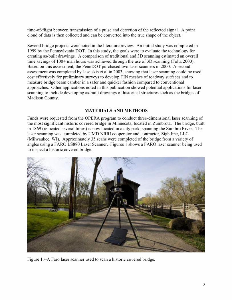
MATERIALS AND METHODS Funds were requested from the OPERA program to conduct three-dimensional laser scanning of the most significant historic covered bridge in Minnesota, located in Zumbrota. The bridge, built in 1869 (relocated several times) is now located in a city park, spanning the Zumbro River. The laser scanning was completed by UMD NRRI cooperator and contractor, Sightline, LLC (Milwaukee, WI). Approximately 35 scans were completed of the bridge from a variety of angles using a FARO LS880 Laser Scanner. Figures 1 shows a FARO laser scanner being used to inspect a historic covered bridge.
Figure 1.--A Faro laser scanner used to scan a historic covered bridge.

4
The scanning process consists of scans that were completed by Sightline and the processing of the data by UMD NRRI student engineer, Samuel Anderson. The following steps were completed and an estimate of the time duration provided for each step: 1. Paper "targets" are placed in numerous locations on the bridge for use in linking up to 40
individual laser scans together. Time duration: 2 person-hours. 2. A 3D Laser scanner (FARO Laser Scanner LS880) was used to conduct the scan. The
scanner is placed at several vantage points such that all visible surfaces of the bridge can be documented. When a single scan is completed, it is saved to a computer as an .ls file. Individual scans are completed in approximately 5 minutes. Time duration: 10 person-hours.
3. After all visible portions of the bridge have been scanned, the software files are linked using FARO Scene software. This software allows an individual to identify the targets placed prior to the scanning process and use them to link or attach one scan to another. The process of linking two individual scans is repeated several times until all scans have been compiled into one large scan depicting the entire bridge. Time duration: 9 person-hours.
4. Once a bridge has been completely assembled using all of the individual scans, it is exported as a point cloud, depicting all visible aspects of the bridge. This cloud of data is then exported into AutoCAD using an add-in provided by Kubit USA. This add-in allows a user to import point cloud files in addition to the ones inherently recognized by AutoCAD 2011 and has additional modeling tools for working directly with point cloud data in AutoCAD. Once a point cloud has been exported into AutoCAD, it is divided into multiple cross-sections. This is done so that specific components of the bridge can be seen more clearly. From this point, 2-D and 3-D models of the bridge can be generated. Time duration: 50-60 person-hours.
RESULTS
There are a number of types of images that can be presented from the processing of the point cloud data. Figures 2-13 show each different type of possible image that can be created using Faro Scene software or AutoCAD 2011 with a Kubit USA add-in. These images include a point cloud image resulting from only one scan, a parametric picture created from a point cloud scan, a point cloud image created from multiple scans, a point cloud image imbedded in AutoCAD, and 2D/3D AutoCAD images. All of the scan data, images and figures will also be provided to the City of Zumbrota for any further processing if necessary.

5
Figure 2.--A point cloud image from the Zumbrota bridge created from a single interior scan processed with Faro Scene software.
Figure 3A.--A point cloud image from the Zumbrota bridge created from a single exterior scan processed with Faro Scene software
6
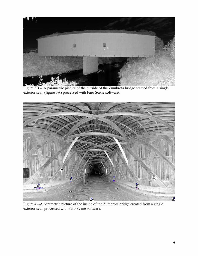
Figure 3B.-- A parametric picture of the outside of the Zumbrota bridge created from a single exterior scan (figure 3A) processed with Faro Scene software.
Figure 4.--A parametric picture of the inside of the Zumbrota bridge created from a single exterior scan processed with Faro Scene software.

7
Figure 5.--A point cloud image of the Zumbrota bridge created from multiple scans and linked together with Faro Scene software.

8
Figure 6.--A point cloud image of the Zumbrota bridge created from multiple scans and linked together with Faro Scene software.

9
Figure 7.--A point cloud image of the Zumbrota bridge created from multiple scans and linked together with Faro Scene software, imbedded into AutoCAD with a Kubit USA add-in.

10
Figure 8.--A point cloud image of the Zumbrota bridge created from multiple scans and linked together with Faro Scene software, imbedded into AutoCAD with a Kubit USA add-in.
Figure 9.--An AutoCAD 3D image of the Zumbrota bridge created from scanning data.

11
Figure 10.--An AutoCAD 2D image of the Zumbrota bridge created from scanning data.
12
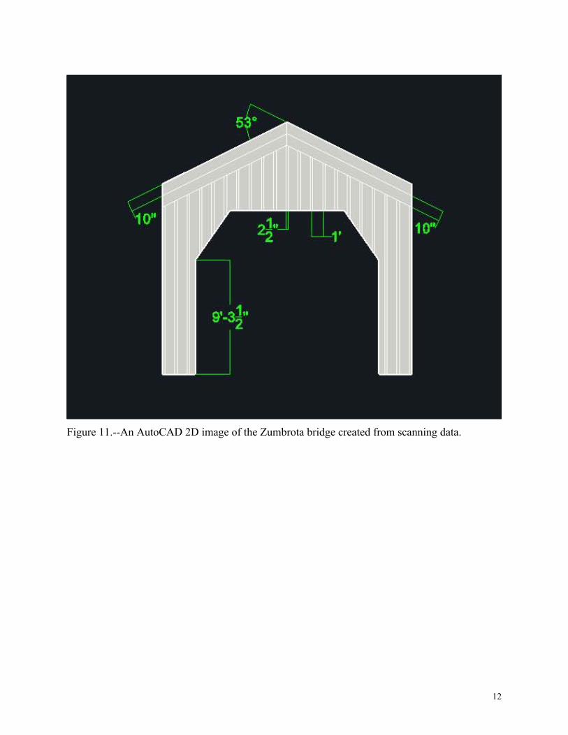
Figure 11.--An AutoCAD 2D image of the Zumbrota bridge created from scanning data.

13
Figure 12.--An AutoCAD 2D image of the Zumbrota bridge created from scanning data.

14
Figure 13.--Three AutoCAD 2D images (top 3) of wall components used to create a composite of the Zumbrota bridge wall.
15
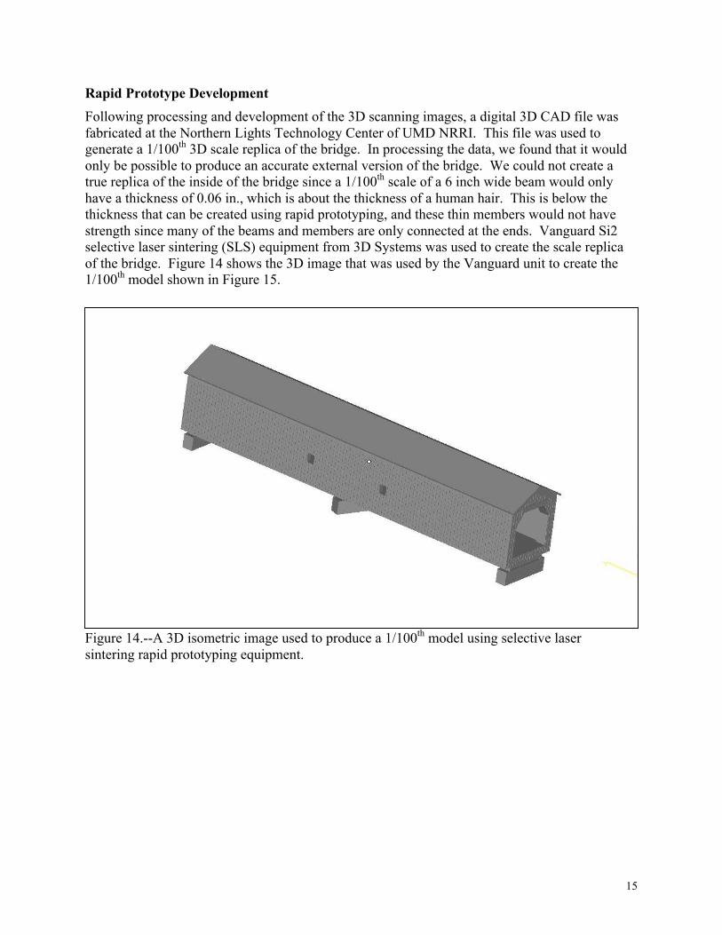
Rapid Prototype Development Following processing and development of the 3D scanning images, a digital 3D CAD file was fabricated at the Northern Lights Technology Center of UMD NRRI. This file was used to generate a 1/100th 3D scale replica of the bridge. In processing the data, we found that it would only be possible to produce an accurate external version of the bridge. We could not create a true replica of the inside of the bridge since a 1/100th scale of a 6 inch wide beam would only have a thickness of 0.06 in., which is about the thickness of a human hair. This is below the thickness that can be created using rapid prototyping, and these thin members would not have strength since many of the beams and members are only connected at the ends. Vanguard Si2 selective laser sintering (SLS) equipment from 3D Systems was used to create the scale replica of the bridge. Figure 14 shows the 3D image that was used by the Vanguard unit to create the 1/100th model shown in Figure 15.
Figure 14.--A 3D isometric image used to produce a 1/100th model using selective laser sintering rapid prototyping equipment.
16
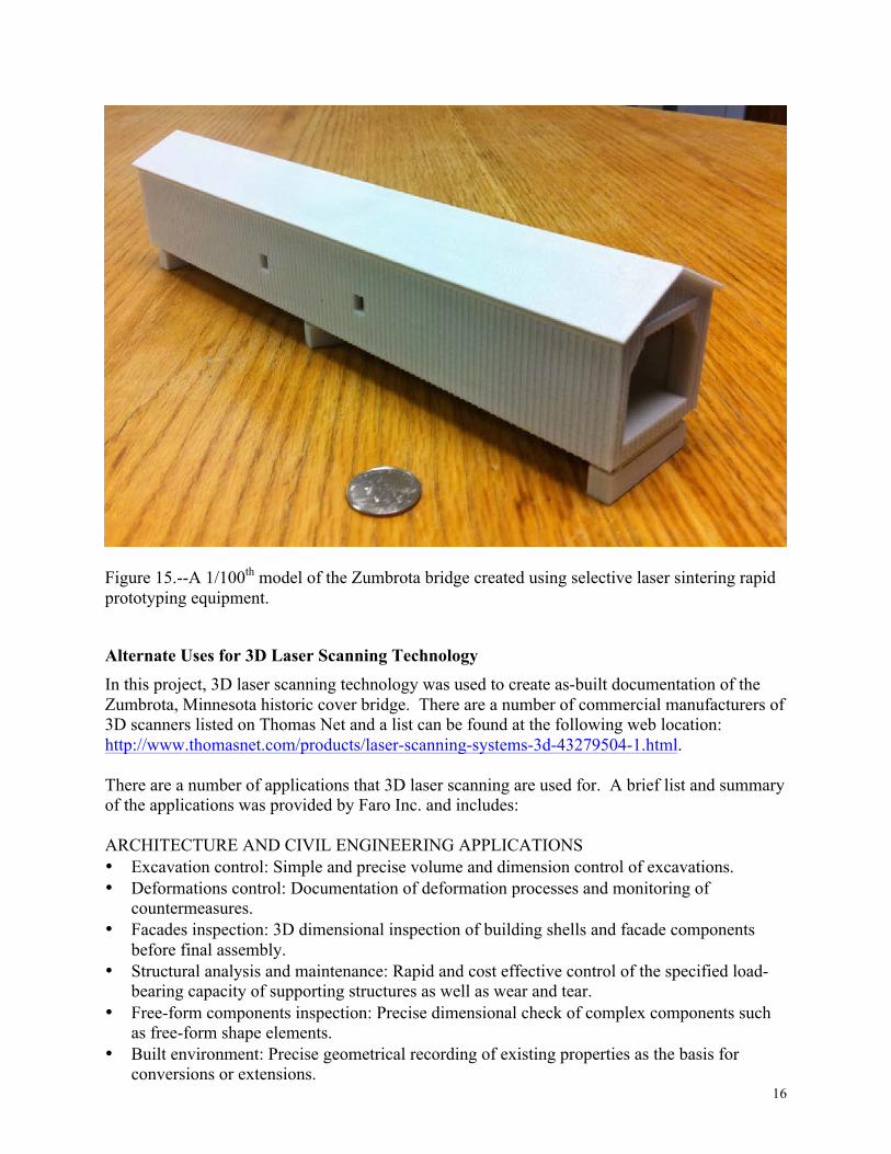
Figure 15.--A 1/100th model of the Zumbrota bridge created using selective laser sintering rapid prototyping equipment.
Alternate Uses for 3D Laser Scanning Technology In this project, 3D laser scanning technology was used to create as-built documentation of the Zumbrota, Minnesota historic cover bridge. There are a number of commercial manufacturers of 3D scanners listed on Thomas Net and a list can be found at the following web location: http://www.thomasnet.com/products/laser-scanning-systems-3d-43279504-1.html. There are a number of applications that 3D laser scanning are used for. A brief list and summary of the applications was provided by Faro Inc. and includes: ARCHITECTURE AND CIVIL ENGINEERING APPLICATIONS • Excavation control: Simple and precise volume and dimension control of excavations. • Deformations control: Documentation of deformation processes and monitoring of
countermeasures. • Facades inspection: 3D dimensional inspection of building shells and facade components
before final assembly. • Structural analysis and maintenance: Rapid and cost effective control of the specified load-
bearing capacity of supporting structures as well as wear and tear. • Free-form components inspection: Precise dimensional check of complex components such
as free-form shape elements. • Built environment: Precise geometrical recording of existing properties as the basis for
conversions or extensions.

17
• Construction progress monitoring: Seamless capture and monitoring of construction progress for legal and technical documentation.
PROCESS INDUSTRY AND DIGITAL FACTORY APPLICATIONS • Conversions and extensions: Precise 3D documentation of the current state of the property as
the planning basis for conversions and extensions. • Offsite production: Possibility of precise-fit off-site assembly, thanks to exact 3D CAD data
and dimensional control. • Asset management: Simplification of facility management, maintenance, training, etc.
through comprehensive 3D master data, simulations and training in virtual reality. • Site supervision: Improved coordination between different trades and comprehensive
documentation and supervision of all work. INSPECTION AND REVERSE ENGINEERING APPLICATIONS • Reverse engineering: Copies of products and components for which there are no construction
plans and/or CAD data available. • Interior fixtures and fittings: Precise 3D CAD documentation of complex interiors of ships,
cars or aircrafts as a basis for planning of conversions. • Manufacturing documentation: Complete 3D documentation of the manufacturing status of
complex machine components. • Quality control: Precise 3D documentation and dimensional inspection of large and complex
components such as rotor blades, turbines, ship propellers, etc. FORENSIC AND ACCIDENT SCENE APPLICATIONS • Rapid and complete 3D recordings of crime and accident scenes or insurance damage: All
details of relevance in any subsequent reconstruction of the crime or accident are covered. Similarly, in order to develop appropriate safety concepts for events, laser scans deliver the relevant 3D topography information.
HERITAGE APPLICATIONS • Complete and detailed documentation of historical structures or excavation sites: Whether
for restoration or scientific analysis purposes, for securing protected buildings or for virtual presentations of historical sites that must not be accessed by visitors.

18
ZUMBRO RIVER FLOOD 2010
On September 23-25, 2010, the Zumbro River flooded, creating a dangerous situation for the Zumbrota Covered Bridge. As Figures 16 and 17 show, floodwaters rose to nearly the same elevation as the bottom of the bridge. Additional river cresting could have caused substantial damage to the bridge, requiring the need for having as-built documentation, created during the scanning that took place in late July 2010. This is one very important example of the value of this project, creating new historical records should they be needed to repair or reconstruct a piece of Minnesota’s history. Please see the following article for additional details of our research project.
Figure 16.--Zumbrota covered bridge on September 23, 2010 during flooding on the Zumbro River (Photo courtesy of kstp.com).

19
Figure 17.--Zumbrota covered bridge on September 23, 2010 during flooding on the Zumbro River (Photo courtesy of fox9.com).

Sunrise over Lake Superior. NRRI receives U.S. EPA funding for Great Lakes Restoration Initiative research.
Autumn 2010
From the Director
Restoring the Great Lakes
Protecting plants
Future environmental leaders
Nurturing natural resources
Collaboration wins award
A better corn ethanol
Bridging the old with the new
~ G r o w i n g S t r o n g I n d u s t r i e s ~ D e v e l o p i n g N e w I d e a s ~ N u r t u r i n g N a t u r a l R e s o u r c e s
NRRI Now
Student employees 'work it'
Holding back the rain
You, too, can canoe
Welcoming Chancellor Black
2
3
6
7
8
10
10
11
12
14
15
16

When the Zumbro River crested at 22.8 feet in September, local residents actually felt a bit of relief. At least it didn’t reach the projected 28 feet that would have been a worse disaster for the town of Zumbrota, Minn.
Flooding in Goodhue County this summer was devastating to many businesses and homeowners, but another close call came when the swollen river just skimmed the bottom of the town’s historic covered bridge.
Had the water reached its projected crest, however, work by NRRI this summer would have proven invaluable. Into the future, the covered bridges of Madison County in Iowa and Minnesota’s one remaining covered bridge in Zumbrota are digitally imaged – down to the knot holes – and preserved for posterity.
Madison County has lost 13 of its original 19 covered bridges, built in the late 1880s – the last destroyed by arson in 2009. With no engineered drawings of the bridges, rebuilding from preserved pictures and inaccurate plans would require a lot of guesswork. The USDA Forest Products Laboratory contacted NRRI wood products Program Director Brian Brashaw to find a way to preserve the details of the remaining bridges.
Brashaw partnered with Faro Technologies, Inc. and SightLine, LLC to create computerized renderings using a 3-D laser scanning device that collects millions of points on any object. Each bridge took SightLine 6-8 hours to gather the raw scan data. NRRI intern Sam Anderson could then process the data into a digital “point cloud” (see photo above) and AutoCAD images.
“This is a great demonstration of the potential of this equipment,” said Brashaw. “The bridges are a big tourist draw to these rural areas. And there are other new opportunities. We can figure out how to apply this technology to manufacturing plants, measure volumes of forest stands, or gather accurate landscape measurements for stream remediation projects.”
After completing 30-plus scans on each bridge, each one is photographed, tape-measured and the information is processed with unique software provided by kubitUSA. The digital files are then sent to the USDA Forest Products Lab. With the Zumbrota bridge records, a 1/100th scale replica built in NRRI’s rapid prototyping center was also included. The digital collection will eventually be added to the Library of Congress and each community will receive detailed information for their historical archives.
“We enjoyed working on this project with NRRI,” said SightLine President Penny Anstey. “The bridges are important to the economy and history of these communities. And this is what we got into this business for, to preserve history.”
Historic bridges are
preserved with laser
technologies
Bridging the old with the new
11
Cutler-Donahue bridge in Madison County, Iowa. Digital point cloud image.