user guide types 8185, 8186, 8187, 8188, 8189 types8190...
TRANSCRIPT

ThinkCentre™
User GuideTypes 8185, 8186, 8187, 8188, 8189Types 8190, 8192, 8193, 8194, 8195Types 8196, 8197, 8432, 8433
���


ThinkCentre™
User GuideTypes 8185, 8186, 8187, 8188, 8189Types 8190, 8192, 8193, 8194, 8195Types 8196, 8197, 8432, 8433
���

NoteBefore using this information and the product it supports, be sure to read the “Safety Information” on page v andAppendix E, “Notices”, on page 117.
Second Edition (May 2003)
© Copyright International Business Machines Corporation 2003. All rights reserved.US Government Users Restricted Rights – Use, duplication or disclosure restricted by GSA ADP Schedule Contractwith IBM Corp.
Contents
Safety Information . . . . . . . . . . vLithium battery notice . . . . . . . . . . . viModem safety information . . . . . . . . . viLaser compliance statement . . . . . . . . . vii
Overview . . . . . . . . . . . . . . ixInformation resources . . . . . . . . . . . ixAccess IBM Predesktop Area . . . . . . . . . ixIdentifying your computer. . . . . . . . . . x
Chapter 1. Types 8185, 8186, and 8192 . 1Features . . . . . . . . . . . . . . . . 1Specifications . . . . . . . . . . . . . . 4Available options . . . . . . . . . . . . . 5Tools required . . . . . . . . . . . . . . 5Handling static-sensitive devices. . . . . . . . 5Installing external options . . . . . . . . . . 6
Locating the connectors on the front of yourcomputer . . . . . . . . . . . . . . 6Locating the connectors on the rear of yourcomputer . . . . . . . . . . . . . . 7Obtaining device drivers . . . . . . . . . 8
Removing the cover . . . . . . . . . . . . 9Locating components . . . . . . . . . . . 10Identifying parts on the system board . . . . . 10Installing memory . . . . . . . . . . . . 11Installing adapters . . . . . . . . . . . . 12Installing internal drives . . . . . . . . . . 14
Drive specifications . . . . . . . . . . . 14Installing a CD-ROM or DVD-ROM drive . . . 15
Installing security features . . . . . . . . . 17Identifying security locks . . . . . . . . . 17Rope clip . . . . . . . . . . . . . . 17Integrated cable lock . . . . . . . . . . 19Password protection . . . . . . . . . . 19
Changing the battery . . . . . . . . . . . 19Erasing a lost or forgotten password (clearingCMOS) . . . . . . . . . . . . . . . . 20Replacing the cover and connecting the cables. . . 21
Chapter 2. Types 8187, 8188, and 8193 23Features . . . . . . . . . . . . . . . 23Specifications . . . . . . . . . . . . . . 26Available options . . . . . . . . . . . . 27Tools required . . . . . . . . . . . . . 27Handling static-sensitive devices . . . . . . . 27Installing external options . . . . . . . . . 28
Locating the connectors on the front of yourcomputer . . . . . . . . . . . . . . 28Locating the connectors on the rear of yourcomputer . . . . . . . . . . . . . . 29Obtaining device drivers . . . . . . . . . 30
Removing the cover . . . . . . . . . . . 31Locating components . . . . . . . . . . . 32Identifying parts on the system board . . . . . 32
Installing memory . . . . . . . . . . . . 33Installing adapters . . . . . . . . . . . . 34Installing internal drives . . . . . . . . . . 36
Drive specifications . . . . . . . . . . . 36Installing a drive . . . . . . . . . . . 37
Installing security features . . . . . . . . . 40Identifying security locks . . . . . . . . . 41Rope clip . . . . . . . . . . . . . . 41Integrated cable lock . . . . . . . . . . 43Password protection . . . . . . . . . . 43
Changing the battery . . . . . . . . . . . 43Erasing a lost or forgotten password (clearingCMOS) . . . . . . . . . . . . . . . . 44Replacing the cover and connecting the cables. . . 45
Chapter 3. Types 8196 and 8197 . . . . 47Features . . . . . . . . . . . . . . . 47Specifications . . . . . . . . . . . . . . 50Available options . . . . . . . . . . . . 51Tools required . . . . . . . . . . . . . 51Handling static-sensitive devices . . . . . . . 51Installing external options . . . . . . . . . 52
Locating the connectors on the front of yourcomputer . . . . . . . . . . . . . . 53Locating the connectors on the rear of yourcomputer . . . . . . . . . . . . . . 54Obtaining device drivers . . . . . . . . . 55
Removing the cover . . . . . . . . . . . 56Locating components . . . . . . . . . . . 57Identifying parts on the system board . . . . . 57Installing memory . . . . . . . . . . . . 58Installing adapters . . . . . . . . . . . . 60Installing internal drives . . . . . . . . . . 61
Drive specifications . . . . . . . . . . . 62Installing a drive . . . . . . . . . . . 62
Installing security features . . . . . . . . . 65Identifying security locks . . . . . . . . . 66Rope clip . . . . . . . . . . . . . . 66Integrated cable lock . . . . . . . . . . 68Password protection . . . . . . . . . . 68
Changing the battery . . . . . . . . . . . 68Erasing a lost or forgotten password (clearingCMOS) . . . . . . . . . . . . . . . . 69Replacing the cover and connecting the cables. . . 70
Chapter 4. Types 8189, 8190, 8194,8195, 8432, and 8433. . . . . . . . . 73Features . . . . . . . . . . . . . . . 73Specifications . . . . . . . . . . . . . . 76Available options . . . . . . . . . . . . 77Tools required . . . . . . . . . . . . . 77Handling static-sensitive devices . . . . . . . 77Installing external options . . . . . . . . . 78
Locating the connectors on the front of yourcomputer . . . . . . . . . . . . . . 79
© Copyright IBM Corp. 2003 iii
Locating the connectors on the rear of yourcomputer . . . . . . . . . . . . . . 80Obtaining device drivers . . . . . . . . . 81
Removing the cover . . . . . . . . . . . 82Locating components . . . . . . . . . . . 83Identifying parts on the system board . . . . . 83Installing memory . . . . . . . . . . . . 84Installing adapters . . . . . . . . . . . . 85Installing internal drives . . . . . . . . . . 87
Drive specifications . . . . . . . . . . . 87Installing a drive . . . . . . . . . . . 88
Installing security features . . . . . . . . . 91Identifying security locks . . . . . . . . . 92Rope clip . . . . . . . . . . . . . . 92Integrated cable lock . . . . . . . . . . 94Password protection . . . . . . . . . . 94
Changing the battery . . . . . . . . . . . 94Erasing a lost or forgotten password (clearingCMOS) . . . . . . . . . . . . . . . . 95Replacing the cover and connecting the cables. . . 96
Chapter 5. Using the IBM Setup Utilityprogram . . . . . . . . . . . . . . 99Starting the IBM Setup Utility program . . . . . 99Viewing and changing settings . . . . . . . . 99Exiting from the IBM Setup Utility program . . . 99Using passwords . . . . . . . . . . . . 99
User password . . . . . . . . . . . . 100Administrator password. . . . . . . . . 100Setting, changing, and deleting a password . . 100
Security settings for Access IBM Predesktop Area 100Using Security Profile by Device . . . . . . . 101Using IDE Drives Setup . . . . . . . . . . 101Selecting a startup device . . . . . . . . . 102
Selecting a temporary startup device . . . . 102
Changing the startup sequence . . . . . . 102Advanced settings . . . . . . . . . . . . 102
Appendix A. Updating systemprograms . . . . . . . . . . . . . 103System programs . . . . . . . . . . . . 103
Updating (flashing) BIOS from a diskette . . . 103Updating (flashing) BIOS from your operatingsystem . . . . . . . . . . . . . . 103
Recovering from a POST/BIOS update failure . . 104
Appendix B. Cleaning the mouse . . . 105Cleaning an optical mouse . . . . . . . . . 105Cleaning a mouse with a ball . . . . . . . . 105
Appendix C. Manual modemcommands . . . . . . . . . . . . 107Basic AT commands . . . . . . . . . . . 107Extended AT commands. . . . . . . . . . 109MNP/V.42/V.42bis/V.44 commands . . . . . . 110Fax Class 1 commands . . . . . . . . . . 111Fax Class 2 commands . . . . . . . . . . 111Voice commands . . . . . . . . . . . . 112
Appendix D. Customer replaceableunit (CRU) parts list. . . . . . . . . 115
Appendix E. Notices . . . . . . . . 117Television output notice . . . . . . . . . . 118Trademarks . . . . . . . . . . . . . . 118
Index . . . . . . . . . . . . . . . 119
iv User Guide

Safety Information
DANGER
Electrical current from power, telephone, and communication cables ishazardous.
To avoid a shock hazard:
v Do not connect or disconnect any cables or perform installation, maintenance,or reconfiguration of this product during an electrical storm.
v Connect all power cords to a properly wired and grounded electrical outlet.
v Connect to properly wired outlets any equipment that will be attached to thisproduct.
v When possible, use one hand only to connect or disconnect signal cables.
v Never turn on any equipment when there is evidence of fire, water, orstructural damage.
v Disconnect the attached power cords, telecommunications systems, networks,and modems before you open the device covers, unless instructed otherwisein the installation and configuration procedures.
v Connect and disconnect cables as described in the following table wheninstalling, moving, or opening covers on this product or attached devices.
To connect:
1. Turn everything OFF.
2. First, attach all cables to devices.
3. Attach signal cables to connectors.
4. Attach power cords to outlet.
5. Turn device ON.
To disconnect:
1. Turn everything OFF.
2. First, remove power cords from outlet.
3. Remove signal cables from connectors.
4. Remove all cables from devices.
DANGER
Le courant électrique provenant de l’alimentation, du téléphone et des câbles detransmission peut présenter un danger.
Pour éviter tout risque de choc électrique :
v Ne manipulez aucun câble et n’effectuez aucune opération d’installation,d’entretien ou de reconfiguration de ce produit au cours d’un orage.
v Branchez tous les cordons d’alimentation sur un socle de prise de courantcorrectement câblé et mis à la terre.
v Branchez sur des socles de prise de courant correctement câblés toutéquipement connecté à ce produit.
v Lorsque cela est possible, n’utilisez qu’une seule main pour connecter oudéconnecter les câbles d’interface.;
v Ne mettez jamais un équipement sous tension en cas d’incendie oud’inondation, ou en présence de dommages matériels.
v Avant de retirer les carters de l’unité, mettez celle-ci hors tension etdéconnectez ses cordons d’alimentation, ainsi que les câbles qui la relient aux
© Copyright IBM Corp. 2003 v
réseaux, aux systèmes de té lécommunication et aux modems (sauf instructioncontraire mentionnée dans les procédures d’installation et de configuration).
v Lorsque vous installez, que vous déplacez, ou que vous manipulez le présentproduit ou des périphériques qui lui sont raccordés, reportez-vous auxinstructions ci-dessous pour connecter et déconnecter les différents cordons.
Connexion:
1. Mettez les unités hors tension.
2. Commencez par brancher tous lescordons sur les unités.
3. Branchez les câbles d’interface sur desconnecteurs.
4. Branchez les cordons d’alimentation surdes prises.
5. Mettez les unités sous tension.
Déconnexion:
1. Mettez les unités hors tension.
2. Débranchez les cordons d’alimentationdes prises.
3. Débranchez les câbles d’interface desconnecteurs.
4. Débranchez tous les câbles des unités.
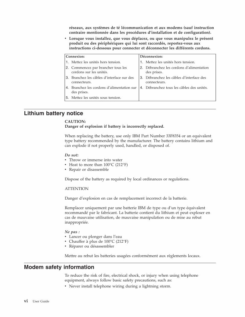
Lithium battery noticeCAUTION:Danger of explosion if battery is incorrectly replaced.
When replacing the battery, use only IBM Part Number 33F8354 or an equivalenttype battery recommended by the manufacturer. The battery contains lithium andcan explode if not properly used, handled, or disposed of.
Do not:v Throw or immerse into waterv Heat to more than 100°C (212°F)v Repair or disassemble
Dispose of the battery as required by local ordinances or regulations.
ATTENTION
Danger d’explosion en cas de remplacement incorrect de la batterie.
Remplacer uniquement par une batterie IBM de type ou d’un type équivalentrecommandé par le fabricant. La batterie contient du lithium et peut exploser encas de mauvaise utilisation, de mauvaise manipulation ou de mise au rebutinappropriée.
Ne pas :v Lancer ou plonger dans l’eauv Chauffer à plus de 100°C (212°F)v Réparer ou désassembler
Mettre au rebut les batteries usagées conformément aux règlements locaux.
Modem safety informationTo reduce the risk of fire, electrical shock, or injury when using telephoneequipment, always follow basic safety precautions, such as:v Never install telephone wiring during a lightning storm.
vi User Guide

v Never install telephone jacks in wet locations unless the jack is specificallydesigned for wet locations.
v Never touch uninsulated telephone wires or terminals unless the telephone linehas been disconnected at the network interface.
v Use caution when installing or modifying telephone lines.v Avoid using a telephone (other than a cordless type) during an electrical storm.
There may be a remote risk of electric shock from lightning.v Do not use the telephone to report a gas leak in the vicinity of the leak.
Consignes de sécurité relatives au modem
Lors de l’utilisation de votre matériel téléphonique, il est important de respecter lesconsignes ci-après afin de réduire les risques d’incendie, d’électrocution et d’autresblessures :v N’installez jamais de cordons téléphoniques durant un orage.v Les prises téléphoniques ne doivent pas être installées dans des endroits
humides, excepté si le modèle a été conçu à cet effet.v Ne touchez jamais un cordon téléphonique ou un terminal non isolé avant que
la ligne ait été déconnectée du réseau téléphonique.v Soyez toujours prudent lorsque vous procédez à l’installation ou à la
modification de lignes téléphoniques.v Si vous devez téléphoner pendant un orage, pour éviter tout risque de choc
électrique, utilisez toujours un téléphone sans fil.v En cas de fuite de gaz, n’utilisez jamais un téléphone situé à proximité de la
fuite.
Laser compliance statementSome IBM Personal Computer models are equipped from the factory with aCD-ROM drive or a DVD-ROM drive. CD-ROM drives and DVD-ROM drives arealso sold separately as options. CD-ROM drives and DVD-ROM drives are laserproducts. These drives are certified in the U.S. to conform to the requirements ofthe Department of Health and Human Services 21 Code of Federal Regulations(DHHS 21 CFR) Subchapter J for Class 1 laser products. Elsewhere, these drivesare certified to conform to the requirements of the International ElectrotechnicalCommission (IEC) 825 and CENELEC EN 60 825 for Class 1 laser products.
When a CD-ROM drive or a DVD-ROM drive is installed, note the followinghandling instructions.
CAUTION:Use of controls or adjustments or performance of procedures other than thosespecified herein might result in hazardous radiation exposure.
Removing the covers of the CD-ROM drive or DVD-ROM drive could result inexposure to hazardous laser radiation. There are no serviceable parts inside theCD-ROM drive or DVD-ROM drive. Do not remove the drive covers.
Some CD-ROM drives and DVD-ROM drives contain an embedded Class 3A orClass 3B laser diode. Note the following statement.
Safety Information vii

DANGER
Laser radiation when open. Do not stare into the beam, do not view directly with opticalinstruments, and avoid direct exposure to the beam.
DANGER:
Certains modèles d’ordinateurs personnels sont équipés d’origine d’une unité deCD-ROM ou de DVD-ROM. Mais ces unités sont également vendues séparémenten tant qu’options. L’unité de CD-ROM/DVD-ROM est un appareil à laser. AuxÉtat-Unis, l’unité de CD-ROM/DVD-ROM est certifiée conforme aux normesindiquées dans le sous-chapitre J du DHHS 21 CFR relatif aux produits à laser declasse 1. Dans les autres pays, elle est certifiée être un produit à laser de classe 1conforme aux normes CEI 825 et CENELEC EN 60 825.
Lorsqu’une unité de CD-ROM/DVD-ROM est installée, tenez compte desremarques suivantes:
ATTENTION: Pour éviter tout risque d’exposition au rayon laser, respectez lesconsignes de réglage et d’utilisation des commandes, ainsi que les procéduresdécrites.
L’ouverture de l’unité de CD-ROM/DVD-ROM peut entraîner un risqued’exposition au rayon laser. Pour toute intervention, faites appel à du personnelqualifié.
Certaines unités de CD-ROM/DVD-ROM peuvent contenir une diode à laser declasse 3A ou 3B. Tenez compte de la consigne qui suit:
DANGER
Rayonnement laser lorsque le carter est ouvert. Évitez toute exposition directe des yeuxau rayon laser. Évitez de regarder fixement le faisceau ou de l’observer à l’aided’instruments optiques.
viii User Guide
Overview
Thank you for selecting an IBM® computer. Your computer incorporates many ofthe latest advances in computer technology and can be upgraded as your needschange.
This publication supports several computer models. Information in this section willhelp you identify your computer and help you find the chapter that containsinformation specific to your computer.
Adding hardware options to your computer is an easy way to increase itscapabilities. Instructions for installing external and internal options are included inthis publication. When adding an option, use these instructions along with theinstructions that come along with the option.
Information resourcesThe Quick Reference that comes with your computer provides information forinstalling your computer and starting the operating system. It also includes basictroubleshooting information, software recovery procedures, help and serviceinformation, and warranty information.
Access IBM, on your desktop, provides a link to more information about yourcomputer.
If you have Internet access, the most up-to-date manuals for your computer areavailable from the World Wide Web. To access this information, point your browserto
http://www.ibm.com/pc/support
Type your machine type and model number in the Quick Path field, and click Go.
Access IBM Predesktop AreaThe Access IBM Predesktop Area is a launching area of a number of tools designedto run independently of the Windows® operating system. The Access IBMPredesktop Area provides an easy-to-use environment to help you diagnoseproblems and recover from problems that might otherwise leave your computer ina nonfunctional state.
To open the Access IBM Predesktop Area, do the following:1. If your computer is already on when you start this procedure, shut down the
operating system and turn off the computer.2. Turn on the computer and look for the following prompt on the logo screen:
(To interrupt normal startup, press Enter)
Press Enter when you see this prompt.3. The Access IBM Predesktop Area displays.
© Copyright IBM Corp. 2003 ix
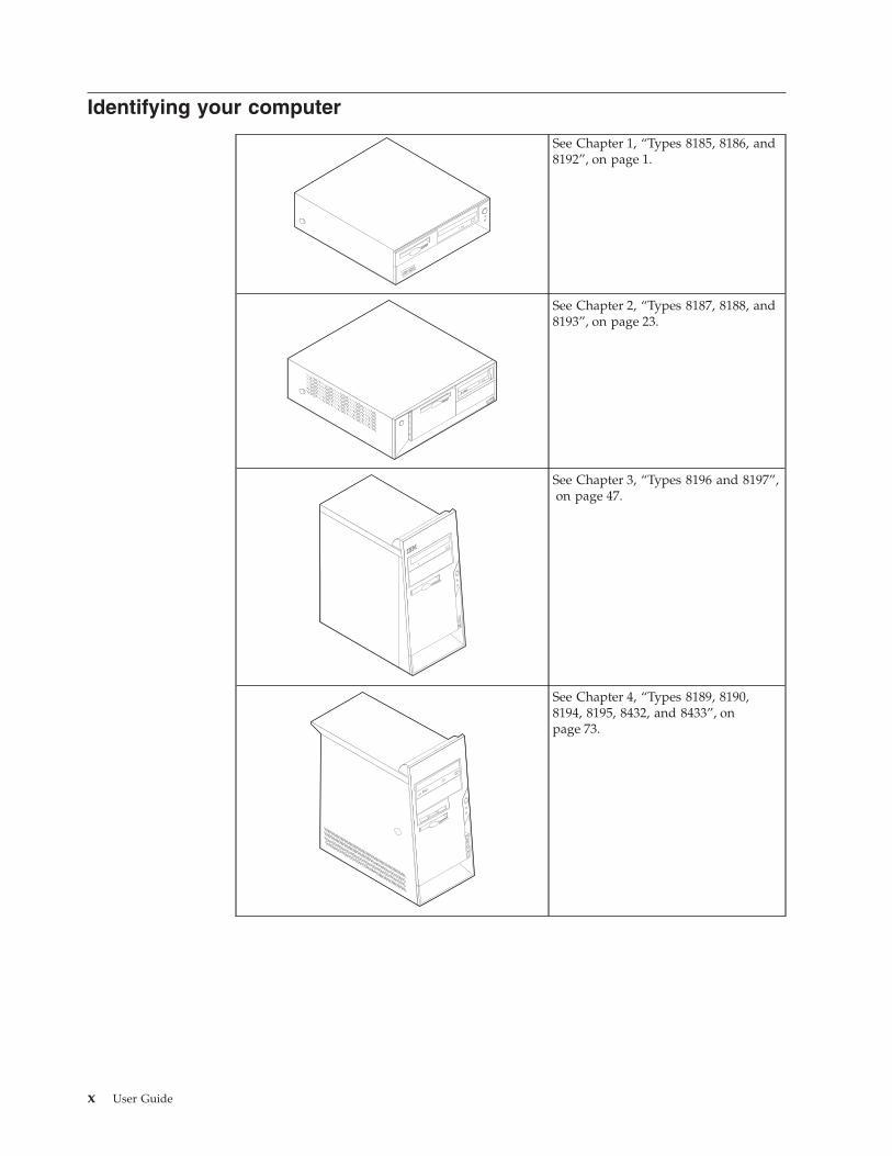
Identifying your computer
See Chapter 1, “Types 8185, 8186, and8192”, on page 1.
See Chapter 2, “Types 8187, 8188, and8193”, on page 23.
See Chapter 3, “Types 8196 and 8197”,on page 47.
See Chapter 4, “Types 8189, 8190,8194, 8195, 8432, and 8433”, onpage 73.
x User Guide

Chapter 1. Types 8185, 8186, and 8192
This chapter provides an introduction to the features and options that are availablefor your computer. You can expand the capabilities of your computer by addingmemory, adapters, or drives. When installing an option, use these instructionsalong with the instructions that come with the option.
ImportantBefore you install or remove any option, read “Safety Information” on page v.These precautions and guidelines will help you work safely.
FeaturesThis section provides an overview of the computer features and preinstalledsoftware.
System informationThe following information covers a variety of models. For a listing of thefeatures for your specific model, click Information in the Access IBMPredesktop Area. See “Access IBM Predesktop Area” on page ix.
Microprocessor (varies by model type)v Intel® Pentium® 4 processor with 512 KB of internal L2 cache memory and Intel
NetBurst™ micro-architecturev Intel Celeron® processor with 128 KB of internal L2 cache memory
Memory
v Support for four dual inline memory modules (DIMMs)v 512 KB flash memory for system programs
Internal drives
v 3.5-inch, 1.44 MB diskette drivev Internal hard disk drivev EIDE CD-ROM drive or DVD-ROM drive (some models)
© Copyright IBM Corp. 2003 1

Video subsystem
v An integrated graphics controller for a Video Graphics Array (VGA) monitorv Accelerated graphics port (AGP) video adapter slot on the system board
Audio subsystem
v AC’97 with ADI 1981B Audio Codecv Line in, line out, and microphone connectors on the rear panel
Connectivity
v 10/100 Mbps integrated Intel Ethernet controller that supports the Wake onLAN® feature (some models)
v 10/100/1000 Mbps integrated Intel Ethernet controller that supports the Wakeon LAN feature (some models)
v Soft modem V.90/V.44 (some models)
System management features
v Remote Program Load (RPL) and Dynamic Host Configuration Protocol (DHCP)v Wake on LANv Wake on Ring (in the IBM Setup Utility program, this feature is called Serial Port
Ring Detect for an external modem)v Remote Administrationv Automatic power-on startupv System Management (SM) BIOS and SM softwarev Ability to store POST hardware test results
Input/output features
v 25-pin, Extended Capabilities Port (ECP)/Extended Parallel Port (EPP)v 9-pin serial connectorv Eight 4-pin, USB connectors (two on front panel and six on rear panel)v PS/2® mouse connectorv PS/2 keyboard connectorv Ethernet connectorv VGA monitor connectorv Three audio connectors (line in, line out, and microphone)v Front connectors for microphone and headphone (some models)
Expansion
v Three drive baysv Three 32-bit peripheral component interconnect (PCI) adapter slots (supports
low-profile adapters only)v One accelerated graphics port (AGP) expansion slot (supports low-profile
adapters only)
Power
v 200 W power supply with manual voltage selection switchv Automatic 50/60 Hz input frequency switchingv Advanced Power Management supportv Advanced Configuration and Power Interface (ACPI) support
2 User Guide

Security features
v User and administrator passwordsv Support for the addition of a rope clip and lockable cablev Support for the addition of an integrated cable lockv Startup sequence controlv Startup without diskette drive, keyboard, or mousev Unattended start modev Diskette and hard disk I/O controlv Serial and parallel port I/O controlv Security profile by device
IBM preinstalled softwareYour computer might come with preinstalled software. If it does, an operatingsystem, device drivers to support built-in features, and other support programs areincluded.
Operating systems (preinstalled) (varies by model type)
Note: Not all countries or regions will have these operating systems.v Microsoft® Windows XP Homev Microsoft Windows XP Professionalv Microsoft Windows 2000
Operating systems (tested for compatibility)1
v Microsoft Windows NT® Workstation Version 4.0v Microsoft Windows 98 Second Edition
1. The operating systems listed here are being tested for compatibility at the time this publication goes to press. Additionaloperating systems might be identified by IBM as compatible with your computer following the publication of this booklet.Corrections and additions to this list are subject to change. To determine if an operating system has been tested for compatibility,check the Web site of the operating system vendor.
Chapter 1. Types 8185, 8186, and 8192 3
SpecificationsThis section lists the physical specifications for your computer.
Dimensions
Height: 104 mm (4.1 in.)
Width: 360 mm (14.2 in.)
Depth: 412 mm (16.2 in.)
Weight
Minimum configuration as shipped: 8.1 kg (18 lb)
Maximum configuration: 9.1 kg (20 lb)
Environment
Air temperature:
System on: 10° to 35°C (50° to 95° F)System off: 10° to 43°C (50° to 110° F)
Maximum altitude: 2134 m (7000 ft)Note: The maximum altitude, 2134 m (7000 ft),is the maximum altitude at which the specifiedair temperatures apply. At higher altitudes, themaximum air temperatures are lower than thosespecified.
Humidity:
System on: 8% to 80%
System off: 8% to 80%
Electrical input
Input voltage:
Low range:
Minimum: 90 V ac
Maximum: 180 V ac
Input frequency range: 47–53 Hz
Voltage switch setting: 115 V ac
High range:
Minimum: 137 V ac
Maximum: 265 V ac
Input frequency range: 57–63 Hz
Voltage switch setting: 230 V ac
Input kilovolt-amperes (kVA) (approximate):
Minimum configuration as shipped: 0.08 kVA
Maximum configuration: 0.25 kVA
Note: Power consumption and heat output varydepending on the number and type of optionalfeatures installed and the power-managementoptional features in use.
Heat output (approximate) in British thermal units (Btu)per hour:
Minimum configuration: 257 Btu/hr (75 watts)
Maximum configuration: 683 Btu/hr (200 watts)
Airflow
Approximately 0.45 cubic meters per minute (16 cubicfeet per minute) maximum
Acoustical noise-emission values
For microprocessors less than 2.8 GHz:
Average sound-pressure levels:
At operator position:
Idle: 28 dBA
Operating: 30 dBA
At bystander position - 1 meter (3.3 ft):
Idle: 27 dBA
Operating: 29 dBA
Declared (upper limit) sound-power levels:
Idle: 4.2 bels
Operating: 4.3 bels
For microprocessors greater than or equal to 2.8 GHz:
Average sound-pressure levels:
At operator position:
Idle: 29 dBA
Operating: 31 dBA
At bystander position - 1 meter (3.3 ft):
Idle: 28 dBA
Operating: 29 dBA
Declared (upper limit) sound-power levels:
Idle: 4.3 bels
Operating: 4.4 bels
Note: These levels were measured in controlled acousticalenvironments according to the procedures specified by theAmerican National Standards Institute (ANSI) S12.10 andISO 7779 and are reported in accordance with ISO 9296.Actual sound-pressure levels in a given location mightexceed the average values stated because of roomreflections and other nearby noise sources. The declaredsound-power levels indicate an upper limit, below which alarge number of computers will operate.
4 User Guide

Available optionsThe following are some available options:v External options
– Parallel port devices, such as printers and external drives– Serial port devices, such as external modems and digital cameras– Audio devices, such as external speakers for the sound system– USB devices, such as printers, joysticks, and scanners– Security device, such as a rope clip– Monitors
v Internal options– System memory, called dual inline memory modules (DIMMs)– Peripheral component interconnect (PCI) adapters (supports low-profile
adapters only)– Accelerated graphics port (AGP) adapters (supports low-profile adapters
only)– Internal drives, such as:
- CD-ROM drive and DVD-ROM drive (some models)- Hard disk drive- Diskette drives and other removable media drives
For the latest information about available options, see the following World WideWeb pages:v http://www.ibm.com/pc/us/options/v http://www.ibm.com/pc/support/
You can also obtain information by calling the following telephone numbers:v Within the United States, call 1-800-IBM-2YOU (1-800-426-2968), your IBM
reseller, or IBM marketing representative.v Within Canada, call 1-800-565-3344 or 1-800-IBM-4YOU.v Outside the United States and Canada, contact your IBM reseller or IBM
marketing representative.
Tools requiredTo install some options in your computer, you might need a flat-blade or Phillipsscrewdriver. Additional tools might be needed for certain options. See theinstructions that come with the option.
Handling static-sensitive devicesStatic electricity, although harmless to you, can seriously damage computercomponents and options.
When you add an option, do not open the static-protective package containing theoption until you are instructed to do so.
When you handle options and other computer components, take these precautionsto avoid static electricity damage:v Limit your movement. Movement can cause static electricity to build up around
you.
Chapter 1. Types 8185, 8186, and 8192 5
v Always handle components carefully. Handle adapters and memory modules bythe edges. Never touch any exposed circuitry.
v Prevent others from touching components.v When you install a new option, touch the static-protective package containing
the option to a metal expansion-slot cover or other unpainted metal surface onthe computer for at least two seconds. This reduces static electricity in thepackage and your body.
v When possible, remove the option and install it directly in the computer withoutsetting the option down. When this is not possible, place the static-protectivepackage that the option came in on a smooth, level surface and place the optionon it.
v Do not place the option on the computer cover or other metal surface.
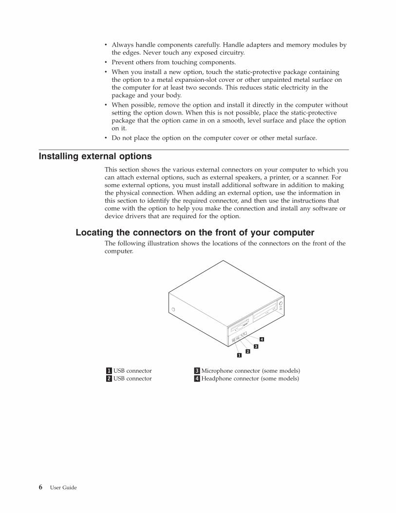
Installing external optionsThis section shows the various external connectors on your computer to which youcan attach external options, such as external speakers, a printer, or a scanner. Forsome external options, you must install additional software in addition to makingthe physical connection. When adding an external option, use the information inthis section to identify the required connector, and then use the instructions thatcome with the option to help you make the connection and install any software ordevice drivers that are required for the option.
Locating the connectors on the front of your computerThe following illustration shows the locations of the connectors on the front of thecomputer.
�1�USB connector �3�Microphone connector (some models)�2�USB connector �4�Headphone connector (some models)
6 User Guide

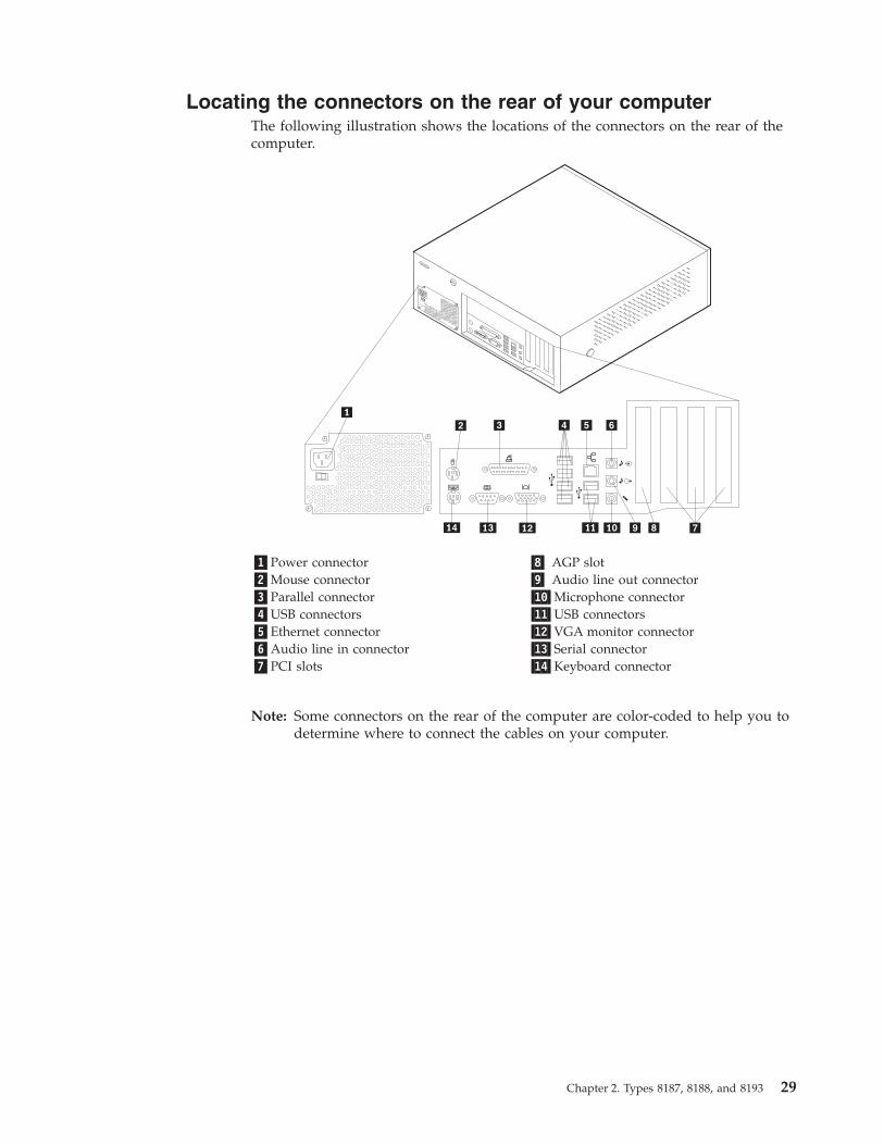
Locating the connectors on the rear of your computerThe following illustration shows the locations of the connectors on the rear of thecomputer.
�1�Mouse connector �8� AGP slot�2�Parallel connector �9� Audio line out connector�3�USB connectors �10�Microphone connector�4�Ethernet connector �11�USB connectors�5�Audio line in connector �12�VGA monitor connector�6�Power connector �13�Serial connector�7�PCI slots �14�Keyboard connector
Note: Some connectors on the rear of the computer are color-coded to help you todetermine where to connect the cables on your computer.
Chapter 1. Types 8185, 8186, and 8192 7

Connector Description
Mouse connector Used to attach a mouse, trackball, or other pointing device thatuses a standard mouse connector.
Parallel connector Used to attach a parallel printer, parallel scanner, or otherdevices that use a 25-pin parallel connector.
USB connectors Used to attach a device that requires a Universal Serial Bus(USB) connection, such as a USB scanner or USB printer. If youhave more than eight USB devices, you can purchase a USBhub, which you can use to connect additional USB devices.
Ethernet connector Used to attach an Ethernet cable for a local area network(LAN).Note: To operate the computer within FCC Class B limits, usea Category 5 Ethernet cable.
Audio line in connector Used to receive audio signals from an external audio device,such as a stereo system. When you attach an external audiodevice, a cable is connected between the audio line outconnector of the device and the audio line in connector of thecomputer.
Audio line out connector Used to send audio signals from the computer to externaldevices, such as powered stereo speakers (speakers withbuilt-in amplifiers), headphones, multimedia keyboards, or theaudio line in connector on a stereo system or other externalrecording device.
Microphone connector Used to attach a microphone to your computer when you wantto record voice or other sounds on the hard disk if you usespeech-recognition software.
Serial connector Used to attach an external modem, serial printer, or otherdevices that use a 9-pin serial connector.
Keyboard connector Used to attach a keyboard that uses a standard keyboardconnector.
Obtaining device driversYou can obtain device drivers for operating systems that are not preinstalled athttp://www.ibm.com/pc/support/ on the World Wide Web. Installationinstructions are provided in README files with the device-driver files.
8 User Guide

Removing the cover
ImportantRead “Safety Information” on page v and “Handling static-sensitive devices”on page 5 before removing the cover.
To remove the cover:1. Shut down your operating system, remove any media (diskettes, CDs, or tapes)
from the drives, and turn off all attached devices and the computer.2. Unplug all power cords from electrical outlets.3. Disconnect all cables attached to the computer. This includes power cords,
input/output (I/O) cables, and any other cables that are connected to thecomputer.
4. Press the buttons on the sides of the computer and pivot the rear end of thecover up toward the front of the computer.
Chapter 1. Types 8185, 8186, and 8192 9
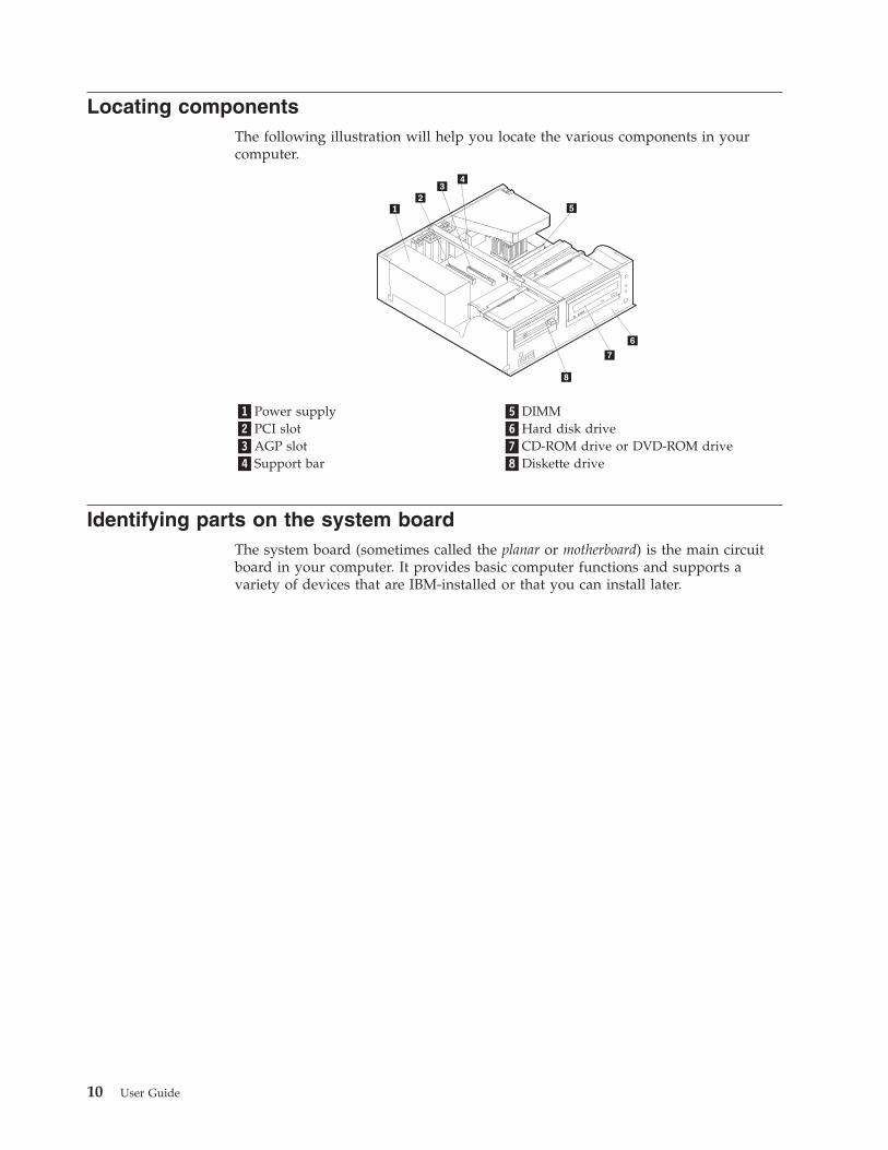
Locating componentsThe following illustration will help you locate the various components in yourcomputer.
�1�Power supply �5�DIMM�2�PCI slot �6�Hard disk drive�3�AGP slot �7�CD-ROM drive or DVD-ROM drive�4�Support bar �8�Diskette drive
Identifying parts on the system boardThe system board (sometimes called the planar or motherboard) is the main circuitboard in your computer. It provides basic computer functions and supports avariety of devices that are IBM-installed or that you can install later.
10 User Guide
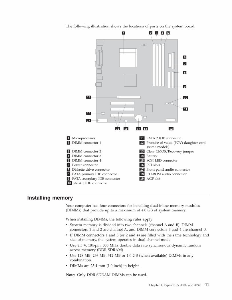
The following illustration shows the locations of parts on the system board.
�1� Microprocessor �11� SATA 2 IDE connector�2� DIMM connector 1 �12� Promise of value (POV) daughter card
(some models)�3� DIMM connector 2 �13� Clear CMOS/Recovery jumper�4� DIMM connector 3 �14� Battery�5� DIMM connector 4 �15� SCSI LED connector�6� Power connector �16� PCI slots�7� Diskette drive connector �17� Front panel audio connector�8� PATA primary IDE connector �18� CD-ROM audio connector�9� PATA secondary IDE connector �19� AGP slot�10�SATA 1 IDE connector
Installing memoryYour computer has four connectors for installing dual inline memory modules(DIMMs) that provide up to a maximum of 4.0 GB of system memory.
When installing DIMMs, the following rules apply:v System memory is divided into two channels (channel A and B). DIMM
connectors 1 and 2 are channel A, and DIMM connectors 3 and 4 are channel B.v If DIMM connectors 1 and 3 (or 2 and 4) are filled with the same technology and
size of memory, the system operates in dual channel mode.v Use 2.5 V, 184-pin, 333 MHz double data rate synchronous dynamic random
access memory (DDR SDRAM).v Use 128 MB, 256 MB, 512 MB or 1.0 GB (when available) DIMMs in any
combination.v DIMMs are 25.4 mm (1.0 inch) in height.
Note: Only DDR SDRAM DIMMs can be used.
Chapter 1. Types 8185, 8186, and 8192 11
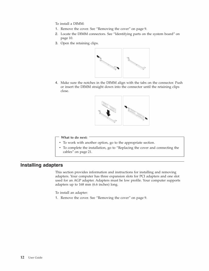
To install a DIMM:1. Remove the cover. See “Removing the cover” on page 9.2. Locate the DIMM connectors. See “Identifying parts on the system board” on
page 10.3. Open the retaining clips.
4. Make sure the notches in the DIMM align with the tabs on the connector. Pushor insert the DIMM straight down into the connector until the retaining clipsclose.
What to do next:
v To work with another option, go to the appropriate section.v To complete the installation, go to “Replacing the cover and connecting the
cables” on page 21.
Installing adaptersThis section provides information and instructions for installing and removingadapters. Your computer has three expansion slots for PCI adapters and one slotused for an AGP adapter. Adapters must be low profile. Your computer supportsadapters up to 168 mm (6.6 inches) long.
To install an adapter:1. Remove the cover. See “Removing the cover” on page 9.
12 User Guide

2. Pivot one of the drive bay latch handles toward the front of the computer andthen pivot the drive bay cage upward, as shown, until it is latched in the upposition. Repeat this procedure for the remaining drive bay.
3. Remove the support bar by pulling it outward from the computer.
4. Remove the adapter-slot-cover latch and the slot cover for the appropriateexpansion slot.
5. Remove the adapter from its static-protective package.6. Install the adapter into the appropriate slot on the system board.
Chapter 1. Types 8185, 8186, and 8192 13

7. Install the adapter-slot-cover latch.
8. Clear any cables that might impede the replacement of the drive bays.9. Replace the support bar and pivot the two drive bays back to their original
positions.
What to do next:
v To work with another option, go to the appropriate section.v To complete the installation, go to “Replacing the cover and connecting the
cables” on page 21.
Installing internal drivesThis section provides information and instructions for installing and removinginternal drives.
Internal drives are devices that your computer uses to read and store data. You canadd or replace drives to your computer to increase storage capacity and to enableyour computer to read other types of media such as CD-ROM.
Internal drives are installed in bays. In this book, the bays are referred to as bay 1,bay 2, and so on.
When you install an internal drive, it is important to note what type and size ofdrive that you can install in each bay. Also, it is important to correctly connect theinternal drive cables to the installed drive.
Drive specificationsYour computer might come with the following IBM-installed drives:v A 3.5-inch diskette drive in bay 1v A CD-ROM drive or DVD-ROM drive in bay 2 (some models)v A 3.5-inch hard disk drive in bay 3
Any bay that does not have a drive installed has a static shield and bay panelinstalled.
14 User Guide

The following illustration shows the locations of the drive bays.
The following list describes some of the drives that you can install in each bay andtheir height requirements:
�1�Bay 1 - Maximum height: 25.8 mm (1.0 in.) 3.5-inch diskette drive (preinstalled)�2�Bay 2 - Maximum height: 43.0 mm (1.7 in.) CD-ROM drive or DVD-ROM drive
(preinstalled in some models)�3�Bay 3 - Maximum height: 25.8 mm (1.0 in.) 3.5-inch hard disk drive (preinstalled)
Notes:
1. Drives that are greater than 43.0 mm (1.7 in.) high cannot be installed.2. Install removable media (tape or CD) drives in the accessible bay (bay 2).
Installing a CD-ROM or DVD-ROM driveTo install a CD-ROM drive or DVD-ROM drive in bay 2, follow these steps:1. Remove the cover (see “Removing the cover” on page 9).2. Remove the bay panel from the front bezel.3. Remove the metal shield from the drive bay by inserting a flat-blade
screwdriver into one of the slots and gently prying it loose.4. Make sure the drive is set correctly as the master device. Refer to the
documentation that comes with your CD-ROM drive or DVD-ROM drive formaster/slave jumper information.
5. Pivot the drive bay latch handle toward the front of the computer and thenpivot the drive bay cage upward, as shown, until it is latched in the upposition.
Chapter 1. Types 8185, 8186, and 8192 15

6. Install the drive into the bay. Align the screw holes and insert the two screws.
7. Each integrated drive electronics (IDE) drive requires two cables; a four-wirepower cable that connects to the power supply, and a signal cable that connectsto the system board. For a CD-ROM drive, you might also have an audio cable.To connect a CD-ROM drive or DVD-ROM drive to your computer, followthese steps:a. Locate the signal cable that comes with your computer or with the new
drive.b. Locate the PATA secondary IDE connector on the system board. See
“Identifying parts on the system board” on page 10.c. Connect one end of the signal cable to the PATA secondary IDE connector
on the system board and the other to the CD-ROM drive or DVD-ROMdrive.
d. Your computer has extra power connectors for connecting additional drives.Connect the power cable to the drive.
8. Clear any cables that might impede replacement of the drive cage.9. Pivot the drive cage back into place.
What to do next:
v To work with another option, go to the appropriate section.v To complete the installation, go to “Replacing the cover and connecting the
cables” on page 21.
16 User Guide

Installing security featuresTo help prevent hardware theft and unauthorized access to your computer, severalsecurity lock options are available. The following sections will help you identifyand install the various types of locks that might be available for your computer. Inaddition to physical locks, unauthorized use of your computer can be prevented bya software lock that locks the keyboard until a correct password is typed in.
Make sure that any security cables you install do not interfere with other computercables.
Identifying security locksThe following illustration shows the locations of the security features on the rear ofthe computer.
�1�Rope clip�2�Integrated cable lock
Rope clipUsing a 3/16-inch or 5-mm rope clip (sometimes referred to as a U-bolt), a steelsecurity cable, and a padlock can secure your computer to a desk, table, or othernon-permanent fixture. For computers designed to accommodate the rope clip,knockouts at the rear of the chassis are provided.
To install a rope clip:1. Remove the cover (see “Removing the cover” on page 9).2. Use a tool, such as a screwdriver, to remove the two metal knockouts.3. Press both sides of the air baffle and lift it outward from the computer to
remove.4. Insert the rope clip through the rear panel; then attach and tighten the nuts
with an appropriately sized or adjustable wrench.
Chapter 1. Types 8185, 8186, and 8192 17
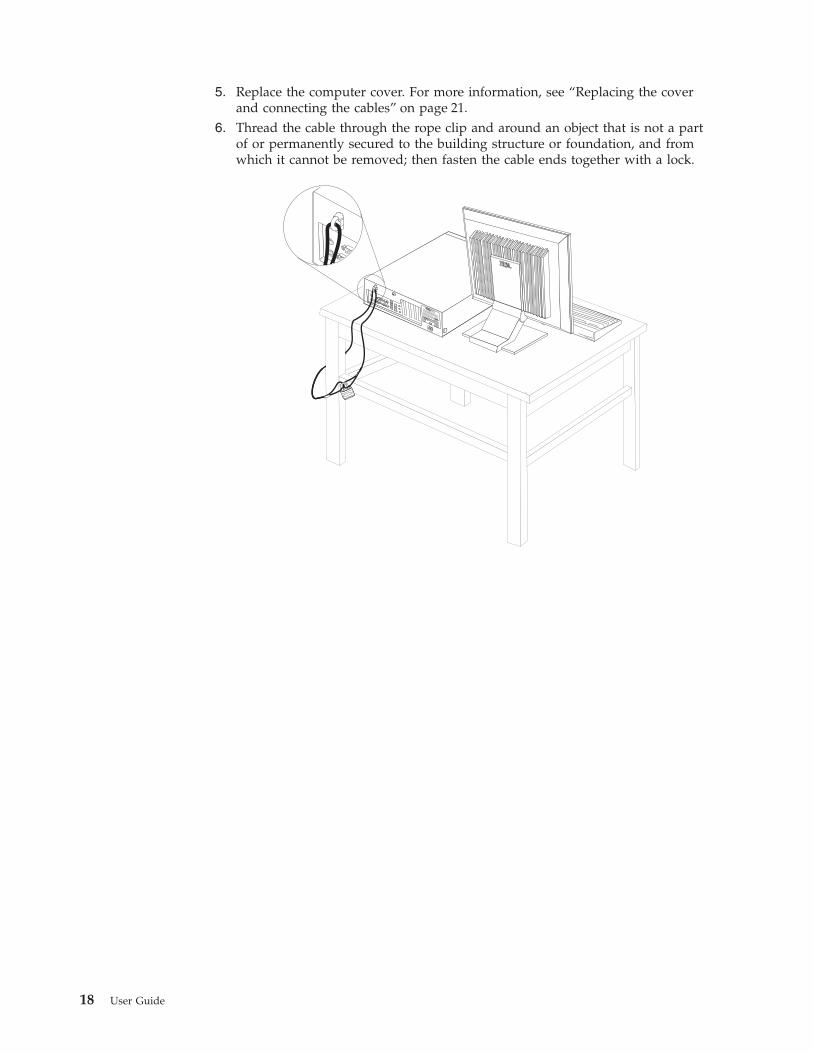
5. Replace the computer cover. For more information, see “Replacing the coverand connecting the cables” on page 21.
6. Thread the cable through the rope clip and around an object that is not a partof or permanently secured to the building structure or foundation, and fromwhich it cannot be removed; then fasten the cable ends together with a lock.
®®
18 User Guide

Integrated cable lockWith an integrated cable lock (sometimes referred to as a Kensington lock), youcan secure your computer to a desk, table, or other non-permanent fixture. Thecable lock attaches to a security slot at the rear of your computer and is operatedwith a key. This is the same type of lock used with many laptop computers. Youcan order a cable lock directly from IBM. Go to http://www.pc.ibm.com/supportand search on Kensington.
®®
Password protectionTo deter unauthorized use of your computer, you can use the IBM Setup Utilityprogram to set a password. When you turn on your computer you are prompted totype the password to unlock the keyboard for normal use.
What to do next:
v To work with another option, go to the appropriate section.v To complete the installation, go to “Replacing the cover and connecting the
cables” on page 21.
Changing the batteryYour computer has a special type of memory that maintains the date, time, andsettings for built-in features, such as parallel-port assignments (configuration). Abattery keeps this information active when you turn off the computer.
The battery normally requires no charging or maintenance throughout its life;however, no battery lasts forever. If the battery fails, the date, time, andconfiguration information (including passwords) are lost. An error message isdisplayed when you turn on the computer.
Chapter 1. Types 8185, 8186, and 8192 19
Refer to “Lithium battery notice” on page vi for information about replacing anddisposing of the battery.
To change the battery:1. Turn off the computer and all attached devices.2. Remove the cover. See “Removing the cover” on page 9.3. Locate the battery. See “Identifying parts on the system board” on page 10.4. If necessary, remove any adapters that impede access to the battery. See
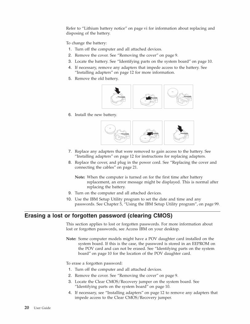
“Installing adapters” on page 12 for more information.5. Remove the old battery.
6. Install the new battery.
7. Replace any adapters that were removed to gain access to the battery. See“Installing adapters” on page 12 for instructions for replacing adapters.
8. Replace the cover, and plug in the power cord. See “Replacing the cover andconnecting the cables” on page 21.
Note: When the computer is turned on for the first time after batteryreplacement, an error message might be displayed. This is normal afterreplacing the battery.
9. Turn on the computer and all attached devices.10. Use the IBM Setup Utility program to set the date and time and any
passwords. See Chapter 5, “Using the IBM Setup Utility program”, on page 99.
Erasing a lost or forgotten password (clearing CMOS)This section applies to lost or forgotten passwords. For more information aboutlost or forgotten passwords, see Access IBM on your desktop.
Note: Some computer models might have a POV daughter card installed on thesystem board. If this is the case, the password is stored in an EEPROM onthe POV card and can not be erased. See “Identifying parts on the systemboard” on page 10 for the location of the POV daughter card.
To erase a forgotten password:1. Turn off the computer and all attached devices.2. Remove the cover. See “Removing the cover” on page 9.3. Locate the Clear CMOS/Recovery jumper on the system board. See
“Identifying parts on the system board” on page 10.4. If necessary, see “Installing adapters” on page 12 to remove any adapters that
impede access to the Clear CMOS/Recovery jumper.
20 User Guide
5. Move the jumper from the standard position (pins 1 and 2) to themaintenance or configure position (pins 2 and 3).
6. Replace the cover and connect the power cord. See “Replacing the cover andconnecting the cables”.
7. Restart the computer, leave it on for approximately 10 seconds. Turn off thecomputer by holding the power switch for approximately 5 seconds. Thecomputer will turn off.
8. Repeat steps 2 through 4 on page 20.9. Move the jumper back to the standard (pins 1 and 2).
10. Replace the cover and connect the power cord. See “Replacing the cover andconnecting the cables”.
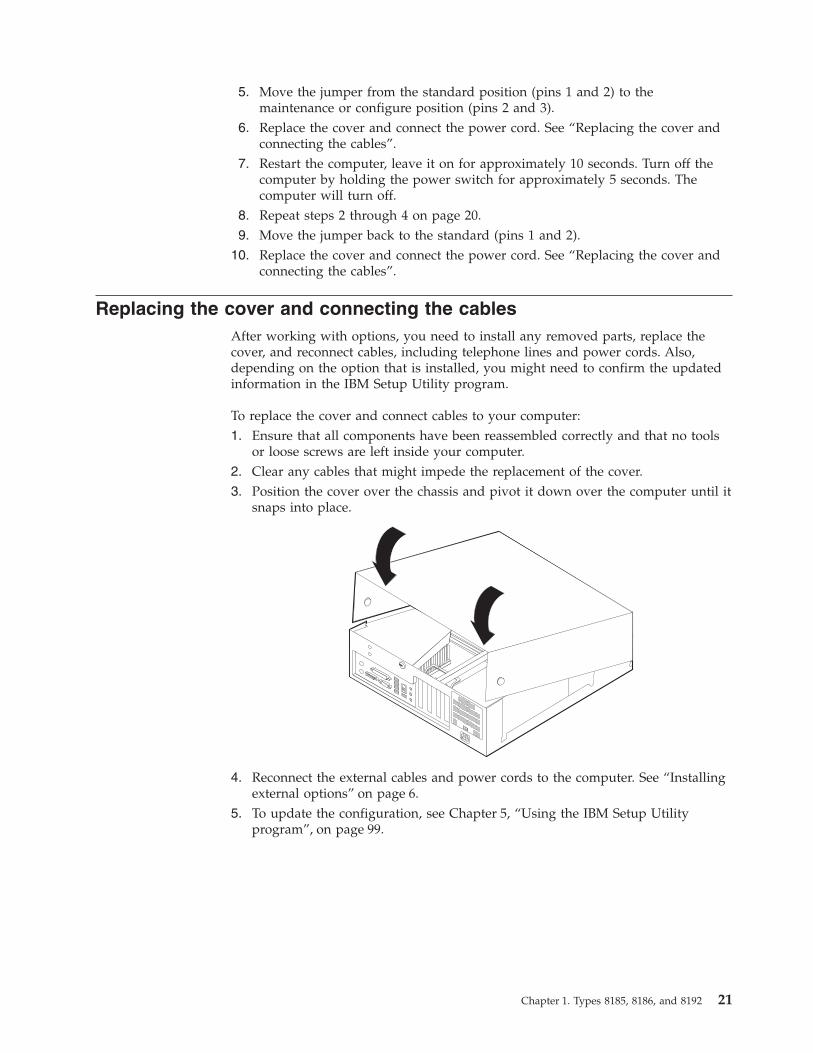
Replacing the cover and connecting the cablesAfter working with options, you need to install any removed parts, replace thecover, and reconnect cables, including telephone lines and power cords. Also,depending on the option that is installed, you might need to confirm the updatedinformation in the IBM Setup Utility program.
To replace the cover and connect cables to your computer:1. Ensure that all components have been reassembled correctly and that no tools
or loose screws are left inside your computer.2. Clear any cables that might impede the replacement of the cover.3. Position the cover over the chassis and pivot it down over the computer until it
snaps into place.
4. Reconnect the external cables and power cords to the computer. See “Installingexternal options” on page 6.
5. To update the configuration, see Chapter 5, “Using the IBM Setup Utilityprogram”, on page 99.
Chapter 1. Types 8185, 8186, and 8192 21

22 User Guide

Chapter 2. Types 8187, 8188, and 8193
This chapter provides an introduction to the features and options that are availablefor your computer. You can expand the capabilities of your computer by addingmemory, adapters, or drives. When installing an option, use these instructionsalong with the instructions that come with the option.
ImportantBefore you install or remove any option, read “Safety Information” on page v.These precautions and guidelines will help you work safely.
FeaturesThis section provides an overview of the computer features and preinstalledsoftware.
System informationThe following information covers a variety of models. For a listing of thefeatures for your specific model, click Information in the Access IBMPredesktop Area. See “Access IBM Predesktop Area” on page ix.
Microprocessor (varies by model type)v Intel® Pentium® 4 processor with 512 KB of internal L2 cache memory and Intel
NetBurst™ micro-architecturev Intel Celeron® processor with 128 KB of internal L2 cache memory
Memory
v Support for four dual inline memory modules (DIMMs)v 512 KB flash memory for system programs
Internal drives
v 3.5-inch, 1.44 MB diskette drivev Internal hard disk drivev EIDE CD drive or DVD drive (some models)
© Copyright IBM Corp. 2003 23
Video subsystem
v An integrated graphics controller for a Video Graphics Array (VGA) monitorv Accelerated graphics port (AGP) video adapter slot on the system board
Audio subsystem
v AC’97 with ADI 1981B Audio Codecv Line in, line out, and microphone connectors on the rear panel
Connectivity
v 10/100 Mbps integrated Intel Ethernet controller that supports the Wake onLAN® feature (some models)
v 10/100/1000 Mbps integrated Intel Ethernet controller that supports the Wakeon LAN feature (some models)
v Soft modem V.90/V.44 (some models)
System management features
v Remote Program Load (RPL) and Dynamic Host Configuration Protocol (DHCP)v Wake on LANv Wake on Ring (in the IBM Setup Utility program, this feature is called Serial Port
Ring Detect for an external modem)v Remote Administrationv Automatic power-on startupv System Management (SM) BIOS and SM softwarev Ability to store POST hardware test results
Input/output features
v 25-pin, Extended Capabilities Port (ECP)/Extended Parallel Port (EPP)v 9-pin serial connectorv Eight 4-pin, USB connectors (two on front panel and six on rear panel)v PS/2® mouse connectorv PS/2 keyboard connectorv Ethernet connectorv VGA monitor connectorv Three audio connectors (line in, line out, and microphone)
Expansion
v Four drive baysv Three 32-bit peripheral component interconnect (PCI) adapter slotsv One accelerated graphics port (AGP) expansion slot
Power
v 230 W power supply with manual voltage selection switchv Automatic 50/60 Hz input frequency switchingv Advanced Power Management supportv Advanced Configuration and Power Interface (ACPI) support
Security features
v User and administrator passwords
24 User Guide
v Support for the addition of a rope clip and lockable cablev Support for the addition of an integrated cable lockv Startup sequence controlv Startup without diskette drive, keyboard, or mousev Unattended start modev Diskette and hard disk I/O controlv Serial and parallel port I/O controlv Security profile by device
IBM preinstalled softwareYour computer might come with preinstalled software. If it does, an operatingsystem, device drivers to support built-in features, and other support programs areincluded.
Operating systems (preinstalled) (varies by model type)
Note: Not all countries or regions will have these operating systems.v Microsoft® Windows XP Homev Microsoft Windows XP Professionalv Microsoft Windows 2000
Operating systems (tested for compatibility)2
v Microsoft Windows NT® Workstation Version 4.0v Microsoft Windows 98 Second Edition
2. The operating systems listed here are being tested for compatibility at the time this publication goes to press. Additionaloperating systems might be identified by IBM as compatible with your computer following the publication of this booklet.Corrections and additions to this list are subject to change. To determine if an operating system has been tested for compatibility,check the Web site of the operating system vendor.
Chapter 2. Types 8187, 8188, and 8193 25

SpecificationsThis section lists the physical specifications for your computer.
Dimensions
Height: 140 mm (5.5 in.)
Width: 425 mm (16.7 in.)
Depth: 425 mm (16.7 in)
Weight
Minimum configuration as shipped: 10.0 kg (22 lb)
Maximum configuration: 11.4 kg (25.0 lb)
Environment
Air temperature:
System on: 10° to 35°C (50° to 95° F)System off: 10° to 43°C (50° to 110° F)
Maximum altitude: 2134 m (7000 ft)Note: The maximum altitude, 2134 m (7000 ft), isthe maximum altitude at which the specified airtemperatures apply. At higher altitudes, themaximum air temperatures are lower than thosespecified.
Humidity:
System on: 8% to 80%
System off: 8% to 80%
Electrical input
Input voltage:
Low range:
Minimum: 90 V ac
Maximum: 180 V ac
Input frequency range: 47–53 Hz
Voltage switch setting: 115 V ac
High range:
Minimum: 137 V ac
Maximum: 265 V ac
Input frequency range: 57–63 Hz
Voltage switch setting: 230 V ac
Input kilovolt-amperes (kVA) (approximate):
Minimum configuration as shipped: 0.08 kVA
Maximum configuration: 0.3 kVA
Note: Power consumption and heat output varydepending on the number and type of optionalfeatures installed and the power-managementoptional features in use.
Heat output (approximate) in British thermal units (Btu)per hour:
Minimum configuration: 257 Btu/hr (75 watts)
Maximum configuration: 785 Btu/hr (230 watts)
Airflow
Approximately 0.51 cubic meters per minute (18 cubicfeet per minute) maximum
Acoustical noise-emission values
Average sound-pressure levels:
At operator position:
Idle: 30 dBA
Operating: 32 dBA
At bystander position - 1 meter (3.3 ft):
Idle: 26 dBA
Operating: 30 dBA
Declared (upper limit) sound-power levels:
Idle: 4.0 bels
Operating: 4.3 bels
Note: These levels were measured in controlledacoustical environments according to the proceduresspecified by the American National StandardsInstitute (ANSI) S12.10 and ISO 7779 and are reportedin accordance with ISO 9296. Actual sound-pressurelevels in a given location might exceed the averagevalues stated because of room reflections and othernearby noise sources. The declared sound-powerlevels indicate an upper limit, below which a largenumber of computers will operate.
26 User Guide
Available optionsThe following are some available options:v External options
– Parallel port devices, such as printers and external drives– Serial port devices, such as external modems and digital cameras– Audio devices, such as external speakers for the sound system– USB devices, such as printers, joysticks, and scanners– Security device, such as a rope clip– Monitors
v Internal options– System memory, called dual inline memory modules (DIMMs)– Peripheral component interconnect (PCI) adapters– Accelerated graphics port (AGP) adapters– Internal drives, such as:
- CD drive or DVD drive (some models)- Hard disk drive- Diskette drives and other removable media drives
For the latest information about available options, see the following World WideWeb pages:v http://www.ibm.com/pc/us/options/v http://www.ibm.com/pc/support/
You can also obtain information by calling the following telephone numbers:v Within the United States, call 1-800-IBM-2YOU (1-800-426-2968), your IBM
reseller, or IBM marketing representative.v Within Canada, call 1-800-565-3344 or 1-800-IBM-4YOU.v Outside the United States and Canada, contact your IBM reseller or IBM
marketing representative.
Tools requiredTo install some options in your computer, you might need a flat-blade or Phillipsscrewdriver. Additional tools might be needed for certain options. See theinstructions that come with the option.
Handling static-sensitive devicesStatic electricity, although harmless to you, can seriously damage computercomponents and options.
When you add an option, do not open the static-protective package containing theoption until you are instructed to do so.
When you handle options and other computer components, take these precautionsto avoid static electricity damage:v Limit your movement. Movement can cause static electricity to build up around
you.v Always handle components carefully. Handle adapters and memory modules by
the edges. Never touch any exposed circuitry.
Chapter 2. Types 8187, 8188, and 8193 27

v Prevent others from touching components.v When you install a new option, touch the static-protective package containing
the option to a metal expansion-slot cover or other unpainted metal surface onthe computer for at least two seconds. This reduces static electricity in thepackage and your body.
v When possible, remove the option and install it directly in the computer withoutsetting the option down. When this is not possible, place the static-protectivepackage that the option came in on a smooth, level surface and place the optionon it.
v Do not place the option on the computer cover or other metal surface.
Installing external optionsThis section shows the various external connectors on your computer to which youcan attach external options, such as external speakers, a printer, or a scanner. Forsome external options, you must install additional software in addition to makingthe physical connection. When adding an external option, use the information inthis section to identify the required connector, and then use the instructions thatcome with the option to help you make the connection and install any software ordevice drivers that are required for the option.
Locating the connectors on the front of your computerThe following illustration shows the locations of the connectors on the front of thecomputer.
�1�USB connector�2�USB connector
28 User Guide
Locating the connectors on the rear of your computerThe following illustration shows the locations of the connectors on the rear of thecomputer.
�1�Power connector �8� AGP slot�2�Mouse connector �9� Audio line out connector�3�Parallel connector �10�Microphone connector�4�USB connectors �11�USB connectors�5�Ethernet connector �12�VGA monitor connector�6�Audio line in connector �13�Serial connector�7�PCI slots �14�Keyboard connector
Note: Some connectors on the rear of the computer are color-coded to help you todetermine where to connect the cables on your computer.
Chapter 2. Types 8187, 8188, and 8193 29

Connector Description
Mouse connector Used to attach a mouse, trackball, or other pointing device thatuses a standard mouse connector.
Parallel connector Used to attach a parallel printer, parallel scanner, or otherdevices that use a 25-pin parallel connector.
USB connectors Used to attach a device that requires a Universal Serial Bus(USB) connection, such as a USB scanner or USB printer. If youhave more than eight USB devices, you can purchase a USBhub, which you can use to connect additional USB devices.
Ethernet connector Used to attach an Ethernet cable for a local area network(LAN).Note: To operate the computer within FCC Class B limits, usea Category 5 Ethernet cable.
Audio line in connector Used to receive audio signals from an external audio device,such as a stereo system. When you attach an external audiodevice, a cable is connected between the audio line outconnector of the device and the audio line in connector of thecomputer.
Audio line out connector Used to send audio signals from the computer to externaldevices, such as powered stereo speakers (speakers withbuilt-in amplifiers), headphones, multimedia keyboards, or theaudio line in connector on a stereo system or other externalrecording device.
Microphone connector Used to attach a microphone to your computer when you wantto record voice or other sounds on the hard disk if you usespeech-recognition software.
Serial connector Used to attach an external modem, serial printer, or otherdevices that use a 9-pin serial connector.
Keyboard connector Used to attach a keyboard that uses a standard keyboardconnector.
Obtaining device driversYou can obtain device drivers for operating systems that are not preinstalled athttp://www.ibm.com/pc/support/ on the World Wide Web. Installationinstructions are provided in README files with the device-driver files.
30 User Guide

Removing the cover
Important:Read “Safety Information” on page v and “Handling static-sensitive devices”on page 27 before removing the cover.
To remove the cover:1. Shut down your operating system, remove any media (diskettes, CDs, or tapes)
from the drives, and turn off all attached devices and the computer.2. Unplug all power cords from electrical outlets.3. Disconnect all cables attached to the computer. This includes power cords,
input/output (I/O) cables, and any other cables that are connected to thecomputer.
4. Press the buttons on the sides of the computer and pivot the rear end of thecover up toward the front of the computer.
Chapter 2. Types 8187, 8188, and 8193 31

Locating componentsThe following illustration will help you locate the various components in yourcomputer.
�1�CD drive or DVD drive �7� DIMMs�2�USB connector �8� Microprocessor and heat sink�3�USB connector �9� AGP slot�4�Optional drive bay �10�Battery�5�Hard disk drive �11�PCI slots�6�Diskette drive
Identifying parts on the system boardThe system board (sometimes called the planar or motherboard) is the main circuitboard in your computer. It provides basic computer functions and supports avariety of devices that are IBM-installed or that you can install later.
32 User Guide

The following illustration shows the locations of parts on the system board.
�1� Microprocessor �11� SATA 2 IDE connector�2� DIMM connector 1 �12� Promise of value (POV) daughter card
(some models)�3� DIMM connector 2 �13� Clear CMOS/Recovery jumper�4� DIMM connector 3 �14� Battery�5� DIMM connector 4 �15� SCSI LED connector�6� Power connector �16� PCI slots�7� Diskette drive connector �17� Front panel audio connector�8� PATA primary IDE connector �18� CD-ROM audio connector�9� PATA secondary IDE connector �19� AGP slot�10�SATA 1 IDE connector
Installing memoryYour computer has four connectors for installing dual inline memory modules(DIMMs) that provide up to a maximum of 4.0 GB of system memory.
When installing DIMMs, the following rules apply:v System memory is divided into two channels (channel A and B). DIMM
connectors 1 and 2 are channel A, and DIMM connectors 3 and 4 are channel B.v If DIMM connectors 1 and 3 (or 2 and 4) are filled with the same technology and
size of memory, the system operates in dual channel mode.v Use 2.5 V, 184-pin, 333 MHz double data rate synchronous dynamic random
access memory (DDR SDRAM).v Use 128 MB, 256 MB, 512 MB or 1.0 GB (when available) DIMMs in any
combination.v DIMMs are 25.4 mm (1.0 inch) in height.
Note: Only DDR SDRAM DIMMs can be used.
Chapter 2. Types 8187, 8188, and 8193 33

To install a DIMM:1. Remove the cover. See “Removing the cover” on page 31.2. You might have to remove an adapter to gain access to the DIMM slots. See
“Installing adapters” on page 34.3. Locate the DIMM connectors. See “Identifying parts on the system board” on
page 32.4. Open the retaining clips.
5. Make sure the notches in the DIMM align with the tabs on the connector. Pushor insert the DIMM straight down into the connector until the retaining clipsclose.
What to do next:
v To work with another option, go to the appropriate section.v To complete the installation, go to “Replacing the cover and connecting the
cables” on page 45.
Installing adaptersThis section provides information and instructions for installing and removingadapters. Your computer has three expansion slots for PCI adapters and one slotused for an AGP adapter. You can install an adapter up to 340 mm (13.4 inches)long.
To install an adapter:1. Remove the cover. See “Removing the cover” on page 31.
34 User Guide

2. Remove the adapter-slot-cover latch and the slot cover for the appropriateexpansion slot.
3. Remove the adapter from its static-protective package.4. Install the adapter into the appropriate slot on the system board.5. Install the adapter-slot-cover latch.
What to do next:
v To work with another option, go to the appropriate section.v To complete the installation, go to “Replacing the cover and connecting the
cables” on page 45.
Chapter 2. Types 8187, 8188, and 8193 35
Installing internal drivesThis section provides information and instructions for installing and removinginternal drives.
Internal drives are devices that your computer uses to read and store data. You canadd drives to your computer to increase storage capacity and to enable yourcomputer to read other types of media. Some of the different drives that areavailable for your computer are:v Parallel Advanced Technology Attachment (PATA) hard disk drivesv Serial ATA hard disk drivesv CD drives or DVD drivesv Tape drivesv Removable media drives
Note: These different drives are also referred to as integrated drive electronics(IDE) drives.
Internal drives are installed in bays. In this book, the bays are referred to as bay 1,bay 2, and so on.
When you install an internal drive, it is important to note what type and size ofdrive that you can install in each bay. Also, it is important to correctly connect theinternal drive cables to the installed drive.
Drive specificationsYour computer comes with the following IBM-installed drives:v A CD drive or DVD drive in bay 1 (some models)v A 3.5-inch hard disk drive in bay 3v A 3.5-inch diskette drive in bay 4
Any bay that does not have a drive installed has a static shield and bay panelinstalled.
36 User Guide
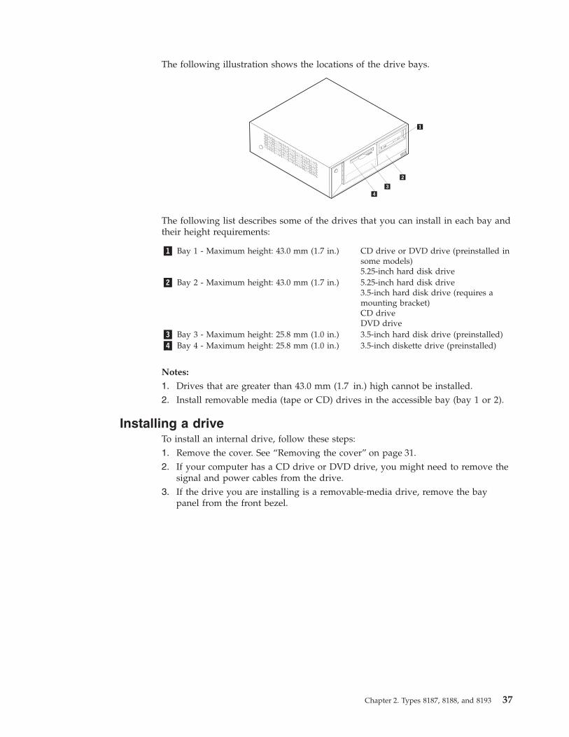
The following illustration shows the locations of the drive bays.
The following list describes some of the drives that you can install in each bay andtheir height requirements:
�1� Bay 1 - Maximum height: 43.0 mm (1.7 in.) CD drive or DVD drive (preinstalled insome models)5.25-inch hard disk drive
�2� Bay 2 - Maximum height: 43.0 mm (1.7 in.) 5.25-inch hard disk drive3.5-inch hard disk drive (requires amounting bracket)CD driveDVD drive
�3� Bay 3 - Maximum height: 25.8 mm (1.0 in.) 3.5-inch hard disk drive (preinstalled)�4� Bay 4 - Maximum height: 25.8 mm (1.0 in.) 3.5-inch diskette drive (preinstalled)
Notes:
1. Drives that are greater than 43.0 mm (1.7 in.) high cannot be installed.2. Install removable media (tape or CD) drives in the accessible bay (bay 1 or 2).
Installing a driveTo install an internal drive, follow these steps:1. Remove the cover. See “Removing the cover” on page 31.2. If your computer has a CD drive or DVD drive, you might need to remove the
signal and power cables from the drive.3. If the drive you are installing is a removable-media drive, remove the bay
panel from the front bezel.
Chapter 2. Types 8187, 8188, and 8193 37
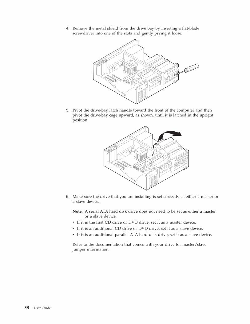
4. Remove the metal shield from the drive bay by inserting a flat-bladescrewdriver into one of the slots and gently prying it loose.
5. Pivot the drive-bay latch handle toward the front of the computer and thenpivot the drive-bay cage upward, as shown, until it is latched in the uprightposition.
6. Make sure the drive that you are installing is set correctly as either a master ora slave device.
Note: A serial ATA hard disk drive does not need to be set as either a masteror a slave device.
v If it is the first CD drive or DVD drive, set it as a master device.v If it is an additional CD drive or DVD drive, set it as a slave device.v If it is an additional parallel ATA hard disk drive, set it as a slave device.
Refer to the documentation that comes with your drive for master/slavejumper information.
38 User Guide

7. Install the drive into the bay. Align the screw holes and insert the two screws.
8. Pivot the drive-bay cage back into place.9. A hard disk drive requires two cables; a power cable that connects to the power
supply and a signal cable that connects to the system board.v A parallel ATA hard disk drive requires a four-wire power cable.
v A serial ATA hard disk drive requires a five-wire power cable.
The steps to connect a drive are different depending on the type of drive you areconnecting. Use one of the following procedure for your drive connection.
Connecting the first CD drive or DVD drive1. Locate the three-connector signal cable that comes with your computer or with
the new drive.2. Locate the PATA secondary IDE connector on the system board. See
“Identifying parts on the system board” on page 32.3. Connect one end of the signal cable to the drive and the other to the PATA
secondary IDE connector on the system board. To reduce electronic noise, usethe connectors at the end of the cable only.
Chapter 2. Types 8187, 8188, and 8193 39
4. Your computer has extra power connectors for additional drives. Connect apower connector to the drive.
5. If you have a CD-ROM audio cable, connect it to the drive and to the systemboard. See “Identifying parts on the system board” on page 32.
Connecting an additional CD drive, DVD drive, or parallel ATAhard disk drive1. Locate the PATA secondary IDE connector on the system board and the
three-connector signal cable. See “Identifying parts on the system board” onpage 32.
2. Connect the extra connector in the signal cable to the new drive.3. Your computer has extra power connectors for additional drives. Connect a
power connector to the drive.
Connecting a serial ATA hard disk driveA serial hard disk drive can be connected to either the SATA 1 IDE or SATA 2 IDEconnector.1. Locate the signal cable that comes with the new drive.2. Locate an available SATA IDE connector on the system board. See “Identifying
parts on the system board” on page 32.3. Connect one end of the signal cable to the drive and the other to an available
SATA IDE connector on the system board.4. Your computer has extra power connectors for additional drives. Connect a
power connector to the drive.
What to do nextv To work with another option, go to the appropriate section.v To complete the installation, go to “Replacing the cover and connecting the
cables” on page 45.
Installing security featuresTo help prevent hardware theft and unauthorized access to your computer, severalsecurity lock options are available. The following sections will help you identifyand install the various types of locks that might be available for your computer. Inaddition to physical locks, unauthorized use of your computer can be prevented bya software lock that locks the keyboard until a correct password is typed in.
Make sure that any security cables you install do not interfere with other computercables.
40 User Guide
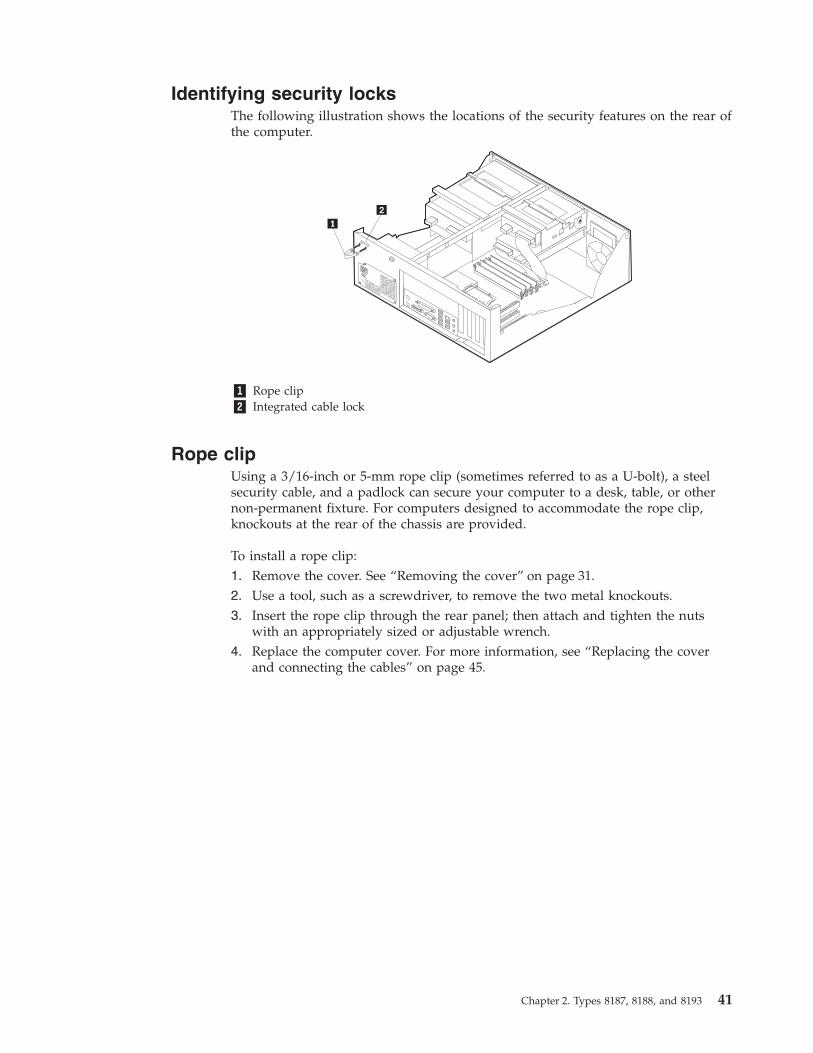
Identifying security locksThe following illustration shows the locations of the security features on the rear ofthe computer.
�1� Rope clip�2� Integrated cable lock
Rope clipUsing a 3/16-inch or 5-mm rope clip (sometimes referred to as a U-bolt), a steelsecurity cable, and a padlock can secure your computer to a desk, table, or othernon-permanent fixture. For computers designed to accommodate the rope clip,knockouts at the rear of the chassis are provided.
To install a rope clip:1. Remove the cover. See “Removing the cover” on page 31.2. Use a tool, such as a screwdriver, to remove the two metal knockouts.3. Insert the rope clip through the rear panel; then attach and tighten the nuts
with an appropriately sized or adjustable wrench.4. Replace the computer cover. For more information, see “Replacing the cover
and connecting the cables” on page 45.
Chapter 2. Types 8187, 8188, and 8193 41

5. Thread the cable through the rope clip and around an object that is not a partof or permanently secured to the building structure or foundation, and fromwhich it cannot be removed; then fasten the cable ends together with a lock.
®
42 User Guide
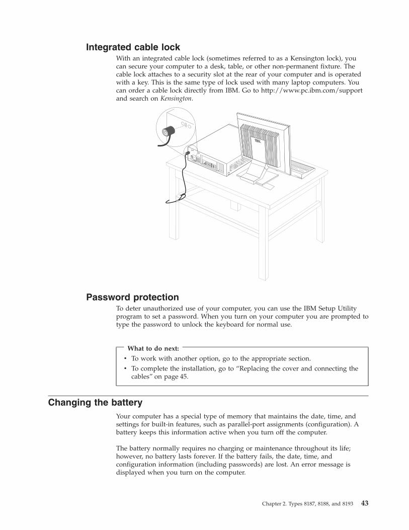
Integrated cable lockWith an integrated cable lock (sometimes referred to as a Kensington lock), youcan secure your computer to a desk, table, or other non-permanent fixture. Thecable lock attaches to a security slot at the rear of your computer and is operatedwith a key. This is the same type of lock used with many laptop computers. Youcan order a cable lock directly from IBM. Go to http://www.pc.ibm.com/supportand search on Kensington.
®
Password protectionTo deter unauthorized use of your computer, you can use the IBM Setup Utilityprogram to set a password. When you turn on your computer you are prompted totype the password to unlock the keyboard for normal use.
What to do next:
v To work with another option, go to the appropriate section.v To complete the installation, go to “Replacing the cover and connecting the
cables” on page 45.
Changing the batteryYour computer has a special type of memory that maintains the date, time, andsettings for built-in features, such as parallel-port assignments (configuration). Abattery keeps this information active when you turn off the computer.
The battery normally requires no charging or maintenance throughout its life;however, no battery lasts forever. If the battery fails, the date, time, andconfiguration information (including passwords) are lost. An error message isdisplayed when you turn on the computer.
Chapter 2. Types 8187, 8188, and 8193 43
Refer to “Lithium battery notice” on page vi for information about replacing anddisposing of the battery.
To change the battery:1. Turn off the computer and all attached devices.2. Remove the cover. See “Removing the cover” on page 31.3. Locate the battery. See “Identifying parts on the system board” on page 32.4. If necessary, remove any adapters that impede access to the battery. See
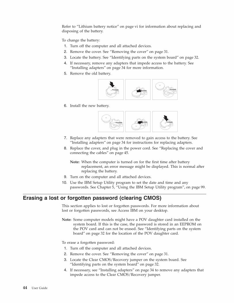
“Installing adapters” on page 34 for more information.5. Remove the old battery.
6. Install the new battery.
7. Replace any adapters that were removed to gain access to the battery. See“Installing adapters” on page 34 for instructions for replacing adapters.
8. Replace the cover, and plug in the power cord. See “Replacing the cover andconnecting the cables” on page 45.
Note: When the computer is turned on for the first time after batteryreplacement, an error message might be displayed. This is normal afterreplacing the battery.
9. Turn on the computer and all attached devices.10. Use the IBM Setup Utility program to set the date and time and any
passwords. See Chapter 5, “Using the IBM Setup Utility program”, on page 99.
Erasing a lost or forgotten password (clearing CMOS)This section applies to lost or forgotten passwords. For more information aboutlost or forgotten passwords, see Access IBM on your desktop.
Note: Some computer models might have a POV daughter card installed on thesystem board. If this is the case, the password is stored in an EEPROM onthe POV card and can not be erased. See “Identifying parts on the systemboard” on page 32 for the location of the POV daughter card.
To erase a forgotten password:1. Turn off the computer and all attached devices.2. Remove the cover. See “Removing the cover” on page 31.3. Locate the Clear CMOS/Recovery jumper on the system board. See
“Identifying parts on the system board” on page 32.4. If necessary, see “Installing adapters” on page 34 to remove any adapters that
impede access to the Clear CMOS/Recovery jumper.
44 User Guide

5. Move the jumper from the standard position (pins 1 and 2) to themaintenance or configure position (pins 2 and 3).
6. Replace the cover and connect the power cord. See “Replacing the cover andconnecting the cables”.
7. Restart the computer, leave it on for approximately 10 seconds. Turn off thecomputer by holding the power switch for approximately 5 seconds. Thecomputer will turn off.
8. Repeat steps 2 through 4 on page 44.9. Move the jumper back to the standard (pins 1 and 2).
10. Replace the cover and connect the power cord. See “Replacing the cover andconnecting the cables”.
Replacing the cover and connecting the cablesAfter working with options, you need to install any removed parts, replace thecover, and reconnect any cables, including telephone lines and power cords. Also,depending on the option that is installed, you might need to confirm the updatedinformation in the IBM Setup Utility program.
To replace the cover and connect cables to your computer:1. Ensure that all components have been reassembled correctly and that no tools
or loose screws are left inside your computer.2. Clear any cables that might impede the replacement of the cover.3. Position the cover over the chassis and pivot it down over the computer until it
snaps into place.
4. Reconnect the external cables and power cords to the computer. See “Installingexternal options” on page 28.
5. To update the configuration, see Chapter 5, “Using the IBM Setup Utilityprogram”, on page 99.
Chapter 2. Types 8187, 8188, and 8193 45

46 User Guide

Chapter 3. Types 8196 and 8197
This chapter provides an introduction to the features and options that are availablefor your computer. You can expand the capabilities of your computer by addingmemory, adapters, or drives. When installing an option, use these instructionsalong with the instructions that come with the option.
ImportantBefore you install or remove any option, read “Safety Information” on page v.These precautions and guidelines will help you work safely.
FeaturesThis section provides an overview of the computer features and preinstalledsoftware.
System informationThe following information covers a variety of models. For a listing of thefeatures for your specific model, click Information in the Access IBMPredesktop Area. See “Access IBM Predesktop Area” on page ix.
Microprocessor (varies by model type)v Intel® Pentium® 4 processor with 512 KB of internal L2 cache memory and Intel
NetBurst™ micro-architecturev Intel Celeron® processor with 128 KB of internal L2 cache memory
Memory
v Support for four dual inline memory modules (DIMMs)v 512 KB flash memory for system programs
© Copyright IBM Corp. 2003 47

Internal drives
v 3.5-inch, 1.44 MB diskette drivev Internal hard disk drivev EIDE CD drive or DVD drive (some models)
Video subsystem
v An integrated graphics controller for a Video Graphics Array (VGA) monitorv Accelerated graphics port (AGP) video adapter slot on the system board
Audio subsystem
v AC’97 with ADI 1981B Audio Codecv Line in, line out, and microphone connectors on the rear panel
Connectivity
v 10/100 Mbps integrated Intel Ethernet controller that supports the Wake onLAN® feature (some models)
v 10/100/1000 Mbps integrated Intel Ethernet controller that supports the Wakeon LAN feature (some models)
v Soft modem V.90/V.44 (some models)
System management features
v Remote Program Load (RPL) and Dynamic Host Configuration Protocol (DHCP)v Wake on LANv Wake on Ring (in the IBM Setup Utility program, this feature is called Serial Port
Ring Detect for an external modem)v Remote Administrationv Automatic power-on startupv System Management (SM) BIOS and SM softwarev Ability to store POST hardware test results
Input/output features
v 25-pin, Extended Capabilities Port (ECP)/Extended Parallel Port (EPP)v 9-pin serial connectorv Eight 4-pin, USB connectors (two on front panel and six on rear panel)v PS/2® mouse connectorv PS/2 keyboard connectorv Ethernet connectorv VGA monitor connectorv Three audio connectors (line in, line out, and microphone)
Expansion
v Four drive baysv Three 32-bit peripheral component interconnect (PCI) adapter slotsv One accelerated graphics port (AGP) expansion slot (some models)
Power
v 230 W power supply with manual voltage selection switchv Automatic 50/60 Hz input frequency switching
48 User Guide

v Advanced Power Management supportv Advanced Configuration and Power Interface (ACPI) support
Security features
v User and administrator passwordsv Support for the addition of a rope clip and lockable cablev Support for the addition of an integrated cable lockv Support for a padlock on the chassisv Startup sequence controlv Startup without diskette drive, keyboard, or mousev Unattended start modev Diskette and hard disk I/O controlv Serial and parallel port I/O controlv Security profile by device
IBM preinstalled softwareYour computer might come with preinstalled software. If it does, an operatingsystem, device drivers to support built-in features, and other support programs areincluded.
Operating systems preinstalled (varies by model type)
Note: Not all countries or regions will have these operating systems.v Microsoft® Windows XP Professionalv Microsoft Windows XP Homev Microsoft Windows 2000
Operating systems (tested for compatibility)3
v Microsoft Windows NT® Workstation Version 4.0v Microsoft Windows 98 Second Edition
3. The operating systems listed here are being tested for compatibility at the time this publication goes to press. Additionaloperating systems might be identified by IBM as compatible with your computer following the publication of this booklet.Corrections and additions to this list are subject to change. To determine if an operating system has been tested for compatibility,check the Web site of the operating system vendor.
Chapter 3. Types 8196 and 8197 49

SpecificationsThis section lists the physical specifications for your computer.
Dimensions
Height: 398 mm (15.67 in.)
Width: 180 mm (7.08 in.)
Depth: 402 mm (15.82 in.)
Weight
Minimum configuration as shipped: 7.6 kg (16.8 lb)
Maximum configuration: 9.97 kg (22 lb)
Environment
Air temperature:
System on: 10° to 35°C (50° to 95° F)System off: 10° to 43°C (50° to 110° F)
Maximum altitude: 2134 m (7000 ft)Note: The maximum altitude, 2134 m (7000 ft), isthe maximum altitude at which the specified airtemperatures apply. At higher altitudes, themaximum air temperatures are lower than thosespecified.
Humidity:
System on: 8% to 80%
System off: 8% to 80%
Electrical input
Input voltage:
Low range:
Minimum: 90 V ac
Maximum: 180 V ac
Input frequency range: 47–53 Hz
Voltage switch setting: 115 V ac
High range:
Minimum: 137 V ac
Maximum: 265 V ac
Input frequency range: 57–63 Hz
Voltage switch setting: 230 V ac
Input kilovolt-amperes (kVA) (approximate):
Minimum configuration as shipped: 0.08 kVA
Maximum configuration: 0.30 kVA
Note: Power consumption and heat output varydepending on the number and type of optionalfeatures installed and the power-managementoptional features in use.
Heat output (approximate) in British thermal units (Btu)per hour:
Minimum configuration: 257 Btu/hr (75 watts)
Maximum configuration: 785 Btu/hr (230 watts)
Airflow
Approximately 0.68 cubic meters every minute (24cubic feet every minute) maximum
Acoustical noise-emission values
For microprocessors less than 2.8 GHz:
Average sound-pressure levels:
At operator position:
Idle: 28 dBA
Operating: 35 dBA
At bystander position - 1 meter (3.3 ft):
Idle: 25 dBA
Operating: 33 dBA
Declared (upper limit) sound-power levels:
Idle: 4.0 bels
Operating: 4.7 bels
For microprocessors greater than or equal to 2.8 GHz:
Average sound-pressure levels:
At operator position:
Idle: 33 dBA
Operating: 35 dBA
At bystander position - 1 meter (3.3 ft):
Idle: 30 dBA
Operating: 33 dBA
Declared (upper limit) sound-power levels:
Idle: 4.4 bels
Operating: 4.7 bels
Note: These levels were measured in controlledacoustical environments according to the proceduresspecified by the American National Standards Institute(ANSI) S12.10 and ISO 7779 and are reported inaccordance with ISO 9296. Actual sound-pressure levelsin a given location might exceed the average valuesstated because of room reflections and other nearby noisesources. The declared sound-power levels indicate anupper limit, below which a large number of computerswill operate.
50 User Guide
Available optionsThe following are some available options:v External options
– Parallel port devices, such as printers and external drives– Serial port devices, such as external modems and digital cameras– Audio devices, such as external speakers for the sound system– USB devices, such as printers, joysticks, and scanners– Security device, such as a rope clip– Monitors
v Internal options– System memory, called dual inline memory modules (DIMMs)– Peripheral component interconnect (PCI) adapters– Accelerated graphics port (AGP) adapters– Internal drives, such as:
- CD drive or DVD drive- Hard disk- Diskette drives and other removable media drives
For the latest information about available options, see the following World WideWeb pages:v http://www.ibm.com/pc/us/options/v http://www.ibm.com/pc/support/
You can also obtain information by calling the following telephone numbers:v Within the United States, call 1-800-IBM-2YOU (1-800-426-2968), your IBM
reseller, or IBM marketing representative.v Within Canada, call 1-800-565-3344 or 1-800-IBM-4YOU.v Outside the United States and Canada, contact your IBM reseller or IBM
marketing representative.
Tools requiredTo install some options in your computer, you might need a flat-blade or Phillipsscrewdriver. Additional tools might be needed for certain options. See theinstructions that come with the option.
Handling static-sensitive devicesStatic electricity, although harmless to you, can seriously damage computercomponents and options.
When you add an option, do not open the static-protective package containing theoption until you are instructed to do so.
When you handle options and other computer components, take these precautionsto avoid static electricity damage:v Limit your movement. Movement can cause static electricity to build up around
you.v Always handle components carefully. Handle adapters and memory modules by
the edges. Never touch any exposed circuitry.
Chapter 3. Types 8196 and 8197 51
v Prevent others from touching components.v When you install a new option, touch the static-protective package containing
the option to a metal expansion-slot cover or other unpainted metal surface onthe computer for at least two seconds. This reduces static electricity in thepackage and your body.
v When possible, remove the option and install it directly in the computer withoutsetting the option down. When this is not possible, place the static-protectivepackage that the option came in on a smooth, level surface and place the optionon it.
v Do not place the option on the computer cover or other metal surface.
Installing external optionsThis section shows the various external connectors on your computer to which youcan attach external options, such as external speakers, a printer, or a scanner. Forsome external options, you must install additional software in addition to makingthe physical connection. When adding an external option, use the information inthis section to identify the required connector, and then use the instructions thatcome with the option to help you make the connection and install any software ordevice drivers that are required for the option.
52 User Guide
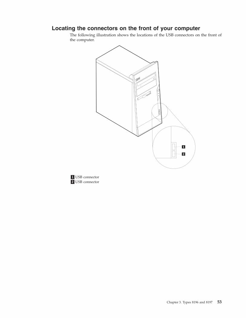
Locating the connectors on the front of your computerThe following illustration shows the locations of the USB connectors on the front ofthe computer.
�1�USB connector�2�USB connector
Chapter 3. Types 8196 and 8197 53

Locating the connectors on the rear of your computerThe following illustration shows the locations of the connectors on the back of thecomputer.
�1�Power connector �8� USB connectors�2�Mouse connector �9� Ethernet connector�3�Keyboard connector �10�Microphone connector�4�Serial connector �11�Audio line out connector�5�Parallel connector �12�Audio line in connector�6�VGA monitor connector �13�AGP slot�7�USB connectors �14�PCI slots
Note: Some connectors on the rear of the computer are color-coded to help you todetermine where to connect the cables on your computer.
54 User Guide

Connector Description
Mouse connector Used to attach a mouse, trackball, or other pointing device thatuses a standard mouse connector.
Keyboard connector Used to attach a keyboard that uses a standard keyboardconnector.
Serial connector Used to attach an external modem, serial printer, or otherdevices that use a 9-pin serial connector.
Parallel connector Used to attach a parallel printer, parallel scanner, or otherdevices that use a 25-pin parallel connector.
USB connectors Used to attach a device that requires a Universal Serial Bus(USB) connection, such as a USB scanner or USB printer. If youhave more than eight USB devices, you can purchase a USBhub, which you can use to connect additional USB devices.
Ethernet connector Used to attach an Ethernet cable for a local area network(LAN).Note: To operate the computer within FCC Class B limits, usea Category 5 Ethernet cable.
Microphone connector Used to attach a microphone to your computer when you wantto record voice or other sounds on the hard disk if you usespeech-recognition software.
Audio line out connector Used to send audio signals from the computer to externaldevices, such as powered stereo speakers (speakers withbuilt-in amplifiers), headphones, multimedia keyboards, or theaudio line in connector on a stereo system or other externalrecording device.
Audio line in connector Used to receive audio signals from an external audio device,such as a stereo system. When you attach an external audiodevice, a cable is connected between the audio line outconnector of the device and the audio line in connector of thecomputer.
Obtaining device driversYou can obtain device drivers for operating systems that are not preinstalled athttp://www.ibm.com/pc/support/ on the World Wide Web. Installationinstructions are provided in README files with the device-driver files.
Chapter 3. Types 8196 and 8197 55

Removing the cover
ImportantRead “Safety Information” on page v and “Handling static-sensitive devices”on page 51 before removing the cover.
To remove the cover:1. Shut down your operating system, remove any media (diskettes, CDs, or tapes)
from the drives, and turn off all attached devices and the computer.2. Unplug all power cords from electrical outlets.3. Disconnect all cables attached to the computer. This includes power cords,
input/output (I/O) cables, and any other cables that are connected to thecomputer.
4. Remove the two screws at the rear of the left side cover and slide the cover tothe rear to remove.
56 User Guide
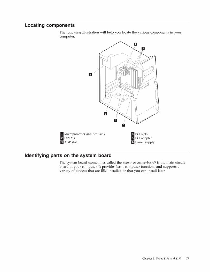
Locating componentsThe following illustration will help you locate the various components in yourcomputer.
�1�Microprocessor and heat sink �4�PCI slots�2�DIMMs �5�PCI adapter�3�AGP slot �6�Power supply
Identifying parts on the system boardThe system board (sometimes called the planar or motherboard) is the main circuitboard in your computer. It provides basic computer functions and supports avariety of devices that are IBM-installed or that you can install later.
Chapter 3. Types 8196 and 8197 57

The following illustration shows the locations of parts on the system board.
�1� Microprocessor �11� SATA 2 IDE connector�2� DIMM connector 1 �12� Promise of value (POV) daughter card
(some models)�3� DIMM connector 2 �13� Clear CMOS/Recovery jumper�4� DIMM connector 3 �14� Battery�5� DIMM connector 4 �15� SCSI LED connector�6� Power connector �16� PCI slots�7� Diskette drive connector �17� Front panel audio connector�8� PATA primary IDE connector �18� CD-ROM audio connector�9� PATA secondary IDE connector �19� AGP slot�10�SATA 1 IDE connector
Installing memoryYour computer has four connectors for installing dual inline memory modules(DIMMs) that provide up to a maximum of 4.0 GB of system memory.
When installing DIMMs, the following rules apply:v System memory is divided into two channels (channel A and B). DIMM
connectors 1 and 2 are channel A, and DIMM connectors 3 and 4 are channel B.v If DIMM connectors 1 and 3 (or 2 and 4) are filled with the same technology and
size of memory, the system operates in dual channel mode.v Use 2.5 V, 184-pin, 333 MHz double data rate synchronous dynamic random
access memory (DDR SDRAM).v Use 128 MB, 256 MB, 512 MB, or 1.0 GB (when available) DIMMs in any
combination.v DIMMs are 25.4 mm (1.0 inch) in height.
Note: Only DDR SDRAM DIMMs can be used.
58 User Guide

To install a DIMM:1. Remove the cover. See “Removing the cover” on page 56.2. You might have to remove an adapter to gain access to the DIMM slots. See
“Installing adapters” on page 60.3. Locate the DIMM connectors. See “Identifying parts on the system board” on
page 57.4. Open the retaining clips.
5. Make sure the notches in the DIMM align with the tabs on the connector. Pushor insert the DIMM straight down into the connector until the retaining clipsclose.
What to do next:
v Replace any adapters that were removed.v To work with another option, go to the appropriate section.v To complete the installation, go to “Replacing the cover and connecting the
cables” on page 70.
Chapter 3. Types 8196 and 8197 59

Installing adaptersThis section provides information and instructions for installing and removingadapters. Your computer has three expansion slots for PCI adapters. You can installan adapter up to 228 mm (9 inches) long.
To install an adapter:1. Remove the cover. See “Removing the cover” on page 56.2. Remove the adapter slot cover for the appropriate expansion slot.
3. Remove the adapter from its static-protective package.4. Install the adapter into the appropriate slot on the system board.
60 User Guide

5. Secure the adapter with the screw as shown.
What to do next
v To work with another option, go to the appropriate section.v To complete the installation, go to “Replacing the cover and connecting the
cables” on page 70.
Installing internal drivesThis section provides information and instructions for installing and removinginternal drives.
Internal drives are devices that your computer uses to read and store data. You canadd drives to your computer to increase storage capacity and to enable yourcomputer to read other types of media. Some of the different drives that areavailable for your computer are:v Parallel Advanced Technology Attachment (PATA) hard disk drivesv Serial ATA hard disk drivesv CD drives or DVD drivesv Removable media drives
Note: These different drives are also referred to as integrated drive electronics(IDE) drives.
Internal drives are installed in bays. In this book, the bays are referred to as bay 1,bay 2, and so on.
When you install an internal drive, it is important to note what type and size ofdrive that you can install in each bay. Also, it is important to correctly connect theinternal drive cables to the installed drive.
Chapter 3. Types 8196 and 8197 61

Drive specificationsYour computer comes with the following IBM-installed drives:v A CD drive or DVD drive in bay 1v A 3.5-inch diskette disk drive in bay 3v A 3.5-inch hard drive in bay 4
Any bay that does not have a drive installed has a static shield and bay panelinstalled.
The following illustration shows the locations of the drive bays.
The following table describes some of the drives you can install in each bay andtheir height requirements.
�1�Bay 1 - Maximum height: 43.0 mm (1.7 in.) CD drive or DVD drive (preinstalled insome models)5.25-inch hard disk drive
�2�Bay 2 - Maximum height: 43.0 mm (1.7 in.) 5.25-inch hard disk drive3.5-inch hard disk drive (requires amounting bracket)CD driveDVD drive
�3�Bay 3 - Maximum height: 25.8 mm (1.0 in.) 3.5-inch diskette drive (preinstalled)�4�Bay 4 - Maximum height: 25.8 mm (1.0 in.) 3.5-inch hard disk drive
Notes:
1. Drives that are greater than 43.0 mm (1.7 in.) high cannot be installed.2. Install removable media (tape or CD) drives in the accessible bays (bay 1 or 2).
Installing a driveTo install an internal drive, follow these steps:1. Remove the cover. See “Removing the cover” on page 56.2. If your computer has a CD drive or DVD drive, you might need to remove the
signal and power cables from the drive.
62 User Guide

3. Remove the bay panel from the drive bay by inserting a flat-blade screwdriverat the end and gently prying it loose.
4. Remove the metal shield from the drive bay by inserting a flat-bladescrewdriver into one of the slots and gently prying it loose.
5. Make sure the drive that you are installing is set correctly as either a master ora slave device.
Note: A serial ATA hard disk drive does not need to be set as either a masteror a slave device.
v If it is the first CD drive or DVD drive, set it as a master device.v If it is an additional CD drive or DVD drive, set it as a slave device.v If it is an additional parallel ATA hard disk drive, set it as a slave device.
Refer to the documentation that comes with your drive for master/slavejumper information.
Chapter 3. Types 8196 and 8197 63

6. Install the drive into the bay. Align the screw holes and install two screws tosecure the drive.
7. A hard disk drive requires two cables; a power cable that connects to the powersupply and a signal cable that connects to the system board.v A parallel ATA hard disk drive requires a four-wire power cable.
v A serial ATA hard disk drive requires a five-wire power cable.
The steps to connect a drive are different depending on the type of drive you areconnecting. Use one of the following procedures for your drive connection.
Connecting the first CD drive or DVD drive1. Locate the three-connector signal cable that comes with your computer or with
the new drive.2. Locate the PATA secondary IDE connector on the system board. See
“Identifying parts on the system board” on page 57.
64 User Guide

3. Connect one end of the signal cable to the drive and the other to the PATAsecondary IDE connector on the system board. To reduce electronic noise, usethe connectors at the end of the cable only.
4. Your computer has extra power connectors for additional drives. Connect apower connector to the drive.
5. If you have a CD-ROM audio cable, connect it to the drive and to the systemboard. See “Identifying parts on the system board” on page 57.
Connecting an additional CD drive, DVD drive, or parallel ATAhard disk driveAn additional drive can be connected to either the PATA primary IDE or PATAsecondary IDE connector.1. Locate an available PATA IDE connector on the three-connector signal cable
attached to either the PATA primary IDE or PATA secondary IDE connector onthe system board. See “Identifying parts on the system board” on page 57.
2. Connect the extra connector in the signal cable to the new drive.3. Your computer has extra power connectors for additional drives. Connect a
power connector to the drive.
Connecting a serial ATA hard disk driveA serial hard disk drive can be connected to either the SATA 1 IDE or SATA 2 IDEconnector.1. Locate the signal cable that comes with the new drive.2. Locate an available SATA IDE connector on the system board. See “Identifying
parts on the system board” on page 57.3. Connect one end of the signal cable to the drive and the other to an available
SATA IDE connector on the system board.4. Your computer has extra power connectors for additional drives. Connect a
power connector to the drive.
What to do next
v To work with another option, go to the appropriate section.v To complete the installation, go to “Replacing the cover and connecting the
cables” on page 70.
Installing security featuresTo help prevent hardware theft and unauthorized access to your computer, severalsecurity lock options are available. The following sections will help you identifyand install the various types of locks that might be available for your computer. Inaddition to physical locks, unauthorized use of your computer can be prevented bya software lock that locks the keyboard until a correct password is typed in.
Make sure that any security cables you install do not interfere with other computercables.
Chapter 3. Types 8196 and 8197 65
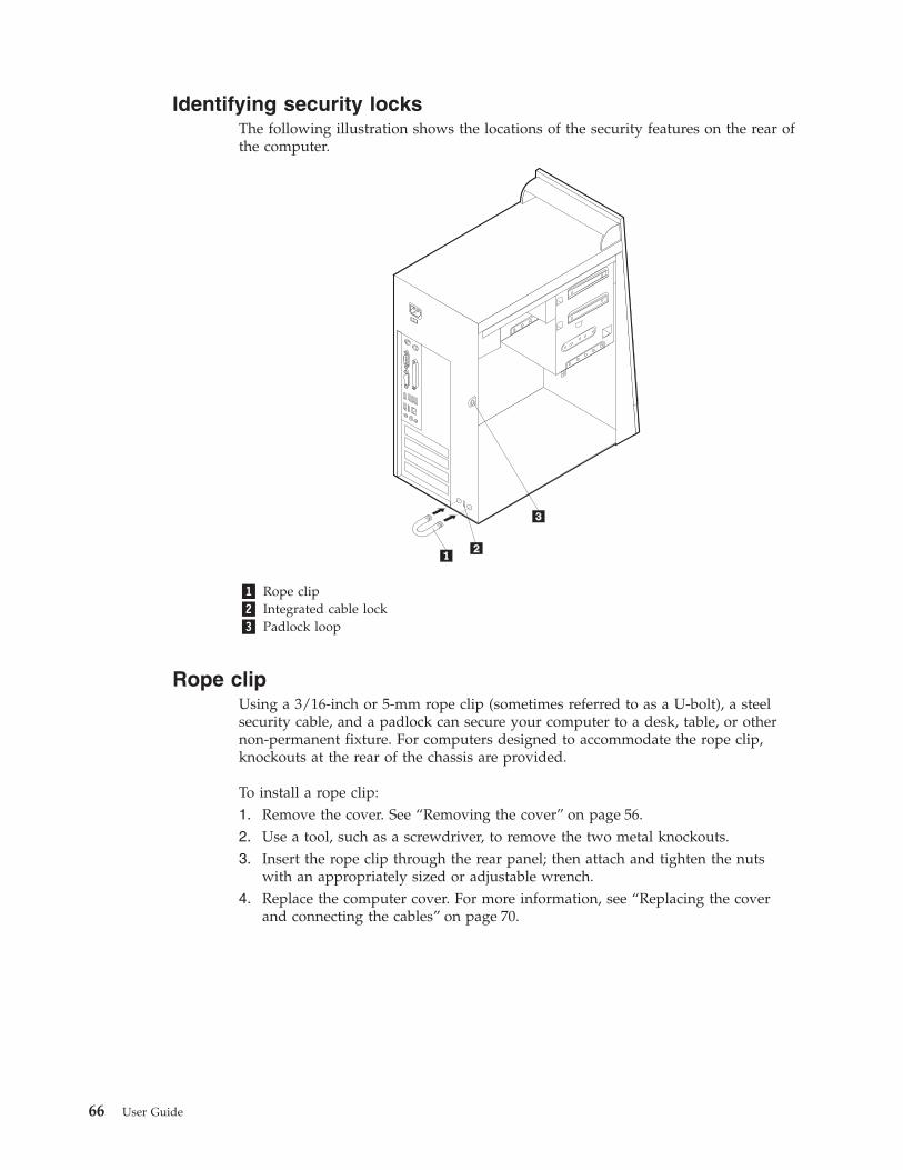
Identifying security locksThe following illustration shows the locations of the security features on the rear ofthe computer.
�1� Rope clip�2� Integrated cable lock�3� Padlock loop
Rope clipUsing a 3/16-inch or 5-mm rope clip (sometimes referred to as a U-bolt), a steelsecurity cable, and a padlock can secure your computer to a desk, table, or othernon-permanent fixture. For computers designed to accommodate the rope clip,knockouts at the rear of the chassis are provided.
To install a rope clip:1. Remove the cover. See “Removing the cover” on page 56.2. Use a tool, such as a screwdriver, to remove the two metal knockouts.3. Insert the rope clip through the rear panel; then attach and tighten the nuts
with an appropriately sized or adjustable wrench.4. Replace the computer cover. For more information, see “Replacing the cover
and connecting the cables” on page 70.
66 User Guide

5. Thread the cable through the rope clip and around an object that is not a partof or permanently secured to the building structure or foundation, and fromwhich it cannot be removed; then fasten the cable ends together with a lock.
®®
Chapter 3. Types 8196 and 8197 67

Integrated cable lockWith an integrated cable lock (sometimes referred to as a Kensington lock), youcan secure your computer to a desk, table, or other non-permanent fixture. Thecable lock attaches to a security slot at the rear of your computer and is operatedwith a key. This is the same type of lock used with many laptop computers. Youcan order a cable lock directly from IBM. Go to http://www.pc.ibm.com/supportand search on Kensington.
®®
Password protectionTo deter unauthorized use of your computer, you can use the IBM Setup Utilityprogram to set a password. When you turn on your computer you are prompted totype the password to unlock the keyboard for normal use.
What to do next
v To work with another option, go to the appropriate section.v To complete the installation, go to “Replacing the cover and connecting the
cables” on page 70.
Changing the batteryYour computer has a special type of memory that maintains the date, time, andsettings for built-in features, such as parallel-port assignments (configuration). Abattery keeps this information active when you turn off the computer.
The battery normally requires no charging or maintenance throughout its life;however, no battery lasts forever. If the battery fails, the date, time, andconfiguration information (including passwords) are lost. An error message isdisplayed when you turn on the computer.
68 User Guide

Refer to “Lithium battery notice” on page vi for information about replacing anddisposing of the battery.
To change the battery:1. Turn off the computer and all attached devices.2. Unplug the power cord and remove the cover. See “Removing the cover” on
page 56.3. Locate the battery. See “Identifying parts on the system board” on page 57.4. If necessary, remove any adapters that impede access to the battery. See
“Installing adapters” on page 60 for more information.5. Remove the old battery.
6. Install the new battery.
7. Replace any adapters that were removed to gain access to the battery. See“Installing adapters” on page 60 for instructions for replacing adapters.
8. Replace the cover, and plug in the power cord. See “Replacing the cover andconnecting the cables” on page 70.
Note: When the computer is turned on for the first time after batteryreplacement, an error message might be displayed. This is normal afterreplacing the battery.
9. Turn on the computer and all attached devices.10. Use the IBM Setup Utility program to set the date and time and any
passwords.
Erasing a lost or forgotten password (clearing CMOS)This section applies to lost or forgotten passwords. For more information aboutlost or forgotten passwords, go to Access IBM.
Note: Some computer models might have a POV daughter card installed on thesystem board. If this is the case, the password is stored in an EEPROM onthe POV card and can not be erased. See “Identifying parts on the systemboard” on page 57 for the location of the POV daughter card.
To erase a forgotten password:1. Turn off the computer and all attached devices.2. Remove the cover. See “Removing the cover” on page 56.3. Locate the Clear CMOS/Recovery jumper on the system board. See
“Identifying parts on the system board” on page 57.4. If necessary, see “Installing adapters” on page 60 to remove any adapters that
impede access to the Clear CMOS/Recovery jumper.
Chapter 3. Types 8196 and 8197 69
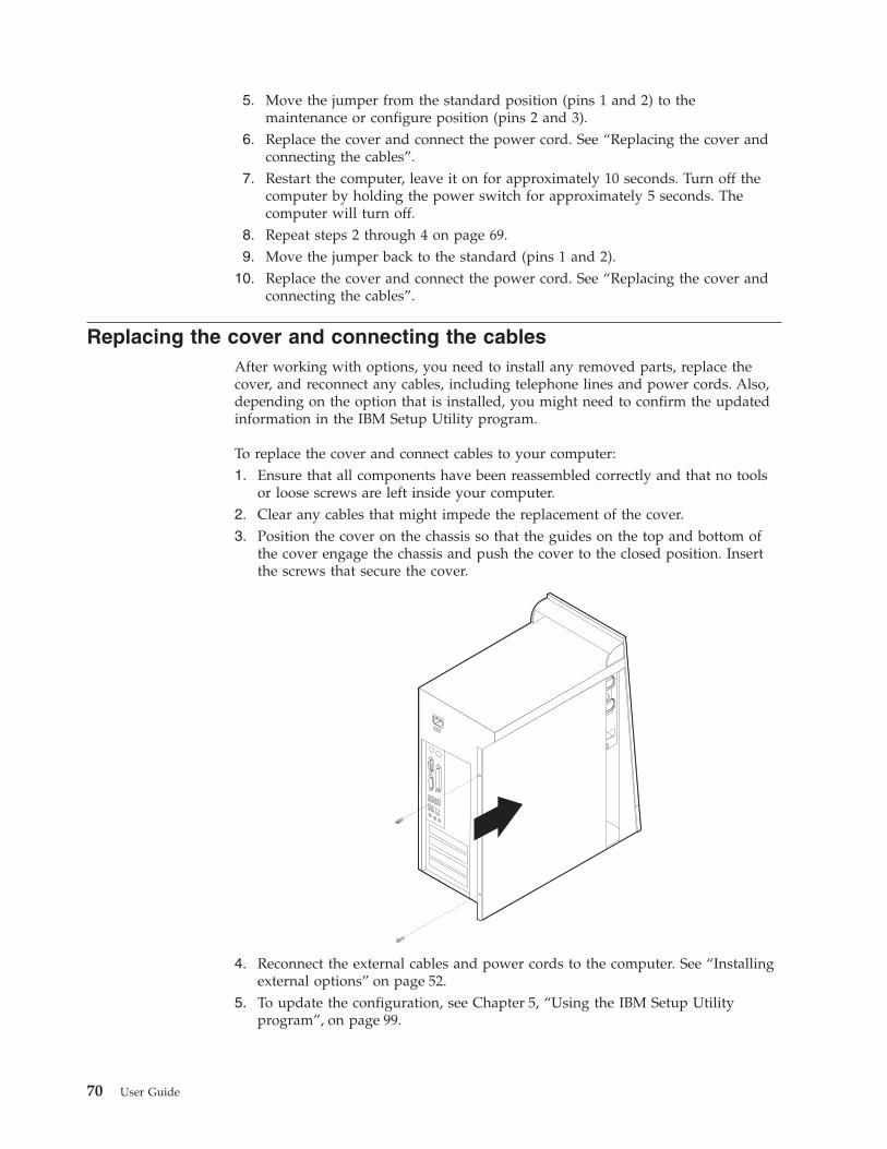
5. Move the jumper from the standard position (pins 1 and 2) to themaintenance or configure position (pins 2 and 3).
6. Replace the cover and connect the power cord. See “Replacing the cover andconnecting the cables”.
7. Restart the computer, leave it on for approximately 10 seconds. Turn off thecomputer by holding the power switch for approximately 5 seconds. Thecomputer will turn off.
8. Repeat steps 2 through 4 on page 69.9. Move the jumper back to the standard (pins 1 and 2).
10. Replace the cover and connect the power cord. See “Replacing the cover andconnecting the cables”.
Replacing the cover and connecting the cablesAfter working with options, you need to install any removed parts, replace thecover, and reconnect any cables, including telephone lines and power cords. Also,depending on the option that is installed, you might need to confirm the updatedinformation in the IBM Setup Utility program.
To replace the cover and connect cables to your computer:1. Ensure that all components have been reassembled correctly and that no tools
or loose screws are left inside your computer.2. Clear any cables that might impede the replacement of the cover.3. Position the cover on the chassis so that the guides on the top and bottom of
the cover engage the chassis and push the cover to the closed position. Insertthe screws that secure the cover.
4. Reconnect the external cables and power cords to the computer. See “Installingexternal options” on page 52.
5. To update the configuration, see Chapter 5, “Using the IBM Setup Utilityprogram”, on page 99.
70 User Guide

Important:When the power cord is first plugged in, the computer might appear to turnon for a few seconds and then turn off. This is a normal sequence to enablethe computer to initialize.
Chapter 3. Types 8196 and 8197 71

72 User Guide

Chapter 4. Types 8189, 8190, 8194, 8195, 8432, and 8433
This chapter provides an introduction to the features and options that are availablefor your computer. You can expand the capabilities of your computer by addingmemory, adapters, or drives. When installing an option, use these instructionsalong with the instructions that come with the option.
ImportantBefore you install or remove any option, read “Safety Information” on page v.These precautions and guidelines will help you work safely.
FeaturesThis section provides an overview of the computer features and preinstalledsoftware.
System informationThe following information covers a variety of models. For a listing of thefeatures for your specific model, click Information in the Access IBMPredesktop Area. See “Access IBM Predesktop Area” on page ix.
Microprocessor (varies by model type)v Intel® Pentium® 4 processor with 512 KB of internal L2 cache memory and Intel
NetBurst™ micro-architecturev Intel Celeron® processor with 128 KB of internal L2 cache memory
Memory
v Support for four dual inline memory modules (DIMMs)v 512 KB flash memory for system programs
© Copyright IBM Corp. 2003 73

Internal drives
v 3.5-inch, 1.44 MB diskette drivev Internal hard disk drivev EIDE CD drive or DVD drive
Video subsystem
v An integrated graphics controller for a Video Graphics Array (VGA) monitorv Accelerated graphics port (AGP) video adapter slot on the system board
Audio subsystem
v AC’97 with ADI 1981B Audio Codecv Line in, line out, and microphone connectors on the rear panel
Connectivity
v 10/100 Mbps integrated Intel Ethernet controller that supports the Wake onLAN® feature (some models)
v 10/100/1000 Mbps integrated Intel Ethernet controller that supports the Wakeon LAN feature (some models)
v Soft modem V.90/V.44 (some models)
System management features
v Remote Program Load (RPL) and Dynamic Host Configuration Protocol (DHCP)v Wake on LANv Wake on Ring (in the IBM Setup Utility program, this feature is called Serial Port
Ring Detect for an external modem)v Remote Administrationv Automatic power-on startupv System Management (SM) BIOS and SM softwarev Ability to store POST hardware test results
Input/output features
v 25-pin, Extended Capabilities Port (ECP)/Extended Parallel Port (EPP)v 9-pin serial connectorv Eight 4-pin, USB connectors (two on front panel and six on rear panel)v PS/2® mouse connectorv PS/2 keyboard connectorv Ethernet connectorv VGA monitor connectorv Three audio connectors (line in, line out, and microphone)v IEEE 1394 connector (some models)v Front connectors for microphone and headphone (some models)
Expansion
v Five drive baysv Three 32-bit peripheral component interconnect (PCI) adapter slotsv One accelerated graphics port (AGP) expansion slot
74 User Guide

Power
v 230 W power supply with manual voltage selection switchv Automatic 50/60 Hz input frequency switchingv Advanced Power Management supportv Advanced Configuration and Power Interface (ACPI) support
Security features
v User and administrator passwordsv Support for the addition of a rope clip and lockable cablev Support for the addition of an integrated cable lockv Startup sequence controlv Startup without diskette drive, keyboard, or mousev Unattended start modev Diskette and hard disk I/O controlv Serial and parallel port I/O controlv Security profile by device
IBM preinstalled softwareYour computer might come with preinstalled software. If it does, an operatingsystem, device drivers to support built-in features, and other support programs areincluded.
Operating systems (preinstalled) (varies by model type)
Note: Not all countries or regions will have these operating systems.v Microsoft® Windows XP Homev Microsoft Windows XP Professionalv Microsoft Windows 2000
Operating systems (tested for compatibility)4
v Microsoft Windows NT® Workstation Version 4.0v Microsoft Windows 98 Second Edition
4. The operating systems listed here are being tested for compatibility at the time this publication goes to press. Additionaloperating systems might be identified by IBM as compatible with your computer following the publication of this booklet.Corrections and additions to this list are subject to change. To determine if an operating system has been tested for compatibility,check the Web site of the operating system vendor.
Chapter 4. Types 8189, 8190, 8194, 8195, 8432, and 8433 75
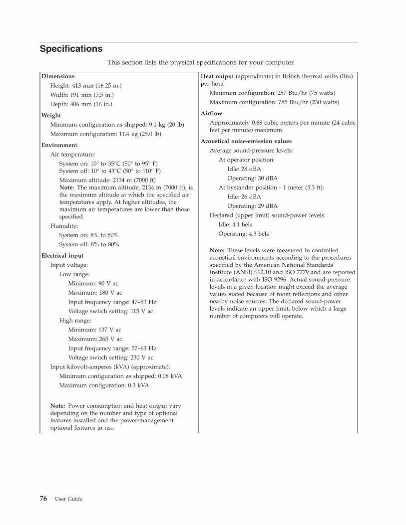
SpecificationsThis section lists the physical specifications for your computer.
Dimensions
Height: 413 mm (16.25 in.)
Width: 191 mm (7.5 in.)
Depth: 406 mm (16 in.)
Weight
Minimum configuration as shipped: 9.1 kg (20 lb)
Maximum configuration: 11.4 kg (25.0 lb)
Environment
Air temperature:
System on: 10° to 35°C (50° to 95° F)System off: 10° to 43°C (50° to 110° F)
Maximum altitude: 2134 m (7000 ft)Note: The maximum altitude, 2134 m (7000 ft), isthe maximum altitude at which the specified airtemperatures apply. At higher altitudes, themaximum air temperatures are lower than thosespecified.
Humidity:
System on: 8% to 80%
System off: 8% to 80%
Electrical input
Input voltage:
Low range:
Minimum: 90 V ac
Maximum: 180 V ac
Input frequency range: 47–53 Hz
Voltage switch setting: 115 V ac
High range:
Minimum: 137 V ac
Maximum: 265 V ac
Input frequency range: 57–63 Hz
Voltage switch setting: 230 V ac
Input kilovolt-amperes (kVA) (approximate):
Minimum configuration as shipped: 0.08 kVA
Maximum configuration: 0.3 kVA
Note: Power consumption and heat output varydepending on the number and type of optionalfeatures installed and the power-managementoptional features in use.
Heat output (approximate) in British thermal units (Btu)per hour:
Minimum configuration: 257 Btu/hr (75 watts)
Maximum configuration: 785 Btu/hr (230 watts)
Airflow
Approximately 0.68 cubic meters per minute (24 cubicfeet per minute) maximum
Acoustical noise-emission values
Average sound-pressure levels:
At operator position:
Idle: 28 dBA
Operating: 30 dBA
At bystander position - 1 meter (3.3 ft):
Idle: 26 dBA
Operating: 29 dBA
Declared (upper limit) sound-power levels:
Idle: 4.1 bels
Operating: 4.3 bels
Note: These levels were measured in controlledacoustical environments according to the proceduresspecified by the American National StandardsInstitute (ANSI) S12.10 and ISO 7779 and are reportedin accordance with ISO 9296. Actual sound-pressurelevels in a given location might exceed the averagevalues stated because of room reflections and othernearby noise sources. The declared sound-powerlevels indicate an upper limit, below which a largenumber of computers will operate.
76 User Guide

Available optionsThe following are some available options:v External options
– Parallel port devices, such as printers and external drives– Serial port devices, such as external modems and digital cameras– Audio devices, such as external speakers for the sound system– USB devices, such as printers, joysticks, and scanners– Security device, such as a rope clip– Monitors– IEEE 1394 devices (requires an IEEE 1394 adapter)
v Internal options– System memory, called dual inline memory modules (DIMMs)– Peripheral component interconnect (PCI) adapters– Accelerated graphics port (AGP) adapters– Internal drives, such as:
- CD drive and DVD drive- Hard disk drive- Diskette drives and other removable media drives
For the latest information about available options, see the following World WideWeb pages:v http://www.ibm.com/pc/us/options/v http://www.ibm.com/pc/support/
You can also obtain information by calling the following telephone numbers:v Within the United States, call 1-800-IBM-2YOU (1-800-426-2968), your IBM
reseller, or IBM marketing representative.v Within Canada, call 1-800-565-3344 or 1-800-IBM-4YOU.v Outside the United States and Canada, contact your IBM reseller or IBM
marketing representative.
Tools requiredTo install some options in your computer, you might need a flat-blade or Phillipsscrewdriver. Additional tools might be needed for certain options. See theinstructions that come with the option.
Handling static-sensitive devicesStatic electricity, although harmless to you, can seriously damage computercomponents and options.
When you add an option, do not open the static-protective package containing theoption until you are instructed to do so.
When you handle options and other computer components, take these precautionsto avoid static electricity damage:v Limit your movement. Movement can cause static electricity to build up around
you.
Chapter 4. Types 8189, 8190, 8194, 8195, 8432, and 8433 77
v Always handle components carefully. Handle adapters and memory modules bythe edges. Never touch any exposed circuitry.
v Prevent others from touching components.v When you install a new option, touch the static-protective package containing
the option to a metal expansion-slot cover or other unpainted metal surface onthe computer for at least two seconds. This reduces static electricity in thepackage and your body.
v When possible, remove the option and install it directly in the computer withoutsetting the option down. When this is not possible, place the static-protectivepackage that the option came in on a smooth, level surface and place the optionon it.
v Do not place the option on the computer cover or other metal surface.
Installing external optionsThis section shows the various external connectors on your computer to which youcan attach external options, such as external speakers, a printer, or a scanner. Forsome external options, you must install additional software in addition to makingthe physical connection. When adding an external option, use the information inthis section to identify the required connector, and then use the instructions thatcome with the option to help you make the connection and install any software ordevice drivers that are required for the option.
78 User Guide

Locating the connectors on the front of your computerThe following illustration shows the locations of the connectors on the front of thecomputer.
Note: Not all computer models will have the following connectors.
�1�IEEE 1394 connector �4�USB connector�2�Microphone connector �5�USB connector�3�Headphone connector
Chapter 4. Types 8189, 8190, 8194, 8195, 8432, and 8433 79

Locating the connectors on the rear of your computerThe following illustration shows the locations of the connectors on the back of thecomputer.
�1�Power connector �8� USB connectors�2�Mouse connector �9� Ethernet connector�3�Keyboard connector �10�Microphone connector�4�Serial connector �11�Audio line out connector�5�Parallel connector �12�Audio line in connector�6�VGA monitor connector �13�AGP slot�7�USB connectors �14�PCI slots
Note: Some connectors on the rear of the computer are color-coded to help you todetermine where to connect the cables on your computer.
80 User Guide
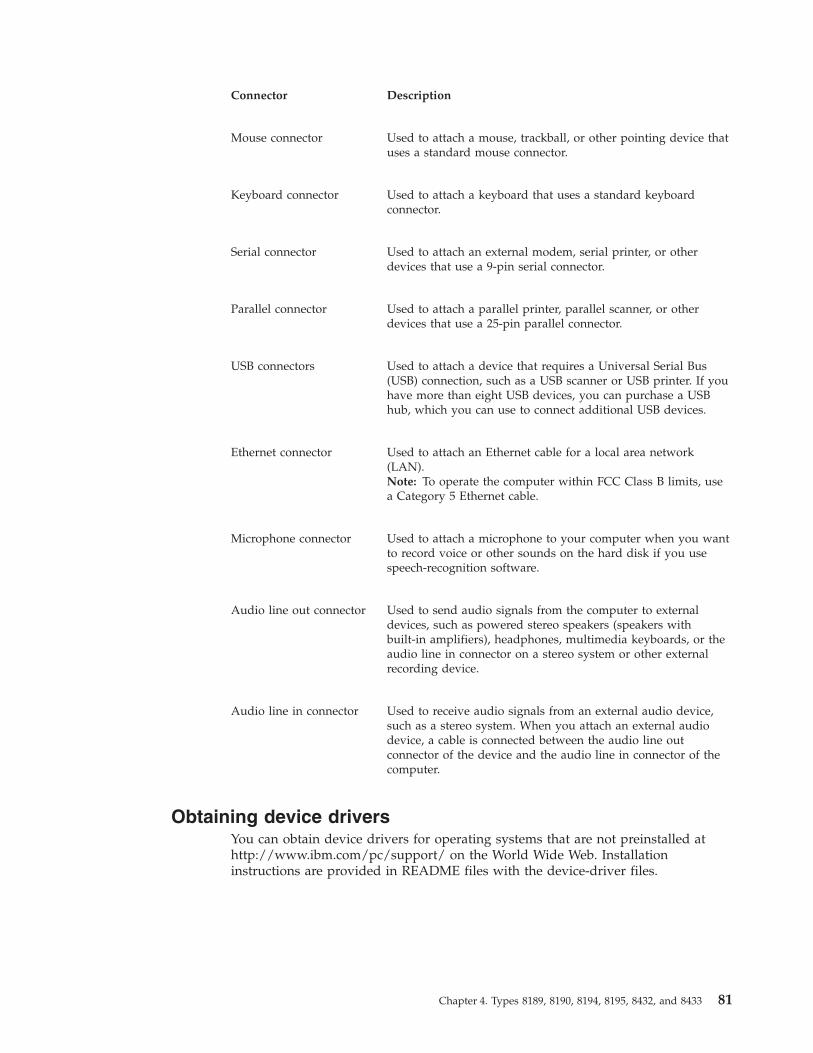
Connector Description
Mouse connector Used to attach a mouse, trackball, or other pointing device thatuses a standard mouse connector.
Keyboard connector Used to attach a keyboard that uses a standard keyboardconnector.
Serial connector Used to attach an external modem, serial printer, or otherdevices that use a 9-pin serial connector.
Parallel connector Used to attach a parallel printer, parallel scanner, or otherdevices that use a 25-pin parallel connector.
USB connectors Used to attach a device that requires a Universal Serial Bus(USB) connection, such as a USB scanner or USB printer. If youhave more than eight USB devices, you can purchase a USBhub, which you can use to connect additional USB devices.
Ethernet connector Used to attach an Ethernet cable for a local area network(LAN).Note: To operate the computer within FCC Class B limits, usea Category 5 Ethernet cable.
Microphone connector Used to attach a microphone to your computer when you wantto record voice or other sounds on the hard disk if you usespeech-recognition software.
Audio line out connector Used to send audio signals from the computer to externaldevices, such as powered stereo speakers (speakers withbuilt-in amplifiers), headphones, multimedia keyboards, or theaudio line in connector on a stereo system or other externalrecording device.
Audio line in connector Used to receive audio signals from an external audio device,such as a stereo system. When you attach an external audiodevice, a cable is connected between the audio line outconnector of the device and the audio line in connector of thecomputer.
Obtaining device driversYou can obtain device drivers for operating systems that are not preinstalled athttp://www.ibm.com/pc/support/ on the World Wide Web. Installationinstructions are provided in README files with the device-driver files.
Chapter 4. Types 8189, 8190, 8194, 8195, 8432, and 8433 81
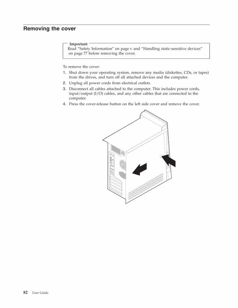
Removing the cover
ImportantRead “Safety Information” on page v and “Handling static-sensitive devices”on page 77 before removing the cover.
To remove the cover:1. Shut down your operating system, remove any media (diskettes, CDs, or tapes)
from the drives, and turn off all attached devices and the computer.2. Unplug all power cords from electrical outlets.3. Disconnect all cables attached to the computer. This includes power cords,
input/output (I/O) cables, and any other cables that are connected to thecomputer.
4. Press the cover-release button on the left side cover and remove the cover.
82 User Guide

Locating componentsThe following illustration will help you locate the various components in yourcomputer.
�1�Microprocessor and heat sink �4�PCI adapter�2�DIMMs �5�Power supply�3�AGP slot
Identifying parts on the system boardThe system board (sometimes called the planar or motherboard) is the main circuitboard in your computer. It provides basic computer functions and supports avariety of devices that are IBM-installed or that you can install later.
Chapter 4. Types 8189, 8190, 8194, 8195, 8432, and 8433 83

The following illustration shows the locations of parts on the system board.
�1� Microprocessor �11� SATA 2 IDE connector�2� DIMM connector 1 �12� Promise of value (POV) daughter card
(some models)�3� DIMM connector 2 �13� Clear CMOS/Recovery jumper�4� DIMM connector 3 �14� Battery�5� DIMM connector 4 �15� SCSI LED connector�6� Power connector �16� PCI slots�7� Diskette drive connector �17� Front panel audio connector�8� PATA primary IDE connector �18� CD-ROM audio connector�9� PATA secondary IDE connector �19� AGP slot�10�SATA 1 IDE connector
Installing memoryYour computer has four connectors for installing dual inline memory modules(DIMMs) that provide up to a maximum of 4.0 GB of system memory.
When installing DIMMs, the following rules apply:v System memory is divided into two channels (channel A and B). DIMM
connectors 1 and 2 are channel A, and DIMM connectors 3 and 4 are channel B.v If DIMM connectors 1 and 3 (or 2 and 4) are filled with the same technology and
size of memory, the system operates in dual channel mode.v Use 2.5 V, 184-pin, 333 MHz double data rate synchronous dynamic random
access memory (DDR SDRAM).v Use 128 MB, 256 MB, 512 MB or 1 GB (when available) DIMMs in any
combination.v DIMMs are 25.4 mm (1.0 inch) in height.
Note: Only DDR SDRAM DIMMs can be used.
84 User Guide
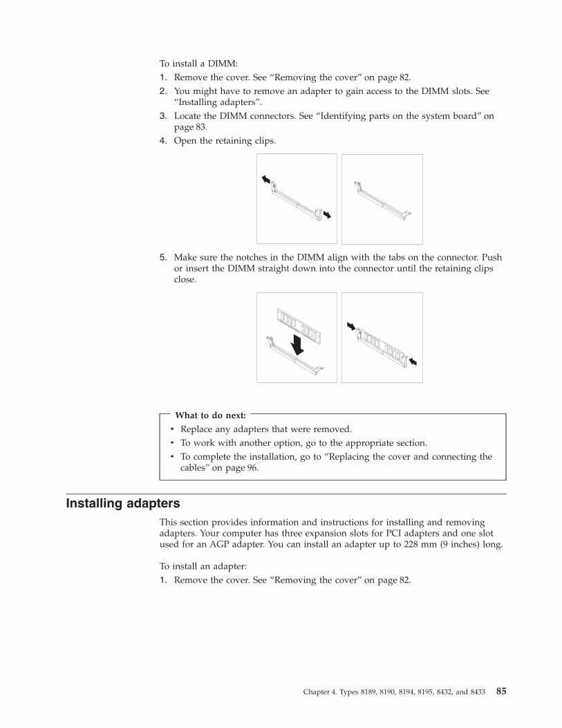
To install a DIMM:1. Remove the cover. See “Removing the cover” on page 82.2. You might have to remove an adapter to gain access to the DIMM slots. See
“Installing adapters”.3. Locate the DIMM connectors. See “Identifying parts on the system board” on
page 83.4. Open the retaining clips.
5. Make sure the notches in the DIMM align with the tabs on the connector. Pushor insert the DIMM straight down into the connector until the retaining clipsclose.
What to do next:
v Replace any adapters that were removed.v To work with another option, go to the appropriate section.v To complete the installation, go to “Replacing the cover and connecting the
cables” on page 96.
Installing adaptersThis section provides information and instructions for installing and removingadapters. Your computer has three expansion slots for PCI adapters and one slotused for an AGP adapter. You can install an adapter up to 228 mm (9 inches) long.
To install an adapter:1. Remove the cover. See “Removing the cover” on page 82.
Chapter 4. Types 8189, 8190, 8194, 8195, 8432, and 8433 85

2. Remove the adapter-slot-cover latch and the slot cover for the appropriateexpansion slot.
3. Remove the adapter from its static-protective package.4. Install the adapter into the appropriate slot on the system board.5. Install the adapter-slot-cover latch.
What to do next
v To work with another option, go to the appropriate section.v To complete the installation, go to “Replacing the cover and connecting the
cables” on page 96.
86 User Guide

Installing internal drivesThis section provides information and instructions for installing and removinginternal drives.
Internal drives are devices that your computer uses to read and store data. You canadd drives to your computer to increase storage capacity and to enable yourcomputer to read other types of media. Some of the different drives that areavailable for your computer are:v Parallel Advanced Technology Attachment (PATA) hard disk drivesv Serial ATA hard disk drivesv CD drives or DVD drivesv Removable media drives
Note: These different drives are also referred to as integrated drive electronics(IDE) drives.
Internal drives are installed in bays. In this book, the bays are referred to as bay 1,bay 2, and so on.
When you install an internal drive, it is important to note what type and size ofdrive that you can install in each bay. Also, it is important to correctly connect theinternal drive cables to the installed drive.
Drive specificationsYour computer comes with the following IBM-installed drives:v A CD drive or DVD drive in bay 1 (some models)v A 3.5-inch diskette disk drive in bay 3v A 3.5-inch hard drive in bay 4
Any bay that does not have a drive installed has a static shield and bay panelinstalled.
Chapter 4. Types 8189, 8190, 8194, 8195, 8432, and 8433 87

The following illustration shows the locations of the drive bays.
The following list describes some of the drives you can install in each bay andtheir height requirements:
�1�Bay 1 - Maximum height: 43.0 mm (1.7 in.) CD drive or DVD drive (preinstalled insome models)5.25-inch hard disk drive
�2�Bay 2 - Maximum height: 43.0 mm (1.7 in.) 5.25-inch hard disk drive3.5-inch hard disk drive (requires amounting bracket)CD driveDVD drive
�3�Bay 3 - Maximum height: 25.8 mm (1.0 in.) 3.5-inch hard disk drive�4�Bay 4 - Maximum height: 25.8 mm (1.0 in.) 3.5-inch diskette drive (preinstalled)�5�Bay 5 - Maximum height: 25.8 mm (1.0 in.) Hard disk drive (preinstalled)
Notes:
1. Drives that are greater than 43.0 mm (1.7 in.) high cannot be installed.2. Install removable media (tape or CD) drives in the accessible bays (bay 1 or 2).
Installing a driveTo install an internal drive, follow these steps:1. Remove the cover. See “Removing the cover” on page 82.2. If your computer has a CD drive or DVD drive, you might need to remove the
signal and power cables from the drive.3. Remove the bay panel from the drive bay by inserting a flat-blade screwdriver
at the end and gently prying it loose.
88 User Guide
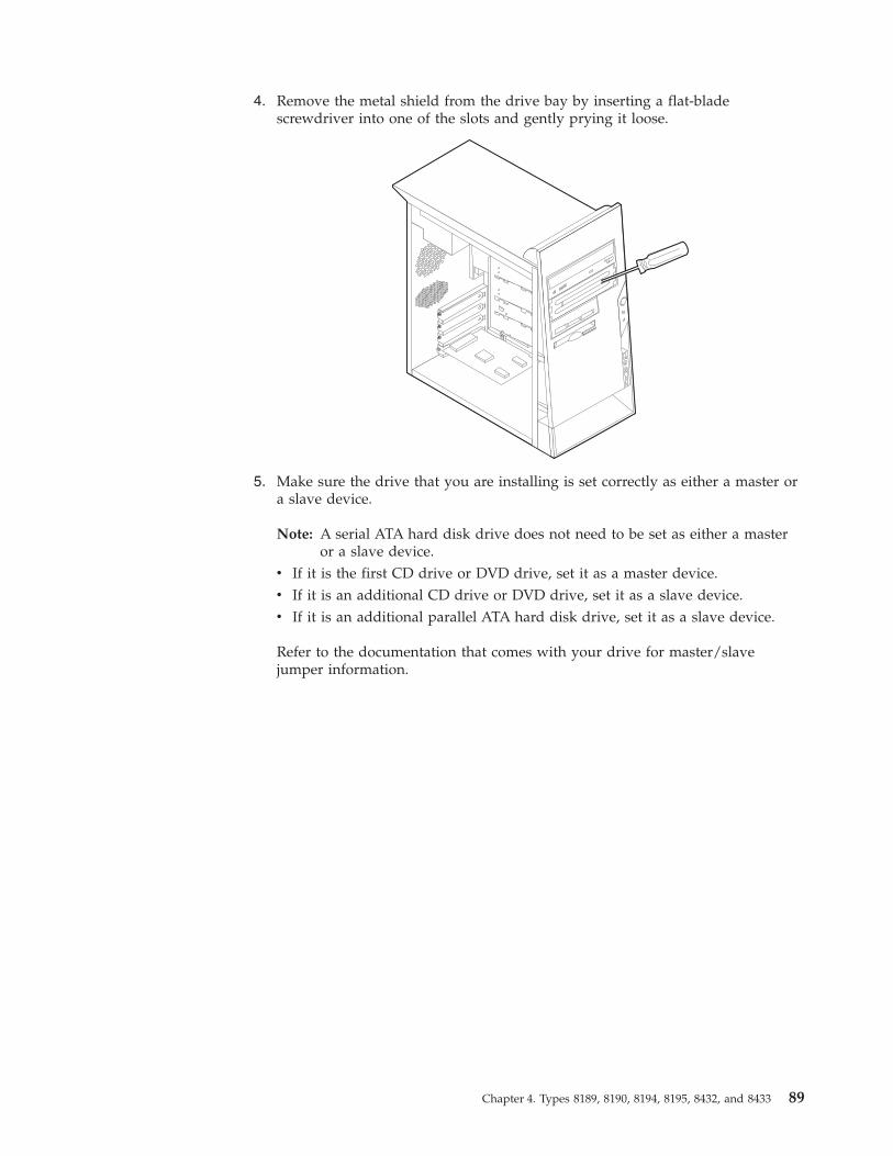
4. Remove the metal shield from the drive bay by inserting a flat-bladescrewdriver into one of the slots and gently prying it loose.
5. Make sure the drive that you are installing is set correctly as either a master ora slave device.
Note: A serial ATA hard disk drive does not need to be set as either a masteror a slave device.
v If it is the first CD drive or DVD drive, set it as a master device.v If it is an additional CD drive or DVD drive, set it as a slave device.v If it is an additional parallel ATA hard disk drive, set it as a slave device.
Refer to the documentation that comes with your drive for master/slavejumper information.
Chapter 4. Types 8189, 8190, 8194, 8195, 8432, and 8433 89
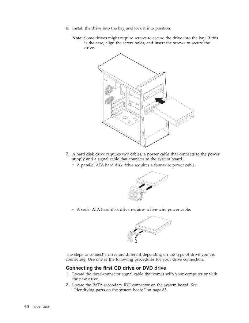
6. Install the drive into the bay and lock it into position.
Note: Some drives might require screws to secure the drive into the bay. If thisis the case, align the screw holes, and insert the screws to secure thedrive.
7. A hard disk drive requires two cables; a power cable that connects to the powersupply and a signal cable that connects to the system board.v A parallel ATA hard disk drive requires a four-wire power cable.
v A serial ATA hard disk drive requires a five-wire power cable.
The steps to connect a drive are different depending on the type of drive you areconnecting. Use one of the following procedures for your drive connection.
Connecting the first CD drive or DVD drive1. Locate the three-connector signal cable that comes with your computer or with
the new drive.2. Locate the PATA secondary IDE connector on the system board. See
“Identifying parts on the system board” on page 83.
90 User Guide

3. Connect one end of the signal cable to the drive and the other to the PATAsecondary IDE connector on the system board. To reduce electronic noise, usethe connectors at the end of the cable only.
4. Your computer has extra power connectors for additional drives. Connect apower connector to the drive.
5. If you have a CD-ROM audio cable, connect it to the drive and to the systemboard. See “Identifying parts on the system board” on page 83.
Connecting an additional CD drive, DVD drive, or parallel ATAhard disk driveAn additional drive can be connected to either the PATA primary IDE or PATAsecondary IDE connector.1. Locate an available PATA IDE connector on the three-connector signal cable
attached to either the PATA primary IDE or PATA secondary IDE connector onthe system board. See “Identifying parts on the system board” on page 83.
2. Connect the extra connector in the signal cable to the new drive.3. Your computer has extra power connectors for additional drives. Connect a
power connector to the drive.
Connecting a serial ATA hard disk driveA serial hard disk drive can be connected to either the SATA 1 IDE or SATA 2 IDEconnector.1. Locate the signal cable that comes with the new drive.2. Locate an available SATA IDE connector on the system board. See “Identifying
parts on the system board” on page 83.3. Connect one end of the signal cable to the drive and the other to an available
SATA IDE connector on the system board.4. Your computer has extra power connectors for additional drives. Connect a
power connector to the drive.
What to do next
v To work with another option, go to the appropriate section.v To complete the installation, go to “Replacing the cover and connecting the
cables” on page 96.
Installing security featuresTo help prevent hardware theft and unauthorized access to your computer, severalsecurity lock options are available. The following sections will help you identifyand install the various types of locks that might be available for your computer. Inaddition to physical locks, unauthorized use of your computer can be prevented bya software lock that locks the keyboard until a correct password is typed in.
Make sure that any security cables you install do not interfere with other computercables.
Chapter 4. Types 8189, 8190, 8194, 8195, 8432, and 8433 91
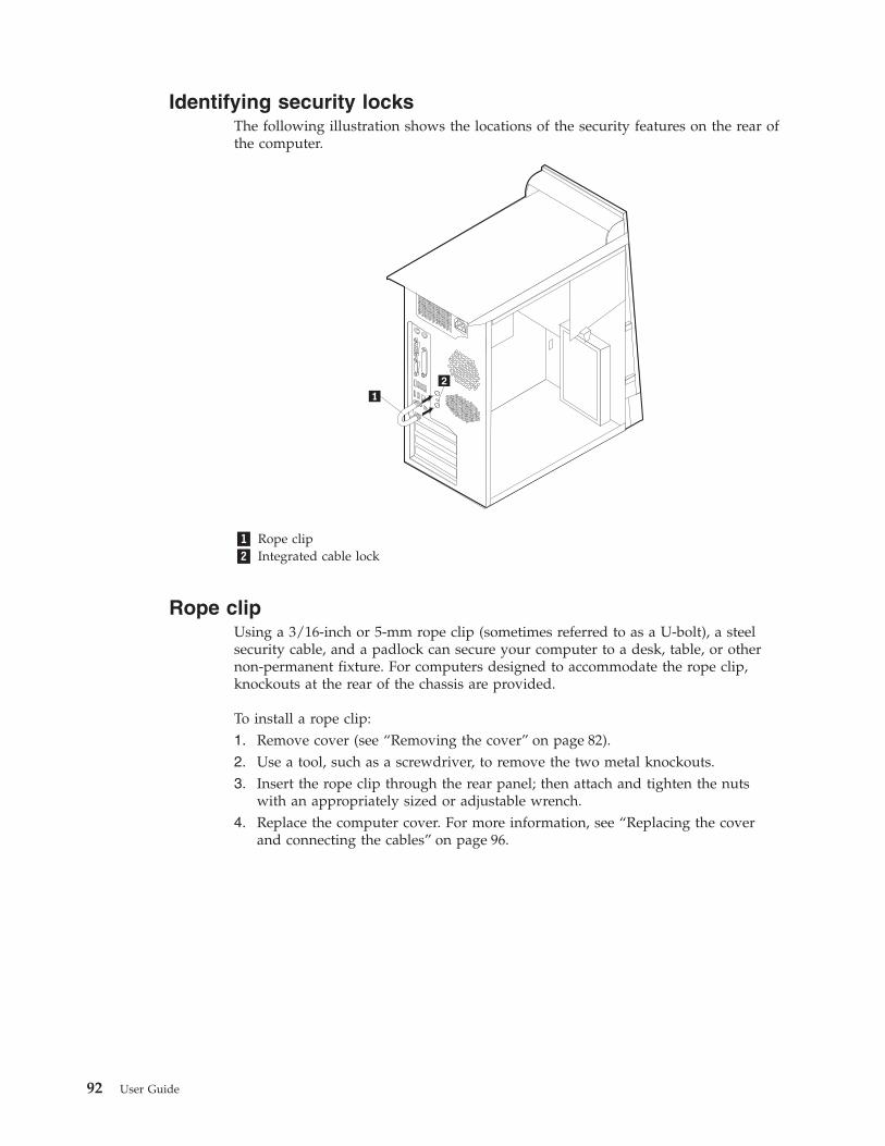
Identifying security locksThe following illustration shows the locations of the security features on the rear ofthe computer.
�1� Rope clip�2� Integrated cable lock
Rope clipUsing a 3/16-inch or 5-mm rope clip (sometimes referred to as a U-bolt), a steelsecurity cable, and a padlock can secure your computer to a desk, table, or othernon-permanent fixture. For computers designed to accommodate the rope clip,knockouts at the rear of the chassis are provided.
To install a rope clip:1. Remove cover (see “Removing the cover” on page 82).2. Use a tool, such as a screwdriver, to remove the two metal knockouts.3. Insert the rope clip through the rear panel; then attach and tighten the nuts
with an appropriately sized or adjustable wrench.4. Replace the computer cover. For more information, see “Replacing the cover
and connecting the cables” on page 96.
92 User Guide
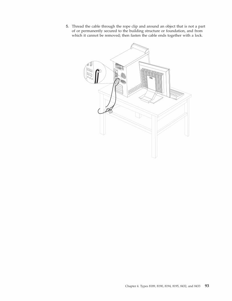
5. Thread the cable through the rope clip and around an object that is not a partof or permanently secured to the building structure or foundation, and fromwhich it cannot be removed; then fasten the cable ends together with a lock.
®®
Chapter 4. Types 8189, 8190, 8194, 8195, 8432, and 8433 93
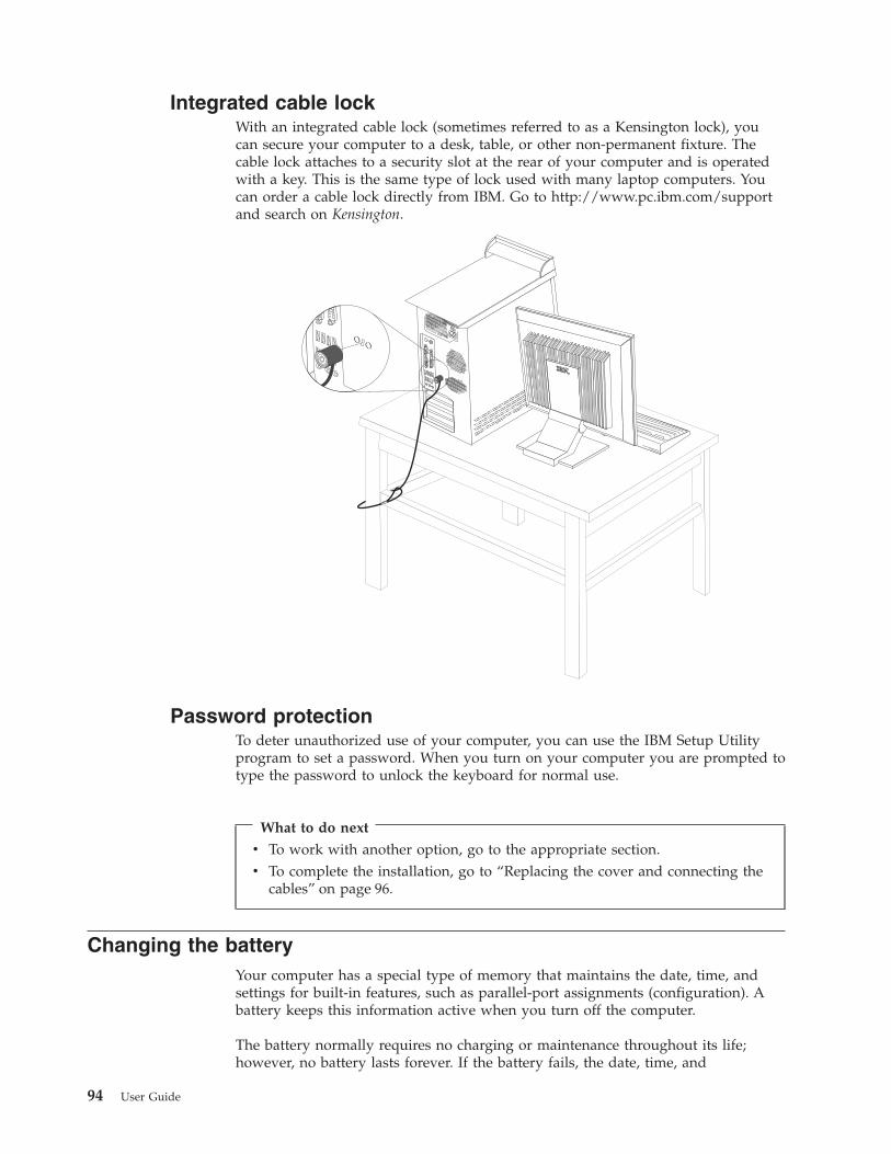
Integrated cable lockWith an integrated cable lock (sometimes referred to as a Kensington lock), youcan secure your computer to a desk, table, or other non-permanent fixture. Thecable lock attaches to a security slot at the rear of your computer and is operatedwith a key. This is the same type of lock used with many laptop computers. Youcan order a cable lock directly from IBM. Go to http://www.pc.ibm.com/supportand search on Kensington.
®
Password protectionTo deter unauthorized use of your computer, you can use the IBM Setup Utilityprogram to set a password. When you turn on your computer you are prompted totype the password to unlock the keyboard for normal use.
What to do next
v To work with another option, go to the appropriate section.v To complete the installation, go to “Replacing the cover and connecting the
cables” on page 96.
Changing the batteryYour computer has a special type of memory that maintains the date, time, andsettings for built-in features, such as parallel-port assignments (configuration). Abattery keeps this information active when you turn off the computer.
The battery normally requires no charging or maintenance throughout its life;however, no battery lasts forever. If the battery fails, the date, time, and
94 User Guide

configuration information (including passwords) are lost. An error message isdisplayed when you turn on the computer.
Refer to “Lithium battery notice” on page vi for information about replacing anddisposing of the battery.
To change the battery:1. Turn off the computer and all attached devices.2. Remove the cover. See “Removing the cover” on page 82.3. Locate the battery. See “Identifying parts on the system board” on page 83.4. If necessary, remove any adapters that impede access to the battery. See
“Installing adapters” on page 85 for more information.5. Remove the old battery.
6. Install the new battery.
7. Replace any adapters that were removed to gain access to the battery. See“Installing adapters” on page 85 for instructions for replacing adapters.
8. Replace the cover, and plug in the power cord. See “Replacing the cover andconnecting the cables” on page 96.
Note: When the computer is turned on for the first time after batteryreplacement, an error message might be displayed. This is normal afterreplacing the battery.
9. Turn on the computer and all attached devices.10. Use the IBM Setup Utility program to set the date and time and any
passwords. See Chapter 5, “Using the IBM Setup Utility program”, on page 99.
Erasing a lost or forgotten password (clearing CMOS)This section applies to lost or forgotten passwords. For more information aboutlost or forgotten passwords, see Access IBM on your desktop.
Note: Some computer models might have a POV daughter card installed on thesystem board. If this is the case, the password is stored in an EEPROM onthe POV card and can not be erased. See “Identifying parts on the systemboard” on page 83 for the location of the POV daughter card.
To erase a forgotten password:1. Turn off the computer and all attached devices.2. Remove the cover. See “Removing the cover” on page 82.
Chapter 4. Types 8189, 8190, 8194, 8195, 8432, and 8433 95
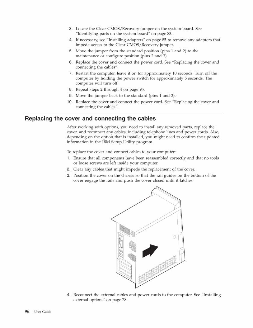
3. Locate the Clear CMOS/Recovery jumper on the system board. See“Identifying parts on the system board” on page 83.
4. If necessary, see “Installing adapters” on page 85 to remove any adapters thatimpede access to the Clear CMOS/Recovery jumper.
5. Move the jumper from the standard position (pins 1 and 2) to themaintenance or configure position (pins 2 and 3).
6. Replace the cover and connect the power cord. See “Replacing the cover andconnecting the cables”.
7. Restart the computer, leave it on for approximately 10 seconds. Turn off thecomputer by holding the power switch for approximately 5 seconds. Thecomputer will turn off.
8. Repeat steps 2 through 4 on page 95.9. Move the jumper back to the standard (pins 1 and 2).
10. Replace the cover and connect the power cord. See “Replacing the cover andconnecting the cables”.
Replacing the cover and connecting the cablesAfter working with options, you need to install any removed parts, replace thecover, and reconnect any cables, including telephone lines and power cords. Also,depending on the option that is installed, you might need to confirm the updatedinformation in the IBM Setup Utility program.
To replace the cover and connect cables to your computer:1. Ensure that all components have been reassembled correctly and that no tools
or loose screws are left inside your computer.2. Clear any cables that might impede the replacement of the cover.3. Position the cover on the chassis so that the rail guides on the bottom of the
cover engage the rails and push the cover closed until it latches.
4. Reconnect the external cables and power cords to the computer. See “Installingexternal options” on page 78.
96 User Guide

5. To update the configuration, see Chapter 5, “Using the IBM Setup Utilityprogram”, on page 99.
Important:When the power cord is first plugged in, the computer might appear to turnon for a few seconds and then turn off. This is a normal sequence to enablethe computer to initialize.
Chapter 4. Types 8189, 8190, 8194, 8195, 8432, and 8433 97

98 User Guide

Chapter 5. Using the IBM Setup Utility program
The IBM Setup Utility program is stored in the electrically erasable programmableread-only memory (EEPROM) of your computer. The IBM Setup Utility program isused to view and change the configuration settings of your computer, regardless ofwhich operating system you are using. However, the operating-system settingsmight override any similar settings in the IBM Setup Utility program.
Starting the IBM Setup Utility programTo start the IBM Setup Utility program, do the following:1. If your computer is already on when you start this procedure, shut down the
operating system and turn off the computer.2. Turn on the computer and look for the following prompt on the logo screen:
(To interrupt normal startup, press Enter)
Press Enter when you see the prompt.3. When the Access IBM Predesktop Area displays, double click Start setup
utility.
Note: If an administrator password has been set, the IBM Setup Utilityprogram menu is not displayed until you type your password. See“Using passwords” for more information.
The IBM Setup Utility might start automatically when POST detects that hardwarehas been removed or new hardware has been installed in your computer.
Viewing and changing settingsThe IBM Setup Utility program menu lists items that identify system configurationtopics.
When working with the IBM Setup Utility program menu, you must use thekeyboard. The keys used to perform various tasks are displayed at the bottom ofeach screen.
Exiting from the IBM Setup Utility programWhen you finish viewing or changing settings, press Esc to return to the IBMSetup Utility program menu (you might have to press Esc several times). If youwant to save the new settings, select Save Settings before you exit. Otherwise,your changes will not be saved.
Using passwordsYou can use passwords to provide security for your computer and data. There aretwo kinds of passwords: a user password and an administrator password. You donot have to set a password of either type to use your computer. However, if youdecide to set either one, read the following sections.
© Copyright IBM Corp. 2003 99

User passwordThe user password feature deters unauthorized persons from gaining access toyour computer.
Administrator passwordSetting an administrator password deters unauthorized persons from changingconfiguration settings. If you are responsible for maintaining the settings of severalcomputers, you might want to set an administrator password.
After you set an administrator password, a password prompt is displayed eachtime you try to access the IBM Setup Utility program. If you type the wrongpassword, you will see an error message. If you type the wrong password threetimes, you must turn the computer off and start again.
If both the user and administrator passwords are set, you can type eitherpassword. However, to change any configuration settings, you must use youradministrator password.
Setting, changing, and deleting a passwordTo set, change, or delete a password, do the following:
Note: A password can be any combination of up to seven characters (A- Z, a-z,and 0-9).
1. Start the IBM Setup Utility program (see “Starting the IBM Setup Utilityprogram” on page 99).
2. From the IBM Setup Utility program menu, select Security.3. Select Set Passwords. Read the information displayed on the right side of the
screen.
Security settings for Access IBM Predesktop AreaThe security settings in the IBM Setup Utility allow you to select the level ofsecurity that you require for the Access IBM Predesktop Area. These setting aredescribed below:
SecureThis setting does not allow any user or software initiated changes.
NormalThis setting allows the user to make changes but the contents are hiddenfrom the operating system.
DisabledThis setting provides the lowest level of security. The area can be changedby the user or the operating system.
To set the security level for the Access IBM Predesktop Area, do the following:1. Start the IBM Setup Utility program (see “Starting the IBM Setup Utility
program” on page 99).2. From the IBM Setup Utility program menu, select Security.3. Select Access IBM Predesktop Area.4. Select the desired setting and press Enter.5. Return to the IBM Setup Utility program menu and select Exit and then Save
Settings or Save and exit the Setup Utility.
100 User Guide
Note: If you do not want to save the settings, select Exit the Setup Utilitywithout saving.
Using Security Profile by DeviceSecurity Profile by Device is used to enable or disable user access to the followingdevices:
IDE controller When this feature is set to Disable, all devices connected to theIDE controller (such as hard disk drives or the CD-ROM drive)are disabled and will not be displayed in the systemconfiguration.
Diskette Drive Access When this feature is set to Disable, the diskette drive cannot beaccessed.
Diskette Write Protect When this feature is set to Enable, all diskettes are treated as ifthey are write-protected.
To set Security Profile by Device, do the following:1. Start the IBM Setup Utility program (see “Starting the IBM Setup Utility
program” on page 99).2. From the IBM Setup Utility program menu, select Security.3. Select Security Profile by Device.4. Select the desired devices and settings and press Enter.5. Return to the IBM Setup Utility program menu and select Exit and then Save
Settings.
Using IDE Drives SetupIn addition to listing the different IDE devices, there are options for configuringthe serial and parallel IDE controllers.
Parallel ATA This setting allows the user to disable one or both of the parallelIDE controllers.
Serial ATA This setting allows the user to disable the serial ATA controllers.Native Mode Operation This setting is only available when the serial ATA controller is
enabled. This allows the user to specify whether the parallel andserial ATA controllers will operate in ″legacy″ or ″native″ mode.By default, they will operate in native mode unless both parallelATA controllers are populated and a serial ATA drive is present.Then the serial ATA drive will become ″native″ mode. The usercan select Automatic or the serial ATA controller to run in″native″ mode. However, running in ″native″ mode might notwork with older operating systems.
To configure IDE Drives Setup, do the following:1. Start the IBM Setup Utility program (see “Starting the IBM Setup Utility
program” on page 99).2. From the IBM Setup Utility program menu, select Devices.3. Select IDE Drives Setup.4. Select the desired devices and settings and press Enter.5. Return to the IBM Setup Utility program menu and select Exit and then Save
Settings.
Chapter 5. Using the IBM Setup Utility program 101
Selecting a startup deviceIf your computer does not start up (boot) from a device such as the CD-ROM,diskette, or hard disk as expected, use one of the following procedures to select astartup device.
Selecting a temporary startup deviceUse this procedure to startup from any boot device.
Note: Not all CDs, hard disks, and diskettes are startable (bootable).1. Turn off your computer.2. Turn on your computer and look for the following prompt on the logo screen:
(To interrupt normal startup, press Enter)
Press Enter when you see the prompt.3. When the Access IBM Predesktop Area displays, select Startup.4. Double click the desired startup device from the Alternate startup devices
menu to begin.
Note: Selecting a startup device from the Alternate startup devices menu does notpermanently change the startup sequence.
Changing the startup sequenceTo view or change the primary or automatic power-on startup sequence, do thefollowing:1. Start the IBM Setup Utility program (see “Starting the IBM Setup Utility
program” on page 99).2. Select Startup.3. Select Startup Sequence. See the information displayed on the right side of the
screen.4. Select the sequence of devices for the Primary Startup Sequence, the Automatic
Startup Sequence, and the Error Startup Sequence.5. Select Exit from the IBM Setup Utility menu and then Save Settings.
If you have changed these settings and want to return to the default settings, selectLoad Default Settings on the Exit menu.
Advanced settingsOn some computer models, the Advanced settings menu includes a setting toEnable/Disable HyperThreading. This feature works only withHyperThreading-aware operating systems such as Microsoft Windows XP. Thedefault setting for HyperThreading is Enabled. However, if you select Set Defaults(HyperThreading is Enabled) and are using an operating system other thanWindows XP, your computer performance might be degraded. Therefore, youshould always set HyperThreading to disabled unless you are sure your operatingsystem supports hyperthreading.
102 User Guide

Appendix A. Updating system programs
This appendix contains information about updating system programs and how torecover from a POST/BIOS update failure.
System programsSystem programs are the basic layer of software that is built into your computer.They include the power-on self-test (POST), the basic input/output system (BIOS)code, and the IBM Setup Utility program. POST is a set of tests and proceduresthat is performed each time you turn on your computer. BIOS is a layer ofsoftware that translates instructions from other layers of software into electricalsignals that the computer hardware can understand. You can use the IBM SetupUtility program to view and change the configuration and setup of your computer.
Your computer system board has a module called electrically erasable programmableread-only memory (EEPROM, also referred to as flash memory). You can easily updatePOST, BIOS, and the IBM Setup Utility program by starting your computer using aflash update diskette or by running a special update program from your operatingsystem.
IBM might make changes and enhancements to the system programs. Whenupdates are released, they are available as downloadable files on the World WideWeb (see the Quick Reference). Instructions for using the system program updatesare available in a .txt file that is included with the update files. For most models,you can download either an update program to create a system-program-update(flash) diskette or an update program that can be run from the operating system.
Updating (flashing) BIOS from a diskette1. Insert a system program update (flash) diskette into the diskette drive (drive A)
in your computer. System program updates are available athttp://www.ibm.com/pc/support/ on the World Wide Web.
2. Turn on the computer. If it is on already, you must turn it off and back onagain. The update begins.
Updating (flashing) BIOS from your operating system
Note: Due to constant improvements being made to the IBM Web site, Web pagecontent (including the links referenced in the following procedure) is subjectto change.
1. From your browser, type http://www.pc.ibm.com/support in the address fieldand press Enter.
2. Locate the Downloadable files for your machine type.3. Under Select your product, choose your machine type and click Go.4. In Downloadable file by category, click BIOS.5. Under Download files - BIOS by date, click your machine type.6. Scroll down and look for a .txt file that has instructions for Flash BIOS update
from the operating system. Click the .txt file.7. Print these instructions. This is very important since they are not on the screen
after the download begins.
© Copyright IBM Corp. 2003 103

8. From your browser, Click Back to return to the list of files. Carefully follow theprinted instructions to download, extract, and install the update.
Recovering from a POST/BIOS update failureIf power to your computer is interrupted while POST/BIOS is being updated (flashupdate), your computer might not restart correctly. If this happens, perform thefollowing procedure (also known as a Boot-block Recovery):1. Turn off the computer and any attached devices, such as printers, monitors,
and external drives.2. Unplug all power cords from electrical outlets, and remove the cover. See
Removing the cover in the chapter for your model.3. Locate the Clear CMOS/Recovery jumper on the system board. See
Identifying parts on the system board in the chapter for your model type.4. If necessary, refer to Installing adapters to remove any adapters that impede
access to the Clear CMOS/Recovery jumper.5. Move the jumper from the standard position (pins 1 and 2) to pins 2 and 3.6. Replace the cover. See Replacing the cover and connecting the cables in the
chapter for your model type.7. Reconnect the power cords for the computer and monitor to electrical outlets.8. Insert the POST/BIOS update (flash) diskette into drive A, and turn on the
computer and the monitor.9. After the update session is completed, there will be no video and the series of
beeps will end. Remove the diskette from the diskette drive, and turn off thecomputer and monitor.
10. Unplug the power cords from electrical outlets.11. Remove the cover. See Removing the cover in the chapter for your model
type.12. Remove any adapters that impede access to the BIOS Configuration jumper.13. Replace the Clear CMOS/Recovery jumper to its original position.14. Replace any adapters that were removed.15. Replace the cover and reconnect any cables that were disconnected.16. Turn on the computer to restart the operating system.
104 User Guide

Appendix B. Cleaning the mouse
This appendix provides instructions on how to clean your mouse. The procedurewill be different depending on which type of mouse you have.
Cleaning an optical mouseIf you experience some problems with your optical mouse, check the following:1. Turn the mouse over and look carefully at the lens area.
a. If there is a smudge on the lens, gently clean the area with a plain cottonswab or plain q-tip.
b. If there is some debris in the lens, gently blow the debris away from thearea.
2. Check the surface you are using the mouse on. If you have a very intricatepicture or pattern beneath the mouse it is difficult for the digital signalprocessor (DSP) to determine changes in the mouse position.
Cleaning a mouse with a ballIf the pointer on the screen does not move smoothly with the mouse, you mightneed to clean the mouse.
Note: The following illustration might be slightly different from your mouse.
�1� Retainer ring�2� Ball�3� Plastic rollers�4� Ball cage
To clean a mouse with a ball:1. Turn off your computer.2. Turn the mouse over, with the top side down, and look carefully at the bottom.
Twist the retainer ring�1�to the unlocked position to remove the ball.
© Copyright IBM Corp. 2003 105

3. Place your hand over the retainer ring and ball�2�, and then turn the mouseover, top side up, so that the retainer ring and ball fall out into your hand.
4. Wash the ball in warm, soapy water then dry it with a clean cloth. Blow aircarefully into the ball cage�4�to dislodge dust and lint.
5. Look for a build up of dirt on the plastic rollers�3�inside the ball cage. Thisbuild up usually appears as a stripe running across the middle of the rollers.
6. If the rollers are dirty, clean them by using a cotton swab soaked in isopropyl(rubbing) alcohol. Turn the rollers with your finger and continue swabbingthem until all the dirt is removed. Be sure the rollers are still centered in theirchannels after you clean them.
7. Remove any fibers from the swab that might be remaining on the rollers.8. Replace the ball and the retainer ring.9. Turn your computer back on.
106 User Guide

Appendix C. Manual modem commands
The following section lists commands for manually programming your modem.
Commands are accepted by the modem while it is in Command Mode. Yourmodem is automatically in Command Mode until you dial a number and establisha connection. Commands may be sent to your modem from a PC runningcommunication software or any other terminal devices.
All commands sent to the modem must begin with AT and end with ENTER. Allcommands may be typed in either upper or lower case, but not mixed. To makethe command line more readable, spaces may be inserted between commands. Ifyou omit a parameter from a command that requires one, it is just like specifying aparameter of 0.
Example:
ATH [ENTER]
Basic AT commandsIn the following listings, all default settings are printed in bold text.
Command Function
A Manually answer incoming call.
A/ Repeat last command executed. Do notprecede A/ with AT or follow with ENTER.
D_ 0 - 9, A-D, # and *
L last number redial
P pulse dialing
Note: Pulse dialing is not supported forAustralia, New Zealand, Norway, and SouthAfrica.
T touch-tone dialing
W wait for second dial tone
, pause
@ wait for five seconds of silence
! flash
; return to Command Mode after dialing
DS=n Dial one of the four telephone numbers(n=0-3) stored in the modem non-volatilememory.
E_ E0 Commands are not echoed
E1 Commands are echoed
+++ Escape Characters - Switch from Data Modeto Command Mode (T.I.E.S. Command)
H_ H0 Force modem on-hook (hang up)
© Copyright IBM Corp. 2003 107

Command Function
H1 Force modem off-hook (make busy)
Note: H1 command is not supported for Italy
I_ I0 Display product-identification code
I1 Factory ROM checksum test
I2 Internal memory test
I3 Firmware ID
I4 Reserved ID
L_ L0 Low speaker volume
L1 Low speaker volume
L2 Medium speaker volume
L3 High speaker volume
M_ M0 Internal speaker off
M1 Internal speaker on until carrier detected
M2 Internal speaker always on
M3 Internal speaker on until carrier detected andoff while dialing
N_ Included for compatibility only, provides noeffect
O_ O0 Return to Data Mode
O1 Return to Data Mode and initiate an equalizerretrain
P Set Pulse dial as default
Q_ Q0 Modem sends responses
Sr? Read and display value in register r.
Sr=n Set register r to value n (n = 0-255).
T Set Tone Dial as default
V_ V0 Numeric responses
V1 Word responses
W_ W0 Report DTE speed only
W1 Report line speed, error correction protocol,and DTE speed.
W2 Report DCE speed only
X_ X0 Hayes Smartmodem 300 compatibleresponses/blind dialing.
X1 Same as X0 plus all CONNECTresponses/blind dialing
X2 Same as X1 plus dial tone detection
X3 Same as X1 plus busy detection/blind dialing
X4 All responses and dial tone and busy signaldetection
Z_ Z0 Reset and retrieve active profile 0
Z1 Reset and retrieve active profile 1
108 User Guide

Extended AT commands
Command Function
&C_ &C0 Force Carrier Detect Signal High (ON)
&C1 Turn on CD when remote carrier is present
&D_ &D0 Modem ignores the DTR signal
&D1 Modem returns to Command Mode after DTRtoggle
&D2 Modem hangs up, returns to the CommandMode after DTR toggle
&D3 Resets modem after DTR toggle
&F_ &F Recall factory default configuration
&G_ &G0 Guard tone disabled
&G1 Guard tone disabled
&G2 1800 Hz guard tone
&K_ &K0 Disable flow control
&K3 Enable RTS/CTS hardware flow control
&K4 Enable XON/XOFF software flow control
&K5 Enable transparent XON/XOFF flow control
&K6 Enable both RTS/CTS and XON/XOFF flowcontrol
&M_ &M0 Asynchronous operation
&P_ &P0 US setting for off-hook-to-on-hook ratio
&P1 UK and Hong Kong off-hook-to-on-hook ratio
&P2 Same as &P0 setting but at 20 pulses perminute
&P3 Same as &P1 setting but at 20 pulses perminute
&R_ &R0 Reserved
&R1 CTS operates per flow control requirements
&S_ &S0 Force DSR Signal High (ON)
&S1 DSR off in command mode, on in on-linemode
&T_ &T0 Ends test in progress
&T1 Perform Local Analog Loopback Test
&T3 Perform Local Digital Loopback Test
&T4 Grant Remote Digital Loopback Test requestby remote modem
&T5 Deny Remote Digital Loopback Test request
&T6 Perform a Remote Digital Loopback Test
&T7 Perform a Remote Digital Loopback Test andSelf-Test
&T8 Perform Local Analog Loopback Test andSelf-Test
&V &V0 Displays Active and Stored Profiles
Appendix C. Manual modem commands 109

Command Function
&V1 Display Last Connection Statistics
&W_ &W0 Stores the active profile as Profile 0
&W1 Stores the active profile as Profile 1
%E_ %E0 Disable auto-retrain
%E1 Enable auto-retrain
+MS? Displays the current Select Modulationsettings
+MS=? Displays a list of supported Select Modulationoptions
+MS=a,b,c,e,f Select modulation where: a=0, 1, 2, 3, 9, 10, 11,12, 56, 64, 69; b=0-1; c=300-56000; d=300-56000; e=0-1; and f=0-1. A, b, c, d, e, fdefault=12, 1, 300, 56000, 0, 0. Parameter ″a″specifies the modulation protocol desiredwhere: 0=V.21, 1=V.22, 2=V.22bis, 3=V.23,9=V.32, 10=V.32bis, 11=V.34,12=V.90,K56Flex,V.34......,56=K 56Flex,V.90,V.34......, 64=Bell 103, and 69=Bell 212.Parameter ″b″ specifies automode operationswhere: 0=automode disabled, 1= automodeenabled with V.8/V.32 Annex A. Parameter ″c″specifies the minimum connection data rate(300- 56000). Parameter ″d″ specifies themaximum connection rate (300-56000);Parameter ″e″ specifies the codec type (0=Law, and 1=A-Law). Parameter ″f″ specifies″robbed bit″ signaling detection (0=detectiondisabled 1=detection enabled)
MNP/V.42/V.42bis/V.44 commands
Command Function
%C_ %C0 Disable MNP Class 5 and V.42bis data compression
%C1 Enable MNP Class 5 data compression only
%C2 Enable V.42bis data compression only
%C3 Enable MNP Class 5 and V.42bis data compression
&Q_ &Q0 Direct data link only (same as \N1)
&Q5 V.42 data link with fallback options
&Q6 Normal data link only (same as \N0)
+DS44=0, 0 Disable V.44
+DS44=3, 0 Enable V.44
+DS44? Current values
+DS44=? List of support values
110 User Guide
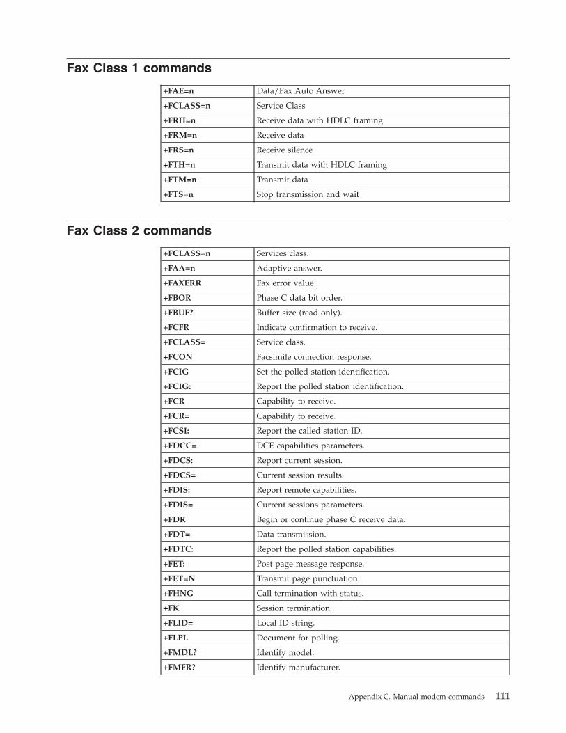
Fax Class 1 commands
+FAE=n Data/Fax Auto Answer
+FCLASS=n Service Class
+FRH=n Receive data with HDLC framing
+FRM=n Receive data
+FRS=n Receive silence
+FTH=n Transmit data with HDLC framing
+FTM=n Transmit data
+FTS=n Stop transmission and wait
Fax Class 2 commands
+FCLASS=n Services class.
+FAA=n Adaptive answer.
+FAXERR Fax error value.
+FBOR Phase C data bit order.
+FBUF? Buffer size (read only).
+FCFR Indicate confirmation to receive.
+FCLASS= Service class.
+FCON Facsimile connection response.
+FCIG Set the polled station identification.
+FCIG: Report the polled station identification.
+FCR Capability to receive.
+FCR= Capability to receive.
+FCSI: Report the called station ID.
+FDCC= DCE capabilities parameters.
+FDCS: Report current session.
+FDCS= Current session results.
+FDIS: Report remote capabilities.
+FDIS= Current sessions parameters.
+FDR Begin or continue phase C receive data.
+FDT= Data transmission.
+FDTC: Report the polled station capabilities.
+FET: Post page message response.
+FET=N Transmit page punctuation.
+FHNG Call termination with status.
+FK Session termination.
+FLID= Local ID string.
+FLPL Document for polling.
+FMDL? Identify model.
+FMFR? Identify manufacturer.
Appendix C. Manual modem commands 111

+FPHCTO Phase C time out.
+FPOLL Indicates polling request.
+FPTS: Page transfer status.
+FPTS= Page transfer status.
+FREV? Identify revision.
+FSPT Enable polling.
+FTSI: Report the transmit station ID.
Voice commands
#BDR Select Baud Rate
#CID Enable Caller ID detection and reporting format
#CLS Select Data, Fax or Voice/Audio
#MDL? Identify Model
#MFR? Identify Manufacturer
#REV? Identify Revision Level
#TL Audio output transmit level
#VBQ? Query Buffer Size
#VBS Bits per sample (ADPCM or PCM)
#VBT Beep Tone Timer
#VCI? Identify Compression Method
#VLS Voice line select
#VRA Ringback goes away timer
#VRN Ringback never came timer
#VRX Voice Receive Mode
#VSDB Silence deletion tuner
#VSK Buffer skid setting
#VSP Silence detection period
#VSR Sampling rate selection
#VSS Silence deletion tuner
#VTD DTMF tone reporting capability
#VTM Enable timing mark placement
#VTS Generate tone signals
#VTX Voice transmit mode
112 User Guide

Attention Switzerland User:If your Swisscom phone line does not have Taxsignal switched OFF, modemfunction may be impaired. The impairment may be resolved by a filter withthe following specifications:
Telekom PTT SCR-BETaximpulssperrfilter-12kHzPTT Art. 444.112.7Bakom 93.0291.Z.N
Appendix C. Manual modem commands 113

114 User Guide

Appendix D. Customer replaceable unit (CRU) parts list
For your computer, the following parts are designated customer replaceable unit(CRU) parts. Refer to the warranty section of your Quick Reference for moreinformation.
CRU parts listAll option and adapter cardsAll bezelsAll keyboardsAll miceAll external speakersAll memoryAll keylocksAll cablesAll hard disk drives, optical drives, and diskette drivesInternal speaker assemblyRFID antennaSpeaker power supplyEMC shield 5.25″Fan assembly, 80 mm, fixed speedInput/output cam bracketPivot lock, 3.5 diskette drivePivot lock, 5.25 DASDRetainer, cards input/outputBattery, 3.0V CMOS batteryControl panel assemblyHard disk drive mounting bracket assemblyFan bracket assemblyAir duct with/without fanPlanar shield kitHard disk drive bracket assemblyHard disk drive tray
© Copyright IBM Corp. 2003 115

116 User Guide

Appendix E. Notices
IBM may not offer the products, services, or features discussed in this document inall countries. Consult your local IBM representative for information on theproducts and services currently available in your area. Any reference to an IBMproduct, program, or service is not intended to state or imply that only that IBMproduct, program, or service may be used. Any functionally equivalent product,program, or service that does not infringe any IBM intellectual property right maybe used instead. However, it is the user’s responsibility to evaluate and verify theoperation of any non-IBM product, program, or service.
IBM may have patents or pending patent applications covering subject matterdescribed in this document. The furnishing of this document does not give youany license to these patents. You can send license inquiries, in writing, to:
IBM Director of LicensingIBM CorporationNorth Castle DriveArmonk, NY 10504-1785U.S.A.
INTERNATIONAL BUSINESS MACHINES CORPORATION PROVIDES THISPUBLICATION “AS IS” WITHOUT WARRANTY OF ANY KIND, EITHEREXPRESS OR IMPLIED, INCLUDING, BUT NOT LIMITED TO, THE IMPLIEDWARRANTIES OF NON-INFRINGEMENT, MERCHANTABILITY OR FITNESSFOR A PARTICULAR PURPOSE. Some jurisdictions do not allow disclaimer ofexpress or implied warranties in certain transactions, therefore, this statement maynot apply to you.
This information could include technical inaccuracies or typographical errors.Changes are periodically made to the information herein; these changes will beincorporated in new editions of the publication. IBM may make improvementsand/or changes in the product(s) and/or the program(s) described in thispublication at any time without notice.
The products described in this document are not intended for use in implantationor other life support applications where malfunction may result in injury or deathto persons. The information contained in this document does not affect or changeIBM product specifications or warranties. Nothing in this document shall operateas an express or implied license or indemnity under the intellectual property rightsof IBM or third parties. All information contained in this document was obtainedin specific environments and is presented as an illustration. The result obtained inother operating environments may vary.
IBM may use or distribute any of the information you supply in any way itbelieves appropriate without incurring any obligation to you.
Any references in this publication to non-IBM Web sites are provided forconvenience only and do not in any manner serve as an endorsement of those Websites. The materials at those Web sites are not part of the materials for this IBMproduct, and use of those Web sites is at your own risk.
© Copyright IBM Corp. 2003 117

Television output noticeThe following notice applies to models that have the factory-installedtelevision-output feature.
This product incorporates copyright protection technology that is protected bymethod claims of certain U.S. patents and other intellectual property rights ownedby Macrovision Corporation and other rights owners. Use of this copyrightprotection technology must be authorized by Macrovision Corporation, and isintended for home and other limited viewing uses only unless otherwiseauthorized by Macrovision Corporation. Reverse engineering or disassembly isprohibited.
TrademarksThe following terms are trademarks of International Business MachinesCorporation in the United States, other countries, or both:
IBMThinkCentreWake on LANPS/2
Microsoft, Windows, and Windows NT are trademarks of Microsoft Corporation inthe United States, other countries, or both.
Intel, Celeron, NetBurst, and Pentium are trademarks of Intel Corporation in theUnited States, other countries, or both.
Other company, product, or service names may be trademarks or service marks ofothers.
118 User Guide

Index
AAccess IBM Predesktop Area, security settings 100adapters
accelerated graphics port (AGP) 5, 27, 51, 77installing
Types 8185, 8186, and 8192 12Types 8187, 8188, and 8193 34Types 8189, 8190, 8194, 8195, 8432, and 8433 85Types 8196 and 8197 60
peripheral component interconnect (PCI) 5, 27, 51, 77slots 12, 34, 60, 85
audio line in connector 8, 30, 55, 81audio line out connector 8, 30, 55, 81audio, subsystem 2, 24, 48, 74
Ccables, connecting 21, 45, 70, 96changing the battery
Types 8185, 8186, and 8192 19Types 8187, 8188, and 8193 43Types 8189, 8190, 8194, 8195, 8432, and 8433 94Types 8196 and 8197 68
cleaning the mouse 105commands
Basic AT 107Extended AT 109Fax Class 1 111Fax Class 2 111MNP/V.42/V.42bis/V.44 110Voice 112
connector descriptionTypes 8185, 8186, and 8192 8Types 8187, 8188, and 8193 30Types 8189, 8190, 8194, 8195, 8432, and 8433 81Types 8196 and 8197 55
coverremoving
Types 8185, 8186, and 8192 9Types 8187, 8188, and 8193 31Types 8189, 8190, 8194, 8195, 8432, and 8433 82Types 8196 and 8197 56
replacingTypes 8185, 8186, and 8192 21Types 8187, 8188, and 8193 45Types 8189, 8190, 8194, 8195, 8432, and 8433 96Types 8196 and 8197 70
Ddevice, drivers 8, 30, 55, 81DIMMs, installing 11, 33, 58, 84drives
bays 2, 14, 24, 36, 48, 62, 74, 87CD 5, 27, 51, 61, 77diskette 5, 27, 51, 77DVD 5, 27, 51, 61, 77hard disk 5, 27, 51, 61, 77installing 15, 37, 62, 88internal 1, 14, 23, 36, 48, 51, 61, 74, 87
drives (continued)removable media 5, 27, 51, 61, 77specifications 14, 36, 62, 87
Eenvironment, operating 4, 26, 50, 76Ethernet connector 8, 30, 55, 81
IIBM Setup Utility 99input/output (I/O)
features 2, 24, 48, 74installing options
Types 8185, 8186, and 8192adapters 12DIMMs 11internal drives 15memory 11security features 17
Types 8187, 8188, and 8193adapters 34DIMMs 33internal drives 37memory 33security features 40
Types 8189, 8190, 8194, 8195, 8432, and 8433adapters 85DIMMs 84internal drives 88memory 84security features 91
Types 8196 and 8197adapters 60DIMMs 58internal drives 62memory 58security features 65
Kkeyboard connector 8, 30, 55, 81
Llocating components
Types 8185, 8186, and 8192 10Types 8187, 8188, and 8193 32Types 8189, 8190, 8194, 8195, 8432, and 8433 83Types 8196 and 8197 57
Mmemory
dual inline memory modules (DIMMs) 11, 33, 58, 84installing 11, 33, 58, 84system 11, 33, 58, 84
microphone connector 8, 30, 55, 81
© Copyright IBM Corp. 2003 119

modemBasic AT commands 107Extended AT commands 109Fax Class 1 commands 111Fax Class 2 commands 111MNP/V.42/V.42bis/V.44 commands 110Voice commands 112
mouse connector 8, 30, 55, 81
Nnoise level 4, 26, 50, 76
Ooptions
available 5, 27, 51, 77external 5, 27, 51, 77internal 5, 27, 51, 77
Pparallel connector 8, 30, 55, 81password
erasing 20, 44, 69, 95lost or forgotten 20, 44, 69, 95setting, changing, deleting 100
physical specificationsTypes 8185, 8186, and 8192 4Types 8187, 8188, and 8193 26Types 8189, 8190, 8194, 8195, 8432, and 8433 76Types 8196 and 8197 50
powerAdvanced Configuration and Power Interface (ACPI)
support 3, 24, 49, 75Advanced Power Management support 2, 24, 49, 75
Rrecovering from a POST/BIOS update failure 104removing the cover
Types 8185, 8186, and 8192 9Types 8187, 8188, and 8193 31Types 8189, 8190, 8194, 8195, 8432, and 8433 82Types 8196 and 8197 56
replacing the coverTypes 8185, 8186, and 8192 21Types 8187, 8188, and 8193 45Types 8189, 8190, 8194, 8195, 8432, and 8433 96Types 8196 and 8197 70
Ssecurity
Access IBM Predesktop Area 100features 3, 17, 24, 40, 65, 75, 91integrated cable lock 19, 43, 68, 94rope clip 17, 41, 66, 92
security profile by device 101serial connector 8, 30, 55, 81system board
connectors 11, 33, 58, 84identifying parts 10, 32, 57, 83location 11, 33, 58, 84memory 5, 11, 27, 33, 51, 58, 77, 84
system programs 103
UUSB connectors 8, 30, 55, 81using, security profile by device 101
Vvideo, subsystem 2, 24, 48, 74
120 User Guide


����
Part Number: 71P6645
Printed in U.S.A.
(1P) P/N: 71P6645