user instructions - flowserve · user instructions installation ... 1.2 user safety safety notices...
TRANSCRIPT

Experience In Motion
USER INSTRUCTIONS
Installation Operation
Maintenance
Limitorque PT SeriesFCD LMENM2001-00 – 01/10
Limitorque PT Series Worm Gear Operator FCD LMENIM2001-00 – 01/10
2
Contents1 Introduction
1.1 Purpose 41.2 User Safety 4
2 Inspection, Installation, and Mounting Procedures 52.1 Initial Inspection and Storage Instructions 62.2 Inspection and Recording 62.3 Storage Procedure 62.4 General Mounting Instructions 72.5 Setting Position Limit Stops for PT 12, 14, 30, 40, 50, 75 82.6 Setting Position Limit Stops PT60 92.7 Setting Position Limit Stops for PT 65, 120, 150 102.8 Setting Position Limit Stops for PT 250, 500, 1000 11
3 Lubrication 124 Disassembly and Reassembly Instructions 13
4.1 Safety Precautions 134.2 Safety Practices 144.3 PT 12, 14, 30, 40 144.4 PT 50, 75 184.5 PT 60 214.6 PT 65, 120, 150 254.7 PT 250, 500, 1000 284.8 Spur Gear Attachments - PT 14, 30, 40 314.9 Spur Gear Attachments - PT 60 344.10 Spur Gear Attachments - PT 65, 120, 150 374.11 Spur Gear Attachments - PT 250, 500, 1000 39
5 How to Order Parts 42
FiguresFigure 2.1 – Typical PT Exploded View 5Figure 2.2 – Setting Position Limit Stops – PT12, 14, 30, 40, 50, 75 8Figure 2.3 – Setting Position Limit Stops – PT60 9Figure 2.4 – Setting Position Limit Stops – PT65, 120, 150 10Figure 2.5 – Setting Position Limit Stops – PT250, 500, 1000 11Figure 4.1-2 – PT12, 14, 30, 40 Disassembly & Reassembly 16Figure 4.3-5 – PT50, 75 Disassembly & Reassembly 20Figure 4.6-7 – PT60 Disassembly & Reassembly 23Figure 4.8-11 – PT65, 120, 150 Disassembly & Reassembly 26-27Figure 4.12-13 – PT250, 500, 1000 Disassembly & Reassembly 30Figure 4.14 – PT14, 30, 40 SGA Disassembly & Reassembly 33Figure 4.15-17 – PT60 SGA Disassembly & Reassembly 35-36Figure 4.18-20 – PT65, 120, 150 SGA Disassembly & Reassembly 37-38Figure 4.21-22 – PT250, 500, 1000 SGA Disassembly & Reassembly 40-41

3
Limitorque PT Series Worm Gear Operator FCD LMENIM2001-00 – 01/10
flowserve.com
TablesTable 2.1 – Stem Adapter Bolt Torques 7Table 3.1 – Lubricants 12Table 4.1 – Parts List – PT12, 14, 30, 40 17Table 4.2 – Parts List – PT50, 75 21Table 4.3 – Parts List – PT60 24Table 4.4 – Parts List – PT65, 120, 150 28Table 4.5 – Parts List – PT250, 500, 1000 31Table 4.6 – Parts List – Spur Gear Attachment – PT14, 30, 40 33Table 4.7 – Parts List – Spur Gear Attachment – PT60 36Table 4.8 – Parts List – Spur Gear Attachment – PT65, 120, 150 39Table 4.9 – Parts List – Spur Gear Attachment – PT250, 500, 1000 41
Limitorque PT Series Worm Gear Operator FCD LMENIM2001-00 – 01/10
4
1 Introduction
1.1 PurposeThe installation and maintenance manual (IOM) explains how to install and maintain the Flowserve Limitorque PT operator. Information on installation, disassembly, reassembly, lubrication, and spare parts is provided.
1.2 User SafetySafety notices in this manual detail precautions the user must take to reduce the risk of personal injury and damage to the equipment. The user must read and be familiar with these instructions before attempting installation, operation, or maintenance. Failure to observe these precautions could result in serious bodily injury, damage to the equipment. voiding of the warranty, or operational difficulty.
Safety notice are presented in this manual in three forms:
c WaRnIng: Refers to personal safety. alerts the user to potential danger. Failure to follow warning notices could result in personal injury or death.
a CaUTIOn: Directs the user’s attention to general precautions that, if not followed, could result in personal injury and/or equipment damage.
nOTE: Highlights information critical to the user’s understanding of the operator’s installation and operation.
5
Limitorque PT Series Worm Gear Operator FCD LMENIM2001-00 – 01/10
flowserve.com
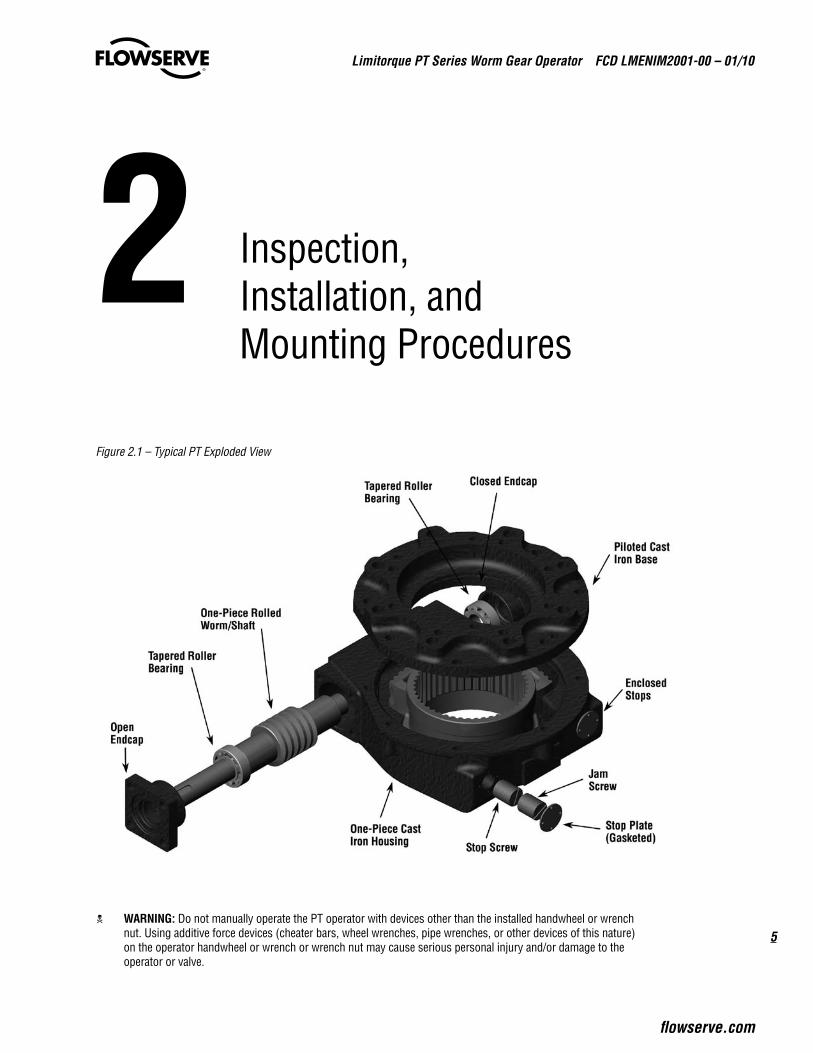
2 Inspection, Installation, and Mounting Procedures
Figure 2.1 – Typical PT Exploded View
trical operation
c WaRnIng: Do not manually operate the PT operator with devices other than the installed handwheel or wrench nut. Using additive force devices (cheater bars, wheel wrenches, pipe wrenches, or other devices of this nature) on the operator handwheel or wrench or wrench nut may cause serious personal injury and/or damage to the operator or valve.
Limitorque PT Series Worm Gear Operator FCD LMENIM2001-00 – 01/10
6
2.1 Initial Inspection and Storage Instructions
c WaRnIng: Read this installation and maintenance manual carefully and completely before attempting to store the operator. If an electric actuator is attached to the PT manual operator, be aware of the electrical hazards. Consult the electric actuator installation and maintenance manual for guidance.
2.2 Inspection and RecordingUpon receipt of the operator, inspect the condition of the equipment, and record nameplate information.
1. Carefully remove operator from shipping carton or skid. Thoroughly examine the equipment for any physical damage that may have occurred during shipment. If damaged, immediately report the damage to the transport company.
2. A nameplate is attached to each operator with the following information:
• Operator size• Assembly position• Order Number• Serial number• Customer tagging
Record this information for future reference, i.e. ordering parts, obtaining further information.
2.3 Storage ProcedurenOTE: The following is the recommended storage procedure to retain maximum product integrity during storage. Failure to comply with recommended procedure will void the warranty.
Storage (less than 1 year)Store operators on wooden skids to protect the machined mounting flange. Place the wooden skids containing the operators in a clean, dry, protected warehouse. If the operators must be stored outside, they must be covered in polyethylene protection with silica get crystals to absorb moisture. If an electric actuator is attached to the PT, refer to the storage procedures in its respective manual for appropriate storage procedures. Rotate input shafts every three months to mix the lubricant.
7
Limitorque PT Series Worm Gear Operator FCD LMENIM2001-00 – 01/10
flowserve.com
2.4 General Mounting Instructions
a CaUTIOn: To avoid the potential for disengaging the worm gear segment, ensure that the pointer cap pointer is oriented to the mid-point of the 90º valve travel. Full stroke rotation of the quadrant should not move the pointer past the corresponding Open or Close ID marks on the housing cover.
1. Place valve in full closed position.
2. Remove the pointer cap from the PT operator. Refer to Section 4 for removal/replacement instructions for the pointer cap.
3. PT12/14/30/40/50/60/75/120/150 – Slide the splined adapter onto the valve shaft and insert the key. Splined adapters include machining for a setscrew to eliminate movement of the splined adapter on the valve shaft.
4. Confirm operator stop alignment before engaging splines. Mount operator on valve and bolt securely.
5. PT65/120/150 – Remove the splined adapter from the PT and mount the PT to the valve. Align the valve shaft with the bore and key of the splined adapter. Using either the PT or electric actuator handwheel, rotate the PT drive sleeve to align the drive sleeve’s splines with the splined adapter. Slide the splined adapter down onto the valve stem and into the drive sleeve of the PT.
nOTE: Blank splined adapters are not machines for set screws.
6. PT250/500/1000 – Stem adapters are bolted into place from the top of the PT. Remove the torque nut and align the valve drive stem with the bore and key of the torque nut. Slide the torque nut onto the valve stem. Using either the PT or electric actuator handwheel, rotate the PT drive sleeve to align the drive sleeve’s threaded holes with the torque nut’s through holes. Bolt the torque nut into position. Preload properly class 8.8 fasteners, securing torque nut as follows at installation. (Preload is not set at factory.)
Table 2.1 – Stem Adapter Bolt Torques Unit Size ft-lb n m
PT250 475 640
PT500 700 950
PT1000 1,200 1,620
Fasteners that are stainless steel or other than property class 8.8 require different preload torque than listed above. Consult factory.
7. Turn PT operator input shaft to full closed position. The stops are preset for 90º travel. Be certain of correct direc-tion of rotation.
Limitorque PT Series Worm Gear Operator FCD LMENIM2001-00 – 01/10
8
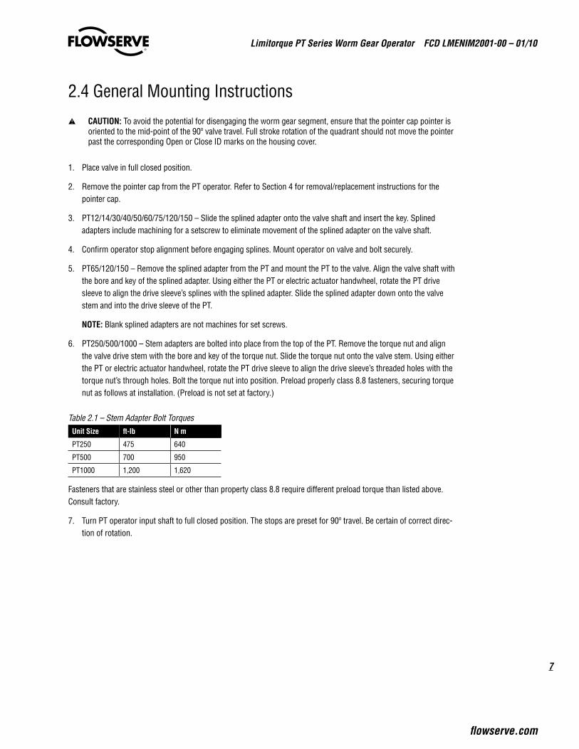
2.5 Setting Position Limit Stops - PT12, 14, 30, 40, 50, 75Refer to Figure 2.2.
1. Remove the two Stop Screw Caps (pc# 10) (if supplied) to expose the Stop Screws (pc# 11).
2. Loosen the Stop Adjusting Nut on the Stop Screw and adjust the screw by turning it counterclockwise to back the screw away from the Worm Gear Quadrant (pc# 12)
3. Place the valve disk in the full closed position
4. Turn the Stop Screw (pc# 11) in the clockwise direction until the end of the screw contacts the Worm Gear Quadrant (pc# 12)
5. Tighten the Stop Adjusting Nut to secure the closed set position
6. Move the valve disk to the full open position
7. Follow steps 2 through 5
a CaUTIOn: If the valve is operated with an electric actuator/gear operator combination, and the valve is position-seated, set the actuator limit switches to trip prior to engagement of the PT Drive Sleeve/Worm Gear with the Stop Screws. Damage to the operator could result from the Drive Sleeve/Worm Gear contacting the Stop Screw under motorized operation.
note: The stops are adjustable to +/- 5º of total travel to allow for proper positioning of the worm gear quadrant.
Figure 2.2 – Setting Position Limit Stops – PT12, 14, 30, 40, 50, 75
11
-
5 50C
03
-
00 1
1009
040506 0208 07
SERIAL No:
FULLY GREASE
DIVISION OF
12 13
02B
16 17 1809B
1412A
15
03
16B
9
Limitorque PT Series Worm Gear Operator FCD LMENIM2001-00 – 01/10
flowserve.com
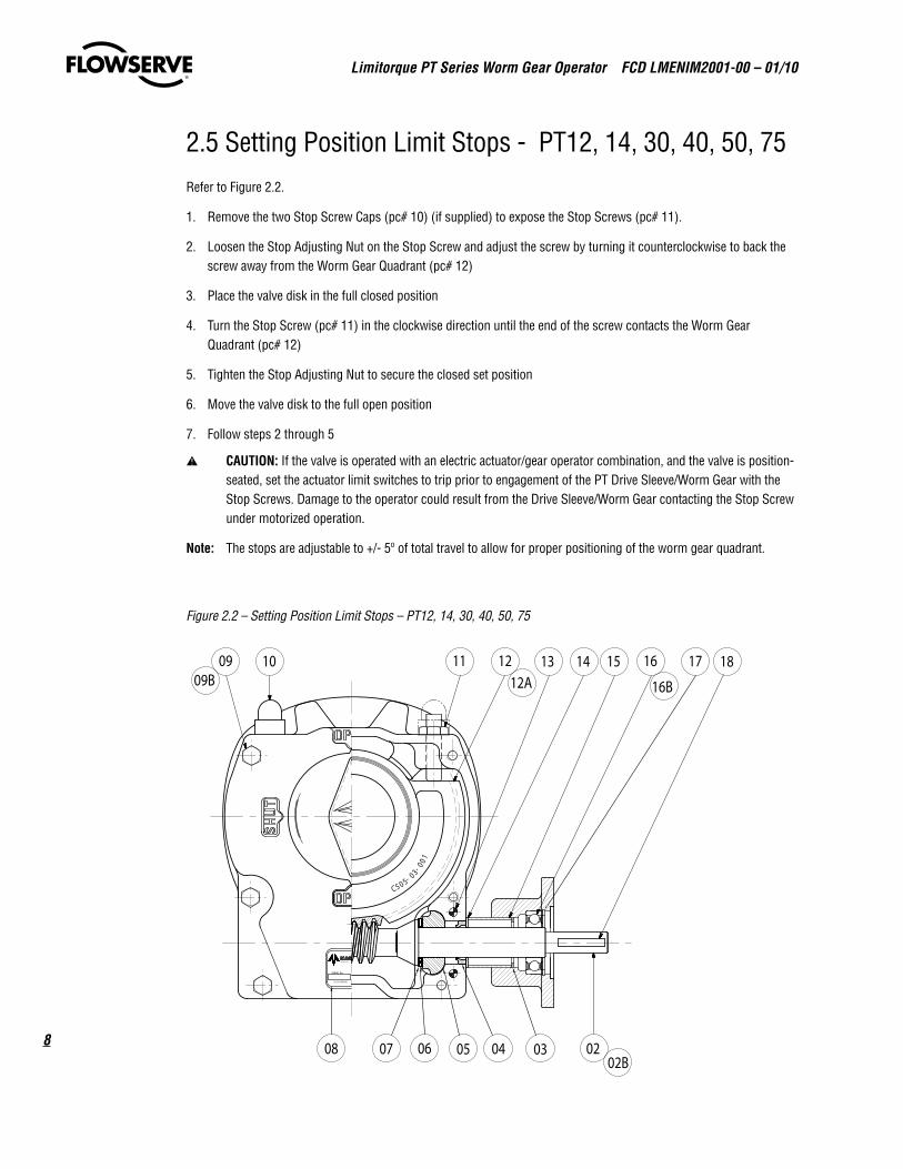
2.6 Setting Position Limit Stops - PT60Refer to Figure 2.3.
1. Loosen the Stop Adjusting Nut (pc# 8)
2. Turn the Stop Adjusting Screw (pc# 7) counterclockwise to back the screw away from the Worm Gear (pc# 19)
3. Place the valve disk in the full closed position (pointer will point to the full closed marking on the Gear Housing, pc# 2)
4. Turn the Stop Adjusting Screw in the clockwise direction until the end of the screw contacts the Worm Gear
5. Tighten the Stop Adjusting Nut to secure the closed set position
6. Move the valve disk to the full open position
7. Follow steps 1 through 5
a CaUTIOn: If the valve is operated with an electric actuator/gear operator combination, and the valve is position-seated, set the actuator limit switches to trip prior to engagement of the PT Worm Gear with the Stop Screws. Damage to the operator could result from the Worm Gear contacting the Stop Screw under motorized operation.
note: The stops are adjustable to +/- 5º of total travel to allow for proper positioning of the worm gear quadrant.
Figure 2.3 – Setting Position Limit Stops – PT60
7
8
11
10
12
6
2
18
19
4
15
17
320
1
9
21

Limitorque PT Series Worm Gear Operator FCD LMENIM2001-00 – 01/10
10
2.7 Setting Position Limit Stops - PT65, 120, 150Refer to Figure 2.4.
1. Remove the Stop Plates (pc# 9) and Stop Plate Gaskets (pc# 10) to expose the Stop Screws (pc# 7)
2. Remove the outboard Stop Screws
3. Turn the inboard Stop Screw counterclockwise to back the screw away from the Drive Sleeve/Worm Gear
4. Place the valve disk in the full closed position (pointer will point to the full closed marking on the Gear Housing)
5. Turn the Stop Screw in the clockwise direction until the end of the screw contacts the Drive Sleeve/Worm Gear
6. Install the outboard Stop Screw and tighten firmly against the inboard Stop Screw to secure the closed set position
7. Move the valve disk to the full open position
8. Follow steps 3 through 6
a CaUTIOn: If the valve is operated with an electric actuator/gear operator combination, and the valve is position-seated, set the actuator limit switches to trip prior to engagement of the PT Drive Sleeve/Worm Gear with the Stop Screws. Damage to the operator could result from the Drive Sleeve/Worm Gear contacting the Stop Screw under motorized operation.
note: The stops are adjustable to +/- 5º of total travel to allow for proper positioning of the worm gear quadrant.
Figure 2.4 – Setting Position Limit Stops – PT65, 120, 150
5
198
23
2
1
7
910
20
6
11
18 3 21

11
Limitorque PT Series Worm Gear Operator FCD LMENIM2001-00 – 01/10
flowserve.com
2.8 Setting Position Limit Stops – PT250, 500, 1000Refer to Figure 2.5.
1. Loosen the Stop Adjusting Nut (pc# 11)
2. Turn the Stop Adjusting Screw (pc# 10) counterclockwise to back the screw away from the Drive Sleeve/Worm Gear (pc# 3)
3. Place the valve disk in the full closed position (pointer will point to the full closed marking on the Gear Housing, pc# 1)
4. Turn the Stop Adjusting Screw in the clockwise direction until the end of the screw contacts the Drive Sleeve/Worm Gear
5. Tighten the Stop Adjusting Nut to secure the closed set position
6. Move the valve disk to the full open position
7. Follow steps 1 through 5
a CaUTIOn: If the valve is operated with an electric actuator/gear operator combination, and the valve is position-seated, set the actuator limit switches to trip prior to engagement of the PT Worm Gear with the Stop Screws. Damage to the operator could result from the Worm Gear contacting the Stop Screw under motorized operation.
note: The stops are adjustable to +/- 5º of total travel to allow for proper positioning of the worm gear quadrant.
Figure 2.5 – Setting Position Limit Stops – PT250, 500, 1000
2X 2.29 ASSEMBLE STOPS
TO THIS DIMENSION
Wormshaft & StopsScale 1 : 3
2515
715
8
9
6
2
6
21
45
17
1311
10
12
22
Limitorque PT Series Worm Gear Operator FCD LMENIM2001-00 – 01/10
12
3 Lubrication
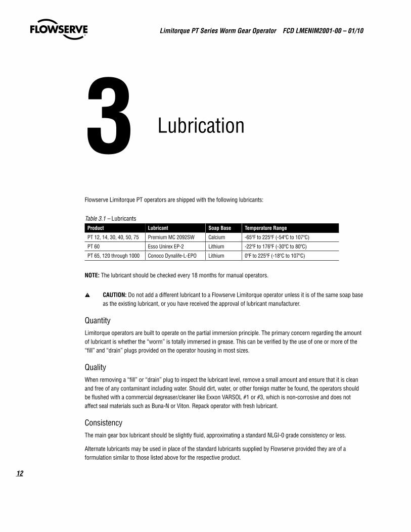
Flowserve Limitorque PT operators are shipped with the following lubricants:
Table 3.1 – Lubricants Product Lubricant Soap Base Temperature Range
PT 12, 14, 30, 40, 50, 75 Premium MC 2092SW Calcium -65ºF to 225ºF (-54ºC to 107ºC)
PT 60 Esso Unirex EP-2 Lithium -22ºF to 176ºF (-30ºC to 80ºC)
PT 65, 120 through 1000 Conoco Dynalife-L-EPO Lithium 0ºF to 225ºF (-18ºC to 107ºC)
nOTE: The lubricant should be checked every 18 months for manual operators.
a CaUTIOn: Do not add a different lubricant to a Flowserve Limitorque operator unless it is of the same soap base as the existing lubricant, or you have received the approval of lubricant manufacturer.
QuantityLimitorque operators are built to operate on the partial immersion principle. The primary concern regarding the amount of lubricant is whether the “worm” is totally immersed in grease. This can be verified by the use of one or more of the “fill” and “drain” plugs provided on the operator housing in most sizes.
QualityWhen removing a “fill” or “drain” plug to inspect the lubricant level, remove a small amount and ensure that it is clean and free of any contaminant including water. Should dirt, water, or other foreign matter be found, the operators should be flushed with a commercial degreaser/cleaner like Exxon VARSOL #1 or #3, which is non-corrosive and does not affect seal materials such as Buna-N or Viton. Repack operator with fresh lubricant.
ConsistencyThe main gear box lubricant should be slightly fluid, approximating a standard NLGI-0 grade consistency or less.
Alternate lubricants may be used in place of the standard lubricants supplied by Flowserve provided they are of a formulation similar to those listed above for the respective product.
13
Limitorque PT Series Worm Gear Operator FCD LMENIM2001-00 – 01/10
flowserve.com
4 Disassembly and Reassembly Instructions
4.1 Safety Precautions
c WaRnIng: Read this Installation, Operation and Maintenance Manual carefully and completely before attempting to install, operate, or troubleshoot the Limitorque operator.
c WaRnIng: Potential HIGH PRESSURE vessel — be aware of high-pressure hazards associated with the attached valve or other actuated device when installing or performing maintenance on the operator. Do not remove the operator mounting bolts from the valve or actuated device unless the valve or device stem is secured or there is no pressure in the line.
c WaRnIng: For maintenance and/or disassembly of the operator while installed on the valve, ensure that the operator is not under thrust or torque load. If the valve must be left in service, the valve stem must be locked in such a way as to prevent any movement of the valve stem.
c WaRnIng: Do not manually operate the operator with devices other than the installed handwheel. Using force beyond the ratings of the operator and/or using additive force devices such as cheater bars, wheel wrenches, pipe wrenches, or other devices on the operator handwheel may cause serious personal injury and/or damage to the operator and valve.
c WaRnIng: Do not exceed any design limitations or make modifications to this equipment without first consulting Limitorque.
c WaRnIng: Use of this product must be suspended any time it fails to operate properly.
a CaUTIOn: If a motor actuator is driving the manual operator, do not operate the valve under motor operation without first checking and setting the limit switch and checking for correct motor rotation.
a CaUTIOn: Do not use replacement parts that are not genuine Flowserve Limitorque parts, as serious personal injury and/or damage to the operator and valve may result.
Limitorque PT Series Worm Gear Operator FCD LMENIM2001-00 – 01/10
14
4.2 Safety Practices The following check points should be performed to maintain safe operation of the PT gear operator:
• Set up a periodic operating schedule on infrequently used valves.
• Ensure that the limit and/or torque switches on any electric actuator fitted to the PT worm gear operator are correctly and appropriately adjusted.
4.3 PT12, 14, 30, 40Refer to Figures 4.1, 4.2 and Table 4.1.
1. Remove the Key (pc# 18) from the Worm Shaft (pc# 2) assembly.
2. Remove the plastic Indicator Cap (pc# 19) by applying equal pressure underneath the cap, on opposite sides of the cap, and prying upward.
note: The metal Indicator Cap is removed by removing the two screws that attach the Indicator Cap to the Quadrant.
3. Remove the Flange Cover Hex Head Screws (pc# 9)
4. Turn the operator onto its side and tap on the Quadrant (pc# 12) and flange of the Cover (pc# 1) to separate the Cover, Worm Shaft (pc# 2) assembly, and Quadrant from the Gearcase (pc# 21).
Caution: Use a soft-headed mallet to prevent damage to the Quadrant bore and keyways.
Caution: Care should be taken to prevent the Quadrant and Worm Shaft assembly from completely disengaging from the Gearcase.
note: The Flange Cover will not separate from the Gearcase without adequate force to overcome and clear the dowel pin connections between the Flange Cover and Gearcase.
5. Return the operator to the upright position.
6. With the Quadrant free from the base of the Gearcase, lift the Cover, Quadrant, and Worm Shaft assembly from the Gearcase and slide the Worm Shaft assembly away from the Quadrant.
7. Remove the Quadrant from the Gearcase.
8. Slide the Worm Shaft assembly out of the Flange Cover.
note: If additional disassembly is required, please follow the steps below:
9. Remove the Snap Ring (pc# 17) and tap out the Input Bearing (pc# 16) from the Cover.
note: The Smalley Retaining Ring (pc# 3) and Protection Sleeve (pc# 15) can be removed if required. Remove the Protection Sleeve by tapping it out of the Flange Cover.
10. Remove Thrust Washers (pc# 7), Thrust Bearings (pc# 6), Worm Shaft Bearings (pc# 5), and Oil Seal (pc# 4) as required.

15
Limitorque PT Series Worm Gear Operator FCD LMENIM2001-00 – 01/10
flowserve.com
Reassembly Instructions:
1. Tap the Dowel pins (pc# 13) flush with the Flange Cover (pc# 1).
2. If the Worm Shaft components have been removed, reassemble the Worm Shaft (pc# 2) with the Thrust Washers (pc# 7), Thrust Bearings (pc# 6), Worm Shaft Bearings (pc# 5), and Oil Seal (pc# 4).
note: The Oil Seal should be located near the end of the Worm Shaft to facilitate installing the assembly into the Gearcase (pc# 21).
3. Lower the Quadrant (pc# 12), with the wording up, and the Worm Shaft (pc# 2) assembly, with the dashes on the Worm Shaft Bearings facing up, into the Gearcase simultaneously.
Caution: The O-Ring (pc# 22) on the lower Quadrant journal seals the Gearcase / Quadrant interface. Check the condi-tion of the O-Ring. If damaged, replace it.
4. Mesh the gearing on the Quadrant with the Worm on the Worm Shaft and slide into the Gearcase.
5. Repack the gearing area with lubricant, thoroughly immersing the Worm/Worm Gear interface and Bearings.
6. Apply Loctite 574 or equivalent around the Oil Seal and slide the Oil Seal down the Worm Shaft and into the Gearcase.
7. Apply a bead of Loctite 574 or equivalent on the machined surface and around the bolt holes of the Gearcase, being careful to avoid applying Loctite into the bolt holes.
8. Prior to installing the Flange Cover (pc# 1), place the Protective Sleeve Seal (pc# 14) against the Oil Seal.
9. Slide the Cover over the Worm Shaft and place onto the Gearcase.
10. Tap down the Dowel pins (pc# 13) in the two holes that are not tapped so that they are flush with the Flange Cover.
11. Install the Flange Cover screws.
12. Attach the Indicator Cap (pc# 19) to the Quadrant (pc# 12) noting the location of the nub on the inside of the plastic Indicator Cap that sets in one of the drilled holes in the Quadrant.
note: The cast iron Indicator Cap is attached with two screws.
Caution: Check that the Indicator Cap is installed to correctly reflect the position of the Quadrant relative to valve position.
13. Ensure that the Protection Sleeve (pc# 15) is against the Protection Sleeve Seal. Use the Smalley Retaining Ring (pc# 3) to push the Protection Sleeve against the Protection Sleeve Seal if needed.
14. Place the Input Bearing (pc# 16) and Snap Ring (pc# 17) over the Worm Shaft and into the Motor Flange of the Cover.
15. Re-insert the Key in the Worm Shaft.
16. Check the operator for proper operation. The Worm Shaft should be capable of operation by hand. Stroke through a complete open-close cycle.

Limitorque PT Series Worm Gear Operator FCD LMENIM2001-00 – 01/10
16
Figure 4.1 – PT12, 14, 30, 40 Disassembly & Reassembly
Figure 4.2 – PT12, 14, 30, 40 Disassembly & Reassembly
11
-5 50C
03-
00 1
1009
040506 0208 07
SERIAL No:
FULLY GREASE
DIVISION OF
12 13
02B
16 17 1809B
1412A
15
03
16B
22
01
2019 21

17
Limitorque PT Series Worm Gear Operator FCD LMENIM2001-00 – 01/10
flowserve.com
Table 4.1 – Parts List – PT12, 14, 30, 40Piece # Description
1 Cover
2 Motorized Worm Shaft
3 Smalley Retaining Ring
4 Oil Seal
5 Worm Shaft Bearing
6 Thrust Bearing
7 Thrust Washer
9 Hex Head Screw
10 Stop Screw Cap
11 Stop Screw Kit
12 Quadrant
13 Dowel
14 Protection Sleeve Seal
15 Protection Sleeve
16 Input Bearing
17 Snap Ring
18 Key
19 Indicator Cap
20 Indicator Cap O-Ring
21 Gearcase
22 Quadrant O-Ring
23 Hex Head Screw (not shown)
24 Lockwasher (not shown)
25 Splined Adapter (not shown)
Limitorque PT Series Worm Gear Operator FCD LMENIM2001-00 – 01/10
18
4.4 PT50, 75Refer to Figure 4.3, 4.4, 4.5 and Table 4.2
1. Remove the Key (pc# 6) from the Motorized Pinion (pc# 8).
2. Remove the plastic Indicator Cap (pc# 12) by applying equal pressure underneath the cap, on opposite sides of the cap, and prying upward.
note: The metal Indicator Cap is removed by removing the two screws that attach the Indicator Cap to the Quadrant (pc# 9).
3. Remove the Cover Screws (pc# 13)
4. Turn the operator onto its side and tap on the Quadrant (pc# 9) to separate the Flanged Cover (pc# 14) from the Gearcase (pc# 2).
Caution: Use a soft-headed mallet to prevent damage to the Quadrant bore and keyways.
note: The Flanged Cover will not separate from the Gearcase without adequate force to overcome the Dowels (pc# 18) connecting the Flanged Cover and Gearcase.
5. Return the operator to the upright position
6. Remove the Flanged Cover (pc# 14) with Motorized Pinion (pc# 6) and Bearings.
7. With the Quadrant free from the base of the Gearcase, lift the Quadrant and Worm Shaft assembly from the Gearcase and slide the Worm Shaft assembly away from the Quadrant and out of the Gearcase.
8. Remove the Quadrant from the Gearcase.
note: If additional disassembly is required, please follow the steps below:
9. Slide the Motorized Pinion and Pinion Shaft Bearings (pc# 7) assembly out of the Flanged Cover by lifting the rear bearing until it clears the bearing recess and tapping on the outboard end of the pinion shaft. .
10. Remove the Circlip (pc# 22) and tap out the Bearing from the inboard side of the Flanged Cover.
note: The Smalley Retaining Ring (pc# 23) and Protection Sleeve (pc# 24) can be removed from the Flanged Cover if required. Remove the Protection Sleeve by tapping it out of the Flanged Cover.
11. Remove the Circlip (pc# 20) from the Worm Shaft
12. Remove the Spur Wheel
note: The Worm Shaft Bearings (pc# 17) are press-fitted to the Worm Shaft. Removal will require a gear puller or similar device.
Reassembly Instructions:
1. If the Worm Shaft (pc# 16) components have been removed, reassemble the Worm Shaft with the Worm Shaft Bearings (pc# 17), Spur Wheel (pc# 19), and Circlip (pc# 20).
2. Lower the Quadrant (pc# 9), with the wording up, and the Worm Shaft assembly, into the Gearcase simultaneously.
Caution: The O-Ring (pc# 1) on the lower Quadrant journal seals the Gearcase / Quadrant interface. Check the condi-tion of the O-Ring. If damaged, replace it.
3. Mesh the gearing on the Quadrant with the Worm on the Worm Shaft and slide into the Gearcase.
19
Limitorque PT Series Worm Gear Operator FCD LMENIM2001-00 – 01/10
flowserve.com
4. Mount the Motorized Pinion (pc# 8) and Bearing assembly into the Gearcase.
note: The Oil Seal should be located near the end of the Motorized Pinion (pc# 8) to facilitate installing the assembly into the Gearcase (pc# 2).
5. Repack the gearing area with lubricant, thoroughly immersing the Worm/Worm Gear, Worm Shaft Bearings, and Spur Wheel/Motorized Pinion.
6. Apply Loctite 574 or equivalent around the Oil Seal and slide the Oil Seal down the Motorized Pinion (pc# 8) and into the Gearcase.
7. Apply a bead of Loctite 574 or equivalent on the machined surface and around the bolt holes of the Gearcase, being careful to avoid applying Loctite into the bolt holes.
8. Reinstall the Flanged Cover Bearing by seating it into the Flanged Cover from the outboard end of the Cover.
9. Install the Circlip (pc# 22).
10. Prior to installing the Flanged Cover place the Protection Sleeve Seal (pc# 25) against the Oil Seal.
11. Slide the Flanged Cover over the Worm Shaft and place onto the Gearcase.
12. Tap down the Cover Dowels (pc# 18), in the two holes in the Gearcase that are not tapped so that they are flush with the Flanged Cover.
13. Install the Flanged Cover screws.
14. Attach the Indicator Cap (pc# 12) to the Quadrant (pc# 9) noting the location of the nub on the inside of the plastic Indicator Cap that sets in one of the drilled holes in the Quadrant.
Caution: Check the condition of the o-ring in the Indicator Cap. If worn or damaged, replace it.
Caution: Check that the Indicator Cap is installed to correctly reflect the position of the Quadrant relative to the valve position.
note: The cast iron Indicator Cap is attached with two screws.
15. Ensure that the Protection Sleeve (pc# 24) is against the Protection Sleeve Seal (pc# 25). Use the Smalley Retaining Ring (pc# 23) to push the Protection Sleeve against the Protection Sleeve Seal if needed.
16. Place the Flanged Cover Bearing and Snap Ring (pc# 17) over the Motorized Pinion (pc# 8) and into the Flanged Cover.
17. Re-insert the Key (pc# 6) in the Motorized Pinion (pc# 8).
18. Check the operator for proper operation. The Worm Shaft should be capable of operation by hand. Stroke through a complete open-close cycle.
Limitorque PT Series Worm Gear Operator FCD LMENIM2001-00 – 01/10
20
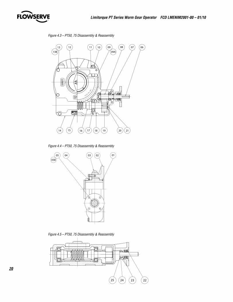
Figure 4.3 – PT50, 75 Disassembly & Reassembly
Figure 4.4 – PT50, 75 Disassembly & Reassembly
Figure 4.5 – PT50, 75 Disassembly & Reassembly
16
00-1
- 0 3
2 05C
17 1918 20 21
070810111213
1514
09
09A
06
13B
05 04 03 02 01
05B
24 222325
21
Limitorque PT Series Worm Gear Operator FCD LMENIM2001-00 – 01/10
flowserve.com
Table 4.2 – Parts List – PT50, 75
Piece # Description
1 Quadrant O-Ring
2 Gearcase
3 Protection Cap
4 Indicator O-Ring
5 Oil Seal
6 Shaft Key
7 Pinion Shaft Bearing
8 Motorized Pinion
9 Quadrant
10 Socket Set Screw
11 Jam Nut
12 Indicator Cap
13 Cover Screw
14 Flanged Cover
15 Nameplate
16 Worm Shaft
17 Worm Shaft Bearing
18 Cover Dowel
19 Spur Wheel
20 Wheel Circlip
21 Spur Wheel Key
22 Snap Ring
23 Smalley Retaining Ring
24 Protection Sleeve
25 Protection Sleeve Seal
4.5 PT60Refer to Figure 4.6, 4.7 and Table 4.3
1. Remove the Valve Position Indicator (pc# 12) by removing the Indicator Bolts and Lockwashers (pc# 11).
2. Remove the Worm Cover (pc# 10).
3. Replace the Valve Position Indicator so that the center hub and the Segment Gear (pc# 19) maintain their orienta-tion, or scribe a mark across the spline teeth for reassembly later.
4. Remove the Motor Flange (pc# 14) with Bearing Spacer (pc# 9) by removing the Thrust Spacer Bolts (pc# 20).
5. Remove the Thrust Spacer Shims.
note: Retain the Shims as they will be required for reassembly.
6. Pull on the Worm Shaft/Bearing assembly (pc# 3) to move the tapered roller bearing cup forward.
note: The Segment Gear (pc# 19) should be in the mid travel position in the Worm Housing (pc# 2). If the Worm Shaft/Bearing assembly comes forward about 1 inch it will be possible to lift out the Segment Gear. If the Worm Shaft does not come forward, remove the Frost Plug (pc# 17) from the other end of the Gear Housing and tap on the Worm Shaft to release it from the Worm Housing.
Limitorque PT Series Worm Gear Operator FCD LMENIM2001-00 – 01/10
22
7. Remove the Segment Gear from the Worm Housing
8. Remove the Worm Shaft/Bearing assembly from the Worm Housing.
9. Remove Worm Shaft Bearings (pc# 3) from the Worm Shaft/Bearing assembly, if required, with a gear puller or similar device.
Reassembly Instructions:
1. Check the condition of the Motor Flange Bushing (pc# 22), Segment Gear O-Ring (pc# 5), and Face Groove O-Ring (pc# 4). Replace as required.
2. Grease the tapered roller bearings on the Worm Shaft/Bearing assembly (pc# 3) and place the Worm Shaft/Bearing assembly into the Worm Housing (pc# 2) bore, stopping short of engaging the back Roller Bearing Cone.
3. Offset the Worm Shaft/Bearing assembly toward the outside of the Worm Housing so that it is away from the center hub bore.
4. Grease the center hub bore and install the Segment Gear into the Worm Housing.
note: Push the Segment Gear straight into the Worm Housing to avoid cutting the Segment Gear O-Ring (pc# 5).
note: The Segment Gear should be seated on the shoulder in the base of the Worm Housing for PT60 operators with one-piece segments. For operators with a removable bushing, be sure the Valve Position Indicator plate is installed on the Segment Gear until the Worm Cover (pc# 10) is installed so that the valve position is maintained upon reinstallation.
5. Engage the Worm Shaft/Bearing assembly with the Segment Gear and move it inward to engage the Roller Bearing Cone.
6. Slide the other Roller Bearing Cone into the bearing bore and push it forward using the Bearing Spacer (pc# 9). The Worm should now be engaged properly with the Segment Gear.
note: Ensure that the Worm Shaft/Bearing assembly rotates with minimal play. Remove shims until the Worm Shaft/Bearing assembly is tight, then add back one shim to obtain the proper fit.
7. Install the Thrust Spacer Shims (pc# 18) on the Bearing Spacer (pc# 9), engage in the housing bore, and fasten with the Thrust Spacer Bolts (pc# 20).
note: For operators with spur gear attachments, there will be a 1/8 inch gap from the outside of the Worm Housing (pc# 2) to the Bearing Spacer when the Bearing Cone engages. For operators without spur gear attachments, the Thrust Spacer length is built into the Bearing Spacer (pc# 9).
8. Re-lubricate the Worm Housing, focusing on the Worm/Segment Gear interface, while rotating the Worm Shaft/Bearing assembly (pc# 3). Lubricate the top hub of the Segment Gear.
9. Run a bead of silicone around the top edge of the Worm Housing (pc# 2).
10. Place the Worm Cover on the hub and push down straight and even. Install the Worm Cover Bolts (pc# 6) and tighten.
11. Mount the Valve Position Indicator (pc# 12) in the appropriate position relative to the Segment Gear.
12. Check rotation to ensure proper operation. The Worm Shaft/Bearing assembly should be capable of operation by hand. Stroke through a complete open-close cycle.
23
Limitorque PT Series Worm Gear Operator FCD LMENIM2001-00 – 01/10
flowserve.com
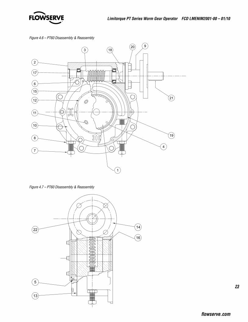
Figure 4.6 – PT60 Disassembly & Reassembly
Figure 4.7 – PT60 Disassembly & Reassembly
7
8
11
10
12
6
2
18
19
4
15
17
320
1
9
21
13
5
14
16
22

Limitorque PT Series Worm Gear Operator FCD LMENIM2001-00 – 01/10
24
Table 4.3 – Spur Gear Attachment Parts List - PT60
Piece # Description
1 Insert Bushing
2 Worm Housing
3 Worm Shaft/Bearing Assembly
4 Face Groove O-Ring
5 Segment Gear O-Ring
6 Worm Cover Bolts
7 Stop Adjusting Screw
8 Adjustment Screw Jam Nut
9 Bearing Spacer
10 Worm Cover
11 Indicator Bolt, Lockwasher, Seal Kit
12 Valve Position Indicator
13 Worm Gasket
14 Motor Flange
15 Worm Cover Locating Pins
16 Insert Bushing O-Ring
17 Frost Plug
18 Thrust Spacer Shims
19 Segment Gear
20 Thrust Spacer Bolts
21 Input Key
22 Motor Flange Bushing
25
Limitorque PT Series Worm Gear Operator FCD LMENIM2001-00 – 01/10
flowserve.com
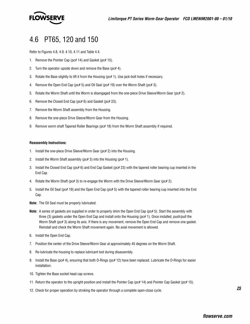
4.6 PT65, 120 and 150Refer to Figures 4.8, 4.9, 4.10, 4.11 and Table 4.4.
1. Remove the Pointer Cap (pc# 14) and Gasket (pc# 15).
2. Turn the operator upside down and remove the Base (pc# 4).
3. Rotate the Base slightly to lift it from the Housing (pc# 1). Use jack-bolt holes if necessary.
4. Remove the Open End Cap (pc# 5) and Oil Seal (pc# 19) over the Worm Shaft (pc# 3).
5. Rotate the Worm Shaft until the Worm is disengaged from the one-piece Drive Sleeve/Worm Gear (pc# 2).
6. Remove the Closed End Cap (pc# 6) and Gasket (pc# 23).
7. Remove the Worm Shaft assembly from the Housing.
8. Remove the one-piece Drive Sleeve/Worm Gear from the Housing.
9. Remove worm shaft Tapered Roller Bearings (pc# 18) from the Worm Shaft assembly if required.
Reassembly Instructions:
1. Install the one-piece Drive Sleeve/Worm Gear (pc# 2) into the Housing.
2. Install the Worm Shaft assembly (pc# 3) into the Housing (pc# 1).
3. Install the Closed End Cap (pc# 6) and End Cap Gasket (pc# 23) with the tapered roller bearing cup inserted in the End Cap.
4. Rotate the Worm Shaft (pc# 3) to re-engage the Worm with the Drive Sleeve/Worm Gear (pc# 2).
5. Install the Oil Seal (pc# 19) and the Open End Cap (pc# 5) with the tapered roller bearing cup inserted into the End Cap.
note: The Oil Seal must be properly lubricated.
note: A series of gaskets are supplied in order to properly shim the Open End Cap (pc# 5). Start the assembly with three (3) gaskets under the Open End Cap and install onto the Housing (pc# 1). Once installed, push/pull the Worm Shaft (pc# 3) along its axis. If there is any movement, remove the Open End Cap and remove one gasket. Reinstall and check the Worm Shaft movement again. No axial movement is allowed.
6. Install the Open End Cap.
7. Position the center of the Drive Sleeve/Worm Gear at approximately 45 degrees on the Worm Shaft.
8. Re-lubricate the housing to replace lubricant lost during disassembly.
9. Install the Base (pc# 4), ensuring that both O-Rings (pc# 12) have been replaced. Lubricate the O-Rings for easier installation.
10. Tighten the Base socket head cap screws.
11. Return the operator to the upright position and install the Pointer Cap (pc# 14) and Pointer Cap Gasket (pc# 15).
12. Check for proper operation by stroking the operator through a complete open-close cycle.
Limitorque PT Series Worm Gear Operator FCD LMENIM2001-00 – 01/10
26
Figure 4.8 – PT65, 120, 150 Disassembly & Reassembly
Figure 4.9 – PT65, 120, 150 Disassembly & Reassembly
A
A
11
1617
5
198
23
2
1
7
910
20
6
11
18 3 21
27
Limitorque PT Series Worm Gear Operator FCD LMENIM2001-00 – 01/10
flowserve.com
Figure 4.10 – PT65, 120, 150 Disassembly & Reassembly
Figure 4.11 – PT65, 120, 150 Disassembly & Reassembly
4
24
12
1315
14
12
B
B
22
Limitorque PT Series Worm Gear Operator FCD LMENIM2001-00 – 01/10
28
Table 4.4 – Parts List – PT65, 120, 150
Piece # Description
1 Housing
2 Drive Sleeve
3 Worm Shaft
4 Base
5 Open End Cap
6 Closed End Cap
7 Stop Screw
8 Key
9 Stop Plate
10 Stop Plate Gasket
11A Hex Head Cap Screw
11B Lockwasher
12A O-Ring
12B O-Ring
13 O-Ring
14 Pointer Cap
15 Pointer Cap Gasket
16 Nameplate
17 Drive Screw
18 Tapered Roller Bearing
19 Oil Seal
20 Socket Head Cap Screw
21 Socket Head Cap Screw
22 Socket Head Cap Screw
23 End Cap Gasket
24 Splined Adapter
25 Motorized Adapter (not shown)
26 Hex Head Cap Screw (not shown)
27 Lockwasher (not shown)
4.7 PT250, 500, 1000Refer to Figures 4.12, 4.13 and Table 4.5.
1. Remove the Pointer Cap (pc# 19).
2. Remove the hex head cap screws that secure the Stem Nut (pc# 18) to the Drive Sleeve/Gear (pc# 3).
3. Attach two eye bolts to the Stem Nut and remove the Stem Nut from the Drive Sleeve/Gear.
4. Remove the blind End Cap (pc# 7) and Worm Shaft Shim Set (pc# 9) from the Housing (pc# 1).
5. Turn the operator upside down and remove the screws from the Base Plate (pc# 13).
6. Insert two eye bolts into the threaded holes in the Base Plate and remove the Base Plate.
7. Remove the open End Cap and Worm Shaft Gasket (pc# 17).

29
Limitorque PT Series Worm Gear Operator FCD LMENIM2001-00 – 01/10
flowserve.com
8. Remove the Tapered Roller Bearing (pc# 6) from the open worm bore.
9. Remove the Tapered Roller Bearing (pc# 6) from the blind worm bore.
10. Attach two eye bolts to the Drive Sleeve/Gear (pc# 3) and remove.
11. Remove the Worm Shaft (pc# 2) from the Housing (pc# 1).
12. Remove the Hex Nut (pc# 11) from the Drive Sleeve Stops (pc# 10) and remove the Stops from the Housing.
Reassembly Instructions:
1. Install the Drive Sleeve Stops (pc# 10) into the Housing (pc# 1) and reattach the Hex Nuts (pc# 11).
2. Insert the Worm Shaft (pc# 2) into the Housing.
3. Attach two eye bolts to the Drive Sleeve/Gear (pc# 3) and install into the Housing.
note: Replace the upper O-Ring (pc# 4) and lower O-Ring (pc# 5) on the Drive Sleeve/Gear (pc# 3). Lubricate the O-Rings for easier installation.
4. Install the Tapered Roller Bearing (pc# 6) and bearing cone for the blind worm bore.
5. Install the Tapered Roller Bearing (pc# 6) and bearing cone for the open End Cap.
6. Install the open End Cap and Worm Shaft Gasket (pc# 17).
7. Re-lubricate the housing to replace lubricant lost during disassembly.
8. Insert two eye bolts into the Base Plate (pc# 13) and install the Base Plate (pc# 13) to the Housing (pc# 1).
note: Ensure that the O-Ring is securely positioned into the groove on the bottom of the Base Plate. Lubricate the O-Ring for easier installation
9. Turn the operator right side up and install the blind Worm Cap (pc# 7) and Worm Shaft Shim Set (pc# 9) on the Housing.
note: Add or subtract shims until there is no excessive play in the Worm Shaft (pc# 2) and the Worm Shaft turns freely.
10. Attach two eye bolts to the Stem Nut (pc# 18) and install into the Drive Sleeve/Gear
11. Install the Pointer Cap.
12. Check the rotation of the Drive Sleeve/Gear through one complete open-close cycle to ensure proper operation.

Limitorque PT Series Worm Gear Operator FCD LMENIM2001-00 – 01/10
30
Figure 4.12 – PT250, 500, 1000 Disassembly & Reassembly
Figure 4.13 – PT250, 500, 1000 Disassembly & Reassembly
SECTION A-A
DrivesleeveSCALE 1 : 3
19
15
3
1318
4
5
14
20
2X 2.29 ASSEMBLE STOPS
TO THIS DIMENSION
Wormshaft & StopsScale 1 : 3
2515
715
8
9
6
2
6
21
45
17
111
10
12
22
31
Limitorque PT Series Worm Gear Operator FCD LMENIM2001-00 – 01/10
flowserve.com
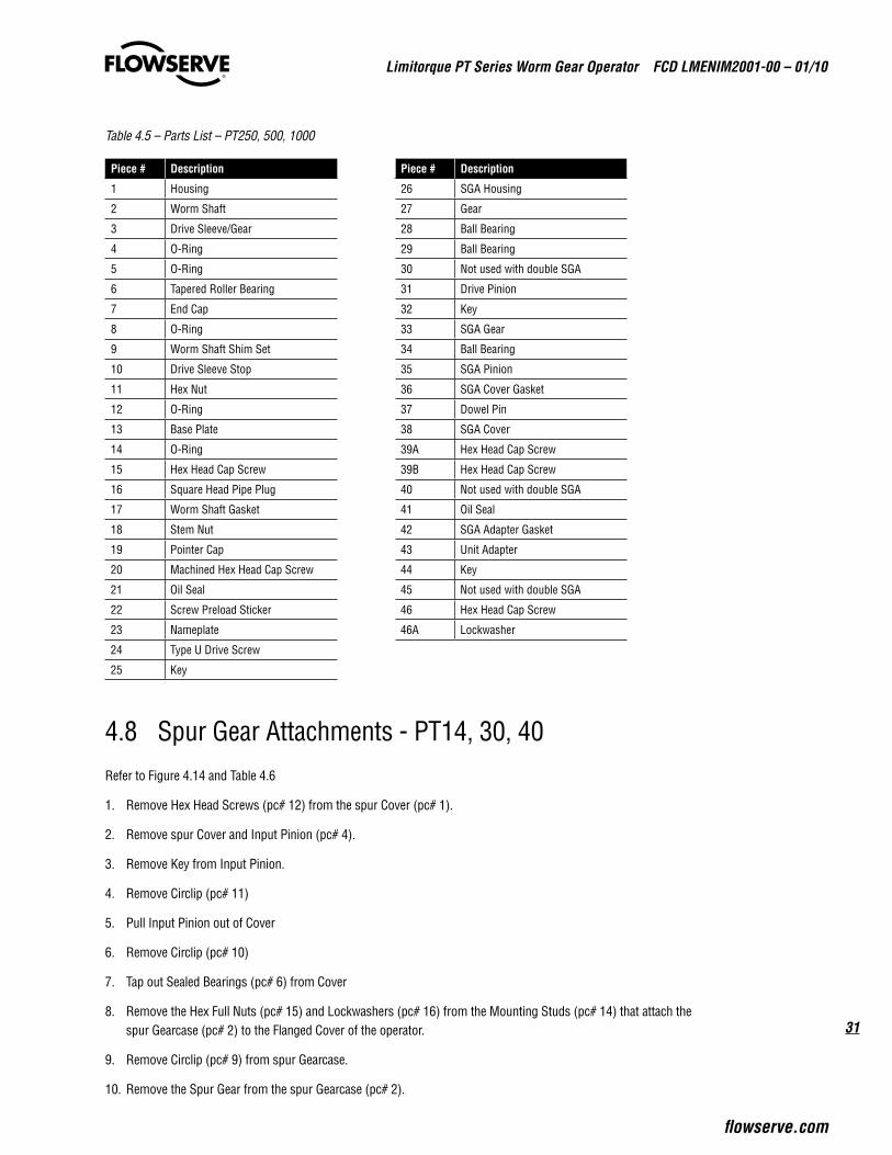
Table 4.5 – Parts List – PT250, 500, 1000
Piece # Description Piece # Description
1 Housing 26 SGA Housing
2 Worm Shaft 27 Gear
3 Drive Sleeve/Gear 28 Ball Bearing
4 O-Ring 29 Ball Bearing
5 O-Ring 30 Not used with double SGA
6 Tapered Roller Bearing 31 Drive Pinion
7 End Cap 32 Key
8 O-Ring 33 SGA Gear
9 Worm Shaft Shim Set 34 Ball Bearing
10 Drive Sleeve Stop 35 SGA Pinion
11 Hex Nut 36 SGA Cover Gasket
12 O-Ring 37 Dowel Pin
13 Base Plate 38 SGA Cover
14 O-Ring 39A Hex Head Cap Screw
15 Hex Head Cap Screw 39B Hex Head Cap Screw
16 Square Head Pipe Plug 40 Not used with double SGA
17 Worm Shaft Gasket 41 Oil Seal
18 Stem Nut 42 SGA Adapter Gasket
19 Pointer Cap 43 Unit Adapter
20 Machined Hex Head Cap Screw 44 Key
21 Oil Seal 45 Not used with double SGA
22 Screw Preload Sticker 46 Hex Head Cap Screw
23 Nameplate 46A Lockwasher
24 Type U Drive Screw
25 Key
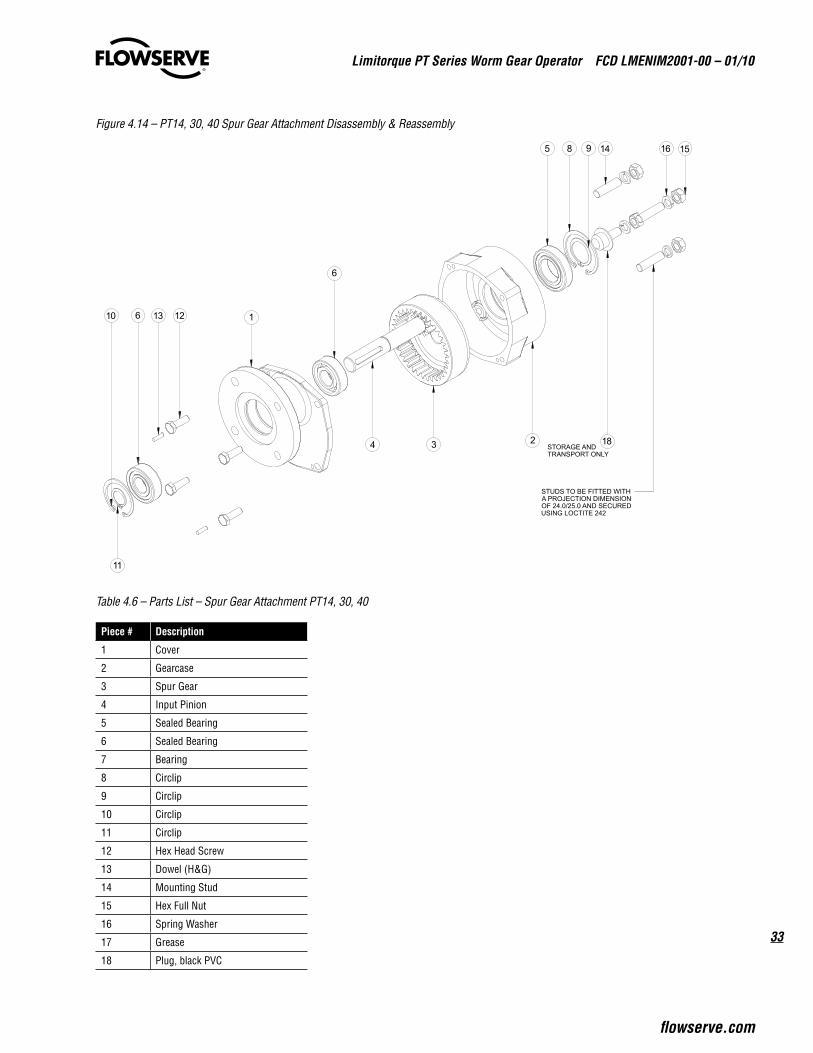
4.8 Spur Gear Attachments - PT14, 30, 40Refer to Figure 4.14 and Table 4.6
1. Remove Hex Head Screws (pc# 12) from the spur Cover (pc# 1).
2. Remove spur Cover and Input Pinion (pc# 4).
3. Remove Key from Input Pinion.
4. Remove Circlip (pc# 11)
5. Pull Input Pinion out of Cover
6. Remove Circlip (pc# 10)
7. Tap out Sealed Bearings (pc# 6) from Cover
8. Remove the Hex Full Nuts (pc# 15) and Lockwashers (pc# 16) from the Mounting Studs (pc# 14) that attach the spur Gearcase (pc# 2) to the Flanged Cover of the operator.
9. Remove Circlip (pc# 9) from spur Gearcase.
10. Remove the Spur Gear from the spur Gearcase (pc# 2).
Limitorque PT Series Worm Gear Operator FCD LMENIM2001-00 – 01/10
32
11. Remove Circlip (pc# 8)
12. Tap out Sealed Bearing (pc# 5)
Reassembly Instructions:
1. If the Sealed Bearing (pc# 5) has been removed from the spur Gearcase (pc# 2), reinstall the bearing and Circlip (pc# 8).
2. Insert the Spur Gear (pc# 3) into the spur Gearcase.
3. Mount the spur Gearcase to the Flanged Cover of the operator, using the Hex Full Nuts and Lockwashers, aligning the key slot with the key slot in the operator Worm Shaft.
Caution: The Worm Shaft Key should remain in the Worm Shaft when the Spur Gear and spur Gearcase are removed from the operator. Be sure the Key is in place prior to installing the spur Gearcase and Spur Gear.
4. Reinstall the two Sealed Bearings (pc# 6) if they were removed from the spur Cover (pc# 1) and install the Circlip (pc# 10).
5. Install the Input Pinion (pc# 4) into the spur Cover (pc# 1) and install the Circlip (pc# 11) to retain the Input Pinion in the spur Cover.
6. Re-lubricate the housing to replace lubricant lost during disassembly.
7. Apply a bead of Loctite 574 or equivalent on the machined surface and around the bolt holes of the spur Gearcase, being careful to avoid applying Loctite into the bolt holes.
8. Install the spur Cover (pc# 1) with Input Pinion (pc# 4), meshing the pinion gear with the Spur Gear.
note: Rotate the input pinion slightly if the pinion gear does not properly mesh with the Spur Gear.
9. Secure the Cover with Hex Head Screws.
10. Install the Pinion Shaft Key.
33
Limitorque PT Series Worm Gear Operator FCD LMENIM2001-00 – 01/10
flowserve.com
Figure 4.14 – PT14, 30, 40 Spur Gear Attachment Disassembly & Reassembly
Table 4.6 – Parts List – Spur Gear Attachment PT14, 30, 40
Piece # Description
1 Cover
2 Gearcase
3 Spur Gear
4 Input Pinion
5 Sealed Bearing
6 Sealed Bearing
7 Bearing
8 Circlip
9 Circlip
10 Circlip
11 Circlip
12 Hex Head Screw
13 Dowel (H&G)
14 Mounting Stud
15 Hex Full Nut
16 Spring Washer
17 Grease
18 Plug, black PVC
5 98 1516
4
6
121310
11
18STORAGE ANDTRANSPORT ONLY
6
3
14
2
1
STUDS TO BE FITTED WITHA PROJECTION DIMENSIONOF 24.0/25.0 AND SECUREDUSING LOCTITE 242
Limitorque PT Series Worm Gear Operator FCD LMENIM2001-00 – 01/10
34
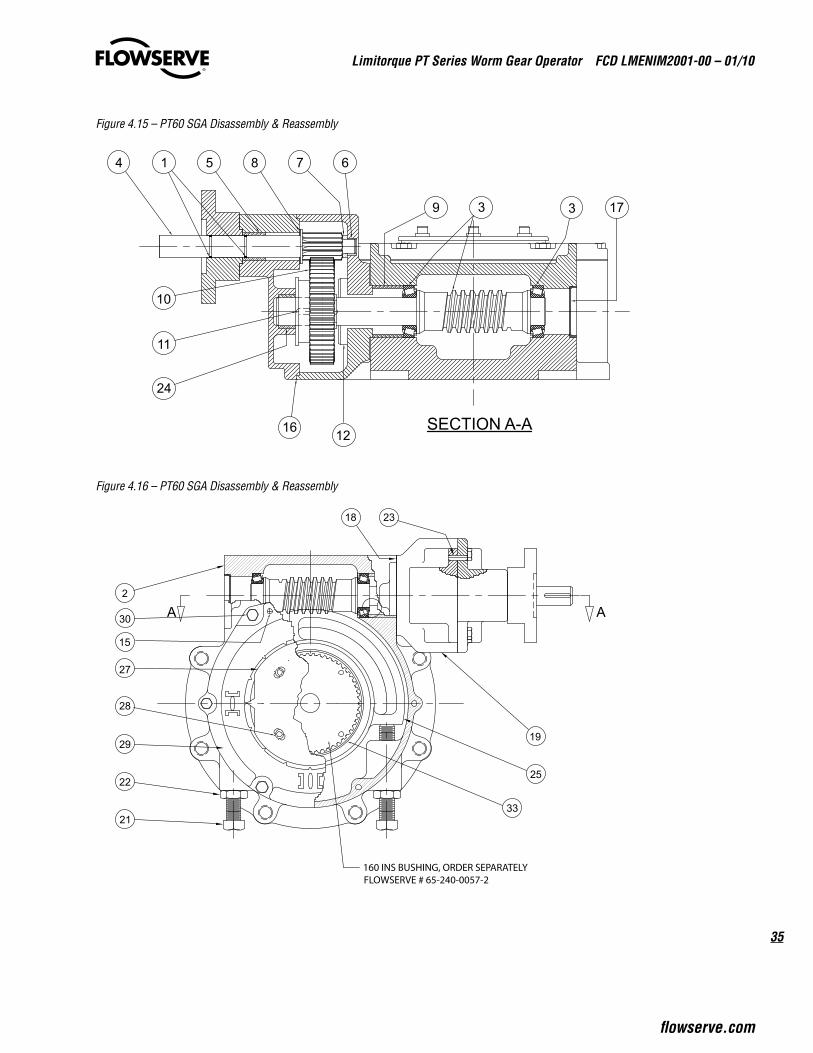
4.9 Spur Gear Attachments - PT60Refer to Figure 4.15, 4.16, 4.17 and Table 4.7
1. Remove the Motor Flange (pc# 14)
2. Remove the Spur Cover (pc# 20) and Spur Cover Seal (pc# 16) from the Spur Housing (pc#19)
note: The cover has a Locating Pin (pc# 23). Use a prying device such as a screwdriver along the edge to free the Spur Housing Cover from the Spur Housing.
3. Remove the Input Shaft (pc# 4) with O-Rings (pc# 1)
4. Remove Spur Gear (pc# 10) and Spur Gear Key (pc# 11)
5. Remove the Spur Housing (pc# 19) and Spur Housing Gaskets (pc# 18)
6. If disassembly of the PT is required, please see section 4.4
Reassembly Instructions:
1. Install all Spur Housing Gaskets (pc# 18) and Spur Housing (pc# 19) with two bolts opposite each other in order to hold the assembly in place against the PT Housing.
Caution: The Spur Housing Gaskets between the Spur Housing and the PT Housing act as shims to set the bearing preload for the tapered roller bearings on the Worm Shaft/Bearing Assembly (pc# 3). The Assembly should have minimum play up and down and end to end. It should also rotate easily.
2. Remove one gasket at a time until the shaft pinches and will not rotate. Add back one gasket to obtain the correct fit.
3. Lightly lubricate the keyed end of the Worm Shaft/Bearing Assembly, (pc# 3) and install the Spur Gear Key (pc# 11)
4. Install the Spur Gear (pc# 10) into the Spur Housing (pc# 19), avoiding pushing it to the bottom of the housing.
5. Lubricate the journal bore for the Input Shaft (pc# 4)
6. Lubricate the Input Shaft and slide it into the journal bore in the Spur Cover (pc# 20). Be sure that the O-Rings (pc# 1) and Input Shaft Washers (pc# 7 & 8) are in place.
7. Ensure that the Spur Cover Locating Pins (pc# 23) in the Spur Cover (pc# 20) are flush with the mating surface of the Spur Cover.
8. Relubricate the Spur Housing (pc# 19) but do not fill completely.
9. Run a bead of silicone sealant around the mating surface of the Spur Housing and Spur Cover.
10. Apply the small end journal washer to the Input Shaft (pc# 4).
11. Install the Spur Cover (pc# 20) with Locating Pins (pc# 23), Spur Cover Gasket (pc# 33), and Input Shaft onto the Spur Housing and aim the small journal of the Input Shaft for the mating bore in the Spur Housing.
12. With the Spur Cover in place and properly seated, drive in the Spur Cover Locating Pins (pc# 23) and install the Cover bolts.
13. Lightly lubricate the bore of the Motor Flange (pc# 14) and bolt the Flange in place.
14. Check the rotation of the Worm Gear through at least one half of the travel of the Gear.
note: Replace any worn or damaged O-Rings or Gaskets to ensure proper sealing.
35
Limitorque PT Series Worm Gear Operator FCD LMENIM2001-00 – 01/10
flowserve.com
Figure 4.15 – PT60 SGA Disassembly & Reassembly
Figure 4.16 – PT60 SGA Disassembly & Reassembly
14
173
SECTION A-A1216
24
11
39
6
10
785
A
21
22
28
29
27
30
2
18 23
A
25
19
33
15
160 INS BUSHING, ORDER SEPARATELYFLOWSERVE # 65-240-0057-2
Limitorque PT Series Worm Gear Operator FCD LMENIM2001-00 – 01/10
36
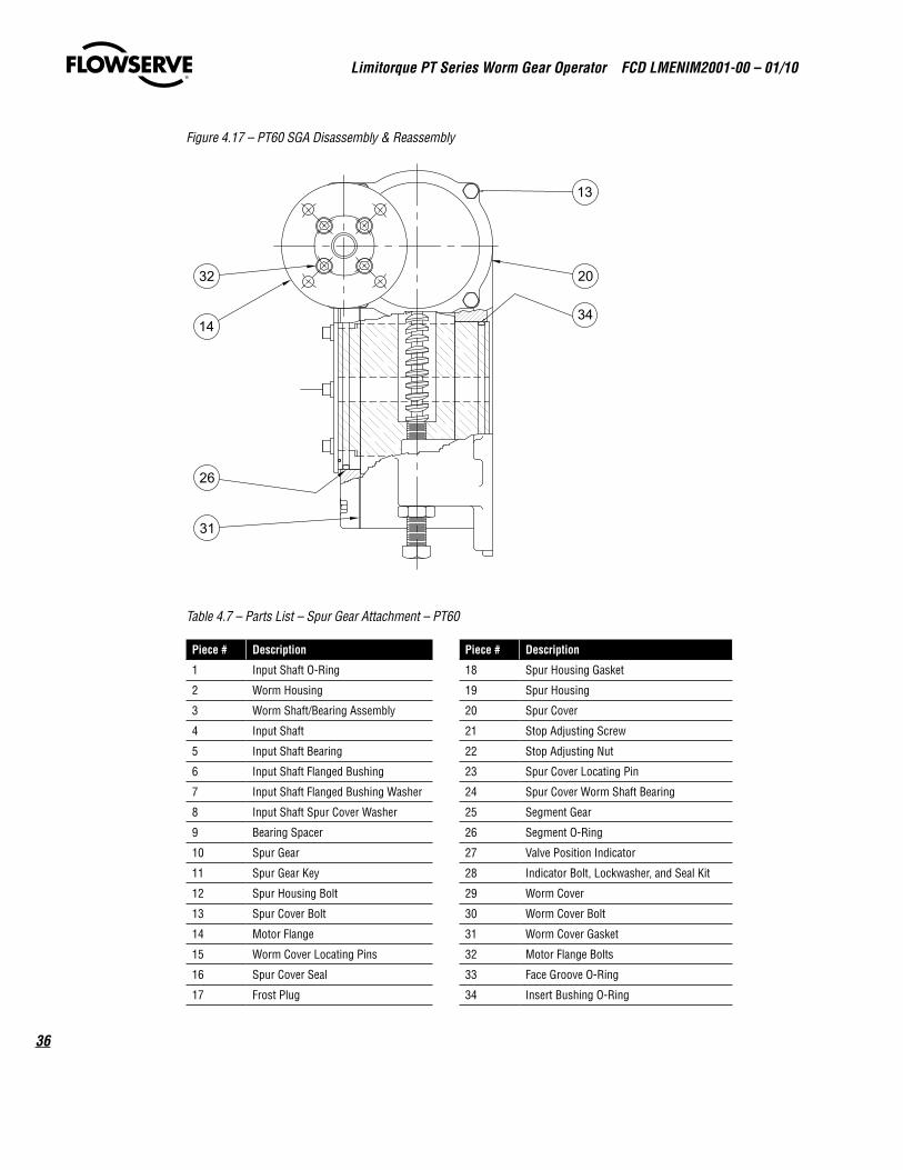
Figure 4.17 – PT60 SGA Disassembly & Reassembly
Table 4.7 – Parts List – Spur Gear Attachment – PT60
Piece # Description Piece # Description
1 Input Shaft O-Ring 18 Spur Housing Gasket
2 Worm Housing 19 Spur Housing
3 Worm Shaft/Bearing Assembly 20 Spur Cover
4 Input Shaft 21 Stop Adjusting Screw
5 Input Shaft Bearing 22 Stop Adjusting Nut
6 Input Shaft Flanged Bushing 23 Spur Cover Locating Pin
7 Input Shaft Flanged Bushing Washer 24 Spur Cover Worm Shaft Bearing
8 Input Shaft Spur Cover Washer 25 Segment Gear
9 Bearing Spacer 26 Segment O-Ring
10 Spur Gear 27 Valve Position Indicator
11 Spur Gear Key 28 Indicator Bolt, Lockwasher, and Seal Kit
12 Spur Housing Bolt 29 Worm Cover
13 Spur Cover Bolt 30 Worm Cover Bolt
14 Motor Flange 31 Worm Cover Gasket
15 Worm Cover Locating Pins 32 Motor Flange Bolts
16 Spur Cover Seal 33 Face Groove O-Ring
17 Frost Plug 34 Insert Bushing O-Ring
31
26
14
32
13
20
34
37
Limitorque PT Series Worm Gear Operator FCD LMENIM2001-00 – 01/10
flowserve.com
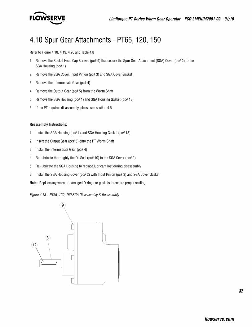
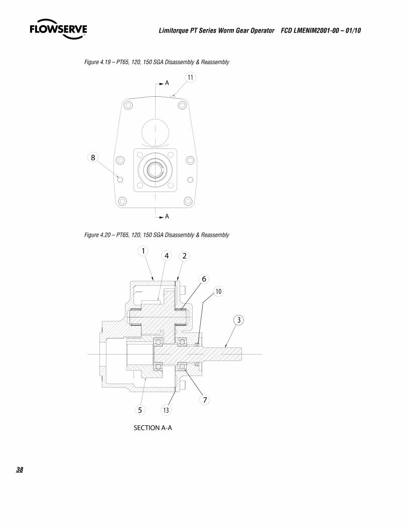
4.10 Spur Gear Attachments - PT65, 120, 150Refer to Figure 4.18, 4.19, 4.20 and Table 4.8
1. Remove the Socket Head Cap Screws (pc# 9) that secure the Spur Gear Attachment (SGA) Cover (pc# 2) to the SGA Housing (pc# 1)
2. Remove the SGA Cover, Input Pinion (pc# 3) and SGA Cover Gasket
3. Remove the Intermediate Gear (pc# 4)
4. Remove the Output Gear (pc# 5) from the Worm Shaft
5. Remove the SGA Housing (pc# 1) and SGA Housing Gasket (pc# 13)
6. If the PT requires disassembly, please see section 4.5
Reassembly Instructions:
1. Install the SGA Housing (pc# 1) and SGA Housing Gasket (pc# 13)
2. Insert the Output Gear (pc# 5) onto the PT Worm Shaft
3. Install the Intermediate Gear (pc# 4)
4. Re-lubricate thoroughly the Oil Seal (pc# 10) in the SGA Cover (pc# 2)
5. Re-lubricate the SGA Housing to replace lubricant lost during disassembly
6. Install the SGA Housing Cover (pc# 2) with Input Pinion (pc# 3) and SGA Cover Gasket.
note: Replace any worn or damaged O-rings or gaskets to ensure proper sealing.
Figure 4.18 – PT65, 120, 150 SGA Disassembly & Reassembly
9
12
3
Limitorque PT Series Worm Gear Operator FCD LMENIM2001-00 – 01/10
38
Figure 4.19 – PT65, 120, 150 SGA Disassembly & Reassembly
Figure 4.20 – PT65, 120, 150 SGA Disassembly & Reassembly
A
A
8
11
SECTION A-A
21 4
6
75
10
13
3
39
Limitorque PT Series Worm Gear Operator FCD LMENIM2001-00 – 01/10
flowserve.com
Table 4.8 – Parts List – Spur Gear Attachment – PT65, 120, 150
Piece # Description
1 SGA Housing
2 SGA Cover
3 Input Pinion
4 Intermediate Gears
5 Output Gear
6 Needle Roller Bearing
7 Radial Ball Bearing
8 Dowel Pin
9 Socket Head Cap Screw
10 Lip Seal
11 Pipe Plug
12 Key
13 SGA Housing Gasket
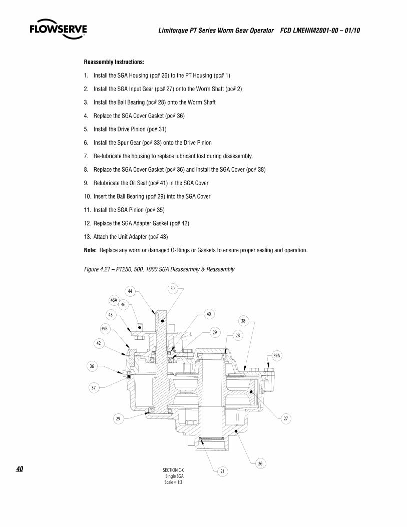
4.11 Spur Gear Attachments - PT250, 500, 1000Refer to Figure 4.21, 4.22 and Table 4.9
1. Remove the hex head cap screws from the Unit Adapter (pc# 43) and remove the Unit Adapter from the SGA (Spur Gear Attachment) Cover (pc# 38).
2. Remove all traces of the SGA Adapter Gasket (pc# 42).
3. Remove the SGA Pinion (pc# 35)
4. Remove the Ball Bearing (pc# 29) from the SGA Cover.
5. Remove the hex head cap screws that attach the SGA Cover to the SGA Housing (pc# 26) and remove the SGA Cover.
6. Remove the Spur Gear (pc# 33) from the Drive Pinion (pc# 31)
7. Remove the Drive Pinion
8. Remove the SGA Cover Gasket (pc# 36) from the SGA Cover surface
9. Remove the Ball Bearing (pc# 28) from the Worm Shaft (pc# 2)
10. Remove the SGA Input Gear (pc# 27) from the Worm Shaft
11. Remove the SGA Housing (pc# 26) from the PT Housing (pc#1)
12. If disassembly of the PT is required, please see section 4.6
Limitorque PT Series Worm Gear Operator FCD LMENIM2001-00 – 01/10
40
Reassembly Instructions:
1. Install the SGA Housing (pc# 26) to the PT Housing (pc# 1)
2. Install the SGA Input Gear (pc# 27) onto the Worm Shaft (pc# 2)
3. Install the Ball Bearing (pc# 28) onto the Worm Shaft
4. Replace the SGA Cover Gasket (pc# 36)
5. Install the Drive Pinion (pc# 31)
6. Install the Spur Gear (pc# 33) onto the Drive Pinion
7. Re-lubricate the housing to replace lubricant lost during disassembly.
8. Replace the SGA Cover Gasket (pc# 36) and install the SGA Cover (pc# 38)
9. Relubricate the Oil Seal (pc# 41) in the SGA Cover
10. Insert the Ball Bearing (pc# 29) into the SGA Cover
11. Install the SGA Pinion (pc# 35)
12. Replace the SGA Adapter Gasket (pc# 42)
13. Attach the Unit Adapter (pc# 43)
note: Replace any worn or damaged O-Rings or Gaskets to ensure proper sealing and operation.
Figure 4.21 – PT250, 500, 1000 SGA Disassembly & Reassembly
43
46
44
SECTION C-CSingle SGA
Scale = 1:3
38
29
37
42
30
40
2829
36
39B
26
27
39A
21
46A
41
Limitorque PT Series Worm Gear Operator FCD LMENIM2001-00 – 01/10
flowserve.com
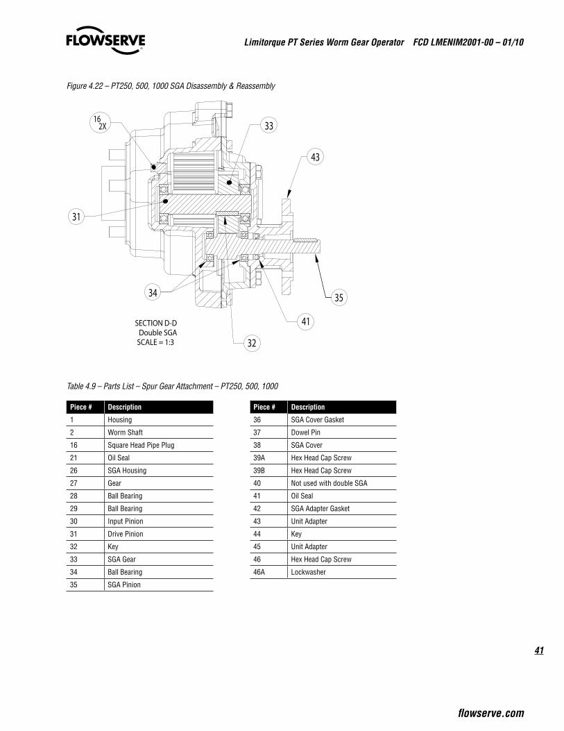
Figure 4.22 – PT250, 500, 1000 SGA Disassembly & Reassembly
SECTION D-D
SCALE = 1:3
41
35
31
32
34
43
162X 33
Double SGA
Table 4.9 – Parts List – Spur Gear Attachment – PT250, 500, 1000
Piece # Description Piece # Description
1 Housing 36 SGA Cover Gasket
2 Worm Shaft 37 Dowel Pin
16 Square Head Pipe Plug 38 SGA Cover
21 Oil Seal 39A Hex Head Cap Screw
26 SGA Housing 39B Hex Head Cap Screw
27 Gear 40 Not used with double SGA
28 Ball Bearing 41 Oil Seal
29 Ball Bearing 42 SGA Adapter Gasket
30 Input Pinion 43 Unit Adapter
31 Drive Pinion 44 Key
32 Key 45 Unit Adapter
33 SGA Gear 46 Hex Head Cap Screw
34 Ball Bearing 46A Lockwasher
35 SGA Pinion

Limitorque PT Series Worm Gear Operator FCD LMENIM2001-00 – 01/10
42
5 How to Order Parts
To order parts or obtain further information about your Limitorque PT valve operator, contact your local Limitorque distributor sales office, www.limitorque.com, or:
Flowserve Limitorque 5114 Woodall RoadLynchburg, VA 24502Telephone: 434-528-4400Fax 434-845-9736
All inquiries or orders must be accompanied by the following information, which is located on the nameplate:
1. Operator size2. Order number3. Serial number

43
Limitorque PT Series Worm Gear Operator FCD LMENIM2001-00 – 01/10
flowserve.com
This page intentionally left blank.
flowserve.com
Flowserve Corporation has established industry leadership in the design and manufacture of its products. When properly selected, this Flowserve product is designed to perform its intended function safely during its useful life. However, the purchaser or user of Flowserve products should be aware that Flowserve products might be used in numerous applications under a wide variety of industrial service conditions. Although Flowserve can (and often does) provide general guidelines, it cannot provide specific data and warnings for all possible applications. The purchaser/user must therefore assume the ultimate responsibility for the proper sizing and selection, installation, operation, and maintenance of Flowserve products. The purchaser/user should read and understand the Installation Operation Maintenance (IOM) instructions included with the product, and train its employees and contractors in the safe use of Flowserve products in connection with the specific application.
While the information and specifications contained in this literature are believed to be accurate, they are supplied for informative purposes only and should not be considered certified or as a guarantee of satisfactory results by reliance thereon. Nothing contained herein is to be construed as a warranty or guarantee, express or implied, regarding any matter with respect to this product. Because Flowserve is continually improving and upgrading its product design, the specifications, dimensions and information contained herein are subject to change without notice. Should any question arise concerning these provisions, the purchaser/user should contact Flowserve Corporation at any one of its worldwide operations or offices.
© 2010 Flowserve Corporation, Irving, Texas, USA. Flowserve is a registered trademark of Flowserve Corporation.
Flowserve CorporationFlow Control
United StatesFlowserve Limitorque5114 Woodall Road, P.O. Box 11318Lynchburg, VA 24506-1318Phone: 434-528-4400Facsimile: 434-845-9736
EnglandFlowserve LimitorqueEuro HouseAbex RoadNewburyBerkshire, RG14 5EYUnited KingdomPhone: 44-1-635-46999Facsimile: 44-1-635-36034
JapanLimitorque – Nippon Gear Co., Ltd.Asahi-Seimei Bldg. 4th Floor1-11-11 Kita-Saiwai, Nishi-KuYokohama-Shi, (220-0004)JapanPhone: 81-45-326-2065Facsimile: 81-45-320-5962
CanadaFlowserve Limitorque120 Vinyl CourtWoodbridge, Ontario L4L 4A3CanadaPhone 905-856-4565Fax 905-856-7905
SingaporeLimitorque Asia, Pte., Ltd.12, Tuas Avenue 20Singapore 638824Phone: 65-6868-4628Facsimile: 65-6862-4940
ChinaLimitorque Beijing, Pte., Ltd.RM A1/A222/F, East Area, Hanwei PlazaNo. 7 Guanghua Road, Chaoyang DistrictBeijing 100004, Peoples Republic of ChinaPhone: 86-10-5921-0606Facsimile: 86-10-6561-2702
IndiaFlowserve LimitorqueNo.10-12, THE OVAL, Third floorVenkatnarayana RoadT. Nagar, Chennai 600 017Phone: 91-44-2432-8755& 91-44-2432-4801Facsimile: 91-44-2432-8754
To find your local Flowserve representative, visit www.flowserve.com, www.limitorque.com or call USA 1 800 225 6989
FCD LMENIM2001-00 Printed in USA. 01/10