user manual - acteon · 2018-05-17 · fpd flat panel detector. 2-dimensional digital detector to...
TRANSCRIPT

CMJN : 15/0/0/85 Pantone 432C RAL 7024 (Graphite grey)
CMJN : 80/0/10/0 Pantone 306C RAL 220 80 25
USER MANUAL
USER MANUAL• X-Mind trium • (13) • 03/2018 • NTR0EN010M

2 USER MANUAL• X-Mind trium • (13) • 03/2018 • NTR0EN010M
ENGLISH
MANUFACTURER
de Götzen® S.r.l. - a company of ACTEON Group
Via Roma, 4521057 OLGIATE OLONA (VA) – ITALY
Tel. +39 0331 376760Fax +39 0331 376763
www.acteongroup.com
FOR INFORMATION AND TECHNICAL ASSISTANCE, CONTACT YOUR LOCAL ACTEON
AUSTRALIA NEW ZEALAND
AUTHORIZED SPONSORACTEON AUTRALIA/NEW [email protected]
CANADA REGULATORY CORRISPONDENTACTEON [email protected]
CHINA ACTEON [email protected]
FRANCE SOPRO - ACTEON [email protected]
GERMANY ACTEON [email protected]
INDIA ACTEON [email protected]
ITALY ACTEON [email protected]
JAPAN MHA Market Authorization HolderHakusui Trading Co., Ltd.
MIDDLE EAST ACTEON MIDDLE [email protected]
RUSSIA ACTEON [email protected]
SPAIN ACTEON MEDICO-DENTAL IBERICA [email protected]
SOUTH AMERICA ACTEON LATIN [email protected]
TAIWAN ACTEON [email protected]
THAILAND ACTEON [email protected]
U.K. ACTEON [email protected]
USA INITIAL IMPORTER / US AGENTACTEON [email protected]
OR THE MANUFACTURER [email protected]

3
ENGLISH
USER MANUAL• X-Mind trium • (13) • 03/2018 • NTR0EN010M
Language of the original document: ENGLISH
Important: All new editions and revisions of the manuals supersede the previous ones
Refer to complete manuals and instructions
For complete manuals and instructions
www.acteongroup.com
Scan the QR code to access the dedicated website
www.acteongroup.com

4 USER MANUAL• X-Mind trium • (13) • 03/2018 • NTR0EN010M
ENGLISH
CONTENTSINTRODUCTION -----------------------------------------------------------------------------------------------6
1.1 CAUTIONS ----------------------------------------------------------------------------------------------------------------------------------- 61.3 IDENTIFICATION TAGS ---------------------------------------------------------------------------------------------------------------- 81.4 POSITION OF THE IDENTIFICATION LABELS -------------------------------------------------------------------------------111.5 STANDARDIZED SYMBOLS ------------------------------------------------------------------------------------------------ 12
DESCRIPTION -------------------------------------------------------------------------------------------------132.1 OPERATOR’S WORKSTATION ------------------------------------------------------------------------------------------------------132.2 X-MIND TRIUM REMOTE CONTROL ---------------------------------------------------------------------------------------------132.3 X-MIND TRIUM MEDICAL DEVICE ------------------------------------------------------------------------------------------------142.4 X-MIND TRIUM CONFIGURATIONS ---------------------------------------------------------------------------------------------162.5 EXAMS ---------------------------------------------------------------------------------------------------------------------------------------162.6 CONTROL PANELS ---------------------------------------------------------------------------------------------------------------------182.7 KEYS DESCRIPTION ---------------------------------------------------------------------------------------------------------------------192.8 LIGHT INDICATORS --------------------------------------------------------------------------------------------------------------------202.9 X-MIND TRIUM REMOTE CONTROL ---------------------------------------------------------------------------------------------202.10 EMERGENCY SWITCHES -------------------------------------------------------------------------------------------------------------212.11 X-RAY EXPOSURE SWITCH ---------------------------------------------------------------------------------------------------------222.12 HEAD SUPPORT FOR PAN/CBCT EXAMS -------------------------------------------------------------------------------------222.13 HEAD SUPPORT FOR CEPH EXAMS ---------------------------------------------------------------------------------------------222.14 ACCESSORIES ---------------------------------------------------------------------------------------------------------------------------23
SWITCHING ON / OFF THE SYSTEM -----------------------------------------------------------------253.1 SWITCHING ON --------------------------------------------------------------------------------------------------------------------------253.2 SWITCHING OFF -------------------------------------------------------------------------------------------------------------------------26
PRE ACQUISITION ------------------------------------------------------------------------------------------274.1 PREPARING THE SYSTEM -------------------------------------------------------------------------------------------------------------274.2 CREATING OR SELECTING PATIENT DATA -------------------------------------------------------------------------------------274.3 INSTRUCTING THE PATIENT -------------------------------------------------------------------------------------------------------274.4 POSITIONING THE PATIENT FOR PAN/CBCT EXAMS ---------------------------------------------------------------------28
PAN ACQUISITION -----------------------------------------------------------------------------------------305.1 SELECTING THE EXAM TYPE --------------------------------------------------------------------------------------------------------305.2 PATIENT POSITIONING ---------------------------------------------------------------------------------------------------------------315.3 EXECUTION OF THE PAN EXAM ---------------------------------------------------------------------------------------------------33
CBCT ACQUISITION ----------------------------------------------------------------------------------------346.1 SELECTING THE EXAM TYPE --------------------------------------------------------------------------------------------------------346.2 PATIENT POSITIONING ---------------------------------------------------------------------------------------------------------------376.3 EXECUTION OF THE CBCT EXAM --------------------------------------------------------------------------------------------------38
CEPH ACQUISITION ----------------------------------------------------------------------------------------407.1 SELECTING THE EXAM TYPE --------------------------------------------------------------------------------------------------------407.2 PATIENT POSITIONING ---------------------------------------------------------------------------------------------------------------407.3 EXECUTION OF THE CEPH EXAM --------------------------------------------------------------------------------------------------42

5
ENGLISH
USER MANUAL• X-Mind trium • (13) • 03/2018 • NTR0EN010M
RELEASING THE PATIENT --------------------------------------------------------------------------------43
MAINTENANCE, CLEANING AND DISPOSAL -----------------------------------------------------449.1 MAINTENANCE --------------------------------------------------------------------------------------------------------------------------449.2 CLEANING ----------------------------------------------------------------------------------------------------------------------------------449.3 DISPOSAL-----------------------------------------------------------------------------------------------------------------------------------44
TROUBLESHOOTING --------------------------------------------------------------------------------------4510.1 ERROR CODES AND REQUIRED ACTIONS------------------------------------------------------------------------------------4510.2 TRIUM ERRORS -------------------------------------------------------------------------------------------------------------------------46
ANNEXES -------------------------------------------------------------------------------------------------------5511.1 DEVICE POWER SUPPLY -------------------------------------------------------------------------------------------------------------5511.2 ELECTRICAL CLASSIFICATION (IEC 60601-1) -------------------------------------------------------------------------------5511.3 X-RAY ASSEMBLY AND X-RAY TUBE --------------------------------------------------------------------------------------------5511.4 DEGREE OF PROTECTION PROVIDED BY ENCLOSURES ---------------------------------------------------------------5711.5 DEVICE MECHANICAL DATA ------------------------------------------------------------------------------------------------------5811.6 WORKSTATION FEATURES ---------------------------------------------------------------------------------------------------------5811.7 DETECTORS ------------------------------------------------------------------------------------------------------------------------------5811.8 SCANNING PARAMETERS – PAN/CEPH ---------------------------------------------------------------------------------------5911.9 SCANNING PARAMETERS – CBCT -----------------------------------------------------------------------------------------------5911.10 LASER ------------------------------------------------------------------------------------------------------------------------------------6011.11 FIRMWARE DATA --------------------------------------------------------------------------------------------------------------------6011.12 CLIENT PC MINIMUM REQUIREMENTS ------------------------------------------------------------------------------------6011.13 INTENDED ENVIRONMENT ------------------------------------------------------------------------------------------------------6111.14 DIMENSIONS OF THE UNIT -----------------------------------------------------------------------------------------------------6111.15 LIST OF INTERNATIONAL STANDARDS AND DIRECTIVES ----------------------------------------------------------6311.16 DOSIMETRIC INDICATIONS -----------------------------------------------------------------------------------------------------6311.16.2 DOSIMETRIC INDICATIONS IN TERMS OF CTDI (FOR CBCT EXAMS) ------------------------------------------------------------- 7411.17 ELECTROMAGNETIC COMPATIBILITY ---------------------------------------------------------------------------------------8211.17.1 RECOMMENDED SEPARATION DISTANCES ------------------------------------------------------------------------------------------------ 8211.17.2 ELECTROMAGNETIC EMISSIONS -------------------------------------------------------------------------------------------------------------- 8211.17.3 ELECTROMAGNETIC IMMUNITY --------------------------------------------------------------------------------------------------------------- 8311.17.4 ELECTROMAGNETIC IMMUNITY, HANDHELD RADIOFREQUENCY EQUIPMENT --------------------------------------------- 84
WARNINGS ----------------------------------------------------------------------------------------------------85
INTERACTIONS CONTRAINDICATIONS PROHIBITIONS ------------------------------------88

1
6 USER MANUAL• X-Mind trium • (13) • 03/2018 • NTR0EN010M
ENGLISH
INTRODUCTIONThank you for choosing the X-MIND trium. The electro medical equipment described in this manual refers to the X-Mind trium medical device.
X-MIND trium is a radiological device and must be used and handled only by specialised surgeons, dentists and authorised and duly trained personnel, who meet the requirements provided by the national laws in force in the country of installation. The training and preparation of personnel must be included in the tasks of the responsible organization.
Before using the X-MIND trium, the operator must read and understand all the instructions provided in the manual in order to obtain the highest performance and ensure the safety of patients, of operators, of the medical device and the environment.
X-MIND trium is a digital panoramic, cephalometric and tomographic extra-oral X-ray system, indicated for use in:- producing panoramic X-ray images for diagnostic examination of dentition (teeth), jaws and oral structures;- producing radiographs of maxillofacial region and parts of the skull for cephalometric examination, if equipped with CEPH arm;- producing radiographs of hands and wrists for carpus examination, if equipped with CEPH arm;- producing tomographic images of the oral and maxillofacial region, for diagnostic examination of dentition (teeth), jaws, oral structures and some cranial bones, if equipped with CBCT option.
This medical device complies with the essential requirements of European Directive 93/42/EEC. This equipment is designed and developed in compliance with Electrical Safety standard IEC 60601-1 in force. It was designed and manufactured in accordance with an EN ISO 13485-certified quality assurance system and Good Manufacturing Practices (21 CFR 820).
From a clinical point of view, the X-MIND trium can be applied for the following medical applications:• Generic dentistry• Dental implantology• Dental surgery• Maxillo-facial surgery• Cephalometric analysis• Carpus radiology
The target patient population includes adults and pediatric patients from 5 years old [~21 kg (46 lb); 113 cm (44.5 in) standing height]; anyway the sustainability to X-ray exposure must be evaluated by surgeons, dentists and qualified and authorized physicians.The intended user profile is a qualified, trained and authorized physician or dentist who meets the requirements provided by national laws in force in the country of installation; the operator must understand the language of the country where the device is installed.
Contraindications: Viewing cartilaginous structures; The CBCT technique has a limited capability of detecting soft tissues.
1.1 CAUTIONS
CAUTION :CAUTION messages refer to circumstances that can jeopardise the operator’s safety, cause injuries to operators and patients or damage the medical device and the environment.
! WARNING :WARNING messages refer to circumstances that can compromise the performance of the X-MIND trium medical device.
NOTE :

7
ENGLISH
USER MANUAL• X-Mind trium • (13) • 03/2018 • NTR0EN010M
NOTE messages provide indications for easier maintenance and highlight important information.
1.1 MANUFACTURER RESPONSIBILITY
The manufacturer shall under no circumstances be held liable for injuries to persons or damage to property caused by:• Non-compliance with manufacturer recommendations during installation, whether this is the network voltage or the electromagnetic environment,• Maintenance or repair procedures performed by people who are unauthorized by the manufacturer,• Use on an electrical fixture that is not compliant with regulations in force,• Uses other than those specified in this manual.• Use of accessories (temple rest, chin rest, bites, etc.) other than those supplied by ACTEON Imaging,• Use of hygienic protections different from class I Medical Device Directive 93/42/EEC and subsequent amendments or not compliant with ISO 10993 series of standards.• Non-compliance with the instructions contained in the accompanying documents.Note: the manufacturer reserves the right to modify the medical device and/or any documentation without notice.
1.2 WARRANTY
Any improper use or unauthorised modification to the medical device shall relieve the manufacturer of the medical device, from the obligation to provide assistance covered by warranty and from any liability. This will also result in additional charges for technical assistance not covered by warranty.
The warranty is valid only if the following requirements are complied with:• Repairs, modifications, adjustments and calibrations must be carried out solely by ACTEON Group or by qualified, authorised and/or trained personnel.• Installation must be carried out by qualified and trained technicians in compliance with the standards in force and as recommend by the manufacturer.• This medical device must be installed and used following the instructions provided in the installation manual and in the attached documents. • The mains power supply must provide the required power and its characteristics must meet the specifications indicated on the medical device identification label.• The medical device must be periodically inspected by qualified, authorized and trained technical personnel in compliance with the standards in force and with the manuals provided by the manufacturer.

8 USER MANUAL• X-Mind trium • (13) • 03/2018 • NTR0EN010M
ENGLISH
Terminology used in the manual:
TERM MEANING
AOR Axis Of Rotation. Axis of rotation of the U-Arm.
CBCT Medical device that acquires radiological images, using a cone radiation beam and reconstructs the 3D volume of the scan.
CEPH Is the common name for Cephalometry or Cephalostat.
DGI Proprietary file format used to save digital radiological projections.
DICOM Digital Imaging and Communications in Medicine. Medical imaging standard that defines the rules and criteria to transfer, view, store and print information in medical imaging, in order to ensure communication between medical devices and information systems.
FOV Field Of View. The volume scanned and reconstructed by the X-MIND trium medical device.
FPD Flat Panel Detector. 2-dimensional digital detector to acquire radiographic projections.
PAN Is the common name for panoramic image or Orthopantomogram.
ROI Region of Interest. Patient’s anatomical area to be examined and segmented in a tomographic image.
HU Hounsfield Unit. Standard reference scale used to describe radiodensity in systems.
AIS Acteon imaging Suite software that manages all the functional aspects of the X-MIND trium system, including: patient database, patient acquisition, calibrations, quality tests, maintenance, display that allows the operator to make the diagnosis and treatment planning.
1.3 IDENTIFICATION TAGS
X-MIND TRIUM LABEL
X-RAY ASSEMBLY label

9
ENGLISH
USER MANUAL• X-Mind trium • (13) • 03/2018 • NTR0EN010M
X-RAY BEAM LIMITER label
CAUTION X-RAYS LABEL
CAUTION LASER BEAM LABEL FRANKFURT LASER APERTURE
Please see section 11.11 for more details
X-MIND trium is a class 3R laser product. Avoid direct eye exposure to laser radiation. Viewing the laser output with telescopic optical instruments (for example, telescopes and binoculars) may pose an eye hazard and thus the user should not direct the beam into an area where such instruments are likely to be used
Use of controls or adjustments or performance of procedures other than those specified herein may result in hazardous radiation exposure
PAN DETECTOR LABEL

10 USER MANUAL• X-Mind trium • (13) • 03/2018 • NTR0EN010M
ENGLISH
REMOVABLE DETECTOR LABEL
3D DETECTOR LABEL
CEPH ARM LABEL
ETL MARKING
UDI LABEL
11
ENGLISH
USER MANUAL• X-Mind trium • (13) • 03/2018 • NTR0EN010M
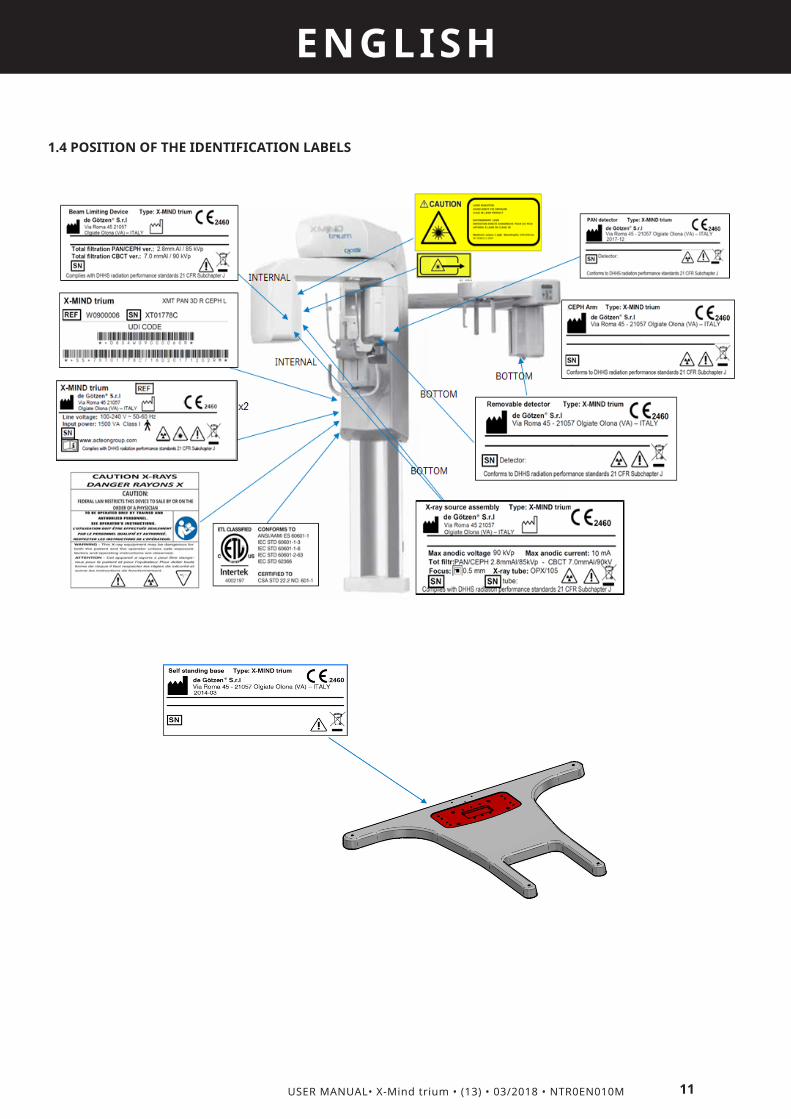
1.4 POSITION OF THE IDENTIFICATION LABELS

12 USER MANUAL• X-Mind trium • (13) • 03/2018 • NTR0EN010M
ENGLISH
1.5 STANDARDIZED SYMBOLS
En: Power ON (IEC 60417)
En: Power OFF (IEC 60417)
En: Protective earth (IEC 60417)
En: Alternating current (IEC 60417)
En: Applied Part: Type B (IEC 60601-1)
Attention, refer to the attached documents
Ionising radiation hazard
Emitting X-ray equipment (IEC 60417)
Laser beam hazard (ISO 3864)
Laser beam aperture
Do not dispose of a household waste
Size of the focal spot (small)
Hazardous Voltage
Emergency Stop Command
Electrostatic discharge sensitive device
Pause
X-ray command
xxxx
This symbol guarantees that the x-ray system complies with the regulations contained in the European directive 93/42/EEC and subsequent amendments regarding medical devices.
This symbol reminds that is mandatory to carefully read the whole documentation and manuals provided with the medical device before to perform whatever operation.
Electronic instructions for use symbol for medical devices, according to EN ISO 15223-1: 2016

2
13
ENGLISH
USER MANUAL• X-Mind trium • (13) • 03/2018 • NTR0EN010M
DESCRIPTION
The X-MIND trium medical device system consists of:
2.1 OPERATOR’S WORKSTATION
The operator’s workstation is provided optionally for the PAN only unit.
The workstation allows the operator to perform the following procedures:• Calibrations of the medical device• Acquisition parameters setting• Radiological image acquisition • Image visualization and post processing• Database management • Periodic quality TestsThe workstation must have installed the following modules: • ACTEON IMAGING SUITE (AIS) equipment management software + 2D diagnostic analysis• AIS 3D app (CBCT)Communication with the medical device occurs by means of Ethernet protocol.
2.2 X-MIND TRIUM REMOTE CONTROL
The X-MIND trium remote control must be located in a safe place protected against radiations, in compliance with the local standards in force concerning ionising radiation protection.The X-MIND trium remote control allows the operator to activate or deactivate X-ray emission from the control room. This consists of two switches, one for exposure and one for emergency, which control device operation.

14 USER MANUAL• X-Mind trium • (13) • 03/2018 • NTR0EN010M
ENGLISH
X-MIND trium Light
The X-MIND trium Light is an indicator light that warns that X-ray emission is in progress.It indicates no entry into the room when the red light is on; it also has a triangular danger sign that warns of X-ray hazards.
2.3 X-MIND TRIUM MEDICAL DEVICE
The X-MIND trium medical device for PAN/CBCT models consists of the following parts:1. Control panel. The control panel provides an intuitive overview of the system to move the mobile column, move the bite
block holder (only PAN/CBCT version), move the U-arm, turn the positioning lasers on and off and activate the X-MIND trium medical device.
2. X-ray generator. The X-ray assembly is the source of the X-ray beam during the rotation of the U-Arm. An automatic collimator shapes the X-Ray beam, whereas the electronic control ensures stability and accuracy of the selected loading factors (exposure time, kVp and anodic current). A filter is used to harden the beam and remove low-energy ionising radiations, thereby obtaining suitable radiation quality whilst reducing its dose absorbed by the patient. The filter’s material is aluminium for PAN and CEPH exams, aluminium + copper for CBCT exams.
3. Sliding body. The sliding body is the mobile part of the column that supports U-arm.4. U-arm. The U-Arm supports the PAN/CBCT Detector sliding group and the X-ray generator. This is the rotating part of
the medical device, which moves around the patient during the image acquisition phase ; it can as well be moved in two horizontal directions (X and Y) by the operator during the setup of the exam, in order to obtain the best superimposition between the patient’s head anatomy and the diameter of the Field of View (FOV).
5. Detector sliding group. It contains detectors that allow to acquire PAN and CBCT images.6. CBCT detector. This flat panel detector is indicated for use in generating radiographic images of the maxillo-facial region,
more specifically it is dedicated for CBCT acquisitions.

15
ENGLISH
USER MANUAL• X-Mind trium • (13) • 03/2018 • NTR0EN010M
7. PAN detector. This flat panel detector is indicated for use in generating radiographic images of the maxillo-facial region, more specifically it is dedicated for PAN acquisitions.
8. Patient support. The patient support allows stabilising and immobilising the patient. It can be moved vertically in order to obtain the best superimposition between the patient’s head anatomy and the height of Field of View (FOV).
9. F group. It is the whole assembled mobile group of the device. It is the moving part of the medical device, which adapts the acquisition geometry to the patient’s anatomy and stance (sitting or standing). It supports the U-Arm and head support
10. Column. The fixed column supports the entire structure of the medical device. This contains the motor that raises the F Group.
Overview of the medical device: Cephalometric extension:
The Cephalometric version of X-MIND trium medical device consists of the parts listed above and of the following additional parts:11. CEPH arm extension. Can be positioned both on the right or left side of the vertical column.12. CEPH control panel. Provides an intuitive overview of the system to move the mobile column and activate the X-MIND trium medical device.13. CEPH patient support. Allows stabilising and immobilising the patient during CEPH exams, by means of ears rest and nasion rest.14. CEPH detector sliding group. Enables to slide the detector to follow the X-Ray beam.15. CEPH secondary collimator. Is positioned on U-arm; it translates during X-Rays (keeping aligned the X-Ray beam emerging from the tube head with the CEPH detector).16. CEPH detector. This flat panel detector is indicated for use in generating radiographic images of the maxillo-facial region, more specifically it is dedicated for CEPH acquisitions. It gives 2D images of the whole patient head; this detector can optionally be moved from the CEPH arm to the detector sliding group for PAN examinations.
16 USER MANUAL• X-Mind trium • (13) • 03/2018 • NTR0EN010M
ENGLISH
2.4 X-MIND TRIUM CONFIGURATIONS
X-MIND trium can be sold in these configurations:PAN only • The equipment can carry out uniquely exams of the PAN group (PAN, TMJ, Sinus);• The image detector is fixed to the PAN bay;• All the exams are carried out with the same extension in height (146 mm height on image receptor), primary collimator being of fixed dimension;• The equipment can be upgraded in a later stage by replacing and adding several parts.
PAN and CBCT • The equipment can carry out both exams of the PAN group (PAN, TMJ, Sinus) and of the CBCT group;• There are two image detectors, one for PAN and one for CBCT exam; the equipment automatically exposes in front of X-Ray source the right detector, depending on the selected exam;• PAN exams can be carried out with different extension in height (up to 146 mm height on image receptor), since the collimator height can be adjusted depending on the exam selected by the user;• CBCT exams can be carried out at different FOV dimensions as specified in the technical data appendix;• The equipment can be upgraded in the field to CEPH configuration by simple procedure, adding CEPH arm with CEPH image detector replacing the existing PAN image detector.
PAN / CEPH • The equipment can carry out both exams of the PAN group (PAN, TMJ, Sinus) and of the CEPH group (AP/PA, LL, carpus);• The image detector can optionally be unique, both for PAN and CEPH exams, and in this case it must be manually moved by the operator from PAN bay to CEPH bay and viceversa, depending on the selected exam; otherwise two different detectors can be dedicated: one for CEPH exams and the other one for PAN exams;• The exams can be carried out with different extension in height (up to 146 mm height on image receptor for PAN, up to 220 mm height on image receptor for CEPH), since the primary collimator can be automatically adjusted in height depending on exam selected by the user;• The equipment can be upgraded in the field to CBCT configuration by a simple procedure, adding CBCT image detector and bite block holder with vertical movement.
PAN / CBCT / CEPH • The equipment can carry out all feasible exams of the PAN group (PAN, TMJ, Sinus), of the CEPH group (AP/PA, LL, carpus) and of the CBCT group;• There are optionally two image detectors, one for PAN/CEPH and one for CBCT exam; in this case the PAN/CEPH image detector must be manually moved by the operator from PAN bay to CEPH bay and viceversa; otherwise three image detectors, one for PAN, one for CEPH and one for CBCT exams;• To carry out PAN or CEPH or CBCT exam the equipment automatically exposes in front of X-Ray source the right detector, depending on the selected exam;• PAN and CEPH exams can be carried out with different extension in height (up to 146 mm height on image receptor for PAN, up to 220 mm height on image receptor for CEPH), since the primary collimator can be automatically adjusted in height depending on exam selected by the user;• CBCT exams can be carried out at different FOV dimensions as specified in the technical data appendix.
2.5 EXAMS
In its different configurations X-MIND trium equipment carries out the following exams:
Panoramic groupThe panoramic group includes all the 2D radiographs of the jaws, dentition, temporomandibular joints and maxillary sinuses.
1) Standard panoramic· Full scan· Right side only· Left side only

17
ENGLISH
USER MANUAL• X-Mind trium • (13) • 03/2018 • NTR0EN010M
2) Sectorial panoramic with improved orthogonality· Full scan· Right side only· Left side only
3) Frontal panoramic
4) Bitewings
5) Frontal temporomandibular joint with closed or open mouth· Both sides· Left TMJ only· Right TMJ only
6) Lateral temporomandibular joint with closed or open mouth· Both sides· Left TMJ only· Right TMJ only
7) Frontal maxillary sinuses
8) Lateral maxillary sinuses· Left sinus only· Right sinus only
CBCT groupThe CBCT group includes all the 3D CBCT examinations of the dental and maxillofacial regions.Here below the size of the reconstructed volumes expressed as diameter x height.
1) Dental FOV· 40mm x 40mm· 60mm x 60mm· 80mm x 80mm· 110mm x 80mm
NOTE :A specific version of AIS software disables FOV 110mm X 80mm
2) ENT FOV – Nose· 110mm x 80mm
NOTE :A specific version of AIS software disables FOV 110mm X 80mm
3) ENT FOV – Ear· Left ear only, 60mm x 60mm· Right ear only, 60mm x 60mm
Cephalometric group• Frontal (AP/PA)• Lateral (LL)• Hand acquisition (Carpus - special support needed)
For all examination groups, the operator set the predefined loading factors, in terms of X-ray anodic current and X-ray tube voltage, by selecting the patient type between the following options:
· MAN- small

18 USER MANUAL• X-Mind trium • (13) • 03/2018 • NTR0EN010M
ENGLISH
- medium- large
· WOMAN- small- medium- large
· CHILD- small- medium- large
For the panoramic group and the cephalometric group, the operator can still modify the loading factors by means of dedicated sliders.
! WARNING :Only physicians or dentists properly trained can modify the loading factors from the predefined values for the panoramic and cephalometric groups taking into account the effects on the image quality, increase/decrease of radiation dose and the needs of the clinical task.
On the contrary, for the CBCT group, the operator cannot modify the anodic current and tube voltage, but can just select the quality of the 3D reconstruction between three protocols:· Standard quality· Medium quality· High qualityThe X-ray exposure time of the scan increases from the standard quality to the high quality involving both the improvement of the image quality and the increase of the radiation dose to the patient.
! WARNING :Only physicians or dentists properly trained can select the quality protocol for the CBCT groups taking into account the effects on the image quality, increase / decrease of radiation dose and the needs of the clinical task.
2.6 CONTROL PANELS
Equipment control panels are used during patient positioning phase.Available keys allow to move the equipment to Initial position before patient access, turn on positioning LASERs, adjust the U-arm position to align the patient to X-ray beam and set the “ready to X-ray” status.Some keys are duplicated on the CEPH control panel, for use during patient positioning for CEPH exams.
Equipment control panel CEPH control panel
19
ENGLISH
USER MANUAL• X-Mind trium • (13) • 03/2018 • NTR0EN010M
CAUTION :Some of the keys give the operator the possibility to move parts of the equipment. When pressing them the operator must check carefully the patient and, in case of possible collision between equipment and patient, stop immediately the movement by releasing the key.
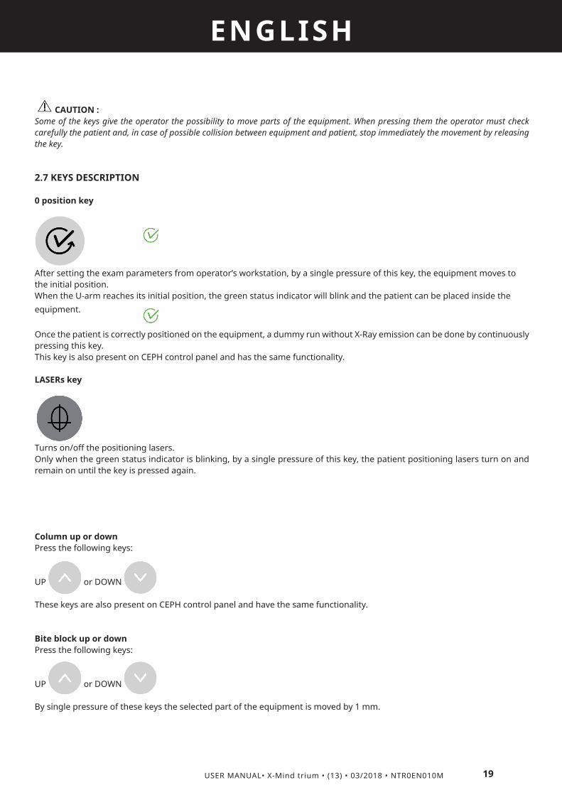
2.7 KEYS DESCRIPTION
0 position key
After setting the exam parameters from operator’s workstation, by a single pressure of this key, the equipment moves to the initial position.When the U-arm reaches its initial position, the green status indicator will blink and the patient can be placed inside the equipment. Once the patient is correctly positioned on the equipment, a dummy run without X-Ray emission can be done by continuously pressing this key.This key is also present on CEPH control panel and has the same functionality.
LASERs key
Turns on/off the positioning lasers.Only when the green status indicator is blinking, by a single pressure of this key, the patient positioning lasers turn on and remain on until the key is pressed again.
Column up or downPress the following keys:
UP or DOWN
These keys are also present on CEPH control panel and have the same functionality.
Bite block up or downPress the following keys:
UP or DOWN
By single pressure of these keys the selected part of the equipment is moved by 1 mm.

20 USER MANUAL• X-Mind trium • (13) • 03/2018 • NTR0EN010M
ENGLISH
Horizontal movements keys
These keys move the U arm in the arrows direction, in order to place the LASER in the required position on patient face.By single pressure of one of these keys the rotating U-arm is moved by 1 mm in the arrow direction.These keys are enabled only for a sub-set of exams; for all remaining exams the pressure on these keys does not have any effect.
2.8 LIGHT INDICATORS
Green Status indicator
• Blinking. The equipment is in the initial position. Patient can be placed under the equipment and positioning LASERs can be turned ON.• ON. The acquisition can start.This indicator is also present on CEPH control panel.
Yellow X-Ray indicator
• OFF. No X-Ray emission.• ON. X-Ray emission on going.
Red Error indicator
• ON. The equipment is in error status.
2.9 X-MIND TRIUM REMOTE CONTROL
The X-MIND trium remote control must be kept in a safe place protected against radiations, in compliance with local standards in force concerning radiation protection. The X-MIND trium remote control allows the operator to activate or deactivate X-ray emissions from the control room.
The components are listed below with a brief description of the parts.
1. Safety key selector switch. Deactivates the X-ray emission switch to prevent accidental exposure.

21
ENGLISH
USER MANUAL• X-Mind trium • (13) • 03/2018 • NTR0EN010M
2. X-ray emission LED. Remains on during the entire acquisition.3. Remote emergency switch. Allows stopping the device in the event of emergency.4. X-ray emission switch. Activates acquisition.
2.10 EMERGENCY SWITCHES
This device is equipped with two emergency switches that allow to stop the movement of parts and X-ray emission in the event of an emergency.
Patient emergency switch
The patient emergency switch is installed on the head support and is within the patient’s reach, to allow both the patient and the operator to stop the device in the event of panic or hazards, sudden column motion or any anomaly. The operator must inform and instruct the patient on the emergency procedures and on the use of the emergency switches of the device, as indicated in this chapter.
Remote emergency switch
1= Remote emergency switch
The Remote emergency switch is located on the X-MIND trium remote control.
How to use the emergency switchesIn case of an emergency, stop any movement of the device and X-ray emission by pressing either the patient emergency switch or the remote emergency switch. This action puts the device in the emergency status.To reset the emergency status, first solve the emergency condition and then release the emergency switch by turning it clockwise until it reaches its initial position.

22 USER MANUAL• X-Mind trium • (13) • 03/2018 • NTR0EN010M
ENGLISH
2.11 X-RAY EXPOSURE SWITCH
To activate the exposure, the operator must press and hold the X-ray exposure switch for the entire acquisition. Meanwhile, the yellow X-ray exposure LED stays ON to indicate X-ray emission. If the operator removes his/her finger from the exposure button before acquisition is complete, X-ray emission and U-Arm rotation will be interrupted and the X-ray exposure LED will turn off. At this point, an error message appears in the AIS software. This message must be deleted before using the medical device again.
2.12 HEAD SUPPORT FOR PAN/CBCT EXAMS
The head support positions and immobilises the patient before the scan. It is equipped with a chin rest and forehead support to ensure maximum stability.
1. Temple rest2. Patient mirror3. Patient emergency switch4. Courtesy tray5. Handlebar6. Temple knob7. Chin rest8. Bite block
2.13 HEAD SUPPORT FOR CEPH EXAMSThe head support in CEPH arm positions and immobilises the patient before the scan. It is equipped with a couple of ear rests and a nose support to ensure maximum stability.
23
ENGLISH
USER MANUAL• X-Mind trium • (13) • 03/2018 • NTR0EN010M
1. Ear rest2. Ear rest knob 3. Nose support
To adapt to the patient’s anatomy, the CEPH head support is equipped with:• Ear rest knob for horizontal ear rest movement.• Nose support, that can be manually moved in horizontal and in vertical.
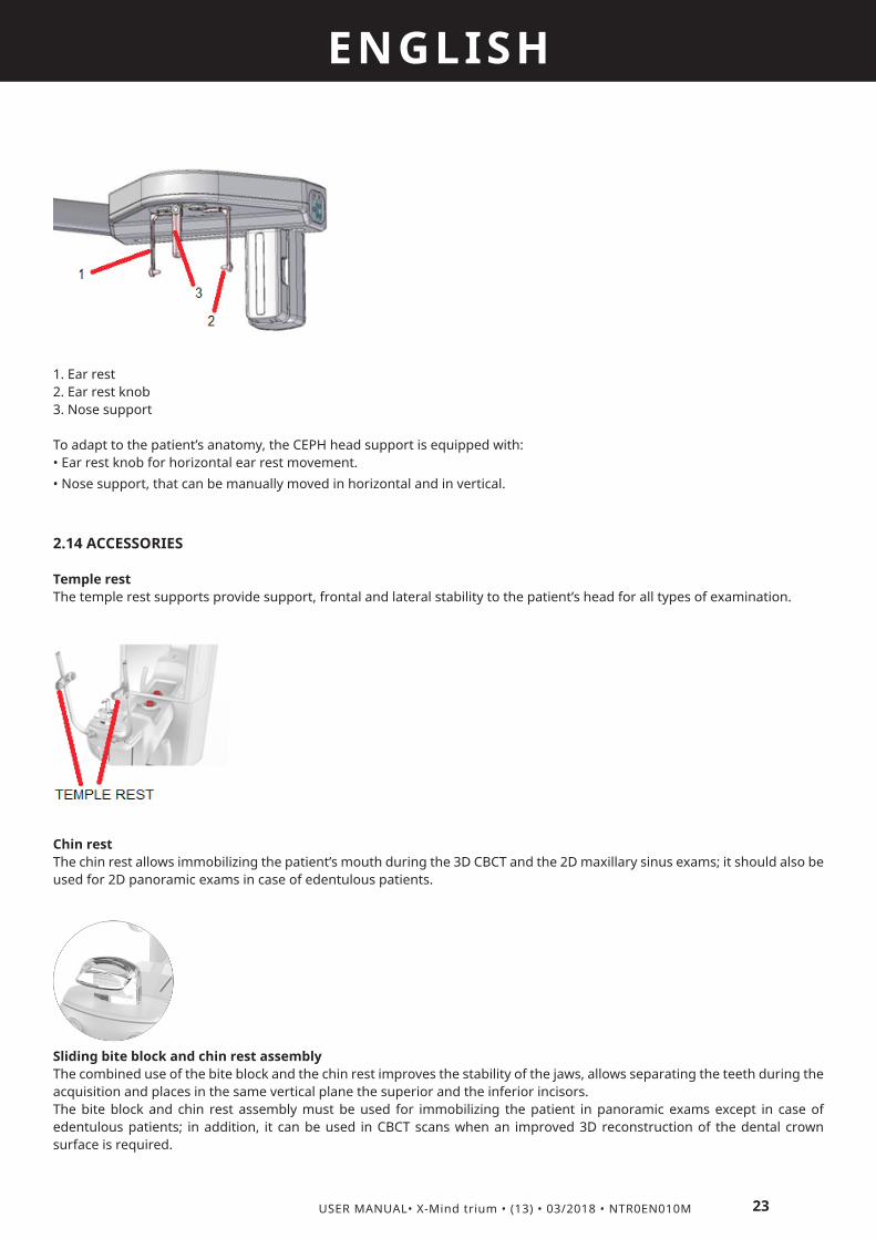
2.14 ACCESSORIES
Temple restThe temple rest supports provide support, frontal and lateral stability to the patient’s head for all types of examination.
Chin rest The chin rest allows immobilizing the patient’s mouth during the 3D CBCT and the 2D maxillary sinus exams; it should also be used for 2D panoramic exams in case of edentulous patients.
Sliding bite block and chin rest assemblyThe combined use of the bite block and the chin rest improves the stability of the jaws, allows separating the teeth during the acquisition and places in the same vertical plane the superior and the inferior incisors.The bite block and chin rest assembly must be used for immobilizing the patient in panoramic exams except in case of edentulous patients; in addition, it can be used in CBCT scans when an improved 3D reconstruction of the dental crown surface is required.
24 USER MANUAL• X-Mind trium • (13) • 03/2018 • NTR0EN010M
ENGLISH
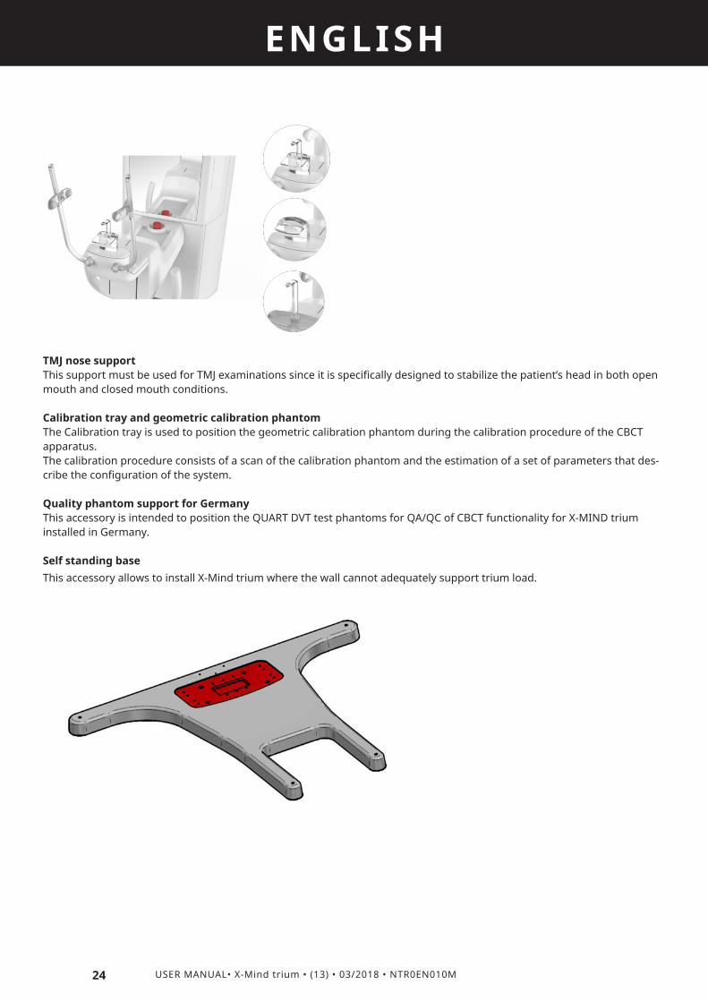
TMJ nose supportThis support must be used for TMJ examinations since it is specifically designed to stabilize the patient’s head in both open mouth and closed mouth conditions.
Calibration tray and geometric calibration phantomThe Calibration tray is used to position the geometric calibration phantom during the calibration procedure of the CBCT apparatus.The calibration procedure consists of a scan of the calibration phantom and the estimation of a set of parameters that des-cribe the configuration of the system.
Quality phantom support for GermanyThis accessory is intended to position the QUART DVT test phantoms for QA/QC of CBCT functionality for X-MIND trium installed in Germany.
Self standing baseThis accessory allows to install X-Mind trium where the wall cannot adequately support trium load.

3
25
ENGLISH
USER MANUAL• X-Mind trium • (13) • 03/2018 • NTR0EN010M
SWITCHING ON / OFF THE SYSTEM 3.1 SWITCHING ON
To turn the system ON, proceed as follows:
• Ensure that the system is properly connected to the power supply. • Switch the medical device by setting the Main switch to ON position (I). The main switch is located below the patient support.
1 Main switch
• Switch on the workstation.• Log into the operating system and click on the icon of the AIS software. • Wait for the AIS to be launched.• Select the language among the available ones, type in the User Name and Password and press OK.• X-MIND trium automatically loads the software and connects the workstation with the medical device.• Check connection status between device and workstation referring to the icon shown on the display of the control panel

26 USER MANUAL• X-Mind trium • (13) • 03/2018 • NTR0EN010M
ENGLISH
Not connected
• This icon is shown during device start-up, when workstation is turned off or if there is a connection problem.
Connected
• The medical device is ready to perform acquisitions, calibrations and quality tests.
3.2 SWITCHING OFF
• To turn the system off, proceed as follows:
• Press the EXIT button in the MENU BAR of the AIS software.• Turn the X-MIND trium workstation off. • Switch OFF the medical device by setting the main switch to off. The main switch is located on the lower part of the patient support.
CAUTION :Always switch the system off during long period of inactivity like night time, weekends and holidays.

4
27
ENGLISH
USER MANUAL• X-Mind trium • (13) • 03/2018 • NTR0EN010M
PRE ACQUISITIONThis chapter describes the procedure to acquire images of a new patient using X-MIND trium.The instructions below describe how to prepare the system, position the patient and scan the anatomical volume.
4.1 PREPARING THE SYSTEM
• Upon starting the system, wait at least 5 minutes before carrying out an acquisition, calibration or quality test. Failure to comply with this provision can cause noise and defects in the acquired images. • Ensure that all components are operating and that there are no error messages or notifications. • Ensure that the medical device is properly calibrated.
4.2 CREATING OR SELECTING PATIENT DATA
Patient data must be created or selected from patient database. To do so, follow the procedure described in the manual of Acteon imaging suite software.
- Select the exam
4.3 INSTRUCTING THE PATIENT
• Describe the functions of the device to the patient, position the patient, and provide all the safety instructions.• Use the demo function to show the patient how the U-Arm rotates (PAN/CBCT exams) or detector translates (CEPH image) during the scan. • To start this function, press and keep pressed the “0 Position” key on the control panel.
CAUTION :Never position the patient or have the patient inside the machine during the «0 position» phase!
• To stop the demo movement, release “0 Position” key. Press the button again to bring the U-Arm back to its initial position. • Explain in detail the use of the local emergency switch. • Ask the patient to remove any metal object or jewel from his / her head, neck or mouth (earrings, necklaces, partial dentures, hairclips).• Pay special attention in the cases of children, disabled people, seniors and obese persons. • Instruct patients on how to control their breathing during the scan. Breathing should be slow and low to minimise patient movements. • Complete all the preliminary steps before positioning the patient to minimise the time to perform the examination and prevent delays.

28 USER MANUAL• X-Mind trium • (13) • 03/2018 • NTR0EN010M
ENGLISH
4.4 POSITIONING THE PATIENT FOR PAN/CBCT EXAMS
This section describes the procedure to place the patient on the device and to carry out all panoramic and CBCT scan.
• Install the patient support best suited to the examination to be carried out, as described in the table here below:
Support Examination Specific note
Temple rest • All exams
Chin rest • All exams of the CBCT group• Frontal and lateral maxillary sinuses• Standard panoramic, orthogonal panoramic, bitewings and frontal
panoramic, only in case of edentulous patients
Suitable for edentulous patients
Sliding bite block and chin rest assembly
• All exams of CBCT group, if 3D reconstruction of crowns of teeth is required• Standard panoramic, orthogonal panoramic, bitewings and frontal
panoramic
Unsuitable for edentulous patients
TMJ nose support
• Frontal and lateral TMJ with open or close mouth Suitable for edentulous patients
• Apply the disposable protection devices (class I Medical Device Directive 93/42/EEC and subsequent amendments) to the parts that come into contact with the patient: chin rest, temple rest, bite block and handlebar.
CAUTION :The bite covers can cause dangerous injuries (even death) if swallowed.Please use the disposable protections as recommended by the manufacturers in the instructions for use; make sure the disposable protections are fixed on their support and cannot move in the mouth or in the throat of the patient.
• Use the COLUMN UP and DOWN buttons to adjust the height of the mobile column and adapt the head support to the patient’s stance (sitting or standing).

29
ENGLISH
USER MANUAL• X-Mind trium • (13) • 03/2018 • NTR0EN010M
• Ask the patient to approach the head support and hold of the handlebar. Ask the patient to have a natural posture and relax. • Ask the patient to firmly grasp the handgrip with both hands.• If the patient is fitted with a lead-lined apron for radiation protection, make sure that his neck is not covered, because this will cause unexposed areas in the radiograph.
The X-MIND trium is equipped with five laser beams that help the operator position the patient in the FOV.• Ask the patient to close his/her eyes.• When the patient’s eyes are closed, turn the lasers on by pressing the PATIENT POSITIONING LASER button on the control panel. The positioning lasers will light up.
A = Patient positioning laser button.For details about the use of the lasers, refer to paragraphs 5.2 (for PAN exams) and 6.2 (for CBCT exams).
5
30 USER MANUAL• X-Mind trium • (13) • 03/2018 • NTR0EN010M
ENGLISH
PAN ACQUISITION5.1 SELECTING THE EXAM TYPE
· From the AIS tool bar press the PAN button to enter in the acquisition window.
· From the acquisition window (refer to AIS Operator’s manual for the description of the acquisition window) select the patient’s type (man, woman, child) and size (small, medium, large).
· Select the type of exam and check the predefined loading factors.
· Press the “0 position” button.
· The green status indicator will start blinking and the U-arm will reach the reset position.
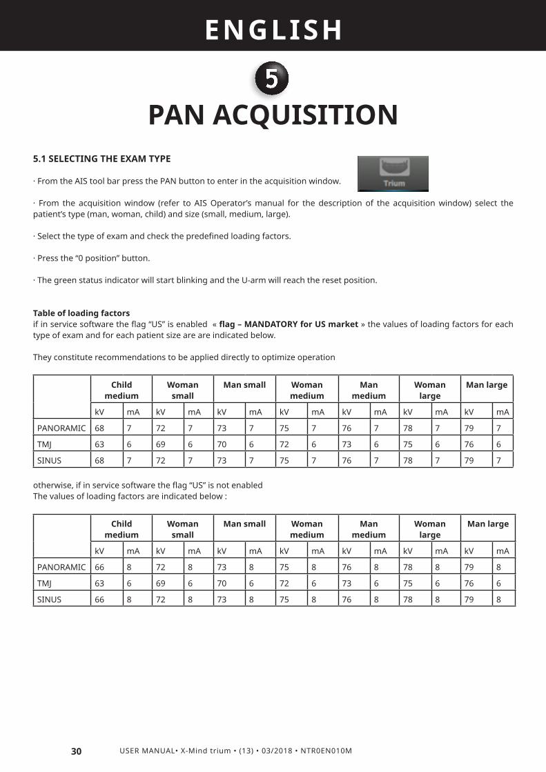
Table of loading factorsif in service software the flag “US” is enabled « flag – MANDATORY for US market » the values of loading factors for each type of exam and for each patient size are are indicated below.
They constitute recommendations to be applied directly to optimize operation
Child medium
Woman small
Man small Woman medium
Man medium
Woman large
Man large
kV mA kV mA kV mA kV mA kV mA kV mA kV mA
PANORAMIC 68 7 72 7 73 7 75 7 76 7 78 7 79 7
TMJ 63 6 69 6 70 6 72 6 73 6 75 6 76 6
SINUS 68 7 72 7 73 7 75 7 76 7 78 7 79 7
otherwise, if in service software the flag “US” is not enabledThe values of loading factors are indicated below :
Child medium
Woman small
Man small Woman medium
Man medium
Woman large
Man large
kV mA kV mA kV mA kV mA kV mA kV mA kV mA
PANORAMIC 66 8 72 8 73 8 75 8 76 8 78 8 79 8
TMJ 63 6 69 6 70 6 72 6 73 6 75 6 76 6
SINUS 66 8 72 8 73 8 75 8 76 8 78 8 79 8
31
ENGLISH
USER MANUAL• X-Mind trium • (13) • 03/2018 • NTR0EN010M
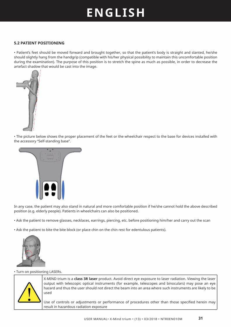
5.2 PATIENT POSITIONING
• Patient’s feet should be moved forward and brought together, so that the patient’s body is straight and slanted, he/she should slightly hang from the handgrip (compatible with his/her physical possibility to maintain this uncomfortable position during the examination). The purpose of this position is to stretch the spine as much as possible, in order to decrease the artefact shadow that would be cast into the image.
• The picture below shows the proper placement of the feet or the wheelchair respect to the base for devices installed with the accessory “Self-standing base”.
In any case, the patient may also stand in natural and more comfortable position if he/she cannot hold the above described position (e.g. elderly people). Patients in wheelchairs can also be positioned.
• Ask the patient to remove glasses, necklaces, earrings, piercing, etc. before positioning him/her and carry out the scan
• Ask the patient to bite the bite block (or place chin on the chin rest for edentulous patients).
• Turn on positioning LASERs.
X-MIND trium is a class 3R laser product. Avoid direct eye exposure to laser radiation. Viewing the laser output with telescopic optical instruments (for example, telescopes and binoculars) may pose an eye hazard and thus the user should not direct the beam into an area where such instruments are likely to be used
Use of controls or adjustments or performance of procedures other than those specified herein may result in hazardous radiation exposure

32 USER MANUAL• X-Mind trium • (13) • 03/2018 • NTR0EN010M
ENGLISH
• Close temple rest on the patient forehead and, gently move patients head to the correct position with his mid-sagittal plane corresponding to the mid-sagittal LASER.
• Move slightly up or down the equipment until Frankfurt laser is centered on Frankfurt plane of the patient. This laser is composed by five lines. Refer to one of these lines to position the patient. Be sure that this line (and consequently patient’s Frankfurt plane) is horizontal and parallel to the floor.
• If it is necessary, adjust the machine in order to centre the canine laser plane on the patient canine for PAN and SINUS exams and on temporo-mandibular jont for TMJ exams. Move the U-arm by pressing the dedicated keys to adjust the anterior or posterior directions.
for PANORAMIC and SINUS exams for TMJ exams

33
ENGLISH
USER MANUAL• X-Mind trium • (13) • 03/2018 • NTR0EN010M
• After that the patient is properly positioned on the chin rest or bite support, adjust the temple rest support by means of the temple rest knobs.
• Ensure that the patient is positioned in such a way that no part of the body can come into contact with or collide against the mobile column or the U-Arm or the CEPH arm during the scan.
• Ensure that hair and clothes do not remain caught in the mobile column or in the U-Arm.
• Ask the patient to keep tongue raised on the palate.
• Ask the patient to keep still during U-arm rotation or any mechanical motion of the device.
5.3 EXECUTION OF THE PAN EXAM
• Once the patient is correctly positioned, press “O position” button; the green status indicator will be ON.• Ask the patient to press his/her tongue to the palate.• Ask the patient to stay still during the whole exposure.• Go out from the room to start exam; do not forget to observe the applicable radiation safety procedure.• Start the PAN exam by pressing the X-ray emission switch on the X-MIND trium remote control. During this stage, the device emits X-rays; the X-ray emission LED on the control panel and the X-ray exposure LED on the X-MIND trium remote control will light up.
A = X-ray emission switchB = X-ray emission LED
• Keep the switch pressed for the whole duration of the exam until the U-arm stops. If the switch is released earlier, the X-ray emission and the carriage movements will be stopped and the exam is irremediably interrupted (“dead man” exposure mode); in this case, the device must be reset and the patient positioning redone.
CAUTION :Monitor the patient throughout the entire exposure. In the event of an emergency, release the Xray exposure switch to stop the U-arm rotation and X-ray emission.In the event that the U-arm rotation and/or X-ray emission do not stop, press the remote emergency switch.
6
34 USER MANUAL• X-Mind trium • (13) • 03/2018 • NTR0EN010M
ENGLISH
CBCT ACQUISITION6.1 SELECTING THE EXAM TYPE · From the AIS tool bar press the CBCT button to enter in the acquisition window.
· From the acquisition window (refer to AIS Operator’s manual for the description of the acquisition window) select the patient type (man, woman, child) and size (small, medium, large).
· Select the sector of the exam (dental, nose, ear), the dimension of the FOV and the quality of the image, then check the predefined loading factors.
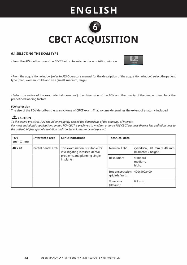
FOV selectionThe size of the FOV describes the scan volume of CBCT exam. That volume determines the extent of anatomy included.
CAUTION To the extent practical, FOV should only slightly exceed the dimensions of the anatomy of interest.For most endodontic applications limited FOV CBCT is preferred to medium or large FOV CBCT because there is less radiation dose to the patient, higher spatial resolution and shorter volumes to be interpreted.
FOV (mm X mm)
Interested area Clinic indications Technical data
40 x 40 Partial dental arch This examination is suitable for investigating localised dental problems and planning single implants.
Nominal FOV: cylindrical, 40 mm x 40 mm (diameter x height)
Resolution: standardmedium, high,
Reconstruction grid (default):
400x400x400
Voxel size (default):
0.1 mm

35
ENGLISH
USER MANUAL• X-Mind trium • (13) • 03/2018 • NTR0EN010M
FOV (mm X mm)
Interested area Clinic indications Technical data
60 x 60 Half dental arch This examination is suitable for investigating localised dental problems and planning single implants.
Nominal FOV: cylindrical, 60 mm x 60 mm (diameter x height)
Resolution: low, medium, high, custom
Ear This examination is useful for diagnostic investigations of the auditory system. Reconstruction
grid (default):600x600x600
Voxel size (default):
0.1 mm
FOV (mm X mm)
Interested area Clinic indications Technical data
80 x 80 Dental arch The dental arch examination allows viewing the entire oral region, including the mental and mandibular foramen.
Nominal FOV: cylindrical, 80 mm x 80 mm (diameter x height)
Resolution: low, medium, high, custom
Reconstruction grid (default):
500x500x500
Voxel size (default):
0.15 mm
FOV (mm X mm)
Interested area Clinic indications Technical data
110 x 80
NOTE :A specific version of AIS software disables FOV 110mm X 80mm
Full dental arch The full dental arch examination shows the entire dental region, mandibular anatomy, lower paranasal sinuses, TMJ and airways. The software uses the volumetric data to reconstruct a virtual dental panoramic view. This digital panoramic projection is of higher quality than conventional ones, thanks to the absence of geometric distortions and reduction of partial volume effects.
Nominal FOV: cylindrical, 110 mm x 80 mm (diameter x height)
Resolution: low, medium, high, custom
Nose This examination is used for diagnostic investigations of upper airways and paranasal sinuses.
Reconstruction grid (default):
693x693x500
Voxel size (default):
0.15 mm

36 USER MANUAL• X-Mind trium • (13) • 03/2018 • NTR0EN010M
ENGLISH
RESOLUTION selection
Set high resolution (High Quality) to improve the diagnostic accuracy of endodontic-specific tasks such as the visualization of small features including calcified/accessory canals, missed canals, disruptions in the periodontal ligament space, small alterations, etc.If the Standard or Medium protocol can be used for a diagnostic task that requires lower resolution, it should be employed, absent strong indications to the contrary.
CAUTION For choice of resolution take also in account the increase of dose of Medium and High quality with respect to Standard: refer to section 11.15.2 for dosimetric indications (CTDI for CBCT EXAMS) · Press the “0 position” button.
-The green status indicator will start blinking and the U-arm will reach the reset position.
Table of loading factors
The values of loading factors indicated below for each patient size are predefined; they constitute recommendations to be applied directly to optimize operation.
Child medium
Woman small Man small Woman medium
Man medium Woman large Man large
kV mA kV mA kV mA kV mA kV mA kV mA kV mA
CBCT 80 8 85 6 90 6 85 8 90 8 85 10 90 10
CAUTION :The TYPE OF EXAM SECTION controls the collimation openings to obtain the required FOV. Bear in mind that a broader FOV is obtained by a wider X-ray beam which encloses a larger anatomical region but also implies an increase in radiation dose absorbed by the patient.

37
ENGLISH
USER MANUAL• X-Mind trium • (13) • 03/2018 • NTR0EN010M
6.2 PATIENT POSITIONING
X-MIND trium is a class 3R laser product. Avoid direct eye exposure to laser radiation. Viewing the laser output with telescopic optical instruments (for example, telescopes and binoculars) may pose an eye hazard and thus the user should not direct the beam into an area where such instruments are likely to be used
Use of controls or adjustments or performance of procedures other than those specified herein may result in hazardous radiation exposure
• The mid-sagittal plane laser (A) is located on the U-arm and identifies the sagittal plane. It is used to position the patient symmetrically with respect to the rotation axis of the scanning apparatus. • The Axial plane laser (B) is located on the X-ray tube and identifies the bottom limit of the X-ray beam, that is the bottom limit of the acquired volume.• The coronal plane laser (C) identifies the coronal plane and is also located on the X-ray tube.
The intersection between the mid-sagittal plane laser and the coronal plane laser represents the Axis of Rotation (AOR) of the scanning apparatus, that is the central axis of the acquired volume.
Once the patient is positioned correctly with respect to the lasers, adjust the chin rest support by means of the control panel commands in order to reach the correct position.

38 USER MANUAL• X-Mind trium • (13) • 03/2018 • NTR0EN010M
ENGLISH
Close temple rest on the patient forehead and gently move the patient’s head to the correct position with his/her mid-sagittal plane corresponding to the mid-sagittal LASER.
6.3 EXECUTION OF THE CBCT EXAM
• Once the patient is correctly positioned, press “O position” key.
• The green status indicator will be ON and the U-arm will reach the start position.
• Ask the patient to stay still during the whole exposure.
• Go out from the room to start exam; do not forget to observe the applicable radiation safety procedure.
• Start the CBCT scan or acquire a scout view of the patient by pressing the X-ray emission switch on the X-MIND trium remote control. During this stage, the device emits X-rays; the X-ray emission LED on the control panel and the X-ray exposure LED on the X-MIND trium remote control will light up.
A = X-ray emission switchB = X-ray emission LED

39
ENGLISH
USER MANUAL• X-Mind trium • (13) • 03/2018 • NTR0EN010M
• In case of CBCT scan, keep the switch pressed for the whole duration of the exam until the U-arm stops. If the switch is released earlier, the X-ray emission and the carriage movements will be stopped and the exam is irremediably interrupted (“dead man” exposure mode); in this case, the device must be reset and the patient positioning redone.• In case the scout view has been selected, evaluate the scout view to establish whether the patient is positioned correctly.• If the patient is positioned correctly, press YES to continue with the acquisition, otherwise, press NO to repeat the patient positioning procedure.
CAUTION :Monitor the patient throughout the entire exposure. In the event of an emergency, release the X-ray exposure switch to stop the U-Arm rotation and X-ray emission.In the event that the U-Arm rotation and/or X-ray emission do not stop, press the remote emergency switch.

7
40 USER MANUAL• X-Mind trium • (13) • 03/2018 • NTR0EN010M
ENGLISH
CEPH ACQUISITION7.1 SELECTING THE EXAM TYPE
· From the AIS tool bar press the CEPH button to enter in the acquisition window.
· From the acquisition window (refer to AIS Operator’s manual for the description of the acquisition window) select the patient type (man, woman, child) and size (small, medium, large).· Select the type of CEPH exam (LL, AP/PA, Carpus) and check the predefined loading factors.· Press the “0 position” button.· The green status indicator will start blinking and the CEPH detector sliding group will reach the reset position.
Table of loading factorsif in service software the flag “US” is enabled « flag – MANDATORY for US market » the values of loading factors for each type of exam and for each patient size are are indicated below.
They constitute recommendations to be applied directly to optimize operation
Child medium
Woman small
Man small Woman medium
Man medium
Woman large
Man large
kV mA kV mA kV mA kV mA kV mA kV mA kV mA
CEPH AP/PA 68 6 72 6 73 6 75 6 76 6 77 6 78 6
CEPH LL 68 8 72 8 73 8 75 8 76 8 77 8 78 8
CARPUS 66 9 72 9 73 9 75 9 76 9 77 9 78 9 otherwise, if in service software the flag “US” is not enabledThe values of loading factors are indicated below :
Child medium
Woman small
Man small Woman medium
Man medium
Woman large
Man large
kV mA kV mA kV mA kV mA kV mA kV mA kV mA
CEPH AP/PA 72 9 76 9 77 9 79 9 80 9 82 9 83 9
CEPH LL 71 8 75 8 76 8 78 8 79 8 81 8 82 8
CARPUS 66 9 72 9 73 9 75 9 76 9 78 9 79 9
7.2 PATIENT POSITIONING
Bring the patient to the equipment, in front of CEPH patient support:• Turn manually the whole head support to one of the three allowed positions, depending on the selected exam: AP, PA, carpus or LL.• Set equipment height until ear rests are at the patient ears’ height. • Open horizontally the ear rests acting on the dedicated rests knobs.• Turn in horizontal position the nose support.• Ask the patient to slowly place himself/herself between the ear rests.• Close the ear rests on the patient ears and gently move the patient’s head to the correct position with his mid-sagittal plane corresponding to the vertical axis. • Turn nose support in vertical position and move it vertically and horizontally until the extreme side of the support is on the nose root;

41
ENGLISH
USER MANUAL• X-Mind trium • (13) • 03/2018 • NTR0EN010M
For CARPUS exam only, follow the next instructions:+ Place the dedicated carpus support (a) on the CEPH patient support, lifting it with the aid of the two pins (p), then fixing it
with the screw (s1).
+ Open horizontally the ear rests to their maximum aperture (b).+ Turn in horizontal position the nose support (c).+ Ask the patient to place its hand on the carpus support, verifying that it is completely included in the rectangular area drawn on the support (a).
Proceed with the execution of the exam.

42 USER MANUAL• X-Mind trium • (13) • 03/2018 • NTR0EN010M
ENGLISH
7.3 EXECUTION OF THE CEPH EXAM
• Once the patient is correctly positioned, press “O position button” exam button.
• The green status indicator will be ON and the U-arm will reach the start position.
• Ask the patient to stay still during the whole exposure.• Go out from the room to start exam; do not forget to observe the applicable radiation safety procedure.• Start the CEPH exam by pressing the X-ray emission switch on the X-MIND trium remote control. During this stage, the device emits X-rays; the X-ray emission LED on the control panel and the X-ray exposure LED on the X-MIND trium remote control will light up.
A = X-ray emission switchB = X-ray emission LED
· Keep the switch pressed for the whole duration of the exam until the CEPH detector sliding group stops. If the switch is released early, the X-ray emission and the carriage movements will be stopped and the exam is irremediably interrupted (“dead man” exposure mode); in this case, the device must be reset and the patient positioningredone.
CAUTION :Monitor the patient throughout the entire exposure. In the event of emergency, release the X-ray exposure switch to stop the CEPH detector sliding group shift and X-ray emission.In the event that the sliding group shifts and/or X-ray emission doesn’t stop, press the remote emergency switch.

8
43
ENGLISH
USER MANUAL• X-Mind trium • (13) • 03/2018 • NTR0EN010M
RELEASING THE PATIENT
• Go inside the radiologic room, open temple rest or the ear rests and ask patient to move carefully from the equipment. • Image will be available on the PC connected to Trium.• After exposure the device will start a cooling down period as indicated on the control panel display.
In case of an error, a code will be shown on the display, and a red light turns on warning the operator about malfunctioning. For error details please refer to the “TROUBLESHOOTING” chapter.

9
44 USER MANUAL• X-Mind trium • (13) • 03/2018 • NTR0EN010M
ENGLISH
MAINTENANCE, CLEANING AND DISPOSAL
9.1 MAINTENANCE
Periodic verification of the emergency switches.To ensure the safety of patients and operators, verify the proper operation of the remote emergency switch and local emergency switch on a monthly basis.To verify the proper operation of remote and local emergency switches, proceed as follows:• Turn the device on and make sure that it is operating correctly.• Click on the U-arm rotation button on the control panel to start a reset to 0 position of the U-arm.
• Whilst the U-Arm is in motion, press the local emergency switch; the U-Arm should immediately stop as a proof of the proper operation of the emergency switch.• Reset the emergency status by turning the local emergency switch clockwise and bringing it back to its initial position.• Repeat the same procedure for the remote emergency switch.
CAUTION :If an emergency switch does not work properly, contact the technical support service.
Calibration and quality controlCalibration and quality tests verify the operation and performance of the device; these tests must be carried out together with the inspection of the safety devices at least once every 6 months, unless otherwise specified in the frequency table of the installation and maintenance manual.For other details of maintenance operations, refer to the installation and maintenance manuals.The manufacturer shall not be held liable for damage or injuries caused by failure to carry out inspections and tests and by incomplete maintenance.Repairs and replacements of any component must be carried out solely by authorized and highly qualified personnel and only using genuine spare parts supplied by de Götzen® S.r.l. - ACTEON Group.
9.2 CLEANING
Clean the external surface using a damp cloth with non-corrosive and non oil-based detergent; disinfect the external surface using a non-aggressive medical detergent. Do not spray any detergent or disinfectant directly on the device.
9.3 DISPOSAL
The WEEE symbol indicates that, at the end of its lifespan, the product must be disposed of separately from other waste, in compliance with Directive WEEE 2012/19 EU.Refer to the implementation standards in your country. EU Council Directive WEEE 2012/19 EU defines a common approach intended to avoid, prevent or reduce harmful effects due to the exposure to environmental noise and to the disposal of electric and electronic equipment. This product is marked with the symbol shown above. This product must not be disposed of together with domestic waste. It must be taken to a special waste collection centre to be recovered and recycled. The crossed-out wheelie bin identifies a product placed on the market after the 13th of August 2005 (see EN 50419:2006). This product is subjected to Council Directive WEEE 2012/19 EU and national implementation standards. Refer to your supplier for the disposal of this product.Proper disposal of this product will help protect the environment.For further details on the disposal of this product, please contact local authorities, the provider of the domestic waste disposal service or the dealer where you have purchased it.
10
45
ENGLISH
USER MANUAL• X-Mind trium • (13) • 03/2018 • NTR0EN010M
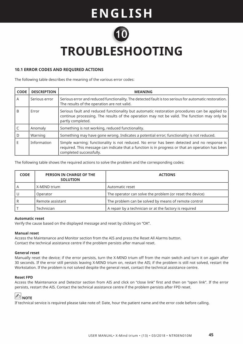
TROUBLESHOOTING10.1 ERROR CODES AND REQUIRED ACTIONS
The following table describes the meaning of the various error codes:
CODE DESCRIPTION MEANING
A Serious error Serious error and reduced functionality. The detected fault is too serious for automatic restoration. The results of the operation are not valid.
B Error Serious fault and reduced functionality but automatic restoration procedures can be applied to continue processing. The results of the operation may not be valid. The function may only be partly completed.
C Anomaly Something is not working, reduced functionality.
D Warning Something may have gone wrong. Indicates a potential error; functionality is not reduced.
E Information Simple warning; functionality is not reduced. No error has been detected and no response is required. This message can indicate that a function is in progress or that an operation has been completed successfully.
The following table shows the required actions to solve the problem and the corresponding codes:
CODE PERSON IN CHARGE OF THE SOLUTION
ACTIONS
A X-MIND trium Automatic reset
U Operator The operator can solve the problem (or reset the device)
R Remote assistant The problem can be solved by means of remote control
T Technician A repair by a technician or at the factory is required
Automatic resetVerify the cause based on the displayed message and reset by clicking on “OK”.
Manual resetAccess the Maintenance and Monitor section from the AIS and press the Reset All Alarms button.Contact the technical assistance centre if the problem persists after manual reset.
General resetManually reset the device; if the error persists, turn the X-MIND trium off from the main switch and turn it on again after 30 seconds. If the error still persists leaving X-MIND trium on, restart the AIS; if the problem is still not solved, restart the Workstation. If the problem is not solved despite the general reset, contact the technical assistance centre.
Reset FPDAccess the Maintenance and Detector section from AIS and click on “close link” first and then on “open link”. If the error persists, restart the AIS. Contact the technical assistance centre if the problem persists after FPD reset.
NOTE If technical service is required please take note of: Date, hour the patient name and the error code before calling.

46 USER MANUAL• X-Mind trium • (13) • 03/2018 • NTR0EN010M
ENGLISH
10.2 TRIUM ERRORS
CODE Ser Message / Description Act Solution
0 C
CHECK INTERNAL ETHERNETHw errror: Main board and ETHERNET switch do not communicate
In this condition X-MIND trium and workstation cannot communicate; THIS ERROR APPEARS ONLY ON THE X-MIND trium DISPLAY.
U/TReset error from AIS software on workstation; if error remains restart X-MIND trium and workstation;If error remains technical service is required.
13 C Image detector not grabbing U/T
Reset error from AIS software on workstation; if error remains restart X-MIND trium and workstation;if error remains, in case of CEPH or PAN detector, detach it from the equipment and attach it again, ascertaining to lock it correctly:if error remains technical service is required.
66 E"CONFIG_INFO_UPDATED Configuration data have been updated"
U/TRestart X-MIND trium and workstation in order that modifications will be effective.
67 D
"MOTOR_AXES_DO_BREAK WARNING: operator has intentionally stopped a movement releasing XRay button"
UWait that the full exam procedure is completed before releasing X-ray button: on the workstation will appear the message “exposure button can be released”.
68 B"MOTOR_AXES_CNTL_FSM Unexpected motors FSM condition"
AReset error from AIS software on workstation; if error remains restart X-MIND trium and workstation.
69 C"MOTOR_AXES_TRJ_LOAD Trajectory loading from PC is failed"
AReset error from AIS software on workstation; if error remains restart X-MIND trium and workstation.
70 C"XRAYS_DISA_ETH_LINK Xrays disabled due to ETH connection failure"
U/TReset error from AIS software on workstation; if error remains restart X-MIND trium and workstation; If error remains technical service is required.
71 C"XRAYS_DISA_PC_ALARM Xrays disabled due an alarm issued from PC"
U/TReset error from AIS software on workstation; if error remains restart X-MIND trium and workstation; If error remains technical service is required.
72 C"PCDRV_COMM_WDOG_ERR PC communication timeout"
U/T
Reset error from AIS software on workstation; if error remains restart X-MIND trium and workstation;Try to disable anti-virus and firewall If error remains technical service is required.
73 B"X_AXIS_ERR_RES_RAMP Unexpected FSM condition during X-axis reset"
AReset error from AIS software on workstation; if error remains restart X-MIND trium and workstation;
74 C"X_AXIS_ERR_RES_TOUT X-axis reset timeout (Uarm movement parallel to the wall)"
U/TReset error from AIS software on workstation; if error remains restart X-MIND trium and workstation;If error remains technical service is required.
75 B"Y_AXIS_ERR_RES_RAMP Unexpected FSM condition during Y-axis reset"
AReset error from AIS software on workstation; if error remains restart X-MIND trium and workstation;

47
ENGLISH
USER MANUAL• X-Mind trium • (13) • 03/2018 • NTR0EN010M
76 C"Y_AXIS_ERR_RES_TOUT Y-axis reset timeout (Uarm movement perpendicular to the wall)"
U/TReset error from AIS software on workstation; if error remains restart X-MIND trium and workstation;If error remains technical service is required.
77 B"R_AXIS_ERR_RES_RAMP Unexpected FSM condition during R-axis reset"
AReset error from AIS software on workstation; if error remains restart X-MIND trium and workstation;
78 C"R_AXIS_ERR_RES_TOUT R-axis reset timeout (Uarm rotation)"
U/TReset error from AIS software on workstation; if error remains restart X-MIND trium and workstation;If error remains technical service is required.
79 B"C_AXIS_ERR_RES_RAMP Unexpected FSM condition during B-axis reset"
AReset error from AIS software on workstation; if error remains restart X-MIND trium and workstation;
80 C"C_AXIS_ERR_RES_TOUT C-axis reset timeout (CEPH image detector slider)"
U/TReset error from AIS software on workstation; if error remains restart X-MIND trium and workstation;If error remains technical service is required.
81 B"S_AXIS_ERR_RES_RAMP Unexpected FSM condition during S-axis reset"
AReset error from AIS software on workstation; if error remains restart X-MIND trium and workstation;
82 C"S_AXIS_ERR_RES_TOUT S-axis reset timeout (image detectors slider on Uarm)"
U/TReset error from AIS software on workstation; if error remains restart X-MIND trium and workstation;If error remains technical service is required.
83 B"B_AXIS_ERR_RES_RAMP Unexpected FSM condition during B-axis reset"
AReset error from AIS software on workstation; if error remains restart X-MIND trium and workstation;
84 C"B_AXIS_ERR_RES_TOUT B-axis reset timeout (bite block vertical movement)"
U/TReset error from AIS software on workstation; if error remains restart X-MIND trium and workstation;If error remains technical service is required.
85 C
"R_AXIS_ERR_POT_BLCK R-axis potentiometer (Uarm) blocked (readings not coherent with movement)"
U/TReset error from AIS software on workstation; if error remains restart X-MIND trium and workstation;If error remains technical service is required.
86 B
"R_AXIS_ERR_POT_RAMP Unexpected FSM condition during R-axis reset positioning based on potentiometer value"
AReset error from AIS software on workstation; if error remains restart X-MIND trium and workstation;
87 B"R_AXIS_ENC_HW_FATAL Hardware error on R-axis encoder"
TReset error from AIS software on workstation; if error remains restart X-MIND trium and workstation;If error remains technical service is required.
88 C"R_AXIS_ENC_CNT_ZERO Zero-search for R-axis encoder is failed"
TReset error from AIS software on workstation; if error remains restart X-MIND trium and workstation;If error remains technical service is required.
89 B"X_AXIS_ERR_RUN_PTPT Unexpected FSM condition during X-axis position adjustment"
AReset error from AIS software on workstation; if error remains restart X-MIND trium and workstation;
90 B"Y_AXIS_ERR_RUN_PTPT Unexpected FSM condition during Y-axis position adjustment"
AReset error from AIS software on workstation; if error remains restart X-MIND trium and workstation;
91 B"B_AXIS_ERR_RUN_PTPT Unexpected FSM condition during B-axis position adjustment"
AReset error from AIS software on workstation; if error remains restart X-MIND trium and workstation;

48 USER MANUAL• X-Mind trium • (13) • 03/2018 • NTR0EN010M
ENGLISH
92 C"R_AXIS_ERR_RUN_LIMI R-axis position out of range"
AReset error from AIS software on workstation; if error remains restart X-MIND trium and workstation;
93 C"HI_VOLT_ENA_IN_IDLE XRay button activated when not allowed"
U/T
Reset error from AIS software on workstation; if error remains restart X-MIND trium and workstation;If error remains technical service is required. (Probably, someone pushed exposure button accidentally)
94 C"INVERTER_LINK_ERROR CAN communication error between Mainboard and Inverter"
TReset error from AIS software on workstation; if error remains restart X-MIND trium and workstation;If error remains technical service is required.
95 B"FW_UPDATED_CANT_EXE Cannot exec firmware after update (board need hardware reset)"
TReset error from AIS software on workstation; if error remains restart X-MIND trium and workstation;
96 C
"EEPROM_DEVICE_ERROR Inverter board error: GENERAL STATE ERROR, bit 0 - EEPROM"
TReset error from AIS software on workstation; if error remains restart X-MIND trium and workstation;If error remains technical service is required.
97 C
"EEPROM_DMA_RD_ERROR Inverter board error: GENERAL STATE ERROR, bit 1 - EEPROM READ DMA FAILURE"
TReset error from AIS software on workstation; if error remains restart X-MIND trium and workstation;If error remains technical service is required.
98 C
"EEPROM_DMA_WR_ERROR Inverter board error: GENERAL STATE ERROR, bit 2 - EEPROM WRITE DMA FAILURE"
TReset error from AIS software on workstation; if error remains restart X-MIND trium and workstation;If error remains technical service is required.
99 C
"EEPROM_I2CBUS_ERROR Inverter board error: GENERAL STATE ERROR, bit 3 - EEPROM I2CBUS"
TReset error from AIS software on workstation; if error remains restart X-MIND trium and workstation;If error remains technical service is required.
100 C
"ANOD_CURR_NOT_CALIB Inverter board error: GENERAL STATE ERROR, bit 4 - ANODIC CURRENT NOT CALIBRATED"
TReset error from AIS software on workstation; if error remains restart X-MIND trium and workstation;If error remains technical service is required.
101 C
"HI_VOLT_ENA_IN_IDLE Inverter board error: GENERAL STATE ERROR, bit 5 - HV ENABLE SIGNAL ACTIVE IN IDLE MODE"
TReset error from AIS software on workstation; if error remains restart X-MIND trium and workstation;If error remains technical service is required.
102 C
"PRE_HEAT_NOT_FINISH Inverter board error: GENERAL STATE ERROR, bit 6 - FILAMENT PRE HEATING NOT COMPLETED"
TReset error from AIS software on workstation; if error remains restart X-MIND trium and workstation;If error remains technical service is required.
103 C
"OVER_VOLTAGE_ON_POS Inverter board error: GENERAL STATE ERROR, bit 8 - OVERVOLTAGE ON POSITIVE STAGE"
TReset error from AIS software on workstation; if error remains restart X-MIND trium and workstation;If error remains technical service is required.
104 C
"OVER_VOLTAGE_ON_NEG Inverter board error: GENERAL STATE ERROR, bit 9 - OVERVOLTAGE ON NEGATIVE STAGE"
TReset error from AIS software on workstation; if error remains restart X-MIND trium and workstation;If error remains technical service is required.
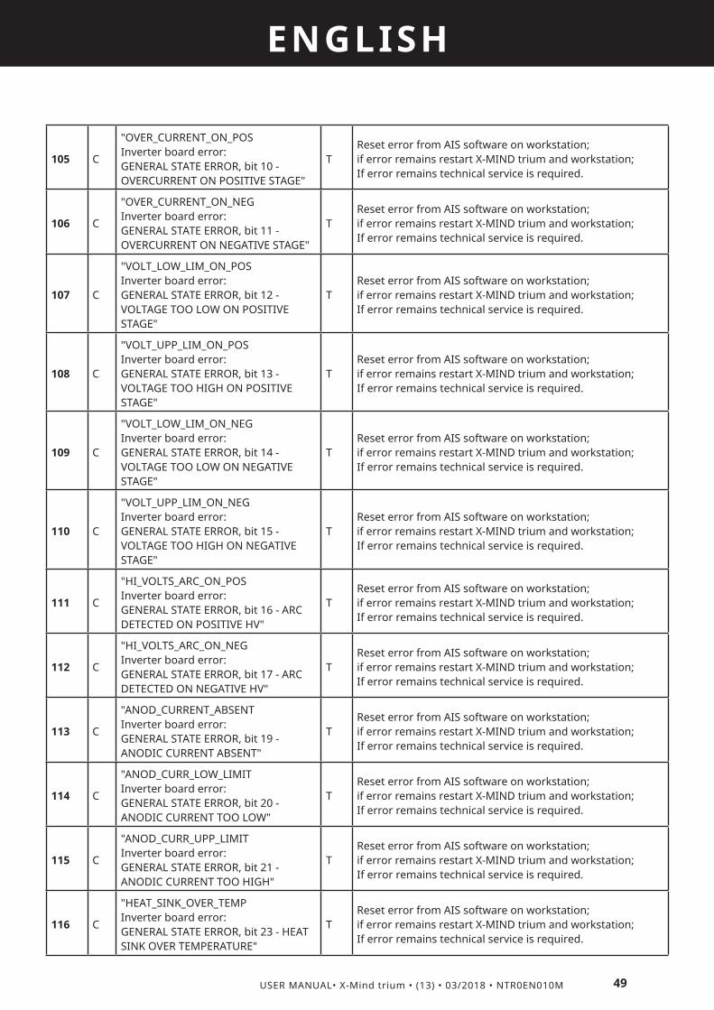
49
ENGLISH
USER MANUAL• X-Mind trium • (13) • 03/2018 • NTR0EN010M
105 C
"OVER_CURRENT_ON_POS Inverter board error: GENERAL STATE ERROR, bit 10 - OVERCURRENT ON POSITIVE STAGE"
TReset error from AIS software on workstation; if error remains restart X-MIND trium and workstation;If error remains technical service is required.
106 C
"OVER_CURRENT_ON_NEG Inverter board error: GENERAL STATE ERROR, bit 11 - OVERCURRENT ON NEGATIVE STAGE"
TReset error from AIS software on workstation; if error remains restart X-MIND trium and workstation;If error remains technical service is required.
107 C
"VOLT_LOW_LIM_ON_POS Inverter board error: GENERAL STATE ERROR, bit 12 - VOLTAGE TOO LOW ON POSITIVE STAGE"
TReset error from AIS software on workstation; if error remains restart X-MIND trium and workstation;If error remains technical service is required.
108 C
"VOLT_UPP_LIM_ON_POS Inverter board error: GENERAL STATE ERROR, bit 13 - VOLTAGE TOO HIGH ON POSITIVE STAGE"
TReset error from AIS software on workstation; if error remains restart X-MIND trium and workstation;If error remains technical service is required.
109 C
"VOLT_LOW_LIM_ON_NEG Inverter board error: GENERAL STATE ERROR, bit 14 - VOLTAGE TOO LOW ON NEGATIVE STAGE"
TReset error from AIS software on workstation; if error remains restart X-MIND trium and workstation;If error remains technical service is required.
110 C
"VOLT_UPP_LIM_ON_NEG Inverter board error: GENERAL STATE ERROR, bit 15 - VOLTAGE TOO HIGH ON NEGATIVE STAGE"
TReset error from AIS software on workstation; if error remains restart X-MIND trium and workstation;If error remains technical service is required.
111 C
"HI_VOLTS_ARC_ON_POS Inverter board error: GENERAL STATE ERROR, bit 16 - ARC DETECTED ON POSITIVE HV"
TReset error from AIS software on workstation; if error remains restart X-MIND trium and workstation;If error remains technical service is required.
112 C
"HI_VOLTS_ARC_ON_NEG Inverter board error: GENERAL STATE ERROR, bit 17 - ARC DETECTED ON NEGATIVE HV"
TReset error from AIS software on workstation; if error remains restart X-MIND trium and workstation;If error remains technical service is required.
113 C
"ANOD_CURRENT_ABSENT Inverter board error: GENERAL STATE ERROR, bit 19 - ANODIC CURRENT ABSENT"
TReset error from AIS software on workstation; if error remains restart X-MIND trium and workstation;If error remains technical service is required.
114 C
"ANOD_CURR_LOW_LIMIT Inverter board error: GENERAL STATE ERROR, bit 20 - ANODIC CURRENT TOO LOW"
TReset error from AIS software on workstation; if error remains restart X-MIND trium and workstation;If error remains technical service is required.
115 C
"ANOD_CURR_UPP_LIMIT Inverter board error: GENERAL STATE ERROR, bit 21 - ANODIC CURRENT TOO HIGH"
TReset error from AIS software on workstation; if error remains restart X-MIND trium and workstation;If error remains technical service is required.
116 C
"HEAT_SINK_OVER_TEMP Inverter board error: GENERAL STATE ERROR, bit 23 - HEAT SINK OVER TEMPERATURE"
TReset error from AIS software on workstation; if error remains restart X-MIND trium and workstation;If error remains technical service is required.
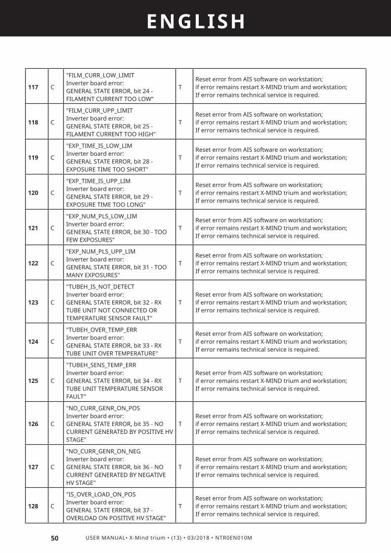
50 USER MANUAL• X-Mind trium • (13) • 03/2018 • NTR0EN010M
ENGLISH
117 C
"FILM_CURR_LOW_LIMIT Inverter board error: GENERAL STATE ERROR, bit 24 - FILAMENT CURRENT TOO LOW"
TReset error from AIS software on workstation; if error remains restart X-MIND trium and workstation;If error remains technical service is required.
118 C
"FILM_CURR_UPP_LIMIT Inverter board error: GENERAL STATE ERROR, bit 25 - FILAMENT CURRENT TOO HIGH"
TReset error from AIS software on workstation; if error remains restart X-MIND trium and workstation;If error remains technical service is required.
119 C
"EXP_TIME_IS_LOW_LIM Inverter board error: GENERAL STATE ERROR, bit 28 - EXPOSURE TIME TOO SHORT"
TReset error from AIS software on workstation; if error remains restart X-MIND trium and workstation;If error remains technical service is required.
120 C
"EXP_TIME_IS_UPP_LIM Inverter board error: GENERAL STATE ERROR, bit 29 - EXPOSURE TIME TOO LONG"
TReset error from AIS software on workstation; if error remains restart X-MIND trium and workstation;If error remains technical service is required.
121 C
"EXP_NUM_PLS_LOW_LIM Inverter board error: GENERAL STATE ERROR, bit 30 - TOO FEW EXPOSURES"
TReset error from AIS software on workstation; if error remains restart X-MIND trium and workstation;If error remains technical service is required.
122 C
"EXP_NUM_PLS_UPP_LIM Inverter board error: GENERAL STATE ERROR, bit 31 - TOO MANY EXPOSURES"
TReset error from AIS software on workstation; if error remains restart X-MIND trium and workstation;If error remains technical service is required.
123 C
"TUBEH_IS_NOT_DETECT Inverter board error: GENERAL STATE ERROR, bit 32 - RX TUBE UNIT NOT CONNECTED OR TEMPERATURE SENSOR FAULT"
TReset error from AIS software on workstation; if error remains restart X-MIND trium and workstation;If error remains technical service is required.
124 C
"TUBEH_OVER_TEMP_ERR Inverter board error: GENERAL STATE ERROR, bit 33 - RX TUBE UNIT OVER TEMPERATURE"
TReset error from AIS software on workstation; if error remains restart X-MIND trium and workstation;If error remains technical service is required.
125 C
"TUBEH_SENS_TEMP_ERR Inverter board error: GENERAL STATE ERROR, bit 34 - RX TUBE UNIT TEMPERATURE SENSOR FAULT"
TReset error from AIS software on workstation; if error remains restart X-MIND trium and workstation;If error remains technical service is required.
126 C
"NO_CURR_GENR_ON_POS Inverter board error: GENERAL STATE ERROR, bit 35 - NO CURRENT GENERATED BY POSITIVE HV STAGE"
TReset error from AIS software on workstation; if error remains restart X-MIND trium and workstation;If error remains technical service is required.
127 C
"NO_CURR_GENR_ON_NEG Inverter board error: GENERAL STATE ERROR, bit 36 - NO CURRENT GENERATED BY NEGATIVE HV STAGE"
TReset error from AIS software on workstation; if error remains restart X-MIND trium and workstation;If error remains technical service is required.
128 C
"IS_OVER_LOAD_ON_POS Inverter board error: GENERAL STATE ERROR, bit 37 - OVERLOAD ON POSITIVE HV STAGE"
TReset error from AIS software on workstation; if error remains restart X-MIND trium and workstation;If error remains technical service is required.
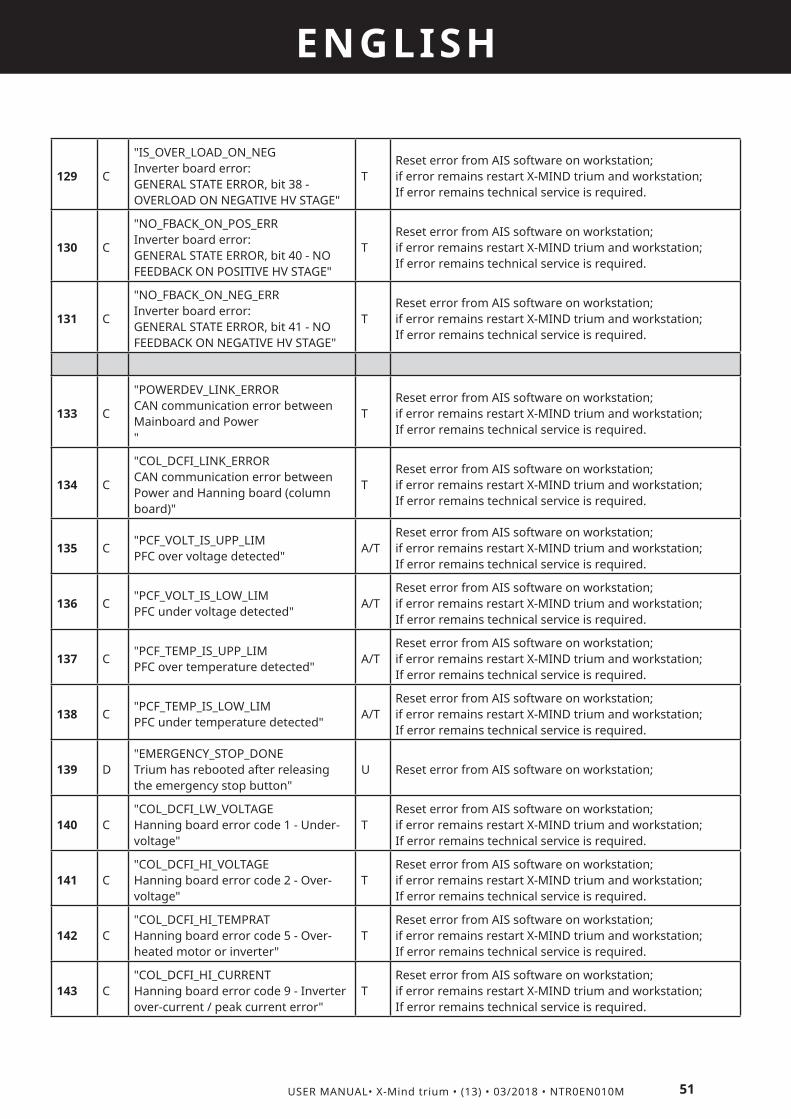
51
ENGLISH
USER MANUAL• X-Mind trium • (13) • 03/2018 • NTR0EN010M
129 C
"IS_OVER_LOAD_ON_NEG Inverter board error: GENERAL STATE ERROR, bit 38 - OVERLOAD ON NEGATIVE HV STAGE"
TReset error from AIS software on workstation; if error remains restart X-MIND trium and workstation;If error remains technical service is required.
130 C
"NO_FBACK_ON_POS_ERR Inverter board error: GENERAL STATE ERROR, bit 40 - NO FEEDBACK ON POSITIVE HV STAGE"
TReset error from AIS software on workstation; if error remains restart X-MIND trium and workstation;If error remains technical service is required.
131 C
"NO_FBACK_ON_NEG_ERR Inverter board error: GENERAL STATE ERROR, bit 41 - NO FEEDBACK ON NEGATIVE HV STAGE"
TReset error from AIS software on workstation; if error remains restart X-MIND trium and workstation;If error remains technical service is required.
133 C
"POWERDEV_LINK_ERROR CAN communication error between Mainboard and Power "
TReset error from AIS software on workstation; if error remains restart X-MIND trium and workstation;If error remains technical service is required.
134 C
"COL_DCFI_LINK_ERROR CAN communication error between Power and Hanning board (column board)"
TReset error from AIS software on workstation; if error remains restart X-MIND trium and workstation;If error remains technical service is required.
135 C"PCF_VOLT_IS_UPP_LIM PFC over voltage detected"
A/TReset error from AIS software on workstation; if error remains restart X-MIND trium and workstation;If error remains technical service is required.
136 C"PCF_VOLT_IS_LOW_LIM PFC under voltage detected"
A/TReset error from AIS software on workstation; if error remains restart X-MIND trium and workstation;If error remains technical service is required.
137 C"PCF_TEMP_IS_UPP_LIM PFC over temperature detected"
A/TReset error from AIS software on workstation; if error remains restart X-MIND trium and workstation;If error remains technical service is required.
138 C"PCF_TEMP_IS_LOW_LIM PFC under temperature detected"
A/TReset error from AIS software on workstation; if error remains restart X-MIND trium and workstation;If error remains technical service is required.
139 D"EMERGENCY_STOP_DONE Trium has rebooted after releasing the emergency stop button"
U Reset error from AIS software on workstation;
140 C"COL_DCFI_LW_VOLTAGE Hanning board error code 1 - Under-voltage"
TReset error from AIS software on workstation; if error remains restart X-MIND trium and workstation;If error remains technical service is required.
141 C"COL_DCFI_HI_VOLTAGE Hanning board error code 2 - Over-voltage"
TReset error from AIS software on workstation; if error remains restart X-MIND trium and workstation;If error remains technical service is required.
142 C"COL_DCFI_HI_TEMPRAT Hanning board error code 5 - Over-heated motor or inverter"
TReset error from AIS software on workstation; if error remains restart X-MIND trium and workstation;If error remains technical service is required.
143 C"COL_DCFI_HI_CURRENT Hanning board error code 9 - Inverter over-current / peak current error"
TReset error from AIS software on workstation; if error remains restart X-MIND trium and workstation;If error remains technical service is required.

52 USER MANUAL• X-Mind trium • (13) • 03/2018 • NTR0EN010M
ENGLISH
144 C"COL_DCFI_SHORT_CIRC Hanning board error code 13 - Short-circuit – shut down"
TReset error from AIS software on workstation; if error remains restart X-MIND trium and workstation;If error remains technical service is required.
145 C"COL_DCFI_IS_NOT_ENA Hanning board error code 16 - Not enabled"
TReset error from AIS software on workstation; if error remains restart X-MIND trium and workstation;If error remains technical service is required.
146 C"COL_DCFI_TXCMD_TOUT Hanning board error code 17 - Time-out – digital interface"
TReset error from AIS software on workstation; if error remains restart X-MIND trium and workstation;If error remains technical service is required.
147 C"COL_DCFI_ON_DIR_ERR Hanning board error code 18 - Start attempt with directional error"
TReset error from AIS software on workstation; if error remains restart X-MIND trium and workstation;If error remains technical service is required.
148 C"COL_DCFI_TIMING_ERR Hanning board error code 128 - Internal timing error"
TReset error from AIS software on workstation; if error remains restart X-MIND trium and workstation;If error remains technical service is required.
149 C"COL_DCFI_SYSTEM_ERR Hanning board error code 129 - System error"
TReset error from AIS software on workstation; if error remains restart X-MIND trium and workstation;If error remains technical service is required.
150 C"COL_DCFI_WDOG_RESET Hanning board error code 131 - Reset by Watch Dog"
TReset error from AIS software on workstation; if error remains restart X-MIND trium and workstation;If error remains technical service is required.
151 C"COL_DCFI_VDIP_RESET Hanning board error code 132 - Reset by voltage dip (brown-out)"
TReset error from AIS software on workstation; if error remains restart X-MIND trium and workstation;If error remains technical service is required.
152 C"COL_DCFI_SFTW_RESET Hanning board error code 133 - Reset by SW"
TReset error from AIS software on workstation; if error remains restart X-MIND trium and workstation;If error remains technical service is required.
153 C"COL_DCFI_E2PROM_CRC Hanning board error code 140 - Parameter memory CRC error"
TReset error from AIS software on workstation; if error remains restart X-MIND trium and workstation;If error remains technical service is required.
154 C
"COL_DCFI_E2PROM_TAB Hanning board error code 141 - Parameter memory table has an error"
TReset error from AIS software on workstation; if error remains restart X-MIND trium and workstation;If error remains technical service is required.
155 C
"COL_DCFI_DFLT_TABLE Hanning board error code 142 - Parameter memory factory default table has an error"
TReset error from AIS software on workstation; if error remains restart X-MIND trium and workstation;If error remains technical service is required.
156 C
"COLUMN_POS_WDG_TOUT Column motion stopped due to CAN communication timeout between Mainbord and Power"
TReset error from AIS software on workstation; if error remains restart X-MIND trium and workstation;If error remains technical service is required.
157 C
"COLUMN_POS_END_LIMI Column motion stopped because of the achievement of mechanical limit switches"
U/T
Reset error from AIS software on workstation.Move the column in the opposite direction.The equipment can be operated, but the occurrence of this error means that the column potentiometer is out of calibration; technical service is required:

53
ENGLISH
USER MANUAL• X-Mind trium • (13) • 03/2018 • NTR0EN010M
158 B
"COLUMN_POS_RUN_LIMI Column motion stopped because of the achievement of calibrated upper or lower position"
UOnly a warning: operator can move in the opposite direction.
159 C"COLUMN_POT_REF_LIMI Reference value for column potentiometer is out of range"
TReset error from AIS software on workstation; if error remains restart X-MIND trium and workstation;If error remains technical service is required.
160 C"COLUMN_POT_POS_LIMI Read value of column potentiometer is out of range"
TReset error from AIS software on workstation; if error remains restart X-MIND trium and workstation;If error remains technical service is required.
161 C"COLUMN_POT_POS_BLCK Column motion stopped because of the column potentiometer is blocked"
TReset error from AIS software on workstation; if error remains restart X-MIND trium and workstation;If error remains technical service is required.
163 C"AUX_CBCT_LINK_ERROR CAN communication error between Mainboard and AUX CBCT board"
TReset error from AIS software on workstation; if error remains restart X-MIND trium and workstation;If error remains technical service is required.
164 B"AUX_CEPH_LINK_ERROR CAN communication error between Mainboard and AUX CEPH board"
TReset error from AIS software on workstation; if error remains restart X-MIND trium and workstation;If error remains technical service is required.
165 C
"PRM_COLLIM_DO_BREAK WARNING: operator has intentionally stopped a movement releasing XRay button"
UWait the full exam procedure is completed before releasing XRay button: message on workstation “exposure button can be released”
166 C"PRM_COLLIM_CNTL_FSM Unexpected primary collimator FSM condition"
AReset error from AIS software on workstation; if error remains restart X-MIND trium and workstation;
167 B
"VERT_INF_RESET_RAMP Unexpected FSM condition during reset of primary collimator vertical-inf axis"
AReset error from AIS software on workstation; if error remains restart X-MIND trium and workstation;
168 C"VERT_INF_RESET_TOUT Timeout of primary collimator vertical-inf axis reset"
U/TReset error from AIS software on workstation; if error remains restart X-MIND trium and workstation;If error remains technical service is required.
169 C
"VERT_INF_PT_PT_GOTO The point-to-point positioning of vertical-inf axis of primary collimator is failed"
AReset error from AIS software on workstation; if error remains restart X-MIND trium and workstation;
170 B
"VERT_SUP_RESET_RAMP Unexpected FSM condition during reset of primary collimator vertical-sup axis"
AReset error from AIS software on workstation; if error remains restart X-MIND trium and workstation;
171 C"VERT_SUP_RESET_TOUT Timeout of primary collimator vertical-sup axis reset"
U/TReset error from AIS software on workstation; if error remains restart X-MIND trium and workstation;If error remains technical service is required.
172 C
"VERT_SUP_PT_PT_GOTO The point-to-point positioning of vertical-sup axis of primary collimator is failed"
AReset error from AIS software on workstation; if error remains restart X-MIND trium and workstation;

54 USER MANUAL• X-Mind trium • (13) • 03/2018 • NTR0EN010M
ENGLISH
173 B
"HORZ_ONE_RESET_RAMP Unexpected FSM condition during reset of primary collimator horizontal axis"
AReset error from AIS software on workstation; if error remains restart X-MIND trium and workstation;
174 C"HORZ_ONE_RESET_TOUT Timeout of primary collimator horizontal axis reset"
U/TReset error from AIS software on workstation; if error remains restart X-MIND trium and workstation;If error remains technical service is required.
175 C
"HORZ_ONE_PT_PT_GOTO The point-to-point positioning of horizontal axis of primary collimator is failed"
AReset error from AIS software on workstation; if error remains restart X-MIND trium and workstation;
177 C
"XRAYS_EXAM_DO_BREAK WARNING: operator has intentionally stopped the Xray emission releasing XRay button"
UWait the full exam procedure is completed before releasing XRay button: message onworkstation “exposure button can be released”

11
55
ENGLISH
USER MANUAL• X-Mind trium • (13) • 03/2018 • NTR0EN010M
ANNEXES11.1 DEVICE POWER SUPPLY
Type of power supply Single-phase alternating current power supply
Supply voltage 100 – 240 V
Maximum voltage variation ±10%
Frequency 50 – 60 Hz
Absorbed current (@ 90 kV, 10 mA) 7 A (@ 240 V)15 A (@ 100 V)
Standby current 1 A
Maximum absorbed power 1500 VA
Line fuses T 250 VH 10 A (for power supply range: 200 – 240 V)T 250 VH 20 A (for power supply range: 100 – 200 V)
Apparent resistance 0.2 Ω
11.2 ELECTRICAL CLASSIFICATION (IEC 60601-1)
Protection against electrical shock (insulation class) Class I
Degree of protection against electrical shock (Applied part) TYPE B
Use with flammable anaesthetics Not evaluated for use in presence of flammable anaesthetic mixture with air, oxygen or nitrous oxide
Sterilization and disinfection methods The device is supplied not sterile and it must not be subjected to sterilization
Operation mode Continuous operation with intermittent X-ray loading
Installation type Permanently Installed (fixed installation)
11.3 X-RAY ASSEMBLY AND X-RAY TUBE
X-RAY TUBE MODEL CEI OPX/105
Nominal High Voltage 60 – 90 kV
Anode Material Tungsten
Anode thermal capacity 30 kJ
Focal spot size (IEC 60336) 0.5 mm x 0.5 mm
Target angle 5°

56 USER MANUAL• X-Mind trium • (13) • 03/2018 • NTR0EN010M
ENGLISH
Reference axis position
CBCT
PAN
CEPH
HVL1 3.4 mm Al for PAN/CEPH at 85 kV5.2 mm Al for CBCT at 90 kV
Total filtration2 2.8 mm Al for PAN/CEPH at 85 kV 7.0 mm Al for CBCT at 90 kV
Inherent filtration 0.5 mm Al
Leakage radiation3 < 0.88 mGy/h @ 1 m
X-ray voltage accuracy ± 10%4
X-ray current accuracy ± 20%5
Radiation linearity ± 20%6
X-ray emission time accuracy ± (10% + 1 ms)7

57
ENGLISH
USER MANUAL• X-Mind trium • (13) • 03/2018 • NTR0EN010M
Current-time product accuracy ± (10% + 0.2 mAs)8
Dose reproducibility9 <0.05
Maximum anodic current 10 mA (typical 8 mA)
Loading factors related to the maximum specified energy input in one hour
Continuous mode: 85 kVp @ 10 mA
Nominal X-ray Tube Voltage together with the highest X-ray Tube Current obtainable from the High-Voltage Generator when operated at that X-ray Tube Voltage
Pulsed mode: 90kVp @ 10 mA
Highest X-ray Tube Current together with the highest X-ray Tube Voltage obtainable from the High-Voltage Generator when operating at that X-ray Tube Current
Pulsed mode: 10 mA 90 kVp
The Combination of X-ray Tube Voltage and X-ray Tube Current which results in the highest electric output power
Pulsed mode: 90 kVp @ 10 mA
The lowest Current Time Product or the combinations of Loading Factors resulting in the lowest Current Time Product
0.04 mAs per frame
Nominal electrical power 1.1 kW @ 90 kV, 10 mA, 0.1 s loading time
X-ray emission technology/ mode of operation DC High FrequencyPAN/CEPH:- Continuous X-ray loading.- Combinations of kV and mA along the whole maximum exposure time. (Maximum combination of loading factors in continuous mode is 85 kV @ 10 mA).CBCT:- Intermitting X-ray loading.- Combinations of kV and mA with a maximum combination of loading factors: 90 kV @ 10 mA.
Loading factors for Leakage radiation measurement 90 kVp @ 10 mA
Focal Spot-to-Skin distance10 ≥ 150 mm
1 IEC 60601-1-3 Par. 7.1 - 21 CFR 1020.30 (m)2 IEC 60601-1-3 Par. 7.13 21 CFR 1020.30 (k) 4 IEC 60601-2-63 Par. 203.6.4.3.102.2 – 21 CFR 1020.31 (a) (4)5 IEC 60601-2-63 Par. 203.6.4.3.102.3 – 21 CFR 1020.31 (a) (4)6 IEC 60601-2-63 Par. 203.6.3.1.101 – 21 CFR 1020.31 (c)7 IEC 60601-2-63 Par. 203.6.4.3.102.4 – 21 CFR 1020.31 (a) (4)8 IEC 60601-2-63 Par. 203.6.4.3.102.5 – 21 CFR 1020.31 (a) (4)9 IEC 60601-2-63 Par. 203.6.3.2.101 – 21 CFR 1020.31 (b)10 IEC 60601-2-63 Par. 203.9 – 21 CFR 1020.31 (f)
11.4 DEGREE OF PROTECTION PROVIDED BY ENCLOSURES
According to the standard IEC 60529, the degree of protection is IP20

58 USER MANUAL• X-Mind trium • (13) • 03/2018 • NTR0EN010M
ENGLISH
11.5 DEVICE MECHANICAL DATA
Dimensions Footprint: Max 1505 x 1715 mmHeight: 2358 mm
Weight PAN: 170 kgPAN/CBCT: 185 kgPAN/CBCT With CEPH: 215 kg
Mechanical configuration Wall mount / Self standingLeft column/Right columnPatient position: Standing, seated or on wheel-chair
11.6 WORKSTATION FEATURES
CBCT WORKSTATION PROVIDED BY THE MANUFACTURER
CPU 6th Gen Intel(R) Core(TM) i5-6500 (Quad Core 3.2GHz)
Hard Disk 1 TB
Graphic Processor NVIDIA (CUDA environment GPU family) Like :Quadro P2000
RAM 8 GB
NIC Dedicated Gb Ethernet for X-MIND Trium Connection
Operating System Windows 7 Professional 64 bit.
Certifications IEC 60950-1, CISPR 22, CISPR 24
PAN/CEPHMINIMUM REQUIREMENTS
CPU INTEL I5 or superior
Hard Disk 1TB 7200 rpm or superior
Graphic Processor OPEN GL 2.1 compatible (suggested an NVIDIA GT/GTX)
RAM 8 GB
NIC INTEL CT 1000 pro
Operating System Windows 7 Professional 64 bit or Windows 10 Professional 64 bit
11.7 DETECTORS
PAN/CEPH
Detector technology CMOS
Scintillator Direct deposition CsI
Manufacturer Hamamatsu Photonics K.K.
ModelPAN: FPD C10500D-43CEPH: FPD C10502D-43G
Pixel size 100 µm
Active areaPAN: 148 mm x 6 mmCEPH: 223,2 mm x 6 mm

59
ENGLISH
USER MANUAL• X-Mind trium • (13) • 03/2018 • NTR0EN010M
Image sizePAN: 1480 px x 2658 pxCEPH: 2232 px x 2673 px
Image formatPAN: 1480 mm x 2600 mmCEPH: 2000mm x 2200 mm, 2000mm x 1800 mm, 2400mm x 2200 mm, 2400mm x 1800 mm
Frame rate 300 frames/s
Sensitivity 12000 LSB/mR
Resolution 4.5 lp/mm
Dynamic range 4300
CBCT
Detector technology CMOS
Scintillator Direct deposited CsI
Manufacturer Hamamatsu Photonics K.K.
Model FPD C12280D-40
Image voxel size 75 µm (minimum slice thickness)
Active area 121.6 x 123.1 mm
FOV (diameter x height)
40 mm x 60 mm60 mm x 60 mm80 mm x 80 mm110 mm x 80 mm
NOTE :A specific version of AIS software disables FOV 110mm X 80mm
Frame rate 35 frames/s
Sensitivity 6000 LSB/mR
Resolution 2.5 lp/mm
Dynamic range 3600
11.8 SCANNING PARAMETERS – PAN/CEPH
X-ray exposure time PAN: 3.3 s – 13.5 s / CEPH:18 s
Scanning time PAN: 16.8 s – 22.5 s / CEPH: 23 s
Tube voltage 60 – 85 kVp
Anodic current 4 – 10 mA
11.9 SCANNING PARAMETERS – CBCT
Scanning time 12 s – 30 s
Rotation 360°
X-ray real exposure time6s (Standard quality)7.2s (Medium quality)9s (High quality)
Tube voltage 80 - 90 kVp
Anodic current 4 – 10 mA

60 USER MANUAL• X-Mind trium • (13) • 03/2018 • NTR0EN010M
ENGLISH
11.10 LASER
Laser type Line Wavelength Operating voltage
Class Diffractive optics
Power P o s i t i o n i n g accuracy
PAN mid-sagittalfrom patient arm
Single line 635-650 nm 2.7 to 5 V 1M Line, 90° 0.3 mW <1mm
Canine from Tubehead
Single line 635-650 nm 2.7 to 5 V 1M Line, 90° 0.3 mW <1mm
Frankfurtfrom Tubehead
Multi-line 635-650 nm 2.7 to 5 V 3R Line, 90° 0.3 - 2 mW <1mm
CBCT mid-sagittalfrom U-arm
Single line 635-650 nm 2.7 to 5 V 1M Line, 90° 0.3 mW <1mm
CBCT coronalfrom Tubehead
Single line 635-650 nm 2.7 to 5 V 1M Line, 90° 0.3 mW <1mm
Axial (horizontal)from Tubehead.
Single line 635-650 nm 2.7 to 5 V 1M Line, 90° 0.3 mW <1mm
11.11 FIRMWARE DATA
Main board 0.44.3
Power board 0.10.3
Inverter board 2.4.0
AUX CBCT board 0.7.0
UX CEPH board 0.3.0
Image detectors 2.5.27
11.12 CLIENT PC MINIMUM REQUIREMENTS
IT’S MANDATORY TO RESPECT CLIENT PC MINIMUM REQUIREMENTS
THE CHOICE OF PC FOR AIS CLIENT, IS UNDER CUSTOMER RESPONSIBILITY. A WRONG CHOICE, WITHOUT RESPECTING MINIMUM REQUIREMENT, WILL NOT BE UNDER ACTEON GROUP RESPONSIBILITY.
Please, take care about workstation minimum requirement to avoid faults, errors, misfunctionality and/or problem during the installation, connection and use of X-MIND Trium.
CLIENT:WINDOWS OS BASED HARDWAREProcessor: Intel I5 or I7 (notebooks), Quad Core suggested (for Workstations)RAM: minimum 4 GB, for big FOV DICOM stacks it is suggested to install 8 GB Hard disk: minimum 300 GB (for image storage, the software alone occupies 200 MB, the full implant library is 7 Gb size)Graphic card: Nvidia Geforce product range with 1 Gb dedicated RAM (notebooks) or Nvidia Quadro with dedicated memory (workstations)Screen resolution: minimum height 1024 and width 1600, it is suggested to use higher resolutions for optimal planning (full HD: 1920 x 1080)O/S: Windows 7 (64 bit), Windows 10 (64 bit).
MAC OS BASED HARDWARE

61
ENGLISH
USER MANUAL• X-Mind trium • (13) • 03/2018 • NTR0EN010M
Macbook PRO product line oriMac product line with the following or equivalent characteristics:RAM: minimum 4 GB, for big FOV DICOM stacks it is suggested to install 8 GB.Hard disk: minimum 300 GB (for image storage, the software alone occupies 200 MB, the full implant library is 7 Gb size)Graphic card for optimal performance: Nvidia Geforce product range or Nvidia Quadro with 1 Gb dedicated RAM.Screen resolution: minimum height 1024 and width 1600, it is suggested to use higher resolutions for optimal planning (full HD: 1920 x 1080)O/S: OS X Sierra (10.12).
Network Cards : A LAN network must be used for the connection between client and server. Avoid to use a wireless network card on the client : fast connection network (LAN type) are needed to share the patient exams with the clients PCs. Due to this, a WiFi network card could be too slow to transfer patient exams with clients PCs.
OTHER SOFTWARE :• If you install an antivirus or firewall or internet security in the workstation, take care of these specific :- All the AIS processes have to be excluded in AV the exclusion list- All the ports used by AIS (from 51000 to 51020, and 6543) have to be opened in the firewall- If you face other problems or you are not able to configure AV or firewall, please disable them.
PAY ATTENTION TO DON’T HAVE AIS WORKSTATION SOFTWARE VERSION ALREADY INSTALLED IN THE MACHINE. OTHERWISE YOU WILL HAVE PROBLEM IN THE INSTAL-LATION AND IN THE CONFIGURATION AIS CLIENT VERSION !
11.13 INTENDED ENVIRONMENT
Clinical environment conditions (use conditions):• Temperature: 10 to 30°C• Relative humidity: 25 to 75 %• Atmospheric pressure: 850 to 1060 hPa
Transportation environment conditions: • Temperature: 0 to 50°C• Relative humidity: See clinical environment conditions• Atmospheric pressure: 500 to 1060 hPa
Warehousing environment conditions: • See Transportation environment conditions
11.14 DIMENSIONS OF THE UNIT
PAN/CBCT
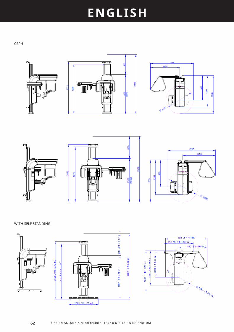
62 USER MANUAL• X-Mind trium • (13) • 03/2018 • NTR0EN010M
ENGLISH
CEPH
WITH SELF STANDING

63
ENGLISH
USER MANUAL• X-Mind trium • (13) • 03/2018 • NTR0EN010M
11.15 LIST OF INTERNATIONAL STANDARDS AND DIRECTIVES
The system is classified as:
Directive MDD 93/42 EECAnnex IX, article 10
21CFR892.1750
SOR 98/282rule 8
TG(MD) Regulations 2002Schedule 2 part 4.3
Pharmaceuticals and Medical Devices Act
[Table 1]
Class IIb II III IIb II
IEC/EN 60601-1:2005, 3nd edition IEC/EN 60601-1-3:2008, IEC/EN 60601-1-6:2010, IEC 62366: 2007IEC 60601-2-63:2012ANSI/AAMI ES60601-1:2005CAN/CSA-C222.2 N. 60601-1:08IEC/EN 60601-2: 200721 CFR 1020.3021 CFR 1020.3121 CFR 1020.33
11.16 DOSIMETRIC INDICATIONS
The following tables provides dosimetric indications related to the execution of radiographic exams by the X-MIND trium.The radiation dose is reported in terms of Dose Area Product (DAP), which takes into account the size of the X-ray beam and its intensity, providing a thorough dose index; in detail, the DAP is computed by multiplying the Air Kerma measured by the X-ray beam area at the measurement location.The DAP is considered beneficial for the following reasons:· It is dependent by the typology of beam limiting device installed and in use· It is independent by the measured location, that is the distance from the focal spotThis section reports the value of radiation dose for every type of exam and any combination of loading factors.Typically, these dosimetric indications represents a reference for the operators to adjust or modify the loading factors during the process of optimization of the scanning protocol; in addition, these values might be used for dosimetric check during installation or periodic maintenance to assess the proper functioning of the device.

Exposure Time
[s] 13,5 7,28 8,2 4,98 4,24 7,9 12,38 7,16 10,74 7,16 10,74 14,34 6,94 2,9
[kV] [mA]
Tube
vol
tage
Anod
ic c
urre
nt
PAN
sta
ndar
d
PAN
sta
ndar
d Ri
ght/
Left
[mGycm2]
PAN
ort
hogo
nal
Righ
t/Le
ft
PAN
fron
tal
Bite
win
gs
PAN
Mot
or
Child
TMJ
fron
tal
TMJ
fron
tal
Righ
t/Le
ft
PAN
ort
hogo
nal
TMJ
late
ral
TMJ
late
ral
Righ
t/Le
ft
TMJ
stan
dard
SIN
US
fron
tal
SIN
US
late
ral
Righ
t/Le
ft
64 USER MANUAL• X-Mind trium • (13) • 03/2018 • NTR0EN010M
ENGLISH
DAP values for PANORAMIC exams

Exposure Time
[s] 13,5 7,28 8,2 4,98 4,24 7,9 12,38 7,16 10,74 7,16 10,74 14,34 6,94 2,9
[kV] [mA]
Tube
vol
tage
Anod
ic c
urre
nt
PAN
sta
ndar
d
PAN
sta
ndar
d Ri
ght/
Left
[mGycm2]
PAN
ort
hogo
nal
Righ
t/Le
ft
PAN
fron
tal
Bite
win
gs
PAN
Mot
or
Child
TMJ
fron
tal
TMJ
fron
tal
Righ
t/Le
ft
PAN
ort
hogo
nal
TMJ
late
ral
TMJ
late
ral
Righ
t/Le
ft
TMJ
stan
dard
SIN
US
fron
tal
SIN
US
late
ral
Righ
t/Le
ft
65
ENGLISH
USER MANUAL• X-Mind trium • (13) • 03/2018 • NTR0EN010M

Exposure Time
[s] 13,5 7,28 8,2 4,98 4,24 7,9 12,38 7,16 10,74 7,16 10,74 14,34 6,94 2,9
[kV] [mA]
Tube
vol
tage
Anod
ic c
urre
nt
PAN
sta
ndar
d
PAN
sta
ndar
d Ri
ght/
Left
[mGycm2]
PAN
ort
hogo
nal
Righ
t/Le
ft
PAN
fron
tal
Bite
win
gs
PAN
Mot
or
Child
TMJ
fron
tal
TMJ
fron
tal
Righ
t/Le
ft
PAN
ort
hogo
nal
TMJ
late
ral
TMJ
late
ral
Righ
t/Le
ft
TMJ
stan
dard
SIN
US
fron
tal
SIN
US
late
ral
Righ
t/Le
ft
66 USER MANUAL• X-Mind trium • (13) • 03/2018 • NTR0EN010M
ENGLISH

67
ENGLISH
USER MANUAL• X-Mind trium • (13) • 03/2018 • NTR0EN010M
DAP values for CBCT exams
Patient gender Patient size Tube voltage
[kV]Tube current
[mA]
Dental FOV 40x40
Standard Medium High
[mGycm^2] [mGycm^2] [mGycm^2]
CHILD
SMALL 80 6 140,4 168,5 210,6
MEDIUM 80 8 187,2 224,6 280,8
LARGE 80 10 234,0 280,8 350,9
WOMAN
SMALL 85 6 165,4 198,5 248,2
MEDIUM 85 8 220,6 264,7 330,9
LARGE 85 10 275,7 330,9 413,6
MAN
SMALL 90 6 190,5 228,6 285,7
MEDIUM 90 8 254,0 304,8 381,0
LARGE 90 10 317,5 381,0 476,2
Patient gender Patient size Tube voltage
[kV]Tube current
[mA]
Dental FOV 60x60
Standard Medium High
[mGycm^2] [mGycm^2] [mGycm^2]
CHILD
SMALL 80 6 359,6 431,5 539,3
MEDIUM 80 8 479,4 575,3 719,1
LARGE 80 10 599,3 719,1 898,9
WOMAN
SMALL 85 6 424,3 509,2 636,5
MEDIUM 85 8 565,7 678,9 848,6
LARGE 85 10 707,2 848,6 1060,8
MAN
SMALL 90 6 489,1 586,9 733,6
MEDIUM 90 8 652,1 782,5 978,1
LARGE 90 10 815,1 978,1 1222,7
Patient gender Patient size Tube voltage
[kV]Tube current
[mA]
Dental FOV 80x80 / 110x80
Standard Medium High
[mGycm^2] [mGycm^2] [mGycm^2]
CHILD
SMALL 80 6 414,0 496,8 621,0
MEDIUM 80 8 552,0 662,5 828,1
LARGE 80 10 690,1 828,1 1035,1
WOMAN
SMALL 85 6 489,1 586,9 733,7
MEDIUM 85 8 652,1 782,6 978,2
LARGE 85 10 815,2 978,2 1222,8

68 USER MANUAL• X-Mind trium • (13) • 03/2018 • NTR0EN010M
ENGLISH
MAN
SMALL 90 6 564,2 677,0 846,3
MEDIUM 90 8 752,2 902,7 1128,4
LARGE 90 10 940,3 1128,4 1410,4

60 4 9,9 8,2 12,1 9,7 8,060 5 12,4 10,2 15,1 12,1 10,060 6 14,9 12,3 18,1 14,5 12,060 7 17,4 14,3 21,1 16,9 14,060 8 19,9 16,4 24,2 19,4 16,060 9 22,4 18,4 27,2 21,8 18,060 10 24,9 20,5 30,2 24,2 20,061 4 10,3 8,5 12,6 10,1 8,361 5 12,9 10,6 15,8 12,6 10,461 6 15,4 12,7 18,9 15,1 12,461 7 18,0 14,8 22,1 17,6 14,561 8 20,6 16,9 25,2 20,1 16,661 9 23,2 19,1 28,4 22,7 18,761 10 25,7 21,2 31,6 25,2 20,762 4 10,7 8,7 13,2 10,5 8,662 5 13,3 10,9 16,5 13,1 10,862 6 16,0 13,1 19,7 15,7 12,962 7 18,6 15,3 23,0 18,3 15,162 8 21,3 17,5 26,3 20,9 17,262 9 24,0 19,7 29,6 23,5 19,462 10 26,6 21,9 32,9 26,1 21,563 4 11,0 9,0 13,7 10,8 8,963 5 13,8 11,3 17,1 13,5 11,163 6 16,5 13,5 20,6 16,3 13,463 7 19,3 15,8 24,0 19,0 15,663 8 22,0 18,0 27,4 21,7 17,863 9 24,8 20,3 30,8 24,4 20,163 10 27,5 22,6 34,3 27,1 22,364 4 11,4 9,3 14,3 11,2 9,264 5 14,2 11,6 17,8 14,0 11,564 6 17,0 13,9 21,4 16,8 13,864 7 19,9 16,3 24,9 19,6 16,164 8 22,7 18,6 28,5 22,4 18,464 9 25,6 20,9 32,1 25,2 20,764 10 28,4 23,2 35,6 28,1 23,065 4 11,7 9,6 14,8 11,6 9,565 5 14,6 12,0 18,5 14,5 11,965 6 17,6 14,4 22,2 17,4 14,365 7 20,5 16,8 25,9 20,3 16,765 8 23,4 19,1 29,6 23,2 19,065 9 26,4 21,5 33,3 26,1 21,465 10 29,3 23,9 37,0 29,0 23,866 4 12,1 9,8 15,3 12,0 9,8
CEPH AP/PA Child
CARPUS
[mGycm^2]
Tube voltage [kV]
Tube current [mA]
CEPH LLCEPH LL
ChildCEPH AP/PA
69
ENGLISH
USER MANUAL• X-Mind trium • (13) • 03/2018 • NTR0EN010M
DAP values for CEPH group exams

CEPH AP/PA Child
CARPUS
[mGycm^2]
Tube voltage [kV]
Tube current [mA]
CEPH LLCEPH LL
ChildCEPH AP/PA
66 5 15,1 12,3 19,2 15,0 12,366 6 18,1 14,8 23,0 18,0 14,766 7 21,1 17,2 26,8 21,0 17,266 8 24,1 19,7 30,7 24,0 19,766 9 27,1 22,2 34,5 27,0 22,166 10 30,2 24,6 38,4 30,0 24,667 4 12,4 10,1 15,9 12,4 10,167 5 15,5 12,7 19,9 15,5 12,767 6 18,6 15,2 23,8 18,6 15,267 7 21,7 17,7 27,8 21,7 17,767 8 24,8 20,2 31,8 24,7 20,367 9 27,9 22,8 35,7 27,8 22,867 10 31,0 25,3 39,7 30,9 25,368 4 12,8 10,4 16,4 12,8 10,468 5 16,0 13,0 20,5 15,9 13,168 6 19,2 15,6 24,6 19,1 15,768 7 22,4 18,2 28,8 22,3 18,368 8 25,5 20,8 32,9 25,5 20,968 9 28,7 23,4 37,0 28,7 23,568 10 31,9 26,0 41,1 31,9 26,169 4 13,1 10,7 17,0 13,1 10,769 5 16,4 13,3 21,2 16,4 13,469 6 19,7 16,0 25,5 19,7 16,169 7 23,0 18,7 29,7 23,0 18,869 8 26,3 21,4 33,9 26,3 21,569 9 29,5 24,0 38,2 29,6 24,269 10 32,8 26,7 42,4 32,9 26,970 4 13,5 11,0 17,5 13,5 11,170 5 16,8 13,7 21,9 16,9 13,870 6 20,2 16,4 26,3 20,3 16,670 7 23,6 19,2 30,7 23,7 19,370 8 27,0 21,9 35,0 27,1 22,170 9 30,3 24,6 39,4 30,4 24,970 10 33,7 27,4 43,8 33,8 27,671 4 13,8 11,2 18,1 13,9 11,471 5 17,3 14,0 22,6 17,4 14,271 6 20,7 16,8 27,1 20,9 17,071 7 24,2 19,6 31,6 24,3 19,971 8 27,7 22,5 36,1 27,8 22,771 9 31,1 25,3 40,6 31,3 25,671 10 34,6 28,1 45,2 34,8 28,472 4 14,2 11,5 18,6 14,3 11,772 5 17,7 14,4 23,3 17,9 14,6
70 USER MANUAL• X-Mind trium • (13) • 03/2018 • NTR0EN010M
ENGLISH

CEPH AP/PA Child
CARPUS
[mGycm^2]
Tube voltage [kV]
Tube current [mA]
CEPH LLCEPH LL
ChildCEPH AP/PA
72 6 21,3 17,3 27,9 21,4 17,572 7 24,8 20,1 32,6 25,0 20,472 8 28,4 23,0 37,2 28,6 23,372 9 31,9 25,9 41,9 32,2 26,372 10 35,5 28,8 46,5 35,7 29,273 4 14,5 11,8 19,1 14,7 12,073 5 18,2 14,7 23,9 18,4 15,073 6 21,8 17,7 28,7 22,0 18,073 7 25,4 20,6 33,5 25,7 21,073 8 29,1 23,6 38,3 29,4 24,073 9 32,7 26,5 43,1 33,0 26,973 10 36,3 29,4 47,9 36,7 29,974 4 14,9 12,1 19,7 15,1 12,374 5 18,6 15,1 24,6 18,8 15,474 6 22,3 18,1 29,5 22,6 18,474 7 26,1 21,1 34,5 26,4 21,574 8 29,8 24,1 39,4 30,1 24,674 9 33,5 27,1 44,3 33,9 27,674 10 37,2 30,1 49,2 37,7 30,775 4 15,2 12,3 20,2 15,5 12,675 5 19,1 15,4 25,3 19,3 15,775 6 22,9 18,5 30,4 23,2 18,975 7 26,7 21,6 35,4 27,0 22,075 8 30,5 24,7 40,5 30,9 25,275 9 34,3 27,7 45,5 34,8 28,375 10 38,1 30,8 50,6 38,6 31,576 4 15,6 12,6 20,8 15,8 12,976 5 19,5 15,8 26,0 19,8 16,176 6 23,4 18,9 31,2 23,8 19,376 7 27,3 22,1 36,4 27,7 22,676 8 31,2 25,2 41,6 31,7 25,876 9 35,1 28,4 46,8 35,6 29,076 10 39,0 31,5 52,0 39,6 32,277 4 16,0 12,9 21,3 16,2 13,277 5 19,9 16,1 26,7 20,3 16,577 6 23,9 19,3 32,0 24,3 19,877 7 27,9 22,5 37,3 28,4 23,177 8 31,9 25,8 42,7 32,4 26,477 9 35,9 29,0 48,0 36,5 29,777 10 39,9 32,2 53,3 40,5 33,078 4 16,3 13,2 21,9 16,6 13,578 5 20,4 16,4 27,3 20,8 16,978 6 24,5 19,7 32,8 24,9 20,3
71
ENGLISH
USER MANUAL• X-Mind trium • (13) • 03/2018 • NTR0EN010M
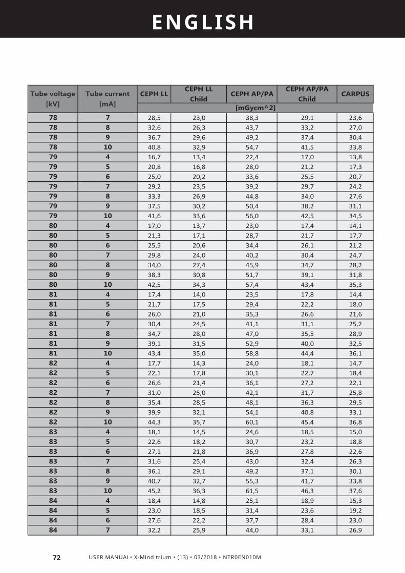
CEPH AP/PA Child
CARPUS
[mGycm^2]
Tube voltage [kV]
Tube current [mA]
CEPH LLCEPH LL
ChildCEPH AP/PA
78 7 28,5 23,0 38,3 29,1 23,678 8 32,6 26,3 43,7 33,2 27,078 9 36,7 29,6 49,2 37,4 30,478 10 40,8 32,9 54,7 41,5 33,879 4 16,7 13,4 22,4 17,0 13,879 5 20,8 16,8 28,0 21,2 17,379 6 25,0 20,2 33,6 25,5 20,779 7 29,2 23,5 39,2 29,7 24,279 8 33,3 26,9 44,8 34,0 27,679 9 37,5 30,2 50,4 38,2 31,179 10 41,6 33,6 56,0 42,5 34,580 4 17,0 13,7 23,0 17,4 14,180 5 21,3 17,1 28,7 21,7 17,780 6 25,5 20,6 34,4 26,1 21,280 7 29,8 24,0 40,2 30,4 24,780 8 34,0 27,4 45,9 34,7 28,280 9 38,3 30,8 51,7 39,1 31,880 10 42,5 34,3 57,4 43,4 35,381 4 17,4 14,0 23,5 17,8 14,481 5 21,7 17,5 29,4 22,2 18,081 6 26,0 21,0 35,3 26,6 21,681 7 30,4 24,5 41,1 31,1 25,281 8 34,7 28,0 47,0 35,5 28,981 9 39,1 31,5 52,9 40,0 32,581 10 43,4 35,0 58,8 44,4 36,182 4 17,7 14,3 24,0 18,1 14,782 5 22,1 17,8 30,1 22,7 18,482 6 26,6 21,4 36,1 27,2 22,182 7 31,0 25,0 42,1 31,7 25,882 8 35,4 28,5 48,1 36,3 29,582 9 39,9 32,1 54,1 40,8 33,182 10 44,3 35,7 60,1 45,4 36,883 4 18,1 14,5 24,6 18,5 15,083 5 22,6 18,2 30,7 23,2 18,883 6 27,1 21,8 36,9 27,8 22,683 7 31,6 25,4 43,0 32,4 26,383 8 36,1 29,1 49,2 37,1 30,183 9 40,7 32,7 55,3 41,7 33,883 10 45,2 36,3 61,5 46,3 37,684 4 18,4 14,8 25,1 18,9 15,384 5 23,0 18,5 31,4 23,6 19,284 6 27,6 22,2 37,7 28,4 23,084 7 32,2 25,9 44,0 33,1 26,9
72 USER MANUAL• X-Mind trium • (13) • 03/2018 • NTR0EN010M
ENGLISH
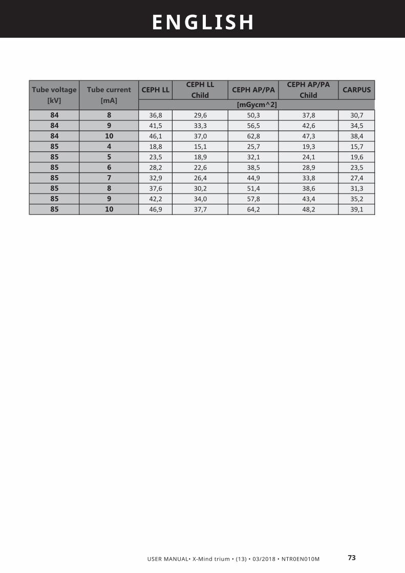
CEPH AP/PA Child
CARPUS
[mGycm^2]
Tube voltage [kV]
Tube current [mA]
CEPH LLCEPH LL
ChildCEPH AP/PA
84 8 36,8 29,6 50,3 37,8 30,784 9 41,5 33,3 56,5 42,6 34,584 10 46,1 37,0 62,8 47,3 38,485 4 18,8 15,1 25,7 19,3 15,785 5 23,5 18,9 32,1 24,1 19,685 6 28,2 22,6 38,5 28,9 23,585 7 32,9 26,4 44,9 33,8 27,485 8 37,6 30,2 51,4 38,6 31,385 9 42,2 34,0 57,8 43,4 35,285 10 46,9 37,7 64,2 48,2 39,1
73
ENGLISH
USER MANUAL• X-Mind trium • (13) • 03/2018 • NTR0EN010M

74 USER MANUAL• X-Mind trium • (13) • 03/2018 • NTR0EN010M
ENGLISH
11.16.2 DOSIMETRIC INDICATIONS IN TERMS OF CTDI (FOR CBCT EXAMS)
The following tables provide dosimetric indications related to the execution of CBCT exams using X-MIND trium.The radiation dose is reported in terms of Computed Tomography Dose Index (CTDI), which represents the integral of dose profile along a line perpendicular to the tomographic plane divided by the product of the nominal tomographic section thickness and the number of tomograms produced in a single scan.CTDI values were measured setting the following loading factors and without the application of any filter:
Patient gender Patient size Tube Voltage [kV] Anodic Current [mA]
Man
Small 90 6
Medium 90 8
Large 90 10
Woman
Small 85 6
Medium 85 8
Large 85 10
Child
Small 80 6
Medium 80 8
Large 80 10
The dosimetry phantom used to perform the test is the QUART DVT_AP. All dose measurements were performed with the CT dosimetry phantom placed on a support device, without additional attenuating materials present.
The following table reports the CTDI values measured at the indicated locations in the dosimetry phantom, with the typical settings suggested for a CBCT exam using X-MIND trium (e.g. Man Medium, FOV 40x40):
Location CTDI [mGy]
Along the axis of rotation 2,86
Along a line parallel to the axis of rotation and 1.0 cm interior to the surface of the phantom
1.25
Along a line parallel to the axis of rotation and 1.0 centimeter interior to the surface of the phantom at position 90 degrees from the position b)
1.12
Along a line parallel to the axis of rotation and 1.0 centimeter interior to the surface of the phantom at position 180 degrees from the position b)
1.17
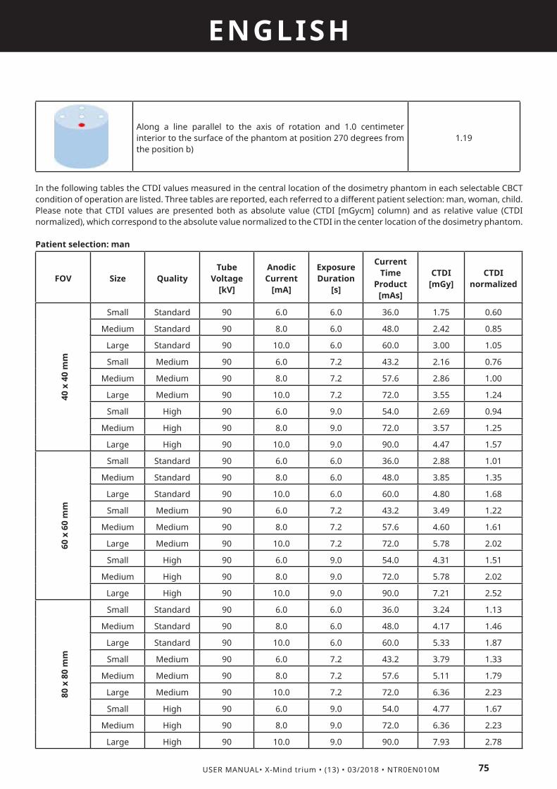
75
ENGLISH
USER MANUAL• X-Mind trium • (13) • 03/2018 • NTR0EN010M
Along a line parallel to the axis of rotation and 1.0 centimeter interior to the surface of the phantom at position 270 degrees from the position b)
1.19
In the following tables the CTDI values measured in the central location of the dosimetry phantom in each selectable CBCT condition of operation are listed. Three tables are reported, each referred to a different patient selection: man, woman, child.Please note that CTDI values are presented both as absolute value (CTDI [mGycm] column) and as relative value (CTDI normalized), which correspond to the absolute value normalized to the CTDI in the center location of the dosimetry phantom.
Patient selection: man
FOV Size QualityTube
Voltage [kV]
Anodic Current
[mA]
Exposure Duration
[s]
Current Time
Product [mAs]
CTDI [mGy]
CTDI normalized
40 x
40
mm
Small Standard 90 6.0 6.0 36.0 1.75 0.60
Medium Standard 90 8.0 6.0 48.0 2.42 0.85
Large Standard 90 10.0 6.0 60.0 3.00 1.05
Small Medium 90 6.0 7.2 43.2 2.16 0.76
Medium Medium 90 8.0 7.2 57.6 2.86 1.00
Large Medium 90 10.0 7.2 72.0 3.55 1.24
Small High 90 6.0 9.0 54.0 2.69 0.94
Medium High 90 8.0 9.0 72.0 3.57 1.25
Large High 90 10.0 9.0 90.0 4.47 1.57
60 x
60
mm
Small Standard 90 6.0 6.0 36.0 2.88 1.01
Medium Standard 90 8.0 6.0 48.0 3.85 1.35
Large Standard 90 10.0 6.0 60.0 4.80 1.68
Small Medium 90 6.0 7.2 43.2 3.49 1.22
Medium Medium 90 8.0 7.2 57.6 4.60 1.61
Large Medium 90 10.0 7.2 72.0 5.78 2.02
Small High 90 6.0 9.0 54.0 4.31 1.51
Medium High 90 8.0 9.0 72.0 5.78 2.02
Large High 90 10.0 9.0 90.0 7.21 2.52
80 x
80
mm
Small Standard 90 6.0 6.0 36.0 3.24 1.13
Medium Standard 90 8.0 6.0 48.0 4.17 1.46
Large Standard 90 10.0 6.0 60.0 5.33 1.87
Small Medium 90 6.0 7.2 43.2 3.79 1.33
Medium Medium 90 8.0 7.2 57.6 5.11 1.79
Large Medium 90 10.0 7.2 72.0 6.36 2.23
Small High 90 6.0 9.0 54.0 4.77 1.67
Medium High 90 8.0 9.0 72.0 6.36 2.23
Large High 90 10.0 9.0 90.0 7.93 2.78
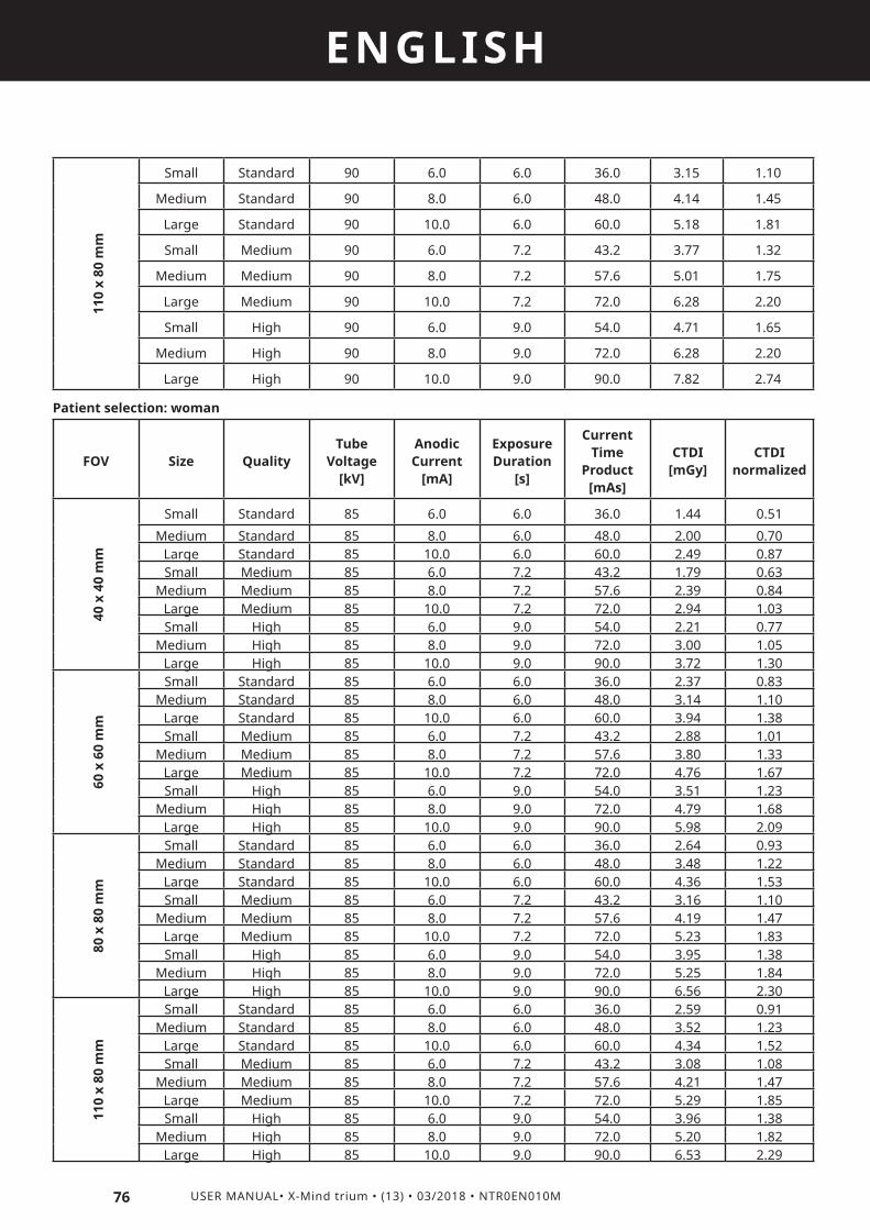
76 USER MANUAL• X-Mind trium • (13) • 03/2018 • NTR0EN010M
ENGLISH
Patient selection: woman
FOV Size QualityTube
Voltage [kV]
Anodic Current
[mA]
Exposure Duration
[s]
Current Time
Product [mAs]
CTDI [mGy]
CTDI normalized
40 x
40
mm
Small Standard 85 6.0 6.0 36.0 1.44 0.51
Medium Standard 85 8.0 6.0 48.0 2.00 0.70Large Standard 85 10.0 6.0 60.0 2.49 0.87Small Medium 85 6.0 7.2 43.2 1.79 0.63
Medium Medium 85 8.0 7.2 57.6 2.39 0.84Large Medium 85 10.0 7.2 72.0 2.94 1.03Small High 85 6.0 9.0 54.0 2.21 0.77
Medium High 85 8.0 9.0 72.0 3.00 1.05Large High 85 10.0 9.0 90.0 3.72 1.30
60 x
60
mm
Small Standard 85 6.0 6.0 36.0 2.37 0.83Medium Standard 85 8.0 6.0 48.0 3.14 1.10
Large Standard 85 10.0 6.0 60.0 3.94 1.38Small Medium 85 6.0 7.2 43.2 2.88 1.01
Medium Medium 85 8.0 7.2 57.6 3.80 1.33Large Medium 85 10.0 7.2 72.0 4.76 1.67Small High 85 6.0 9.0 54.0 3.51 1.23
Medium High 85 8.0 9.0 72.0 4.79 1.68Large High 85 10.0 9.0 90.0 5.98 2.09
80 x
80
mm
Small Standard 85 6.0 6.0 36.0 2.64 0.93Medium Standard 85 8.0 6.0 48.0 3.48 1.22
Large Standard 85 10.0 6.0 60.0 4.36 1.53Small Medium 85 6.0 7.2 43.2 3.16 1.10
Medium Medium 85 8.0 7.2 57.6 4.19 1.47Large Medium 85 10.0 7.2 72.0 5.23 1.83Small High 85 6.0 9.0 54.0 3.95 1.38
Medium High 85 8.0 9.0 72.0 5.25 1.84Large High 85 10.0 9.0 90.0 6.56 2.30
110
x 80
mm
Small Standard 85 6.0 6.0 36.0 2.59 0.91Medium Standard 85 8.0 6.0 48.0 3.52 1.23
Large Standard 85 10.0 6.0 60.0 4.34 1.52Small Medium 85 6.0 7.2 43.2 3.08 1.08
Medium Medium 85 8.0 7.2 57.6 4.21 1.47Large Medium 85 10.0 7.2 72.0 5.29 1.85Small High 85 6.0 9.0 54.0 3.96 1.38
Medium High 85 8.0 9.0 72.0 5.20 1.82Large High 85 10.0 9.0 90.0 6.53 2.29
110
x 80
mm
Small Standard 90 6.0 6.0 36.0 3.15 1.10
Medium Standard 90 8.0 6.0 48.0 4.14 1.45
Large Standard 90 10.0 6.0 60.0 5.18 1.81
Small Medium 90 6.0 7.2 43.2 3.77 1.32
Medium Medium 90 8.0 7.2 57.6 5.01 1.75
Large Medium 90 10.0 7.2 72.0 6.28 2.20
Small High 90 6.0 9.0 54.0 4.71 1.65
Medium High 90 8.0 9.0 72.0 6.28 2.20
Large High 90 10.0 9.0 90.0 7.82 2.74

77
ENGLISH
USER MANUAL• X-Mind trium • (13) • 03/2018 • NTR0EN010M
Patient selection: child
FOV Size QualityTube
Voltage [kV]
Anodic Current
[mA]
Exposure Duration
[s]
Current Time
Product [mAs]
CTDI [mGy]
CTDI normalized
40 x
40
mm
Small Standard 80 6.0 6.0 36.0 1.17 0.59
Medium Standard 80 8.0 6.0 48.0 1.59 0.80
Large Standard 80 10.0 6.0 60.0 1.94 0.97
Small Medium 80 6.0 7.2 43.2 1.51 0.76
Medium Medium 80 8.0 7.2 57.6 1.99 1.00
Large Medium 80 10.0 7.2 72.0 2.50 1.26
Small High 80 6.0 9.0 54.0 1.85 0.93
Medium High 80 8.0 9.0 72.0 2.55 0.41
Large High 80 10.0 9.0 90.0 3.08 0.56
60 x
60
mm
Small Standard 80 6.0 6.0 36.0 1.99 0.68
Medium Standard 80 8.0 6.0 48.0 2.69 0.53
Large Standard 80 10.0 6.0 60.0 3.27 0.70
Small Medium 80 6.0 7.2 43.2 2.41 0.88
Medium Medium 80 8.0 7.2 57.6 3.18 0.65
Large Medium 80 10.0 7.2 72.0 3.91 0.89
Small High 80 6.0 9.0 54.0 2.91 1.08
Medium High 80 8.0 9.0 72.0 3.99 0.70
Large High 80 10.0 9.0 90.0 4.99 0.94
80 x
80
mm
Small Standard 80 6.0 6.0 36.0 2.22 1.14
Medium Standard 80 8.0 6.0 48.0 2.90 0.85
Large Standard 80 10.0 6.0 60.0 3.64 1.11
Small Medium 80 6.0 7.2 43.2 2.51 1.37
Medium Medium 80 8.0 7.2 57.6 3.47 1.02
Large Medium 80 10.0 7.2 72.0 4.31 1.40
Small High 80 6.0 9.0 54.0 3.29 1.75
Medium High 80 8.0 9.0 72.0 4.26 0.78
Large High 80 10.0 9.0 90.0 5.38 1.01
110
x 80
mm
Small Standard 80 6.0 6.0 36.0 2.19 1.27
Medium Standard 80 8.0 6.0 48.0 2.93 0.88
Large Standard 80 10.0 6.0 60.0 3.64 1.21
Small Medium 80 6.0 7.2 43.2 2.59 1.51
Medium Medium 80 8.0 7.2 57.6 3.47 1.15
Large Medium 80 10.0 7.2 72.0 4.40 1.49
Small High 80 6.0 9.0 54.0 3.26 1.88
Medium High 80 8.0 9.0 72.0 4.36 0.77
Large High 80 10.0 9.0 90.0 5.41 1.03

78 USER MANUAL• X-Mind trium • (13) • 03/2018 • NTR0EN010M
ENGLISH
In the following tables the CTDI values measured in one of the four locations at 1 centimeter from the phantom surface in each selectable CBCT condition of operation are listed. Three tables are reported, each referred to a different patient selection: man, woman, child. Please note that CTDI values are presented both as absolute value (CTDI [mGy] column) and as relative value (CTDI normalized), which correspond to the absolute value normalized to the CTDI in the center location of the dosimetry phantom.
Patient selection: man
FOV Size QualityTube
Voltage [kV]
Anodic Current
[mA]
Exposure Duration
[s]
Current Time
Product [mAs]
CTDI [mGy]
CTDI normalized
40 x
40
mm
Small Standard 90 6.0 6.0 36.0 0.74 0.66Medium Standard 90 8.0 6.0 48.0 0.94 0.84
Large Standard 90 10.0 6.0 60.0 1.24 1.10Small Medium 90 6.0 7.2 43.2 0.74 0.66
Medium Medium 90 8.0 7.2 57.6 1.12 1.00Large Medium 90 10.0 7.2 72.0 1.41 1.26Small High 90 6.0 9.0 54.0 1.07 0.96
Medium High 90 8.0 9.0 72.0 1.38 1.23Large High 90 10.0 9.0 90.0 1.54 1.37
60 x
60
mm
Small Standard 90 6.0 6.0 36.0 1.82 1.62Medium Standard 90 8.0 6.0 48.0 2.53 2.25
Large Standard 90 10.0 6.0 60.0 3.03 2.70Small Medium 90 6.0 7.2 43.2 2.21 1.97
Medium Medium 90 8.0 7.2 57.6 2.93 2.61Large Medium 90 10.0 7.2 72.0 3.70 3.30Small High 90 6.0 9.0 54.0 2.80 2.49
Medium High 90 8.0 9.0 72.0 3.54 3.15Large High 90 10.0 9.0 90.0 4.64 4.13
80 x
80
mm
Small Standard 90 6.0 6.0 36.0 2.30 2.04
Medium Standard 90 8.0 6.0 48.0 3.06 2.72Large Standard 90 10.0 6.0 60.0 3.56 3.17Small Medium 90 6.0 7.2 43.2 2.81 2.51
Medium Medium 90 8.0 7.2 57.6 3.64 3.24Large Medium 90 10.0 7.2 72.0 4.53 4.04Small High 90 6.0 9.0 54.0 3.39 3.02
Medium High 90 8.0 9.0 72.0 4.49 4.00Large High 90 10.0 9.0 90.0 5.64 5.02

79
ENGLISH
USER MANUAL• X-Mind trium • (13) • 03/2018 • NTR0EN010M
110
x 80
mm
Small Standard 90 6.0 6.0 36.0 2.59 2.31
Medium Standard 90 8.0 6.0 48.0 3.43 3.06
Large Standard 90 10.0 6.0 60.0 4.22 3.76
Small Medium 90 6.0 7.2 43.2 3.12 2.78
Medium Medium 90 8.0 7.2 57.6 4.04 3.60
Large Medium 90 10.0 7.2 72.0 5.06 4.51
Small High 90 6.0 9.0 54.0 3.80 3.38
Medium High 90 8.0 9.0 72.0 5.03 4.49
Large High 90 10.0 9.0 90.0 6.19 5.52
Patient selection: woman
FOV Size QualityTube
Voltage [kV]
Anodic Current
[mA]
Exposure Duration
[s]
Current Time
Product [mAs]
CTDI [mGy]
CTDI normalized
40 x
40
mm
Small Standard 85 6.0 6.0 36.0 0.60 0.53
Medium Standard 85 8.0 6.0 48.0 0.85 0.76
Large Standard 85 10.0 6.0 60.0 0.87 0.78
Small Medium 85 6.0 7.2 43.2 0.71 0.63
Medium Medium 85 8.0 7.2 57.6 0.90 0.80
Large Medium 85 10.0 7.2 72.0 1.11 0.99
Small High 85 6.0 9.0 54.0 0.69 0.62
Medium High 85 8.0 9.0 72.0 1.09 0.97
Large High 85 10.0 9.0 90.0 1.36 1.21
60 x
60
mm
Small Standard 85 6.0 6.0 36.0 1.41 1.26
Medium Standard 85 8.0 6.0 48.0 2.19 1.95
Large Standard 85 10.0 6.0 60.0 2.64 2.35
Small Medium 85 6.0 7.2 43.2 1.97 1.75
Medium Medium 85 8.0 7.2 57.6 2.48 2.21
Large Medium 85 10.0 7.2 72.0 3.05 2.72
Small High 85 6.0 9.0 54.0 2.27 2.03
Medium High 85 8.0 9.0 72.0 2.80 2.50
Large High 85 10.0 9.0 90.0 3.82 3.41

80 USER MANUAL• X-Mind trium • (13) • 03/2018 • NTR0EN010M
ENGLISH80
x 8
0 m
m
Small Standard 85 6.0 6.0 36.0 1.88 1.67
Medium Standard 85 8.0 6.0 48.0 2.45 2.18
Large Standard 85 10.0 6.0 60.0 3.04 2.70
Small Medium 85 6.0 7.2 43.2 2.10 1.87
Medium Medium 85 8.0 7.2 57.6 2.81 2.50
Large Medium 85 10.0 7.2 72.0 3.59 3.20
Small High 85 6.0 9.0 54.0 2.65 2.36
Medium High 85 8.0 9.0 72.0 3.54 3.16
Large High 85 10.0 9.0 90.0 4.33 3.85
110
x 80
mm
Small Standard 85 6.0 6.0 36.0 1.97 1.76
Medium Standard 85 8.0 6.0 48.0 2.88 2.56
Large Standard 85 10.0 6.0 60.0 3.46 3.08
Small Medium 85 6.0 7.2 43.2 2.37 2.11
Medium Medium 85 8.0 7.2 57.6 3.30 2.94
Large Medium 85 10.0 7.2 72.0 4.21 3.75
Small High 85 6.0 9.0 54.0 3.24 2.89
Medium High 85 8.0 9.0 72.0 4.07 3.63
Large High 85 10.0 9.0 90.0 4.89 4.36
Patient selection: child
FOV Size QualityTube
Voltage [kV]
Anodic Current
[mA]
Exposure Duration
[s]
Current Time
Product [mAs]
CTDI [mGy]
CTDI normalized
40 x
40
mm
Small Standard 80 6.0 6.0 36.0 0.49 0.44
Medium Standard 80 8.0 6.0 48.0 0.74 0.66
Large Standard 80 10.0 6.0 60.0 0.81 0.72
Small Medium 80 6.0 7.2 43.2 0.65 0.58
Medium Medium 80 8.0 7.2 57.6 0.82 0.73
Large Medium 80 10.0 7.2 72.0 1.13 1.01
Small High 80 6.0 9.0 54.0 0.58 0.51
Medium High 80 8.0 9.0 72.0 1.07 0.95
Large High 80 10.0 9.0 80.0 1.26 1.12

81
ENGLISH
USER MANUAL• X-Mind trium • (13) • 03/2018 • NTR0EN010M
60 x
60
mm
Small Standard 80 6.0 6.0 36.0 1.18 1.05
Medium Standard 80 8.0 6.0 48.0 1.58 1.40
Large Standard 80 10.0 6.0 60.0 1.90 1.69
Small Medium 80 6.0 7.2 43.2 1.47 1.31
Medium Medium 80 8.0 7.2 57.6 1.95 1.74
Large Medium 80 10.0 7.2 72.0 2.45 2.18
Small High 80 6.0 9.0 54.0 1.80 1.60
Medium High 80 8.0 9.0 72.0 2.50 2.23
Large High 80 10.0 9.0 80.0 3.09 2.75
80 x
80
mm
Small Standard 80 6.0 6.0 36.0 1.26 1.13
Medium Standard 80 8.0 6.0 48.0 2.05 1.82
Large Standard 80 10.0 6.0 60.0 2.42 2.15
Small Medium 80 6.0 7.2 43.2 1.80 1.60
Medium Medium 80 8.0 7.2 57.6 2.35 2.10
Large Medium 80 10.0 7.2 72.0 3.03 2.70
Small High 80 6.0 9.0 54.0 2.15 1.91
Medium High 80 8.0 9.0 72.0 2.96 2.63
Large High 80 10.0 9.0 80.0 3.72 3.32
110
x 80
mm
Small Standard 80 6.0 6.0 36.0 1.78 1.59
Medium Standard 80 8.0 6.0 48.0 2.39 2.13
Large Standard 80 10.0 6.0 60.0 2.82 2.51
Small Medium 80 6.0 7.2 43.2 2.13 1.90
Medium Medium 80 8.0 7.2 57.6 2.71 2.42
Large Medium 80 10.0 7.2 72.0 3.41 3.04
Small High 80 6.0 9.0 54.0 2.41 2.15
Medium High 80 8.0 9.0 72.0 3.37 3.00
Large High 80 10.0 9.0 80.0 5.42 3.75
The following tables report the standard deviation, respectively, for peripheral and central positions in the dosimetry phantom:
STANDARD DEVIATION[mGy]
MAN 0.64
WOMAN 1.01
CHILD 0.73
STANDARD DEVIATION[mGy]
MAN 0.25
WOMAN 0.26
CHILD 0.47

82 USER MANUAL• X-Mind trium • (13) • 03/2018 • NTR0EN010M
ENGLISH
11.17 ELECTROMAGNETIC COMPATIBILITY
All the information below is based on the requirements of standards to which the manufacturers of electrical medical devices must adhere (as stated in standard IEC60601-1-2).The medical device complies with the electromagnetic compatibility standards in force. However, the user will make sure that any electromagnetic interference does not create an additional risk, such as radiofrequency transmitters, or other electronic devices.This chapter contains the information required for you to install and use your medical device in optimum conditions in terms of electromagnetic compatibility.Some types of mobile telecommunication devices, such as mobile phones, may interfere with the medical device. The separation distances recommended in this chapter MUST be respected.The medical device must not be used near another device or placed on top of it. If this cannot be avoided, correct operation of the device in operating conditions must be checked prior to use.The use of accessories other than those specified or sold by ACTEON® Imaging as replacement parts, may increase the transmission or reduce the immunity of the medical device.
11.17.1 RECOMMENDED SEPARATION DISTANCES
The medical device is designed to be used in an electromagnetic environment in which interferences caused by RF radiation are controlled.The user or installer of the medical device may help to prevent electromagnetic interference by maintaining a minimum distance, depending on the maximum power of the handheld and mobile radiofrequency transmission equipment (transmitters), between the medical device and the equipment as recommended in the table below.
Rated maximum output power of the transmitter
[W]
Separation distance according to transmitter frequency [m]
150 kHz - 80 MHzd = 1,2 √P
80 MHz - 800 MHzd = 1,2 √P
800 MHz - 2.5 GHzd = 2,3 √P
0.01 0.12 0.12 0.24
0.1 0.38 0.38 0.73
1 1,2 1.2 2.3
10 3,8 3.8 7.3
100 12 12 23
In the event of transmitters whose maximum nominal output power coefficient does not fall within the indicated parameters, the recommended separation distance in metres (m) can be determined by means of the equation corresponding to the frequency of the transmitter, where (P) is the maximum output power coefficient of the transmitter in watts (W) according to the information provided by the manufacturer.Note 1: At 80 MHz and 800 MHz apply the separation distance corresponding to the highest frequency range.Note 2: These guidelines may not apply in every situation. Electromagnetic propagation is affected by absorption and reflection from structures, objects and people.The electromagnetic propagation is affected by absorption and reflection from structures, objects and people.
11.17.2 ELECTROMAGNETIC EMISSIONS
The medical device is designed for use in the electromagnetic environment described in the table below. The user and/or installer must ensure that the medical device is used in the environment described below.
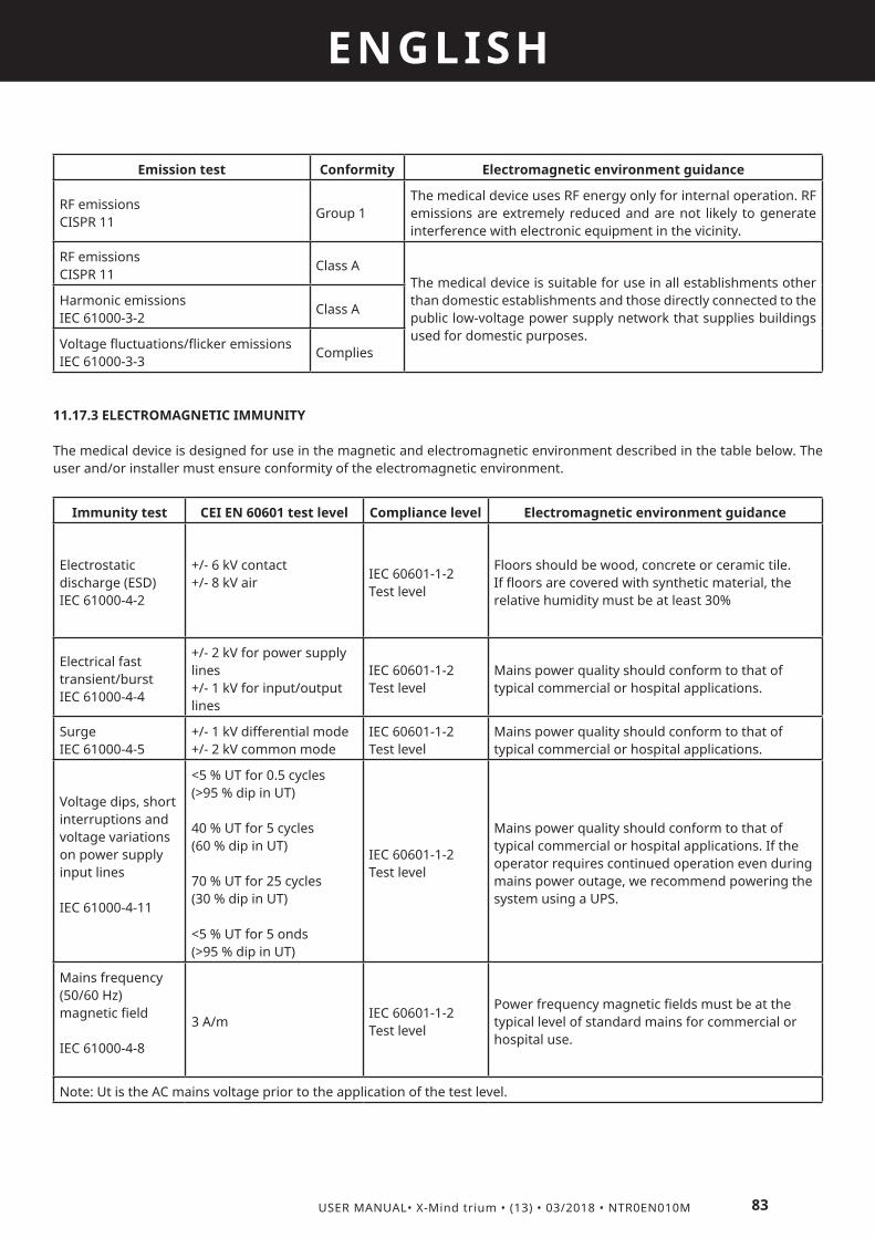
83
ENGLISH
USER MANUAL• X-Mind trium • (13) • 03/2018 • NTR0EN010M
Emission test Conformity Electromagnetic environment guidance
RF emissions CISPR 11
Group 1The medical device uses RF energy only for internal operation. RF emissions are extremely reduced and are not likely to generate interference with electronic equipment in the vicinity.
RF emissions CISPR 11
Class AThe medical device is suitable for use in all establishments other than domestic establishments and those directly connected to the public low-voltage power supply network that supplies buildings used for domestic purposes.
Harmonic emissions IEC 61000-3-2
Class A
Voltage fluctuations/flicker emissions IEC 61000-3-3
Complies
11.17.3 ELECTROMAGNETIC IMMUNITY
The medical device is designed for use in the magnetic and electromagnetic environment described in the table below. The user and/or installer must ensure conformity of the electromagnetic environment.
Immunity test CEI EN 60601 test level Compliance level Electromagnetic environment guidance
Electrostatic discharge (ESD)IEC 61000-4-2
+/- 6 kV contact+/- 8 kV air
IEC 60601-1-2Test level
Floors should be wood, concrete or ceramic tile. If floors are covered with synthetic material, the relative humidity must be at least 30%
Electrical fast transient/burstIEC 61000-4-4
+/- 2 kV for power supply lines+/- 1 kV for input/output lines
IEC 60601-1-2Test level
Mains power quality should conform to that of typical commercial or hospital applications.
SurgeIEC 61000-4-5
+/- 1 kV differential mode+/- 2 kV common mode
IEC 60601-1-2Test level
Mains power quality should conform to that of typical commercial or hospital applications.
Voltage dips, short interruptions and voltage variations on power supply input lines
IEC 61000-4-11
<5 % UT for 0.5 cycles(>95 % dip in UT)
40 % UT for 5 cycles(60 % dip in UT)
70 % UT for 25 cycles(30 % dip in UT)
<5 % UT for 5 onds(>95 % dip in UT)
IEC 60601-1-2Test level
Mains power quality should conform to that of typical commercial or hospital applications. If the operator requires continued operation even during mains power outage, we recommend powering the system using a UPS.
Mains frequency (50/60 Hz) magnetic field
IEC 61000-4-8
3 A/mIEC 60601-1-2Test level
Power frequency magnetic fields must be at the typical level of standard mains for commercial or hospital use.
Note: Ut is the AC mains voltage prior to the application of the test level.

84 USER MANUAL• X-Mind trium • (13) • 03/2018 • NTR0EN010M
ENGLISH
11.17.4 ELECTROMAGNETIC IMMUNITY, HANDHELD RADIOFREQUENCY EQUIPMENT
The medical device is designed for use in the magnetic and electromagnetic environment described in the table below. The user and/or installer must ensure conformity of the electromagnetic environment.
Immunity test CEI EN 60601 test level Compliance level Electromagnetic environment guidance
Handheld and mobile RF communication equipment must be used no closer to any part of the medical device, including cables than the recommended separation distance, calculated according to the equation corresponding to the frequency of the transmitter.
Conducted RFIEC 61000-4-6
3 Vrms150 kHz to 80 MHz
3 VrmsRecommended separation distanced = 1,2 √P
Radiated RFIEC 61000-4-3
10 V/m80MHz to 2.5GHz
3 V/m
d = 1,2 √P 80 MHz - 800 MHzd = 2,3 √P 800 MHz - 2.5 GHzWhere P is the maximum output power rating of the transmitter in watts (W)according to the transmitter manufacturer and “d” is the recommended separation distance in meters (m).
Field strength from fixed RF transmitters as determined by an electromagnetic site surveya must be below the compliance level corresponding to each frequency range.b
Interference can occur in the proximity of equipment marked with the following symbol:
Note 1: At 80 MHz and 800 MHz the higher frequency range applies.Note 2: These guidelines may not apply in every situation. Electromagnetic propagation is affected by absorption and reflection from structures, objects and people.(a) Field strength from fixed RF transmitters, such as base stations for radio (cellular/wireless) telephones and land mobile radios, amateur radio, AM and FM radio and TV broadcast cannot be predicted with accuracy on a theoretical basis. To assess the electromagnetic environment created by fixed RF transmitters, an electromagnetic site survey should be considered. If the measured field strength in the place where the equipment is used exceeds the corresponding RF compliance level (see above), it is important to ensure regular equipment operation. In the event of abnormal operation, additional measures may be required, such as redirecting or relocating the product.(b) Over the frequency range between 150 kHz and 80 MHz, the field strength must be below 10

12
85
ENGLISH
USER MANUAL• X-Mind trium • (13) • 03/2018 • NTR0EN010M
WARNINGS12.1 FEDERAL LAW
The indication below applies to the United States of America only.The United States Federal Law restricts the use of this medical device in its territory to qualified dental health professionals, fit and certified to perform and manage their professional duties.For the U.S. market: federal laws restrict these devices to sale by or on the order of a specialized surgeons, dentists and authorized personnel, who meet the requirements provided by the national laws in force in the country of installation.
12.2 WARNING APPLICABLE TO ALL COUNTRIES IN WHICH THE DEVICE IS SOLD
The information below is based on the requirements of standards to which the manufacturers of medical devices must adhere (as stated in the standard IEC 62366).
12.3 USER POPULATION
This radiological medical device must only be used by qualified dental health practitioners, fit and certified to perform their professional duties. The user must be authorised and duly trained (see Section 4.4 Specific user training), according to the requirements provided by the national laws in force in the country of installation. The training and preparation of personnel are included in the tasks of RESPONSIBLE ORGANIZATION.
Users must know and comply with the rules of dental practice in compliance with knowledge acquired in the field and the key medical hygiene principles including cleaning, disinfection and sterilization of medical devices.The medical device can be used by any adult dental practitioner of any weight, height, gender and nationality.The user must wear gloves.The user is not the patient.The user must not be prone to any of the following:• visual impairments: any vision problems must be corrected by glasses or lenses.• hearing difficulties that could prevent the user hearing audible alarms depending on medical devices;• difficulty memorizing or concentrating that could affect the setting of sequences or the performance of acquisition protocols.
12.4 SPECIFIC USER TRAINING
THE INDICATION BELOW APPLIES TO THE ONTARIO ONLY:The Standard of practice for CT dental scanners approved by Council – April 18, 2011 prescribes specific professional requirements for the use of CT dental scanners with respect to the FOV generated
INFORMATION APPLICABLE TO ALL THE COUNTRIES WHERE THE DEVICE IS SOLD:ACTEON Imaging, upon request, provides Training and/or materials for training on the basis of the specific needs identified by RESPONSIBLE ORGANIZATION.Contents, duration, options and details of the training courses are detailed in the purchasing contract, for information you must ask to your dealer / distributor.
12.5 PATIENT POPULATION
This medical device is designed to be used with the following patient population:• Children from 5 years old [~21 kg (46 lb); 113 cm (44.5 in) standing height],• Teenagers,• Adults,• Old Age Pensioners.This medical device can be used on any patient of any weight, age, height (except the restrictions indicated for children), gender and nationality.

86 USER MANUAL• X-Mind trium • (13) • 03/2018 • NTR0EN010M
ENGLISH
12.6 PATIENT POPULATION RESTRICTION
This medical device must not be used on the following patient population:• Infants,• pregnant women • Before exposing patients with pacemakers, contact the manufacturer of the latter to ensure that the X-rays generated by the medical device do not interfere with its functionalityThe user is the only person who can decide whether or not to make the radiologic acquisition with his/her patients.
12.7 PARTS OF THE BODY OR TYPES OF TISSUES FOR DIAGNOSIS
The medical device has been designed to acquire digital radiography images and reconstruct tomographic images of the dental maxillofacial and otolaryngological regions.
12.8 ESSENTIAL PERFORMANCE
ACTEON Imaging considered the essential performances, as stated in the applicable safety standard pertaining to the electrical medical device, in the Risk Management Process.
12.9 NORMAL USAGE CONDITIONS
The normal usage conditions are as follows:• Storage;• Installation;• Use;• Maintenance;• Disposal.
12.10 X-RAY PROTECTION
This symbol draws the ATTENTION to X-ray hazards: The medical device is a device that generates X-rays; therefore, both the patients and the operator are exposed to risks due to ionising radiation.
InstallationThe medical device must be shielded and used in compliance with the local standards in force and with the international directives concerning radiation protection for the operator, patient and other people against X-rays.
OperatorThe operator and other subjects must keep clear from the patient during the scan. The personnel involved in the radiographic examination must take all the safety measures concerning radiation protection.
PatientThe «General principles for safeguarding and protecting the personnel and patients» must always be applied during the use of the X-ray unit.• Justification of the practice• Optimisation of protection principle (ALARA principle)• Individual risk and dose limitsIt is the operator’s responsibility to protect the patient against unnecessary or excessive radiation doses.Additional protection devices (aprons, collars, etc.) are required to protect the patient from radiation.
12.11 MECHANICAL SAFETY
Improper installation of the medical device can expose the operator and patients to fall and crushing hazards. Prevent situations that can compromise the stability of the medical device, such as:

87
ENGLISH
USER MANUAL• X-Mind trium • (13) • 03/2018 • NTR0EN010M
• Changing its installation layout,• Moving the device,• Operate changes in the supporting wall structure.
12.12 ELECTRICAL SAFETY
The operator must not inspect internal parts or disassemble any part of the device and of the workstation.The unit must be installed solely in environments that meet safety standards and laws concerning premises used for medical purposes.
The unit is not equipped with protective devices against penetration of liquids; therefore it is essential to ensure that no water or other liquids can penetrate inside to prevent short circuits or corrosion.Always disconnect the system from the power supply and the workstation before cleaning and disinfecting it.Do not tread on the ETHERNET or on the CONTROL cable. Any damage to the conductors or connectors of these cables can compromise the proper operation of the device, its communication circuits and the Workstation.
The installation of the equipment must be permanent (fixed) in compliance with the IEC 60601-1 standard. It is PROHIBITED to plug the device to the power supply.
Don’t connect the device to the mains before ensuring the correct power supply voltage, as indicated in the identification plate. Incorrect voltage can cause irreversible damage to the electronic components of the medical device.The electrical system where the device is installed must be suitably earthed, in compliance with NEC and IEC standards and with the laws in force in the country of installation.
For Italy: The electrical system where the device is installed must be made in a workmanlike manner and in compliance with the IEC 64-8 standard with reference to premises used for medical purposes.
12.13 POSITIONING LASERS
X-MIND trium is a class 3R laser product. Avoid direct eye exposure to laser radiation. Viewing the laser output with telescopic optical instruments (for example, telescopes and binoculars) may pose an eye hazard and thus the user should not direct the beam into an area where such instruments are likely to be used
Use of controls or adjustments or performance of procedures other than those specified herein may result in hazardous radiation exposure
12.14 PATIENT DATA
Storage and Backups
The operator is responsible for the storage and backup of the data provided by the medical device. He should store all the clinical files and the patient database in a safe location, such as a server, NAS or CD/DVD and not on the Hard Disk of the medical workstation.Patient database and clinical files must be backed up periodically. The manufacturer shall not be held liable for damage due to data loss caused by failure to comply with these requirements and with the reference standards.Data protection
The operator is responsible for the protection of the patient data and the compliance to with the local standards in force. The operator must have appropriate security to prevent the patient data being accidentally or deliberately compromised.Security software like Firewall and Antivirus programs are necessary if the network environment of the workstation is connected to the Internet or have a connection with external data (USB key or portable HDD).The operator can contact Acteon Imaging Customer Service for information about encryption and password protection in the Acteon Imaging software.,

13
88 USER MANUAL• X-Mind trium • (13) • 03/2018 • NTR0EN010M
ENGLISH
INTERACTIONSCONTRAINDICATIONS
PROHIBITIONSThis includes information relating to the interactions, contraindications and prohibitions known by ACTEON Imaging® on the date on which this document was written.
13.1 INTERFERENCES WITH OTHER MEDICAL DEVICES
Interferences may occur when the system is used on patients fitted with a pacemaker.The medical device presents potential risks due to the emission of electromagnetic fields.
13.2 USING ACCESSORIES NOT SUPPLIED BY ACTEON IMAGING®
The medical device was designed and developed with its accessories to guarantee maximum safety and performance. The use of accessories from another source could put you and your patients at risk and could damage your medical device. Do not try to connect accessories not provided by ACTEON Imaging® to your medical device.Even if the manufacturer or dealer of your accessory claims full compatibility with ACTEON Imaging® equipment, it is advisable to exercise caution with regards to the origin and safety of the product offered. Look out in particular for lack of information, information in a foreign language, very attractive prices, suspect appearance, mediocre quality or premature wear. If necessary, contact an approved dealer or the ACTEON Imaging® Customer Service.
13.3 PROHIBITED USES
• Do not immerse or use outdoors.• Do not place the medical device next to a source of heat or in direct sunlight.• Do not expose the medical device to water spray or mist.A hot/cold temperature contrast can cause condensation to form in the medical device, which may be dangerous. The medical device may not be stored or used outside the atmospheric pressure and temperature ranges recommended in the User Manual supplied with your medical device.Do not touch accessible electrical connections.
13.4 MOVING THE MEDICAL DEVICE
After its initial installation, the medical device is not designed to be moved. The medical device must be fixed to ensure that it cannot be removed or moved without the use of a tool. Do not move the medical device during use.
13.5 ASSEMBLY AND DISASSEMBLY
Unless otherwise indicated in the instructions specific to your medical device:• Control devices are not designed to be removed or disassembled.• Access doors and/or flaps are not designed to be removed or disassembled.

2460
de Götzen S.r.l • A company of ACTEON Group Via Roma 45 • 21057 OLGIATE OLONA (VARESE) • ITALY
Tel +39 0331 376 762 • Fax +39 0331 376 763 E-mail: [email protected] •www.acteongroup.com