user manual cyclone g4 - tempest.biztempest.biz/admin/media/files/projectorenclosures... ·...
TRANSCRIPT
Cyclone G4 User Manual 1
User Manual Cyclone G4
Revision 01.7 May 2018
© Tempest Lighting, Inc.
Cyclone G4 User Manual 2
Table of Contents Table of Contents ........................................................................................................................................................................................ 2
Approvals – North America .................................................................................................................................................................... 5
Approvals – Europe ................................................................................................................................................................................ 6
Approvals – China ................................................................................................................................................................................... 7
Introduction ................................................................................................................................................................................................ 8
IMPORTANT: Safety Advisories .............................................................................................................................................................. 8
Installation ................................................................................................................................................................................................... 9
Dimensions, Rigging Points, and Maximum Projector Dimensions/Power ......................................................................................... 9
Access Clearance .............................................................................................................................................................................. 10
Airflow Clearance ............................................................................................................................................................................. 10
Snow Clearance ................................................................................................................................................................................ 10
Mounting Hardware Options ............................................................................................................................................................... 11
Mounting Bolts ................................................................................................................................................................................. 11
Mounting Options – Unistrut Kit ..................................................................................................................................................... 11
Mounting Options – Stacking Kit ..................................................................................................................................................... 12
Mounting Options – Swivel Stacking Kit .......................................................................................................................................... 12
Cyclovator 2 Tilt Kit ............................................................................................................................................................................... 13
SAFETY WARNING ............................................................................................................................................................................. 13
Cyclovator – Unistrut Mounting Rails .............................................................................................................................................. 13
Cyclovator – Inlet Cowl .................................................................................................................................................................... 13
Fixing the Cyclovator in Place .......................................................................................................................................................... 14
Mounting the Enclosure ................................................................................................................................................................... 15
Setting the Show Position Stop ........................................................................................................................................................ 16
Wiring the Enclosure ................................................................................................................................................................................ 17
Power Wiring ........................................................................................................................................................................................ 17
SAFETY NOTICE ................................................................................................................................................................................. 17
Electrical Standards .......................................................................................................................................................................... 17
Wiring Access .................................................................................................................................................................................... 18
One or Two Power Circuits? ............................................................................................................................................................ 19
Single Feed Power Termination ....................................................................................................................................................... 20
Split Feed Power Termination ......................................................................................................................................................... 20
AC Supply Voltage............................................................................................................................................................................. 20
North America, 208V Single Feed .................................................................................................................................................... 21
North America, 208V Split Feed ...................................................................................................................................................... 22
International, 230V Single Feed ....................................................................................................................................................... 23
International, 230V Split Feed ......................................................................................................................................................... 24
Cyclone G4 User Manual 3
Remote Monitoring Connections ........................................................................................................................................................ 25
RS485 (DMX/RDM) Cable Terminations .......................................................................................................................................... 26
Line Termination Switch Settings .................................................................................................................................................... 27
Projector Power Control using DMX512 ......................................................................................................................................... 28
DMX/RDM Network, using JESE RDM-TRI ....................................................................................................................................... 29
Positive Pressure Fan Control Option .................................................................................................................................................. 30
Digital Enclosure Control .......................................................................................................................................................................... 31
Schematic .............................................................................................................................................................................................. 31
DEC4 Main Functions ........................................................................................................................................................................... 32
Firmware Revision ............................................................................................................................................................................ 32
Factory Settings – Data Modes ............................................................................................................................................................ 32
Hardware Indicators & Fuses ............................................................................................................................................................... 33
............................................................................................................................................................................................................... 33
Operating Modes .................................................................................................................................................................................. 34
RDM Only Monitor (Factory Default) .............................................................................................................................................. 34
RDM+DMX Control ........................................................................................................................................................................... 34
RDM+DMX Service ........................................................................................................................................................................... 34
DEC4 Control Parameters .................................................................................................................................................................... 35
Control Interface .............................................................................................................................................................................. 36
User Interface LCD Display ............................................................................................................................................................... 37
Control Interface Operation ............................................................................................................................................................ 37
Control Menu ........................................................................................................................................................................................ 38
Set Data Options ............................................................................................................................................................................... 38
Set Temp Units ................................................................................................................................................................................. 39
Set Temp Ranges .............................................................................................................................................................................. 39
Set Max Humidity ............................................................................................................................................................................. 39
Set Lamp On Point ............................................................................................................................................................................ 39
Reset Lamp Hours............................................................................................................................................................................. 40
Set Fan Function ............................................................................................................................................................................... 40
Status Display .................................................................................................................................................................................... 40
DEC4 Firmware Updates .......................................................................................................................................................................... 41
Indirect Firmware Updates .................................................................................................................................................................. 41
Requirements ................................................................................................................................................................................... 41
Installation Procedure ...................................................................................................................................................................... 41
Mounting the Projector ............................................................................................................................................................................ 46
Important: Check Lamp-on Current ..................................................................................................................................................... 46
Enclosure Configuration ....................................................................................................................................................................... 46
Landscape Configurations ................................................................................................................................................................ 46
Cyclone G4 User Manual 4
Portrait Configurations ..................................................................................................................................................................... 47
Projector-specific Mounting ................................................................................................................................................................ 47
Mount the Projector – Tabletop ...................................................................................................................................................... 47
Mount the Projector – Ceiling ......................................................................................................................................................... 47
Mount the Projector – Portrait ........................................................................................................................................................ 48
Connect Projector and Aux Equipment ........................................................................................................................................... 48
Projector-specific Mounting ................................................................................................................................................................ 49
Christie J-Series/Roadster Family .................................................................................................................................................... 49
Barco HDX ......................................................................................................................................................................................... 49
DPI Insight 4K .................................................................................................................................................................................... 50
Barco HDQ ........................................................................................................................................................................................ 51
Routine Maintenance ............................................................................................................................................................................... 52
Clean Port Glass ................................................................................................................................................................................ 52
Check Filter ....................................................................................................................................................................................... 52
Check Temperature/Humidity Sensor ............................................................................................................................................. 53
For After Sales Support .................................................................................................................................................................... 53
Troubleshooting ........................................................................................................................................................................................ 54
Warranty ................................................................................................................................................................................................... 56
Appendix – TEMP Protocol ....................................................................................................................................................................... 57
Physical Layer ........................................................................................................................................................................................ 57
Developer’s Guide ................................................................................................................................................................................ 57

Cyclone G4 User Manual 5
Approvals – North America
This is to certify that the following products:
55.xxx.US Series Cyclone G4 Projector Enclosures
Have been tested and approved to standards UL 508 (electrical) and UL 50 (environmental), as NEMA 3R enclosures, for use in the United States and Canada.
This declaration is made by the manufacturer
Tempest Lighting, Inc.
11845 Wicks Street, Sun Valley, CA 91352, USA
This declaration is based on tests that were conducted on the submitted samples of the above mentioned products.
Listing Report No. 3198609LAX-001a refers.
Dated: July 1st , 2016
Signature . . . . . . . . . . . . . .
Tempest Lighting Inc

Cyclone G4 User Manual 6
Approvals – Europe
CERTIFICATE AND DECLARATION OF CONFORMITY
FOR CE MARKING
Tempest Lighting, Inc.
11845 Wicks Street, Sun Valley, CA 91352, USA
t: +1 818 787 8984 f: +1 818 252 7101 e: [email protected]
www.tempest.biz
Tempest Lighting, Inc. declares that t heir
Cyclone G4 Projector Enclosure Series 55.xxx.xx
complies with the Essential Requirements of the following EU Directives:
Low Voltage Directive 2006/95/EC Test Report G4.51.LVD
Electromagnetic Compatibility Directive 2004/108/EC Test Report G4.51.EMC
and further conforms with the following EU Harmonized Standards:
EN 60065 : 2002 Test Report 60065.G4.51.01 EN 60529:2001-2002 Test Report 60529.G4.51.02 EN 61000-6-3:2007+A1:2011 Test Report 61000.G4.51.03 EN61000-6-1:2007 Test Report 61000.G4.51.03 EN55015:2006+A2:2009 Test Report 61000.G4.51.03
Dated: 1s t July 2016
Position of signatory: President
Name of Signatory: Tim Burnham
Signed below:
on behalf of Tempest Lighting, Inc.
. . . . . . . . . . . . . . . . . . . . . . . . . . . . .
Cyclone G4 User Manual 7
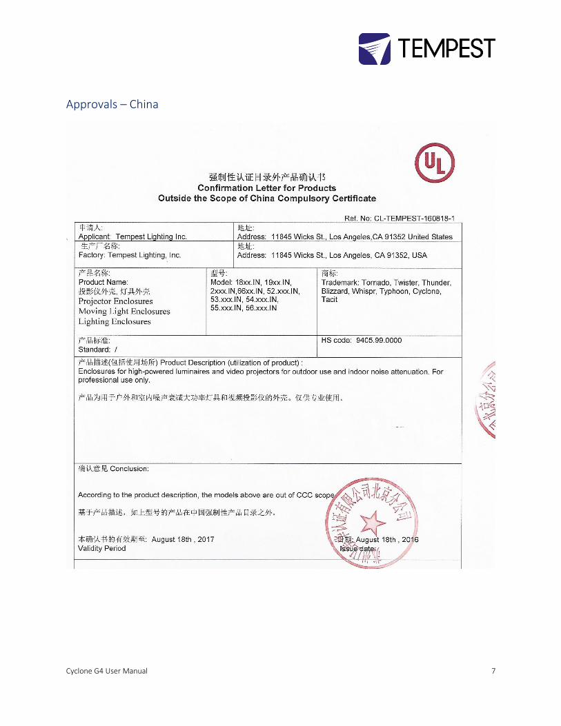
Approvals – China

Cyclone G4 User Manual 8
Introduction Thank you for purchasing a Tempest enclosure! We have worked hard to provide you with the very best product available for its purpose, and we shall continue to do everything possible to ensure that it works well for you for many years to come.
Please read this manual before starting work!
In the event of difficulty, please contact your Tempest reseller or Tempest direct:
+1 818 787 8984
We will do everything we can to help you get the very best results from your Tempest enclosure.
IMPORTANT: Safety Advisories
• All installation and rigging work done must where applicable be designed and built in accordance with norms and standards of the local authority having jurisdiction of the installation site. It is the responsibility of the installer to obtain such approvals as may be required to achieve full compliance.
• All electrical work must be carried out by a suitably licensed electrical contractor in full compliance with local electrical standards.
• Lifting: some enclosures and the equipment inside them may be heavy. Use properly rated lifting equipment where appropriate and never attempt to carry out work with fewer than the number of workers needed to lift safely.
• It is the responsibility of the installer to ensure that all local building, safety and electrical codes are strictly adhered to in the installation of this enclosure. Tempest Lighting, Inc., its employees and agents are in no way responsible for damage arising from failure to follow either the instructions in this manual or building, safety and electrical codes prevailing at the installation location.
• Do not attempt to install or operate the enclosure before fully reading and understanding this manual
• Never allow anyone who has not read this manual to open the enclosure or perform maintenance on the projector within.
• Never leave the enclosure unattended when open.
• Always make sure all bolts and latches are tight and safety locks are in place after performing any form of maintenance on the unit.
• Do not open any electrical boxes until power has been shut off to all supply lines to the enclosure (including the one powering the projector).
• Do not open the enclosure in wet weather.
Cyclone G4 User Manual 9
Installation
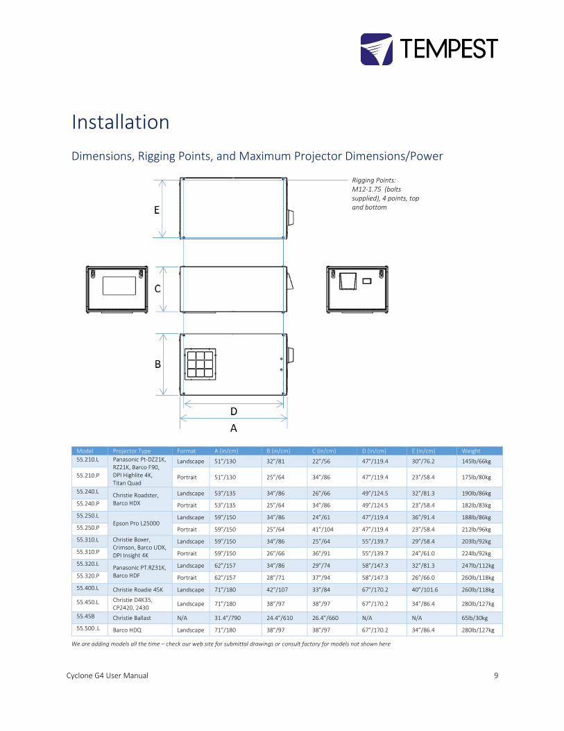
Dimensions, Rigging Points, and Maximum Projector Dimensions/Power
Model Projector Type Format A (in/cm) B (in/cm) C (in/cm) D (in/cm) E (in/cm) Weight
55.210.L Panasonic Pt-DZ21K, RZ21K, Barco F90, DPI Highlite 4K, Titan Quad
Landscape 51”/130 32”/81 22”/56 47”/119.4 30”/76.2 145lb/66kg
55.210.P Portrait 51”/130 25”/64 34”/86 47”/119.4 23”/58.4 175lb/80kg
55.240.L Christie Roadster, Barco HDX
Landscape 53”/135 34”/86 26”/66 49”/124.5 32”/81.3 190lb/86kg
55.240.P Portrait 53”/135 25”/64 34”/86 49”/124.5 23”/58.4 182lb/83kg
55.250.L Epson Pro L25000
Landscape 59”/150 34”/86 24”/61 47”/119.4 36”/91.4 188lb/86kg
55.250.P Portrait 59”/150 25”/64 41”/104 47”/119.4 23”/58.4 212lb/96kg
55.310.L Christie Boxer, Crimson, Barco UDX, DPI Insight 4K
Landscape 59”/150 34”/86 25”/64 55”/139.7 29”/58.4 203lb/92kg
55.310.P Portrait 59”/150 26”/66 36”/91 55”/139.7 24”/61.0 224lb/92kg
55.320.L Panasonic PT.RZ31K, Barco HDF
Landscape 62”/157 34”/86 29”/74 58”/147.3 32”/81.3 247lb/112kg
55.320.P Portrait 62”/157 28”/71 37”/94 58”/147.3 26”/66.0 260lb/118kg
55.400.L Christie Roadie 45K Landscape 71”/180 42”/107 33”/84 67”/170.2 40”/101.6 260lb/118kg
55.450.L Christie D4K35, CP2420, 2430
Landscape 71”/180 38”/97 38”/97 67”/170.2 34”/86.4 280lb/127kg
55.45B Christie Ballast N/A 31.4”/790 24.4”/610 26.4”/660 N/A N/A 65lb/30kg
55.500 .L Barco HDQ Landscape 71”/180 38”/97 38”/97 67”/170.2 34”/86.4 280lb/127kg
We are adding models all the time – check our web site for submittal drawings or consult factory for models not shown here
Rigging Points: M12-1.75 (bolts supplied), 4 points, top and bottom
Cyclone G4 User Manual 10
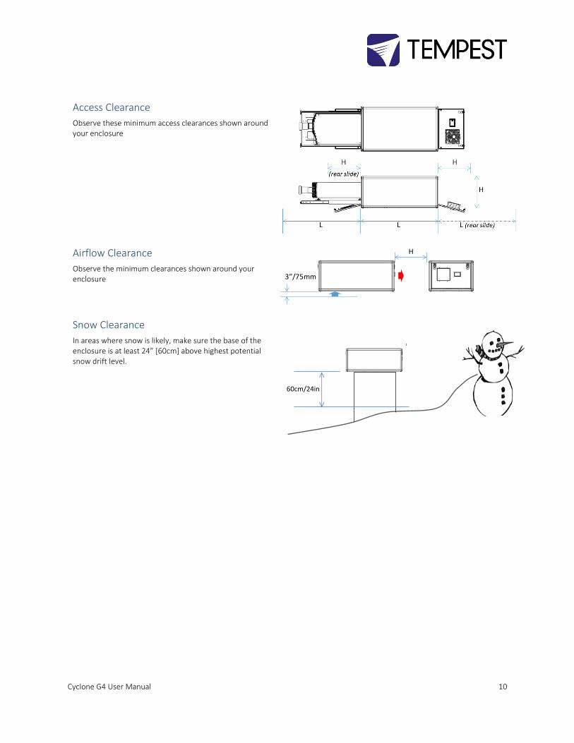
Access Clearance
Observe these minimum access clearances shown around your enclosure
Airflow Clearance
Observe the minimum clearances shown around your enclosure
Snow Clearance
In areas where snow is likely, make sure the base of the enclosure is at least 24” [60cm] above highest potential snow drift level.
H
3”/75mm
60cm/24in
Cyclone G4 User Manual 11
Mounting Hardware Options
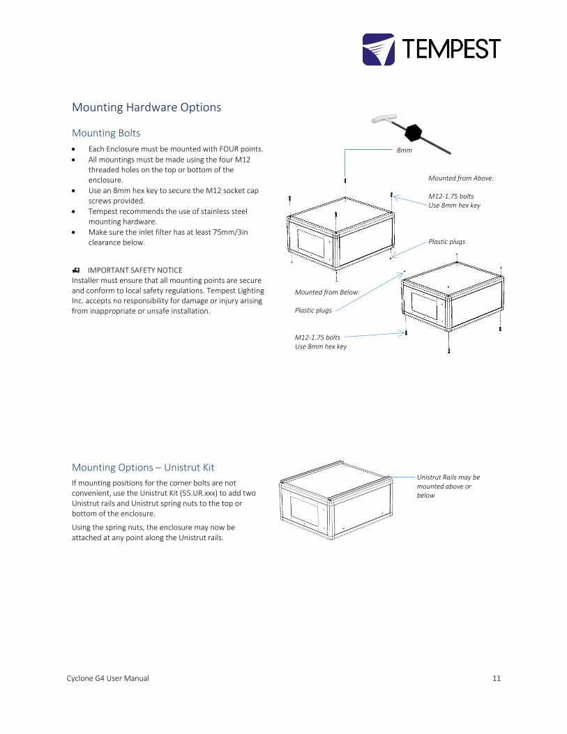
Mounting Bolts
• Each Enclosure must be mounted with FOUR points.
• All mountings must be made using the four M12 threaded holes on the top or bottom of the enclosure.
• Use an 8mm hex key to secure the M12 socket cap screws provided.
• Tempest recommends the use of stainless steel mounting hardware.
• Make sure the inlet filter has at least 75mm/3in clearance below.
IMPORTANT SAFETY NOTICE Installer must ensure that all mounting points are secure and conform to local safety regulations. Tempest Lighting Inc. accepts no responsibility for damage or injury arising from inappropriate or unsafe installation.
Mounting Options – Unistrut Kit
If mounting positions for the corner bolts are not convenient, use the Unistrut Kit (55.UR.xxx) to add two Unistrut rails and Unistrut spring nuts to the top or bottom of the enclosure.
Using the spring nuts, the enclosure may now be attached at any point along the Unistrut rails.
8mm
Mounted from Above: M12-1.75 bolts Use 8mm hex key Plastic plugs
Mounted from Below: Plastic plugs M12-1.75 bolts Use 8mm hex key
Unistrut Rails may be mounted above or below
Cyclone G4 User Manual 12
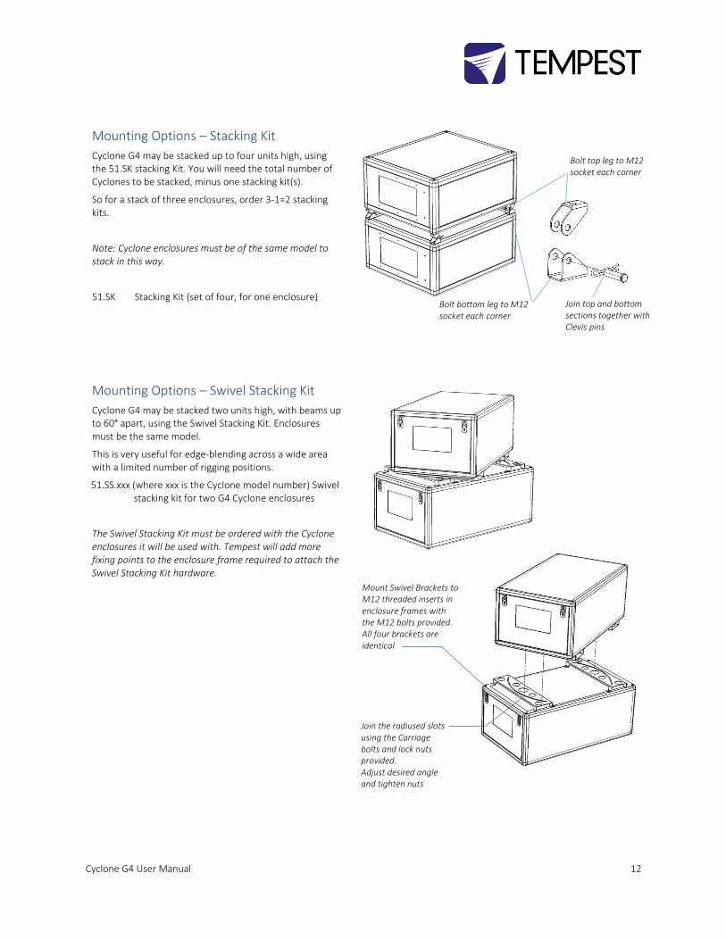
Mounting Options – Stacking Kit
Cyclone G4 may be stacked up to four units high, using the 51.SK stacking Kit. You will need the total number of Cyclones to be stacked, minus one stacking kit(s).
So for a stack of three enclosures, order 3-1=2 stacking kits.
Note: Cyclone enclosures must be of the same model to stack in this way.
51.SK Stacking Kit (set of four, for one enclosure)
Mounting Options – Swivel Stacking Kit
Cyclone G4 may be stacked two units high, with beams up to 60° apart, using the Swivel Stacking Kit. Enclosures must be the same model.
This is very useful for edge-blending across a wide area with a limited number of rigging positions.
51.SS.xxx (where xxx is the Cyclone model number) Swivel stacking kit for two G4 Cyclone enclosures
The Swivel Stacking Kit must be ordered with the Cyclone enclosures it will be used with. Tempest will add more fixing points to the enclosure frame required to attach the Swivel Stacking Kit hardware.
Bolt top leg to M12 socket each corner
Bolt bottom leg to M12 socket each corner
Join top and bottom sections together with Clevis pins
Mount Swivel Brackets to M12 threaded inserts in enclosure frames with the M12 bolts provided. All four brackets are identical
Join the radiused slots using the Carriage bolts and lock nuts provided. Adjust desired angle and tighten nuts

Cyclone G4 User Manual 13
Cyclovator 2 Tilt Kit
SAFETY WARNING
IT IS A SAFETY REQUIREMENT that Cyclone enclosures be horizontal any time you slide the projector out for service. IT IS DANGEROUS to do this if the enclosure is not horizontal, and MAY CAUSE DAMAGE TO THE PROJECTOR OR INFLICT SERIOUS INJURY TO PERSONNEL. Tempest Lighting Inc., its agents and employees, will not be liable for consequences of failure to heed this safety warning.
Cyclovator 2 may be used for any G3 or G4 Cyclone enclosure.
The enclosure may be installed at ground level, projecting up (up onto a building, for example)…
…or, on a rooftop, projecting downwards.
In either case, the maximum tilt angle is 60°.
Cyclovator – Unistrut Mounting Rails
When Cyclone G4 is used with the Cyclovator Tilt Kit, the Unistrut Kit (55.UR.xxx) is required to attach the enclosure to the Cyclovator.
‘xxx’ is the Cyclone model number.
Cyclovator – Inlet Cowl
When Cyclone G4 is used with the Cyclovator Tilt Kit, with a tilt angle greater than 40°, use the inlet cowl 55.IC.xx to protect the inlet filter from weather.
‘xx’ is the filter size in inches – 15 for 55.200-350, 22 for 55.400 and up.
Stainless Steel Unistrut Rail Kit 55.UR.xxx Inlet Cowl 55.IC.xx
Cyclone G4 User Manual 14
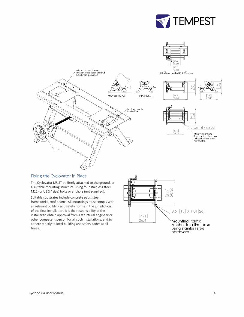
Fixing the Cyclovator in Place
The Cyclovator MUST be firmly attached to the ground, or a suitable mounting structure, using four stainless steel M12 (or US ½” size) bolts or anchors (not supplied).
Suitable substrates include concrete pads, steel frameworks, roof beams. All mountings must comply with all relevant building and safety norms in the jurisdiction of the final installation. It is the responsibility of the installer to obtain approval from a structural engineer or other competent person for all such installations, and to adhere strictly to local building and safety codes at all times.
Cyclone G4 User Manual 15
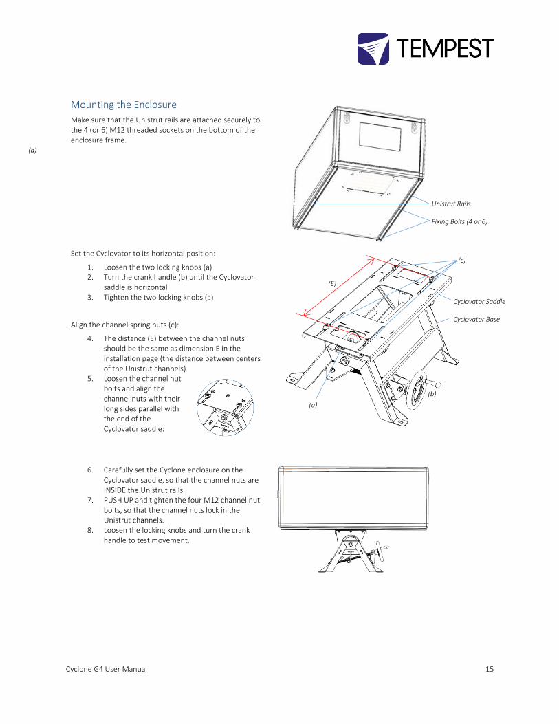
Mounting the Enclosure
Make sure that the Unistrut rails are attached securely to the 4 (or 6) M12 threaded sockets on the bottom of the enclosure frame.
Set the Cyclovator to its horizontal position:
1. Loosen the two locking knobs (a) 2. Turn the crank handle (b) until the Cyclovator
saddle is horizontal 3. Tighten the two locking knobs (a)
Align the channel spring nuts (c):
4. The distance (E) between the channel nuts should be the same as dimension E in the installation page (the distance between centers of the Unistrut channels)
5. Loosen the channel nut bolts and align the channel nuts with their long sides parallel with the end of the Cyclovator saddle:
6. Carefully set the Cyclone enclosure on the Cyclovator saddle, so that the channel nuts are INSIDE the Unistrut rails.
7. PUSH UP and tighten the four M12 channel nut bolts, so that the channel nuts lock in the Unistrut channels.
8. Loosen the locking knobs and turn the crank handle to test movement.
Unistrut Rails Fixing Bolts (4 or 6)
(a)
(b) (a)
(c)
(E)
Cyclovator Saddle Cyclovator Base
Cyclone G4 User Manual 16
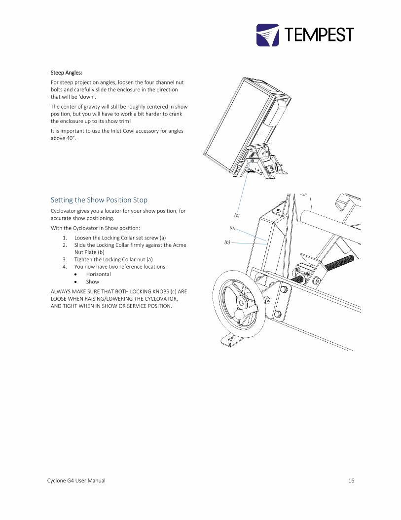
Steep Angles:
For steep projection angles, loosen the four channel nut bolts and carefully slide the enclosure in the direction that will be ‘down’.
The center of gravity will still be roughly centered in show position, but you will have to work a bit harder to crank the enclosure up to its show trim!
It is important to use the Inlet Cowl accessory for angles above 40°.
Setting the Show Position Stop
Cyclovator gives you a locator for your show position, for accurate show positioning.
With the Cyclovator in Show position:
1. Loosen the Locking Collar set screw (a) 2. Slide the Locking Collar firmly against the Acme
Nut Plate (b) 3. Tighten the Locking Collar nut (a) 4. You now have two reference locations:
• Horizontal
• Show
ALWAYS MAKE SURE THAT BOTH LOCKING KNOBS (c) ARE LOOSE WHEN RAISING/LOWERING THE CYCLOVATOR, AND TIGHT WHEN IN SHOW OR SERVICE POSITION.
(a)
(b)
(c)
Cyclone G4 User Manual 17
Wiring the Enclosure
Power Wiring
SAFETY NOTICE
All power wiring must be performed by a competent electrician, appropriately licensed in the jurisdiction where the installation takes place. All electrical work must be done in full compliance with all electrical and safety norms applicable to the installation site. Isolate all power feeds before opening the enclosure.
Tempest Lighting, Inc., its employees and agents will not be held responsible for damage or injury caused by disregarding this notice.
Electrical Standards
Important:
Enclosure model numbers including .US are for use in countries using US and Japanese style electrical systems:
200-208VAC 50/60Hz
Enclosure model numbers including .IN are for use in countries using European style electrical systems:
220-250VAC 50/60Hz
Note:
(1) Fans and Heaters are rated 200-250V (2) Electronics are autosensing for any voltage 90-265VAC, 50/60Hz
Cyclone G4 User Manual 18
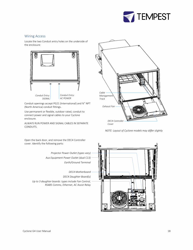
Wiring Access
Locate the two Conduit entry holes on the underside of the enclosure:
Conduit openings accept PG21 (International) and ¾” NPT (North America) conduit fittings.
Use permanent or flexible, outdoor rated, conduit to connect power and signal cables to your Cyclone enclosure.
ALWAYS RUN POWER AND SIGNAL CABLES IN SEPARATE CONDUITS.
NOTE: Layout of Cyclone models may differ slightly
Open the back door, and remove the DEC4 Controller cover. Identify the following parts:
Projector Power Outlet (types vary)
Aux Equipment Power Outlet (dual C13)
Earth/Ground Terminal
DEC4 Motherboard
DEC4 Daughter Board(s)
Up to 3 daughter boards: types include Fan Control, RS485 Comms, Ethernet, AC Assist Relay
DEC4 Controller Cover
Exhaust Fan
Cable Management Track
Conduit Entry: SIGNAL
Conduit Entry: AC POWER
Cyclone G4 User Manual 19
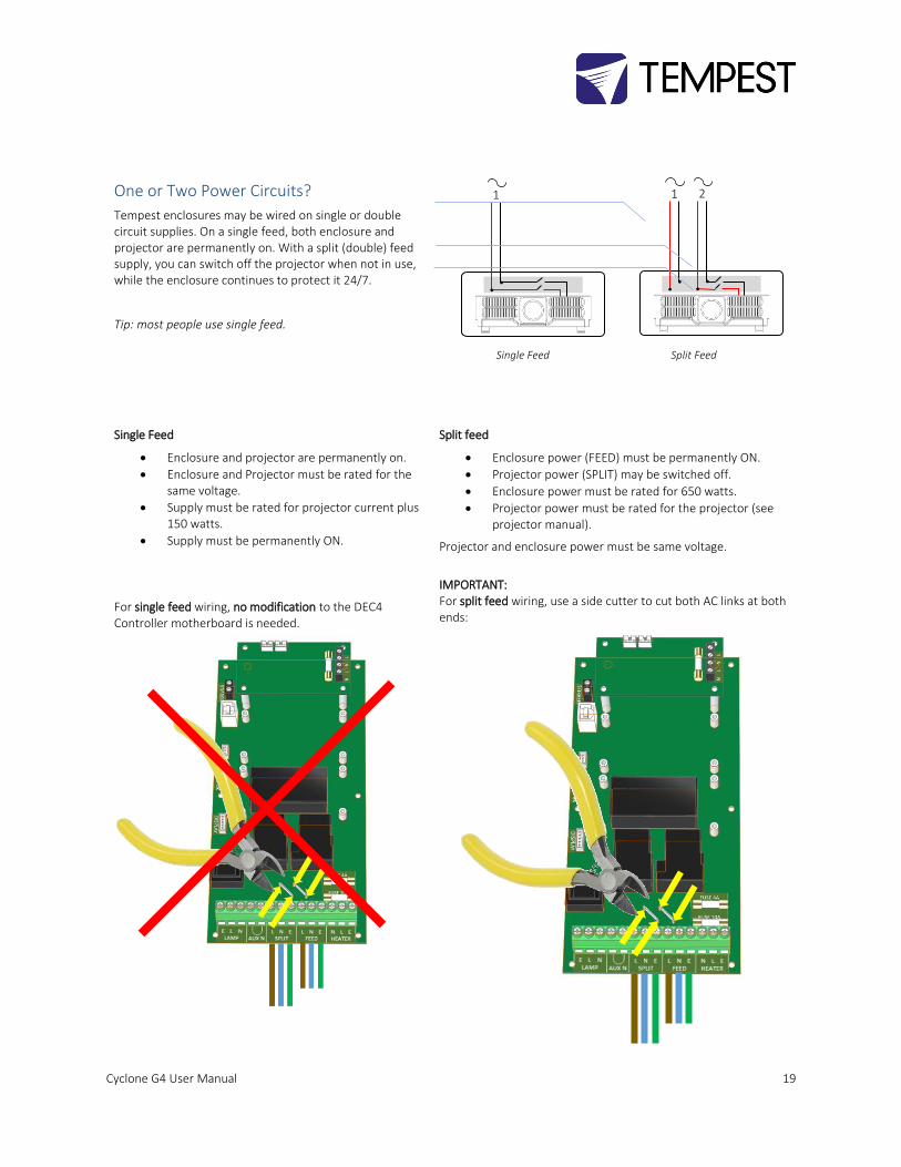
One or Two Power Circuits?
Tempest enclosures may be wired on single or double circuit supplies. On a single feed, both enclosure and projector are permanently on. With a split (double) feed supply, you can switch off the projector when not in use, while the enclosure continues to protect it 24/7.
Tip: most people use single feed.
Single Feed
• Enclosure and projector are permanently on.
• Enclosure and Projector must be rated for the same voltage.
• Supply must be rated for projector current plus 150 watts.
• Supply must be permanently ON.
Split feed
• Enclosure power (FEED) must be permanently ON.
• Projector power (SPLIT) may be switched off.
• Enclosure power must be rated for 650 watts.
• Projector power must be rated for the projector (see projector manual).
Projector and enclosure power must be same voltage.
For single feed wiring, no modification to the DEC4 Controller motherboard is needed.
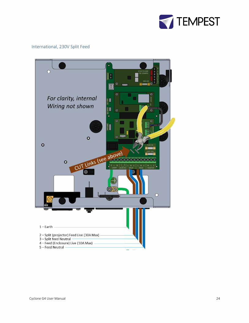
IMPORTANT: For split feed wiring, use a side cutter to cut both AC links at both ends:
1 1 2
Single Feed
Split Feed
Cyclone G4 User Manual 20
Single Feed Power Termination
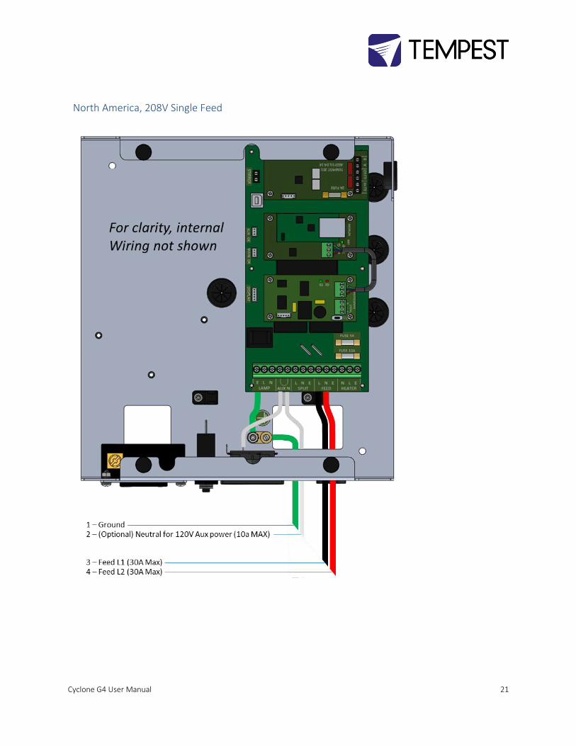
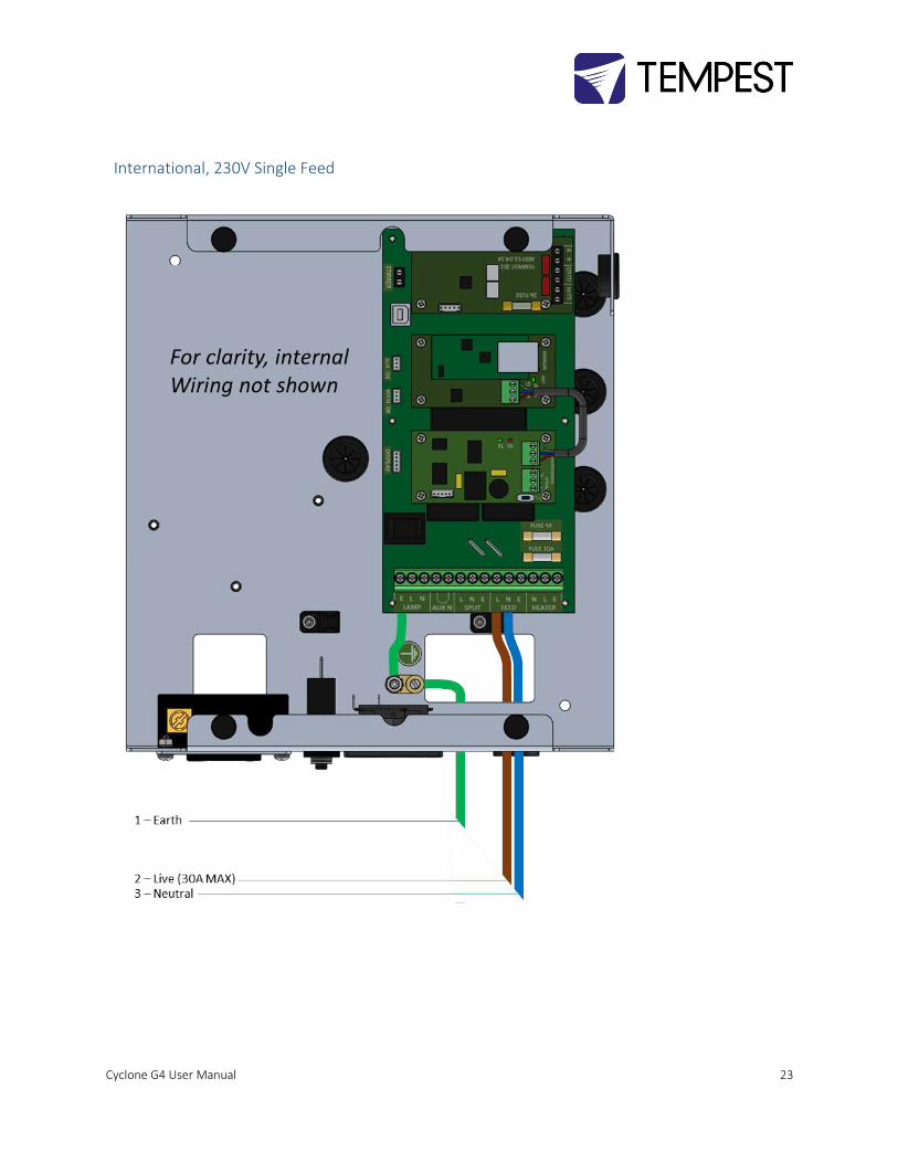
• Connect Earth/Ground wire to Ground Terminal
• Connect Live and Neutral to the terminals marked FEED
SEE DIAGRAMS ON FOLLOWING PAGES
Split Feed Power Termination
• STOP! Did you cut the power links? See above.
• Connect Earth/Ground wire to Ground Terminal
• Connect Enclosure feed to the terminals marked FEED
• Connect Projector feed to the terminals marked SPLIT
SEE DIAGRAMS ON FOLLOWING PAGES
AC Supply Voltage
Tempest Cyclone enclosures require supply voltage in the nominal range 200-250VAC, 50/60Hz.
Tempest G4 enclosures are very tolerant of supply voltage variations:
• DEC4 controller has a universal power supply and operates on 90-265VAC
• Enclosure fans and heaters are rated 200-250VAC. Fans are over-dimensioned to cool adequately down to 200V, and heaters compensate thermostatically by increasing duty cycle on lower supply voltages.
Cyclone G4 User Manual 21
North America, 208V Single Feed

Cyclone G4 User Manual 22
North America, 208V Split Feed
Cyclone G4 User Manual 23
International, 230V Single Feed
Cyclone G4 User Manual 24
International, 230V Split Feed

Cyclone G4 User Manual 25
Remote Monitoring Connections
Tempest G4 enclosures optionally support three types of remote monitoring:
1. Direct via Ethernet, using Tempest TEMP protocol (see Appendix – TEMP Protocol)
Requires 51.EN Ethernet board
2. Grouped via RS485, using an Ethernet bridge and Tempest TEMP protocol (see Appendix – TEMP Protocol)
3. Grouped via RS485, using DMX/RDM – see next page
Requires one 51.485 RS485 board per enclosure
Requires one 51.485 RS485 board per enclosure and one 51.EN Ethernet board per bridge
Note: Consult factory for Tempest System Manager and web-based monitoring availability
Cyclone G4 User Manual 26
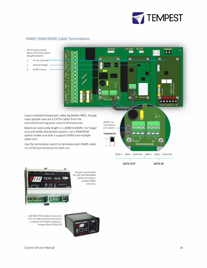
RS485 (DMX/RDM) Cable Terminations
Loop a shielded twisted pair cable (eg Belden 9841, though many people now use a CAT5e cable) from the control/monitoring point, around all enclosures.
Maximum total cable length is 1,200M (4,000ft). For longer runs and wildly distributed systems, use a DMX/RDM splitter (make sure that it supports RDM) and multiple cable runs.
Use the termination switch to terminate each RS485 cable run at the last enclosure on each run.
RS485 Line Termination (LT) Switch: TERMINATED
Data + Data - Common Data + Data - Common
DATA OUT DATA IN
DEC4 System Control Board, with three typical Daughter Boards:
1. AC Fan Controller
2. Ethernet Bridge
3. RS485 Comms
JESE RDM-TRI interface connects to a PC via USB to monitor and control
a network of Tempest enclosures. Tempest Item # 2000.195
Tempest recommends the JESE SH8 DMX/RDM
Splitter for large or complex RS485
networks.
Cyclone G4 User Manual 27
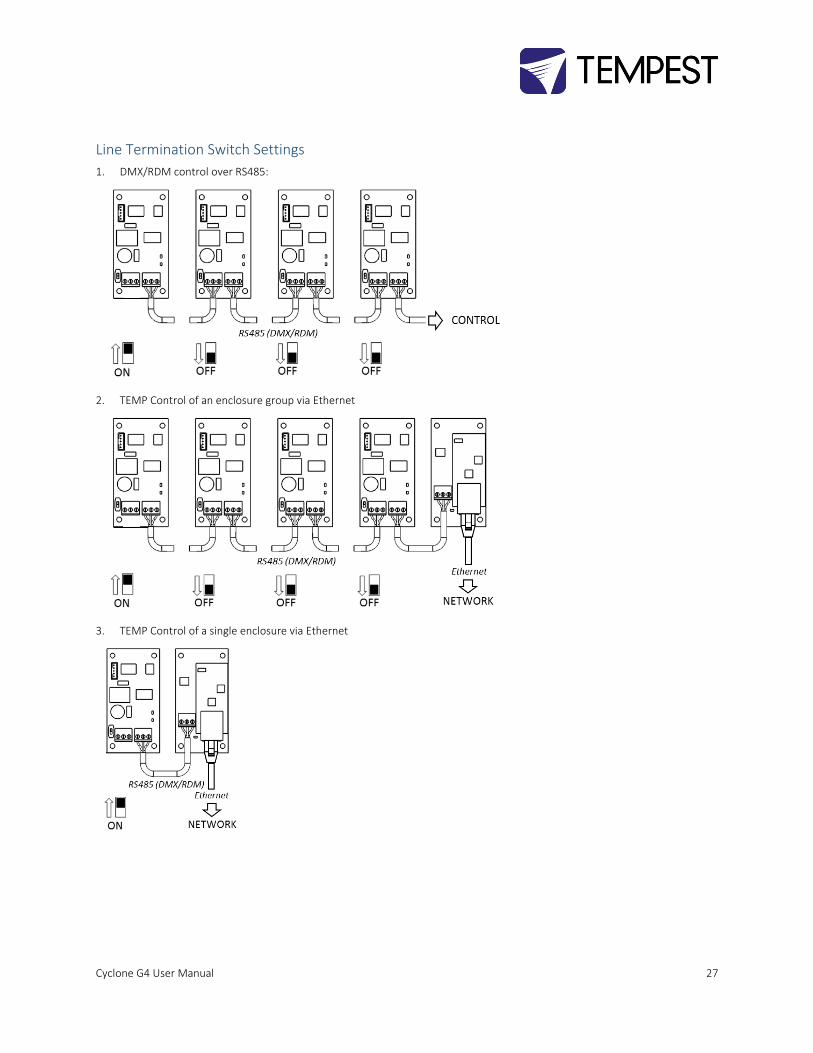
Line Termination Switch Settings
1. DMX/RDM control over RS485:
2. TEMP Control of an enclosure group via Ethernet
3. TEMP Control of a single enclosure via Ethernet
Cyclone G4 User Manual 28
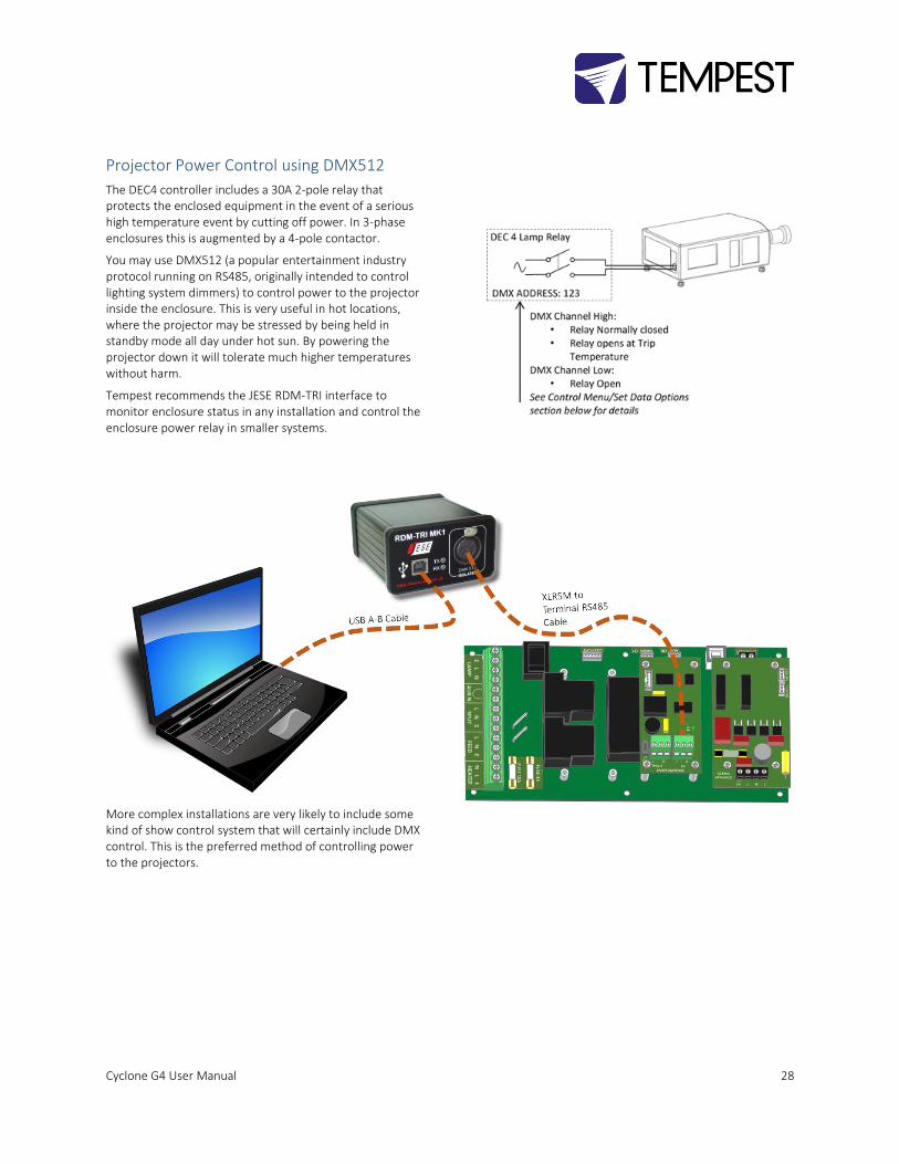
Projector Power Control using DMX512
The DEC4 controller includes a 30A 2-pole relay that protects the enclosed equipment in the event of a serious high temperature event by cutting off power. In 3-phase enclosures this is augmented by a 4-pole contactor.
You may use DMX512 (a popular entertainment industry protocol running on RS485, originally intended to control lighting system dimmers) to control power to the projector inside the enclosure. This is very useful in hot locations, where the projector may be stressed by being held in standby mode all day under hot sun. By powering the projector down it will tolerate much higher temperatures without harm.
Tempest recommends the JESE RDM-TRI interface to monitor enclosure status in any installation and control the enclosure power relay in smaller systems.
More complex installations are very likely to include some kind of show control system that will certainly include DMX control. This is the preferred method of controlling power to the projectors.
Cyclone G4 User Manual 29
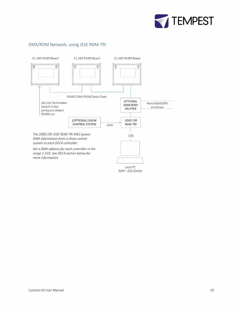
DMX/RDM Network, using JESE RDM-TRI
The 2000.195 JESE RDM-TRI MK2 passes DMX information from a show control system to each DEC4 controller.
Set a DMX address for each controller in the range 1-510. See DEC4 section below for more information.

Cyclone G4 User Manual 30
Positive Pressure Fan Control Option
When the Positive Pressure (51.PP) option is ordered, the enclosure fan function is changed.
• Normally the enclosure fan(s) will run only when either the projector/luminaire lamp is on, or if the daytime temperature in the enclosure exceeds the DEC Upper Temperature setting. At all other times the fan is OFF.
• With the Positive Pressure option, when the fan would normally be off, it is instead powered via a capacitor that lowers the operating voltage so that the fan continues to run at a low level, maintaining positive pressure in the enclosure and preventing harmful contaminants from entering through the exhaust path.
Fan Control Board Capacitor Fan
HI Live terminal ON when: a) Lamp is ON, OR b) Temperature is
above Upper Temp Setting
LO Live terminal ON when: c) Lamp is OFF, AND d) Temperature is
below Upper Temp Setting

Cyclone G4 User Manual 31
Digital Enclosure Control
DEC4TM – that’s Digital Enclosure Control, fourth Generation – is the brain of your Tempest enclosure. It will maintain the internal environment in a comfortable temperature and humidity range, and prevent condensation – the real killer of outdoor equipment. DEC4 monitors internal and external temperature, humidity and lamp current at all times, and uses this information to control the enclosure’s lamp relay, fan(s) and heater(s). It can report back over an RS485 network, using the RDM protocol (Remote Device Management), or connect to your TCP/IP network for remote monitoring amd management using Tempest’s TEMP protocol.
Schematic
Typical DEC4 configuration, with Motherboard, fan control board and RS485 comms board
Cyclone G4 User Manual 32
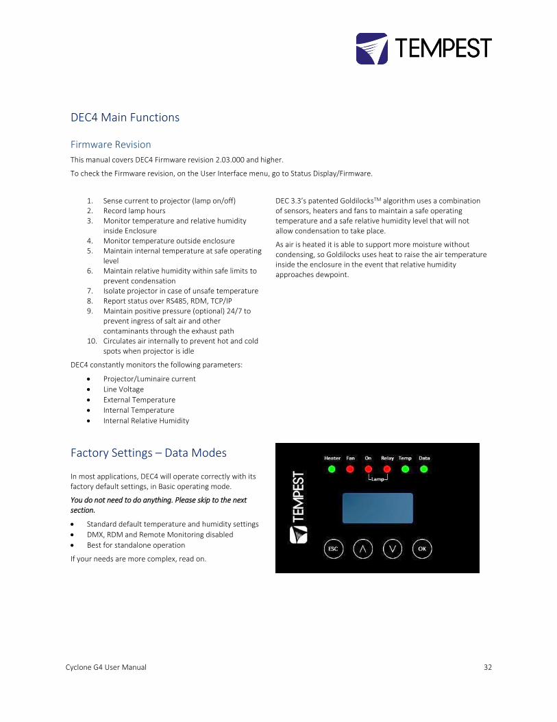
DEC4 Main Functions
Firmware Revision
This manual covers DEC4 Firmware revision 2.03.000 and higher.
To check the Firmware revision, on the User Interface menu, go to Status Display/Firmware.
1. Sense current to projector (lamp on/off) 2. Record lamp hours 3. Monitor temperature and relative humidity
inside Enclosure 4. Monitor temperature outside enclosure 5. Maintain internal temperature at safe operating
level 6. Maintain relative humidity within safe limits to
prevent condensation 7. Isolate projector in case of unsafe temperature 8. Report status over RS485, RDM, TCP/IP 9. Maintain positive pressure (optional) 24/7 to
prevent ingress of salt air and other contaminants through the exhaust path
10. Circulates air internally to prevent hot and cold spots when projector is idle
DEC4 constantly monitors the following parameters:
• Projector/Luminaire current
• Line Voltage
• External Temperature
• Internal Temperature
• Internal Relative Humidity
DEC 3.3’s patented GoldilocksTM algorithm uses a combination of sensors, heaters and fans to maintain a safe operating temperature and a safe relative humidity level that will not allow condensation to take place.
As air is heated it is able to support more moisture without condensing, so Goldilocks uses heat to raise the air temperature inside the enclosure in the event that relative humidity approaches dewpoint.
Factory Settings – Data Modes
In most applications, DEC4 will operate correctly with its factory default settings, in Basic operating mode.
You do not need to do anything. Please skip to the next section.
• Standard default temperature and humidity settings
• DMX, RDM and Remote Monitoring disabled
• Best for standalone operation
If your needs are more complex, read on.
Cyclone G4 User Manual 33
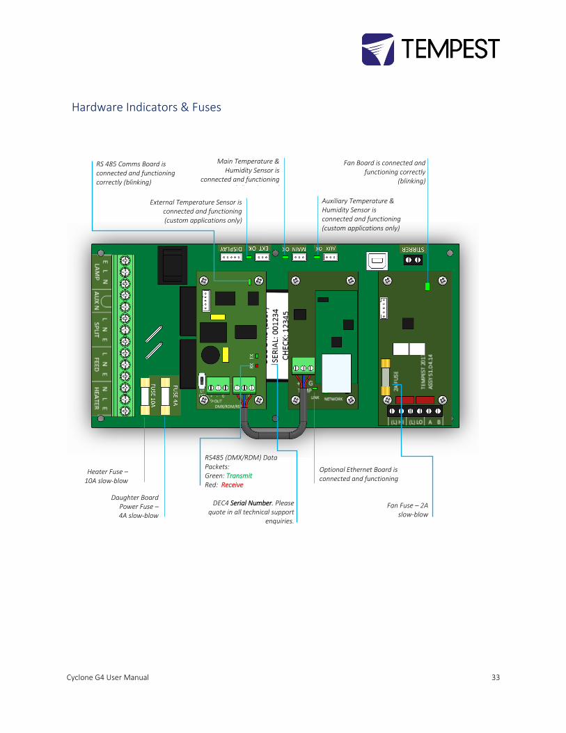
Hardware Indicators & Fuses
External Temperature Sensor is connected and functioning (custom applications only)
Main Temperature & Humidity Sensor is
connected and functioning (All Enclosures)
Auxiliary Temperature & Humidity Sensor is connected and functioning (custom applications only)
Fan Board is connected and functioning correctly
(blinking)
Optional Ethernet Board is connected and functioning
RS 485 Comms Board is connected and functioning correctly (blinking)
RS485 (DMX/RDM) Data Packets: Green: Transmit Red: Receive
Heater Fuse – 10A slow-blow
Daughter Board Power Fuse – 4A slow-blow
Fan Fuse – 2A slow-blow
DEC4 Serial Number. Please quote in all technical support
enquiries.
Cyclone G4 User Manual 34
Operating Modes
RDM Only Monitor (Factory Default)
• Supports RDM monitoring over RS485 if present
• Supports TEMP monitoring if present
• RDM Status Reporting over RS485
• RDM Configuration – settings may be changed remotely or at the enclosure user interface.
• No DMX control
RDM+DMX Control • Enclosure functions as a 1-channel DMX device, with remote control of the lamp relay
o DMX level > 75% enables normal relay operation (normally ON)
o DMX level < 25% disables normal relay operation (relay turns OFF)
o This allows you to force a hard reset of the lamp relay in the event of a projector malfunction
• RDM Status Reporting over RS485
• RDM Configuration – settings may be changed remotely or at the enclosure user interface.
• Control mode is recommended for show control applications, but can be risky in live show operation, since the DMX slot used for the enclosure MUST be kept high to prevent the lamp relay from opening.
RDM+DMX Service For trained service personnel only
• Normal operation is suspended and the enclosure functions as a 3-channel DMX device: o Lamp Relay (Slot 1) o Fans (Slot 2) o Heater (Slot 3)
• RDM Status Reporting over RS485
• RDM Configuration – settings may be changed remotely or at the enclosure user interface.
• Service mode is ONLY for troubleshooting – DO NOT use Service mode for normal operation.
Cyclone G4 User Manual 35
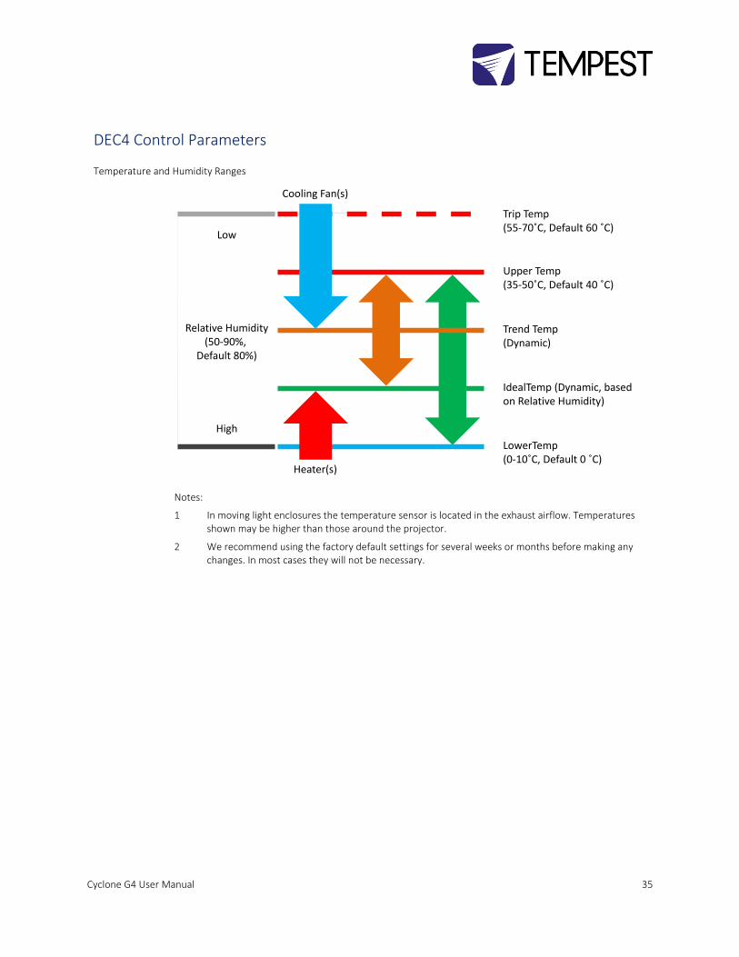
DEC4 Control Parameters
Temperature and Humidity Ranges
Notes:
1 In moving light enclosures the temperature sensor is located in the exhaust airflow. Temperatures shown may be higher than those around the projector.
2 We recommend using the factory default settings for several weeks or months before making any changes. In most cases they will not be necessary.
Trip Temp (55-70˚C, Default 60 ˚C)
Upper Temp (35-50˚C, Default 40 ˚C)
Trend Temp (Dynamic)
IdealTemp (Dynamic, based on Relative Humidity)
LowerTemp(0-10˚C, Default 0 ˚C)
Cooling Fan(s)
Heater(s)
Relative Humidity(50-90%,
Default 80%)
Low
High
Cyclone G4 User Manual 36
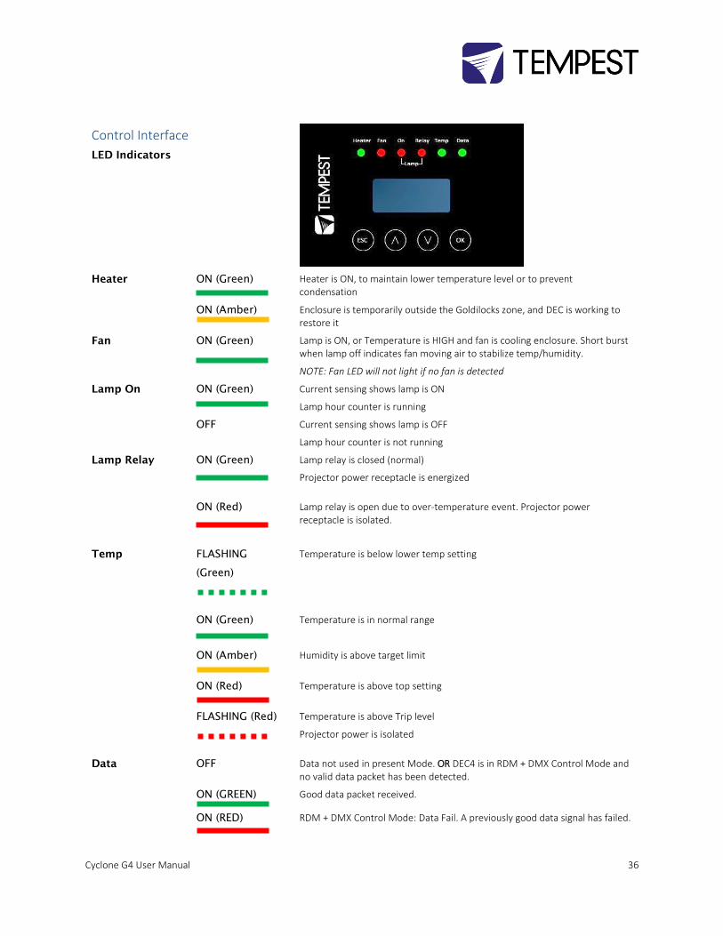
Control Interface
LED Indicators
Heater ON (Green) Heater is ON, to maintain lower temperature level or to prevent condensation
ON (Amber) Enclosure is temporarily outside the Goldilocks zone, and DEC is working to restore it
Fan ON (Green)
Lamp is ON, or Temperature is HIGH and fan is cooling enclosure. Short burst when lamp off indicates fan moving air to stabilize temp/humidity.
NOTE: Fan LED will not light if no fan is detected
Lamp On ON (Green) Current sensing shows lamp is ON
Lamp hour counter is running
OFF Current sensing shows lamp is OFF
Lamp hour counter is not running
Lamp Relay ON (Green)
Lamp relay is closed (normal)
Projector power receptacle is energized
ON (Red)
Lamp relay is open due to over-temperature event. Projector power receptacle is isolated.
Temp FLASHING
(Green)
Temperature is below lower temp setting
ON (Green) Temperature is in normal range
ON (Amber) Humidity is above target limit
ON (Red) Temperature is above top setting
FLASHING (Red)
Temperature is above Trip level
Projector power is isolated
Data OFF Data not used in present Mode. OR DEC4 is in RDM + DMX Control Mode and no valid data packet has been detected.
ON (GREEN) Good data packet received.
ON (RED) RDM + DMX Control Mode: Data Fail. A previously good data signal has failed.

Cyclone G4 User Manual 37
User Interface LCD Display
The display on the Control display provides additional status
information, depending on the operating mode:
RDM Only Monitor Mode
RDM+DMX Control Mode
RDM+DMX Service Mode
Control Interface Operation
The Control Interface is normally LOCKED.
• To UNLOCK, hold ESC and OK together for 5 seconds.
• You are now in the CONTROL MENU
• Use to scroll up and down the menu.
• Press OK to enter a menu item
• Use to set the item parameter, or to scroll to the
next menu level.
• Use ESC to go BACK, or OK to confirm settings ( ).
• To exit and LOCK, hold ESC for 5 seconds.
Menu will time out and the display will lock after ten
minutes.
(Alternating DMX Display requires a DMX
signal to be present)
Cyclone G4 User Manual 38
Control Menu
Set Data Options
SET DATA MODE
From the Front Panel, this menu item allows the user to check (and if necessary change) the Data mode.
RDM Only Monitor DEFAULT Supports RDM or TEMP if connected. No DMX Control.
RDM+DMX Service Service mode – 3 DMX slots, starting with the DMX address set
Important: Please ensure that DEC4 is NOT left in Service Mode.
RDM+DMX Control DMX (set 1 address for lamp relay) plus RDM
SET DATA ADDRESS (in RDM Only Monitor, RDM+DMX Service or RDM+DMX Control Service modes)
Select a DMX starting address in the range 001 to 510
1 – Lamp Relay
In Service Mode an addition two slots are available
2 – Fan Duty Control
3 – Heater Duty Control
Note that the DMX control is designed using a SAFETY pile-on Logic. So the DMX input can only override automatic
settings within safe limits.
SET DATA CURVE
DMX Curves affect the way the fixture relay is controlled in RDM+DMX Control Mode.
DMX levels are shown as %.
Response Curve 1 (default)
DMX level 0-25 Relay disabled (open)
DMX level 26-75 No change to relay status
DMX level 76-100 Relay enabled (normally closed)
Response Curve 2
DMX level 0-19 No change to relay status
DMX level 20-40 Relay disabled (open)
DMX level 41-59 No change to relay status
DMX level 60-80 Relay enabled (normally closed)
Cyclone G4 User Manual 39
DMX level 81-100 No change to relay status
SET DATA RESPONSE
DMX Response sets a delay time before DMX Control Mode settings are acted on. Setting a response delay of a few
seconds would prevent unintended fixture relay state changes in the event of a short accidental change in DMX
level.
NOTE: from firmware revision 0.00.100, DEC holds last valid DMX level if DMX is interrupted.
Response Delay Values are:
No Delay (default), 1, 2, 5, 10, 15, 20, 30, 60 seconds.
Set Temp Units
Choose to display temperature values in Celsius or Fahrenheit (default Celsius)
Note that temperature settings must be entered in Celsius.
Set Temp Ranges
Set three temperature trigger points for Bottom, Top and Trip temperatures, in °C.
SET TEMP LOWER (minimum temperature to be maintained)
(default 10°C, permissible range 0-10°C).
SET TEMP UPPER (maximum desired daytime temperature)
(default 45°C, permissible range 35-50°C).
SET TEMP TRIP (temperature at which load will be isolated – see note)
(default 60°C, permissible range 55-70°C).
Note: A thermal emergency is when enclosure ventilation fails with the lamp on, in which case the temperature will
rise very quickly. To avoid nuisance tripping we recommend setting a higher Trip temperature, 60°C or above.
Set Max Humidity
Sets highest desired Relative Humidity: Default 85%, permissible range 80-90%.
Note that, when the projector/luminaire lamp is OFF, the enclosure heaters will switch on to raise the temperature
and lower the risk of condensation. We recommend setting the highest Max Humidity that works in your location, to
avoid unnecessary heater use.
Set Lamp On Point
The lamp current at which DEC detects the projector/luminaire lamp is running. Default is 1 Amp, which allows for
most equipment fans and power supplies to run without changing the air in the enclosure. Lamp on point may be
set in 0.1 Amp increments between 0.2 Amps and 2.0 Amps.
If the enclosure fans never turn off, the Lamp On point is probably set below the standby current draw of the
projector/luminaire. Check the standby current draw on the display and set the Lamp on Current higher.
Cyclone G4 User Manual 40
Reset Lamp Hours
Reset each time you change the lamp in the projector.
Make this a part of your maintenance instructions.
Set Fan Function
SET FAN TEST
To test the enclosure fan(s), press [OK]
The enclosure fan will run
The Display Fan LED lights green
DEC Beeps
To stop the fan test, press [ESC]
Status Display
View current status information, using the arrow keys to scroll through:
a) Humidity – relative humidity in %
b) Internal temperature, in degrees C or F
c) External Temperature (custom enclosures with external temperature sensors only)
d) PCB temperature (this will usually be significantly higher than air temperature)
e) Voltage – line Voltage reaching the DEC
f) Current being drawn by projector/light, in Amps
g) Lamp Hours elapsed since last reset
h) Firmware version
i) UID – unique system ID number
Cyclone G4 User Manual 41
DEC4 Firmware Updates From time to time Tempest may introduce new DEC4 firmware for feature enhancements and bug fixes. Please note that the
main System Control Board (SCB) and the various optional daughter boards each have their own firmware, and it will be good
practice to update all firmware in an enclosure for optimal performance and interoperability.
• System Control Board firmware may be updated DIRECTLY using JESE JUST software and a USB cable, or INDIRECTLY,
over an RDM network, using JESE GetSet software and a JESE RDM-TRI interface.
• Fan board firmware is extremely simple and is unlikely to require updating.
• RS485 Board (51.485) firmware may be updated over an RDM network, using JESE GetSet software and a JESE RDM-TRI
interface.
All required files are available for download at http://www.tempest.biz/tech-support.php?lang=en
Indirect Firmware Updates
Requirements
Windows Laptop / PC, Windows XP through Windows 10
A JESE RDM-TRI or RDM-TXI interface and USB connection (available from Tempest).
An installed version of the JESE GetSet RDM configuration utility.
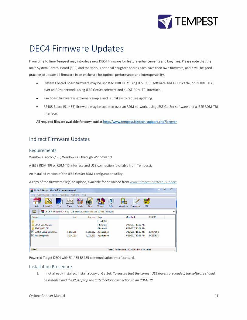
A copy of the firmware file(s) to upload, available for download from www.tempest.biz/tech_support.
Powered Target DEC4 with 51.485 RS485 communication interface card.
Installation Procedure
1. If not already installed, install a copy of GetSet. To ensure that the correct USB drivers are loaded, the software should
be installed and the PC/Laptop re-started before connection to an RDM-TRI.
Cyclone G4 User Manual 42
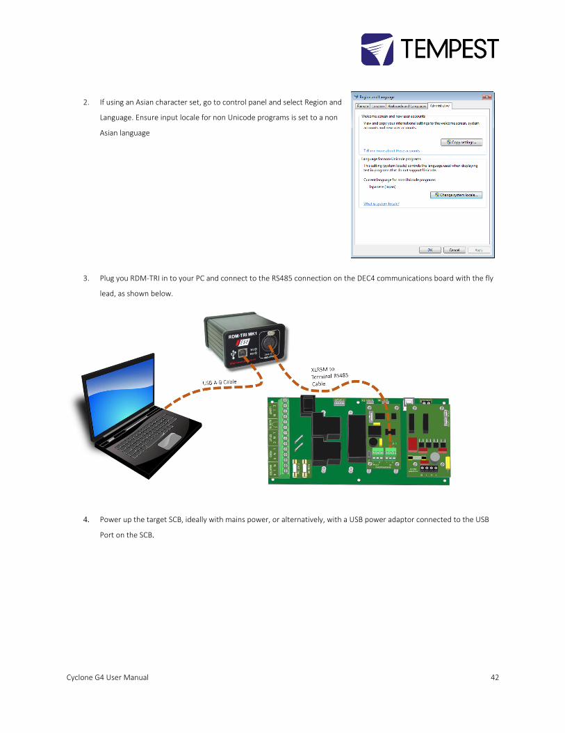
2. If using an Asian character set, go to control panel and select Region and
Language. Ensure input locale for non Unicode programs is set to a non
Asian language
3. Plug you RDM-TRI in to your PC and connect to the RS485 connection on the DEC4 communications board with the fly
lead, as shown below.
4. Power up the target SCB, ideally with mains power, or alternatively, with a USB power adaptor connected to the USB
Port on the SCB.
Cyclone G4 User Manual 43
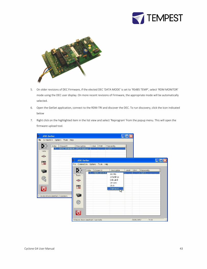
5. On older revisions of DEC Firmware, if the elected DEC ‘DATA MODE’ is set to ‘RS485 TEMP’, select ‘RDM MONITOR’
mode using the DEC user display. On more recent revisions of Firmware, the appropriate mode will be automatically
selected.
6. Open the GetSet application, connect to the RDM-TRI and discover the DEC. To run discovery, click the Icon indicated
below
7. Right click on the highlighted item in the list view and select ‘Reprogram’ from the popup menu. This will open the
firmware upload tool.
Cyclone G4 User Manual 44
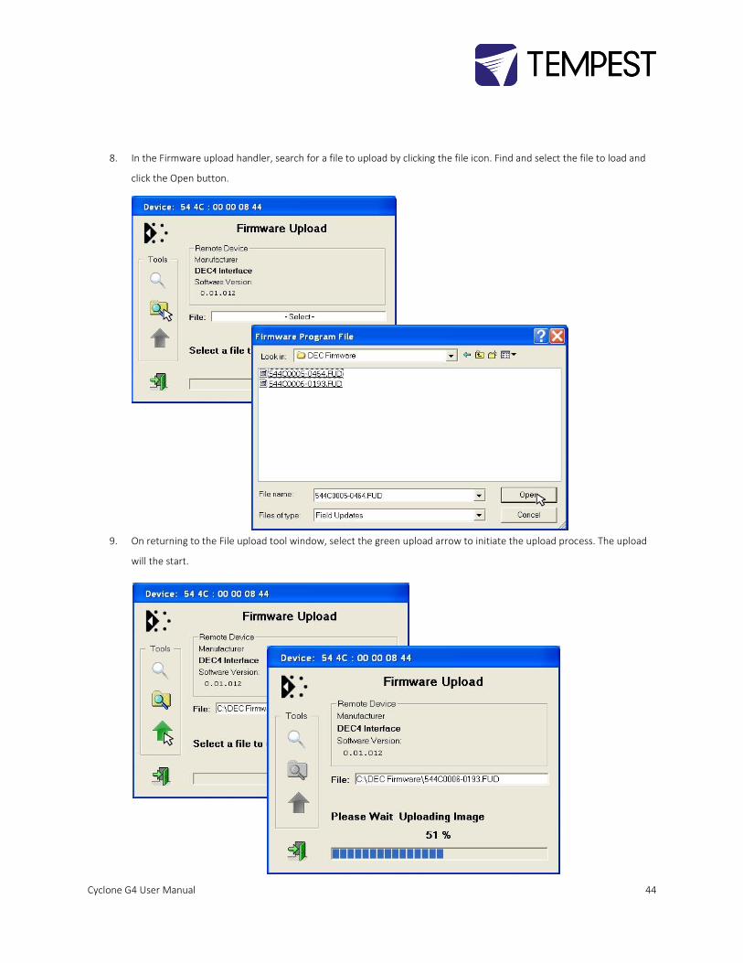
8. In the Firmware upload handler, search for a file to upload by clicking the file icon. Find and select the file to load and
click the Open button.
9. On returning to the File upload tool window, select the green upload arrow to initiate the upload process. The upload
will the start.
Cyclone G4 User Manual 45
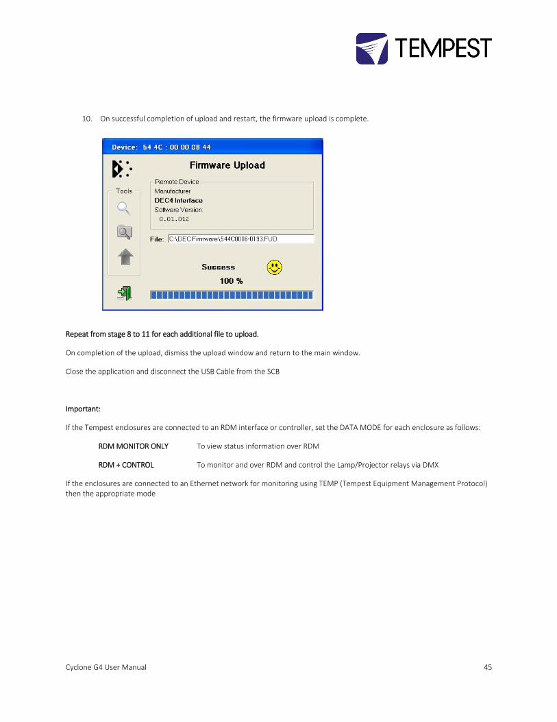
10. On successful completion of upload and restart, the firmware upload is complete.
Repeat from stage 8 to 11 for each additional file to upload.
On completion of the upload, dismiss the upload window and return to the main window.
Close the application and disconnect the USB Cable from the SCB
Important:
If the Tempest enclosures are connected to an RDM interface or controller, set the DATA MODE for each enclosure as follows:
RDM MONITOR ONLY To view status information over RDM
RDM + CONTROL To monitor and over RDM and control the Lamp/Projector relays via DMX
If the enclosures are connected to an Ethernet network for monitoring using TEMP (Tempest Equipment Management Protocol) then the appropriate mode
Cyclone G4 User Manual 46
Mounting the Projector
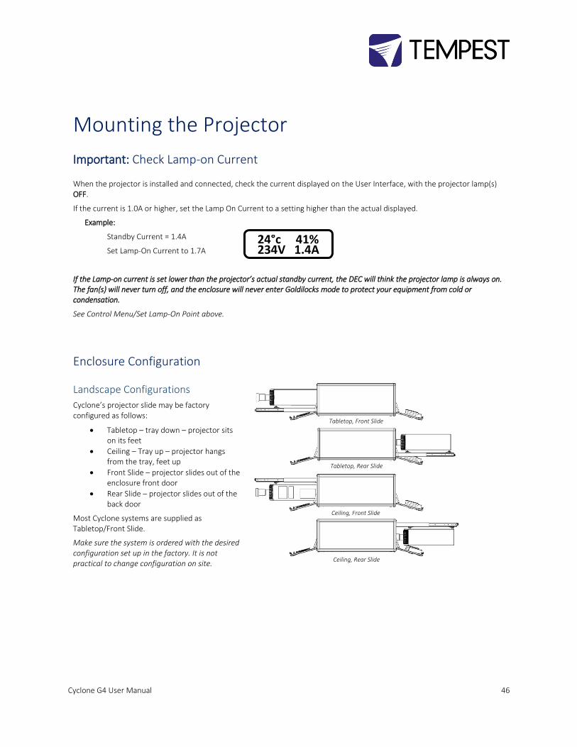
Important: Check Lamp-on Current
When the projector is installed and connected, check the current displayed on the User Interface, with the projector lamp(s) OFF.
If the current is 1.0A or higher, set the Lamp On Current to a setting higher than the actual displayed.
Example:
Standby Current = 1.4A
Set Lamp-On Current to 1.7A
If the Lamp-on current is set lower than the projector’s actual standby current, the DEC will think the projector lamp is always on. The fan(s) will never turn off, and the enclosure will never enter Goldilocks mode to protect your equipment from cold or condensation.
See Control Menu/Set Lamp-On Point above.
Enclosure Configuration
Landscape Configurations
Cyclone’s projector slide may be factory configured as follows:
• Tabletop – tray down – projector sits on its feet
• Ceiling – Tray up – projector hangs from the tray, feet up
• Front Slide – projector slides out of the enclosure front door
• Rear Slide – projector slides out of the back door
Most Cyclone systems are supplied as Tabletop/Front Slide.
Make sure the system is ordered with the desired configuration set up in the factory. It is not practical to change configuration on site.
Tabletop, Front Slide
Tabletop, Rear Slide
Ceiling, Front Slide
Ceiling, Rear Slide
24°c 41% 234V 1.4A
Cyclone G4 User Manual 47
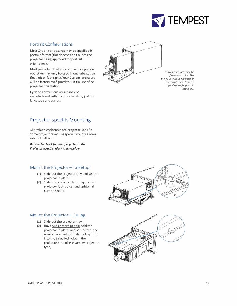
Portrait Configurations
Most Cyclone enclosures may be specified in portrait format (this depends on the desired projector being approved for portrait orientation).
Most projectors that are approved for portrait operation may only be used in one orientation (feet left or feet right). Your Cyclone enclosure will be factory configured to suit the specified projector orientation.
Cyclone Portrait enclosures may be manufactured with front or rear slide, just like landscape enclosures.
Projector-specific Mounting
All Cyclone enclosures are projector-specific. Some projectors require special mounts and/or exhaust baffles.
Be sure to check for your projector in the Projector-specific information below.
Mount the Projector – Tabletop
(1) Slide out the projector tray and set the projector in place
(2) Slide the projector clamps up to the projector feet, adjust and tighten all nuts and bolts
Mount the Projector – Ceiling
(1) Slide out the projector tray (2) Have two or more people hold the
projector in place, and secure with the screws provided through the tray slots into the threaded holes in the projector base (these vary by projector type)
Portrait enclosures may be front or rear slide. The
projector must be mounted to comply with manufacturer
specification for portrait operation.
Cyclone G4 User Manual 48
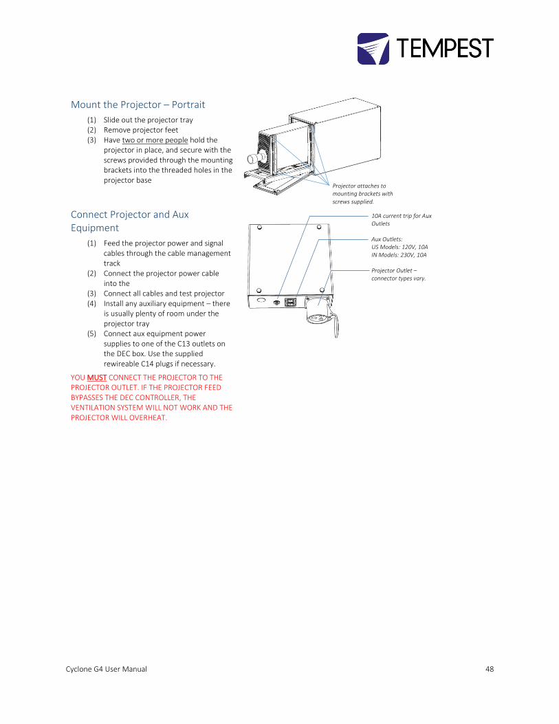
Mount the Projector – Portrait
(1) Slide out the projector tray (2) Remove projector feet (3) Have two or more people hold the
projector in place, and secure with the screws provided through the mounting brackets into the threaded holes in the projector base
Connect Projector and Aux Equipment
(1) Feed the projector power and signal cables through the cable management track
(2) Connect the projector power cable into the
(3) Connect all cables and test projector (4) Install any auxiliary equipment – there
is usually plenty of room under the projector tray
(5) Connect aux equipment power supplies to one of the C13 outlets on the DEC box. Use the supplied rewireable C14 plugs if necessary.
YOU MUST CONNECT THE PROJECTOR TO THE PROJECTOR OUTLET. IF THE PROJECTOR FEED BYPASSES THE DEC CONTROLLER, THE VENTILATION SYSTEM WILL NOT WORK AND THE PROJECTOR WILL OVERHEAT.
Projector attaches to mounting brackets with
screws supplied.
10A current trip for Aux Outlets Aux Outlets: US Models: 120V, 10A IN Models: 230V, 10A Projector Outlet – connector types vary.
Cyclone G4 User Manual 49
Projector-specific Mounting
All Cyclone enclosures are projector-specific. Some projectors require special mounts and/or exhaust baffles. Be sure to check for your projector in the Projector-specific information below.
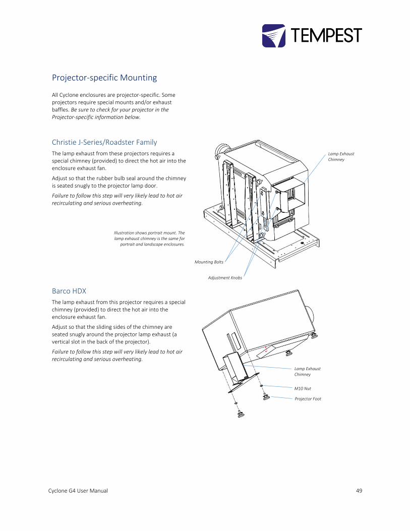
Christie J-Series/Roadster Family
The lamp exhaust from these projectors requires a special chimney (provided) to direct the hot air into the enclosure exhaust fan.
Adjust so that the rubber bulb seal around the chimney is seated snugly to the projector lamp door.
Failure to follow this step will very likely lead to hot air recirculating and serious overheating.
Barco HDX
The lamp exhaust from this projector requires a special chimney (provided) to direct the hot air into the enclosure exhaust fan.
Adjust so that the sliding sides of the chimney are seated snugly around the projector lamp exhaust (a vertical slot in the back of the projector).
Failure to follow this step will very likely lead to hot air recirculating and serious overheating.
Mounting Bolts
Adjustment Knobs
Lamp Exhaust Chimney
Illustration shows portrait mount. The lamp exhaust chimney is the same for
portrait and landscape enclosures.
Lamp Exhaust Chimney
M10 Nut
Projector Foot
Cyclone G4 User Manual 50
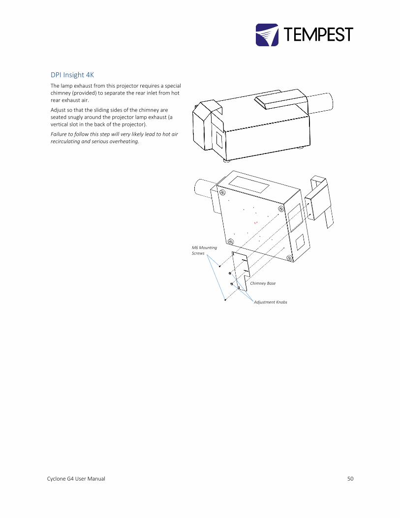
DPI Insight 4K
The lamp exhaust from this projector requires a special chimney (provided) to separate the rear inlet from hot rear exhaust air.
Adjust so that the sliding sides of the chimney are seated snugly around the projector lamp exhaust (a vertical slot in the back of the projector).
Failure to follow this step will very likely lead to hot air recirculating and serious overheating.
Chimney Base
Adjustment Knobs
M6 Mounting Screws
Cyclone G4 User Manual 51
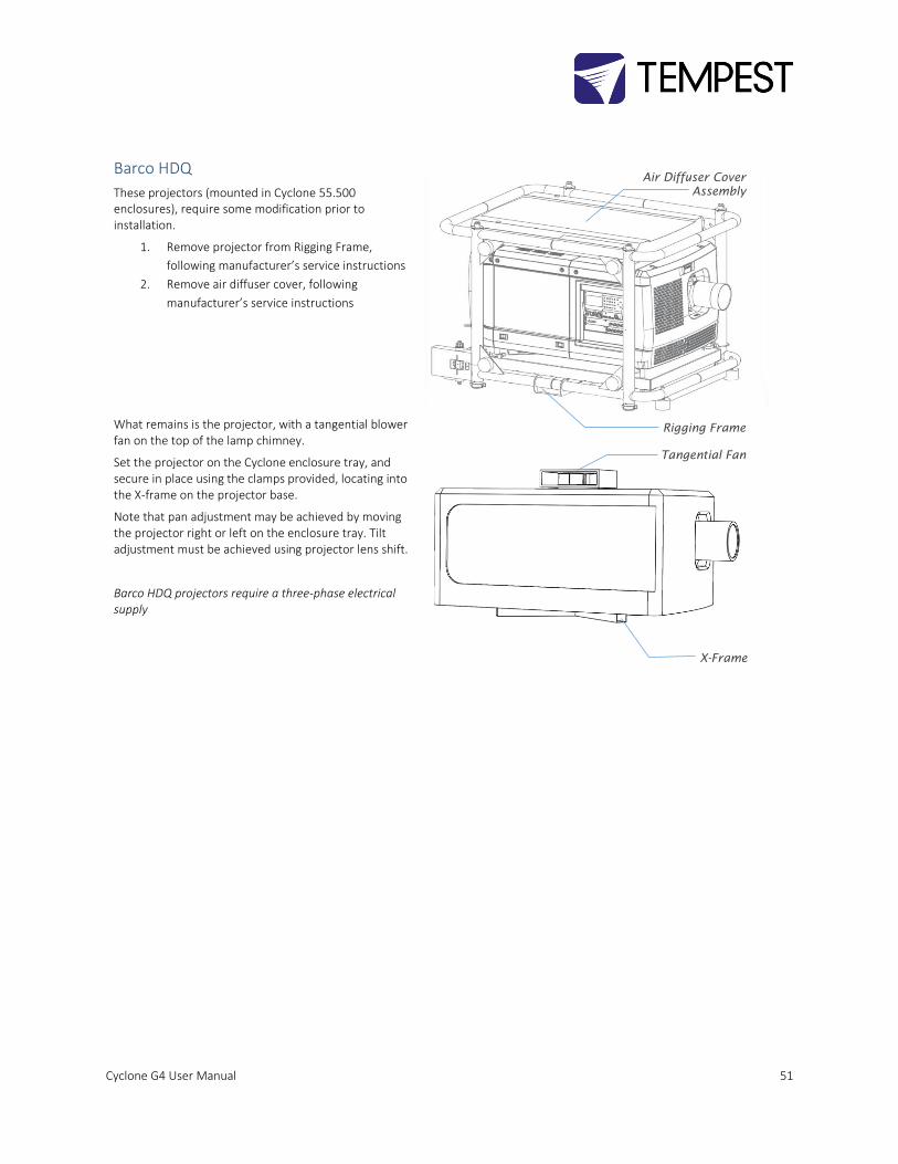
Barco HDQ
These projectors (mounted in Cyclone 55.500 enclosures), require some modification prior to installation.
1. Remove projector from Rigging Frame,
following manufacturer’s service instructions
2. Remove air diffuser cover, following
manufacturer’s service instructions
What remains is the projector, with a tangential blower fan on the top of the lamp chimney.
Set the projector on the Cyclone enclosure tray, and secure in place using the clamps provided, locating into the X-frame on the projector base.
Note that pan adjustment may be achieved by moving the projector right or left on the enclosure tray. Tilt adjustment must be achieved using projector lens shift.
Barco HDQ projectors require a three-phase electrical supply
Air Diffuser Cover
Assembly
Rigging Frame
Tangential Fan
X-Frame
Cyclone G4 User Manual 52
Routine Maintenance Check the following every six months:
Clean Port Glass
Clean port glass using a window cleaning fluid or detergent. Use a soft, lint free cloth.
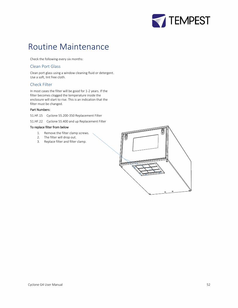
Check Filter
In most cases the filter will be good for 1-2 years. If the filter becomes clogged the temperature inside the enclosure will start to rise. This is an indication that the filter must be changed.
Part Numbers:
51.HF.15 Cyclone 55.200-350 Replacement Filter
51.HF.22 Cyclone 55.400 and up Replacement Filter
To replace filter from below
1. Remove the filter clamp screws. 2. The filter will drop out. 3. Replace filter and filter clamp.
Cyclone G4 User Manual 53
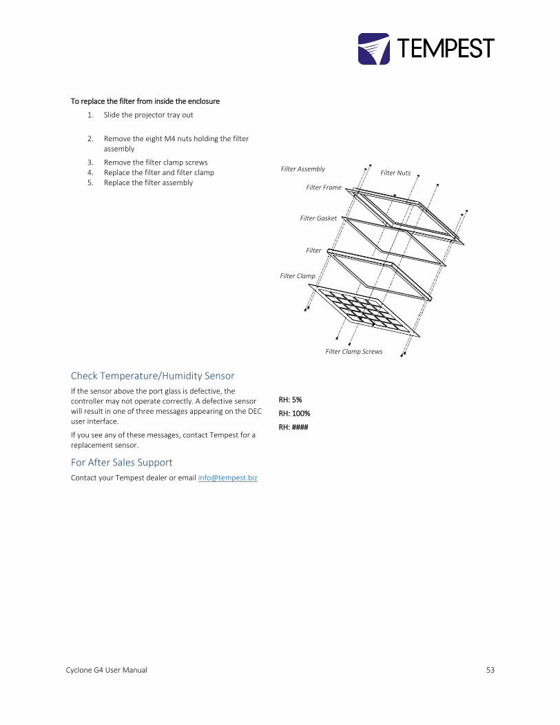
To replace the filter from inside the enclosure
1. Slide the projector tray out
2. Remove the eight M4 nuts holding the filter assembly
3. Remove the filter clamp screws 4. Replace the filter and filter clamp 5. Replace the filter assembly
Check Temperature/Humidity Sensor
If the sensor above the port glass is defective, the controller may not operate correctly. A defective sensor will result in one of three messages appearing on the DEC user interface.
If you see any of these messages, contact Tempest for a replacement sensor.
RH: 5%
RH: 100%
RH: ####
For After Sales Support
Contact your Tempest dealer or email [email protected]
Filter Assembly
Filter Clamp
Filter
Filter Gasket
Filter Frame
Filter Nuts
Filter Clamp Screws
Cyclone G4 User Manual 54
Troubleshooting
Projector does not have power:
1. Check Projector power switch 2. Check projector is plugged into DEC4 projector
outlet 3. Check that enclosure feed circuit is on 4. Check DEC4 User Interface leds are on. If feed
circuit is on and UI leds are off, check feed wiring to DEC terminals and meter DEC4 projector outlet for power
5. If UI lamp led is on and DEC4 projector outlet is live, there is a projector fault.
Enclosure overheats: 1. Is the projector connected to the DEC4 projector receptacle? If the projector is powered independently the controller has no way to know when to turn on the exhaust fans!
2. Is the filter clogged or obstructed? 3. Check that the Fan led on the UI is on when the
projector is running. If not, then the projector is probably not connected to the DEC (see 1).
4. If the fan led is on, check that the fan is running. If not, check fan wiring. If wiring is ok, fan may be faulty.
5. Check the UI display for RH (relative humidity) message. If display reads RH 5%, RH 100%, or RH###, there is a sensor fault. Contact Tempest for a replacement sensor.
Dirt/Debris inside enclosure 1. Filter is either missing or damaged? 2. Filter is not properly seated 3. Side panels or back door is not firmly latched
Water in enclosure 1. Check the drain holes in the bottom of the enclosure. If they become blocked, and water that gets in cannot escape.
2. Check seals around side panels and back door
Fan LED is on but fans do not operate The exhaust fan is protected by a 20mm 4A slow-blow fuse on the DEC4 motherboard, and a secondary fuse on the fan board. In very exceptional cases it is possible that either fuse could fail. Check visually.
The fuse is protected with a clear resin sealant and soldered to the circuit board. With care, you can de-solder the fuse and replace it, but we recommend replacing the DEC4 motherboard to maintain the integrity of the board’s conformal coating.
Heater LED is on but heater does not operate The heater is protected by a 20mm 10A slow-blow fuse on the DEC4 motherboard. In very exceptional cases it is possible that it could fail. Check visually.
The fuse is protected with a clear resin sealant and soldered to the circuit board. With care, you can de-solder the fuse and replace it, but we recommend

Cyclone G4 User Manual 55
replacing the DEC4 motherboard to maintain the integrity of the board’s conformal coating.
None of the above? Contact [email protected]

Cyclone G4 User Manual 56
Warranty
INSPECTION/WARRANTY/RETURNS.
A. Customer, at its sole expense, shall inspect all Goods promptly upon receipt and accept all Goods that conform to the specifications or catalog. All claims for any alleged defect in or failure of the Goods or Seller's performance to conform to the Contract, capable of discovery upon reasonable inspection, must be set forth in a written rejection notice detailing the alleged non-conformity, and be received by Seller within thirty (30) calendar days of Customer's receipt of the Goods. Failure by Customer to notify Seller of the alleged non-conformity within thirty (30) days will be conclusive proof that the Goods have been received by Customer without defects or damage, and in the quantities specified on the bill of lading and shall constitute an irrevocable acceptance of the Goods and a waiver of any such claim in connection with the Goods.
B. Seller warrants to Customer only that the Goods will be free from defects in material and workmanship at the time of delivery and, subject to the exceptions and conditions set forth below, for the following period (the "Warranty Period"): twelve (12) months from the date of shipment by Seller. Seller may provide additional years of warranty coverage beyond 12 months, at the rate of 2.5% of the net sale price per year, up to a total of four additional years’ coverage beyond the standard 12 month warranty period. Seller will remedy a defect as set forth in paragraph 7 D, below, (the "Warranty"). The Warranty is subject to each of the following exceptions and conditions:
1. Customer must promptly (and in all events within the Warranty Period) notify Seller of any alleged defect in a written notice (the "Notice") which shall set forth the quantity, catalog number, finish, original purchase order number, Seller's invoice number on which Goods were originally billed and a statement of the alleged defect, along with digital photographs showing such defects where feasible.
2. The Warranty shall not apply: (i) to any claimed defect that was capable of discovery upon reasonable inspection and deemed to be waived under paragraph A, above; (ii) to any Goods that have been subject to misuse, abnormal service or handling, or altered or modified in design or construction; (iii) to any Goods repaired or serviced by any person other than Seller's authorized service personnel or to Goods installed other than according to installation instructions, or (iv) with respect to normal wear and tear.
3. Seller makes no Warranty with respect to parts or components that are not the product of Seller, and specifically makes no warranty whatsoever for equipment housed inside enclosure products manufactured by Seller.
4. The Warranty is Seller's exclusive warranty with respect to the Goods. Seller makes no warranties, guarantees or representations, express or implied, to Customer except as set forth in this section. ALL OTHER WARRANTIES, EXPRESS OR IMPLIED, INCLUDING, WITHOUT LIMITATION ANY IMPLIED WARRANTY OF MERCHANTABILITY OR OF FITNESS FOR USE OR FOR A PARTICULAR PURPOSE, ARE HEREBY EXCLUDED AND DISCLAIMED.
C. Seller will accept the return of Goods properly rejected under paragraph A, above, or as to which Notice of an alleged breach of Warranty has been timely given and such Goods may be returned to Seller, freight prepaid, but only upon Customer's receipt of Seller's written return material authorization ("RMA") and shipping instructions. The RMA shall be void if the Goods are not received within 45 days after issuance of the RMA. No deduction or credit in respect of any rejected or returned Goods shall be taken until Customer has received Seller's further written deduction or credit/authorization following Seller's inspection to confirm nonconformity or defect. Seller will charge to Customer any and all costs incurred by Seller in connection with the handling, shipping, inspection and disposition of any returned Goods that are determined by Seller not to have been nonconforming upon Delivery or as to which the warranty hereunder is not applicable.
D. UPON ANY PROPER RETURN PURSUANT TO PARAGRAPH C, ABOVE, WHETHER IN CONNECTION WITH A REJECTION OF GOODS OR AN ALLEGED BREACH OF WARRANTY AND BASED UPON THE CONDITIONS SET FORTH IN THIS PARAGRAPH 7, SELLER AGREES THAT IT WILL, AS THE SOLE AND EXCLUSIVE REMEDY UNDER THE CONTRACT OR OTHERWISE, FOR ANY NONCONFORMITY OR BREACH OF WARRANTY, AND AT SELLER'S SOLE ELECTION: (i) REPAIR SUCH GOODS; OR (ii) REPLACE SUCH GOODS.
Cyclone G4 User Manual 57
Appendix – TEMP Protocol AVAILABLE TO SPECIAL ORDER
Tempest can optionally provide a firmware load that facilitates TEMP over RS485, suitable for interfacing to an Ethernet
adapter. TEMP is a lightweight proprietary ASCII based protocol, intended for rapid integration into management systems.
With TEMP and a suitable RS485 to Ethernet adaptor connected to the DEC DMX connectors, your DEC may be configured and
monitored over an IP network.
Please contact factory for ordering information.
Physical Layer
1. EITHER: Use a 51.EN Ethernet daughter board plugged directly to the DEC4 motherboard, connected to your TCP/IP
network.
2. OR: Use a 51.485 RS485 daughter board on each of a number of DEC4 motherboards, connected in a daisy-chain,
and use a 51.EN Ethernet board on the first DEC4 to connect to your TCP/IP network.
Developer’s Guide
Download the Developer Guide from www.tempest.biz/tech-support.