user manual model 865-25 ppb dissolved oxygen analyzer · pdf filemodel 865-25 ppb dissolved...
TRANSCRIPT

USER MANUAL
MODEL 865-25
ppb DISSOLVED OXYGEN ANALYZER
um-865-25-206
CONTENTS IC Controls
CONTENTSum-865-25-206
CONTENTS..................................................................2865 MENUS..................................................................3INTRODUCTION.........................................................5
Features...........................................................................5Specifications..................................................................6
865-25 D. O. MEASUREMENT................................12Introduction...................................................................12Galvanic Measuring Cell...............................................12Principles of Calibration................................................13Sample Requirements....................................................13865-25 Component Identification..................................14Description of Model 865 Analyzer...............................15
INSTALLATION.........................................................16Mounting the 865-25.....................................................16Analyzer Wiring.............................................................16Sensor Wiring................................................................17Equipment Symbols.......................................................17Assembly of the Dissolved Oxygen Sensor....................17Inserting the Sensor into the Flow cell...........................19Removal of the Sensor from Flow cell...........................19
ANALYZER OPERATION.........................................20Description of Basic Unit Controls................................20Start-up Procedure.........................................................21Initial Instrument Set-up................................................21Start-up Settings............................................................22Changing Settings..........................................................22Shutdown and Start-Up Procedure.................................23Standby Mode................................................................23
EASY MENU..............................................................24Remembers Where You Were.........................................24Home Base: Press Sample..............................................24Display Features............................................................24Arrow Keys....................................................................24
EDIT MODE...............................................................25Input On/Off Switch......................................................26Metric or Imperial Units................................................26Real-Time Clock............................................................26
CALIBRATION..........................................................27In-line Calibration.........................................................27In-line Zero Test............................................................28In-line Grab Sample.......................................................28Off-line Calibration.......................................................28Off-line Zero Test..........................................................29Calibration Errors..........................................................29Output Hold...................................................................29Temperature Compensation...........................................30Selecting Manual Temperature Compensation...............30Barometric Pressure Compensation...............................30Selecting Manual Pressure Compensation.....................31D.O. Range — Auto or Manual.....................................31Manual Ranging............................................................31Displayed Range............................................................31
ERROR MESSAGES..................................................32
Acknowledging an Error Message.................................32Error Messages for Dissolved Oxygen...........................33Error Messages for Temperature....................................34Error Messages for Pressure..........................................34Caution Messages for Alarms........................................34
OUTPUT SIGNALS...................................................35Wiring and Calibration..................................................35Reversing the 4 mA to 20 mA Output............................36Simulated 4 mA to 20 mA Output..................................36Automatic Range Switching..........................................36Enabling Output Auto-Range Switching........................36Remote Indication of Range..........................................37Unit Selection................................................................38Testing With 4 mA to 20 mA.........................................38
ALARM FUNCTIONS...............................................39Wiring and NO/NC Contacts.........................................39Use of Relay Contacts....................................................39Unit Selection................................................................40High or Low Alarm........................................................40Deviation Alarm.............................................................41Fault Alarm....................................................................41Alarm Indication............................................................41Using Alarms for On/Off Control..................................41
CONFIGURATION OF PROGRAM..........................42INSTRUMENT MAINTENANCE.............................44
Weekly Maintenance......................................................44Monthly Maintenance....................................................44Yearly Maintenance.......................................................44Sensor Chemical Cleaning.............................................45Instrument Cleaning.......................................................45
TROUBLESHOOTING..............................................46ELECTRONIC HARDWARE ALIGNMENT............47DISPLAY PROMPTS.................................................50GLOSSARY................................................................52Appendix A — Security...............................................53Appendix B — Unit Conversion.................................56Appendix C — Saturated D.O. Values........................57Appendix D — Default Settings..................................59Appendix E — Parts List.............................................60Appendix F — Installation: No Sample Panel............61Appendix G — Serial Communications......................62
Overview.......................................................................62Wiring and Configuration..............................................62ASCII Output.................................................................63IC Net™ INTELLIGENCE ACCESS............................64
DRAWINGS................................................................67D5940111: Wiring Diagram...........................................67D5970171: Analyzer Dimensions..................................68D4060084: Sample Conditioning Panel Dimensions.....69
INDUSTRIAL PRODUCTS WARRANTY................70COMPLIANCE & CONFORMITY............................71INDEX.........................................................................72
Page 2 www.iccontrols.com um-865-25-206
© Copyright 2016 IC Controls Ltd. All rights reserved.
IC Controls 865 MENUS
865 MENUS
um-865-25-206 www.iccontrols.com Page 3
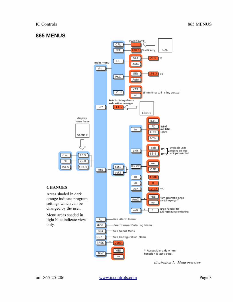
Illustration 1: Menu overview
CHANGES
Areas shaded in dark orange indicate program settings which can be changed by the user.
Menu areas shaded in light blue indicate view-only.
865 MENUS IC Controls
Page 4 www.iccontrols.com um-865-25-206
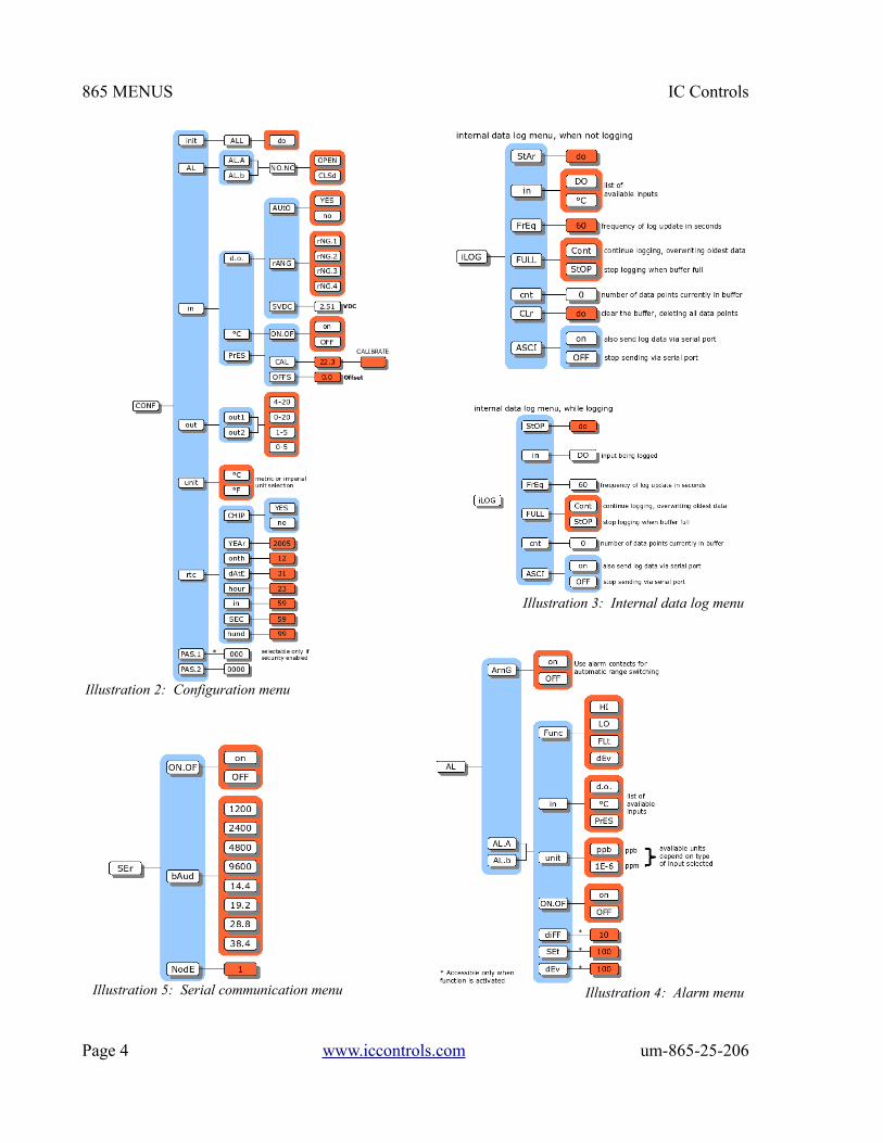
Illustration 5: Serial communication menu
Illustration 2: Configuration menu
Illustration 3: Internal data log menu
Illustration 4: Alarm menu

IC Controls INTRODUCTION
INTRODUCTIONThe model 865 is IC Controls' industrial quality remote operational low-level dissolved oxygenanalyzer, designed to give maximum flexibility, reliability, and ease-of-use. The model 865 is factorycalibrated with automatic ranging to measure dissolved oxygen from 0 ppb (parts per billion) to 20 ppm(parts per million). Calibration should not be required. It has two isolated 4 mA to 20 mA outputs, two10 A SPDT relays, dual programmable alarms plus a serial communication port. The analyzer isprogrammed to auto-calibrate, holds output during calibration, notifies user of diagnosed sensor oranalyzer faults, plus stores in memory the last 12 calibration records, 1 000 minute measurement trend,alarms, power outages, and diagnostic messages, all date and time stamped.
The model 865 is one of a series of 115/230 VAC process analyzers supplied in a corrosion resistantIP65 (NEMA 4X) water- and dust-tight case. These analyzers are also available for pH, ORP,conductivity and chlorine, plus as two-wire versions with an optional explosion-proof rating. In thecase of dissolved oxygen, the sensor is an electrochemical cell similar to a battery that produces acurrent when oxygen is present, therefore, no applied voltage is required. The analyzer conditions anddigitizes the signal for maximum accuracy, and then sends it out as a digital output and/or on 4 mA to20 mA outputs.
FeaturesThe 865 D.O. analyzer features:
1. Intuitive user friendly program; easy-to-use.
2. Auto-calibration using saturated air technique.
3. Self and sensor diagnostics.
4. Output hold during calibration.
5. Stores 12 calibration records.
6. Stores alarms, caution and error messages.
7. Stores running 1 000 minute dissolved oxygen trend.
8. Two programmable 4 mA to 20 mA outputs.
9. Two programmable alarms.
10.Serial digital output and for remote operation.
11.Three level security to protect settings.
12.Durable housing; IP65, NEMA 4X.
um-865-25-206 www.iccontrols.com Page 5
INTRODUCTION IC Controls
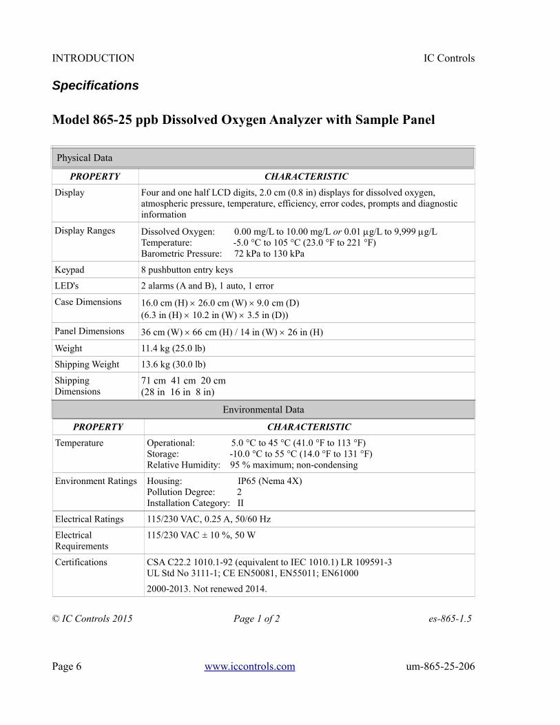
Specifications
Model 865-25 ppb Dissolved Oxygen Analyzer with Sample Panel
Physical Data
PROPERTY CHARACTERISTIC
Display Four and one half LCD digits, 2.0 cm (0.8 in) displays for dissolved oxygen, atmospheric pressure, temperature, efficiency, error codes, prompts and diagnostic information
Display Ranges Dissolved Oxygen: 0.00 mg/L to 10.00 mg/L or 0.01 g/L to 9,999 g/L Temperature: -5.0 °C to 105 °C (23.0 °F to 221 °F)Barometric Pressure: 72 kPa to 130 kPa
Keypad 8 pushbutton entry keys
LED's 2 alarms (A and B), 1 auto, 1 error
Case Dimensions 16.0 cm (H) 26.0 cm (W) 9.0 cm (D)(6.3 in (H) 10.2 in (W) 3.5 in (D))
Panel Dimensions 36 cm (W) 66 cm (H) / 14 in (W) 26 in (H)
Weight 11.4 kg (25.0 lb)
Shipping Weight 13.6 kg (30.0 lb)
Shipping Dimensions
71 cm 41 cm 20 cm(28 in 16 in 8 in)
Environmental Data
PROPERTY CHARACTERISTIC
Temperature Operational: 5.0 °C to 45 °C (41.0 °F to 113 °F)Storage: -10.0 °C to 55 °C (14.0 °F to 131 °F)Relative Humidity: 95 % maximum; non-condensing
Environment Ratings Housing: IP65 (Nema 4X)Pollution Degree: 2Installation Category: II
Electrical Ratings 115/230 VAC, 0.25 A, 50/60 Hz
Electrical Requirements
115/230 VAC ± 10 %, 50 W
Certifications CSA C22.2 1010.1-92 (equivalent to IEC 1010.1) LR 109591-3UL Std No 3111-1; CE EN50081, EN55011; EN61000
2000-2013. Not renewed 2014.
© IC Controls 2015 Page 1 of 2 es-865-1.5
Page 6 www.iccontrols.com um-865-25-206

IC Controls INTRODUCTION
Specifications
Model 865-25 ppb Dissolved Oxygen Analyzer with Sample Panel
Operational Data
PROPERTY CHARACTERISTIC
Accuracy Dissolved Oxygen: ±2 % reading or 0.1 g/L, whichever is greaterTemperature: ±0.1 °C
Precision Dissolved Oxygen: ± 2 % reading or 2 digits Temperature: ± 0.1 °C
Response Time 90% within 30 s (default), function of flow and temperature
Temperature Compensation
Auto: -5.0 °C to 105 °C (23.0 °F to 221 °F)Manual: -5.0 °C to 105 °C (23.0 °F to 221 °F)
Sample Conditions Flow: 50 mL/min to 200 mL/min Temperature: 2 °C to 45 °C (35.0 °F to 113 °F) with standard D.O. sensor, P/N A2103012. Option -80, PEEK D.O. sensor, P/N A2103042, allows for temperatures up to 65 °C (149 °F).Pressure: < 400 kPa (60 psi, 4 bar)Drain: Atmospheric
Sample Inlet ¼ in NPT tube fitting
Sample Outlet ¾ in MNPT fitting
Security 3 access-level security; partial and/or all settings may be protected via 3 and/or 4 digit security code.
Alarms Two independent, assignable, programmable, configurable, failsafe NO/NC or auto-range BCD alarm relays; SPDT, Form C, rated 10 A 115 V/5 A 230 V, 5 position BCD contact closure.
Outputs Two continuous, assignable, programmable 4 mA to 20 mA, or 0 mA to 20 mA outputs; isolated, max. load 600 Ω; Convertible from 1 VDC to 5 VDC or 0 VDC to 5 VDC.
Communication Via RS232 bidirectional serial data port; require IC NetTM 2000 software.
© IC Controls 2015 Page 2 of 2 es-865-1.5
um-865-25-206 www.iccontrols.com Page 7

INTRODUCTION IC Controls
Specifications
Sensor: A2103012
Measurement Range................................................................................................. 0.01 µg/L to 9,999 µg/L
Minimum Temperature................................................................................................................2 °C (35 °F)Maximum Temperature...........................................................................................................45 °C (113 °F)
Maximum Pressure...............................................................................................................400 kPa (60 psi)
Principle of Operation......................................................................................................................Galvanic
Electrode MaterialsCathode...................................................................................................................................................SilverAnode.......................................................................................................................................................Lead
Wetted Materials.....................................................................................Stainless Steel, PTFE, Viton, Delrin
Temperature Sensor.............................................................................................................1000 PT RTD
Optimal Flow Velocity....................................................0.83 cm3/s to 3.3 cm3/s (50 mL/min to 200 mL/min)
Electrode Dimensions Diameter....................................................................................................................................3.2 cm (1.3 in)Length......................................................................................................................................10.1 cm (4.0 in)
Process Connections.............................................................Flow cell; insertion via 1.25 in Swage-Lok nut
Sensor Cable.......................................................................................................double shielded; 1 m length
Weight........................................................................................................................................0.5 kg (1.0 lb)
Shipping Weight.......................................................................................................................1.4 kg (3.0 lb)
Shipping Dimensions................................................................................................46 cm 30 cm 23 cm (18 in 12 in 9 in)
es-A2103012-1.1
Page 8 www.iccontrols.com um-865-25-206
IC Controls INTRODUCTION
Specifications
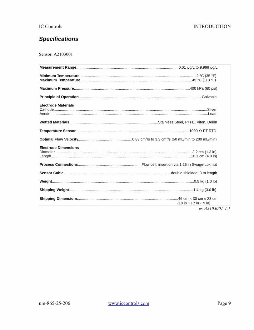
Sensor: A2103001
Measurement Range................................................................................................. 0.01 µg/L to 9,999 µg/L
Minimum Temperature................................................................................................................2 °C (35 °F)Maximum Temperature...........................................................................................................45 °C (113 °F)
Maximum Pressure...............................................................................................................400 kPa (60 psi)
Principle of Operation......................................................................................................................Galvanic
Electrode MaterialsCathode...................................................................................................................................................SilverAnode.......................................................................................................................................................Lead
Wetted Materials.....................................................................................Stainless Steel, PTFE, Viton, Delrin
Temperature Sensor.............................................................................................................1000 PT RTD
Optimal Flow Velocity....................................................0.83 cm3/s to 3.3 cm3/s (50 mL/min to 200 mL/min)
Electrode Dimensions Diameter....................................................................................................................................3.2 cm (1.3 in)Length......................................................................................................................................10.1 cm (4.0 in)
Process Connections.............................................................Flow cell; insertion via 1.25 in Swage-Lok nut
Sensor Cable.......................................................................................................double shielded; 3 m length
Weight........................................................................................................................................0.5 kg (1.0 lb)
Shipping Weight.......................................................................................................................1.4 kg (3.0 lb)
Shipping Dimensions................................................................................................46 cm 30 cm 23 cm (18 in 12 in 9 in)
es-A2103001-1.1
um-865-25-206 www.iccontrols.com Page 9

INTRODUCTION IC Controls
Specifications
Sensor: A2103042
Measurement Range................................................................................................. 0.01 µg/L to 9,999 µg/L
Minimum Temperature................................................................................................................2 °C (35 °F)Maximum Temperature...........................................................................................................65 °C (113 °F)
Maximum Pressure...............................................................................................................400 kPa (60 psi)
Principle of Operation......................................................................................................................Galvanic
Electrode MaterialsCathode...................................................................................................................................................SilverAnode.......................................................................................................................................................Lead
Wetted Materials.....................................................................................Stainless Steel, PTFE, Viton, PEEK
Temperature Sensor.............................................................................................................1000 PT RTD
Optimal Flow Velocity....................................................0.83 cm3/s to 3.3 cm3/s (50 mL/min to 200 mL/min)
Electrode Dimensions Diameter....................................................................................................................................3.2 cm (1.3 in)Length......................................................................................................................................10.1 cm (4.0 in)
Process Connections.............................................................Flow cell; insertion via 1.25 in Swage-Lok nut
Sensor Cable.......................................................................................................double shielded; 1 m length
Weight........................................................................................................................................0.5 kg (1.0 lb)
Shipping Weight.......................................................................................................................1.4 kg (3.0 lb)
Shipping Dimensions................................................................................................46 cm 30 cm 23 cm (18 in 12 in 9 in)
es-A2103042-1.1
Page 10 www.iccontrols.com um-865-25-206

IC Controls INTRODUCTION
Specifications
Sensor: A2103041
Measurement Range................................................................................................. 0.01 µg/L to 9,999 µg/L
Minimum Temperature................................................................................................................2 °C (35 °F)Maximum Temperature...........................................................................................................65 °C (113 °F)
Maximum Pressure...............................................................................................................400 kPa (60 psi)
Principle of Operation......................................................................................................................Galvanic
Electrode MaterialsCathode...................................................................................................................................................SilverAnode.......................................................................................................................................................Lead
Wetted Materials.....................................................................................Stainless Steel, PTFE, Viton, PEEK
Temperature Sensor.............................................................................................................1000 PT RTD
Optimal Flow Velocity....................................................0.83 cm3/s to 3.3 cm3/s (50 mL/min to 200 mL/min)
Electrode Dimensions Diameter....................................................................................................................................3.2 cm (1.3 in)Length......................................................................................................................................10.1 cm (4.0 in)
Process Connections.............................................................Flow cell; insertion via 1.25 in Swage-Lok nut
Sensor Cable.......................................................................................................double shielded; 3 m length
Weight........................................................................................................................................0.5 kg (1.0 lb)
Shipping Weight.......................................................................................................................1.4 kg (3.0 lb)
Shipping Dimensions................................................................................................46 cm 30 cm 23 cm (18 in 12 in 9 in)
es-A2103041-1.1
um-865-25-206 www.iccontrols.com Page 11

865-25 D. O. MEASUREMENT IC Controls
865-25 D. O. MEASUREMENT
IntroductionDissolved oxygen is a measure of the amount of oxygen, usually thought of as a gas, that is dissolved ina liquid such as water. Oxygen is essential to life, even for fish and other aquatic forms, plus is themost common element found taking part in corrosion reactions. It is this corrosion reaction thatprovides the need for the 865-25 dissolved oxygen measuring system, which is designed to measuretrace parts per billion (ppb) levels.
Mechanically hard and porous metal oxide deposits have little strength and form rapidly in the presenceof water and oxygen. Rapid corrosion will occur inside an industrial utility boiler system unlessdissolved oxygen can be virtually eliminated. Corrosion results in expensive repairs or equipmentfailures and subsequent replacement.
The model 865-25 is designed to continuously monitor the oxygen in steam and water circuits. Theoperating range of 0 ppb to 10,000 ppb allows monitoring of leaks from condensers, valves and fittings,plus very low level precision to clearly show the performance of oxygen removal equipment andchemical scavengers. Design considerations include an easy-to-use, simple and accurate calibrationapproach, ISO 9000 compatible internal memory documentation of both calibrations and recentmeasurement trends plus serial communication capability with DCS systems and evolving technology.
Galvanic Measuring CellThe 865-25 dissolved oxygen measuring sensor,P/N A2103012, is an electrochemical cell similar to abattery that produces a current when oxygen is present.By using carefully selected electrodes, in contact with anappropriate electrolyte, a chemical reaction occurs thatuses electrons gained from oxygen molecules to produce agalvanic current directly proportional to the concentrationof oxygen present. Illustration 6 shows how such anelectrode system works in a simple laboratory test.
Illustration 7 shows how these scientific principles can be implemented into a working dissolvedoxygen sensor. Also, unlike an electrolytic cell in which a flow of current produces the chemicalreaction, there is no zero-current as galvanic current is naturally zero when zero oxygen is present.
The A2103012 sensor uses a galvanic cell separated from the sample by an oxygen permeable PTFE(teflon) membrane. The cell has a silver cathode in close contact with the PTFE membrane where
oxygen (O2) gains electrons (isreduced) to become hydroxylions (OH-), and a lead (Pb)anode that produces a fixedpotential regardless of oxygenconcentration, to complete thecircuit.
Page 12 www.iccontrols.com um-865-25-206
Illustration 6: Basic galvanic cell
Illustration 7: Galvanic dissolved oxygen sensor
Silver cathodeO + 2H O + 4e -> 4OH2 2
- -
Voltometer
Lead anodePb -> Pb + 2e2- -
Electrolyte solution
Teflon membrane
Silver cathode
Lead anode
KOH fill solution
Sensor body
Insulator

IC Controls 865-25 D. O. MEASUREMENT
The chemical reactions within the cell are:
At the cathode: O2+2 H 2O+4e-=4 OH -
At the anode: 2 Pb=2 Pb2++4 e-
Overall: O2+2 H 2O+2 Pb=2 Pb(OH )2
Principles of CalibrationAt any given temperature and barometric pressure, the partial pressure of oxygen in water-saturated airis exactly the same as it is in air-saturated water. Thus a sensor can be calibrated in water-saturated air,using the 20.9% oxygen available in air as the full-scale standard, and it will correctly read dissolvedoxygen in water samples. Both temperature and barometric pressure affect the partial pressure ofoxygen in air saturated with water vapor. The 865 has microprocessor memory programmed with allthe values, as well as automatic temperature and barometric pressure sensors, so it can automaticallyobtain the correct data, look up the dissolved oxygen table, compute the correct gain, and calibrate theanalyzer. The operator need only remove the cell and suspend it over a beaker of water. Thiscalibration technique will give a 100% saturation reading for the temperature and pressure which the865 will display as ppb dissolved oxygen.
To calibrate the sensor, simply suspend the probe above water and let the analyzer auto-calibrate. Referto the Calibration section for complete procedure.
Sample RequirementsSample inlet connection:¼ inch NPT tube fitting. Suggested sample delivery tubing is 316SS with quality tube fittings toeliminate diffusion of oxygen through the sample system tube walls and leaks at fittings.
Sample outlet connection:¾ inch MNPT fitting.
Flow rate:100 mL/min to 200 mL/min is recommended, with a minimum flow rate of 50 mL/min. Lower sampleflow rates will result in slower response to ppb dissolved oxygen changes.
Temperature:2 °C to 45°C (35 °F to 113 °F) with standard D.O. sensor, P/N A2103012.2 °C to 65°C (35 °F to 149 °F) with PEEK D.O. sensor, P/N A2103042.
Pressure - less than 400 kPa (60 psi, 4 bar).
um-865-25-206 www.iccontrols.com Page 13

865-25 D. O. MEASUREMENT IC Controls
865-25 Component Identification
A) Analyzer, model 865
B) Dissolved oxygen sensor
C) Flow cell chamber
D) Flow cell outlet
E) Atmospheric pressure relief & grab sample chamber
F) Magnetite grit bypass
G) Inlet valve
H) Calibration & grit removal valve
I) Drain outlet
Page 14 www.iccontrols.com um-865-25-206
Illustration 8: 865-25 component location
IC Controls 865-25 D. O. MEASUREMENT
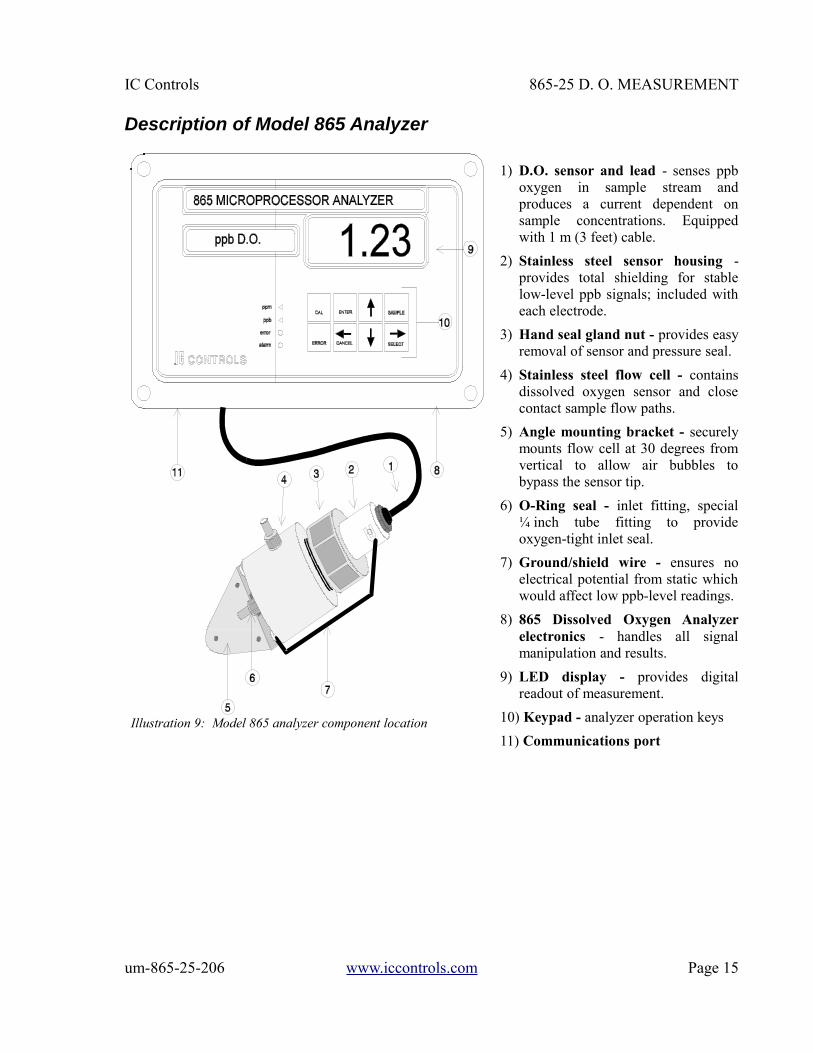
Description of Model 865 Analyzer
1) D.O. sensor and lead - senses ppboxygen in sample stream andproduces a current dependent onsample concentrations. Equippedwith 1 m (3 feet) cable.
2) Stainless steel sensor housing -provides total shielding for stablelow-level ppb signals; included witheach electrode.
3) Hand seal gland nut - provides easyremoval of sensor and pressure seal.
4) Stainless steel flow cell - containsdissolved oxygen sensor and closecontact sample flow paths.
5) Angle mounting bracket - securelymounts flow cell at 30 degrees fromvertical to allow air bubbles tobypass the sensor tip.
6) O-Ring seal - inlet fitting, special¼ inch tube fitting to provideoxygen-tight inlet seal.
7) Ground/shield wire - ensures noelectrical potential from static whichwould affect low ppb-level readings.
8) 865 Dissolved Oxygen Analyzerelectronics - handles all signalmanipulation and results.
9) LED display - provides digitalreadout of measurement.
10) Keypad - analyzer operation keys
11) Communications port
um-865-25-206 www.iccontrols.com Page 15
Illustration 9: Model 865 analyzer component location
INSTALLATION IC Controls
INSTALLATIONReport any obvious damage of shipping container to carrier and hold for inspection. The carrier, notIC Controls, is responsible for any damage incurred during shipping.
Mounting the 865-25The model 865-25 comes as a complete sample conditioning system. The analyzer is mounted on astainless steel panel with a flow cell containing the dissolved oxygen sensor. The sample conditioningpanel includes on-line calibration, magnetite grit bypass and siphon-drain system. The only installationrequirement of the user is to mount the panel and supply plumbing to the inlet and from the outlet.
The panel mounts on a wall via four ⅜ inch bolts at 12¼ inch x 24¼ inch centers; refer to drawingD4060084 for mounting dimensions. Sample inlet is a ¼ inch NPT tube fitting and sample outlet is aCPVC, ¾ inch MNPT fitting. It is suggested that the sample be delivered in a ¼ inch stainless steelline.
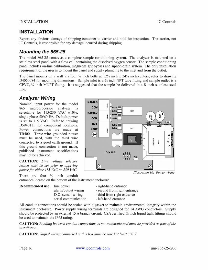
Analyzer WiringNominal input power for the model865 microprocessor analyzer isselectable for 115/230 VAC ±10%,single phase 50/60 Hz. Default poweris set to 115 VAC. Refer to drawingD5940111 for component locations.Power connections are made atTB400. Three-wire grounded powermust be used, with the third wireconnected to a good earth ground. Ifthis ground connection is not made,published instrument specificationsmay not be achieved.
CAUTION: Line voltage selectorswitch must be set prior to applyingpower for either 115 VAC or 230 VAC.
There are four ½ inch conduitentrances located on the bottom of the instrument enclosure.
Recommended use: line power - right-hand entrancealarm/output wiring - second from right entranceD.O. sensor wiring - third from right entranceserial communication - left-hand entrance
All conduit connections should be sealed with a gasket to maintain environmental integrity within theinstrument enclosure. Power supply wiring terminals are designed for 14 AWG conductors. Supplyshould be protected by an external 15 A branch circuit. CSA certified ½ inch liquid tight fittings shouldbe used to maintain the IP65 rating.
CAUTION: Bonding between conduit connections is not automatic and must be provided as part of theinstallation.
CAUTION: Signal wiring connected in this box must be rated at least 300 V.
Page 16 www.iccontrols.com um-865-25-206
Illustration 10: Power wiring

IC Controls INSTALLATION
Sensor WiringThe basic wiring scheme for all IC ControlsD.O. sensors is shown in illustration 11. Thiswiring scheme is intended for cable lengthsless than 3 meters (10 feet) where electricalinterference is expected not to be severe. TheD.O. sensor at 1 ppb D.O. produces less than1 µA. It is recommended that the sensor belocated as near as possible to the dissolvedoxygen analyzer to minimize any effects ofambient electrical noise interference. All long,low-level D.O. sensor signals should be runthrough a dedicated conduit. Take care toroute D.O. signal wiring away from AC powerlines to minimize unwanted electricalinterference.
When installing any instrument cable in conduit, use caution to avoid scraping or cutting the cableinsulation—resulting exposure of the cable’s internal shield wire will greatly increase the chances ofsystem malfunction at any given time. Avoid excessive twisting or coiling of all instrument cable tominimize possibilities for broken wire. Make sure all connections are clean and tight.
Equipment Symbols
Caution (refer to accompanying documents)
Protective conductor terminal
Assembly of the Dissolved Oxygen SensorThis procedure should be done over a sink. Wear thin plastic or rubber gloves and protective eye wearas the electrolyte is a caustic solution. Wash hands thoroughly with lots of water if the electrolytecomes in contact with the skin. Rinse until the slippery feel of the caustic disappears.
NOTE 1: The D.O. sensor should be assembled and charged while connected to the analyzer with thepower on. The analyzer presents a current route for the electrons released from oxygen in the air. Ifthe sensor cannot be connected to the analyzer during assembly/charging, short the D.O. + lead andD.O. - lead (refer to illustration 11) to provide an alternate current path. Failure to provide a currentpath will result in secondary undesirable reactions with byproducts that slow the sensor response whenplaced in service.
NOTE 2: Ensure all air bubbles are removed during assembly. Air has 20.9 % oxygen or in parts perbillion, 209,000,000 ppb. Water is saturated with dissolved oxygen at 8,240 ppb (refer to Appendix B;25 °C and 101.3 kPa) so an air bubble can saturate about 25,000 times as much water, or at 1 ppb canadd an extra ppb to 25,000,000 times as much sample.
1) Remove the protective cap exposing the lead coils and silver tip. Inspect the sensor to ensure thecoils are clean and the silver electrode is bright. If the coils are tarnished, wipe in the direction ofcoils with a low-lint paper towel.NOTE: Ensure brown sealing O-ring is seated in sensor groove.
um-865-25-206 www.iccontrols.com Page 17
Illustration 11: Sensor wiring
-TEMP
+TEMP
(WHT)TB201
D.O. +
D.O. SHIELD
D.O. -
(GRN)
(COM CTR)
(COM SHD)
TB200
(RED)

INSTALLATION IC Controls
2) Hold the retainer tip at about 60 degrees and addtwo drops of electrolyte. Then install themembrane module in the cap with the membranefacing down so that it covers the center hole inthe cap as per illustration 12. Push the membranemodule firmly in to force the electrolyte dropsaround the cap bottom displacing any air.
3) Holding the retainer tip (with membrane moduleinstalled) in an upright position, fill withelectrolyte until the center cavity is full. Tilt atabout 60 degrees and add an extra ⅛ inch ofelectrolyte, observing that the crack around themembrane module fills with electrolyte and air isdisplaced.
4) Hold the assembled retainer tip and slowly lowerthe electrode coils (see illustration 13) down intothe cap until the threads touch. Raise and repeatensuing all air is displaced around the coils.
5) Rotate the sensor body until you can see the flat area through the threads. Slowly rotate the cap on,allowing the excess electrolyte and bubbles to overflow up the flat. Lightly tap the cap to dislodgeair bubbles. Continue to slowly rotate the cap until a firm stop is reached.CAUTION: Do not force the cap beyond the stop; the parts are plastic and can break.
6) Dry the D.O. sensor and blot the tip. Examinethe tip - the membrane should be smooth withno wrinkles or cuts and the surface contours ofthe silver electrode should be clear. Thereshould be no lines from trapped air bubblesbetween the membrane and the silver electrode.If there are no visible problems, the D.O.sensor is ready to be put into service. A sensorwith no air inside will come down in a fewminutes. A sensor with trapped air inside willcome down to 1 ppb in several hours or days.If there are wrinkles, lines from large airbubbles or tiny air bubbles present,disassemble and re-charge the sensor.
Page 18 www.iccontrols.com um-865-25-206
Illustration 13: Sensor assembly
Illustration 12: Membrane module assembly
0-RING GROOVE
SENSOR
MEMBRANE MODULE
MM CAP
O-RING
Flat for bubblerelease
60 degreeangle

IC Controls INSTALLATION
Inserting the Sensor into the Flow cell1) Inspect the inside of the flow cell for any foreign matter; wipe out if necessary. It should appear
clean, shiny, and bright.
2) Insert the assembled sensor through the nut and sealing teflon ring.
3) Press slowly all the way down until the sensor firmly reaches the stop.
4) By hand, tighten the nut firmly to get a good seal. This should be sufficient for 5 psi to 10 psipressure. Give the nut an extra quarter turn beyond finger tight to keep out tramp oxygen.NOTE: The flow cell is not intended for use at high pressure. The teflon seal ring is not designedto hold against pressure.
Removal of the Sensor from Flow cell1) Stop the sample flow to the dissolved oxygen sensor and vent the sample line to atmosphere.
2) Unscrew the nut and gently remove the dissolved oxygen sensor.CAUTION: Removal of the dissolved oxygen sensor from a sealed flow cell will vacuum stretch thethin dissolved oxygen sensing membrane. Stretching the membrane will cause slow response andhigher readings at low ppb levels. Parting the membrane will cause dissolved oxygen sensorfailure.
3) When the dissolved oxygen sensor has been fully removed, wipe the sensor clean and then proceedto the calibration procedure or maintenance section, as necessary.
um-865-25-206 www.iccontrols.com Page 19
ANALYZER OPERATION IC Controls
ANALYZER OPERATION
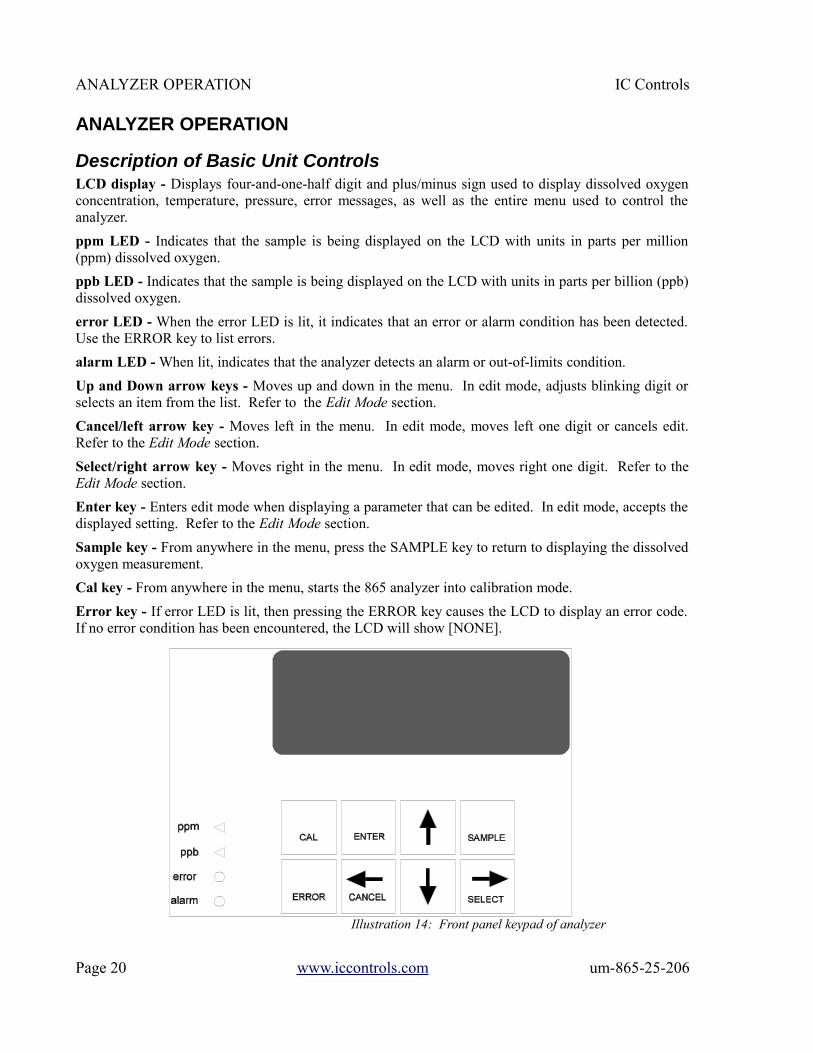
Description of Basic Unit ControlsLCD display - Displays four-and-one-half digit and plus/minus sign used to display dissolved oxygenconcentration, temperature, pressure, error messages, as well as the entire menu used to control theanalyzer.
ppm LED - Indicates that the sample is being displayed on the LCD with units in parts per million(ppm) dissolved oxygen.
ppb LED - Indicates that the sample is being displayed on the LCD with units in parts per billion (ppb)dissolved oxygen.
error LED - When the error LED is lit, it indicates that an error or alarm condition has been detected.Use the ERROR key to list errors.
alarm LED - When lit, indicates that the analyzer detects an alarm or out-of-limits condition.
Up and Down arrow keys - Moves up and down in the menu. In edit mode, adjusts blinking digit orselects an item from the list. Refer to the Edit Mode section.
Cancel/left arrow key - Moves left in the menu. In edit mode, moves left one digit or cancels edit.Refer to the Edit Mode section.
Select/right arrow key - Moves right in the menu. In edit mode, moves right one digit. Refer to theEdit Mode section.
Enter key - Enters edit mode when displaying a parameter that can be edited. In edit mode, accepts thedisplayed setting. Refer to the Edit Mode section.
Sample key - From anywhere in the menu, press the SAMPLE key to return to displaying the dissolvedoxygen measurement.
Cal key - From anywhere in the menu, starts the 865 analyzer into calibration mode.
Error key - If error LED is lit, then pressing the ERROR key causes the LCD to display an error code.If no error condition has been encountered, the LCD will show [NONE].
Page 20 www.iccontrols.com um-865-25-206
Illustration 14: Front panel keypad of analyzer
IC Controls ANALYZER OPERATION
Start-up Procedure1. Install the model 865-25 according to the instructions in Installation section.
Verify power supply has been wired for proper voltage and instrument is suitably grounded.
2. Turn on flow at sample inlet.
3. Power up the 865 analyzer. The startup procedure will begin by alternately flashing [tESt] and [----]while performing the memory tests.
4. The analyzer will display in sequence the analyzer model number, in this case [865], and theprogram version number, e.g. [2.01].
5. The display test lights each of the implemented display segments in turn. At the same time, each ofthe LEDs will be lighted in turn.
6. If the analyzer passes all the tests, then the hardware is functioning properly and the analyzer willproceed to display dissolved oxygen.
7. If the analyzer displays +Err, this indicates that the dissolved oxygen input is off-scale. The errorLED will be lighted as long as either the dissolved oxygen or the temperature input is off-scale. Anoff-scale error can indicate that a sensor is not in solution, is off-scale, or is not connected properly.If the error LED remains lighted, then press the ERROR key or select [Err] from the main menu, tosee what errors have been detected by the analyzer.
8. After completing the above steps, the monitor is now in normal operational mode. Analyzer settingsand parameters can be viewed and/or changed at any time using the keypad.
Initial Instrument Set-upRefer to Appendix D for a list of factory default settings used by the analyzer. Before putting theanalyzer into operation, verify the analyzer settings to ensure that they agree with the intended set-up.
1) To change the alarms: set alarm function (high, low, deviation, fault alarm), input source (D.O.,temperature, or pressure), differential, set-point, and on/off switch. Set the normally open/normallyclosed configuration of the alarm contacts in [CONF] [AL]. The program setting must reflect theactual NO/NC wiring. Refer to Alarm Functions section for complete details.
2) To change the 4 mA to 20 mA outputs: set input source (D.O., temperature, pressure), zero, span,and on, or if not used, off switch. Each output can be calibrated for 4 mA to 20 mA, 0 mA to 20mA (or 1 VDC to 5 VDC or 0 VDC to 5 VDC using a 250 ohm 1% resistor across the terminals).Refer to Outputs section for complete details.
3) Set preferences for metric or imperial units in [CONF] [unit].
4) If desired, install password security. Refer to Appendix A for complete details.
um-865-25-206 www.iccontrols.com Page 21
ANALYZER OPERATION IC Controls
Start-up SettingsThe 865 dissolved oxygen analyzer uses a sensor with a galvanic cell which has an electrochemical zerocurrent output at 0 ppb dissolved oxygen. Full-scale calibration is easily done using atmospheric air asthe oxygen standard. The 865 needs only to have the operator remove the cell, expose it to air, plusenter the calibrate command. All stabilization, temperature and pressure compensation, plus calibrationadjustments are automatic.
Temperature plays a major role in dissolved oxygen readings. The 865 has stored temperature vs.dissolved oxygen tables in it's memory. A temperature detector is in close contact with the dissolvedoxygen sensing tip in the sample. The temperature sensor can be field calibrated but comes from thefactory pre-calibrated.
Pressure also plays a significant role during calibration. The 865 has stored pressure vs. dissolvedoxygen tables stored in it's memory. A pressure sensor is supplied for automatic pressure compensation.
Refer to Appendix C for a table of saturated D.O. values at various temperatures and pressures.
Changing SettingsAnalyzer settings and parameters can be viewed and/or changed at any time. Refer to the menus onpages 3 and 4; the areas shaded in dark orange indicate program settings which can be changed by theuser. Menu areas shaded in light blue are view-only menus.
Page 22 www.iccontrols.com um-865-25-206
IC Controls ANALYZER OPERATION
Shutdown and Start-Up ProcedureSample interruption less than 72 hours: If the analyzer will not have flow for less than 72 hours, butwill have low ppb sample in the flow cell, leave the instrument on and either neglect its output or putthe analyzer in standby mode.
Sample interruption greater than 72 hours: If no sample flow is expected for longer than 72 hours,perform the following shutdown procedure. This procedure will prevent possible build-up of oxidationproducts in the sensor.
SHUTDOWN PROCEDURE
1) Leave power on.
2) Turn off sample flow prior to the flow cell inlet.
3) Close the drain from flow cell to prevent oxygen from entering flow cell.
4) Keep flow cell full of ppb dissolved oxygen water. Since the sensor consumes small quantities ofdissolved oxygen, it will store for months in a sealed flow cell if the power is on, or, if the cell leadsare shorted; D.O. + and D.O. -.
5) If it is necessary to turn the analyzer power off; first remove and disassemble the sensor over a drainwhile it is still wired to the analyzer (refer to step 6 to step 9). Use the analyzer display reading toindicate the sensor is clean when it drops to low ppb levels.
6) Remove white sensor cap and membrane module.
7) Rinse electrodes with pure water and wipe dry to remove any trace of internal fill solution. Using aclean low lint paper towel, tighten the lead coils and wipe to a bright condition.
8) Rinse membrane module, blot dry, and store in original plastic case in which it was shipped.
9) Place the white sensor cap onto the sensor and store the sensor in it's box.
10)Turn off power. A disassembled sensor stored in a clean dry container can keep for years.
START-UP, IF STORED IN A SEALED FLOW CELL
1) Open the drain valve.
2) Open the sample inlet valve.
3) The system is ready to measure ppb dissolved oxygen.
START-UP, IF STORED DISASSEMBLED AND DRY
Refer to Assembly of the Dissolved Oxygen Sensor in the Installation section.
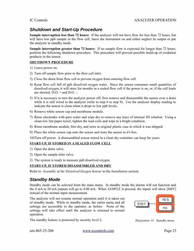
Standby ModeStandby mode can be selected from the main menu. In standby mode the alarms will not function andthe 4 mA to 20 mA outputs will go to 4.00 mA. When SAMPLE is pressed, the inputs will show [StbY]instead of the normal input measurement.
The analyzer will not resume normal operation until it is taken outof standby mode. While in standby mode, the entire menu and allsettings are accessible to the operator, as before. None of thesettings will take effect until the analyzer is returned to normaloperation.
The standby feature is protected by security level 2.
um-865-25-206 www.iccontrols.com Page 23
Illustration 15: Standby menu

EASY MENU IC Controls
EASY MENUThe layout of the program is shown in the 865 Menus starting on page 3.
Remembers Where You WereThe analyzer remembers where SAMPLE is. The sample display is home base for the program.The program also remembers which menu selections were used last and loops around the columns. Themenu can be accessed using the arrow keys to find any parameter then press SAMPLE to return to thedisplayed reading. Then using the Right arrow key return to exactly where you were.
Home Base: Press SampleFrom anywhere in the menu, the SAMPLE key can be used to return todisplaying dissolved oxygen. The program will safely abort whatever itwas doing at the time and return to displaying the dissolved oxygenreading.
The dissolved oxygen display is the default sample display for theanalyzer. The analyzer's inputs, dissolved oxygen, temperature, andpressure, are arranged underneath each other at the left-hand side of themenu. Use the Up or Down arrow key to display each of the readings inturn.
Display Features1. The analyzer has a built-in timer which returns the program to displaying dissolved oxygen if no key
is pressed for 15 minutes. This time-out has the same effect as pressing the SAMPLE key. Ifsecurity has been enabled, then the time-out will change the access level back to 0 or 1 automaticallywhich gives the user read-only access. The user will have to enter an appropriate password to go toa higher access level. If output hold for D.O. is in effect, the same timer will release output hold.
2. When the sample value is displayed, pressing the Left arrow key will show which of dissolvedoxygen, temperature, or pressure is displayed. Pressing Right arrow key displays the sample readingagain.
3. The temperature and pressure input can effectively disappear from the menu if they are turned off inthe configuration menu. To change the configuration, refer to Input On/Off Switch section in theEdit Mode section.
4. The main sample, ie. the input that is displayed first when the SAMPLE key is pressed, can bechanged. By default the main input is [d.o.]. Change the default in [CONF] [in] [dFLt].
Arrow KeysThe four arrow keys on the keypad are used to move around in the menu.
Example:Press SAMPLE to make sure that display is at home base. Press the Right arrow key. One of theprompts in the column starting with [d.o.] (refer to illustration 1) will be displayed. Use the Up orDown arrow keys to display the prompt above or below. If the prompt at the top or the bottom isdisplayed, the program will loop around. Press the Up or Down key until [AL] is displayed. Press theLeft key to return to the sample display. Press the Right key again and [AL] will be displayed.
Page 24 www.iccontrols.com um-865-25-206
Illustration 16: Home base
IC Controls EDIT MODE
EDIT MODEEdit mode is used to change a numeric value or to select between different options. Values and settingswhich can be edited are identified by the darker shading in the menu. Any frame which has a whitebackground cannot be modified.
Editing by Selecting a Setting
Editing a value is like picking an option from a list; only one item on the list can be seen at a time. Tochange the setting, press ENTER to go into edit mode; the display will start blinking. Use the Up orDown arrow key to switch between the possible options and then press ENTER again to accept the newsetting and leave edit mode.
Example: Turn alarm A off.
From the menu, select [Al] [Al.A] [ON.OF]. The analyzer will now display either [on] or [OFF], whichare the two choices. To change the setting, press ENTER to go into edit mode; the display will startblinking. Use the Up or Down arrow key to switch between the possible options. When [on] isdisplayed, press ENTER again to accept the new setting and leave edit mode.
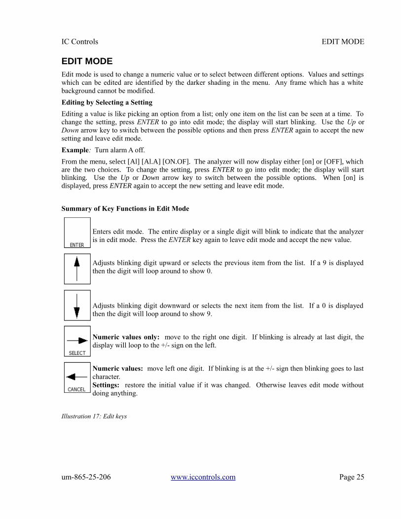
Summary of Key Functions in Edit Mode
Enters edit mode. The entire display or a single digit will blink to indicate that the analyzeris in edit mode. Press the ENTER key again to leave edit mode and accept the new value.
Adjusts blinking digit upward or selects the previous item from the list. If a 9 is displayedthen the digit will loop around to show 0.
Adjusts blinking digit downward or selects the next item from the list. If a 0 is displayedthen the digit will loop around to show 9.
Numeric values only: move to the right one digit. If blinking is already at last digit, thedisplay will loop to the +/- sign on the left.
Numeric values: move left one digit. If blinking is at the +/- sign then blinking goes to lastcharacter.Settings: restore the initial value if it was changed. Otherwise leaves edit mode withoutdoing anything.
Illustration 17: Edit keys
um-865-25-206 www.iccontrols.com Page 25

EDIT MODE IC Controls
Input On/Off SwitchThe temperature input has been provided with an on/off switch. The most common use of this feature isto “turn off” the temperature input if no temperature compensator or temperature sensor has beeninstalled. Turning off the temperature input will make the temperature [°C] or [°F] display at the leftside of the menu disappear, as if it did not exist.
Refer to illustration 2 for the configuration menu; select [CONF] [in] [°C] [ON.OF] and edit asrequired.
Metric or Imperial UnitsBy default, the analyzer will use metric units. This means that temperature will be displayed usingdegrees Celsius and that the prompt for the temperature input will be [°C]. Using metric units, thepressure is displayed as kPa. The analyzer can be made to use imperial units. Using imperial units,temperature will be displayed using degrees Fahrenheit and the prompt for the first temperature inputwill be [°F] instead of [°C]. Pressure will be displayed as psi throughout the program.
For practical reasons, the temperature input is always identified as [°C] throughout this instructionmanual and in the menus.
To select imperial units for the analyzer, select [unit] from the configuration menu, [CONF], then gointo edit mode and change the [°C] prompt to [°F]. Since this is a global setting, both the units used fortemperature and for pressure will change.
Real-Time ClockThe 865 analyzer has an internal date/time clock which allows the analyzer to maintain the date andtime even when the analyzer is powered off. The date and time are needed to accurately date/timestamp the internal data log plus system and calibration event tags.
To set the real-time clock, select [CONF] [rtc] from the menu. Set the year, month, day, hour, minute,and second. The [hund] frame displays hundreds of a second but cannot be edited.
The [rtc] [CHIP] frame will show [YES] when a real-time clock chip is present, and shows [NO] whenno real-time clock capability has been installed in the hardware. This frame cannot be edited.
Page 26 www.iccontrols.com um-865-25-206
IC Controls CALIBRATION
CALIBRATIONWhen executing the calibration procedure, the analyzer will adjust the efficiency constant for thedissolved oxygen cell. Calibration is performed in air over water, at 100% humidity for optimalaccuracy. A zero oxygen measurement can also be checked using zero dissolved oxygen standard,P/N A1100193.
There are two methods available for performing a calibration, in-line calibration or off-line calibration.
NOTE: Before starting a calibration, the analyzer needs to use automatic range switching or manualrange, [rNG.4], must be selected. Calibrating using manual range [rNG.1], [rNG.2] or [rNG.3], willgenerate error 1.3.
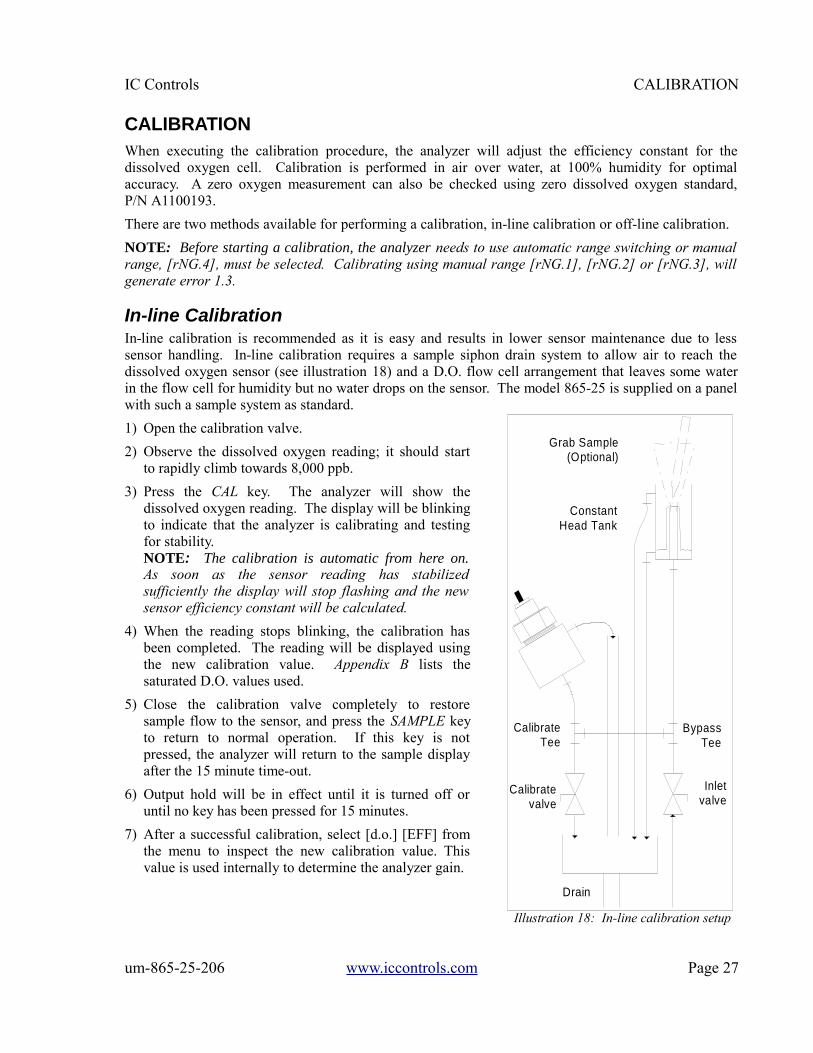
In-line CalibrationIn-line calibration is recommended as it is easy and results in lower sensor maintenance due to lesssensor handling. In-line calibration requires a sample siphon drain system to allow air to reach thedissolved oxygen sensor (see illustration 18) and a D.O. flow cell arrangement that leaves some waterin the flow cell for humidity but no water drops on the sensor. The model 865-25 is supplied on a panelwith such a sample system as standard.
1) Open the calibration valve.
2) Observe the dissolved oxygen reading; it should startto rapidly climb towards 8,000 ppb.
3) Press the CAL key. The analyzer will show thedissolved oxygen reading. The display will be blinkingto indicate that the analyzer is calibrating and testingfor stability.NOTE: The calibration is automatic from here on.As soon as the sensor reading has stabilizedsufficiently the display will stop flashing and the newsensor efficiency constant will be calculated.
4) When the reading stops blinking, the calibration hasbeen completed. The reading will be displayed usingthe new calibration value. Appendix B lists thesaturated D.O. values used.
5) Close the calibration valve completely to restoresample flow to the sensor, and press the SAMPLE keyto return to normal operation. If this key is notpressed, the analyzer will return to the sample displayafter the 15 minute time-out.
6) Output hold will be in effect until it is turned off oruntil no key has been pressed for 15 minutes.
7) After a successful calibration, select [d.o.] [EFF] fromthe menu to inspect the new calibration value. Thisvalue is used internally to determine the analyzer gain.
um-865-25-206 www.iccontrols.com Page 27
Illustration 18: In-line calibration setup
Calibrate valve
CalibrateTee
Inletvalve
Drain
BypassTee
Constant Head Tank
Grab Sample (Optional)
CALIBRATION IC Controls
In-line Zero TestAn in-line zero dissolved oxygen check can be performed by closing the inlet valve and allowing thesample to drain completely; then closing the calibration valve securely. Pour the zero D.O. standard,P/N A1100193, into the constant head tank standpipe until it overflows from the flow cell to drain.
In-line Grab SampleAn in-line grab sample dissolved oxygen check can be performed by inserting a grab sample funnel intothe constant head tank standpipe and allowing it to overflow. When the sample has overflowed for acouple of minutes - to rinse down to ppb levels - insert your vial and break the tip. Keep the tipsubmerged for a minute to let the color develop, then move quickly following test instructions to getyour reading before air introduces an error.
Off-line Calibration1) Turn off sample flow.
2) Remove the sensor from flow cell. Refer to Removal of the Sensor from Flow Cell in theInstallation section for proper procedure.
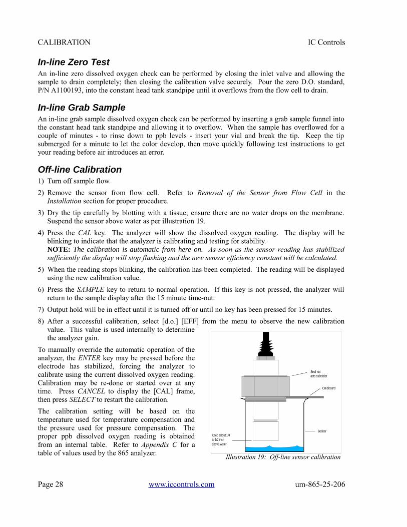
3) Dry the tip carefully by blotting with a tissue; ensure there are no water drops on the membrane.Suspend the sensor above water as per illustration 19.
4) Press the CAL key. The analyzer will show the dissolved oxygen reading. The display will beblinking to indicate that the analyzer is calibrating and testing for stability.NOTE: The calibration is automatic from here on. As soon as the sensor reading has stabilizedsufficiently the display will stop flashing and the new sensor efficiency constant will be calculated.
5) When the reading stops blinking, the calibration has been completed. The reading will be displayedusing the new calibration value.
6) Press the SAMPLE key to return to normal operation. If this key is not pressed, the analyzer willreturn to the sample display after the 15 minute time-out.
7) Output hold will be in effect until it is turned off or until no key has been pressed for 15 minutes.
8) After a successful calibration, select [d.o.] [EFF] from the menu to observe the new calibrationvalue. This value is used internally to determinethe analyzer gain.
To manually override the automatic operation of theanalyzer, the ENTER key may be pressed before theelectrode has stabilized, forcing the analyzer tocalibrate using the current dissolved oxygen reading.Calibration may be re-done or started over at anytime. Press CANCEL to display the [CAL] frame,then press SELECT to restart the calibration.
The calibration setting will be based on thetemperature used for temperature compensation andthe pressure used for pressure compensation. Theproper ppb dissolved oxygen reading is obtainedfrom an internal table. Refer to Appendix C for atable of values used by the 865 analyzer.
Page 28 www.iccontrols.com um-865-25-206
Illustration 19: Off-line sensor calibration
Keep about 1/4to 1/2 inch above water
Beaker
Credit card
Seal nut acts as holder

IC Controls CALIBRATION
Off-line Zero TestThe best way to zero check at the point of use in the plant, is to use zero dissolved oxygen standard,P/N A1100193. Alternatively, a slower approximate zero can be obtained using a solution of sodiumsulfite in water.
Submerge the dissolved oxygen sensor in a deep beaker so that it is 2 inches to 3 inches below thesurface of the zero standard. Provide gentle mixing to ensure the oxygen present is consumed. Thencover the beaker with Parafilm to preserve product integrity. Let stand for five minutes - the sensorshould rapidly fall to low ppb levels, thus confirming operation of the sensor.
Discard used zero standard after use as exposure to air will exhaust it. Reseal the storage bottle tightlyfor the same reason.
Preparation of Sodium Sulfite Solution:
To 1 liter of distilled water add 20 grams of Na2SO3 and mix thoroughly. Ensure that the solution isused within 8 hours because the oxygen scavenger will be used up quickly with exposure to air.
Use of sodium sulfite to get a zero is similar to use described above for zero standard but it may takelonger to get to low ppb levels and/or zero may never be reached.
Calibration ErrorsIf the analyzer detects a problem during calibration, an error message will appear. If an error has beendetected then the calibration was not successful and the previous calibration is retained. Press any keyto acknowledge the error message. Take corrective action and redo the calibration. Consult theTroubleshooting section for further details.
Press any key to resume normal operation after an error message has appeared.
Output HoldThe 865 analyzer allows the user to hold the output for dissolved oxygen. Output hold affects bothoutputs and alarms if and when these monitor the dissolved oxygen input.
Enable output hold by changing the [d.o.] [HOLd] setting to [YES]. Output hold has the followingeffect:
• 4 mA to 20 mA output signals transmitting D.O. are frozen at their current levels.
• Alarms monitoring D.O. will maintain existing on/off condition.
The output hold remains in effect until the operator changes the [d.o.] [HOLd] setting to [no], or untilno key has been pressed for 15 minutes. The 15-minute timeout ensures that output hold for dissolvedoxygen will not remain in effect for longer than 15 minutes if the analyzer is left unattended. If it isdesired to freeze the outputs for longer outages, use standby mode in the main menu.
um-865-25-206 www.iccontrols.com Page 29

CALIBRATION IC Controls
Temperature CompensationAlmost all industrial applications encounter fluctuating temperature and need rapidly respondingautomatic compensation. IC Controls dissolved oxygen sensors typically have a temperaturecompensator (TC) built into the D.O. sensor. The TC is wired to the analyzer allowing the 865 toprovide digital temperature compensation.
If no automatic temperature compensator is available or needed, manual temperature compensation canbe used. If the temperature of the sample is constant, set the manual TC temperature to the processtemperature. If the process temperature varies or is unknown, a default temperature of 25 °C or 77 °F isnormally used.
Selecting Manual Temperature CompensationTo see the current temperature compensation method used by the 865 analyzer during calibration, select[d.o.] [tc] from the menu; refer to illustration 20. Either [Auto] (for automatic temperaturecompensation), or [SEt] (for manual temperature compensation set-point) will be displayed, dependingon the current setting. To change the setting from [Auto] to [SEt], press ENTER to edit the currentsetting. The display will start blinking, indicating that a selection needs to be made. Use the Up orDown arrow key to display [SEt]. Press ENTER to select manual temperature compensation.
With [SEt] still displayed, press SELECT to display and/or adjust the temperature setting to be usedwith manual temperature compensation. If the current value needs to be changed, press ENTER to editthe current setting; the display will start blinking. Use the Up or Down arrow key to display the desiredtemperature for manual temperature compensation. Press ENTER to accept the displayed value.
Barometric Pressure CompensationThe 865 uses a pressure sensor inside the analyzer case to measure the atmospheric pressure. If theatmospheric pressure rises or falls, and/or if the pressure in the analyzer room differs from the localbarometric pressure, the 865 analyzer will automatically read the correct pressure. The 865 will alsocompensate for the correct altitude to give accurate dissolved oxygen partial pressures duringcalibration. While the barometric pressure measurement only affects the 100% saturation reading atcalibration, its use eliminates calibration errors that may cause all readings to be off by as much as 5%or more.
When metric units (the default) areselected, pressure is displayed in kPa.When imperial units are selected, psiare used.
Page 30 www.iccontrols.com um-865-25-206
Illustration 20: Dissolved oxygen menu

IC Controls CALIBRATION
Selecting Manual Pressure CompensationTo see the current pressure compensation method used by the 865 analyzer during calibration, select[d.o.] [Pr.C] from the menu; refer to illustration 20. Either [Auto] (for automatic pressurecompensation), or [SEt] (for manual pressure compensation set-point) will be displayed, depending onthe current setting. To change the setting from [Auto] to [SEt], press ENTER to edit the current setting.The display will start blinking, indicating that a selection needs to be made. Use the Up or Down arrowkey to display [SEt]. Press ENTER to select manual pressure compensation.
With [SEt] displayed, press SELECT to display and/or adjust the pressure setting to be used withmanual pressure compensation. If the current value needs to be changed, press ENTER to edit thecurrent setting; the display will start blinking. Use the Up or Down arrow key to display the desiredpressure for manual pressure compensation. Press ENTER to accept the displayed value.
D.O. Range — Auto or ManualThe 865 dissolved oxygen analyzer is an auto-ranging analyzer. The analyzer has four D.O. inputranges and will automatically switch between them to avoid going off-scale (the output range numbersassociated with the 4 mA to 20 mA output are part of the output module and are independent of theinput ranges described here).
The input range currently being used by the D.O. measuring circuit can be determined by selecting[CONF] [in] [d.o.] [rANG]; refer to illustration 21. If the analyzer is using manual ranging for the D.O.measurement, the user can go into edit mode and switch ranges. If the analyzer is using automaticranging then this setting can be viewed only.
Manual RangingBy default, the analyzer is configured to automatically switch between ranges. The auto switchingcapability can be disabled in the configuration menu by changing the setting of [CONF] [in] [d.o.][AUtO] from [YES] to [no]; refer to illustration 21. Once automatic ranging has been disabled, themeasuring range can be manually selected by changing the setting in [CONF] [in] [d.o.] [rANG]; referto illustration 21.
NOTE: Before starting a calibration, the analyzer needs to use automatic range switching or manualrange [rNG.4] must be selected. Calibrating using manual ranges 1, 2 or 3 will generate error 1.3.
Displayed RangeThe measuring range of the instrument,0 ppb to 10 000 ppb dissolved oxygen, isdetermined by the gain used by theanalyzer itself and the cell current of thedissolved oxygen sensor. The displayedmeasuring range is determined bymultiplying the cell current by theanalyzer range gains.
um-865-25-206 www.iccontrols.com Page 31
Illustration 21: Configuration menu for D.O. input
ERROR MESSAGES IC Controls
ERROR MESSAGESDetected errors and/or cautions are displayed by the analyzer - press the ERROR key or select [Err]from the main menu. If there are no error or caution messages, [NONE] will be displayed, otherwisescroll through the error list using the Up or Down arrow keys. Errors and cautions cannot be removedfrom this list directly; each error or caution will be removed automatically when appropriate, e.g. errorsassociated with improper calibration will be cleared after a successful calibration.
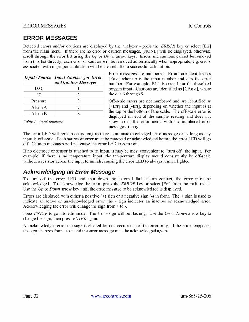
Error messages are numbered. Errors are identified as[En.e] where n is the input number and e is the errornumber. For example, E1.1 is error 1 for the dissolvedoxygen input. Cautions are identified as [CAn.e], wherethe e is 6 through 9.
Off-scale errors are not numbered and are identified as[+Err] and [-Err], depending on whether the input is atthe top or the bottom of the scale. The off-scale error isdisplayed instead of the sample reading and does notshow up in the error menu with the numbered errormessages, if any.
The error LED will remain on as long as there is an unacknowledged error message or as long as anyinput is off-scale. Each source of error must be removed or acknowledged before the error LED will gooff. Caution messages will not cause the error LED to come on.
If no electrode or sensor is attached to an input, it may be most convenient to “turn off” the input. Forexample, if there is no temperature input, the temperature display would consistently be off-scalewithout a resistor across the input terminals, causing the error LED to always remain lighted.
Acknowledging an Error MessageTo turn off the error LED and shut down the external fault alarm contact, the error must beacknowledged. To acknowledge the error, press the ERROR key or select [Err] from the main menu.Use the Up or Down arrow key until the error message to be acknowledged is displayed.
Errors are displayed with either a positive (+) sign or a negative sign (-) in front. The + sign is used toindicate an active or unacknowledged error, the - sign indicates an inactive or acknowledged error.Acknowledging the error will change the sign from + to -.
Press ENTER to go into edit mode. The + or - sign will be flashing. Use the Up or Down arrow key tochange the sign, then press ENTER again.
An acknowledged error message is cleared for one occurrence of the error only. If the error reappears,the sign changes from - to + and the error message must be acknowledged again.
Page 32 www.iccontrols.com um-865-25-206
Input / Source Input Number for Errorand Caution Messages
D.O. 1
°C 2
Pressure 3
Alarm A 7
Alarm B 8
Table 1: Input numbers

IC Controls ERROR MESSAGES
Error Messages for Dissolved Oxygen
um-865-25-206 www.iccontrols.com Page 33
Error Description Causes Solutions
E0.00 No dissolved oxygen measurement.
Open circuit.
Sensor reading is below the low end of range selected.
The sensor is not connected or there isa bad connection.
Manual range switching in effect and analyzer needs to be on a lower range.
E1.1 Electrode has not stabilized after 5 minutesof calibration.
Poor electrode performance; sample D.O., temperature, or pressure is not stable; interference.
Check electrode for proper assembly and redo calibration.
Monitor D.O., temperature and pressure until stable, them redo calibration.
Water drop on membrane - wipe it off,then redo calibration.
E1.2 Electrode efficiency would be greater than 500%. Previous setting retained.
Improper electrode setup, assembly, or electrode failure.
Rip or puncture in membrane.
Recharge and reassemble the sensor, setup sensor, then redo calibration. Refer to Troubleshooting section.
Replace membrane module and redo calibration.
E1.3 Electrode efficiency would be less than 33%. Previous setting retained.
No D.O. signal or, signal from sensor is very weak.
Incorrect membrane module in use.
Black or red discoloring in sensor.
Manual range on low range during calibration.
Check electrode connections, then redo calibration.
Membrane is too thick. Replace membrane module.
Sensor needs service - has seen long exposure to high D.O. levels. Refer to Troubleshooting section.
Change to automatic range switching or change range to range 4.
E1.4 Pressure compensator isoff-scale
Atmosphere outside of pressure operating range of 75 kPa to 130 kPa.
Use manual pressure compensation orrefer to Error Messages for Pressure. Check electronic calibration.
E1.5 Temperature compensator (TC) is off-scale.
Sample outside of TC operating range of -5 °C to 105 °C.
TC not connected.
TC open.
Should not be - D.O. sensor will fail (refer to sample requirements). Use manual temperature compensation or refer to Error Messages for Temperature. Check electronic calibration.
Check TC wiring connections or install TC.
Replace TC (use new D.O. sensor), oruse manual temperature compensation.
ERROR MESSAGES IC Controls
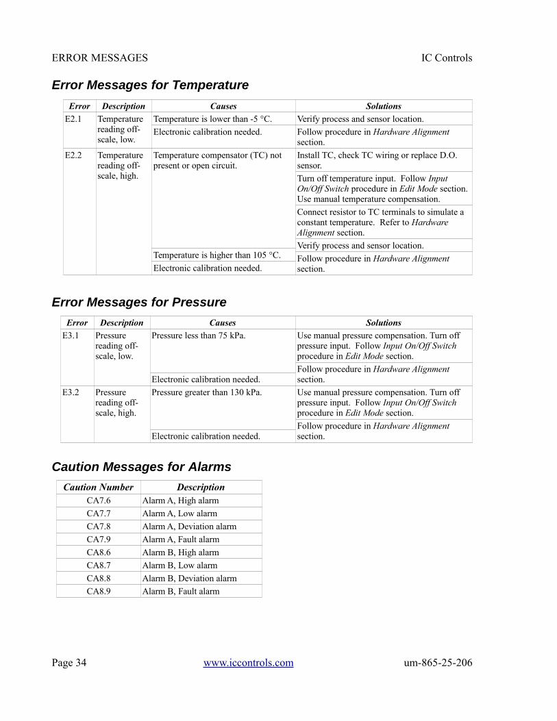
Error Messages for Temperature
Error Messages for Pressure
Caution Messages for Alarms
Page 34 www.iccontrols.com um-865-25-206
Error Description Causes Solutions
E2.1 Temperature reading off-scale, low.
Temperature is lower than -5 °C.
Electronic calibration needed.
Verify process and sensor location.
Follow procedure in Hardware Alignment section.
E2.2 Temperature reading off-scale, high.
Temperature compensator (TC) not present or open circuit.
Temperature is higher than 105 °C.
Electronic calibration needed.
Install TC, check TC wiring or replace D.O. sensor.
Turn off temperature input. Follow Input On/Off Switch procedure in Edit Mode section. Use manual temperature compensation.
Connect resistor to TC terminals to simulate a constant temperature. Refer to Hardware Alignment section.
Verify process and sensor location.
Follow procedure in Hardware Alignment section.
Error Description Causes Solutions
E3.1 Pressure reading off-scale, low.
Pressure less than 75 kPa.
Electronic calibration needed.
Use manual pressure compensation. Turn off pressure input. Follow Input On/Off Switch procedure in Edit Mode section.
Follow procedure in Hardware Alignment section.
E3.2 Pressure reading off-scale, high.
Pressure greater than 130 kPa.
Electronic calibration needed.
Use manual pressure compensation. Turn off pressure input. Follow Input On/Off Switch procedure in Edit Mode section.
Follow procedure in Hardware Alignment section.
Caution Number DescriptionCA7.6 Alarm A, High alarm
CA7.7 Alarm A, Low alarm
CA7.8 Alarm A, Deviation alarm
CA7.9 Alarm A, Fault alarm
CA8.6 Alarm B, High alarm
CA8.7 Alarm B, Low alarm
CA8.8 Alarm B, Deviation alarm
CA8.9 Alarm B, Fault alarm

IC Controls OUTPUT SIGNALS
OUTPUT SIGNALSTwo assignable 4 mA to 20 mA output channels are provided. The user may configure the analyzer todetermine which input signal will be transmitted by each 4 mA to 20 mA output channel. Each outputchannel can be independently configured to transmit the dissolved oxygen, temperature, or pressuresignal. Output 2 can also be used totransmit a range number indication whenoutput 1 is in auto-range mode.
The output channels function independentof each other. Each output channel has aseparate on/off switch and adjustable lowand high span (or scale) adjustments. Thismakes it possible, for example, to transmittwo dissolved oxygen signals, each usingseparate high and low adjustments. Alloutput settings are selected from the [out]menu.
To adjust the output span or outputwindow, set [LO] to correspond to the lowend of the scale or 4 mA output, and set[HI] to correspond to the high end of thescale or 20 mA output. The analyzer willautomatically scale the output accordingto the new settings.
Wiring and CalibrationRefer to illustration 23 and drawing D5940111 for wiring diagram.
The factory output default is 4 mA to 20 mA, however, the outputs can be calibrated for 0 mA to20 mA. For electronic calibration, refer to Calibration of 4 mA to 20 mA Outputs in theTroubleshooting section.
0 VDC to 5 VDC or 1 VDC to5 VDC output can be achieved byplacing a 250 Ω, 1% resistor acrossthe 4 mA to 20 mA output.
The setting in [CONF] [out] [out1]and [out2] can be changed to [0-5],[1-5], [0-20], and [4-20] to agreewith the hardware calibration of theparticular output.
um-865-25-206 www.iccontrols.com Page 35
Illustration 22: Output menu
Illustration 23: Output wiring

OUTPUT SIGNALS IC Controls
Reversing the 4 mA to 20 mA OutputThe low scale setting will normally be lower than the high scale setting. It is possible to reverse theoutput or "flip the window" by reversing the settings of the low and high scale.
Simulated 4 mA to 20 mA OutputSelect [cur] from the menu to display the output current in mA that is presently being transmitted by theoutput signal. The display will be updated as the output signal changes based on the input signal andthe program settings. From here, one can watch the output respond to the change in the input signal.This is useful for verifying program settings and for testing the hardware calibration.
To simulate a different 4 mA to 20 mA output signal press ENTER to access edit mode. Edit thedisplayed mA value to display the desired output needed for testing the output signal. Press ENTER toselect the displayed value. The output signal will be adjusted to put out the desired current. Thisprocess can be repeated as often as necessary.
The output signal is held at the displayed level until the program leaves this part of the menu.
Automatic Range SwitchingAutomatic range switching greatly enhances the resolution capability of the 4 mA to 20 mA output. Atypical application would track the D.O. input from 0 ppb to 20,000 ppb. As soon as the D.O. leveldrops below about 1,000 ppb, a typical recorderwould be able to show very little resolution; referto illustration 24. The alternative of having anoperator change the scale adjustment is impracticalin most cases.
Automatic range switching will automaticallyexpand the span adjustment by a factor of 10 eachtime the output level is within the bottom 10% ofzero. With automatic range switching in effect, theoutput will adjust automatically, moving fromrange 1 which is 0 ppm to 20 ppm down to range 5which is 0 ppb to 2 ppb.
Enabling Output Auto-Range SwitchingNOTE: Only output 1 has automatic range switching available.
From the menu, select [out] [out1] [ArnG], then edit the setting to show [YES].
With automatic range switching for output 1 enabled, the user can see which range output 1 is on byselecting [out] [out1] [rnG] from the menu. This frame gives a live update of the range number. The[rnG] frame can only be selected from the menu if [ArnG] is set to [YES].
Page 36 www.iccontrols.com um-865-25-206
Illustration 24: Output without range switching

IC Controls OUTPUT SIGNALS
Example of Output Auto-Range Switching D.O.
Illustration 25 shows the effect of adding rangeswitching to the 4 mA to 20 mA output - it showsthe 4 mA to 20 mA recovering to stay within 10% to100% of scale by automatically switching betweenranges. Only on the last range, range 5, does the4 mA to 20 mA output fall below 10% of scale.Illustration 24 shows the D.O. level coming downafter a calibration, but has virtually no resolution atthe operating level.
Remote Indication of RangeWhen output 1 is auto-ranging, the user needs toindicate to the recorder, DCS or computer, whichrange it is on. This can be accomplished by usingthe serial output, the alarm contacts or the second4 mA to 20 mA output. The analyzer will allow themethods to be used simultaneously.
To achieve results similar to those in illustration 25, use the following settings:
To use the serial output refer to the Serial Communication section for complete details.NOTE: It may be easier to simply use the serial link digital data all the time and discontinue 4 mA to20 mA auto-range monitoring.
To use the relay contacts for range indication set [AL] [ArnG] to [on].NOTE: If the relays are used for alarms, they cannot be simultaneously used for range indication. The alarm LED, type indication on the display, and serial indications are still active even when the relays are used for range indication.
To use the second 4 mA to 20 mA output for range indication, the following settings must be used forthe selected output.
OUTPUT 1 OUTPUT 2
[in] [d.o.] [in] [ArnG]
[ON.OF] [on] [ON.OF] [on]
[unit] [1E-6] (for ppm) [LO] 1
[HI] 20 [HI] 5
[LO] 0
[ArnG] [YES]
um-865-25-206 www.iccontrols.com Page 37
Illustration 25: Output with range switching
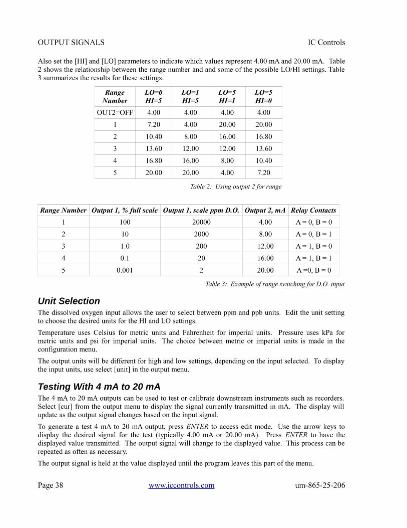
OUTPUT SIGNALS IC Controls
Also set the [HI] and [LO] parameters to indicate which values represent 4.00 mA and 20.00 mA. Table2 shows the relationship between the range number and and some of the possible LO/HI settings. Table3 summarizes the results for these settings.
Range Number Output 1, % full scale Output 1, scale ppm D.O. Output 2, mA Relay Contacts
1 100 20000 4.00 A = 0, B = 0
2 10 2000 8.00 A = 0, B = 1
3 1.0 200 12.00 A = 1, B = 0
4 0.1 20 16.00 A = 1, B = 1
5 0.001 2 20.00 A =0, B = 0
Table 3: Example of range switching for D.O. input
Unit SelectionThe dissolved oxygen input allows the user to select between ppm and ppb units. Edit the unit settingto choose the desired units for the HI and LO settings.
Temperature uses Celsius for metric units and Fahrenheit for imperial units. Pressure uses kPa formetric units and psi for imperial units. The choice between metric or imperial units is made in theconfiguration menu.
The output units will be different for high and low settings, depending on the input selected. To displaythe input units, use select [unit] in the output menu.
Testing With 4 mA to 20 mAThe 4 mA to 20 mA outputs can be used to test or calibrate downstream instruments such as recorders.Select [cur] from the output menu to display the signal currently transmitted in mA. The display willupdate as the output signal changes based on the input signal.
To generate a test 4 mA to 20 mA output, press ENTER to access edit mode. Use the arrow keys todisplay the desired signal for the test (typically 4.00 mA or 20.00 mA). Press ENTER to have thedisplayed value transmitted. The output signal will change to the displayed value. This process can berepeated as often as necessary.
The output signal is held at the value displayed until the program leaves this part of the menu.
Page 38 www.iccontrols.com um-865-25-206
RangeNumber
LO=0HI=5
LO=1HI=5
LO=5HI=1
LO=5HI=0
OUT2=OFF 4.00 4.00 4.00 4.00
1 7.20 4.00 20.00 20.00
2 10.40 8.00 16.00 16.80
3 13.60 12.00 12.00 13.60
4 16.80 16.00 8.00 10.40
5 20.00 20.00 4.00 7.20
Table 2: Using output 2 for range
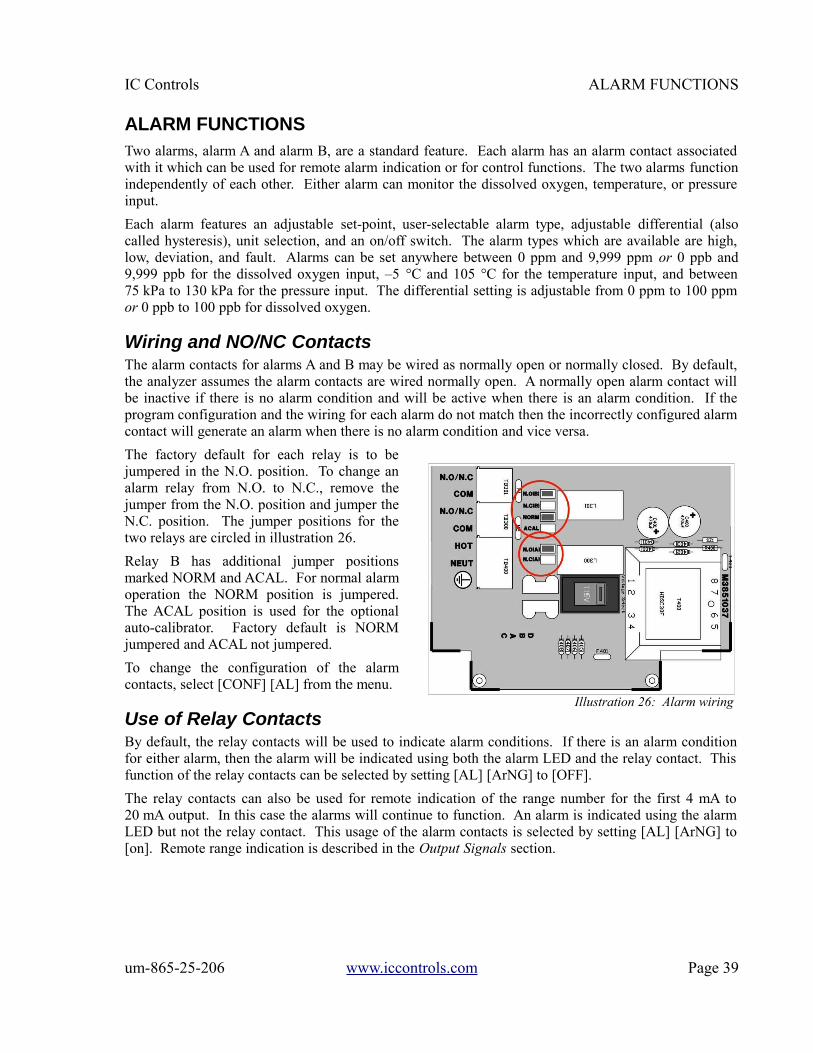
IC Controls ALARM FUNCTIONS
ALARM FUNCTIONSTwo alarms, alarm A and alarm B, are a standard feature. Each alarm has an alarm contact associatedwith it which can be used for remote alarm indication or for control functions. The two alarms functionindependently of each other. Either alarm can monitor the dissolved oxygen, temperature, or pressureinput.
Each alarm features an adjustable set-point, user-selectable alarm type, adjustable differential (alsocalled hysteresis), unit selection, and an on/off switch. The alarm types which are available are high,low, deviation, and fault. Alarms can be set anywhere between 0 ppm and 9,999 ppm or 0 ppb and9,999 ppb for the dissolved oxygen input, –5 °C and 105 °C for the temperature input, and between75 kPa to 130 kPa for the pressure input. The differential setting is adjustable from 0 ppm to 100 ppmor 0 ppb to 100 ppb for dissolved oxygen.
Wiring and NO/NC ContactsThe alarm contacts for alarms A and B may be wired as normally open or normally closed. By default,the analyzer assumes the alarm contacts are wired normally open. A normally open alarm contact willbe inactive if there is no alarm condition and will be active when there is an alarm condition. If theprogram configuration and the wiring for each alarm do not match then the incorrectly configured alarmcontact will generate an alarm when there is no alarm condition and vice versa.
The factory default for each relay is to bejumpered in the N.O. position. To change analarm relay from N.O. to N.C., remove thejumper from the N.O. position and jumper theN.C. position. The jumper positions for thetwo relays are circled in illustration 26.
Relay B has additional jumper positionsmarked NORM and ACAL. For normal alarmoperation the NORM position is jumpered.The ACAL position is used for the optionalauto-calibrator. Factory default is NORMjumpered and ACAL not jumpered.
To change the configuration of the alarmcontacts, select [CONF] [AL] from the menu.
Use of Relay ContactsBy default, the relay contacts will be used to indicate alarm conditions. If there is an alarm conditionfor either alarm, then the alarm will be indicated using both the alarm LED and the relay contact. Thisfunction of the relay contacts can be selected by setting [AL] [ArNG] to [OFF].
The relay contacts can also be used for remote indication of the range number for the first 4 mA to20 mA output. In this case the alarms will continue to function. An alarm is indicated using the alarmLED but not the relay contact. This usage of the alarm contacts is selected by setting [AL] [ArNG] to[on]. Remote range indication is described in the Output Signals section.
um-865-25-206 www.iccontrols.com Page 39
Illustration 26: Alarm wiring

ALARM FUNCTIONS IC Controls
Unit SelectionThe alarm module will be using differentunits for its settings depending on the inputselected and does not necessarily use thesame units as the sample display. Select[unit] from the alarm menu to display theunits in use for an alarm. The [unit] settingaffects the set-point, differential, anddeviation settings for the alarm.
The temperature and pressure inputs willuse different units depending on whethermetric or imperial units are selected. Fortemperature and pressure the unit selectioncan be viewed only. The choice betweenmetric or imperial units is made in theconfiguration menu.
The D.O. input allows the user to selectbetween ppm and ppb units. Edit the unitsetting to choose the desired units foralarm settings.
High or Low AlarmA high alarm is set when the value of the dissolved oxygen, temperature, or pressure rises above the set-point and is cleared when the dissolved oxygen, temperature, or pressure drops to below the set-pointminus the differential (refer to illustration 28). A low alarm is set when the value of the dissolvedoxygen, temperature, or pressure drops below the set-point and is cleared when the dissolved oxygen,temperature, or pressure rises to above the set-point plus the differential (refer to illustration 29). Thedifferential has the effect of setting the sensitivity of the alarm. The differential provides a digitalequivalent of a hysteresis.
Page 40 www.iccontrols.com um-865-25-206
Frequency Operation
Weekly 1. Visual inspection of system.
2. Check flow rate.
Monthly 1. Calibration.
Yearly 1. Replace membrane module.
2. Replace electrolyte.
Table 4: Recommended maintenance schedule
Illustration 27: Alarm menu
Illustration 28: High alarm Illustration 29: Low alarm

IC Controls ALARM FUNCTIONS
Deviation AlarmA deviation alarm is practical when the process is expected to stay within a certain range. An alarm willbe set if the input deviates too far from a set-point. Please note that the [dEv] frame only shows up inthe menu after the alarm function has been changed to deviation alarm, since it would have no effect fora high, low, or fault alarm.
Example:If the dissolved oxygen is expected to stay between 100 ppb and 200 ppb, then we would set [in] to[d.o.], [Func] to [dEv], [SEt] to 150, and [dEv] to 50. Effectively, a high alarm at 200 ppb and a lowalarm at 100 ppb has been set.
The differential setting will continue to function as for high and low alarms.
Fault AlarmA fault alarm for an input will be set when anything goes wrong with that input. Something is wrongwith an input if the input is off-scale or an unacknowledged error message exists for that input. Cautionmessages do not cause a fault alarm.
To use an alarm as a fault alarm, select [FUNC] from the alarm menu, then select [Flt]. To enable thealarm, make sure the on/off switch is set to [on]. Also, set the input in the alarm menu to the desiredinput, either dissolved oxygen, temperature, or pressure.
The set-point and differential for the alarm have no effect when the alarm is used as a fault alarm.
Alarm IndicationIf there is an alarm condition on either alarm A or B, the alarm LED on the front panel will be lightedand the corresponding alarm relay will be set. The error menu will also show a numbered cautionmessage for the alarm, however an alarm caution will not light the error LED. The heading CautionMessages for Alarms in the Error Messages section lists the codes used to indicate alarm conditions. Incase of a fault alarm both the error and alarm LED’s will be lighted.
In addition, an alarm condition for an input will cause the sample display for that input to alternate withthe alarm function display, either [LO], [HI], [dEv], or [FLt]. Press SAMPLE, then use the Up or Downkey to display each of the two samples, if necessary. Each sample frame will first display the samplereading, then after two seconds the alarm type for that input, if any.
Using Alarms for On/Off ControlThe alarms can also be used for process control; the alarm contacts will then function as on/off signalsfor switches controlling a valve, pump, motor, etc. The set-point determines the control point of thesystem and the setting of the differential controls the amount of corrective action before a controlledshut-off occurs. Examples of high and low control using the alarms are shown in the followingillustrations.
um-865-25-206 www.iccontrols.com Page 41
Illustration 31: Low control Illustration 30: High control

CONFIGURATION OF PROGRAM IC Controls
CONFIGURATION OF PROGRAMThe 865 analyzer has been designed with ease-of-use in mind. In most cases the analyzer factoryconfiguration will handle the application and no configuration of the analyzer is necessary.
Relay Contacts; NO/NC
The 865 program by default assumesthe relay contacts are wired normallyopen. A normally open relay contactwill open if there is no alarm and willbe closed by the microprocessorwhen there is an alarm condition. Ifthe program configuration and thewiring do not match the incorrectlyconfigured relay, it will generate analarm when there is no alarm andvice versa.
Metric or Imperial Units
By default the analyzer will usemetric units. This means thattemperature will be displayed usingdegrees Celsius and that the promptfor the temperature input will be[°C]. Using metric units, the pressureis displayed as kPa. The analyzer canalso be made to use imperial units.Using imperial units, temperaturewill be displayed using degreesFahrenheit and the prompt for thefirst temperature input will be [°F];pressure will be displayed as psithroughout the program.
For practical reasons the temperatureinput is always identified as °Cthroughout this instruction manualand in the menus.
To select imperial units for theanalyzer, select [unit] from theconfiguration menu, then go into editmode and change the [°C] prompt to[°F]. Since this is a global setting,both the units used for temperatureand for pressure will change.
Page 42 www.iccontrols.com um-865-25-206
Illustration 32: Configuration menu
IC Controls CONFIGURATION OF PROGRAM
Re-initializing All Settings
Occasionally it may be desirable to reinitialize all of the program settings to bring them back to default.Executing an initialization will cause the analyzer to reset all the program variables and settings tofactory defaults.
Parameters such as the output signal settings, alarm settings, and the program configuration will need tobe re-entered if they were different from the factory default settings.
Select [CONF] [init] [ALL] from the menu. The display will flash [do]. Nothing will happen if youpress CANCEL or SAMPLE. The analyzer will re-initialize only when the user presses ENTER.
Password Security
The factory default is no security. No password security should be necessary if you are the only userand no protection of settings is needed. Password security should be implemented for criticalapplications where program settings may only be changed by authorized personnel.
For minimal security, IC Controls advises that the user set a level 2 password. Leaving the level 1password at “000" gives the operator complete access to all areas of the program but does not allowsettings to be changed in the configuration menu. With minimal security in place, unauthorized usersare prevented from enabling password security.
Appendix A describes how to enable or disable security.
Real-Time Clock
The analyzer maintains an internal date/time clock used for internal date/time stamping of systemevents and the internal data log. Both the system events and the internal data log are accessed using theIC Net™ Intelligence Access Program, which is available as an option.
The model 865 analyzer is equipped with a real-time clock which will maintain the correct time anddate even with the analyzer power turned off.
To set the real-time clock, select [CONF] [ rtc ] from the menu. Set the year, month, date (day of themonth), hour, minute, and second. The [hund] frame displays hundreds of a second but cannot beedited.
A faster way to set the clock in the analyzer is to use the IC Net™ program to synchronize the analyzerwith the connected computer.
Temperature Input Calibration
Refer to the Electronic Hardware Alignment, Alignment of Temperature Input Circuit section for theprocedure on calibrating the temperature input.
Pressure Input Calibration
Refer to the Electronic Hardware Alignment, Alignment of Pressure Input Circuit section for theprocedure on calibrating the pressure input.
um-865-25-206 www.iccontrols.com Page 43
INSTRUMENT MAINTENANCE IC Controls
INSTRUMENT MAINTENANCEThe dissolved oxygen sensors provided by IC Controls are designed for simple maintenance. Thesensors are robust and will withstand difficult applications when properly applied and maintained.Follow instructions in this section to promote proper operation.
NOTE: Galvanic D.O. sensors need a continuous current drain. Maintenance should be done with theD.O. sensor wired to it’s analyzer or with shorted coax center to shield.
Weekly Maintenance1) Check that there are no error indications and displayed concentration reading is reasonable.
2) Inspect unit for leakage.
3) Check that sample flow rate is OK - between 50 mL/min and 200 mL/min.
Monthly MaintenanceCertain applications may require occasional sensor cleaning.
1) Perform a calibration and return sensor to service if response is fast (D.O. measurement returns tolow level in less than 15 minutes) and efficiency stays fairly constant. Refer to Calibration sectionfor complete procedure.
2) If response is slow or a large efficiency change occurs, perform a visual examination of the sensorcell area. If needed, a soft wipe can be used to blot tip, plus detergent and water may be used toremove any deposits.
3) After cleaning, rinse the sensor cell area thoroughly with deionized water.
4) Black or red discoloration may be accompanied by very slow response that does not go away withstandard maintenance. Refer to the Troubleshooting section.
5) Place the electrode back into service and run for one hour prior to calibration. If the response time isstill very slow, check for air bubbles (see Troubleshooting) and remove, or the membrane modulemay require replacement. Follow Yearly Maintenance procedure.
6) Calibrate and return the sensor to service.
Yearly MaintenanceReplace the membrane module and electrolyte as follows.
1) Unscrew the electrode cap and dump the contents.
2) Flush the cell internals with deionized water and examine the lead coils for black or reddiscoloration or heavy gray coating. Such coatings should be removed for best performance(CAUTION: The lead coils are soft metal, never use force in cleaning). Clean light fouling bywiping in the direction of the coils until a shine appears. Heavier fouling may come off with atoothbrush, worked along the coils so the bristles get down in the cracks, followed by rinse andwiping to achieve a dull shine.
3) Remove the old membrane module from the cell and replace with a new one; refer to the Installationsection for complete procedure on Assembly of the Dissolved Oxygen Sensor. Re-assemble the cell,calibrate, check efficiency and if above 50%, return to service.
Page 44 www.iccontrols.com um-865-25-206
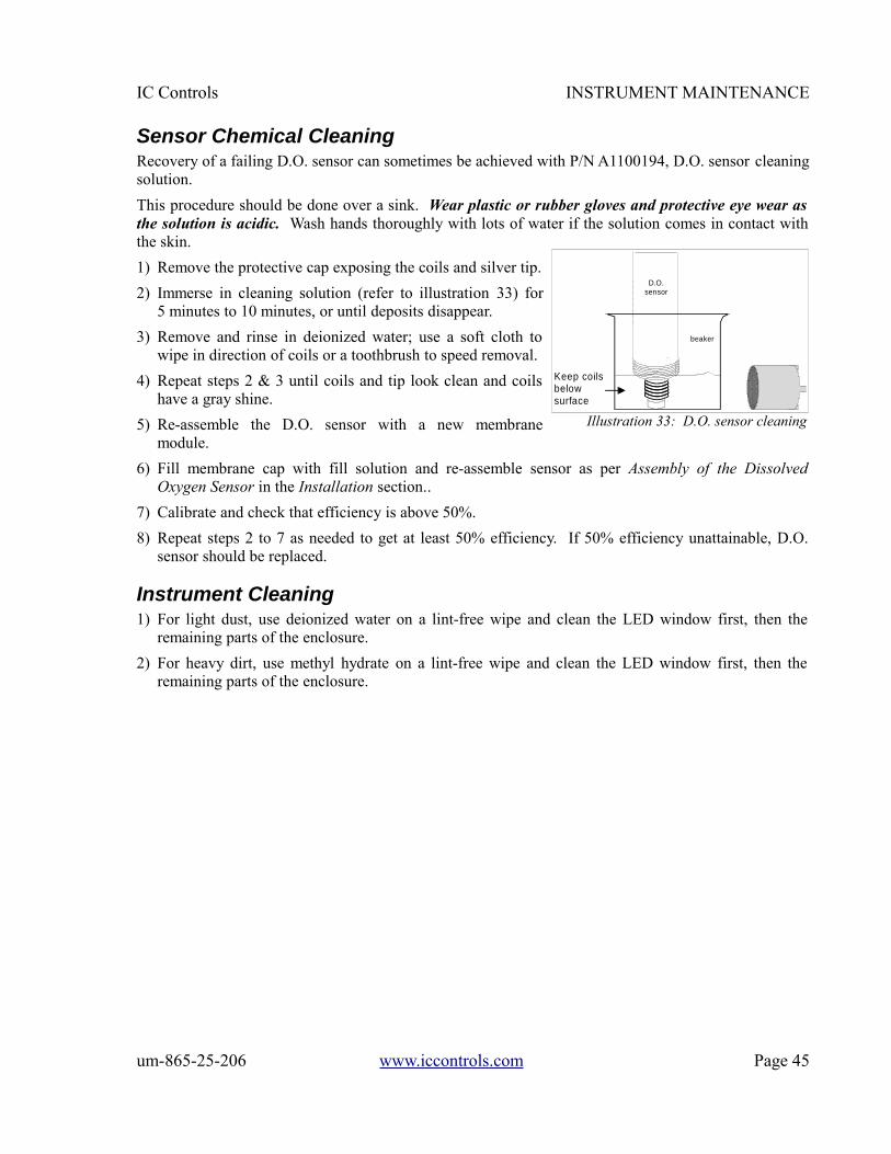
IC Controls INSTRUMENT MAINTENANCE
Sensor Chemical CleaningRecovery of a failing D.O. sensor can sometimes be achieved with P/N A1100194, D.O. sensor cleaningsolution.
This procedure should be done over a sink. Wear plastic or rubber gloves and protective eye wear asthe solution is acidic. Wash hands thoroughly with lots of water if the solution comes in contact withthe skin.
1) Remove the protective cap exposing the coils and silver tip.
2) Immerse in cleaning solution (refer to illustration 33) for5 minutes to 10 minutes, or until deposits disappear.
3) Remove and rinse in deionized water; use a soft cloth towipe in direction of coils or a toothbrush to speed removal.
4) Repeat steps 2 & 3 until coils and tip look clean and coilshave a gray shine.
5) Re-assemble the D.O. sensor with a new membranemodule.
6) Fill membrane cap with fill solution and re-assemble sensor as per Assembly of the DissolvedOxygen Sensor in the Installation section..
7) Calibrate and check that efficiency is above 50%.
8) Repeat steps 2 to 7 as needed to get at least 50% efficiency. If 50% efficiency unattainable, D.O.sensor should be replaced.
Instrument Cleaning1) For light dust, use deionized water on a lint-free wipe and clean the LED window first, then the
remaining parts of the enclosure.
2) For heavy dirt, use methyl hydrate on a lint-free wipe and clean the LED window first, then theremaining parts of the enclosure.
um-865-25-206 www.iccontrols.com Page 45
Illustration 33: D.O. sensor cleaning
Keep coilsbelow surface
beaker
D.O.sensor
TROUBLESHOOTING IC Controls
TROUBLESHOOTINGHigh D.O. ReadingsThe most common problem with low level ppb dissolved oxygen is with air leaks into the sample. Fittings, pressureregulator valves, rotameters, valves and plastic tubing are prone to air leaks. Air leaks can be confirmed byincreasing the sample flow. If the D.O. reading decreases with increased flow and returns when the flow returns, aleak is strongly suspected since more volume dilutes the oxygen leaking in. Some components may trap airbubbles producing a similar flow change but not quite full return, plus will slowly fall toward the low ppb readings.Alleviate the problem by finding and eliminating the leak (or bubble retaining housing).
NOTE: Air contains 20.9% oxygen or in parts per billion, 209,000,000 ppb. Water is saturated with dissolvedoxygen at 8,240 ppb (refer to Appendix B, 25 °C and 101.3 kPa) so air can saturate about 25,000 times as muchwater, or at 1 ppb can add an extra ppb to 25,000,000 times as much sample.
Slow ResponseTypically due to excessive sample line length and low flow, producing long sample transport lags. Resolve byadding a fast-flow loop with the sensor in a short side stream, or by shortening the line. Slow response can also becaused by a buildup of dirt in the sample line which greatly increases the porous surface area that can absorb andrelease oxygen. Resolve by adding a fast-flow loop with the sensor in a short side stream, or by shortening theline. Alternatively, a dirty-water sample system may be needed.
Readings drop fast after calibration but hang up well above expected level, then fall slowlyDue to an air bubble trapped in the sample system. Refer to the heading Tip: How to clear an air bubble, below.
Readings go high or off scale and won’t come down. Also the efficiency goes highTypically an indication of a pinhole or rip in the membrane. Replace the membrane module with a new one.
Readings consistently low or spike lowCharacteristic of wiring problems between the analyzer and the sensor; an open circuit in the field wiring will resultin zero cell current and a reading less than 1 ppb.Also, characteristic of of oxygen consuming bacteria growing on a sample line filter, inside the sample line or eventhe D.O. sensor membrane. Actual D.O. at the sensor is lower. Remove any sample filter and use a dirt bypassarrangement.
Readings gradually fallingThe analyzer can no longer be calibrated properly. This problem is typical of scale or sludge/slime deposits on thesensor face; and/or in the sample line. The sensor and/or line will need to be cleaned. Sample lines can often becleaned with a weak solution of bleach. Refer to the Instrument Maintenance section for sensor cleaningprocedures.
Black or red color in D.O. sensorNot necessarily a problem, especially when seen as orange. Caused by long exposure to air, producing red leadoxide. May go away gradually if left running in a low ppb D.O. sample for several days and the speed of responsewill improve as well.
a) Correct by disassembling the cell and wiping away deposits using a rag or a toothbrush.NOTE: Ensure that you wipe in the direction of the coils to prevent damage to the cell.
b) If cell response remains slow, chemically clean and restore using IC Controls P/N A1100194 dissolved oxygensensor renew solution. Replace the membrane module and return to service.
Readings trend where expected but spike highThis problem is typical of air bubbles in the sample line. If a bubble hangs up in the D.O. flow cell, a high surgethat slowly falls over some hours may be observed. Correct by finding air in-leakage point and stopping leak.
TIP: How to Clear an Air BubbleYou can clear an air bubble stuck in the flow cell by loosening the cell retaining nut, and letting the cell rise up abit, then pressing it back in until it bottoms. Another way to clear an air bubble is to temporarily increase thesample flow. This is easy to do when using a dirt bypass arrangement with a head tank. Simply force the bypassflow through the flow cell by placing a finger over the standpipe in the head tank.
Page 46 www.iccontrols.com um-865-25-206

IC Controls ELECTRONIC HARDWARE ALIGNMENT
ELECTRONIC HARDWARE ALIGNMENTAlignment of Dissolved Oxygen Detection Circuit
1. Set up a precision multimeter, Fluke 8051A or equivalent, to read VDC.
2. Use the “D.O.+” sensor connections, TB200-1, and “D.O.-” sensor, TB200-3, as common. Refer towiring diagram, D5920101.
3. Place analyzer on manual range selection by selecting [CONF] [in] [d.o.] [Auto] from the menu andediting the setting to read [no].
4. Set the D.O. input range to range 4 by selecting [CONF] [in] [d.o.] [rANG] from the menu andediting the setting to read [rNG.4].
5. Set the D.O. efficiency constant to 100% by selecting [d.o.] [EFF] from the menu and editing thevalue to read 100.0%.
6. Adjust the electronic standardize with blue trimpot VR200, located mid-board above the D.O.terminal block. Adjust the trimpot to a reading of 2.50 V at TP201 while inputing 0.120 VDCthrough a 10K 1% resistor. 0.120 VDC simulates 8,240 ppb D.O. at approximately 100 % efficiencyunder the above conditions.
7. Return analyzer to automatic range selection by selecting [CONF] [in] [d.o.] [Auto] from the menuand editing the setting to read [YES].
Alignment of Temperature Input Circuit
The temperature input can be adjusted both by making electronic adjustments and/or by having the programcompensate for differences in offset. Both procedures are described below.
Adjusting Electronic Calibration
1. Remove any offset calculated by a previous software calibration of the temperature input. Select [CONF][in] [°C] [OFFS] from the menu and edit the offset to read 0.0.
2. Set up a precision multimeter, Fluke 8051A or equivalent, to read VDC.
3. Use the "- TEMP" sensor connection; TB201-2, as common. Place a 100 1% resistor across T+ and T-terminals. Adjust blue trimpot VR201 for a reading of 0.200 V at TP202. Refer to drawing D5940111 forcomponent locations.
4. Place a 138.5 1% resistor across T+ and T- terminals. Adjust blue trimpot VR202 for a reading of4.85 V at TP202. Refer to drawing D5940111 for component locations.
5. Close the case and press SAMPLE followed by the Down arrow key to display the temperature reading.
6. Re-insert the 100 1% resistor and adjust VR201 until the display reads 0.0 °C ± 0.1 °C.
7. Re-insert the 138.5 1% resistor and adjust VR202 until the display reads 100.0 °C ± 0.1 °C.
Software Calibration
To do a software calibration of the temperature input, the correct temperature needs to be known.
1. Select [CONF] [in] [°C] [CAL] from the menu. The actual temperature as measured by the temperaturesensor will be displayed. Edit the displayed value to the known correct temperature. Press ENTER toleave edit mode, then SELECT to start the calibration.
2. The current temperature will be shown using a flashing display. When the input appears to be stable,press ENTER to set the new temperature. The software offset for the temperature input will be adjustedautomatically.
um-865-25-206 www.iccontrols.com Page 47

ELECTRONIC HARDWARE ALIGNMENT IC Controls
3. The calculated offset in degrees Celsius can be viewed by selecting [CONF] [in] [°C] [OFFS] from themenu. Whenever the hardware alignment is ‘correct’, the offset will be 0.0. The displayed offset can beedited.
Alignment of Pressure Input Circuit
The pressure input can be adjusted both by making electronic adjustments and/or by having the programcompensate for differences in offset. Both procedures are described below.
Adjusting Electronic Calibration
1. Obtain the current barometric pressure from your local weather station or from a barometer.
2. Remove any offset calculated by a previous software calibration of the temperature input. Select[CONF] [in] [PrES] [OFFS] from the menu and edit the offset to read 0.0.
3. Set up a precision multimeter, Fluke 8051A or equivalent, to read VDC.
4. Use the “TEMP-” sensor connection, TB201-2, as common. See wiring diagram D5920101. Adjustblue trimpot VR203, located at top of board, for a reading of 2.50 V at TP204.
5. Close the case and press the SAMPLE key followed by the Down arrow key twice to display thepressure reading. Reading should be within 0.1 kPa of the pressure obtained in step 1.
Software Calibration
1. Obtain the current barometric pressure from your local weather station or from a barometer.
2. Select [CONF][in] [PrES] [CAL] from the menu. The actual pressure as measured by the pressuresensor will be shown. Edit the displayed value to the known, correct pressure. Press ENTER toleave edit mode, then SELECT to start the calibration.
3. The current pressure will be shown using a flashing display. When it looks like the input is stable,press ENTER to set the new pressure. The software offset for the pressure input will be adjustedautomatically.
4. The calculated offset in kPa can be viewed by selecting [CONF] [in] [PrES] [OFFS] from the menu.
Calibration of 4 mA to 20 mA Outputs
Use one of the following two approaches to get the analyzer to output the desired current level, and thenmake electronic adjustments to calibrate the output.
Approach 1: Simulated 4 mA to 20 mA Output (Self Calibration)
1. Select [cur] from the output 1 menu to display the present output current in mA. The display will beupdated as the output current changes based on the input signal and the program settings.
2. To simulate a different 4 mA to 20 mA output signal, press ENTER to enter edit mode. Use thearrow keys to display the desired output needed for testing the output signal. Press ENTER to selectthe displayed value. The output signal will be adjusted to put out the desired current. This processcan be repeated as often as necessary to output different signal levels.
3. The output signal is held at the displayed level until the program leaves this menu selection. Makecalibration adjustments while the analyzer shows the output at 20.00 mA.
4. Repeat the above steps for output 2.
Page 48 www.iccontrols.com um-865-25-206
IC Controls ELECTRONIC HARDWARE ALIGNMENT
Approach 2: Use Voltage Source to Adjust Input
This faster calibration approach requires a voltage source for the input.
1. To calibrate output 1, set [in] = [°C]. Input a low enough signal to cause analyzer to indicate [- Err];the analyzer will output 4.00 mA. Reverse the polarity or input a high enough signal to cause theanalyzer to indicate [+ Err] ; the analyzer will output 20.00 mA.
2. Repeat step 1 for output 2.TIP: Both outputs can be simultaneously calibrated if you set [in] = [°C] for both inputs.
3. Be sure to return the inputs back to the desired parameters to be transmitted. Typically D.O. foroutput 1 and temperature for output 2.
Adjusting 4 mA to 20 mA Electronic Calibration
1. The outputs are isolated from the main circuit, therefore, measurements are made with common atthe output 2 terminal, TB304, '-' terminal.
2. Measure output 1 ‘zero’ at TP301 (pin 8 of U304) while output 1 is outputting 4.00 mA. Thereading should be between -0.870 V and -0.890 V. Adjust #2 voltage with VR300.
3. Change analyzer output to 20.00 mA; switch multimeter to mA and measure '+' terminal of output 1,and adjust VR301 so that the current reads 20.00 mA. Return analyzer output to 4.00 mA and trimactual output to 4.00 mA using VR300. Check again at 20.00 mA and repeat adjustments untilsatisfied.
4. Measure output 2 'zero' at TP300 (pin 7 of U304) while output 2 is outputting 4.00 mA. The testpoint should read between -0.870 V and -0.890 V. Adjust #2 ‘zero’ voltage with VR302.
5. Change output at output 2 to 20.00 mA; switch multimeter to mA and measure '+' terminal of output2, at TB304, and adjust VR303 (span pot) until the current reads 20.00 mA.NOTE: Zero and span are very wide range adjustments which show small interactions. Recheckzero and span to confirm good calibration.
6. If so desired, all software settings can be returned to factory default condition by following theprocedure in Configuration of Program; Re-initializing All Settings.
Testing Relay Outputs
1. Relay output operation can be verified by testing for contact closure or continuity at each relay. Toactivate a relay, select [CONF] [NO.NC] [AL.A] from the menu. Press ENTER to go into edit mode,then press the Up or Down arrow key to change the normally open/normally closed configurationfrom open to closed. Press ENTER to accept the new value. A closed contact should open and anopen contact should close.
2. Repeat step 1 for the Alarm B contact.
3. If so desired, all software settings can be returned to factory default condition by following theprocedure in Configuration of Program; Re-initializing All Settings.
um-865-25-206 www.iccontrols.com Page 49
DISPLAY PROMPTS IC Controls
DISPLAY PROMPTS[0-5] Use 0 VDC to 5 VDC configuration for output.[0-20] Use 0 mA to 20 mA configuration for output.[1-5] Use 1 VDC to 5 VDC configuration for output.[1E-6] dissolved oxygen units in parts per million, ppm; unit selection in scientific notation.[4-20] Use 4 mA to 20 mA configuration for output.[5VDC] Diagnostic to display 0 VDC to 5 VDC raw input voltage for D.O. input. [ACC.n] Access level for security. Displayed after password entered by user.[AL] Alarms.[AL.A] Alarm A.[AL.b] Alarm B.[ArnG] Automatic range switching for 4 mA to 20 mA output.[ASCI] ASCII serial output log.[Auto] Automatic.[BAud] Baud rate for serial communications.[°C] Temperature in degrees Celsius; use metric units.[CAL] Calibrate analyzer.[CHIP] Chip: Is this analyzer equipped with a real-time clock chip?[CLr] Clear the internal data log.[cnt] Count of number of readings in internal data log.[CLSd] Normally closed alarm contact.[CONF] Configuration of program menu.[Cont] Continue internal data log when buffer full.[cur] Signal output in mA, or current.[dAtE] Date: Real-time clock setting for day of the month.[dEv] Deviation alarm.[diff] Differential for alarm settings.[dLAY] Alarm activation delay.[d.o.] Dissolved oxygen input.[do] Do: press ENTER to execute the reset/clear action.[donE] Done: reset/clear action has been taken.[EFF] D.O. cell efficiency constant; adjusted via calibration.[Err] Error or warning number.[Er.94] RAM checksum failed. Some settings may be lost.[°F] Temperature in degrees Fahrenheit; use imperial units.[FLt] Fault alarm.[FrEq] Frequency of internal data log updates in seconds.[FULL] Full: What to do when internal data log is full; continue or stop.[Func] Function, alarm type.[HI] High alarm; high limit (20 mA) for 4 mA to 20 mA output window.[Hold] Output hold during calibration.[hour] Hour: Real-time clock setting.[hund] Hundredth of a second: Real-time clock display.[iLOG] Internal data log.[in] Input OR Minute: real-time clock setting.[kPa] kPa units for pressure.[LO] Low alarm; low limit (4 mA) for 4 mA to 20 mA output window.[NodE] Node number for IC Net communications.
Page 50 www.iccontrols.com um-865-25-206

IC Controls DISPLAY PROMPTS
DISPLAY PROMPTS CON'T[NO.NC] Normally open/Normally closed.[OFF] Off.[OFFS] Offset.[on] On.[ON.OF] On/off switch.[onth] Month: Real-time clock setting.[OPEN] Normally open alarm contact.[out] Output menu.[out 1] First 4 mA to 20 mA analog output channel.[out 2] Second 4 mA to 20 mA analog output channel.[PAS.1] Set password 1, operator access.[PAS.2] Set password 2, complete access.[PASS] Enter password to change access level.[ppb] Parts per billion D.O. unit selection.[Pr.C] Pressure compensation setting.[PSI] psi units for pressure.[rANG] Analyzer dissolved oxygen input range selection.[rnG] Range number.[rtc] Real-time clock.[SEC] Seconds: Real-time clock setting.[SEr] Serial communications menu.[SEt] Set-point: Select manual compensation.[StAr] Start internal data log.[StbY] Standby mode for analyzer.[StOP] Stop internal data log.[t.c.] Temperature compensation setting.[unit] Display/setting of units.[YEAr] Year: Real-time clock setting.
um-865-25-206 www.iccontrols.com Page 51

GLOSSARY IC Controls
GLOSSARYD.O. Dissolved oxygen.
EPROM Erasable Programmable Read Only Memory. The EPROM chip holds the program which determines thefunctioning of the 855 analyzer. Replacing the EPROM chip with a chip containing a new or an updated programchanges the way the analyzer functions. The EPROM chip is programmed by the manufacturer.
Hysteresis the reading at which an alarm is turned on is not the same reading at which the alarm is turned offagain. This phenomenon is referred to as the hysteresis.
LED Light Emitting Diode. LEDs are used as on/off indicators on the front panel of the 855.
Menu the series of prompts which determine the layout of the program used by the analyzer.
Microprocessor an integrated circuit (chip) which executes the program on the EPROM chip and controls allthe input/output functions.
NC Normally closed
NO Normally open
Normally closed each of the alarm contacts can be wired and configured as normally open or normally closed.A circuit which is wired normally closed will be closed (i.e. the external device wired to it is turned on) when theanalyzer is not powered.
Normally open a circuit which is wired normally open will be open (i.e. the external device wired to it isturned off) when the analyzer is not powered.
ppb Concentration as parts per billion.
ppm Concentration as parts per million.
RAM Random Access Memory. Memory in a RAM chip can be both written to and read from. The contents ofRAM will disappear as soon as the RAM chip loses power. The RAM chip has a battery backup device whichpreserves the contents of the RAM chip for a considerable time even if the analyzer is turned off. All settings arestored in RAM.
TC Temperature compensator
Temperature compensation correction for the influence of temperature on the sensing electrode. The analyzerreads out concentration as if the process were at 25 °C or 77 °F, regardless of actual solution temperature.
Page 52 www.iccontrols.com um-865-25-206

IC Controls Appendix A — Security
Appendix A — SecurityThe analyzer has a built-in password protection system. This security system is disabled by default anddoes not need to be enabled if no password protection isnecessary. If you choose not to enable the passwordprotection system then the user will have unrestrictedaccess to all analyzer settings available through themenu as described in this manual.
Having security disabled gives the user the same accessto the program as being at access-level 2 at all times.
With security enabled anyone can view settingsanywhere in the program. When you do not haveproper access rights, the program will display [PASS]for 2 seconds, indicating that a proper password mustbe entered before being allowed to proceed.
This appendix contains instructions for settingpasswords in the configuration section of the menu.Daily usage of the analyzer by the operator does notrequire knowledge of setting passwords in theconfiguration section since all passwords are entered byselecting [PASS] directly from the main menu.
ENTERING A PASSWORD
With security enabled, select [PASS] from the main menu. The analyzer will display [0000]. Use thearrow keys to display your level 1 or level 2 password, then press ENTER. The program will display[good], followed by your access level before returning to the main menu. If an incorrect password wasentered, the program displays [bAd] instead. Refer to illustration 34 to determine how the programvalidates a password.
You will now have level 1 or level 2 access for as long as you are working with the analyzer. Theaccess level will automatically be restored to level 0 after no key has been pressed for 15 minutes. This15-minute timeout will also return to display the main sample.
It is good practice to return the analyzer to level 0 access (or level 1 access if password 1 is set to“000”) when you have finished using the analyzer. This is accomplished by selecting [PASS] from themain menu, then pressing ENTER with [0000] displayed.
ENABLING PASSWORD SECURITY
When security is disabled, both password 1 and password 2 are set to “0000.” Security is enabled bysetting password 2 to a non-zero value.
Level 2
Select [CONF] [PAS.2] from the menu. The analyzer will display [0000]. Use the arrow keys tochange the display to the desired password for level 2. You can press SAMPLE at any time to safelycancel password entry. Press ENTER to enter the password into memory and to enable passwordsecurity. The analyzer program automatically returns to the configuration menu.
With only password 2 set to a non-zero value, level 2 access is required to make changes in theconfiguration menu but all other settings are unprotected. Effectively the user will always have at leastlevel 1 access.
um-865-25-206 www.iccontrols.com Page 53
access level description
0
View-only access.Usage: operator and for information-only.
1
Access to editable settings (calibration, setpoint, span, etc.) except for configuration menu.Usage: calibration and technical adjustments.
2
Master access to all settings.Usage: configuration of analyzer, installation, management. Passwords can be changed.
Table 5: Access levels

Appendix A — Security IC Controls
Level 1
At this point, password 1 is still “000.” You may optionally enable operator access control or level 1security by changing the level 1 password from “000" to a non-zero value. Change the password byselecting [CONF] [PAS.1] from the menu, then entering an appropriate 3-digit password.
RECORDING YOUR PASSWORDS
You may want to write down the passwords you set and store them in a secure place. Once a passwordhas been set, there is no way to redisplay it. Since passwords are set in the configuration menu, level 2access is required to change either password. If you have forgotten the level 2 password, there is nosimple way to regain access to the analyzer. Contact the factory if you find yourself locked out of theanalyzer.
DISABLING PASSWORD SECURITY
Password security can be disabled by setting the level 2 password to “0000.” In order to change thepassword you must first have level 2 access to the program.
Select [CONF] [PAS.2] from the menu, then press ENTER when the program displays [0000]. Bothpasswords 1 and 2 are set to “0000" and security is now disabled. The main menu will be changed toexclude the [PASS] frame , and the configuration menu will no longer have the [PAS.1] frame.
Page 54 www.iccontrols.com um-865-25-206
Illustration 34: Password validation
IC Controls Appendix A — Security
PASSWORD EXAMPLE - A QUICK TOUR
With security disabled, select [CONF] [PAS.2] from the menu. Set the level 2 password to “0002".Select [CONF] [PAS.1] from the menu. Set the level 1 password to ”001." Security is now enabled.
Select [PASS] from the main menu. Press ENTER with [0000] displayed. The analyzer will display[ACC.0] to indicate we are now at access level 0.
Try changing the output 1 low setting. Select [out] [out1] [LO] from the menu. The current value willdisplay. Press ENTER to go into edit mode. The analyzer will display [PASS] for 2 seconds because weneed to enter a password first. Level 1 security is needed to change this setting.
Select [PASS] from the main menu again. Change the displayed value to [0001], which is the level 1password. Press ENTER. The analyzer will display [good], followed by [ACC.1], indicating that thepassword is valid and that we now have level 1 access.
Try changing the output 1 low setting again. You will find that this time we can go into edit modeunhindered.
Select [PASS] from the main menu again. Enter the level 2 password, which is “0002.” We are goingto set the level 2 password to “0000” again to disable password security. Password 2 is found in theconfiguration menu and therefore requires level 2 access before it can be accessed. Select [CONF][PAS.2] from the menu. Press ENTER with [0000] displayed. Both passwords are set to “0000” againand password security is disabled.
um-865-25-206 www.iccontrols.com Page 55

Appendix B — Unit Conversion IC Controls
Appendix B — Unit Conversion
Dissolved Oxygen Units
ppm= parts per million
ppb= parts per billion
ppt= parts per trillion
1 ppm=1000 ppb
1 ppb=0.001 ppm
1 ppb=1000 ppt
1 ppm is approximately 1 mg/L. Some variation occurs because the weight of water varies slightly withtemperature.
Percent saturation is directly related to the temperature and pressure of the system. A given ppb readingwill give a different percent saturation depending on the variation in temperature and pressure. Refer toAppendix C for a table of saturated D.O. values.
Temperature Units
° C=59(° F−32)
° F=(95
° C )+32
Pressure Units
1 kPa=0.145 psi
1 psi=6.895 kPa
1atmosphere=1.01325bar
1atmosphere=760 mm Hg
1atmosphere=14.70 psi
1atmosphere=101.3 kPa
1bar=100 kPa
Page 56 www.iccontrols.com um-865-25-206
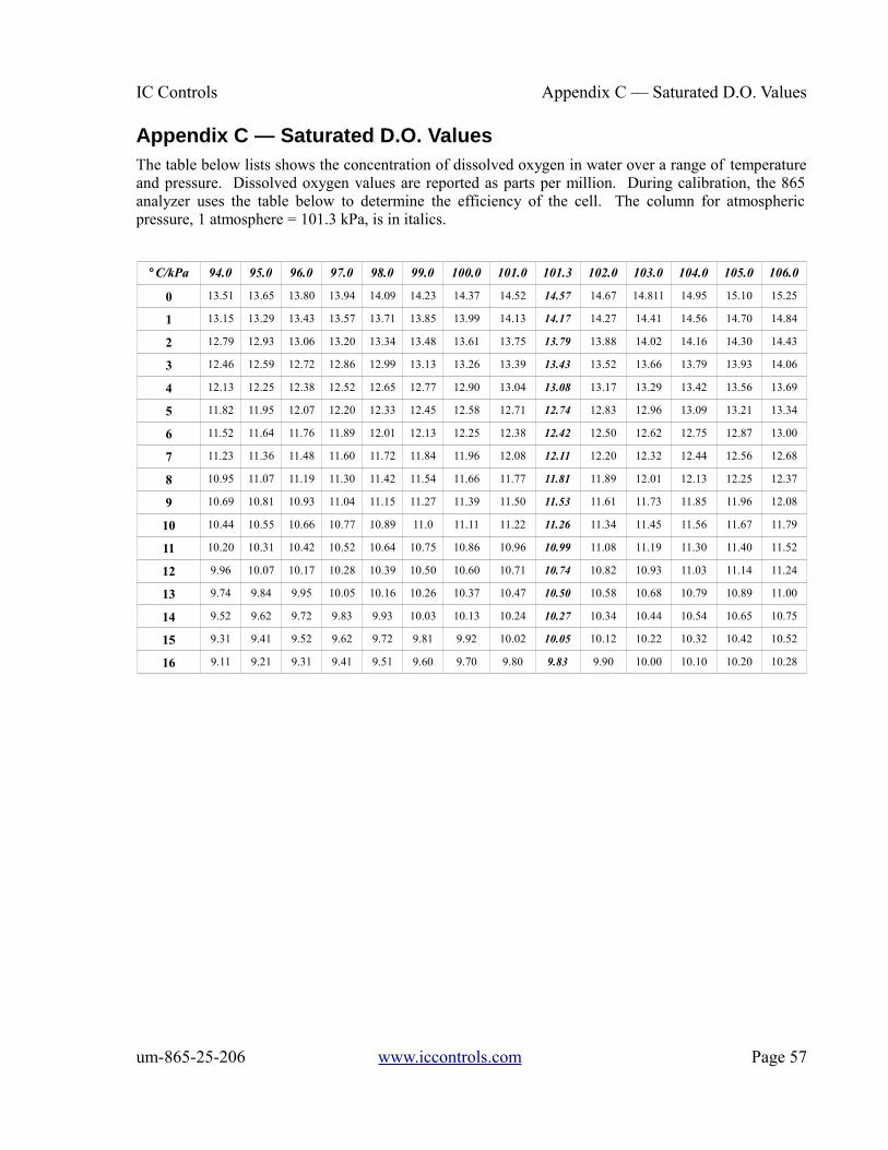
IC Controls Appendix C — Saturated D.O. Values
Appendix C — Saturated D.O. ValuesThe table below lists shows the concentration of dissolved oxygen in water over a range of temperatureand pressure. Dissolved oxygen values are reported as parts per million. During calibration, the 865analyzer uses the table below to determine the efficiency of the cell. The column for atmosphericpressure, 1 atmosphere = 101.3 kPa, is in italics.
°C/kPa 94.0 95.0 96.0 97.0 98.0 99.0 100.0 101.0 101.3 102.0 103.0 104.0 105.0 106.0
0 13.51 13.65 13.80 13.94 14.09 14.23 14.37 14.52 14.57 14.67 14.811 14.95 15.10 15.25
1 13.15 13.29 13.43 13.57 13.71 13.85 13.99 14.13 14.17 14.27 14.41 14.56 14.70 14.84
2 12.79 12.93 13.06 13.20 13.34 13.48 13.61 13.75 13.79 13.88 14.02 14.16 14.30 14.43
3 12.46 12.59 12.72 12.86 12.99 13.13 13.26 13.39 13.43 13.52 13.66 13.79 13.93 14.06
4 12.13 12.25 12.38 12.52 12.65 12.77 12.90 13.04 13.08 13.17 13.29 13.42 13.56 13.69
5 11.82 11.95 12.07 12.20 12.33 12.45 12.58 12.71 12.74 12.83 12.96 13.09 13.21 13.34
6 11.52 11.64 11.76 11.89 12.01 12.13 12.25 12.38 12.42 12.50 12.62 12.75 12.87 13.00
7 11.23 11.36 11.48 11.60 11.72 11.84 11.96 12.08 12.11 12.20 12.32 12.44 12.56 12.68
8 10.95 11.07 11.19 11.30 11.42 11.54 11.66 11.77 11.81 11.89 12.01 12.13 12.25 12.37
9 10.69 10.81 10.93 11.04 11.15 11.27 11.39 11.50 11.53 11.61 11.73 11.85 11.96 12.08
10 10.44 10.55 10.66 10.77 10.89 11.0 11.11 11.22 11.26 11.34 11.45 11.56 11.67 11.79
11 10.20 10.31 10.42 10.52 10.64 10.75 10.86 10.96 10.99 11.08 11.19 11.30 11.40 11.52
12 9.96 10.07 10.17 10.28 10.39 10.50 10.60 10.71 10.74 10.82 10.93 11.03 11.14 11.24
13 9.74 9.84 9.95 10.05 10.16 10.26 10.37 10.47 10.50 10.58 10.68 10.79 10.89 11.00
14 9.52 9.62 9.72 9.83 9.93 10.03 10.13 10.24 10.27 10.34 10.44 10.54 10.65 10.75
15 9.31 9.41 9.52 9.62 9.72 9.81 9.92 10.02 10.05 10.12 10.22 10.32 10.42 10.52
16 9.11 9.21 9.31 9.41 9.51 9.60 9.70 9.80 9.83 9.90 10.00 10.10 10.20 10.28
um-865-25-206 www.iccontrols.com Page 57
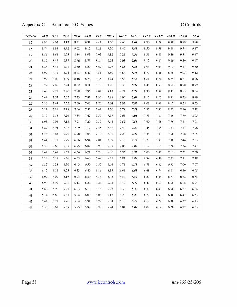
Appendix C — Saturated D.O. Values IC Controls
°C/kPa 94.0 95.0 96.0 97.0 98.0 99.0 100.0 101.0 101.3 102.0 103.0 104.0 105.0 106.0
17 8.92 9.02 9.12 9.21 9.31 9.41 9.50 9.60 9.63 9.70 9.79 9.89 9.99 10.08
18 8.74 8.83 8.92 9.02 9.12 9.21 9.30 9.40 9.43 9.50 9.59 9.68 9.78 9.87
19 8.56 8.66 8.75 8.84 8.93 9.03 9.12 9.21 9.24 9.31 9.40 9.49 9.58 9.67
20 8.39 8.48 8.57 8.66 8.75 8.84 8.93 9.03 9.06 9.12 9.21 9.30 9.39 9.47
21 8.23 8.32 8.41 8.50 8.59 8.67 8.76 8.85 8.88 8.95 9.04 9.13 9.21 9.30
22 8.07 8.15 8.24 8.33 8.42 8.51 8.59 8.68 8.71 8.77 8.86 8.95 9.03 9.12
23 7.92 8.00 8.09 8.18 8.26 8.35 8.44 8.52 8.55 8.61 8.70 8.79 8.87 8.96
24 7.77 7.85 7.94 8.02 8.11 8.19 8.28 8.36 8.39 8.45 8.53 8.62 8.70 8.79
25 7.63 7.71 7.80 7.88 7.96 8.04 8.13 8.21 8.24 8.30 8.38 8.47 8.55 8.64
26 7.49 7.57 7.65 7.73 7.82 7.90 7.98 8.06 8.09 8.15 8.23 8.31 8.39 8.48
27 7.36 7.44 7.52 7.60 7.68 7.76 7.84 7.92 7.95 8.01 8.09 8.17 8.25 8.33
28 7.23 7.31 7.38 7.46 7.55 7.63 7.70 7.78 7.81 7.87 7.95 8.02 8.10 8.18
29 7.10 7.18 7.26 7.34 7.42 7.50 7.57 7.65 7.68 7.73 7.81 7.89 7.79 8.05
30 6.98 7.06 7.13 7.21 7.29 7.37 7.44 7.52 7.55 7.60 7.68 7.76 7.84 7.91
31 6.87 6.94 7.02 7.09 7.17 7.25 7.32 7.40 7.42 7.48 7.55 7.63 7.71 7.78
32 6.75 6.83 6.90 6.98 7.05 7.13 7.20 7.28 7.30 7.35 7.43 7.50 7.58 7.65
33 6.64 6.71 6.79 6.86 6.94 7.01 7.09 7.16 7.18 7.23 7.31 7.38 7.46 7.53
34 6.53 6.60 6.67 6.75 6.82 6.90 6.97 7.05 7.07 7.12 7.19 7.26 7.34 7.41
35 6.42 6.49 6.57 6.64 6.71 6.79 6.86 6.93 6.95 7.00 7.07 7.15 7.22 7.30
36 6.32 6.39 6.46 6.53 6.60 6.68 6.75 6.83 6.84 6.89 6.96 7.03 7.11 7.18
37 6.22 6.28 6.36 6.43 6.50 6.57 6.64 6.71 6.73 6.78 6.85 6.92 7.00 7.07
38 6.12 6.18 6.25 6.33 6.40 6.46 6.53 6.61 6.63 6.68 6.74 6.81 6.89 6.95
39 6.02 6.09 6.16 6.23 6.30 6.36 6.43 6.50 6.52 6.57 6.64 6.71 6.78 6.85
40 5.93 5.99 6.06 6.13 6.20 6.26 6.33 6.40 6.42 6.47 6.53 6.60 6.68 6.74
41 5.83 5.90 5.97 6.03 6.10 6.16 6.23 6.30 6.32 6.37 6.43 6.50 6.57 6.64
42 5.74 5.80 5.87 5.94 6.00 6.06 6.13 6.20 6.22 6.27 6.33 6.40 6.47 6.53
43 5.64 5.71 5.78 5.84 5.91 5.97 6.04 6.10 6.13 6.17 6.24 6.30 6.37 6.43
44 5.55 5.61 5.68 5.75 5.82 5.88 5.94 6.01 6.03 6.08 6.14 6.20 6.27 6.33
Page 58 www.iccontrols.com um-865-25-206

IC Controls Appendix D — Default Settings
Appendix D — Default SettingsThe following program settings are the default settings for the analyzer. New analyzers will have thesesettings unless the setup has already been customized for your application.
Outputs
Output 1 Output 2
Input to be transmitted dissolved oxygen temperature
Low setting 0.00 0.0
High setting 100 100.0
ON/OFF switch ON ON
Units ppb ° C
Automatic range indication OFF -
Alarms
Alarm A Alarm B
Input for alarm dissolved oxygen dissolved oxygen
Alarm function High High
ON/OFF switch OFF OFF
Set-point 10.0 100
Differential 1.0 1.0
Units ppb ppb
Global units, metric units:temperature degrees Celsiuspressure kPadissolved oxygen concentration ppb (parts per billion)
Alarm contactsConfigured normally open.
SecurityNot enabled.
Temperature compensationAutomatic TC using temperature input.
Pressure compensation Automatic pressure compensation using pressure input.
Input on/off configurationThe temperature input is on and will show up in the sample menu.
um-865-25-206 www.iccontrols.com Page 59

Appendix E — Parts List IC Controls
Appendix E — Parts List
Part Number Description Drawing #
865 Dissolved Oxygen Analyzer
A9051027 Assembly, 865 D.O. power PCB D5940111
A9051028 Assembly, 865 display board
A9101012 Circuit breaker switch, 0.25 A
A9141012 Assembly, 865 case, complete with keypad D5970171
A9201015 18 position, inter-board connector
865-25 Sample Conditioning Panel
A2103004 ppb stainless steel flow cell
A3010009 Teflon ferrule for ppb flow cell, P/N A21030004
A7201113 Stainless steel nut for ppb flow cell, P/N A21030004
A7201490 Stainless steel inlet fittings and O-ring
A9551054 O-ring for inlet fitting
Dissolved Oxygen Sensor
A2103012 Replacement dissolved oxygen sensor, 1 m lead
A2103001 Replacement dissolved oxygen sensor, 3 m lead
A2103042 Replacement dissolved oxygen sensor, PEEK, 1 m lead (to 65 °C)
A2103041 Replacement dissolved oxygen sensor, PEEK, 3 m lead (to 65 °C)
A2103003 Replacement membrane module and fill solution kit
A2103043 Replacement membrane module and fill solution kit, PEEK
A2103007 Electrode cap
A2103047 Electrode cap, PEEK
Consumable Supplies
A1100192 Deionized water, 500 mL (A1100192-6P for 6-pack)
A1100193 Zero D.O. standard, 500 mL (A1100193-6P for 6-pack)
A1100194 D.O. sensor cleaning solution, 500 mL (A1100194-6P for 6-pack)
A7010003 Low range grab sample test kit for 0 ppb to 40 ppb D.O.
Serial Communications
A7900014-115 Converter RS-232 to RS-485 using 115 VAC power supply
A7900014-230 Converter RS-232 to RS-485 using 115 VAC power supply
A9201058 USB to RS232 adapter, CD and user manual
A7900026 USB Converter Kit (A9201058) & Instructions, includes 2 hours of support
IC2000 IC Net Access Program for Windows.
Page 60 www.iccontrols.com um-865-25-206
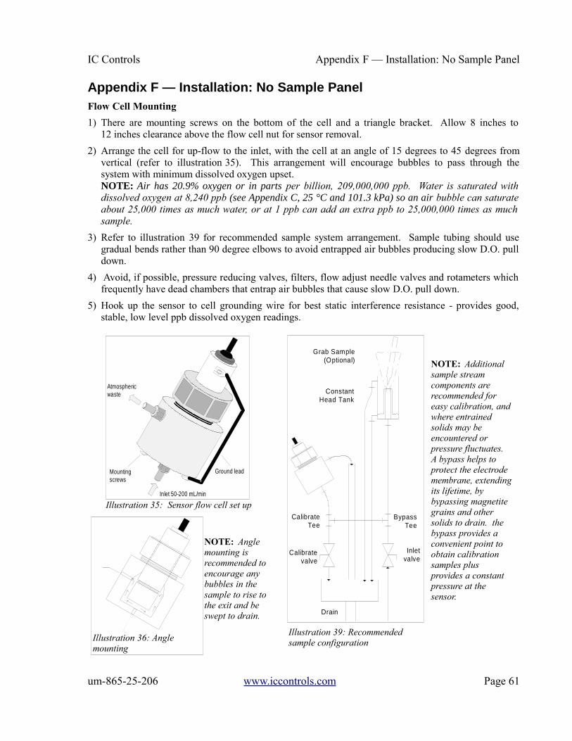
IC Controls Appendix F — Installation: No Sample Panel
Appendix F — Installation: No Sample PanelFlow Cell Mounting
1) There are mounting screws on the bottom of the cell and a triangle bracket. Allow 8 inches to12 inches clearance above the flow cell nut for sensor removal.
2) Arrange the cell for up-flow to the inlet, with the cell at an angle of 15 degrees to 45 degrees fromvertical (refer to illustration 35). This arrangement will encourage bubbles to pass through thesystem with minimum dissolved oxygen upset.NOTE: Air has 20.9% oxygen or in parts per billion, 209,000,000 ppb. Water is saturated withdissolved oxygen at 8,240 ppb (see Appendix C, 25 °C and 101.3 kPa) so an air bubble can saturateabout 25,000 times as much water, or at 1 ppb can add an extra ppb to 25,000,000 times as muchsample.
3) Refer to illustration 39 for recommended sample system arrangement. Sample tubing should usegradual bends rather than 90 degree elbows to avoid entrapped air bubbles producing slow D.O. pulldown.
4) Avoid, if possible, pressure reducing valves, filters, flow adjust needle valves and rotameters whichfrequently have dead chambers that entrap air bubbles that cause slow D.O. pull down.
5) Hook up the sensor to cell grounding wire for best static interference resistance - provides good,stable, low level ppb dissolved oxygen readings.
um-865-25-206 www.iccontrols.com Page 61
Illustration 35: Sensor flow cell set up
NOTE: Additional sample stream components are recommended for easy calibration, andwhere entrained solids may be encountered or pressure fluctuates. A bypass helps to protect the electrode membrane, extendingits lifetime, by bypassing magnetite grains and other solids to drain. the bypass provides a convenient point to obtain calibration samples plus provides a constant pressure at the sensor.
NOTE: Angle mounting is recommended to encourage any bubbles in the sample to rise tothe exit and be swept to drain.
Illustration 39: Recommended sample configuration
Ground lead
Atmosphericwaste
Mountingscrews
Inlet 50-200 mL/min
Calibrate valve
CalibrateTee
Inletvalve
Drain
BypassTee
Constant Head Tank
Grab Sample (Optional)
Illustration 36: Angle mounting
InletDrain

Appendix G — Serial Communications IC Controls
Appendix G — Serial Communications
OverviewThe 865 analyzer is equipped with an RS232 port whichcan be used to establish digital communications with acomputer.
• Timed ASCII output of analyzer inputs to thecomputer. The analyzer can send ppb D.O.,temperature, pressure and auto-range number.This functionality is accessed using the internaldata log menu.
• The IC Net™ Access Program running onMicrosoft Windows. The IC Net™ program canbe used to operate the analyzer in a network ofanalyzers using RS485 communications, displayand log each analyzer’s inputs graphically,retrieve internal data logs, and view eventinformation. The information accessible in the865 analyzer is described in this appendix. Thelicenses for the IC Net program is a separatepurchase.
Wiring and ConfigurationTo connect the 865 analyzer to a computer serial port,consult illustration 37 for the wiring diagram. To enableserial transmission by the analyzer, set the serial ON/OFFswitch to ON (default is ON). Configure the analyzer for thedesired baud rate. Select [SEr] [ baud] from the menu.Baud rates from 1200 baud to 38400 baud can be selected,the default is 9600 baud; see illustration 38. After selectingthe baud rate at the analyzer, ensure that the baud rateselected in the computer's communication program isidentical. If the baud rates do not match, the analyzer and thecomputer will not be able to communicate.
The 865 analyzer serial communications uses 8 data bits, noparity, 1 stop bit.
When using RS232 communications it is recommended that you leave the node number at its defaultvalue of 1. On an RS485 network each unit needs a unique node number.
When it is necessary to connect to a computer without an available RS232 port, an RS232 to USBadapter can be used. IC Controls provides such an adapter as either by itself or as a kit which includesup to 2 hours of technical support. Adapters are also available to convert RS232 to RS485. Refer toAppendix E – Parts List for ordering information.
Page 62 www.iccontrols.com um-865-25-206
Illustration 37: Serial communication wiring
Illustration 38: Serial communication menu

IC Controls Appendix G — Serial Communications
ASCII OutputData transmitted by the analyzer is in simple ASCII format. The 865 continuous output consists ofthree data fields separated by commas. Each line of data is terminated by a linefeed/newline. Comma-separated values are designed to make it easy to import the data into other programs for analysis, forexample into a spreadsheet.
The RS232 port can be used as a data port to send ppb D.O., temperature, pressure and auto-rangenumber (default frequency is 60 seconds).
The ASCII output function is activated and controlled from the Internal Data Log menu.
• Select the internal data log menu.
• Set the frequency of update in seconds [iLOG] [ FrEQ]
• Select [iLOG] [ ASCI ] [ on ].
A terminal program is needed on the computer to display and capture the ASCII data. Versions ofHyperTerminal were included with Windows up to Windows XP. The company that developed theprogram is still independently maintaining and offering this program for sale. Visit the web pagehttp://www.hilgraeve.com/hyperterminal which also contains a link to a trial version of “HyperTerminalPrivate Edition”. Alternatively the free and open-source PuTTY program can be downloaded.
um-865-25-206 www.iccontrols.com Page 63
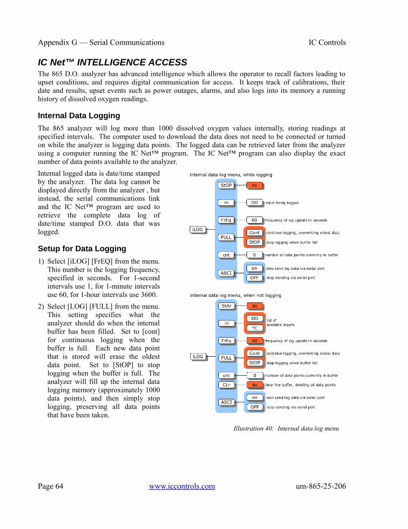
Appendix G — Serial Communications IC Controls
IC Net™ INTELLIGENCE ACCESSThe 865 D.O. analyzer has advanced intelligence which allows the operator to recall factors leading toupset conditions, and requires digital communication for access. It keeps track of calibrations, theirdate and results, upset events such as power outages, alarms, and also logs into its memory a runninghistory of dissolved oxygen readings.
Internal Data Logging
The 865 analyzer will log more than 1000 dissolved oxygen values internally, storing readings atspecified intervals. The computer used to download the data does not need to be connected or turnedon while the analyzer is logging data points. The logged data can be retrieved later from the analyzerusing a computer running the IC Net™ program. The IC Net™ program can also display the exactnumber of data points available to the analyzer.
Internal logged data is date/time stampedby the analyzer. The data log cannot bedisplayed directly from the analyzer , butinstead, the serial communications linkand the IC Net™ program are used toretrieve the complete data log ofdate/time stamped D.O. data that waslogged.
Setup for Data Logging
1) Select [iLOG] [FrEQ] from the menu.This number is the logging frequency,specified in seconds. For 1-secondintervals use 1, for 1-minute intervalsuse 60, for 1-hour intervals use 3600.
2) Select [LOG] [FULL] from the menu.This setting specifies what theanalyzer should do when the internalbuffer has been filled. Set to [cont]for continuous logging when thebuffer is full. Each new data pointthat is stored will erase the oldestdata point. Set to [StOP] to stoplogging when the buffer is full. Theanalyzer will fill up the internal datalogging memory (approximately 1000data points), and then simply stoplogging, preserving all data pointsthat have been taken.
Page 64 www.iccontrols.com um-865-25-206
Illustration 40: Internal data log menu

IC Controls Appendix G — Serial Communications
Retrieving the Internal Data Log
The IC Net™ program running on a computer is used to retrieve the internal data log from the analyzer using the RS232 or RS485 serial communications link.
Displaying Logging Status
From the menu select [LOG] [cnt]. This count number shows the number of data points that have beenlogged. While the analyzer is logging, you will be able to see this number incrementing. The data pointcount will be 0 after the data log has been cleared from memory. Also, the [cnt] frame must show 0before a new data log can be started. The [StAr] frame won’t be in the menu while the analyzer isactively logging data.
Ending a Data Log
To end a data log, i.e., to stop logging more points, select [StOP] from the internal logging menu. PressEnter when the analyzer displays the blinking [do]. The analyzer will briefly display [donE] to indicatethat it has stopped the logging operation.
Data logging will stop automatically if the [FULL] setting is set to [StOP] and the entire logging bufferhas been filled.
Clearing the Data Log from Memory
The data log can be cleared (erased) from the analyzer memory. The menu will not allow you to start anew log until the existing log has been explicitly erased. This is a safety feature to ensure that youdon’t accidentally wipe out an existing log when starting the next log.
To erase the data log from memory:
1) Select [LOG] [CLr] from the menu.
2) With the display flashing [do], press Enter. Note: there is no way to recover a data log oncememory is cleared. Be very sure that you do want to clear the log from memory before pressingEnter.
Calibration & Event History
The analyzer stores important information automatically, tagged with a date/time stamp. The analyzerstores the last 12 calibration records for each input, which is sufficient for a year’s worth of calibrationhistory when monthly calibrations are performed.
Events such as power down, power up, and alarms are recorded in a separate log which tracks the last20 events, time/date stamped. When combined with the internal data logging capability, this allows theoperator to recall factors leading to alarm conditions.
Retrieving Calibrations and Events
At any time, the date/time-stamped events can be retrieved from the analyzer using a computer runningthe IC Net™ program. The display limitations of the analyzer leave no way to view event records usingonly the analyzer. There is no menu for events, and logging is done without any user intervention.
um-865-25-206 www.iccontrols.com Page 65

Appendix G — Serial Communications IC Controls
Event Records
Sample output of event records:
1, Thu Dec 18 14:50:47 1997, ANALYZER OFF
2, Thu Dec 18 17:47:30 1997, ANALYZER ON
3, Thu Dec 18 17:47:30 1997, E1.5
4, Thu Dec 18 17:47:31 1997, E2.2
5, Thu Dec 20 10:11:21 1997, CA7.6
The first number is sequential. The next part of each line is the date/time stamp. The final part is theevent record. Different time/date formats are available.
Calibration Records
Each time a calibration for D.O., temperature, or pressure is changed, the change is recorded in adate/time stamped log. The log is written both when a normal calibration is performed and when acalibration parameter such as offset or efficiency is manually adjusted. Any change in any factoraffecting the calibration is recorded.
Another feature is when the calibration is committed to the internal log. The internal log is not writtenuntil the analyzer has not been used for 15 minutes, then a single record is written the currentcalibration. If for example, two consecutive calibrations are done and then a number of manual changesto % efficiency, these changes only create a single log entry rather than filling 6 of the 12 availablecalibration event tag spaces.
For the ppb D.O. input the following factors are logged:
• % efficiency
• ppb D.O. at time of calibration
• temperature at time of calibration
• pressure at time of calibration
• manual or automatic temperature compensation
• manual or automatic pressure compensation
For temperature the following factor is logged:
• offset
For pressure the following factor is logged:
• offset
Page 66 www.iccontrols.com um-865-25-206

IC Controls DRAWINGS
DRAWINGS
D5940111: Wiring Diagram
um-865-25-206 www.iccontrols.com Page 67

DRAWINGS IC Controls
D5970171: Analyzer Dimensions
Page 68 www.iccontrols.com um-865-25-206

IC Controls DRAWINGS
D4060084: Sample Conditioning Panel Dimensions
um-865-25-206 www.iccontrols.com Page 69

INDUSTRIAL PRODUCTS WARRANTY IC Controls
INDUSTRIAL PRODUCTS WARRANTYIndustrial instruments are warranted to be free from defects in material and workmanship for a period oftwelve (12) months from the date of installation or eighteen (18) months from the date of shipment fromIC CONTROLS whichever is earlier, when used under normal operating conditions and in accordancewith the operating limitations and maintenance procedures in the instruction manual, and when nothaving been subjected to accident, alteration, misuse, or abuse. This warranty is also conditioned uponcalibration and consumable items (electrodes and all solutions) being stored at temperatures between 5°C and 45 °C (40 °F and 110 °F) in a non-corrosive atmosphere. IC CONTROLS consumables orapproved reagents must be used or performance warranty is void. Accessories not manufactured byIC CONTROLS are subject to the manufacturer’s warranty terms and conditions.
Limitations and exclusions:
Industrial electrodes, and replacement parts, are warranted to be free from defects in material andworkmanship for a period of three (3) months from the date of installation or eighteen (18) months fromthe date of shipment when used under normal operating conditions and in accordance with the operatinglimitations and maintenance procedures given in the instruction manual and when not having beensubjected to accident, alteration, misuse, abuse, freezing, scale coating, or poisoning ions.
Chemical solutions, standards or buffers carry an “out-of-box” warranty. Should they be unusable whenfirst “out-of-box”, contact IC CONTROLS immediately for replacement. To be considered for warranty,the product shall have an RA (Return Authorization) number issued by IC CONTROLS servicedepartment for identification and shall be shipped prepaid to IC CONTROLS at the above address.
In the event of failure within the warranty period, IC CONTROLS, or its authorized dealer will, atIC CONTROLS option, repair or replace the product non-conforming to the above warranty, or willrefund the purchase price of the unit.
The warranty described above is exclusive and in lieu of all other warranties whether statutory,express or implied including, but not limited to, any implied warranty of merchantability orfitness for a particular purpose and all warranties arising from the course of dealing or usage oftrade. The buyer’s sole and exclusive remedy is for repair, or replacement of the non-conformingproduct or part thereof, or refund of the purchase price, but in no event shall IC CONTROLS (itscontractors and suppliers of any tier) be liable to the buyer or any person for any special,indirect, incidental or consequential damages whether the claims are based in contract, in tort(including negligence) or otherwise with respect to or arising out of the product furnishedhereunder.
Representations and warranties made by any person, including its authorized dealers, distributors, representatives, and employees of IC CONTROLS, which are inconsistent or in addition to the terms of this warranty shall not be binding upon IC CONTROLS unless in writing and signed by one of its officers.
Page 70 www.iccontrols.com um-865-25-206
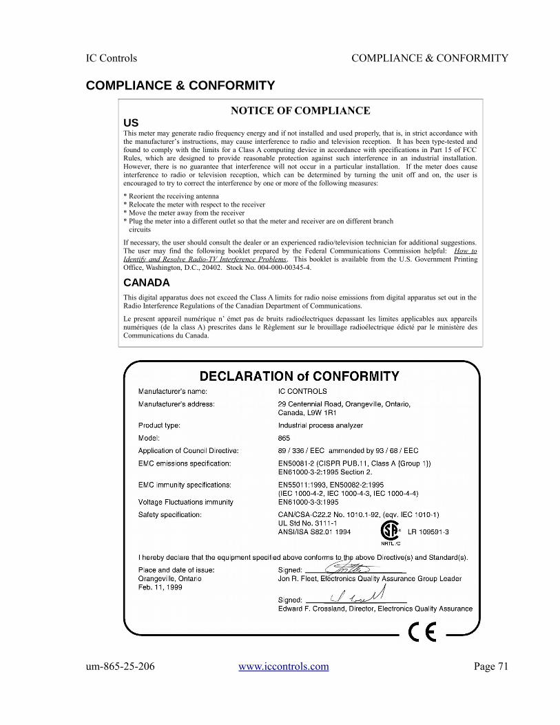
IC Controls COMPLIANCE & CONFORMITY
COMPLIANCE & CONFORMITY
um-865-25-206 www.iccontrols.com Page 71
NOTICE OF COMPLIANCEUSThis meter may generate radio frequency energy and if not installed and used properly, that is, in strict accordance withthe manufacturer’s instructions, may cause interference to radio and television reception. It has been type-tested andfound to comply with the limits for a Class A computing device in accordance with specifications in Part 15 of FCCRules, which are designed to provide reasonable protection against such interference in an industrial installation.However, there is no guarantee that interference will not occur in a particular installation. If the meter does causeinterference to radio or television reception, which can be determined by turning the unit off and on, the user isencouraged to try to correct the interference by one or more of the following measures:
* Reorient the receiving antenna* Relocate the meter with respect to the receiver* Move the meter away from the receiver* Plug the meter into a different outlet so that the meter and receiver are on different branch circuits
If necessary, the user should consult the dealer or an experienced radio/television technician for additional suggestions.The user may find the following booklet prepared by the Federal Communications Commission helpful: How toIdentify and Resolve Radio-TV Interference Problems. This booklet is available from the U.S. Government PrintingOffice, Washington, D.C., 20402. Stock No. 004-000-00345-4.
CANADAThis digital apparatus does not exceed the Class A limits for radio noise emissions from digital apparatus set out in theRadio Interference Regulations of the Canadian Department of Communications.
Le present appareil numérique n’ émet pas de bruits radioélectriques depassant les limites applicables aux appareilsnumériques (de la class A) prescrites dans le Règlement sur le brouillage radioélectrique édicté par le ministère desCommunications du Canada.
INDEX IC Controls
INDEXAccess levels 53Alarms 39
default settings 59deviation 39, 41differential 39, 41fault 39, 41function 39high 40indication of 39low 40on/off control 41relay contacts 42sensitivity of 40set-point 39units 40use of contacts 39wiring 39
Automatic range switching 36Automatic temperature compensation 30Calibration
D.O. input circuit 47electronic 49errors 29in-line 27off-line 28temperature input circuit 47
Caution messages 32, 34Configuration
defaults 59input on/off switch 24re-initializing 42units 42
Current output 35p.calibration 48default settings 59reversing 36settings 36simulating 36span 35testing relay outputs 49
D.O.auto-range 31calibration 27detection circuit 47error messages 33
in-line grab sample check 28in-line zero check 28manual range 31measurement 12off-line zero check 29output signals 35pressure compensation 57temperature compensation 57troubleshooting 46units 56
Default settings 59Diagnostics
memory test 21startup procedure 21
Display prompts 50p.Edit Mode
change settings 25example 25key functions 25numeric values 25
Electrodecleaning 45maintenance 44troubleshooting 46
Error messages 32acknowledging 32alarm 34clearing 32D.O. 33pressure 34temperature 34- sign 32+ sign 32
Fault alarm 41Galvanic cell 12Home base 24Hysteresis 40, 52Imperial units 42Input
on/off configuration 59Installation 42Keypad
arrow keys 24CANCEL key 25DOWN key 25
Page 72 www.iccontrols.com um-865-25-206
IC Controls INDEX
ENTER key 25SELECT key 25UP key 25
LED 32, 52Manual temperature compensation 30Menu
edit settings 25home base 24
Menu Layout 3p.Metric units 42Normally closed 42, 52Normally open 42, 52Output channels 35Output Hold 29Password 53pp.Pressure
automatic compensation 30error messages 34manual compensation 31units 30, 42, 56
Pressure compensation 59Process control 41Range switching
output signals 36Re-initializing settings 43Real-time clock 43Relays 49SAMPLE key 24Sample requirements 13Security
access levels 53access-level 53
disabling 54enabling 53password 43, 54p.password 1 53password 2 53time-out 24
Sensorassembly 17insertion 19removal 19wiring 17
Simulated current output 36Specifications 6pp.Start-up
diagnostics 21procedure 21
Temperaturecurrent output 35error messages 34input calibration 47units 42, 56
Temperature compensation 30, 52, 59Timer
15 minute time-out 24security time-out 24
Troubleshooting 46Units
conversion 56D.O. 56metric or imperial 42pressure 30, 42, 56temperature 42, 56
um-865-25-206 www.iccontrols.com Page 73