user manual package contents specifications · surrounding soil. use a ground pick or additional...
TRANSCRIPT

USER MANUAL CL43 Compact Locator
CL43-PA and CL43-PB
Introduction
CL43 Compact Locator is an easy-to-use wire, cable and sonde locator. CL43 is compatible with all Vesala brand 10kHz and 33kHz transmitters and sondes, as well as Vesala's 512Hz sondes for metal ducts. It also supports 33kHz frequency used by other vendors.
CL43 can be used to trace and pinpoint sondes and underground cables from several metres depth. Indoors CL43 can be used e.g. to locate floor heating cables and wires inside walls or at wire terminals.
Package Contents
Compact Locator CL43-PA:
CL43 Receiver
SA43 Rod probe: 10kHz and 33kHz, tracing distance 30cm...10m
KLCL43 Carrying case
LR03 (AAA) battery, 3 pcs
KOCL43 User manual
Compact Locator CL43-PB:
CL43 Receiver
SA05 Rod probe: 512Hz, tracing distance 30cm...10m
KLCL43 Carrying case
LR03 (AAA) battery, 3 pcs
KOCL43 User manual
Extra Accessories
LA43 Close range probe:
10kHz and 33kHz, tracing distance 0cm...30cm
KA43 Capacitive probe for wire identification, tracing distance 0cm...15cm.
Other accessories include sondes for duct locating and CTT33 transmitter for cable tracing work.
Warnings
Do not use CL43 probes so that they touch live targets. It is not possible to get an electric shock via CL43 receiver probes at less than 600V environment.
Never touch live targets with CL43 body.
Electrical work must be carried out in accordance with electrical safety regulations.
Specifications
Receiving Frequencies 512Hz 10kHz 33kHz (32,768kHz)
Adjustments (2 buttons) Power on/off 7-step gain adjustment Receiving frequency setting
Connections Male XLR for probes
LED-Indicators Green power-LED Red 12-level LED arc display
for receiving signal strength, firmware version and indicating receiving frequency setting
Audio Indicators Internal speaker for trace
signal and indication tones
Batteries 3 pcs 1,5V IEC LR03 (AAA)
alkaline batteries (or corresponding NiZn cells)
Low battery warning at approx. 3.7V
Power Consumption 20...50mA
Enclosure Material and Dimensions Stainless steel and aluminium 180 x Ø40 mm, weight
approx. 230g (including batteries, no probes)
Enclosure Protection Rating IEC 60529 IP44
Operating Conditions -40...+60ºC (dry or damp
conditions)
Storage Conditions -40...+60ºC (dry conditions)
Maintenance, Storage, Warranty
CL43 receiver and probes do not have any parts that require maintenance by the user, excluding changing of batteries. When cleaning a soiled or wet device, clean and dry the device before removing probes or opening battery compartment to avoid dirt or water getting into the battery compartment or connectors. Do not use corrosive solvents for cleaning. If water gets into the CL43 battery compartment, allow it to dry at room temperature. We recommend that the units are stored in dry conditions at room temperature.
H. Vesala Oy is not liable for any financial losses or damages, or for any damage incurred by people, the environment, and telecommunication traffic or similar as a result of the use of or the failure to use the CL43 device or accessories
CL43 has one-year warranty for factory defects. The warranty shall not cover batteries or faults resulting from normal wear and tear or misuse. Users are advised to contact the manufacturer in case of faults or queries relating to the use of the devices. The product has been designed and manufactured in Finland. VESALA® is a registered trademark of H. Vesala Oy.
Contact Information Manufacturing, sales and maintenance:
H. Vesala Oy
Peräsimentie 1, FI-03100 Nummela, FINLAND
Tel. +358 44 200 2005
[email protected] www.vesala.fi
We reserve the right to make changes.
© H.VESALA Oy 1917
Do not discard this product with household or general waste after its end-of-life. Return it for recycling according to EU Waste Electrical and Electronic Equipment directive (WEEE). For more information contact your local distributor or www.vesala.fi.

124 3
CL43 parts
Speaker: Indicates received signal strength; the higher pitch and volume, the stronger the signal.
Arc of 12 Red LEDs: In normal operation arc displays received signal strength with 24 levels. The 512/10k/33k LEDs display the active operating frequency when the frequency is changed or when a probe is connected to the CL43 device while powered on.
Power LED: Green LED indicates power on. LED blinks if battery is weak.
Probe: Choose probe according to the tracing task. CL43 always requires a probe to operate. To attach a probe, push the probe connector (1) in to CL43 socket (2) aligned as in the image until the locking clicks. To remove a probe: Press the release button (3) under the rubber to release the locking and pull the probe out.
Batteries: Batteries are located under the user interface cap. CL43 receiver uses 3 pcs AAA (IEC LR03) alkaline batteries. Compatible NiZn batteries can be used but they must be recharged in a separate charger.
Changing Batteries: Turn the user interface cap (1) off and pull the battery holder (2) out from the tube. Replace old cells with new ones. Observe battery polarity: (-) poles must be placed against the spring contacts. Insert the battery holder back into CL43 tube according to the arrow symbol (3). Turn the user interface cap back on the tube (4).
3
2
1
Probe Release Button: Press here to remove the probe.
Power On / Off: (+) long press
(+) extended press during start-up: make the LED arc show firmware version.
(+) releasing press during start-up: make the LED arc briefly display battery status and the active operating frequency with one of the three rightmost LEDs.
Increase Sensitivity: (+) short press
Gain setting up or down has 5 or 7 steps available depending on connected probe. A beep sound indicates change of gain, no beep means that maximum or minimum has been reached.
Decrease Sensitivity: (-) short press
Change of receiving frequency: (-) long press
1) Press (-) until a beep is heard. Keep it pressed!
2) Press (+) until another beep is heard.
3) One of the 512/10k/33k LEDs briefly indicate chosen frequency.
If necessary repeat 1 to 3 to get the right frequency. Connected probe allows choosing only frequencies supported by the probe. SA05 probe always forces CL43 to 512Hz mode.
Using Probes
Rod probe SA43 or SA05 is typically used by
pointing it towards the target cable or wire. If the cable carries an injected tracing signal current, a very narrow and accurate signal minimum can be seen exactly in the direction of the target. This is called the minimum trace method. Effective tracing distance with rod probes is 30cm to 10m.
Close range probe LA43 is usually set against the surface of the trace area, such as a wall, or moved around a bunch of cables. Also now a narrow signal minimum can often be detected right above the right cable or wire, especially if the distance is short. Effective tracing distance with close range probe is 0cm to 30cm.
Capacitive probe KA43 is typically moved above wires or wire pairs, or above terminals. Effective tracing distance with this probe is 0cm to 15cm.
Locating Duct Sondes
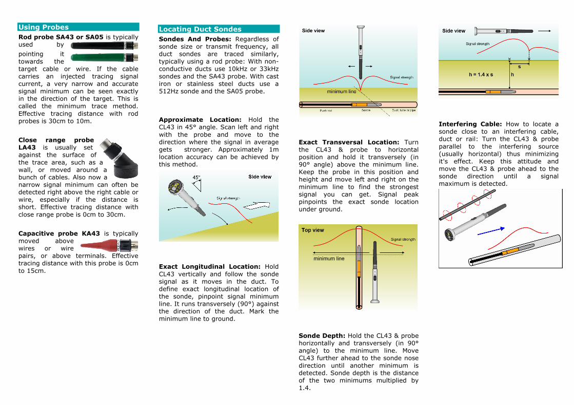
Sondes And Probes: Regardless of sonde size or transmit frequency, all duct sondes are traced similarly, typically using a rod probe: With non-conductive ducts use 10kHz or 33kHz sondes and the SA43 probe. With cast iron or stainless steel ducts use a 512Hz sonde and the SA05 probe.
Approximate Location: Hold the CL43 in 45° angle. Scan left and right with the probe and move to the direction where the signal in average gets stronger. Approximately 1m location accuracy can be achieved by this method.
Exact Longitudinal Location: Hold CL43 vertically and follow the sonde signal as it moves in the duct. To define exact longitudinal location of the sonde, pinpoint signal minimum line. It runs transversely (90°) against the direction of the duct. Mark the minimum line to ground.
Exact Transversal Location: Turn the CL43 & probe to horizontal position and hold it transversely (in 90° angle) above the minimum line. Keep the probe in this position and height and move left and right on the minimum line to find the strongest signal you can get. Signal peak pinpoints the exact sonde location under ground.
Sonde Depth: Hold the CL43 & probe horizontally and transversely (in 90° angle) to the minimum line. Move CL43 further ahead to the sonde nose direction until another minimum is detected. Sonde depth is the distance of the two minimums multiplied by 1.4.
Interfering Cable: How to locate a sonde close to an interfering cable, duct or rail: Turn the CL43 & probe parallel to the interfering source (usually horizontal) thus minimizing it's effect. Keep this attitude and move the CL43 & probe ahead to the sonde direction until a signal maximum is detected.

Using Transmitters
A cable tracer detects the magnetic or electric field which has been induced to a cable or wire using the transmitter. Tracing is often affected by other nearby conductors and ducts.
In order to use a cable tracer transmitter with CL43, select a model with signal frequency of 33 kHz (32,768 kHz). Vesala CTT33 depicted.
Connect the transmitter to the target using supplied feeding cords. Follow electrical safety regulations while connecting. If direct connection is not possible, inductive signal feeding with a clamp-on transformer may be used instead.
Tracing Underground Cables
Transmitter: Always make sure that the tracing signal current return path is distributed widely to the surrounding soil. Use a ground pick or additional wire to accomplish this.
Locate cable route with CL43: Use the SA43 probe to track the signal and cable route. Pinpoint the cable exact location using the minimum method.
Define cable depth with CL43: Tilt the SA43 probe to a 45 degree angle and find a second minimum. Distance between the first minimum A and the second minimum B equals to cable depth.
Tracing Cables at Close Range
Transmitter: If possible, try to ensure that the signal current return path is distributed as wide as possible. To accomplish this use a ground pick, nearby mains sockets PE contact or additional wire connected as far as possible e.g. to a large appliance chassis.
CL43: Use the LA43 probe to track the signal and cable/wire route. Pinpoint the cable exact location using the minimum method.
Hints:
If there are other cables nearby, signal may often be heard on those cables too. Be careful to try which cable gives the strongest signal.
If the tracing signal current's return path is within the same cable, tracing distance will be reduced. Also, as conductors are often twisted inside the cable, the signal strength often appears to go up and down or minimum zigzags from side to side.
Wire Tracing and Identification
Transmitter: Connect both transmitter outputs to the traced wire pair or between a single wire and ground.
CL43: Use KA43 probe and scan as close as possible over the wires or terminal modules to find signal maximum. Strongest signal is above the right wire or pair. A minor minimum may be seen in the middle of the pair. Due to cross talk, signal can be heard elsewhere too but weaker.