user manual - video software and hardware solutions …€¦ · 1.3 stream multiscreen broadcast...
TRANSCRIPT

STREAM MULTISCREEN
User Manual
2010

Stream Multiscreen User Manual
CONTENTS
1 Introduction.................................................................................................................................................5 1.1 Product application ...............................................................................................................................6 1.2 Stream Multiscreen key features...........................................................................................................6 1.3 Stream Multiscreen broadcast control system components ..................................................................7
1.3.1 Main hardware components..........................................................................................................7 1.3.1.1 FS-6 card................................................................................................................................8 1.3.1.2 MS-8 card...............................................................................................................................9 1.3.1.3 Rear panel ..............................................................................................................................9 1.3.1.4 Tally card .............................................................................................................................11
1.3.2 Stream Multiscreen software modules........................................................................................12 1.3.3 Communication network.............................................................................................................13
2 Installing and uninstalling Stream Multiscreen ........................................................................................14 2.1 System requirements...........................................................................................................................14 2.2 Stream Multiscreen installation ..........................................................................................................14 2.3 Stream MultiScreen removal ..............................................................................................................20
3 Working with Stream Multiscreen............................................................................................................21 3.1 Module of searching and adding Video Server modules to the system..............................................21
3.1.1 Module dialog box description ...................................................................................................21 3.1.2 Adding and removing video server modules .............................................................................22
3.2 Video Server module ..........................................................................................................................23 3.2.1 Module description .....................................................................................................................23 3.2.2 Configuring the video server in the Configuration Manager Module .......................................23
3.2.2.1 View Servers Preferences window in the Configuration Manager Module ........................23 3.2.2.2 Setting the properties of the signal source ...........................................................................25
3.3 Configuration Manager Module main window ..................................................................................32 3.3.1 Structure of the main window.....................................................................................................32 3.3.2 Menu items ................................................................................................................................33
3.3.2.1 File menu .............................................................................................................................33 3.3.2.2 Edit menu .............................................................................................................................34 3.3.2.3 View menu ...........................................................................................................................35 3.3.2.4 Objects menu .......................................................................................................................36 3.3.2.5 Servers menu........................................................................................................................38 3.3.2.6 Preferences menu .................................................................................................................40 3.3.2.7 Window menu......................................................................................................................41 3.3.2.8 Help menu............................................................................................................................43
3.3.3 Toolbars ....................................................................................................................................43 3.3.3.1 Standard toolbar ...................................................................................................................43 3.3.3.2 Controls toolbar ...................................................................................................................43 3.3.3.3 Objects toolbar .....................................................................................................................44 3.3.3.4 Status Bar .............................................................................................................................44 3.3.3.5 Server Bar ............................................................................................................................44 3.3.3.6 Window Tabs .......................................................................................................................44
3.4 Working with Configuration Manager Module ..................................................................................45 3.4.1 Configuration elements...............................................................................................................45
3.4.1.1 Window object .....................................................................................................................46
2

3.4.1.2 Audio PPM object................................................................................................................49 3.4.1.3 Caption/Text object..............................................................................................................50 3.4.1.4 Digital Clock object .............................................................................................................52 3.4.1.5 Analog Clock object ............................................................................................................53
3.4.2 Creating active configuration .....................................................................................................55 3.4.2.1 Workspace configuration .....................................................................................................55 3.4.2.2 Editing the properties of signal sources ...............................................................................56
3.4.3 Saving active configuration .......................................................................................................60 3.4.4 Displaying active configuration .................................................................................................61
3.5 System log viewer module .................................................................................................................64 3.5.1 Purpose of module ......................................................................................................................64 3.5.2 Viewer module main window.....................................................................................................64
4 Stream Multiscreen operation with Kramer matrix ..................................................................................69

Stream Multiscreen User Manual
This Manual is provided for information purposes only. The content of this Manual is subject to
change without prior notification. Stream Multiscreen © hardware and software product and its
documentation are protected by "Stream Labs" Copyright. All rights reserved.
4

Stream Multiscreen User Manual
1 Introduction
“Stream Labs” thanks you for showing interest in Stream Multiscreen and hopes that our
cooperation will be fruitful and continuous.
The purpose of this Manual is to provide information and support for users of Stream Multiscreen
hardware software suite based broadcast monitoring systems.
The Manual presents Stream Multiscreen main operation methods, user interface components and
their operation, video and audio monitoring options and settings.
The Manual is recommended as a reference aid for monitoring system operators and
administrators.
If you have any questions, comments or suggestions regarding Stream Multiscreen operation or
documentation, please contact us by any way convenient for you. We will be happy to assist you.
"Stream Labs"
93 Dmitrovskoe Shosse, bldg. 1, Moscow, 127018, Russian Federation
Phone: +7 (495) 739-82-42
Fax: + 7 (495) 739-82-42
E-mail: [email protected]
WEB: www.streamlabs.ru
5

Stream Multiscreen User Manual
1.1 Product application
Stream MultiScreen provides a platform for setting up a broadcast control system. Stream
MultiScreen suite performs simultaneous output of video, audio and additional information of the
received channels on one or several screens, which allows to carry out direct visual on air monitoring.
Stream MultiScreen allows to create various configurations of the system informational elements on the
screen, which helps to effectively address multiple complex challenges of broadcast control and make the
work of the administrator convenient to the maximum. Stream MultiScreen system of alarm messages
allows to detect the emergence of such common broadcast output issues as loss of video and audio signal
etc., and promptly respond to them making your broadcast more reliable and of higher quality.
1.2 Stream Multiscreen key features
Stream Multiscreen system has the following key features:
- Simultaneous control and playback of video and audio signal sources (up to 24 sources in analog
composite version, up to 16 sources in SD-SDI version and up to 32 MPEG TS real time streams on one
or several screens when using several Stream Multiscreen cards;
- Random window configuration (scaling, partial overlapping of video windows), adding audio
indicators, displaying analog and digital clocks and text boxes;
- Support for display of signals on multiple monitors. Support for vertical monitor position;
- High image quality. Supporting resolutions up to WUXGA (1920x1200 pixels);
- Managing signal parameters and error detection, including video and audio loss, silence in audio
channels, frozen video, black frame, and block structure in the frame.
- Visual (blinking frame around the appropriate box) and sonic (playing a sound file with set duration)
warning indications upon discovery of the above errors;
- Customization of response to alarm events for each signal source, including marginal conditions for
error identification and generation of weekly schedule of alarm messages;
6

Stream Multiscreen User Manual - Tracking the alarm events trigger in real time and maintaining a response history (log);
- System backup power supply,
- Quick change of video windows layout configurations by pressing “hot buttons”, with the use of an
external control panel and according to the set schedule;
- User-friendly software interface for creating presets that control the output to LCD monitors, drag &
drop support;
- Connecting Stream MultiScreen TS to LAN allows to combine several devices into a single network,
which can be fully controlled from any workstation in the network.
1.3 Stream Multiscreen broadcast control system components
1.3.1 Main hardware components
The main hardware components of Stream Multiscreen complex are:
Stream Multiscreen cards, expansion cards for video and audio inputs, Tally cards.
1. Stream Multiscreen cards.
2. PC-based (IBM PC-based) Operator or Administrator workstations (remote workstations).
3. PC-based (IBM PC based) video servers with specialized equipment (and video capture cards)
installed, which perform additional functions of the Operator and System Administrator
workstation.
7

Stream Multiscreen User Manual
1.3.1.1 FS-6 card
FS-6 card is designed to work with analog video signals.
Card features:
PCI-Express 1x,
4 CVBS video inputs,
4 RCA jack line audio inputs (fem.),
Tally card connector,
connectors for video and audio sources connection to the rear panel.
Fig. 1.3.1 FS-6 card
8

Stream Multiscreen User Manual
1.3.1.2 MS-8 card
MS-8 card is designed to work with digital and analog video signals.
Card features:
PCI-X 64bit/66 MHz interface,
8 CVBS/SDI video inputs + CVBS/VBS reference signal,
8 RCA jack line audio inputs (fem.),
Tally card connector,
connectors for video and audio sources connection to the rear panel.
Fig. 1.3.2 MS-8 card
1.3.1.3 Rear panel
Rear panel has a standard signal sources input (BNC-in-video, RCA-in-audio) interface. The
cards are designed for installation on the back panel of Stream Multiscreen server. Figure
1.3.3 shows a typical configuration of Stream Multiscreen server.
9

Stream Multiscreen User Manual
Fig. 1.3.3 Rear panel of 16 channel Stream Multiscreen server
10

Stream Multiscreen User Manual
Fig. 1.3.4 Rear panel of 24 channel Stream Multiscreen server
Figures 1.3.3 and 1.3.4 present the rear panels of sixteen and twenty-four channel servers. The video
connectors’ layout and numbering is shown at the top of the image, the audio – in the middle. The bottom
of the figure displays the general view of the server back panel.
11

Stream Multiscreen User Manual
1.3.1.4 Tally card
Tally card is designed to manage Stream Multiscreen program operation from a console, it is
installed on the back panel of Stream Multiscreen server.
Fig. 1.3.6 Tally card for FS-6
Fig. 1.3.5 Tally connector
assignment Fig. 1.3.7 Tally card for MS-8
12

Stream Multiscreen User Manual
The system response to Tally event (contact closure) can be configured in the video server
settings window, in Configuration Manager Module (see Section 3.2.2).
1.3.2 Stream Multiscreen software modules
Stream Multiscreen complex is represented by the following system modules:
1) Module of searching and adding Video Server modules to the system - system module,
which performs a search of active Video Server components in the network. This module is
built into the Configuration Manager and System log viewer components and it establishes
a connection between these components and the active Video Server modules in the network.
2) Video Server - system module which interacts directly with the system hardware. This
module is installed on machines with Stream Multiscreen cards, where the information on
controlled video sources will be displayed. Video Server module collects information about
Multiscreen cards and monitors connected to the server. This data is passed to the
Configuration Manager module to create the configuration of available video sources. In
addition, Video Server module displays the finished monitor configuration after it is received
from the Configuration Manager module.
3) Configuration Manager - system module designed for managing video servers. This module
allows you to create different configurations of available video signal sources and transmit
them to Video Server module for display. In addition, Configuration Manager allows you
to customize the response of the Video Server components to alarm events (events recorded
in the system, associated with the distortion or loss of signal, as well as GPI control signals).
4) System log viewer - system module designed to collect and display system log information
of Video Server modules. When you start the Viewer, it automatically runs the search for all
active Video Server components in the network. The server data is transferred to the Viewer,
after which the module starts to display the system log information of all available servers in
real time.
13

Stream Multiscreen User Manual
1.3.3 Communication environment
Communication resources of Stream Multiscreen hardware-software complex allow to create the
distributed monitoring systems of television video and audio signals sources. Remote system components
automatically interact with one another, forming a uniform monitoring network.
Data exchange and communication between the elements of the system is performed via local
computer networks (LAN), Internet channels (WAN), telephone lines (Dial-Up) by using TCP / IP
transport protocol.
14

Stream Multiscreen User Manual
2 Installing and uninstalling Stream Multiscreen
2.1 System requirements
All Stream Multiscreen software modules are supported on the following Operating Systems: Windows 2000 (SP3 and higher), Windows 2003 Server, Windows XP.
2.2 Stream Multiscreen installation
In order to install and uninstall all the system components it is necessary to run the program
setup. If InstallShield Wizard detects an existing version of the system on the computer, the following
window will appear (Figure 2.1):
Fig.2.1 Program reinstall / uninstall options window
In this window, InstallShield Wizard will let you choose the following options:
15

Stream Multiscreen User Manual
Add/Remove program components (Modify)
Update all files in the installed program (Repair)
Remove the program completely (Delete)
It is recommended to remove the existing version of the program before installing a new version.
If you are installing Stream Multiscreen for the first time, or if the previous version has already
been removed from your PC, you will see the InstallShield Wizard welcome window after you run the
setup file (Figure 2.2).
Fig. 2.2 InstallShield Wizard welcome window
After clicking Next, you will be prompted to choose a folder for the program installation (Figure
2.3). If you click Next again, the program will be installed in the default directory (C: \ Program Files \
16

Stream Multiscreen User Manual Stream Labs \ Stream MultiScreen). To specify a different destination folder, use Browse. If your
specified folder does not exist yet, it will be automatically created during installation.
Fig. 2.3 Selecting the program installation folder
After selecting the installation folder and clicking Next, you will be prompted to select the
program components you wish to install (Figure 2.4).
17
Stream Multiscreen User Manual
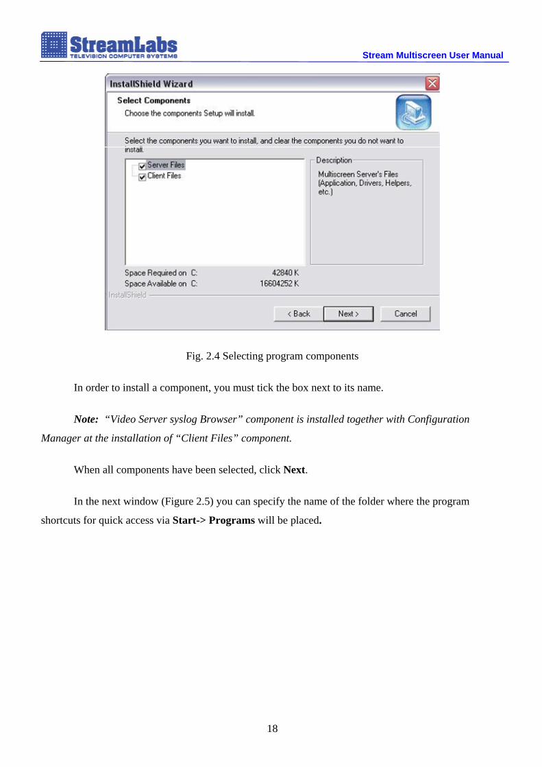
Fig. 2.4 Selecting program components
In order to install a component, you must tick the box next to its name.
Note: “Video Server syslog Browser” component is installed together with Configuration
Manager at the installation of “Client Files” component.
When all components have been selected, click Next.
In the next window (Figure 2.5) you can specify the name of the folder where the program
shortcuts for quick access via Start-> Programs will be placed.
18

Stream Multiscreen User Manual
Fig. 2.5 Selecting the name of the program folder in Start menu-> Programs.
Now click Next and the program installation will begin.
In the process of copying data system warnings may appear (Figure 2.6). In this case, in order to
continue the installation, click “Continue Anyway”.
Fig. 2.6 System warning during installation
After successful completion of the installation InstallShield Wizard will ask you to restart your
computer (Figure 2.7).
19

Stream Multiscreen User Manual
Fig. 2.7 Completion of the installation process
We recommend that you restart the computer immediately after installation. After the reboot the
desktop icons should appear for all installed components of the program. If Multiscreen Server
20

Stream Multiscreen User Manual component is installed, it will load automatically on computer startup and its icon will appear in the
system tray.
The installation is finished and you're now ready to work.
2.3 Stream MultiScreen removal
To uninstall Stream Multiscreen, run the program setup and select Remove (Uninstall) option in
the dialog box (Figure 2.1). After clicking Next the program will be removed.
21

Stream Multiscreen User Manual
3 Working with Stream Multiscreen
3.1 Module of searching and adding Video Server modules to the system
3.1.1 Module dialog box description
Module of searching and adding Video Server modules to the system is a connecting element
which establishes communication between main system components (see section 1.3.2). This module is
called automatically when the Configuration Manager and System log viewer are loaded.
Fig. 3.1 Module of searching and adding Video Server components to the system dialog window
Besides automatic loading, the dialogue window of the module can be called manually:
- In Configuration Manager Module (3.3). – through Servers menu –> Update
Servers/Sources or by pressing ,
- In System log viewer module (3.5) – by pressing Check MSServers button.
22

Stream Multiscreen User Manual
The module dialog box (Figure 3.1) displays all Video Server components found in automatic
mode and available at the moment, as well as those specified earlier in the manual mode.
A record of each Video Server component in the module dialog window is presented in the
following information fields:
Active – indicates that Video Server module is active (used by the system).
Link Name – video server name used in the system (default: MSServer(xxx.xxx.xxx.xxx), where
xxx.xxx.xxx.xxx – is the module IP address). When necessary, you can assign a random name to the
server by selecting this field.
IP Address – IP address of the computer where the video server module is installed. You can edit the
video server IP address by selecting this field*.
*Note: Avoid changing the IP-address of the video server found in the automatic mode, as this could
lead to loss of communication with data servers.
Status – a field which shows the video server availability. Possible values: Accessible - module is
available at the moment, Inaccessible - module is not available.
3.1.2 Adding and removing video server modules
To add a video server module manually, left click in the Active field of the first free line in the
video servers entries. A new video server module account will appear in the table with the default fields
(Link Name - MSServer (0.0.0.0), IP address - 0.0.0.0., Status - Inaccessible). In order to make the
video server accessible, you must specify the IP address of the computer where the video server module
is installed in the IP address field. After specifying the IP address, the program will try to connect to the
video server. If the connection attempt is successful, the Status field will change to Accessible, otherwise
it will stay Inaccessible.
To remove a video server module from the list, left click in the Active field of the appropriate
account and confirm the deletion by clicking Yes in the window.
23

Stream Multiscreen User Manual
3.2 Video Server module
3.2.1 Module description
Executable file: MSServer.exe. Video Server module does not have a user interface. When
loading, a “TV set” icon will appear in the system tray. To shut the module down, right click on the
icon and select Exit (stop video server operation) from the menu.
3.2.2 Configuring the video server in the Configuration Manager Module
3.2.2.1 View Servers Preferences window in the Configuration Manager Module
Despite the lack of a visual interface, the properties of video server module can be configured
through the Configuration Manager Module.
In order to adjust the properties of the video server, run the Configuration Manager Module and
select View Server Preferences in the Servers menu. In the window that appears, you can see a list of
all currently available video servers on the left. If you double click the selected server, all available signal
sources will appear under the server icon (Fig.3.2).
Video Server Settings:
- Playback parameters: Transport Stream files storage path – full path to the directory on your
video server hard disk for output of TS streams from files (used for demonstration purposes).
- Recording parameters: Transport Stream files storage path – full path to the directory for
recording video streams on the video server local hard disk.
- Configure Kramer inputs: Change – change the KRAMER matrix connection configuration
(for more information on the use of Kramer matrix, see Appendix A).
24

Stream Multiscreen User Manual
Depending on the card, the following video sources may be available for configuration:
- MPEG_TS format transport stream (MPEG2 transport stream, ISO/IEC 13818-1
with Mpeg2/H.264 compression codec);
- analog video signal from card input;
- digital / analog video signal from card input.
When you select the signal source icon, the panel with the properties of this source appears on the
right (Fig. 3.2).
25

Stream Multiscreen User Manual
Figure 3.2 View Server Preferences window
26

Stream Multiscreen User Manual
3.2.2.2 Setting the properties of the signal source
Channel name
Figure 3.3 Caption panel
The names of the channels are set in the program by default according to the type of the signal
source. Nevertheless, it is possible to change the name of the channel to any desired value. In order to do
this, in the Caption (Title) panel select the name of the channel manually and enter the name in the
opened field.
Setting the properties of the alarm events
Fig. 3.4 Event Properties window
The program allows to customize the system response when it encounters the following alarm
events:
27

Stream Multiscreen User Manual
Video Loss – disappearance of the video signal source
Fig. 3.5 Video Loss alarm event settings
Frozen Video – still video image from the signal source
Fig. 3.6 Frozen Video alarm event settings
This alarm event has the following settings:
Actuation interval – the time interval over which the system will respond to the alarm event.
Value(T), % – the threshold sensitivity of the similarity of the two frames in comparison
(how similar the images in the frames should be to consider them identical).
28
Stream Multiscreen User Manual
Value(C), % – the threshold sensitivity of the sampling from the actuation interval (the
number of frames from the total actuation interval, which exceeded the Value (T)
parameter). When this parameter is exceeded, the decision on occurrence of alarm event
is made.
Scheduler – schedule compilation wizard, which allows to track the emergence of alarm
events in the time intervals defined by the user.
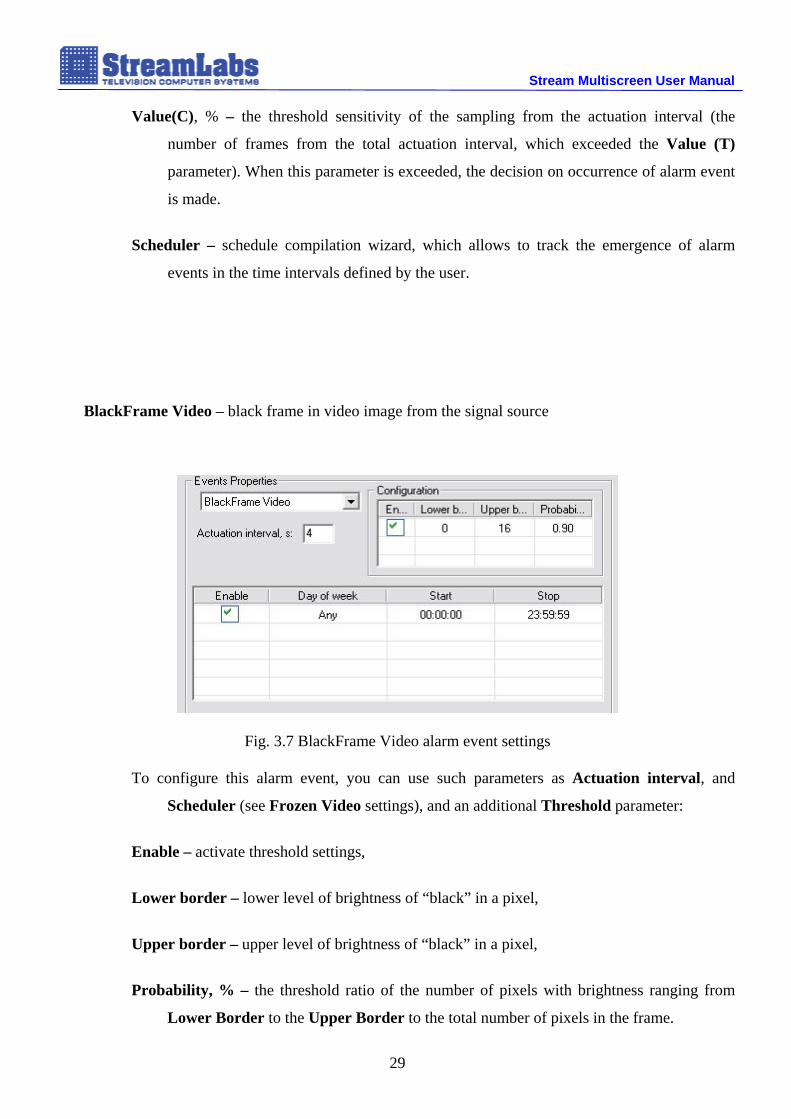
BlackFrame Video – black frame in video image from the signal source
Fig. 3.7 BlackFrame Video alarm event settings
To configure this alarm event, you can use such parameters as Actuation interval, and
Scheduler (see Frozen Video settings), and an additional Threshold parameter:
Enable – activate threshold settings,
Lower border – lower level of brightness of “black” in a pixel,
Upper border – upper level of brightness of “black” in a pixel,
Probability, % – the threshold ratio of the number of pixels with brightness ranging from
Lower Border to the Upper Border to the total number of pixels in the frame.
29
Stream Multiscreen User Manual
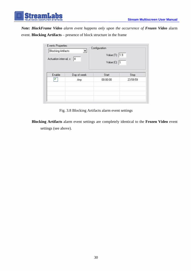
Note: BlackFrame Video alarm event happens only upon the occurrence of Frozen Video alarm
event. Blocking Artifacts – presence of block structure in the frame
Fig. 3.8 Blocking Artifacts alarm event settings
Blocking Artifacts alarm event settings are completely identical to the Frozen Video event
settings (see above).
30

Stream Multiscreen User Manual
GPI (Tally) – Tally actuation signal from the signal source (more about Tally see Section 1.3.1)
Fig. 3.9 GPI (Tally) alarm event settings
Tally alarm event settings feature the familiar option Scheduler (see Frozen Video settings
paragraph).
Audio Loss – loss of sound in the channel
Fig. 3.10 Audio Loss alarm event settings
In addition to standard parameters, such as Actuation interval and Scheduler, there is an
extra Audio loss interval setting. This field specifies the interval, during which the
absence of sound in the channel should be observed.
Audio Silence – audio signal level decline
31

Stream Multiscreen User Manual
Fig. 3.11 Audio Silence alarm event settings
Audio Silence alarm event panel contains the following fields: Actuation interval and
Scheduler (see Frozen Video settings). In addition, there are special fields for defining
the audio level threshold value
History, ms – time during which the decline of audio level below threshold value is observed.
Silence Threshold, % – threshold value of signal level.
TSCC Error – loss of transport stream packages
Fig. 3.11 TSCC Error alarm event settings
This alarm event can be configured with two settings: Actuation interval, and Scheduler.
32

Stream Multiscreen User Manual
Scrambled Stream – notification of an encrypted stream
Fig. 3.13 Scrambled Stream alarm event settings
The Scrambled Stream alarm event panel provides only the Scheduler field (see Frozen Video
settings).
Setting the alarm event response
The system has three types of response to the appearance of an alarm event:
Fig. 3.14 Alarm event response settings
Border – frame around the signal channel display element (video / audio)
Settings:
Border Blinks – allow flashing frame
Border Color – frame color adjustment
Border Width – setting the frame width in pixels
33

Stream Multiscreen User Manual
Audio Signal
Settings:
Audio signal – enable audio
Duration – sound duration
Marker – displaying an alarm event marker in the frame
Settings:
Marker – enable alarm event marker
Apply button
Fig. 3.15 Apply button
Apply button allows you to extend the alarm event settings configuration to all signal sources of
the same type.
34

Stream Multiscreen User Manual
3.3 Configuration Manager Module main window
3.3.1 Structure of the main window Configuration Manager Module presents an environment for creation and management of video
server configurations.
Fig. 3.2 Configuration Manager Module main window
Configuration Manager Module main window consists of the following components:
Menu items: File, Edit, View, Objects, Preferences, Window, Help,
Toolbars: Standard, Controls, Objects, Status Bar, Server Bar, Window Tabs,
Workspace,
Control panels: Objects, Properties, Sources.
In the following section we give a detailed description of the above components.
35

Stream Multiscreen User Manual
3.3.2 Menu items
3.3.2.1 File menu
New [Ctrl + N] – create a new (empty) configuration
Open [Ctrl + O] – open an existing configuration (configuration files have the ._mc extension)
Close – close active configuration
Save [Ctrl + S] – save active configuration
Save As – save active configuration under a different name
Print [Ctrl + P] – print active configuration
Print Preview – preview active configuration before printing
Print Setup – print settings
MRU Files – last opened configuration files (MRU - Most Recently Used)
Exit – close the application with the option to save all changes in all the edited configurations
36

Stream Multiscreen User Manual
3.3.2.2 Edit menu
Undo [Ctrl + Z] – cancel the last editing operation in the active configuration (command depth – one action)
Redo – repeat the last editing operation in the active configuration (if it was cancelled by Undo command)
Cut [Ctrl + X] – remove the selected object from the active configuration and save it to the clipboard
Copy [Ctrl + C] – copy the selected object in the active configuration and save it to the clipboard
Paste [Ctrl + V] – insert an object from the clipboard into the active configuration
Delete [Del] – remove selected objects from active configuration
Select All [Ctrl + A] – select all objects in the active configuration
Properties [Alt + Enter] – show properties (in Properties window) of the selected object in active configuration (object properties are displayed automatically when you right click an object)
37

Stream Multiscreen User Manual
3.3.2.3 View menu
Standard – show / hide the standard toolbar
Controls – show / hide Objects, Properties, Sources, Templates toolbars
Objects – show / hide the object settings toolbar
Status Bar – show / hide the application status bar
Server Bar – show / hide the video server settings toolbar
Zoom – scale the active configuration working canvas
- Zoom In – magnify image
- Zoom Out – reduce image
- Zoom 1:1 – display image in 1:1 scale
- Zoom to Window – display image in the workspace window (scale to the size of the window)
Window Tabs – show / hide the tabs with the open application configurations
38

Stream Multiscreen User Manual
3.3.2.4 Objects menu
Snap to grid – enable / disable the binding of window object to the grid (see Preferences menu)
Z-order – change the "level" of the selected object in active configuration
- Move To Front [Ctrl + Plus] – place the selected object “above” the rest of the objects
- Move To Back [Ctrl + Minus] – place the selected object “below” the rest of the objects
- Move Forward [Plus] – move the selected object one level higher
- Move Back [Minus] – move the selected object one level lower
Align – align the selected objects according to the “reference object” in the active configuration
Note: The reference object is the last selected object.
- Left – position alignment by the left edge
- Top – position alignment by the upper edge
- Right – position alignment by the right edge
- Bottom – position alignment by the lower edge
39

Stream Multiscreen User Manual
Make Same Size - align the sizes of the selected objects according to the “reference object” in the active configuration
- Width – size alignment by width
- Height – size alignment by height
- Both – size alignment by width and height
Space Evenly - align the intervals between the selected objects in the active configuration
- Across – align intervals horizontally
- Down – align intervals vertically
40

Stream Multiscreen User Manual
3.3.2.5 Servers menu
Send configuration to server... – open the dialog for sending an active configuration of one of the
available Video Server modules to a monitor.
Note: It is impossible to send an “empty” configuration, or a configuration in which one or more objects
extend beyond the limits of the workspace.
Update Servers/Sources... – open the dialog of searching and adding Video Server modules to the
system (see Section 6.1).
41

Stream Multiscreen User Manual View Servers Preferences... – open the dialog for adjusting the preferences of the available Video
Server modules.
42

Stream Multiscreen User Manual
This dialog allows you to change the basic settings of the Video Server modules, and some
properties (actuation schedule and response to alarm events, log entries) of the signal sources which
belong to these modules (see Section 3.2.2.1).
43

Stream Multiscreen User Manual
3.3.2.6 Preferences menu
Open the Preferences dialog. Note: this dialog changes the preferences for the Configuration Manager Module only.
Editor – editor settings
Grid – editor window grid parameters:
Enable – show / hide grid
Color – grid color
Marker – type of grid lines (line, dotted line, points)
Size X-axis (pix) – change the interval between neighboring grid lines horizontally (the size is specified in pixels)
Size Y-axis (pix) – change the interval between neighboring grid lines vertically (the size is specified in pixels)
44

Stream Multiscreen User Manual
3.3.2.7 Window menu
New Window - create a new (duplicate) active configuration representation window
Note: A configuration can have one or more representation windows. This property can be used to edit
the configuration in different scales: one window can display the general configuration scheme, the other
- some specific segment.
Cascade - arrange the configuration windows in a “cascade” (overlap)
Tile - arrange the configuration windows one after another vertically
Arrange Icons - arrange icons at the bottom of the window
Next Window - switch to the next configuration presentation window
Previous Window - switch to the previous configuration presentation window
Close All – close all configuration presentation windows
Save All - save changes in all configuration presentation windows
Windows - management the arrangement of windows on the screen. To change the location of windows,
first choose the windows that you wish to change the location for from the list, and secondly, specify
their arrangement on the screen.
A window is selected by clicking on its name. The name of the selected window is highlighted in
blue. To select two or more windows, hold the “Ctrl” button and click the on the names of those windows
45
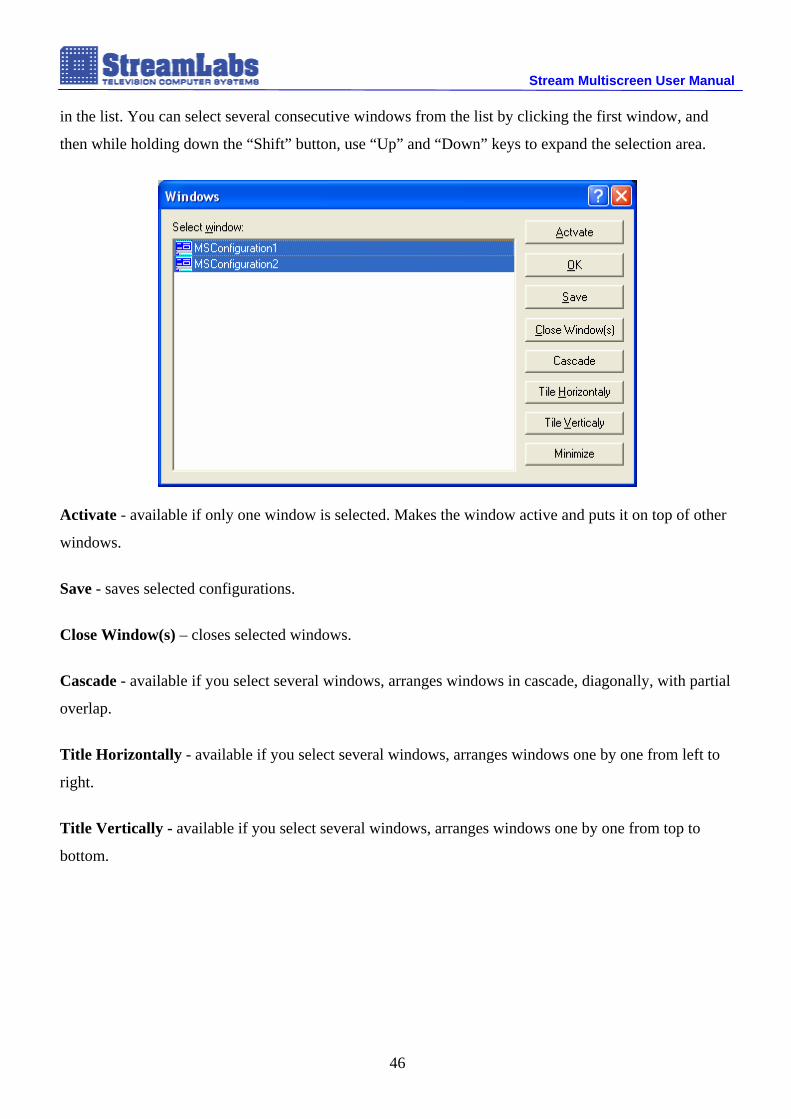
Stream Multiscreen User Manual in the list. You can select several consecutive windows from the list by clicking the first window, and
then while holding down the “Shift” button, use “Up” and “Down” keys to expand the selection area.
Activate - available if only one window is selected. Makes the window active and puts it on top of other
windows.
Save - saves selected configurations.
Close Window(s) – closes selected windows.
Cascade - available if you select several windows, arranges windows in cascade, diagonally, with partial
overlap.
Title Horizontally - available if you select several windows, arranges windows one by one from left to
right.
Title Vertically - available if you select several windows, arranges windows one by one from top to
bottom.
46

Stream Multiscreen User Manual
3.3.2.8 Help menu
About - brings up a window of information about the program
3.3.3 Toolbars
3.3.3.1 Standard toolbar
In addition to the standard working with files options, common to all Windows-based
applications, the panel features View-> Zoom menu functions (see Section 3.3.2.3).
3.3.3.2 Controls toolbar
This panel has four buttons that allow you to show / hide the following elements of the main
window:
1 – Objects workspace panel
2 – Properties workspace panel
3 – Sources workspace panel
4 – Show / hide templates
47

Stream Multiscreen User Manual
3.3.3.3 Objects toolbar
This toolbar contains the components of the Objects menu (see Section 3.3.2.4).
3.3.3.4 Status Bar
Status Bar is located at the bottom of the main window and it contains information about current
operations in the program window. This is an informational panel, it has no buttons or other active fields.
3.3.3.5 Server Bar
This toolbar displays the contents of the Servers menu (see Section 3.3.2.4).
3.3.3.6 Window Tabs
Window Tabs panel displays open configurations, as well as various implementations of the
same configuration in the form of tabs.
48

Stream Multiscreen User Manual
3.4 Working with Configuration Manager Module
3.4.1 Configuration elements
To display video, audio and service information, the system uses the following objects (their
icons are located in Objects window):
Window - video source display
PPM - audio source indication
Text/Caption - source caption and other text fields
Digital Clock – digital clock display
Analog Clock – analog clock display
Object properties:
Border – frame around the object. You can adjust its parameters: Width (thickness) and Color. If
Width equals 0, the border is invisible.
Layout - location of the object (arbitrary) within the configuration resolution. Has Left (indent from the
left edge, in pixels) and Top (offset from the upper edge, in pixels) parameters.
49

Stream Multiscreen User Manual
Size - size of the object (random) within the configuration resolution.
Adding an object to the configuration is performed by dragging its icon from the Objects panel
into the workspace. When you select an object in the workspace, the panel of its properties appears on
the left side of the screen. Let us look at some accessible configuration objects and their properties in
more detail.
3.4.1.1 Window object
When you add the Window object to the configuration editing area, it is displayed as a gray
square:
The size and position of the window change just as the size of the windows in Windows
environment – by stretching from the edge and from the corner and moving to a new position with the
mouse.
After the window has been assigned a signal source, it becomes a blue square in which a
summary of the video source is displayed:
50

Stream Multiscreen User Manual
In addition to assigning the signal source fields manually, the program provides automatic
assignment of a signal source to a window by dragging the signal source icon from the Sources panel
into the object window area.
If the video server which is related to the window signal source stops operation, the window is
displayed as a rectangle with red grid, indicating that you must restart the server, so that configuration
performance can be restored.
Window object properties:
Aspect - indication of window size proportions. Possible options: None – no proportions, 4:3, 5:4, 16:9
– 4:3, 5:4, 16:9 proportions respectively.
51

Stream Multiscreen User Manual
Source - list of available for editing video source properties assigned to the object (see Section 7.3.). If
Window object does not have any source assigned to it, this list will feature only one item – Type with
“None” value.
<Video Loss> picture - choice of Window object display in case of video signal loss. Possible options:
<Video Loss> on Black Screen - «Video Loss» inscription on a black background, or Bars - standard
image with colored rectangles.
52

Stream Multiscreen User Manual
3.4.1.2 Audio PPM object
Audio PPM object is an indicator of audio source operation. When added to the workspace, it is
displayed in the following way:
PPM object properties:
Source - list of available for editing audio source properties assigned to the object. If Audio PPM object
does not have any source assigned to it, this list will feature only one item – Type with “None” value.
Orientation - you can select the type of scale display - vertical or horizontal.
Markers - object band indication setting. Properties available for editing:
Audio PPM object scale is divided into three areas: for analog audio: up to 0 dB (“green” zone),
0 – 2 dB (“orange” zone), 2 - 5 dB (“red” zone); for digital audio: up to -14 dB (“green” zone), -14 –12
dB (“orange” zone), -12 - -9 dB (“red” zone);
53

Stream Multiscreen User Manual - Digits - display the values of each zone in dB (decibels) or not.
- Font - font used to display Digits
- Color - color of the font used to display Digits
Background - choose the object backing type (background design). Possible variations: Transparent -
transparent; Color - monochrome; Texture – use embedded image. If you select Color, you will be able
to choose a color from the palette in the Object item. In Transparent and Texture modes the Object
item is disabled.
Channels - indication of both (stereo), or only the left or only right (mono) audio channels.
Play audio - simultaneous playback of audio through the sound card.
Attached to - group Audio PPM object with Window type object. The object must be selected from the
list. If there are no Window type objects in the current configuration, the list will be empty.
3.4.1.3 Caption/Text object
Text/Caption object serves as a field for creating channel captures and adding text messages in
the configuration. When added to the workspace, it is displayed in the following way:
54

Stream Multiscreen User Manual
Caption/Text object properties:
Caption – object text. Depending on the configuration of the Source Dependent and Attached to:
properties (see below), this item is filled either manually or automatically (when specifying the relation
or assignment to the signal source). In this case, the Caption field automatically receives the name of the
signal source assigned to the Window object. The default field value is “Title”.
Source Dependent – choose automatic / manual object text fill. “Yes” position designates automatic fill,
“No” means manual.
Font – font used to display text.
Color – color of the font used to display text.
Alignment – align text horizontally (Horizontal): “Left” - to the left, “Center” - to the center, “Right” -
by the right edge and vertically (Vertical): “Top” - on the upper edge, “Center” - the center, “Bottom” -
on the bottom edge within the object.
Background – choose the object backing type (see description of Audio PPM object properties).
Attached to – group with Window type object (see description of Audio PPM object properties).
55

Stream Multiscreen User Manual
3.4.1.4 Digital Clock object
Digital Clock object is a system time display panel in the form of a digital clock. When added to
the workspace, Digital Clock object takes the following form.
Digital Clock object properties:
Format – adjust date/time display mode.
- Display Mode – choose date/time display. “Time <Sep> Date” - time < separator> date; “Date <Sep> Time” - date < separator > time; “Time” - time only; “Date” - date only.
- Time Format – choose time display format.
- Date Format – choose date display format.
- <Sep> Char – choose date/time separator symbol ([SPACE]/[ENTER]).
- <Sep> Count – amount of date/time separator symbols.
Font – font used to display digital clock capture.
Color – color of the font used to display digital clock capture.
Alignment – alignment parameter (see description of Audio PPM object properties).
56

Stream Multiscreen User Manual Background – choose the object backing type (see description of Audio PPM object properties).
Time Zone – time zone selection (Time Zone Information), local time which will be displayed in the
object.
Attached to – group with Window type object (see description of Audio PPM object properties).
3.4.1.5 Analog Clock object
Analog Clock object is a system time display panel in the form of an analog clock. When added
to the workspace, Analog Clock object takes the following form.
Analog Clock object properties:
Analog Clock object is added to the configuration by dragging its icon from the Objects window into the
configuration editing area.
Type – choose one of the built-in analog clock samples.
57

Stream Multiscreen User Manual
The system has 3 types of analog clocks in total, however the user can also create a clock with
customized design. To do this, contact Stream Labs technical support (see Introduction).
Time Zone – as in Digital Clock object (see description of Digital Clock object properties above).
Attached to – as in Digital Clock object (see description of Digital Clock object properties above).
58

Stream Multiscreen User Manual
3.4.2 Creating active configuration
3.4.2.1 Workspace configuration
To create a new workspace configuration it is necessary to:
1. Create a new blank document (menu File => New) or switch to a new configuration window
created when opening the module.
2. Update the list of available servers (Menu Servers -> Update Servers / Sources or icon).
3. In the Properties window, in the Destination field select one of the currently available Video
Server modules (Server item).
4. In the same window, choose from one of the server monitors from the list. The size of the
workspace will change to the size of the selected monitor.
Note: if you do not choose a server (None), you can specify an arbitrary size for a "virtual" monitor.
5. In the Properties window, in the Background field select the type of backing (monochrome fill
or a picture from a file). Object item allows you to select a color or an image for a fill.
6. From the Objects window drag (drag-and-drop) the objects used in the configuration (windows,
PPM indicators, text labels, digital or analog clocks, etc.).
Note: For correct use of Window object and Audio PPM object, the controlled source must be specified.
59

Stream Multiscreen User Manual
7. From the Objects window drag all the necessary objects into the configuration editing area.
8. From the Sources window drag (drag-and-drop) (onto Window and Audio PPM objects) the
signal sources from the server, for which for the current configuration is being prepared.
Note: The list of selected server sources opens by double-clicking on the server name. Transport
streams are indicated by icon, and signals coming from video cards inputs are marked .
9. By clicking on Window and Audio PPM objects in the Properties window, you can edit the
properties of the source assigned to the object (see Section 3.3.2.2).
3.4.2.2 Editing the properties of signal sources
Stream Multiscreen allows working with video and audio sources of the following types:
Video sources:
composite CVBS video signal from the card input (FS-6, MS-8),
digital SD-SDI signal from the card input (MS-8)
transport stream MPEG_TS (MPEG2 format, ISO/IEC 13818-1 with Mpeg2/H.264 compression
codec)
Audio sources:
analog audio
SDI Embedded audio
MPEG_TS (MPEG2 format, ISO/IEC 13818-1 with Mpeg1 Layer II compression codec)
60

Stream Multiscreen User Manual General properties of video sources:
Type – source type (video server name + video source name, for example, MPEG_TS<n>:MSrv(Local)
–MPEG_TS<n> source from local server), assigned to the Window object.
Display Mode - Choice of video information display mode. Possible variants:
- TV(Interleaved) - field-sequential display mode, which applies only to interlaced sources (CVBS, SD-
SDI). In this mode the video information is updated according to the readiness of each field and the
rendering is carried out synchronously with the scanning of the monitor (on which the video information
is displayed). In addition, the data in even and odd fields is cross-interpolated to create “as on the TV”
effect.
- Progressive(Simple) - frame-sequential display mode, which applies to any type of video source. In
this mode the video information is refreshed according to the readiness of the frame. The data in even
and odd fields is displayed without any interpolation.
- Progressive(Deinterlaced) - similar to Progressive (Simple) mode, except that at display of video
information the de-interlacing filter (smoothing of "comb" effect on fast movement) is applied.
- Progressive(Even Field Only) - similar to Progressive (Simple) mode, except that at video
information display the data from only one (even) field is used, which is interpolated over height
61

Stream Multiscreen User Manual (“stretched" twice). This mode allows to display video information at small sizes of video window (even
with fast movement in the frame) practically without loss of quality – without blurring or "comb" effect.
Quality - choice of quality (definition) of initial video data. Possible variants:
Normal - the definition of the video signal source matches the size of the video window, in which it will
be displayed, but does not exceed the maximum size (720x576 pixels).
High - the definition of the video source equals 720x576 pixels (for standard definition sources, SD) *.
*Note: Currently, for a number of technical reasons, the maximum amount of video sources displayed
with High quality, may not exceed 8.
Note: Quality property affects CVBS and SD-SDI sources only; the original definition of other video
sources is not adjusted and is used “as is”.
CVBS (composite signal) video source properties:
System - choose video source system (PAL/SECAM/NTSC)
Brightness / Contrast / Saturation / Hue - adjust brightness / contrast / chromaticity / color tone of
video source
SD-SDI (SD-SDI/CVBS signal) video source properties:
Video - choose input signal type, SD-SDI or CVBS
62

Stream Multiscreen User Manual Brightness / Contrast / Saturation / Hue - adjust brightness / contrast / chromaticity / color tone of
video source
MPEG_TS (MPEG2 Transport Stream) video source properties:
Location – choose the source original data location:
DekTec ASI – transport stream from DekTec device (AS interface).
File. When you choose this source, you must fill in the File Name field, which specifies the full
path to the file with the MPEG2 stream dump.
Multicast Group – multicast group broadcast. When working with this source the following
fields need to be filled:
- IP Address – multicast group address,
- Port – group port,
- Interface – local IP address of the video server where the request to receive data
(UDP/RTP) will be sent. It is especially important to fill in this field, when you have
multiple network adapters installed on a computer with Video Server module.
When filling / changing IP Address, Port, Interface (for Multicast Group data source), and
FileName (for File data source) fields, a request to receive service information about the stream is sent to
video server. If the operation is completed successfully, an inscription with the name of one of the found
programs will appear in the Program (PID) field.
63
Stream Multiscreen User Manual CVBS (composite signal) audio source properties:
Default values are used.
SD-SDI (SD-SDI/CVBS signal) audio source properties:
Audio - choose input signal type, Analog or EA_G<N>_Ch[i..i+1].
In case EA_G<N>_Ch[i..i+1] is selected – you can specify N group for SDI Embedded audio
MPEG_TS (MPEG2 Transport Stream) audio source properties:
Similar to MPEG_TS video source properties, except that the information in Program (PID) field is
filled with the values of audio programs.
3.4.3 Saving active configuration
To save the newly created active configuration, go to File menu and select Save As option, or
click on diskette icon in the standard Windows applications menu. Saving can also be performed by
using Ctrl + S hot keys. To save a previously created configuration, select Save option from the File
menu, or use other methods listed above. When sending a configuration to Video Server module, the
program offers to save the configuration changes directly before it is displayed.
3.4.4 Displaying active configuration To display an active configuration, follow these steps.
1. Update the list of available servers (Servers -> Update Servers/Sources menu, or click icon
in the corresponding toolbar).
2. Select Servers => Send Configuration to Server menu item, or click icon in Servers
toolbar) to transfer active configuration to Video Server module. Before displaying, the program
prompts you to save the configuration, after which you will see the Preferences window, where
you can select the video server module and the corresponding monitor to send the configuration.
In addition, the user can set the configuration to the default output at Video Server module
loading or cancel the automatic output of the previous configuration.
64

Stream Multiscreen User Manual
3. In the window that appears, select video server and display monitor (when video server has two
or more monitors) from the list. If you wish to display this configuration automatically at Video
Server component startup, tick Activate on MSServer StartUp*
4. Press Send key to transfer the configuration to the video server.
5. If the operation is successful, the configuration will appear on the selected monitor of the selected
video server.
*Note: To stop the automatic configuration startup, use the built-in registry editing Windows
program regedit, where you must remove the Configuration value from the corresponding monitor
folder in the registry branch.
HKEY_CURRENT_USER\Software\StreamLabs\Multiscreen IP\Multiscreen Server\Startup\Monitor
While displaying, the Video Server configuration module allows you to use the following hot
keys combinations to control the display process:
Ctrl+I – display signal source information in the channel windows;
Ctrl+M – show / hide configuration display window;
Ctrl+P – show mouse indicator in configuration display window. This makes it possible to
switch to a detailed view of the channel. By double clicking the video source
window the program goes into a channel detailed view mode with the ¾ screen size
in width (the length of the image is determined automatically). If the channel
65
Stream Multiscreen User Manual
window is connected with Audio PPM object, the channel audio signal will be
played automatically. To stop playing the sound, click outside the video display
window.
To return to the general configuration view, just double-click.
When using the detailed viewing option, it is recommended to use the highest
possible quality. This can be achieved by setting the Quality field in the video
source properties to high value.
Ctrl+Space – Remove alarm events markers in the video signal source windows;
Ctrl+Q – Video Server module forced shutdown;
You can stop the configuration display by interrupting the Video Server module operation.
Video Server module shutdown is performed by pressing Ctrl + Q key combination on the computer
where the module is running. Shutting down the server in this way is necessary when the configuration is
displayed on the screen where it was edited. Also, the server can be stopped by right-clicking on its icon
in the tray and selecting the only available option - Exit.
To restart the server, click Start -> Programs -> Stream Multiscreen and start Stream
Multiscreen (Server), or use the shortcut on the desktop.
66

Stream Multiscreen User Manual
3.5 System log viewer module
3.5.1 Purpose of module
Executable file MSLogViewer.exe.
This module is designed to gather system log information of all available Video Server modules.
During the launch of the module (or when you click on Check MSServers button) Video Server
modules search dialog appears (see Section 3.1). After updating the list of video servers, the program
automatically receives all system log messages of Video Server modules online.
3.5.2 Viewer module main window
67

Stream Multiscreen User Manual System log viewer module main window consists of the following elements:
View messages list - choose the type of system log messages displayed in the module window.
Possible types of messages:
- Event (Alarm) messages only – Video Server module alarm messages (Video
Frozen, Video Loss, etc.)
- Warning messages only – warning messages (EDH error, etc.)
- Info messages only – module information messages (Configuration started, etc.)
- Any messages – messages of all types
Font button – choose font of displayed messages.
Hide Confirm Message Popup Window checkbox – forbid to show popup confirmation message
windows.
Clear all messages button – clear the list of messages window (all messages received by the
module are automatically saved in MSLogViewer.txt file, located in the same directory as the
MSLogViewer.exe executable software module).
Query messages button - message query according to certain parameters (Source / type of
message / response time / event duration).
68

Stream Multiscreen User Manual
4 Stream Multiscreen operation with Kramer matrix
Stream Multiscreen software allows you to interact with Kramer video switchboards, and with products from other manufacturers that support P2000 format. The detailed information on KRAMER switchboards is available on the company official site http://www.kramer.ru/products/.
For interaction with Stream Multiscreen software, KRAMER switchboard must be connected to a video server that is running the server component of Stream Multiscreen through COM port. When using multiple switchboards, each of them must be configured with a unique ID (in switchboard settings)
After connecting to the video server, the switchboard configuration is performed in Stream
Multiscreen Configuration Manager Module. To do this, click View-> Server Preferences or click on the computer icon with a red letter i. In the window that appears, all currently available video servers will be shown on the left. When you select the video server, video server option panels will appear on the right side of the Servers Preferences window. To perform the KRAMER switchboard connection, push the Change button on Configure Kramer Inputs panel. The screen will appear, as shown in Figure 4.1.
Fig. 4.1 Kramer Device configuration window
If the list does not contain Kramer devices, please click Add New.
69

Stream Multiscreen User Manual
Fig. 4.2 Adding a new KRAMER device
In the window that appears, specify the COM port for the connected device and its unique ID, and then click OK. Registered switchboard will appear in the KRAMER device dropdown list.
70

Stream Multiscreen User Manual
Fig. 4.3 Panel for filling the channel names
When you select a server from the list, the panel for filling the channel names appears in the bottom of the window. After entering the appropriate channel names, click OK to save the data. The configuration of Stream Multiscreen server component is finished.
To display the name of the switchboard channel indicated in Video server settings, create a new object of Text / Caption type in the configuration, and set the Type field: Kramer in the Source property of the object. After that, the following special fields will appear in the Source property:
71

Stream Multiscreen User Manual
COM Port – KRAMER device COM port number,
Device ID – KRAMER device ID,
Output – KRAMER device output channel number,
Attached to – Possibility of attachment to Window object.
Once all fields are filled in, the configuration of KRAMER switchboard interaction with Stream Multiscreen is completed. Now when you display the configuration that contains the signature of channels according to the settings given above, Stream Multiscreen will change the signatures of channels at each change of Kramer device switching mode.
72