user manual "zevermanager"
TRANSCRIPT


Contents
~ 1 ~
Contents
1. About this Manual .. . . . . . . . . . . . . . . . . . . . . . . . . . . . . . . . . . . . . . . . . . . . . . . . . . . . . . . . . . . . . . . . . . . . . . . . . . . . . . 3
1.1 Scope of Application .......................................................................................................................... 3 1.2 Target Reader ......................................................................................................................................... 3 1.3 Abbreviations ........................................................................................................................................... 3
2. Introduction .. . . . . . . . . . . . . . . . . . . . . . . . . . . . . . . . . . . . . . . . . . . . . . . . . . . . . . . . . . . . . . . . . . . . . . . . . . . . . . . . . . . . . . . 4
2.1 Product Overview................................................................................................................................ 4 2.2 Function and Feature ..................................................................................................................... 5 2.3 Scope of Delivery .............................................................................................................................. 6 2.4 Environment ........................................................................................................................................... 6 2.5 Safety Symbols ................................................................................................................................... 6
3. Indication... . . . . . . . . . . . . . . . . . . . . . . . . . . . . . . . . . . . . . . . . . . . . . . . . . . . . . . . . . . . . . . . . . . . . . . . . . . . . . . . . . . . . . . . . . . 7
3.1 LED Indication .......................................................................................................................................... 7 3.2 LCD Indication ........................................................................................................................................ 8
4. Installation .. . . . . . . . . . . . . . . . . . . . . . . . . . . . . . . . . . . . . . . . . . . . . . . . . . . . . . . . . . . . . . . . . . . . . . . . . . . . . . . . . . . . . . . . . 9
4.1 Location ........................................................................................................................................................ 9 4.2 Installation ................................................................................................................................................ 9
5. Connection .. . . . . . . . . . . . . . . . . . . . . . . . . . . . . . . . . . . . . . . . . . . . . . . . . . . . . . . . . . . . . . . . . . . . . . . . . . . . . . . . . . . . . . . . 11
5.1 Preparation ............................................................................................................................................... 11 5.2 Connection Area................................................................................................................................ 12 5.3 Connecting to the Inverter ...................................................................................................... 12 5.4 Connecting to the Network .................................................................................................... 13 5.5 Connecting to the RRCR ............................................................................................................. 15 5.6 Connecting to the Power ......................................................................................................... 18 5.7 Connecting to the Multi-function Switch.................................................................... 18 5.8 Connecting to the energy meter ...................................................................................... 19
6. Web Server... . . . . . . . . . . . . . . . . . . . . . . . . . . . . . . . . . . . . . . . . . . . . . . . . . . . . . . . . . . . . . . . . . . . . . . . . . . . . . . . . . . . . 21
6.1 ZeverManager .....................................................................................................................................22 6.2 Work Mode ...........................................................................................................................................23 6.3 PM Port ..................................................................................................................................................... 24

Contents
~2~
6.4 Factory Reset .................................................................................................................................... 25 6.5 Restart ZeverManager.............................................................................................................. 25 6.6 Inverter .................................................................................................................................................... 25 6.7 Setting ....................................................................................................................................................... 26 6.8 Power Management ................................................................................................................... 28 6.9 Switch language ............................................................................................................................. 39
7. Zevercloud .. . . . . . . . . . . . . . . . . . . . . . . . . . . . . . . . . . . . . . . . . . . . . . . . . . . . . . . . . . . . . . . . . . . . . . . . . . . . . . . . . . . . . . 40
7.1 Account Registration .......................................................................................................... 40 7.2 Create a PV plant ..................................................................................................................... 41 7.3 Browse PV plant ...................................................................................................................... 42 7.4 Add a ZeverCom/ZeverCom WiFi ........................................................................... 43 7.5 PV plant Sharing ...................................................................................................................... 44 7.6 Configuration Report ........................................................................................................... 44 7.7 Mobile device Monitoring ................................................................................................ 45
8. Trouble Shooting .. . . . . . . . . . . . . . . . . . . . . . . . . . . . . . . . . . . . . . . . . . . . . . . . . . . . . . . . . . . . . . . . . . . . . . . . . . . . . 47
8.1 LED Indication....................................................................................................................................... 47 8.2 LED Indication of Network Interface ............................................................................ 47 8.3 LCD Indication ..................................................................................................................................... 47 8.4 FAQ .............................................................................................................................................................. 48
9. Technical Parameters... . . . . . . . . . . . . . . . . . . . . . . . . . . . . . . . . . . . . . . . . . . . . . . . . . . . . . . . . . . . . . . . . . . . 50
10. Disposal .. . . . . . . . . . . . . . . . . . . . . . . . . . . . . . . . . . . . . . . . . . . . . . . . . . . . . . . . . . . . . . . . . . . . . . . . . . . . . . . . . . . . . . . 51
11. Contact us .. . . . . . . . . . . . . . . . . . . . . . . . . . . . . . . . . . . . . . . . . . . . . . . . . . . . . . . . . . . . . . . . . . . . . . . . . . . . . . . . . . . .52

About this Manual
~ 3 ~
1. About this Manual This manual contains a detailed description of the ZeverManager, including precautions, methods of installation and operating instructions. The specifications described in this document apply to the current version of the product. We reserve the right to make changes or to update product to introduce new functions and overall improvements. This specification is subject to change without prior notice. Please contact Zeversolar to confirm the latest revision.
1.1 Scope of Application This manual applies to the ZeverManager, firmware version 14B**-0382R and later versions. The ZeverManager can be used with Zeversolar brand inverters.
1.2 Target Reader This manual is intended for authorized skilled installers, who have knowledge of electrical safety. Safety warnings can be found in section “2.5 Safety Symbols”. Please read this manual carefully before installation.
1.3 Abbreviations Table 1-1: Abbreviation
Abbreviation Designation ZeverManager Power Management Monitor E-Today Daily Energy
E-Total Total Energy RRCR Radio Ripple Control Receiver LAN Local Area Network WAN Wide Area Network DHCP Dynamic Host Configuration Protocol DNS Domain Name Service NC Not Connect PV Photovoltaic EEG Renewable Energy Sources Act BDEW The German Association of Energy and Water Industries Pac Alternating Current Output Power

Introduction
~4~
2. Introduction The monitoring system plays an important role in the PV plant, users can view the PV Plants power generation data and fault information to avoid unnecessary loss of power and non-scheduled downtime via this system. Users can also maximize the energy generating efficiency according to power generating data and report. In addition, the monitoring system is the interface between the PV plant and the grid operator, which enables the PV plant to respond to power control instructions initiated by the grid operator.
2.1 Product Overview The ZeverManager collects inverter’s data and events in the PV plant. When an internet connection is present the ZeverManager uploads the collected data to the Zevercloud to facilitate online web monitoring and data analysis. Regulations such as the German EEG and BDEW require that PV plants are able to be controlled by the grid operator. The ZeverManager receives the power control instructions from the grid operator and transmits these instructions to the inverters.

Introduction
~ 5 ~
Fig.2-1: System structure
In the system structure shown in Fig. 2-1, the ZeverManager connects to the inverters via an RS485 bus and collects the inverter data, which is then uploaded to the Zevercloud for remote monitoring. RRCR sends the power control instructions of the grid operator to the ZeverManager, which instructs the inverters to regulate the output power according to the power control instructions.
2.2 Function and Feature • PV Plant monitoring via the Zevercloud • Integrated web server • Communicates with up to 50 inverters • Standard RS485 interface • Remote monitoring via Ethernet • Power Management Capability such as BDEW and EEG support • 1GB of data storage
Introduction
~6~
• Integrated Multi-function switch • Remote firmware updating
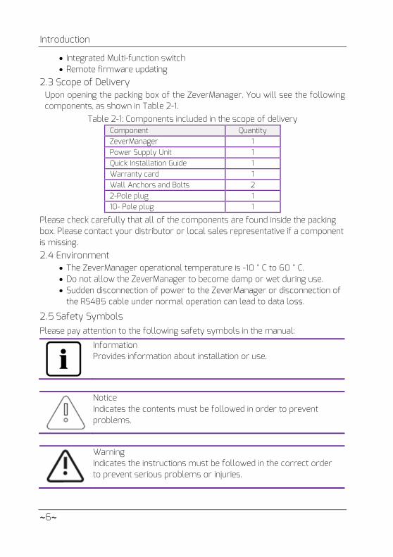
2.3 Scope of Delivery Upon opening the packing box of the ZeverManager. You will see the following components, as shown in Table 2-1.
Table 2-1: Components included in the scope of delivery Component Quantity ZeverManager 1 Power Supply Unit 1 Quick Installation Guide 1 Warranty card 1 Wall Anchors and Bolts 2 2-Pole plug 1 10- Pole plug 1
Please check carefully that all of the components are found inside the packing box. Please contact your distributor or local sales representative if a component is missing. 2.4 Environment
• The ZeverManager operational temperature is -10 ° C to 60 ° C. • Do not allow the ZeverManager to become damp or wet during use. • Sudden disconnection of power to the ZeverManager or disconnection of
the RS485 cable under normal operation can lead to data loss.
2.5 Safety Symbols Please pay attention to the following safety symbols in the manual:
Information Provides information about installation or use.
Notice Indicates the contents must be followed in order to prevent problems.
Warning Indicates the instructions must be followed in the correct order to prevent serious problems or injuries.

Indication
~ 7 ~
3. Indication
3.1 LED Indication ZeverManager displays the operating status to the user via LEDs. The LED indicator panel is showed in Fig.3-1.
Fig. 3-1: LED indicator panel
The meanings of the LEDs are shown in the following Table 3-1.
Table 3-1: LED overview LED Status Explanation
Glowing Green Power on Off Power off
Flashing Red ZeverManager is sending active power limitation instructions
Flashing Green ZeverManager is sending reactive power instructions
Flashing Green ZeverManager is sending data to the inverter Flashing Red ZeverManager is receiving data from the
inverter

Indication
~8~
3.2 LCD Indication
The LCD of the ZeverManager displays information to the user, for example the status of the ZeverManager, IP address, date & time, ZeverManager’s software version. The normal information shown on the LCD is described in table 3-2
Table 3-2: Information screens shown on the LCD display LCD display Description
ZeverManager’s IP address, time and date.
ZeverManager is not connected to the Zevercloud.
ZeverManager is connected to the Zevercloud.
ZeverManager’s software version.
“Total INV 05” is the total number of inverters connected to the ZeverManager since the ZeverManager was powered on,
“Online INV 03” is the number of inverters being currently monitored by the ZeverManager.
Please refer to section “8.3 LCD Indication” for further information.
Installation
~ 9 ~
4. Installation
4.1 Location The ZeverManager should be installed indoors as extreme temperatures, immersing in water, fire and strong impacts will damage the ZeverManager.
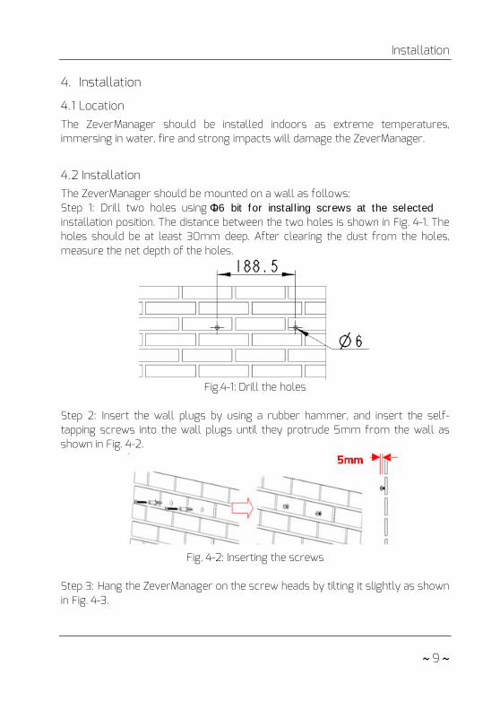
4.2 Installation The ZeverManager should be mounted on a wall as follows: Step 1: Drill two holes using a Φ6 bit for installing screws at the selected installation position. The distance between the two holes is shown in Fig. 4-1. The holes should be at least 30mm deep. After clearing the dust from the holes, measure the net depth of the holes.
Fig.4-1: Drill the holes
Step 2: Insert the wall plugs by using a rubber hammer, and insert the self-tapping screws into the wall plugs until they protrude 5mm from the wall as shown in Fig. 4-2.
Fig. 4-2: Inserting the screws
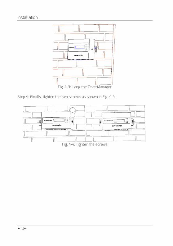
Step 3: Hang the ZeverManager on the screw heads by tilting it slightly as shown in Fig. 4-3.
Installation
~10~
Fig. 4-3: Hang the ZeverManager
Step 4: Finally, tighten the two screws as shown in Fig. 4-4.
Fig. 4-4: Tighten the screws

Connection
~ 11 ~
5. Connection The ZeverManager is a gateway which connects the inverter with the Zevercloud via Ethernet. This section explains how to set up the connection between the Zevercloud and the ZeverManager, as well as the connection between the ZeverManager and the inverters.
5.1 Preparation Before starting, cables need to be prepared as shown in Table 5-1.
Table 5-1: Preparation before starting
Wire Usage Requirement Maximum length
Network cable
Used for connection of ZeverManager with router
1. The wire sequence is according to the EIA/TIA 568 standard.
2. The cable must be CAT-5E or better and UV resistant, if used outdoors.
100m
RS485 cable
Used for connection of ZeverManager with inverter and energy meter.
1. The wire sequence is according to the EIA/TIA 568 standard.
2. The cable must be CAT-5E or better STP (shielded twisted pair).
3. If the cable is used outdoors, it must be UV resistant.
1000m
5-core cable
Used for connection of ZeverManager with RRCR.
5-core wire, diameter of each core is between AWG24-AWG16.
3m
Multi-function switch
Used for connection of ZeverManager with external switch
1. The maximum switching voltage is 60Vdc and the maximum switching current is 1A.
2. The default status of the switch is off
If you use the power control function of the ZeverManager, you should connect the ZeverManager to the RRCR via a 5-core wire and set the ZeverManager to master mode.

Connection
~12~
5.2 Connection Area
Fig. 5-1 shows the connection interfaces of the ZeverManager to other devices.
Fig. 5-1: Connection area
The function of each interface in Fig. 5-1 is shown in Table 5-2.
Table 5-2: Interface function description Port Label Description Function
A USB Micro USB interface Connect to PC for maintenance purposes
B DI. Digital input interface Connect to RRCR C NET Ethernet interface Connect to router D RS485-1 RS485 interface Connect to energy meter or
others E RS485-2 RS485 interface Connect to inverter F DO. Digital output interface Multi-function switch G Power Power interface Connect to power Supply Unit
5.3 Connecting to the Inverter This section describes how to connect the ZeverManager to the inverters: Step 1: For PV Plants with more than one inverter, connect each inverter in a daisy chain configuration with an RS485 cable.shown in Fig. 5-2.
Step 2: Connect the inverter closest to the RS485 port of the ZeverManager (port E in Fig. 5-1) as shown in Fig. 5-2.

Connection
~ 13 ~
Fig. 5-2: Connect with the inverter
The pin order of the RJ45 socket and plug used by the RS485-2 port of the ZeverManager is shown in Fig. 5-3.
Fig. 5-3: Socket and plug definition of RJ45
The RS485-2 pin assignment of the RJ45 socket is shown in Table 5-3.
Table 5-3: RJ45 pin assignment Pin Signal description 1 RX+ 2 RX- 3 TX+ 4 NC 5 NC 6 TX- 7 NC 8 NC
5.4 Connecting to the Network ZeverManager requires an internet connection in order to provide remote monitoring. The connection between the ZeverManager and the Ethernet is shown in Fig. 5-4.
1. The RS485-2 port between the ZeverManager and the inverter (port E in Fig. 5-1) uses the RJ45 socket. Please make sure to use the correct port.
2. The maximum communication distance of the whole RS485 bus is 1000m. Communication quality beyond this length is not guaranteed and can also be influenced by the quality of the RS485 cable.
Connection
~14~
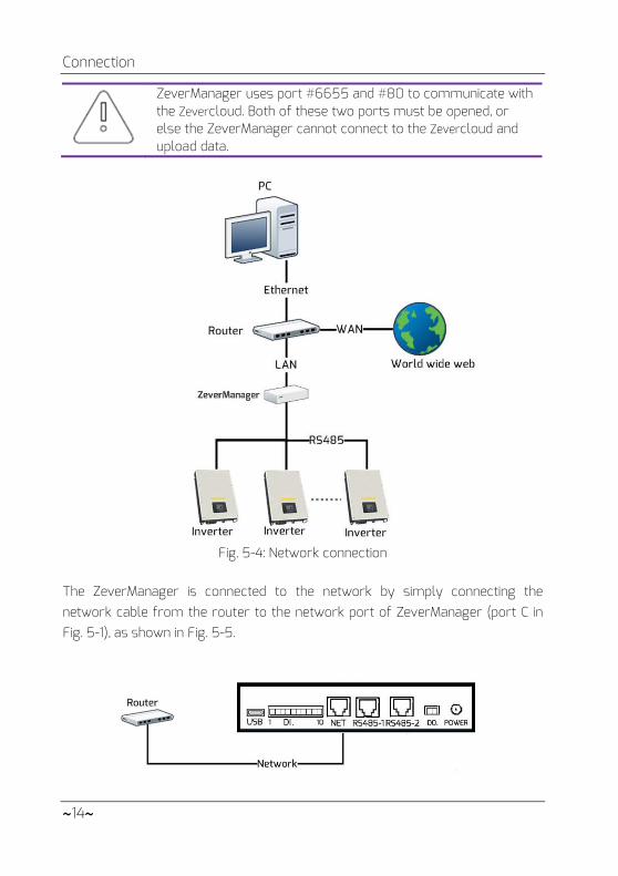
ZeverManager uses port #6655 and #80 to communicate with the Zevercloud. Both of these two ports must be opened, or else the ZeverManager cannot connect to the Zevercloud and upload data.
Fig. 5-4: Network connection
The ZeverManager is connected to the network by simply connecting the network cable from the router to the network port of ZeverManager (port C in Fig. 5-1), as shown in Fig. 5-5.

Connection
~ 15 ~
Fig. 5-5: ZeverManager linked network The ZeverManager obtains an IP address from the router via DHCP automatically and displays it on the LCD. The time it takes to connect to the network depends on the network communication conditions.
The router needs to support DHCP services therefore DHCP services must be activated.
If the IP address of the ZeverManager is different from the network segment assigned by the router, then the ZeverManager did not obtain the correct IP address from the router.
Troubleshooting methods:
1. Make sure the DHCP service of router has been activated. 2. Check the connection between the ZeverManager and the
router. 3. If the ZeverManager cannot obtain an IP address from the
router, the ZeverManager will use 169.254.*.*(* symbol is a random number) as the default IP address. In this case the LCD of the ZeverManager will display 169.254.*.* as the IP address.
5.5 Connecting to the RRCR The ZeverManager must be set to master mode when it is connected to the RRCR. In this way the power control instructions can be sent from the grid operator to the inverters to achieve active power and reactive power limitation. The system connection is showed in Fig. 5-6.
Fig. 5-6: ZeverManager connects directly to the inverters

Connection
~16~
One ZeverManager can connect to up to 50 inverters. If more than 50 inverters are connected, another ZeverManager must be added to the system. The ZeverManager is connected directly to the RRCR and must be set to master mode, and the other ZeverManagers must be set to slave mode. Please refer to section “6.8 Power Management” for instructions to set the mode. The system connection is shown in Fig. 5-7.
Fig. 5-7: Multiple ZeverManagers connected to the inverters
The RRCR is connected to the DI. port of the ZeverManager (port C in Fig. 5-1), as shown in Fig. 5-8.
Fig. 5-8: Connect to RRCR
Pin order of the 10-pin connector is showed in Fig. 5-9.
Fig. 5-9: Pin order of the 10-pin connector
Connection
~ 17 ~
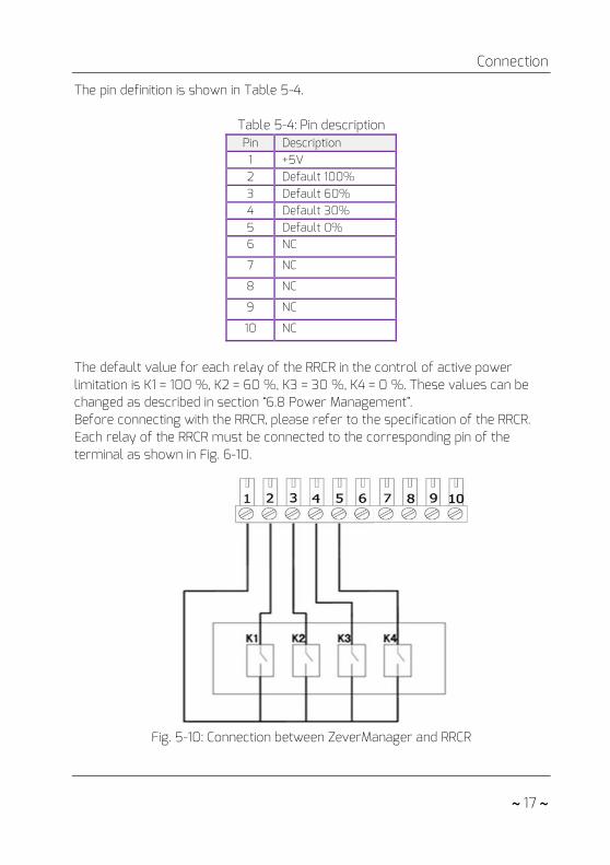
The pin definition is shown in Table 5-4.
Table 5-4: Pin description Pin Description 1 +5V 2 Default 100% 3 Default 60% 4 Default 30% 5 Default 0% 6 NC
7 NC
8 NC
9 NC
10 NC
The default value for each relay of the RRCR in the control of active power limitation is K1 = 100 %, K2 = 60 %, K3 = 30 %, K4 = 0 %. These values can be changed as described in section “6.8 Power Management”. Before connecting with the RRCR, please refer to the specification of the RRCR. Each relay of the RRCR must be connected to the corresponding pin of the terminal as shown in Fig. 6-10.
Fig. 5-10: Connection between ZeverManager and RRCR

Connection
~18~
1. The ZeverManager must only be connected to an RRCR by certified electricians. Wrong connections may destroy the ZeverManager or the RRCR.
2. Please read the RRCR manual carefully before connecting.
5.6 Connecting to the Power Connect the power adapter from the box to the Power Port (port G in Fig. 5-1). Plug the other end into a power outlet, check that the green LED (Power) illuminates as shown in Fig. 3-1.
1. If another adapter is used, please confirm that the adapter complies with the EU low-voltage electrical appliances guideline and the EMC guideline.
2. If another adapter is used, please confirm that the output voltage is 7.5V~12V and the output current not less than 500mA
3. DC output polarity .
5.7 Connecting to the Multi-function Switch ZeverManager is equipped with a multi-function switch, it is a controlled relay which can be used as alarm output or used to control, different types of devices (light, sound, etc). An external voltage is required. The default status of the relay is open which can be connected with normally open contact. When using this function it should comply with the following requirements: Maximum Voltage:60Vdc Maximum Current:1Adc External cable diameter: from 5mm to 17mm Conductor cross-sectional area: from 0.14mm2 to 1.5mm2
If for example there is an inverter error or if the E-Today and total Pac reaches the set value, the switch will close. The relay close condition can be configured by the web server (refer to 6.7). The connection diagram is as shown in Fig. 5-12.

Connection
~ 19 ~
Fig. 5-12: Connection between ZeverManager and Switch
5.8 Connecting to the energy meter ZeverManager can connect to an energy meter for monitoring export power of plant, which can be used for active power limitation. The ZeverManager support the energy meter mode is SMART MINI POWER SDM630DC of ESTRON, the energy meter wiring ways refer to the SMART MIN POWER SDM630DC “USER MANUAL 2013 V1.1”, please. The energy meter must be connected the grid connection point, as shown in Fig. 5-13.
Fig. 5-13: Connect with the energy meter
The energy meter connected to RS485-1 port of ZeverManager (port D in Fig. 5-1), as shown in Fig. 5-14.

Connection
~20~
Fig.5-14: Connection Energy Meter
The pin order of the RJ45 socket and plug used by the RS485-1 port of the ZeverManager is shown in Fig. 5-15.
Fig. 5-15: Socket and plug definition of RJ45
The RS485-1 pin assignment of the RJ45 socket is shown in Table 5-4.
Table 5-4: RJ45 pin assignment Pin Signal description 1 A 2 B 3 NC 4 NC 5 NC 6 NC 7 NC 8 NC
How to setting parameters, please refer to “Active Power Limitation mode” of “6.8 Power Management”
1. The RS485-1 port between the ZeverManager and the energy meter (port D in Fig. 5-1) uses the RJ45 socket. Please make sure to use the correct port.
2. The maximum communication distance of the whole RS485 bus is 1000m. Communication quality beyond this length is not guaranteed and can also be influenced by the quality of the RS485 cable.
Web Server
~ 21 ~
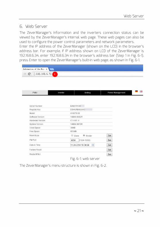
6. Web Server The ZeverManager’s Information and the inverters connection status can be viewed by the ZeverManager’s internal web page. These web pages can also be used to configure the power control parameters and network parameters. Enter the IP address of the ZeverManager (shown on the LCD) in the browser’s address bar. For example, if IP address shown on LCD of the ZeverManager is 192.168.6.34, enter 192.168.6.34 in the browser’s address bar (Step 1 in Fig. 6-1), press Enter to open the ZeverManager’s built-in web page, as shown in Fig. 6-1.
Fig. 6-1: web server
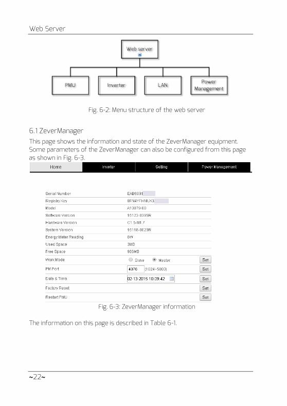
The ZeverManager’s menu structure is shown in Fig. 6-2.
Web Server
~22~
Fig. 6-2: Menu structure of the web server
6.1 ZeverManager This page shows the information and state of the ZeverManager equipment. Some parameters of the ZeverManager can also be configured from this page as shown in Fig. 6-3.
Fig. 6-3: ZeverManager information
The information on this page is described in Table 6-1.

Web Server
~ 23 ~
Table 6-1: Description of ZeverManager page
Object Description Serial Number A unique identifier to distinguish the ZeverManager.
Registry Key Registry key of the ZeverManager used to create the PV plant in Zevercloud.
Model ZeverManager model. Software Version Software version of the ZeverManager. Hardware Version Hardware version of the ZeverManager. Energy Meter Reading The value of energy meter reading. Used Space Used space of internal memory of the ZeverManager. Free Space Free space of internal memory of the ZeverManager. Work Mode Master/slave mode, refer to 6.2.
PM Port Power control port of the ZeverManager, refer to 6.3.
Date & Time The current date and time of the ZeverManager. Factory Reset Factory Reset, refer to 6.4. Restart ZeverManager Restart ZeverManager, refer to 6.5.
6.2 Work Mode The ZeverManager has master and slave modes, the main distinction is that master mode is used when the power management functions are needed. In master mode, the ZeverManager can receive power control instructions from an external RRCR and send the instructions to the inverters and other slave ZeverManagers in the same network segment. In slave mode, the ZeverManager cannot receive power control instructions directly from an external RRCR, but only from the master ZeverManager in the same network segment. The slave ZeverManager will send the instructions to the inverters it is connected to. The method of setting the ZeverManager work mode is showed in Fig. 6-4. After selecting the mode, click on “Set” and wait for approximately three minutes. The ZeverManager will restart automatically. Refresh the page in the browser manually in order to see the modified information.
Fig. 6-4: Work mode of ZeverManager

Web Server
~24~
1. After the work mode has been successfully changed, the ZeverManager needs approximately three minutes to restart.
2. The PM Port of the slave ZeverManager must be the same as the master ZeverManager in the same network segment, in order to receive power control instructions from the master ZeverManager. Refer to PM Port in section 6.2.
3. Slave mode is the default mode of the ZeverManager.
6.3 PM Port It is possible to have more than one master ZeverManager in the same network segment, however to avoid interference of power control instructions, the PM Ports must be set to different values. As shown in Fig. 6-5, the router is connected to four ZeverManagers at the same time, the two ZeverManagers on the left side are set to master mode and slave mode respectively, and their PM Ports are set to 3000, while the two ZeverManagers on the right side are set to master mode and slave mode as well with their PM Ports set to 4000. In this way ZeverManager 1 can only receive power control instructions from ZeverManager 2, and ZeverManager 4 can only receive power control instructions from ZeverManager 3
.
Fig. 6-5: ZeverManagers under master mode achieve power control

Web Server
~ 25 ~
After the PM Port is changed successfully, the ZeverManager will restart automatically in 3minutes.
6.4 Factory Reset If a factory reset is performed, all the user data will be cleared and will not be recoverable. After the reset, the ZeverManager will restart automatically in three minutes.
6.5 Restart ZeverManager Click the “Set” button at the Restart, ZeverManager will restart automatically in three minutes.
6.6 Inverter Click “Inverter” menu and the inverter information page will be opened as shown in Fig. 6-6. This page displays the information of all the inverters connected to the ZeverManager since it was started, including serial number, status, mode, E-Today and E-Total. When “Status” is “Online”, it means that the inverter is currently being monitored by the ZeverManager. When “Status” is “Offline” it means that the inverter is not being currently monitored as shown in Fig. 6-6.
Fig. 6-6: Information of inverter
If the inverter works normally and is connected to the ZeverManager with an RS485 cable and the “Status” is “Offline”, it means that the inverter is not being monitored by the ZeverManager. Please check in as following: 1. Whether is there problem with the RS485 cable 2. Whether is the ZeverManager work normally
Web Server
~26~
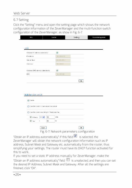
6.7 Setting Click the “Setting” menu and open the setting page which shows the network configuration information of the ZeverManager and the multi-function switch configuration of the ZeverManager, as show in Fig. 6-7
Fig. 6-7: Network parameters configuration
“Obtain an IP address automatically”: if this field is selected, the ZeverManager will obtain the network configuration information such as IP address, Subnet Mask and Gateway etc. automatically from the router, thus simplifying your settings. The router must have its DHCP function activated for this to work. If you need to set a static IP address manually for ZeverManager, make the
“Obtain an IP address automatically” field is unselected, and then you can set the desired IP Address, Subnet Mask and Gateway. After all the settings are finished, click “OK”.
Web Server
~ 27 ~
“Obtain a DNS address automatically”: if this field is selected, the ZeverManager will obtain the network configuration information such as DNS address, automatically from the router, thus simplifying your settings. The router must have its DHCP function activated for this to work. If you need to set a static DNS address manually for ZeverManager, make the “Obtain a DNS address automatically” field is unselected, and then you can enter a desired DNS Address. After all the settings are finished, click “OK”.
To allow the ZeverManager to obtain an IP address automatically, the DHCP function of the router connected to the ZeverManager must be activated.
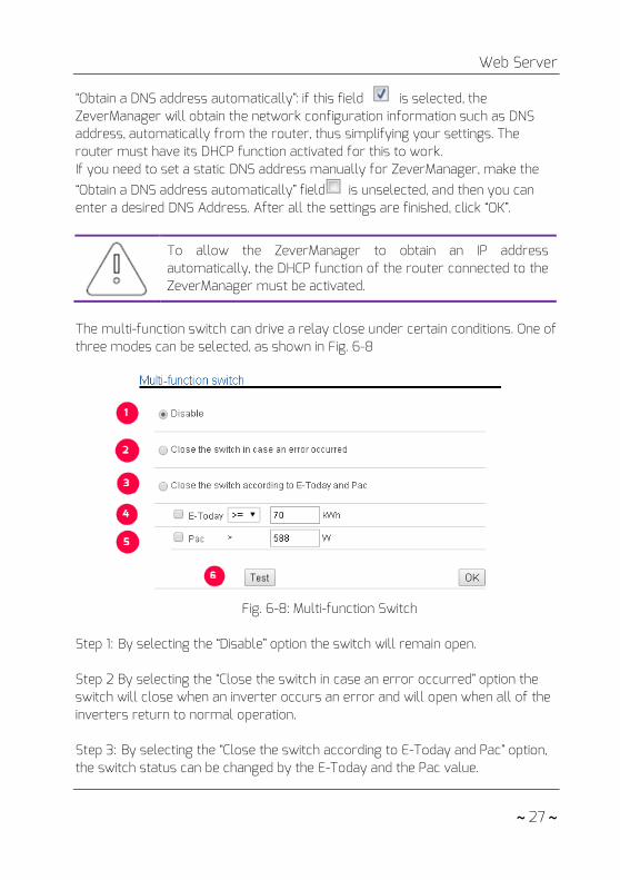
The multi-function switch can drive a relay close under certain conditions. One of three modes can be selected, as shown in Fig. 6-8
Fig. 6-8: Multi-function Switch
Step 1: By selecting the “Disable” option the switch will remain open. Step 2 By selecting the “Close the switch in case an error occurred” option the switch will close when an inverter occurs an error and will open when all of the inverters return to normal operation. Step 3: By selecting the “Close the switch according to E-Today and Pac” option, the switch status can be changed by the E-Today and the Pac value.

Web Server
~28~
Step 4: The switch status will be immediately change when the E-Today reaches the set value. Step 5: The switch status will change immediately when the Pac value reaches the set value its status will be changed if the Pac value is on for more than ten minutes. Step 6: By clicking on the “Test” button, the switch will open and close ten times.
Only one of the three modes can be selected at any one time (Disable, Close the switch in case an error occurred, Close the switch according to E-Today and Pac.)
6.8 Power Management Both the EEG and BDEW regulations require power management functions to be enabled for the PV plant. The ZeverManager can receive power control instructions from the RRCR and will send these instructions to the inverters. This functionality can be set up as follows: Step 1: Set the ZeverManager that is connected to the RRCR to master mode (ZeverManager 1 shown in Fig. 6-9). Additional ZeverManager´s should be set to slave mode (ZeverManager 2 and ZeverManager 3 shown in Fig. 6-9). The PM Port of each ZeverManager must be set to the same value. If the setup is successful, the ZeverManager will restart in 3 minutes.
Fig. 6-9: Use ZeverManagers to achieve power control
Web Server
~ 29 ~
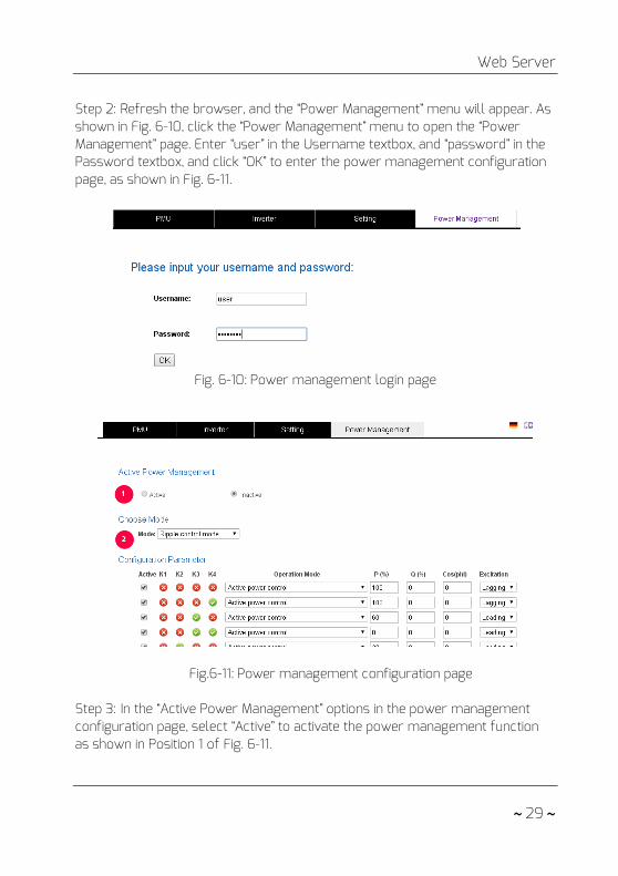
Step 2: Refresh the browser, and the “Power Management” menu will appear. As shown in Fig. 6-10, click the “Power Management” menu to open the “Power Management” page. Enter “user” in the Username textbox, and “password” in the Password textbox, and click “OK” to enter the power management configuration page, as shown in Fig. 6-11.
Fig. 6-10: Power management login page
Fig.6-11: Power management configuration page
Step 3: In the “Active Power Management” options in the power management configuration page, select “Active” to activate the power management function as shown in Position 1 of Fig. 6-11.

Web Server
~30~
After activating this function, the ZeverManager will send the power control instructions to the inverter and to the other slave ZeverManagers in the same network segment (ZeverManager 2 and ZeverManager 3 as shown in Fig. 6-9). The slave ZeverManager will send all the power control instructions to all of the inverters connected to it. Selecting “Inactive” will disable this function and the ZeverManager will not send power control instructions to the inverters.
In the following two conditions, the inverter will work according to the last power control instruction: 1. If the “Active Power Management” is changed from “Active” to
“Inactive”, the ZeverManager will stop sending power control instructions immediately.
2. If the RS485 cable accidentally breaks or the inverter cannot receive new power control instructions because of another problem.
Step 4: Select the mode of power management (as shown in Position 2 of Fig. 6-11) from the “Choose Model” options in the Power Management page. There are six modes of power management and the specific meaning of each working mode is as follows:
• Ripple Control Mode: In this mode, the ZeverManager will send power
control instructions to the inverters according to the status of the RRCR and the settings of the “Configuration Parameter”. The specific operations of “Configuration Parameter” are shown in “Step 5”.
• Cos(phi) fix mode: In this mode, the ZeverManager will regulate the reactive power of inverter according to the Cos(phi) value which is set by the user. Enter the Cos(phi) value and choose the phase in Position 1 of Fig. 6-12.
Fig. 6-12: Cos(phi) fix mode
Web Server
~ 31 ~
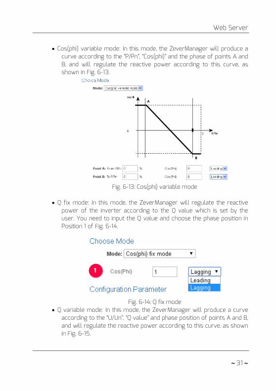
• Cos(phi) variable mode: In this mode, the ZeverManager will produce a
curve according to the “P/Pn”, “Cos(phi)” and the phase of points A and B, and will regulate the reactive power according to this curve, as shown in Fig. 6-13.
Fig. 6-13: Cos(phi) variable mode
• Q fix mode: In this mode, the ZeverManager will regulate the reactive
power of the inverter according to the Q value which is set by the user. You need to input the Q value and choose the phase position in Position 1 of Fig. 6-14.
Fig. 6-14: Q fix mode
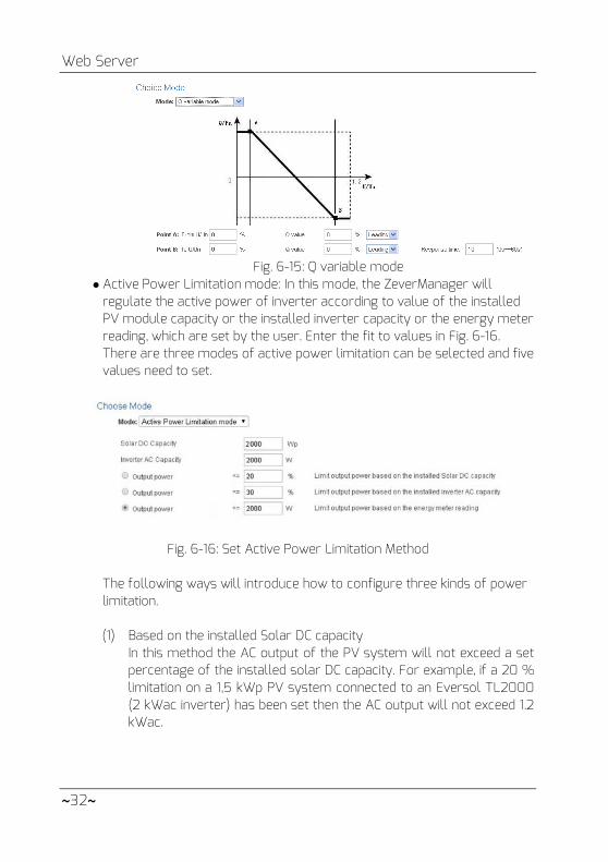
• Q variable mode: In this mode, the ZeverManager will produce a curve according to the “U/Un”, “Q value” and phase position of points A and B, and will regulate the reactive power according to this curve, as shown in Fig. 6-15.
Web Server
~32~
Fig. 6-15: Q variable mode
Active Power Limitation mode: In this mode, the ZeverManager will regulate the active power of inverter according to value of the installed PV module capacity or the installed inverter capacity or the energy meter reading, which are set by the user. Enter the fit to values in Fig. 6-16. There are three modes of active power limitation can be selected and five values need to set.
Fig. 6-16: Set Active Power Limitation Method
The following ways will introduce how to configure three kinds of power limitation. (1) Based on the installed Solar DC capacity
In this method the AC output of the PV system will not exceed a set percentage of the installed solar DC capacity. For example, if a 20 % limitation on a 1,5 kWp PV system connected to an Eversol TL2000 (2 kWac inverter) has been set then the AC output will not exceed 1.2 kWac.

Web Server
~ 33 ~
The Fig.6-17 shows the system diagram of power limitation based on the installed solar DC capacity .
Fig. 6-17 System diagram based on the installed solar DC capacity
For this method position 1 in Fig. 6-18 should be ticked. For correct operation of this method there are three parameters that must be entered, please refer to Fig. 6-18: • Item A – installed solar DC capacity of PV system in Wp; • Item B – total inverter AC capacity of PV system in W; • Item C – Limitation value of solar DC capacity in %. Click “OK” button in bottom-right of this web page to ensure the setting parameters take effect.
The Fig. 6-18 Setting parameters based on the installed solar DC capacity
Web Server
~34~
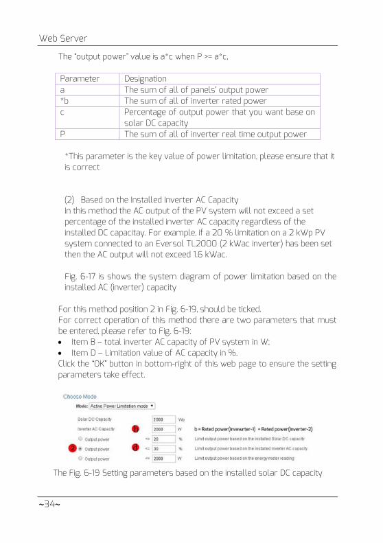
The “output power” value is a*c when P >= a*c, Parameter Designation a The sum of all of panels’ output power *b The sum of all of inverter rated power c Percentage of output power that you want base on
solar DC capacity P The sum of all of inverter real time output power
*This parameter is the key value of power limitation, please ensure that it is correct (2) Based on the Installed Inverter AC Capacity In this method the AC output of the PV system will not exceed a set percentage of the installed inverter AC capacity regardless of the installed DC capacitay. For example, if a 20 % limitation on a 2 kWp PV system connected to an Eversol TL2000 (2 kWac inverter) has been set then the AC output will not exceed 1.6 kWac.
Fig. 6-17 is shows the system diagram of power limitation based on the installed AC (inverter) capacity
For this method position 2 in Fig. 6-19, should be ticked. For correct operation of this method there are two parameters that must be entered, please refer to Fig. 6-19: • Item B – total inverter AC capacity of PV system in W; • Item D – Limitation value of AC capacity in %. Click the “OK” button in bottom-right of this web page to ensure the setting parameters take effect.
The Fig. 6-19 Setting parameters based on the installed solar DC capacity
Web Server
~ 35 ~
The “output power” value is b*d when P >= b*d, Parameter Designation *b The sum of all of inverter rated power d Percentage of power output that you want base on all of
inverter rated power P The sum of all of inverter real time power
*This parameter is the key value of power limitation, please ensure that it is correct
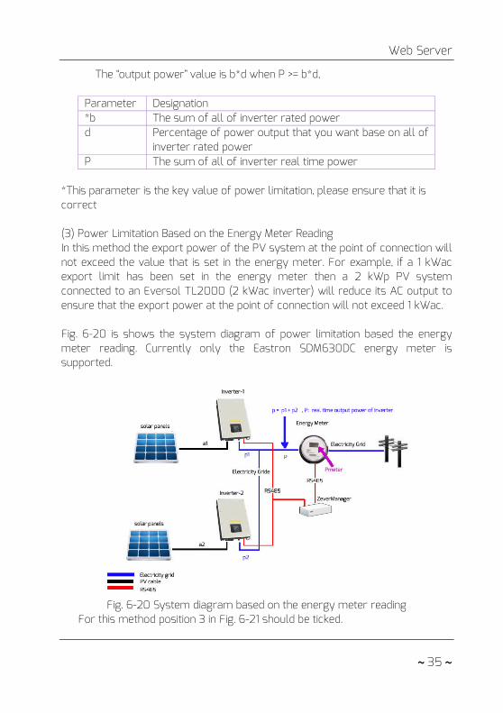
(3) Power Limitation Based on the Energy Meter Reading In this method the export power of the PV system at the point of connection will not exceed the value that is set in the energy meter. For example, if a 1 kWac export limit has been set in the energy meter then a 2 kWp PV system connected to an Eversol TL2000 (2 kWac inverter) will reduce its AC output to ensure that the export power at the point of connection will not exceed 1 kWac.
Fig. 6-20 is shows the system diagram of power limitation based the energy meter reading. Currently only the Eastron SDM630DC energy meter is supported.
Fig. 6-20 System diagram based on the energy meter reading
For this method position 3 in Fig. 6-21 should be ticked.

Web Server
~36~
For correct operation of this method there are two parameters that must be entered, please refer to Fig. 6-21: • Item B – total inverter AC capacity of PV system in W; • Item E – Limitation value of AC capacity in %. Click the “OK” button in bottom-right of this web page to ensure the setting parameters take effect.
The Fig. 6-21 Setting parameters base on the energy meter reading
The “output power” value is e when P >= Pmeter,
Parameter Designation *b The sum of all of inverter rated power e The output power that you want P The sum of all of inverter real time power Pmeter The power of energy meter reading
* This parameter is the key value of power limitation, please ensure that it is correct
In the five modes of Cos(phi) fix mode,Cos(phi) variable mode, Q fix mode, Q variable mode, Fix active power , the ZeverManager does not receive the instructions from the RRCR.
Step 5:K1,K2,K3,K4 represent the four switching signals of the RRCR, this
icon means that the switch is closed. This icon means that the switch is opened. The four switches of the RRCR can combine to provide sixteen different status values each with a corresponding operation mode. Ticking the box means activated, as shown in Fig. 6-22.

Web Server
~ 37 ~
Fig.6-22: Status of configuration
When the ZeverManager is not connected to the RRCR, K1 to K4
will show four , which means that all four switches are disconnected.
After a status is activated, the operating mode can be set. In “Operating Mode” drop down list, a corresponding operating mode can be selected, as shown in Fig.6-23. The meaning of each operating mode is as follows.
Fig. 6-23: Operating mode

Web Server
~38~
• Effective power control:If this mode is selected, the ZeverManager
only regulates the active power P(%) according to the received signals from the RCRR. Therefore only the P(%) value is set, as shown in Fig. 7-24.
Fig. 6-24: Configuration of the value of RRCR active power
• Active power limitation and Q set point:If this mode is selected, the
ZeverManager only regulates the active power P(%) and the Q value according to received signals. Therefore, both the P(%) and the Q values can be set, as shown in Fig.6-25.
Fig. 6-26: Configuration of the value of
RRCR active power and the Q value
• Active power limitation and Cos(phi) set point:If this mode is selected, the ZeverManager only regulates the active power P(%) and the Cos(phi) value according to the received signals. Therefore the P(%)the Cos(phi) value and the phase position can be set, as shown in Fig. 6-27.
Fig. 6-27: Configuration of the value of the RRCR
active power and the Cos(phi) value
Step 6: The Fallback option is used to decide which power control instruction to send when the ZeverManager detects when K1-K4 are invalid. If the Fallback is not activated, then the ZeverManager will not send any power control instructions if it detects that K1-K4 are invalid. In this case the inverters will maintain the status of the previous power control until the inverters restart. If “Fallback” is activated and the ZeverManager detects that K1-K4 are invalid, the ZeverManager will send the power control instructions according to the “Fallback” configuration.

Web Server
~ 39 ~
“Time” means delay time, which means entering the “Fallback” status after waiting a certain period of time. Every time value of the “Fallback” option is changed, the system will restart the timing from 0, as shown in Fig. 6-27.
Fig. 6-27: Configuration of the value of RRCR
active power and Cos(phi) value Step 7: Click the “Save” button and the ZeverManager will save all the configurations of this page and the ZeverManager will manage the power according to the user’s configuration.
1. The corresponding settings of the power management must be operated by qualified engineers. Wrong connection or configuration may destroy the ZeverManager or the RRCR or disrupt the power grid.
2. ZeverManager has sixteen combinations of configurations. For the specific configuration status, please refer to the requirements of the grid operator.
3. The ZeverManager offers five kinds of reactive power requirement modes and two kinds of active power requirement modes, please refer to the requirements of grid operator to determine the required mode.
6.9 Switch language The ZeverManager supports multi-languages you can find the Language button on the top-right corner of every web page. Each flag represents one kind of language, as shown in Fig6-28.
Fig. 6-28: Multi-language flag

Zevercloud
~40~
7. Zevercloud The Zevercloud is a cloud service platform for users provided by Zeversolar. The ZeverManager transfers the operation data to the Zevercloud server via the Internet to enable the users to monitor their PV plants and inverters remotely through a computer or a mobile device.
You can visit Zevercloud via the following website on a PC: http://www.zevercloud.com. For the Android application, search for “Solarcloud” in Google play to download and install Zevercloud for on your mobile device. For the iPhone or iPad application, search for “Solarcloud” in the App store of the Apple Corporation and install it on your iPhone or iPad.
To monitor the PV plant and inverter with Zevercloud, the ZeverManager and Internet must be functioning normally.
7.1 Account Registration Users who use Zevercloud for the first time are required to register an account in Zevercloud. Monitoring can then be performed after the user has registered.
Step 1: Input http://www.zevercloud.com in the browser and open the main page of Zevercloud as shown in Fig. 7-1.
Fig. 7-1: Registration and login page

Zevercloud
~ 41 ~
Step 2: Click the button marked with a “1” in Fig .7-1, click “CREATE AN ACCOUNT” to enter the registration page, and register a user account according to the prompts.
Step 3: After the registration has been completed, Zevercloud will send an activation email. Activate your Zevercloud account according to the information in the email. If there is no activation mail in your inbox, please check your spam box.
If you did not receive an email from Zevercloud, it could be: 1. The email was identified as junk mail. Please check the spam
folder. If the email from Zevercloud was identified as junk mail, please add the address of Zevercloud into your white list to avoid future emails from Zevercloud being identified as junk mail.
2. You may have input an email address which is different from the one you used for registration. Please confirm if the email was sent to another email address. Please reregister if you entered an unknown email address when entering account information.
7.2 Create a PV plant Step1: Enter http://www.zevercloud.com in the address bar of the browser and open the home page of Zevercloud as shown in Fig. 7-1.
Step2: Input your user name and password in the area marked with a “1” in Fig. 7-1 to login to Zevercloud. If the login is successful you will enter the web page with a PV plant list as shown in Fig. 7-2.
Fig. 7-2: Setting up a new PV plant

Zevercloud
~42~
Step3: Click Position 1 in Fig. 7-2 to enter the PV plant establishing page as shown in Fig. 7-3. Follow the prompts on the page to establish a PV plant.
Fig. 7-3: Enter the ZeverManager and PV plant information
to finish the creation of PV plant
During PV plant creation, it is very important to choose the correct time zone. Please select the correct time zone where the PV plant is located in Position 4 shown in Fig. 7-3.
When establishing a PV plant, it is necessary to input the serial number and registry number of the ZeverManager. This information can be found on the ZeverManager label.
7.3 Browse PV plant You can enter any PV plant by clicking the plant list. This allows you to view the power generation data of the PV plant as well as inverter events. The menu structure is shown in Fig. 7-4:
Fig. 7-4: Menu structure of PV plant monitor page
Zevercloud
~ 43 ~
7.3.1 Overview This menu provides information such as E-Today, E-Total and the Yield of the entire PV plant. It also provides the power generation graph of the PV plant.
7.3.2 Power & Energy This menu provides detailed graphs such as power & energy of each inverter in the PV plant.
7.3.3 Input This menu provides detailed graphs such as Input PV Vpv & Ipv of each inverter in the PV plant.
7.3.4 Output This menu provides detailed graphs such as Vac, Iac & Fac of each inverter in the PV plant.
7.3.5 Co2 Avoided & Income This menu provides detailed graphs such as Co2 Avoided & Income.
7.3.6 Event This menu provides detailed information of each inverter’s work state.
7.4 Add a ZeverManager A ZeverManager can be added to a PV plant as follows: Step1: Login to Zevercloud and enter Configuration→Device Managem ent page. Step2: Enter the serial number and registry key of the ZeverManager into the textbox shown in Fig. 7-5.
Fig. 7-5: Add more ZeverManagers to the PV plant
Step3: Click the “Add monitor” button and the new ZeverManager will be added.
Zevercloud
~44~
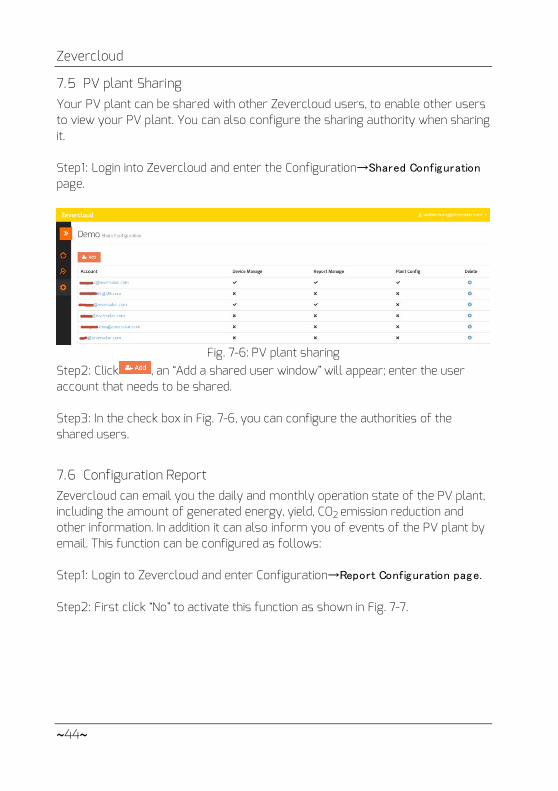
7.5 PV plant Sharing Your PV plant can be shared with other Zevercloud users, to enable other users to view your PV plant. You can also configure the sharing authority when sharing it.
Step1: Login into Zevercloud and enter the Configuration→Shared Configuration
page.
Fig. 7-6: PV plant sharing
Step2: Click , an “Add a shared user window” will appear; enter the user account that needs to be shared. Step3: In the check box in Fig. 7-6, you can configure the authorities of the shared users.
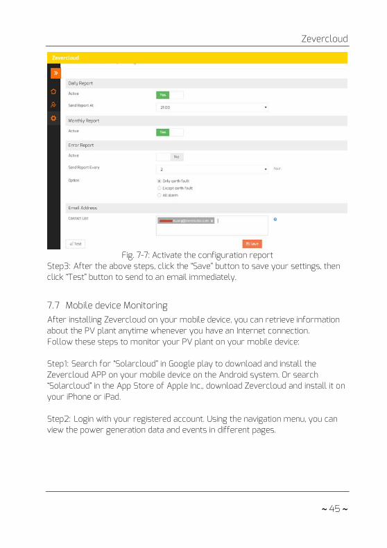
7.6 Configuration Report Zevercloud can email you the daily and monthly operation state of the PV plant, including the amount of generated energy, yield, CO2 emission reduction and other information. In addition it can also inform you of events of the PV plant by email. This function can be configured as follows:
Step1: Login to Zevercloud and enter Configuration→Report Configuration page. Step2: First click “No” to activate this function as shown in Fig. 7-7.
Zevercloud
~ 45 ~
Fig. 7-7: Activate the configuration report
Step3: After the above steps, click the “Save” button to save your settings, then click “Test” button to send to an email immediately.
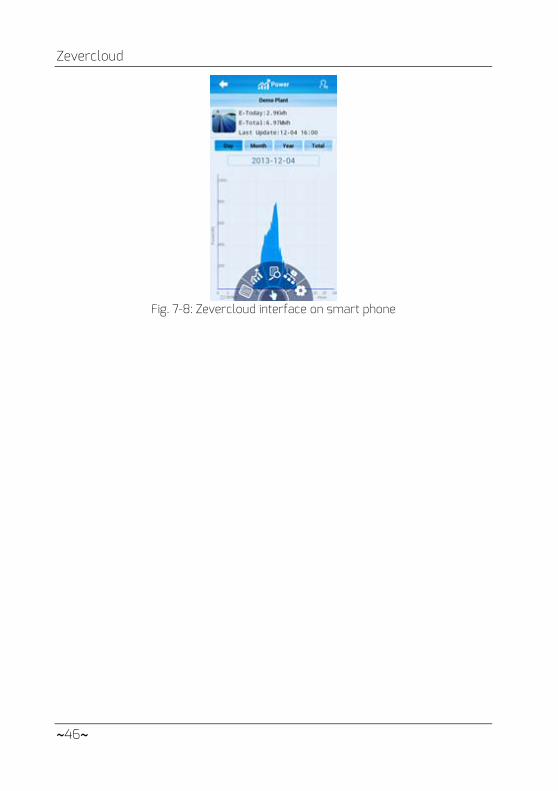
7.7 Mobile device Monitoring After installing Zevercloud on your mobile device, you can retrieve information about the PV plant anytime whenever you have an Internet connection. Follow these steps to monitor your PV plant on your mobile device:
Step1: Search for “Solarcloud” in Google play to download and install the Zevercloud APP on your mobile device on the Android system. Or search “Solarcloud” in the App Store of Apple Inc., download Zevercloud and install it on your iPhone or iPad.
Step2: Login with your registered account. Using the navigation menu, you can view the power generation data and events in different pages.
Zevercloud
~46~
Fig. 7-8: Zevercloud interface on smart phone

Trouble Shooting
~ 47 ~
8. Trouble Shooting
8.1 LED Indication Some faults can be identified by looking at the LEDs.
LED Status Description Solutions
Off
Power supply is abnormal
Check the power supply. Ensure the power supply of the power outlet is normal
Green Off System error Restart ZeverManager Red light does not flash after green light flashed
Inverter has not sent data to the ZeverManager
Check that the connection cable between the inverter and ZeverManager is not damaged or disconnected
8.2 LED Indication of Network Interface
LED Status Description Solutions
Yellow light(link)
Off No connection established
Check whether the connection between the router and ZeverManager is normal, make sure the router is turned on
On Connection established
NA
Green light (activity)
Off Communication is abnormal
Check whether the connections between router/switch and ZeverManager are normal.
Flashing Data is being transmitted or received
NA
8.3 LCD Indication The LCD display information of the ZeverManager can help with trouble shooting as follows: Display Solutions
Login TimeoutZevercloud
The ZeverManager cannot connect to the Zevercloud. Please resolve the connection issue between the ZeverManager and

Trouble Shooting
~48~
the internet.
The ZeverManager cannot be connected with Zevercloud. Please debug the connection problem between the ZeverManager and the internet.
The inverter connected to the ZeverManager has no serial number. Please contact our after-sales service personnel.
The inverter serial number is invalid. Please contact our after-sales service personnel.
The serial number of the inverter connected to the ZeverManager is blank. Please contact our after-sales service personnel.
Confirm whether the SN on the label of ZeverManager is the same as that displayed in the built-in Web server. If not, please contact our after-sales service personnel.
PMU UnbindZevercloud
The ZeverManager is not added to your plant in Zevercloud. Please add the ZeverManager into your plan as described in section 7.4.
Login SelfZevercloud
Please contact our after-sales service personnel.
Login OtherZevercloud
Please contact our after-sales service personnel.
Login UnknowZevercloud
Please contact our after-sales service personnel.
Five inverters connected to the ZeverManager are not being monitored. Check whether the RS485 cable is connected or restart the ZeverManager.
The IP address shown in ZeverManager is not in the same network segment with the IP address distributed by the router.
1. Confirm whether the internet cable connection between the ZeverManager and the router is normal.
2. Confirm whether the DHCP of the Router is activated. 3. Restart the ZeverManager.
The time displayed on the LCD of the ZeverManager is incorrect.
Adjust the time zone of PV plant in Zevercloud to the time zone you are in.
8.4 FAQ
Trouble Shooting
~ 49 ~
Q1. How can I confirm whether all the inverters are connected to the ZeverManager? Method 1: Check the LCD on the ZeverManager. The “Online INV*”on the LCD of ZeverManager shows the number of inverters currently being monitored. Check whether this number is the same as the number of inverters connected to this ZeverManager through the RS485 cable. Method 2: In the Inverter menu of built-in web server in the ZeverManager, check whether the number of online ZeverManagers is the same as the number of inverters connected to the ZeverManager. Refer to section 6.2. Q2. How can I confirm whether the ZeverManager is successfully connected to Zevercloud? Check the LCD display on the ZeverManager. If it shows “Connected Solarcloud”, it means the ZeverManager is successfully connected to Zevercloud. “Disconnected Solarcloud” means the ZeverManager is disconnected from Zevercloud. Q3. Why can’t I open the web page of the ZeverManager’s web server? Check whether the IP address displayed on the LCD of ZeverManager and the IP address of the computer are in the same network segment. If not, please use a computer that is in the same network segment with the ZeverManager to login.

Technical Parameters
~50~
9. Technical Parameters
Electrical Data Power supply DC: 7.5~12V
Max. power consumption 2.5W Communication Communicate with the inverter 4-wires RS485 Communicate with the Energy Meter 2-wires RS485 Communicate with router Ethernet Number of directly connected inverters Max.50 The number of connected ZeverManager
Max.10
Interface DI. 4 digital input ports (for RRCR) Ethernet 10/100 Mbit/s, RJ45 (for Router)
RS485 4-wires RS485 2-wires
USB Micro USB (for Debug)
DO. 1 digital output
Max. communication range RS485 1000 m Ethernet 100 m Power Manager 3 m Mechanical data Dimensions (W x H x D) in mm 172.5x31x102.5 mm Weight 350g Installation Wall, Indoor Environmental conditions Operation -10℃ to +60℃ Storage and shipment -30℃ to +80℃ Relative air humidity 5% to 90%, non-condensing Protection class IP20

Disposal
~ 51 ~
10. Disposal This symbol on the product or on its packaging indicates that this product must not be disposed of with your other household waste. Instead, it is your responsibility to dispose of your old equipment by handing it over to a designated collection point for the recycling of waste electrical and electronic
equipment. The separate collection and recycling of your waste equipment at the time of disposal will help to conserve natural resources and ensure that it is recycled in a manner that protects human health and the environment. For more information about where you can drop off your waste equipment for recycling, please contact your local city office, your household waste disposal service or the shop where you purchased the product.

Contact us
~52~
11. Contact us
If you have any technical problems concerning our products, please contact
Zeversolar service.
SMA New Energy Technology (Jiangsu) Co., Ltd
Tel.: +86 512 6937 0998
Fax: +86 512 6937 3159
E-mail: [email protected]
Factory add.: No.588 Gangxing Road, Yangzhong Jiangsu, China
Headquarters add.: Building 9 No.198 Xiangyang Road, Suzhou 215011, China