user's manual model zr22g, zr402g separate type...
TRANSCRIPT

User'sManual
IM 11M12A01-02E
Model ZR22G, ZR402G
Separate type
Zirconia Oxygen Analyzer
IM 11M12A01-02E7th Edition
iIM 11M12A01-02E
IM 11M12A01-02E7th Edition: Sep. 2006 (YK)All Rights Reserved, Copyright © 2000, Yokogawa Electric Corporation
Introduction
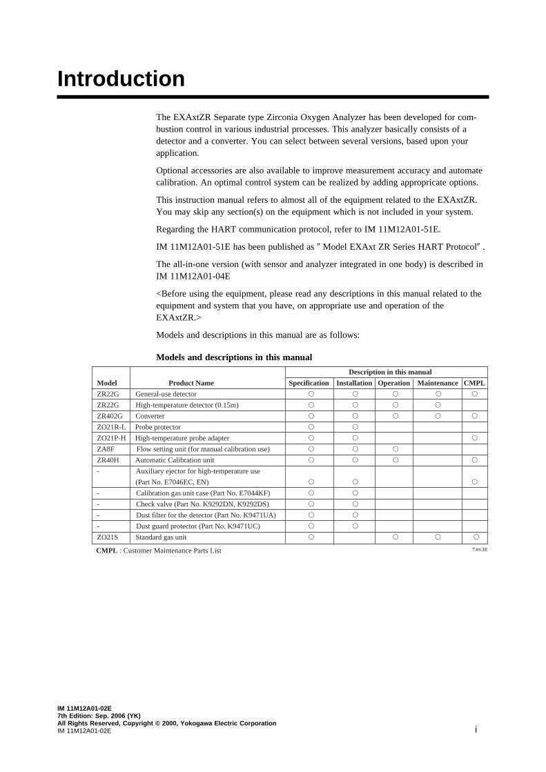
The EXAxtZR Separate type Zirconia Oxygen Analyzer has been developed for com-bustion control in various industrial processes. This analyzer basically consists of adetector and a converter. You can select between several versions, based upon yourapplication.
Optional accessories are also available to improve measurement accuracy and automatecalibration. An optimal control system can be realized by adding appropricate options.
This instruction manual refers to almost all of the equipment related to the EXAxtZR.You may skip any section(s) on the equipment which is not included in your system.
Regarding the HART communication protocol, refer to IM 11M12A01-51E.
IM 11M12A01-51E has been published as 0 Model EXAxt ZR Series HART Protocol0 .
The all-in-one version (with sensor and analyzer integrated in one body) is described inIM 11M12A01-04E
<Before using the equipment, please read any descriptions in this manual related to theequipment and system that you have, on appropriate use and operation of theEXAxtZR.>
Models and descriptions in this manual are as follows:
Models and descriptions in this manual
Description in this manual
Model Product Name Specification Installation Operation Maintenance CMPL
ZR22G General-use detector s s s s s
ZR22G High-temperature detector (0.15m) s s s s
ZR402G Converter s s s s s
ZO21R-L Probe protector s s
ZO21P-H High-temperature probe adapter s s s
ZA8F Flow setting unit (for manual calibration use) s s s
ZR40H Automatic Calibration unit s s s s
- Auxiliary ejector for high-temperature use
(Part No. E7046EC, EN) s s s
- Calibration gas unit case (Part No. E7044KF) s s
- Check valve (Part No. K9292DN, K9292DS) s s
- Dust filter for the detector (Part No. K9471UA) s s
- Dust guard protector (Part No. K9471UC) s s
ZO21S Standard gas unit s s s s
T.Int.1ECMPL : Customer Maintenance Parts List
IM 1M12A01-02Eii
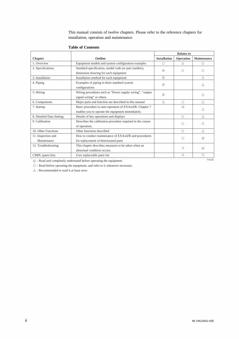
This manual consists of twelve chapters. Please refer to the reference chapters forinstallation, operation and maintenance.
Table of Contents
T.Int.2E
s
s
s
s
n
s
s
s
n
n
n
n
n
n
n
s
s
s
s
s
s
s
Relates to
Chapter Outline Installation Operation Maintenance
1. Overview Equipment models and system configuration examples
2. Specifications Standard specification, model code (or part number),
dimension drawing for each equipment
3. Installation Installation method for each equipment
4. Piping Examples of piping in three standard system
configurations
5. Wiring Wiring procedures such as “Power supply wiring”, “output
signal wiring” or others
6. Components Major parts and function are described in this manual
7. Startup Basic procedure to start operation of EXAxtZR. Chapter 7
enables you to operate the equipment immediately.
8. Detailed Data Setting Details of key operations and displays
9. Calibration Describes the calibration procedure required in the course
of operation.
10. Other Functions Other functions described
11. Inspection and How to conduct maintenance of EXAxtZR and procedures
Maintenance for replacement of deteriorated parts
12. Troubleshooting This chapter describes measures to be taken when an
abnormal condition occurs.
CMPL (parts list) User replaceable parts list
s
s
n
: Read and completely understand before operating the equipment.
: Read before operating the equipment, and refer to it whenever necessary.
: Recommended to read it at least once.
s
n
n
n
s
s
s
iiiIM 11M12A01-02E
r For the safe use of this equipment
CAUTION
The cell (sensor) at the tip of the detector is made of ceramic (zirconia element). Do notdrop the detector or subject it to pressure stress.
• Do NOT allow the sensor (probe tip) to make contact with anything when installingthe detector.
• Avoid any water dropping directly on the probe (sensor) of the detector when install-ing it.
• Check the calibration gas piping before introducing the calibration gas to ensure thatthere is no leakage of the gas. If there is any leakage of the gas, the moisture drawnfrom the measured gas may damage the sensor.
• The detector (especially at the tip) becomes very hot. Be sure to handle it with gloves.
DANGER
EXAxtZR is very heavy. Handle it with care. Be sure not to accidentally drop it.Handle safely to avoid injury.
Connect the power supply cord only after confirming that the supply voltage matchesthe rating of this equipment. In addition, confirm that the power is switched off whenconnecting power supply.
Some process gas is dangerous to people. When removing this equipment from theprocess line for maintenance or other reasons, protect yourself from potential poisoningby using a protective mask or ventilating the area well.
(1) About This Manual
• This manual should be passed on to the end user.• The contents of this manual are subject to change without prior notice.• The contents of this manual shall not be reproduced or copied, in part or in whole,
without permission.• This manual explains the functions contained in this product, but does not warrant that
those will suit the particular purpose of the user.• Every effort has been made to ensure accuracy in the preparation of this manual.
However, should any errors or omissions come to the attention of the user, pleasecontact the nearest Yokogawa Electric representative or sales office.
• This manual does not cover the special specifications. This manual may not bechanged on any change of specification, construction and parts when the change doesnot affect the functions or performance of the product.
• If the product is used in a manner not specified in this manual, the safety of thisproduct may be impaired.
IM 1M12A01-02Eiv
(2) Safety and Modification Precautions
• Follow the safety precautions in this manual when using the product to ensure protec-tion and safety of personnel, product and system containing the product.
(3) The following safety symbols are used on the product as well as in this manual.
DANGER
This symbol indicates that the operator must follow the instructions laid out in thismanual in order to avoid the risk of personnel injury electric shock, or fatalities. Themanual describes what special care the operator must exercise to avoid such risks.
WARNING
This symbol indicates that the operator must refer to the instructions in this manual inorder to prevent the instrument (hardware) or software from being damaged, or a systemfailure from occurring.
CAUTION
This symbol draws attention to information essential for understanding the operation and
functions.
Tip
This symbol gives information that complements the present topic.
SEE ALSO
This symbol identifies a source to which to refer.
Protective Ground Terminal
Function Ground Terminal (Do not use this terminal as the protective ground
terminal.)
Alternating current

vIM 11M12A01-02E
• Special descriptions in this manual
This manual indicates operation keys, displays and drawings on the product as follows:
• Operation keys, Enclosed in [ ], displays on the panel 0 0.(Ex. [MODE] key)
(Ex. message display 0 BASE 0)
(Ex. data display 0 1020 lit, 0 1020 flashing)
• Drawing for flashing
Indicated in light print. (Flashing) (lit)
IM 1M12A01-02Evi
r NOTICE• Specification check
When the instrument arrives, unpack the package with care and check that theinstrument has not been damaged during transportation. In addition, please check thatthe specification matches the order, and required accessories are not missing. Specifi-cations can be checked by the model codes on the nameplate. Refer to Chapter 2Specifications for the list of model codes.
• Details on operation parametersWhen the EXAxt ZR Separate type Oxygen Analyzer arrives at the user site, it willoperate based on the operation parameters (initial data) set before shipping from thefactory.Ensure that the initial data is suitable for the operation conditions before conductinganalysis. Where necessary, set the instrument parameters for appropriate operation.For details of setting data, refer to chapters 7 to 10.When user changes the operation parameter, it is recommended to note down thechanged setting data.
r After - Sales Warranty
d Do not modify the product.
d During the warranty period, for repair under warranty carry or send the product to thelocal sales representative or service office. Yokogawa will replace or repair anydamaged parts and return the product to you.
d Before returning a product for repair under warranty, provide us with the modelname and serial number and a description of the problem. Any diagrams or dataexplaining the problem would also be appreciated.
d If we replace the product with a new one, we won’t provide you with a repair report.
d Yokogawa warrants the product for the period stated in the pre-purchase quotation.Yokogawa shall conduct defined warranty service based on its standard. When thecustomer site is located outside of the service area, a fee for dispatching the mainte-nance engineer will be charged to the customer.
d In the following cases, customer will be charged repair fee regardless of warrantyperiod.
• Failure of components which are out of scope of warranty stated in instructionmanual.
• Failure caused by usage of software, hardware or auxiliary equipment, whichYokogawa Electric did not supply.
• Failure due to improper or insufficient maintenance by user.
• Failure due to modification, misuse or outside-of-specifications operation whichYokogawa does not authorize.
• Failure due to power supply (voltage, frequency) being outside specifications orabnormal.
• Failure caused by any usage out of scope of recommended usage.
• Any damage from fire, earthquake, storms and floods, lightning, disturbances, riots,warfare, radiation and other natural changes.

viiIM 11M12A01-02E
d Yokogawa does not warrant conformance with the specific application at the usersite. Yokogawa will not bear direct/indirect responsibility for damage due to a specificapplication.
d Yokogawa Electric will not bear responsibility when the user configures the productinto systems or resells the product.
d Maintenance service and supplying repair parts will be covered for five years afterthe production ends. For repair for this product, please contact the nearest sales officedescribed in this instruction manual.
IM 1M12A01-02Eviii
Contents
Introduction ........................................................................................................................... i
r For the safe use of this equipment ............................................................................... iii
r NOTICE .......................................................................................................................... vi
r After - Sales Warranty .................................................................................................. vi
1. Overview ....................................................................................................................... 1-11.1 < EXAxtZR > System Configuration ............................................................. 1-1
1.1.1 System 1 .................................................................................................. 1-11.1.2 System 2 .................................................................................................. 1-21.1.3 System 3 .................................................................................................. 1-3
1.2 < EXAxtZR > System Components ............................................................... 1-41.2.1 System Components ................................................................................ 1-41.2.2 Detectors and Accessories ....................................................................... 1-4
2. Specifications ................................................................................................................ 2-12.1 General Specifications .................................................................................... 2-1
2.1.1 Standard Specifications ........................................................................... 2-12.2 General-use Separate-type Detector and Related Equipment ........................ 2-3
2.2.1 ZR22G General-use Separate-type Detector ........................................... 2-32.2.2 ZO21R-L Probe Protector ....................................................................... 2-8
2.3 High-Temperature Separate-type Detector and Related Equipment .............. 2-92.3.1 ZR22G (0.15m) High-Temperature Separate-type Detector .................. 2-92.3.2 ZO21P-H Adapter for High-Temperature Probe .................................. 2-10
2.4 ZR402G Separate-type Converter ................................................................. 2-122.4.1 Standard Specification ........................................................................... 2-122.4.2 Functions ................................................................................................ 2-13
2.5 ZA8F Flow Setting Unit and ZR40H Automatic Calibration Unit ............. 2-172.5.1 ZA8F Flow Setting Unit ........................................................................ 2-172.5.2 ZR40H Automatic Calibration Unit ...................................................... 2-19
2.6 ZO21S Standard Gas Unit ............................................................................ 2-222.7 Other Equipments .......................................................................................... 2-24
2.7.1 Dust Filter for the Detector (Part No.: K9471UA) ............................... 2-242.7.2 Dust Guard Protector (Part No.: K9471UC) ......................................... 2-242.7.3 Auxiliary Ejector for High Temperature
(Part No. E7046EC or E7046EN) ........................................................ 2-252.7.4 Stop Valve (Part No. L9852CB or G7016XH) .................................... 2-272.7.5 Check Valve (Part No. K9292DN or K9292DS) ................................. 2-282.7.6 Air Set .................................................................................................... 2-292.7.7 Zero Gas Cylinder (Part No. G7001ZC) ............................................... 2-312.7.8 Cylinder Regulator Valve (Part No. G7013XF or G7014XF) ............. 2-312.7.9 Calibration Gas Unit Case (Part No. E7044KF) .................................. 2-322.7.10 Model ZR22A Heater Assembly ........................................................... 2-33
3. Installation .................................................................................................................... 3-13.1 Installation of the Detector ............................................................................. 3-1
3.1.1 Location ................................................................................................... 3-1
ixIM 11M12A01-02E
3.1.2 Probe Insertion Hole ................................................................................ 3-13.1.3 Installation of the Detector ...................................................................... 3-23.1.4 Installation of the Dust Filter( Part No K9471UA), etc ......................... 3-3
3.2 Installation of the Detector (Model ZR22G-015) ........................................... 3-63.2.1 Installation Location ................................................................................ 3-63.2.2 Usage of the High-temperature Probe Adapter (Model ZO21P-H) ....... 3-63.2.3 Probe Insertion Hole ................................................................................ 3-73.2.4 Mounting of the High-Temperature Detector ......................................... 3-8
3.3 Installation of the Converter ........................................................................... 3-93.3.1 Location ................................................................................................... 3-93.3.2 Mounting of the Converter ...................................................................... 3-9
3.4 Installation of ZA8F Flow Setting Unit ....................................................... 3-123.4.1 Location ................................................................................................. 3-123.4.2 Mounting of ZA8F Flow Setting Unit .................................................. 3-12
3.5 Installation of ZR40H Automatic Calibration Unit ...................................... 3-143.5.1 Location ................................................................................................. 3-143.5.2 Mounting of ZR40H Automatic Calibration Unit ................................ 3-14
3.6 Installation of the Calibration Gas Unit Case (E7044KF) ........................... 3-163.6.1 Location ................................................................................................. 3-163.6.2 Mounting ................................................................................................ 3-16
3.7 Insulation Resistance Test ............................................................................. 3-173.8 External Dimensions of Detectors with Pressure Compensation ................. 3-18
4. Piping............................................................................................................................. 4-14.1 Piping for System 1 ........................................................................................ 4-1
4.1.1 Parts Required for Piping in System 1 ................................................... 4-24.1.2 Connection to the Calibration Gas Inlet ................................................. 4-34.1.3 Connection to the Reference Gas Inlet ................................................... 4-34.1.4 Piping to the High-temperature Probe Adapter ...................................... 4-4
4.2 Piping for System 2 ........................................................................................ 4-64.2.1 Piping Parts for System 2 ........................................................................ 4-74.2.2 Piping for the Calibration Gas ................................................................ 4-84.2.3 Piping for the Reference Gas .................................................................. 4-84.2.4 Piping to the High-temperature Probe Adapter ...................................... 4-8
4.3 Piping for System 3 ........................................................................................ 4-94.3.1 Blow Back Piping .................................................................................. 4-10
4.4 Piping for the Detector with Pressure Compensation .................................. 4-124.4.1 Piping Parts for a System using Detector with Pressure Compensation4-144.4.2 Piping for the Calibration Gas .............................................................. 4-144.4.3 Piping for the Reference Gas ................................................................ 4-14
5. Wiring ........................................................................................................................... 5-15.1 General ............................................................................................................ 5-1
5.1.1 Terminals for the External Wiring in the Converter .............................. 5-25.1.2 Wiring ...................................................................................................... 5-35.1.3 Mounting of Cable Gland........................................................................ 5-4
5.2 Wiring for Detector Output ............................................................................. 5-55.2.1 Cable Specifications ................................................................................ 5-55.2.2 Connection to the Detector ...................................................................... 5-65.2.3 Connection to the Converter ................................................................... 5-7
5.3 Wiring for Power to Detector Heater ............................................................. 5-85.3.1 Cable Specifications ................................................................................ 5-85.3.2 Connection to Detector ............................................................................ 5-8

IM 1M12A01-02Ex
5.3.3 Connection to Converter ......................................................................... 5-95.4 Wiring for Analog Output ............................................................................. 5-10
5.4.1 Cable Specifications .............................................................................. 5-105.4.2 Wiring Procedure ................................................................................... 5-10
5.5 Power and Grounding Wiring ....................................................................... 5-115.5.1 Power Wiring ......................................................................................... 5-115.5.2 Grounding Wiring ................................................................................. 5-11
5.6 Contact Output Wiring .................................................................................. 5-125.6.1 Cable Specifications .............................................................................. 5-125.6.2 Wiring Procedure ................................................................................... 5-12
5.7 Wiring for ZR40H Automatic Calibration Unit ........................................... 5-135.7.1 Cable Specifications .............................................................................. 5-135.7.2 Wiring Procedure ................................................................................... 5-14
5.8 Contact Input Wiring .................................................................................... 5-155.8.1 Cable Specifications .............................................................................. 5-155.8.2 Wiring Procedure ................................................................................... 5-15
6. Components .................................................................................................................. 6-16.1 ZR22G Detector .............................................................................................. 6-1
6.1.1 General-purpose Detector (except for Model ZR22G-015) ................... 6-16.1.2 High-Temperature Detector (Model ZR22G-015) .................................. 6-2
6.2 ZR402G Converter .......................................................................................... 6-36.3 ZA8F Flow Setting Unit, ZR40H Automatic Calibration Unit ..................... 6-4
7. Startup........................................................................................................................... 7-17.1 Checking Piping and Wiring Connections ..................................................... 7-17.2 Checking Valve Setup ..................................................................................... 7-17.3 Supplying Power to the Converter .................................................................. 7-27.4 Touchpanel Switch Operations ....................................................................... 7-3
7.4.1 Basic Panel and Switch ........................................................................... 7-37.4.2 Display Configuration (for Oxygen Analyzer) ....................................... 7-47.4.3 Display Functions .................................................................................... 7-57.4.4 Entering Numeric and Text Data ............................................................ 7-5
7.5 Confirmation of Converter Type Setting ........................................................ 7-77.6 Confirmation of Detector Type Setting .......................................................... 7-87.7 Selection of Measurement Gas ....................................................................... 7-87.8 Output Range Setting ...................................................................................... 7-8
7.8.1 Minimum Current (4 mA) and Maximum Current (20 mA) Settings ... 7-87.9 Setting Display Item ....................................................................................... 7-97.10 Checking Current Loop ................................................................................. 7-117.11 Checking Contact I/O ................................................................................... 7-12
7.11.1 Checking Contact Output ...................................................................... 7-127.11.2 Checking Calibration Contact Output ................................................... 7-137.11.3 Checking Input Contacts ....................................................................... 7-13
7.12 Calibration ..................................................................................................... 7-147.12.1 Calibration Setup ................................................................................... 7-147.12.2 Manual Calibration ................................................................................ 7-15
8. Detailed Data Setting ................................................................................................... 8-18.1 Current Output Setting .................................................................................... 8-1
8.1.1 Setting Minimum Current (4 mA) and Maximum Current (20 mA) ..... 8-18.1.2 About Input Ranges ................................................................................. 8-18.1.3 Entering Output Damping Constants ...................................................... 8-2
xiIM 11M12A01-02E
8.1.4 Selection of Output Mode ....................................................................... 8-28.1.5 Default Values ......................................................................................... 8-3
8.2 Output Hold Setting ........................................................................................ 8-48.2.1 Definition of Equipment Status ............................................................... 8-48.2.2 Preference Order of Output Hold Value ................................................. 8-58.2.3 Output Hold Setting................................................................................. 8-68.2.4 Default Values ......................................................................................... 8-6
8.3 Setting Oxygen Concentration Alarms ........................................................... 8-78.3.1 Alarm Values ........................................................................................... 8-78.3.2 Alarm Output Actions ............................................................................. 8-78.3.3 Alarm Setting Procedure ......................................................................... 8-88.3.4 Default Values ......................................................................................... 8-9
8.4 Output Contact Setup .................................................................................... 8-108.4.1 Output Contact ....................................................................................... 8-108.4.2 Setting Procedure ................................................................................... 8-108.4.3 Default Values ....................................................................................... 8-13
8.5 Input Contact Settings ................................................................................... 8-148.5.1 Input Contact Functions ........................................................................ 8-148.5.2 Setting Procedure ................................................................................... 8-158.5.3 Default Values ....................................................................................... 8-15
8.6 Other Settings ................................................................................................ 8-168.6.1 Setting the Date-and-Time .................................................................... 8-168.6.2 Setting Periods over which Average Values Are Calculated and
Periods over which Maximum and Minimum Values Are Monitored 8-168.6.3 Setting Fuels .......................................................................................... 8-178.6.4 Setting Purging ...................................................................................... 8-228.6.5 Setting Passwords .................................................................................. 8-23
9. Calibration .................................................................................................................... 9-19.1 Calibration Briefs ............................................................................................ 9-1
9.1.1 Principle of Measurement ....................................................................... 9-19.1.2 Calibration Gas ........................................................................................ 9-29.1.3 Compensation .......................................................................................... 9-39.1.4 Characteristic Data from a Sensor Measured During Calibration .......... 9-4
9.2 Calibration Procedures .................................................................................... 9-59.2.1 Calibration Setting ................................................................................... 9-59.2.2 Default Values ......................................................................................... 9-89.2.3 Calibration ............................................................................................... 9-9
10. Other Functions ................................................................................................ 10-110.1 Display ........................................................................................................... 10-1
10.1.1 Detailed Display .................................................................................... 10-110.1.2 Trend Graph ........................................................................................... 10-510.1.3 Auto(matic) Revert Time ...................................................................... 10-710.1.4 Entering Tag Name ............................................................................... 10-710.1.5 Language Selection ............................................................................... 10-7
10.2 Blow back ...................................................................................................... 10-810.2.1 Blow back Setup .................................................................................... 10-8
10.3 Operational Data Initialization .................................................................... 10-1110.4 Reset ............................................................................................................ 10-1410.5 Handling of the ZO21S Standard Gas Unit ................................................ 10-15
10.5.1 Standard Gas Unit Component Identification ..................................... 10-1510.5.2 Installing Gas Cylinders ...................................................................... 10-16
IM 1M12A01-02Exii
10.5.3 Calibration Gas Flow........................................................................... 10-1610.6 Methods of Operating Valves in the ZA8F Flow Setting Unit .................. 10-19
10.6.1 Preparation Before Calibration ............................................................ 10-1910.6.2 Operating the Span Gas Flow Setting Valve ...................................... 10-1910.6.3 Operating the Zero Gas Flow Setting Valve ...................................... 10-2010.6.4 Operation After Calibration................................................................. 10-20
11. Inspection and Maintenance ........................................................................... 11-111.1 Inspection and Maintenance of the Detector ................................................ 11-2
11.1.1 Cleaning the Calibration Gas Tube ....................................................... 11-211.1.2 Replacing the Sensor Assembly ............................................................ 11-311.1.3 Replacement of the Heater Unit ............................................................ 11-511.1.4 Replacement of filter assembly ............................................................. 11-811.1.5 Replacement of O-ring .......................................................................... 11-811.1.6 Cleaning the High-temperature Probe Adapter ..................................... 11-811.1.7 Stopping and Re-starting Operation........................................................ 11-9
11.2 Inspection and Maintenance of the Converter ............................................ 11-1011.2.1 Replacing Fuses ................................................................................... 11-1011.2.2 Cleaning ............................................................................................... 11-1111.2.3 Adjust LCD screen contrast ................................................................ 11-11
11.3 Replacing Flowmeter in ZR40H Autocalibration Unit .............................. 11-12
12. Troubleshooting ................................................................................................ 12-112.1 Displays and Measures to Take When Errors Occur ................................... 12-1
12.1.1 What is an Error? .................................................................................. 12-112.1.2 Measures to Take When an Error Occurs ............................................. 12-2
12.2 Displays and Measures to Take When Alarms are Generated..................... 12-512.2.1 What is an Alarm? ................................................................................. 12-512.2.2 Measures Taken When Alarms are Generated ..................................... 12-6
12.3 Countermeasures When Measured Value Shows Error ............................. 12-1112.3.1 Measured Value Higher Than True Value .......................................... 12-1112.3.2 Measured Value Lower Than True Value .......................................... 12-1212.3.3 Measurements Sometimes Show Abnormal Values ........................... 12-12
Customer Maintenance Parts List ................................................CMPL 11M12A01-02E
Customer Maintenance Parts List ................................................CMPL 11M12C01-01E
Customer Maintenance Parts List ................................................CMPL 11M12A01-11E
Customer Maintenance Parts List ................................................ CMPL 11M03B01-10E
Customer Maintenance Parts List ................................................ CMPL 11M03B01-05E
Customer Maintenance Parts List ....................................................CMPL 11M3D1-01E
Revision Record .................................................................................................................... i
IM 11M12A01-02E 1-1
1. Overview
1. Overview
The EXAxtZR Separate-type Zircon Oxygen Analyzer is used to monitor and control theoxygen concentration in combustion gases, in boilers and industrial furnaces, for wideapplication in industries which consume considerable energy2such as steel, electricpower, oil and petrochemical, ceramics, paper and pulp, food, or textiles, as well asincinerators and medium/small boilers. It can help conserve energy in these industries.The EXAxtZR also contributes to preservation of the earth’s environment in preventingglobal warming and air pollution by controlling complete combustion to reduce CO
2,
SOx and NOx.
ZR22G Separate-type Detector uses a high-reliability Zirconia sensor, and its heaterassembly can be replaced on site. The detector is mounted, for example, on the wall of aflue and can measure the gases directly.
For use in combustion gases at temperatures up to 1400°C, choose the general-use0.15m long detector, which is combined with ZO21P-H, the high-temperature probeprotector. The converter is equipped with an LCD touch screen which has varioussetting displays, a calibration display, oxygen concentration trend display, with easieroperation and improvement of display functions. The converter is equipped with variousstandard functions such as measurement and calculation as well as maintenance func-tions including self-test. Analyzer calibration can also be fully automated2 and ZR40H,an automatic calibration unit, is available. Choose the detector version which best suitsyour needs so that an optimal combustion control system can be obtained.
Some examples of typical system configurations are illustrated below:
1.1 < EXAxtZR > System ConfigurationThe system configuration should be determined by the conditions; e.g. whether calibra-tion is to be automated, and whether flammable gas is present and requires safetyprecautions. The system configuration can be classified into three basic patterns asfollows:
1.1.1 System 1
This is the simplest system consisting of a detector and a converter. This system can beimplemented for monitoring oxygen concentration in the combustion gases of a packageboiler. No piping is required for the reference gas (air) which is fed in at the installationsite. The handy ZO21S standard gas unit is used for calibration.
Zero gas from this unit and span gas (air) is sent to the detector through a tube which isconnected during calibration.
CAUTION
• As this system uses ambient air for the reference gas, measuring accuracy will beaffected by the installation location.
• A needle (stop) valve should be connected to the calibration gas inlet of thedetector. The valve should be fully closed unless calibration is in progress.

IM 11M12A01-02E1-2
EXA ZR402G
Model ZR22G Separate type Zirconia OxygenAnalyzer, Detector
Model ZR402G Converter
Stop valve
Calibration gas
Model ZO21S Standard gas unit
,
,100 to240 V AC
F1.1E.EPS
Contact inputAnalog output, contact output(Digital output HART)
Signal(6-core shield cable)
Heater(2-core)
Figure1.1
1.1.2 System 2
This system is for monitoring and controlling oxygen concentration in the combustiongases of a large-size boiler or heating furnace. Clean (dry) air (21% O
2) is used as the
reference gas and the span gas for calibration. Zero gas is fed in from a cylinder duringcalibration. The gas flow is controlled by the ZA8F flow setting unit (for manual valveoperation).
F1.2E.EPS
,
Model ZR402G Converter
Check valveor Stop Vallve
Model ZA8F flow setting unit
EXA ZR402G
Model ZR22G Separate type Zirconia OxygenAnalyzer, Detector
100 to240 V AC
Air Set
Instrument airCalibration gas
Referencegas
Flowmeter Needlevalve
Calibration gas pressure regulator
Calibration gasunit case
Zero gascylinder
Span gas (Same as Zero gas calibration unit)
Contact inputAnalog output, contact output(Digital output HART)
Signal(6-core shield cable)
Heater(2-core)
Figure1.2
IM 11M12A01-02E 1-3
1. Overview
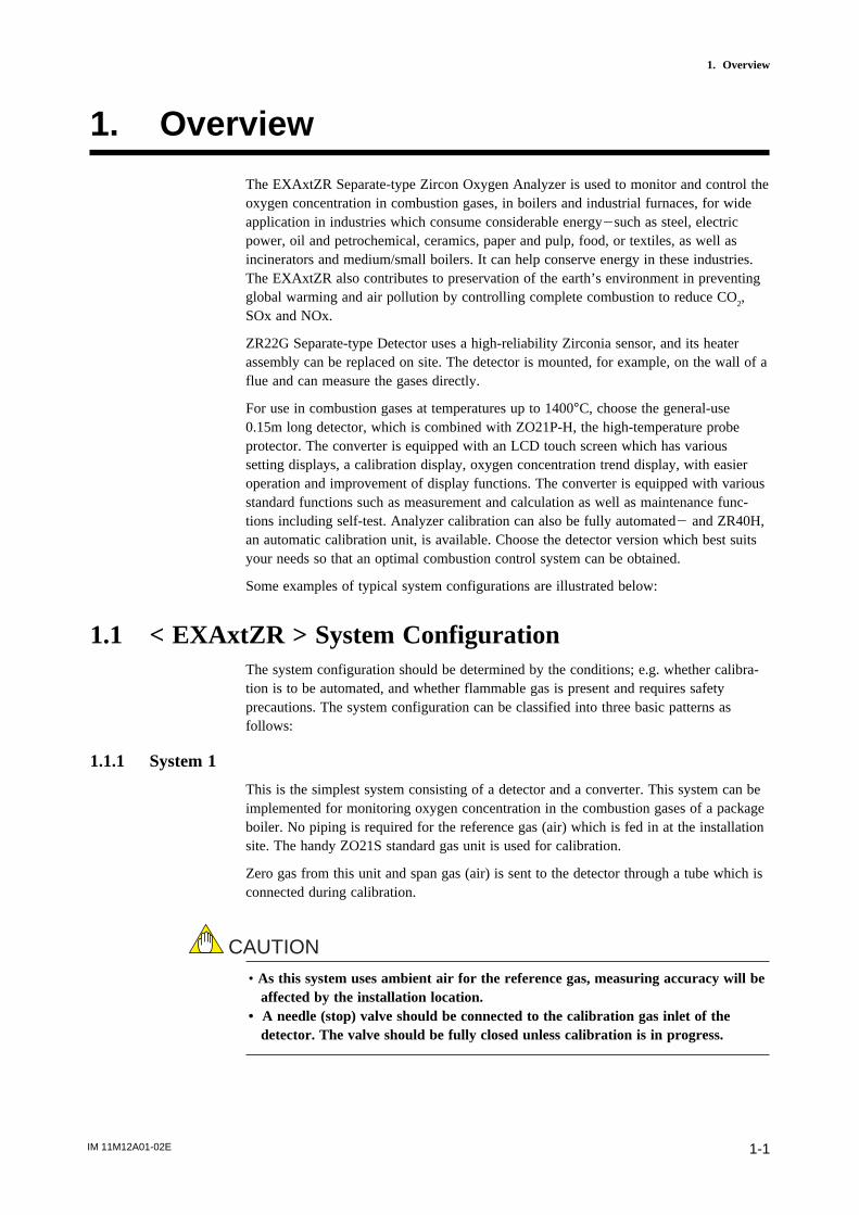
1.1.3 System 3
This example, System 3, represents typical applications in large boilers and heatingfurnaces, where there is a need to monitor and control oxygen concentration. Thereference gas and calibration-time span gas are (clean, dry) instrument air. Zero gas issupplied from a gas cylinder.
System 3 uses the ZR40H autocalibration unit, with auto-switching of the calibrationgas. A “combustible gas detected” contact input turns off power to the heater. There’salso contact output from the converter that can be used to operate a purge gas valve tosupply air to the sensor.
F1.3E.EPS
Model ZR22G Separate type Zirconia OxygenAnalyzerDetector
Model ZR402G Converter
Signal (6-core shield cable)
Heater (2-core)
Reference gas
Calibration gas
Flowmeter Needlevaive
Calibration gasunit case
Zero gas cylinder
100 to 240 V AC
*3
Check valve
Model ZR40H Auto-Calibration unit
Contact inputAnalog output, contact outputDigital output (HART)
Air Set
lnstrument air
Calibration gas pressure regulator
EXA ZR402G
,
*1
*2
*1 Shield cable;
Use shielded signal cables, and connect the shield to the FG terminal of the con-verter.
*2 Select the desired probe from the Probe Configuration table on page 1-4.
*3 When a zirconia oxygen analyzer is used, 100% N2 gas cannot be used as the zero
gas. Use approximately 1% of O2 gas (N2-based).
Figure1.3
IM 11M12A01-02E1-4
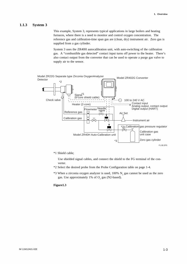
1.2 < EXAxtZR > System Components
1.2.1 System Components
T1.1E.EPS
System Components
Model ZR22G Separate type Zirconia Oxygen Analyzers ,Detector
Model ZR402G Separate type Zirconia Oxygen Analyzer, Converter
Model ZO21P-H Adapter for High temperature Probe of separate type Zirconia Oxygen Analyzer
E7046EC, E7046EN Auxiliary Ejector for High temperature of separate type Oxygen AnalyzerModel ZO21R-L Probe Protector for Zirconia Oxygen Analyzers
K9471UA Filter for Oxygen Analyzer
Model ZO21S Standard Gas Unit
Model ZA8F Flow setting unit for manual calibration
Model ZR40H Automatic Calibration Unit for Separate type Analyzer
L9852CB, G7016XH Stop Valve for Calibration-gas line
K9292DN,K9292DS Check Valve for Calibration-gas line
K9473XH/K9473XJ, G7004XF/K9473XG Air Set
G7001ZC Zero-gas Cylinder
G7013XF, G7014XF Pressure Regulator for Gas Cylinder
E7044KF Case Assembly for Calibration-gas Cylinder
Sparate type
Ex.1 Ex.2 Ex.3
System config.
: Items required for the above system example
: To be selected depending on each application. For details, refer to corresponding chapter.
: Select either
( )
( )
( )
Model ZR22A, ZR202A Heater Assembly (Spare Parts for Model ZR22G)
K9471UC Dust Guard Protector
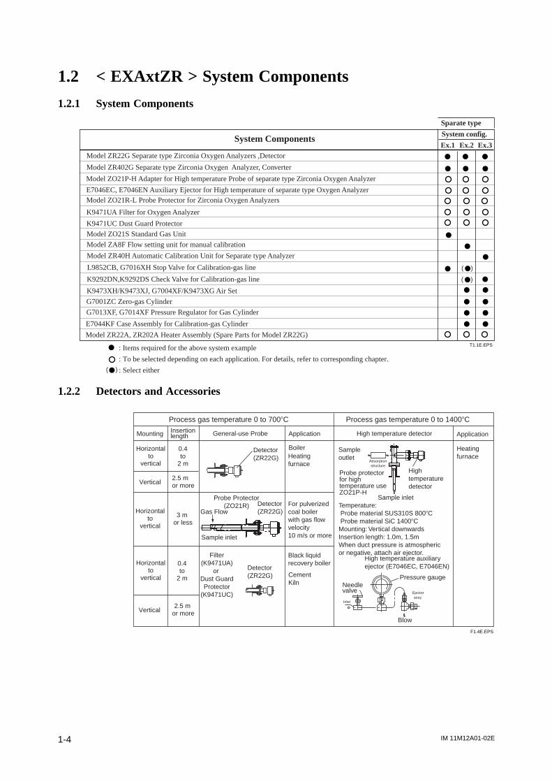
1.2.2 Detectors and Accessories
Detector(ZR22G)
Detector(ZR22G)
Detector (ZR22G)
Probe Protector(ZO21R)
Gas Flow
F1.4E.EPS
Filter(K9471UA)
or Dust GuardProtector
(K9471UC)+
Process gas temperature 0 to 7008C Process gas temperature 0 to 14008C
Mounting Insertionlength General-use Probe High temperature detectorApplication Application
Horizontalto
vertical
Horizontalto
vertical
Horizontalto
vertical
Vertical
Vertical
0.4to
2 m
0.4to
2 m
2.5 mor more
3 m or less
2.5 m or more
BoilerHeating furnace
For pulverizedcoal boilerwith gas flowvelocity10 m/s or more
Black liquidrecovery boiler
CementKiln
Sample inlet
Sampleoutlet
Sample inlet
Hightemperaturedetector
Heatingfurnace
Temperature: Probe material SUS310S 8008C Probe material SiC 14008CMounting: Vertical downwardsInsertion length: 1.0m, 1.5mWhen duct pressure is atmosphericor negative, attach air ejector.
High temperature auxiliaryejector (E7046EC, E7046EN)
Pressure gaugeNeedlevalve
Absorptionstructure
Inlet
Ejectorassy.
Probe protectorfor hightemperature useZO21P-H
Blow
IM 11M12A01-02E 2-1
2. Specifications
2. Specifications
This chapter describes the specifications for the following:
ZR22G General-use separate-type detector (See Section 2.2.1)
ZO21R-L Probe protector (See Section 2.2.2)
ZR22G (0.15 m) High-temperature separate-type detector (See Section 2.3.1)
ZO21P-H Adapter for High temperature probe (See Section 2.3.2)
ZR402G Separate type converter (See Section 2.4)
ZA8F Flow setting unit (See Section 2.5.1)
ZR40H Automatic calibration unit (See Section 2.5.2)
ZO21S Standard gas unit (See Section 2.6)
2.1 General Specifications
2.1.1 Standard Specifications
Measured Object: Oxygen concentration in combustion exhaust gas and mixed gas(excluding inflammable gases, may not be applicable corrosive gas such asammonia is present2check with YOKOGAWA)
The sampling gases containing a corrosive gas such as ammonia or chlorinemay be applicable to our oxygen gas analyzer. In this case, contact withYOKOGAWA and its agency.
Measurement System: Zirconia system
Oxygen concentration: 0.01 to 100 vol% O2
Output Signal: 4 to 20 mA DC (maximum load resistance 550V)
Measurement Range: Any setting in the range of 0 to 5 through 0 to 100 vol% O2 (in
1 vol% O2), or partial range
Digital Communication (HART): 250 to 550V, depending on number of field devicesconnected to the loop (multi-drop mode).
Note: HART is a registered trademark of the HART Communication Foundation.
Display Range: 0 to 100 vol% O2
Warm-up Time: Approx. 20 min.
Repeatability: (Excluding the case where the reference air is by natural convection)
60.5% Maximum value of range setting. (range up to 0 to 25 vol% O2)
61% Maximum value of range setting.
(range from 0 to 25 vol% O2 up to 0 to 100 vol% O
2)
IM 11M12A01-02E2-2
Linearity: (Excluding standard gas tolerance)
(Excluding the case where the reference air flow is natural convection)
(Use oxygen of known concentration (in the measuring range) as the zero and span calibration gas.)
61% Maximun value of range setting ; from 0 to 5 vol% O2 to 0 to 25
vol% O2 range
(Sample gas pressure: within 64.9 kPa)
63% Maximun value of range setting ; from 0 to 25 vol%O2 to 0 to 50 vol%
O2 range
(Sample gas pressure: within 60.49 kPa)
65% Maximum value of range setting ; from 0 to 50 vol% O2 to 0 to 100 vol%
O2 range (Sample gas pressure: within 60.49 kPa)
Drift: (Excluding the first two weeks in use)
(Excluding the case where the reference air flow is natural convection.)
Both zero and span 62% Maximum value of range setting/month
Response Time : Response of 90% within 5 seconds. (Measured from when gas isintroduced from calibration gas inlet and analog output start changing.)
IM 11M12A01-02E 2-3
2. Specifications
2.2 General-use Separate-type Detector and RelatedEquipment
General-use separate-type detector ZR22 can be used in combination with the probeprotector ZO21R-L (see Section 2.2.2).
2.2.1 ZR22G General-use Separate-type Detector
Sample Gas Temperature: 0 to 7008C (Probe only)
It is necessary to mount the cell using Inconel cell-bolts when the temperatureis 6008C or greater.
700 to 14008C (with High Temperature Probe Adapter)
For high-temperature sample gas, apply 0.15 m length probe and High temperature Probe Adapter ZO21P-H.
Sample Gas Pressure: -5 to +250 kPa (When the pressure in the furnace exceeds 3 kPa,it is recommended that you compensate for this pressure. When the pressure inthe furnace exceeds 5 kPa, you must perform pressure compensation.)
For 0.15m probe, 0.5 to 5kPa.
No pressure fluctuation in the furnace should be allowed.
Note: When the detector is used in conjunction with a check valve and a ZA8FFlow Setting Unit, the maximum pressure of sample gas is 150 kPa. When witha check valve and a ZR40H Auto Calibration Unit, it is 200 kPa. If the pressureof your sample gas exceeds these limits, consult with Yokogawa.
Probe Length: 0.15, 0.4, 0.7, 1.0, 1.5, 2.0, 2.5, 3.0, 3.6, 4.2, 4.8, 5.4 m
Probe Material: SUS 316 (JIS)
Ambient Temperature: -20 to +1508C
Reference Air System: Natural Convection, Instrument Air, Pressure Compensation(other than for probe length 0.15 m)
Instrument Air System (excluding Natural Convection) :
Pressure; 200 kPa + the pressure inside the furnace (It is recommended to useair which has been dehumidified by cooling to dew point -208C or less, and haddust or oil mist removed.)
Consumption; Approx. 1 Nl/min
Material in Contact with Gas: SUS 316 (JIS), Zirconia, SUS 304 (JIS) (flange),Hastelloy B, (Inconel 600, 601)
Construction: Heater and thermocouple replaceable construction.
Non explosion-proof JIS C0920 / equivalent to IP44D.
Equivalent to NEMA 4X/IP66 (Achieved when the cable entry is completelysealed with a cable gland in the recirculation pressure compensated version.)
IM 11M12A01-02E2-4
Terminal Box Case: Material; Aluminium alloy
Terminal Box Paint Color:
Case; Mint green (Munsell 5.6BG3.3/2.9)
Cover; Mint green (Munsell 5.6BG3.3/2.9)
Finish: Polyurethane corrosion-resistant coating
Gas Connection: Rc1/4 or 1/4FNPT
Wiring Connection: G1/2, Pg13.5, M20 by 1.5 mm, 1/2 NPT
Installation: Flange mounting
Probe Mounting Angle: Horizontal to vertically downward.
When the probe insertion length is 2 m or less, can install at angles fromhorizontal to vertically downward.
When the probe insertion length is 2.5 or more, mount vertically downward(within 658), and if using a probe protector install at angles between horizontaland vertically downward (within 658).
Weight:Insertion length of 0.4 m: approx. 6 kg (JIS 5K 65) / approx. 11 kg (ANSI 150 4)
Insertion length of 1.0 m: approx. 8 kg (JIS 5K 65)) / approx. 13 kg (ANSI 150 4)
Insertion length of 1.5 m: approx. 10 kg (JIS 5K 65)) / approx. 15 kg (ANSI 150 4)
Insertion length of 2.0 m: approx. 12 kg (JIS 5K 65)) / approx. 17 kg (ANSI 150 4)
Insertion length of 3.0 m: approx. 15 kg (JIS 5K 65)) / approx. 20 kg (ANSI 150 4)
Insertion length of 3.6 m: approx. 17 kg (JIS 5K 65)) / approx. 22 kg (ANSI 150 4)
Insertion length of 4.2 m: approx. 19 kg (JIS 5K 65)) / approx. 24 kg (ANSI 150 4)
Insertion length of 4.8 m: approx. 21 kg (JIS 5K 65)) / approx. 26 kg (ANSI 150 4)
Insertion length of 5.4 m: approx. 23 kg (JIS 5K 65)) / approx. 28 kg (ANSI 150 4)

IM 11M12A01-02E 2-5
2. Specifications
Model
ZR22G
Flange(*3)
-A-B-C-E-F-G-K-L-M-P-Q-R-S-W
Separate type Zirconia Oxygen/ High Temperature Humidity Analyzer, Detector
Length
Wetted material
-015-040-070-100-150-200-250-300-360-420-480-540
-S-C
0.15 m (for high temperature use) (*1)0.4 m0.7 m1.0 m1.5 m2.0 m2.5 m (*2)3.0 m (*2)3.6 m (*2)4.2 m (*2)4.8 m (*2)5.4 m (*2)SUS316Stainless steel with Inconel calibration gas tube (*11)
Suffix code Optioncode Description
T2.1.EPS
Reference air -C-E-P
Gas Thread -R-T
Connection box thread
Instruction manual
-P-G-M-T-Q
-A
-J-E
Options
*1 Used with the ZO21P High Temperature Probe Adapter. Select flange (-Q).*2 When installing horizontally the probe whose insertion length is 2.5 meters or more, use the Probe Protector. Be sure to specify ZO21R-L-200-h. Specify the flange suffix code either -C or -K.*3 The thickness of the flange depends on its dimensions.*4 Not used in conjunction with –P (pressure compensation) for reference air. The flange thickness does not conform to JIS specification.*5 Inconel probe bolts and U shape pipe are used. Use this option for high temperature use (ranging from 600 to 700 8C). *6 Specify either /CV or /SV option code.*7 Not used with the high temperature humidity analyzer.*8 Specify either /SCT or /PT option code.*9 Not waterproof, avoid rain. Operating maximum temperature is 808C. Available only in the U.S.*10 Available only in the U.S. DERAKANE is a registered trademark of the Dow Chemical Company.*11 Recommended if measured gas contains corrosive gas like chlorine.*12 Piping for reference air must be installed to supply reference air constantly at a specified flow rate.
Inconel bolt (*5)/C
DERAKANE coating (*10)/D
Check valve (*6)Stop valve (*6)
/CV/SV
Dust Filter (*7)Dust Guard Protector (*7)
/F1/F2
Stainless steel tag plate (*8)Printed tag plate (*8)
/SCT/PT
ANSI Class 150 2 RF SUS304ANSI Class 150 3 RF SUS304ANSI Class 150 4 RF SUS304DIN PN10 DN50 A SUS304DIN PN10 DN80 A SUS304DIN PN10 DN100 A SUS304JIS 5K 65 FF SUS304JIS 10K 65 FF SUS304JIS 10K 80 FF SUS304JIS 10K 100 FF SUS304JIS 5K 32 FF SUS304 (for high temperature use) (*4)JPI Class 150 4 RF SUS304JPI Class 150 3 RF SUS304WestinghouseNatural convectionExternal connection (Instrument air) (*12)Pressure compensated (*12)
Rc 1/41/4 FNPT
G1/2Pg13.5M20 x1.5 mm1/2NPTQuick connect (*9)
Always -A
JapaneseEnglish
Valves
Filter
Tag plates
Style: S2

IM 11M12A01-02E2-6
EXTERNAL DIMENSIONS
1. Model ZR22G Separate type Zirconia Oxygen Analyzer, Detectors
25
t283 to 292
[50
.8
[12
4
85
L
48
155 to 163 69
[B
[A
C
F2.1E.EPS
L=0.15, 0.4, 0.7, 1.0, 1.5, 2.0, 2.5, 3.03.6, 4.2, 4.8, 5.4 (m)
Rc1/4 or 1/4NPTReference air inlet
2-G1/2,2-1/2NPT etc.Cable connection port
Rc1/4 or 1/4NPTCalibration gas inlet Flange
Flange
Flange
[B
[A
CFlangeANSI Class 150 2 RF SUS304ANSI Class 150 3 RF SUS304ANSI Class 150 4 RF SUS304DIN PN10 DN50 A SUS304DIN PN10 DN80 A SUS304DIN PN10 DN100 A SUS304JIS 5K 65 FF SUS304JIS 10K 65 FF SUS304JIS 10K 80 FF SUS304JIS 10K 100 FF SUS304JIS 5K 32 FF SUS304JPI Class 150 4 RF SUS304JPI Class 150 3 RF SUS304Westinghouse
152.4190.5228.6165200220155175185210115229190155
120.6152.4190.512516018013014015017590
190.5152.4127
4 - [194 - [198 - [194 - [188 - [188 - [184 - [154 - [198 - [198 - [194 - [158 - [194 - [19
4 - [11.5
A B C192424182020141818185242414
t
IM 11M12A01-02E 2-7
2. Specifications
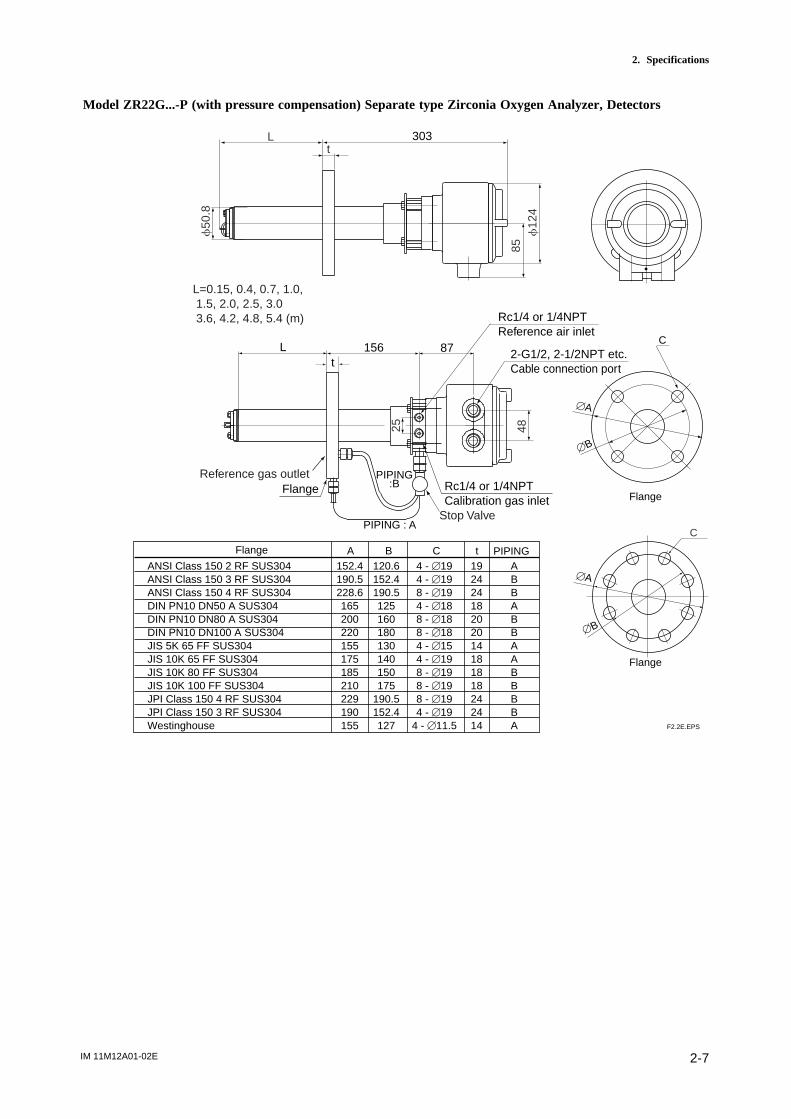
Model ZR22G...-P (with pressure compensation) Separate type Zirconia Oxygen Analyzer, Detectors
F2.2E.EPS
C
PIPINGANSI Class 150 2 RF SUS304ANSI Class 150 3 RF SUS304ANSI Class 150 4 RF SUS304DIN PN10 DN50 A SUS304DIN PN10 DN80 A SUS304DIN PN10 DN100 A SUS304JIS 5K 65 FF SUS304JIS 10K 65 FF SUS304JIS 10K 80 FF SUS304JIS 10K 100 FF SUS304JPI Class 150 4 RF SUS304JPI Class 150 3 RF SUS304Westinghouse
152.4190.5228.6165200220155175185210229190155
120.6152.4190.5125160180130140150175
190.5152.4127
4 - [194 - [198 - [194 - [188 - [188 - [184 - [154 - [198 - [198 - [198 - [194 - [19
4 - [11.5
A B C19242418202014181818242414
ABBABBAABBBBA
t
[B
[A
C
Flange
Flange
[B
[A
Flange
L=0.15, 0.4, 0.7, 1.0, 1.5, 2.0, 2.5, 3.0 3.6, 4.2, 4.8, 5.4 (m)
Rc1/4 or 1/4NPTCalibration gas inlet
25 48
Reference gas outlet
PIPING : A
PIPING:BFlange
Stop Valve
Rc1/4 or 1/4NPTReference air inlet
2-G1/2, 2-1/2NPT etc.Cable connection port
156 87Lt
t303
f50
.8
f12
485
L
IM 11M12A01-02E2-8
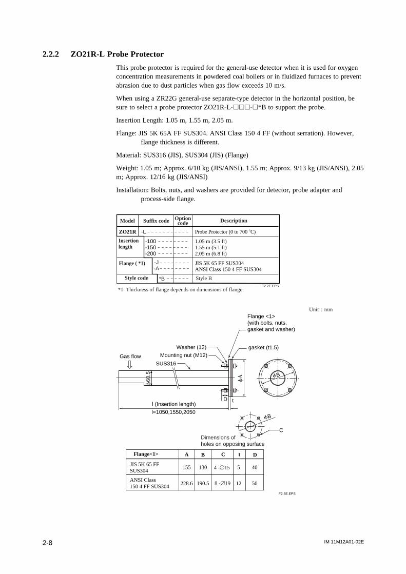
2.2.2 ZO21R-L Probe Protector
This probe protector is required for the general-use detector when it is used for oxygenconcentration measurements in powdered coal boilers or in fluidized furnaces to preventabrasion due to dust particles when gas flow exceeds 10 m/s.
When using a ZR22G general-use separate-type detector in the horizontal position, besure to select a probe protector ZO21R-L-hhh-h*B to support the probe.
Insertion Length: 1.05 m, 1.55 m, 2.05 m.
Flange: JIS 5K 65A FF SUS304. ANSI Class 150 4 FF (without serration). However,flange thickness is different.
Material: SUS316 (JIS), SUS304 (JIS) (Flange)
Weight: 1.05 m; Approx. 6/10 kg (JIS/ANSI), 1.55 m; Approx. 9/13 kg (JIS/ANSI), 2.05m; Approx. 12/16 kg (JIS/ANSI)
Installation: Bolts, nuts, and washers are provided for detector, probe adapter andprocess-side flange.
T2.2E.EPS
ZO21R
JIS 5K 65 FF SUS304ANSI Class 150 4 FF SUS304
-L Probe Protector (0 to 700 8C)
-100-150-200
1.05 m (3.5 ft)1.55 m (5.1 ft)2.05 m (6.8 ft)
Insertionlength
Flange ( *1)
*1 Thickness of flange depends on dimensions of flange.
Model Suffix code Optioncode Description
-J-A
Style code *B Style B
Flange<1>
JIS 5K 65 FFSUS304
155
228.6
130
190.5
5
12
A B C t
ANSI Class150 4 FF SUS304
40
50
D
F2.3E.EPS
D
Flange <1>(with bolts, nuts, gasket and washer)
gasket (t1.5)
SUS316
Dimensions ofholes on opposing surface
fA
Gas flow
Washer (12)
Mounting nut (M12)
l (Insertion length)
l=1050,1550,2050
fB
C
fB
4 -[15
8 -[19
Unit ; mm
t
f60
.5
IM 11M12A01-02E 2-9
2. Specifications
2.3 High-Temperature Separate-type Detector and RelatedEquipment
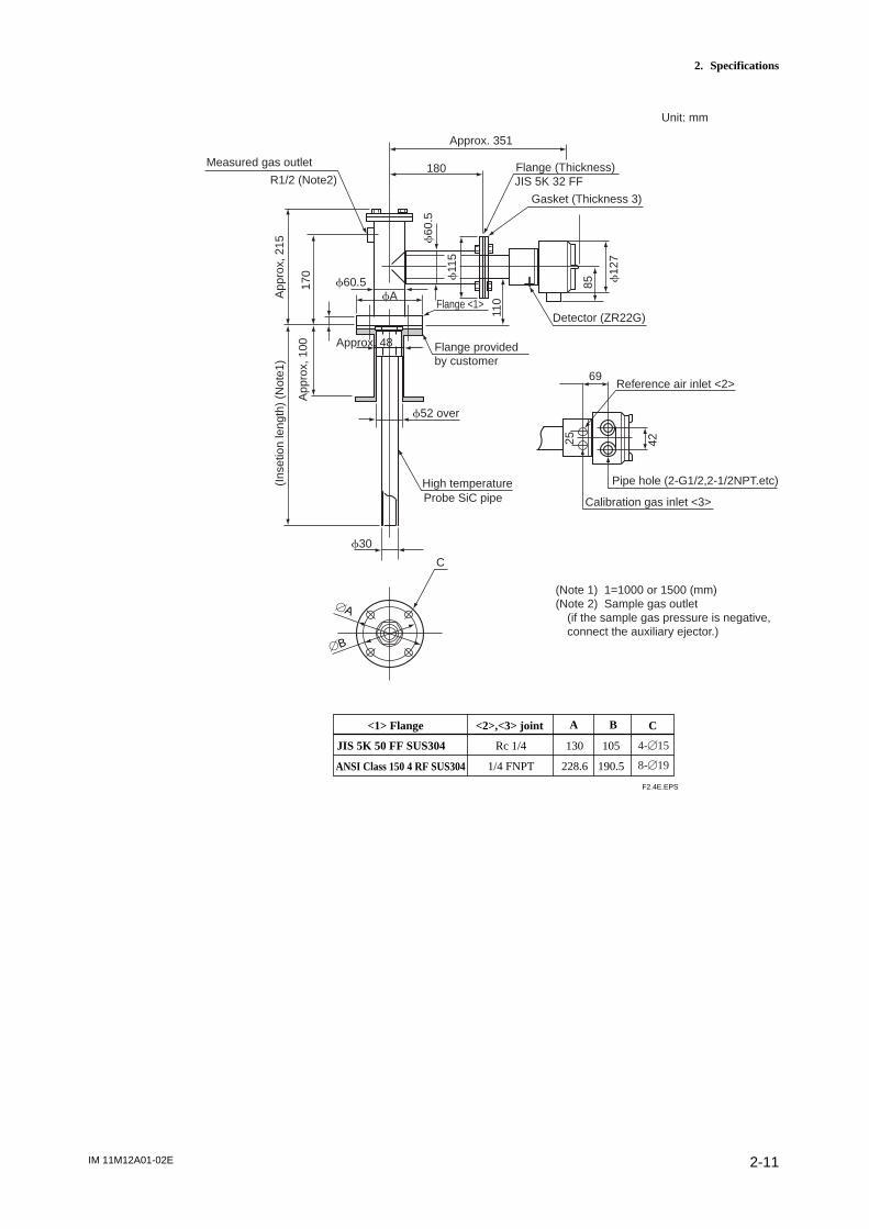
2.3.1 ZR22G (0.15m) High-Temperature Separate-type Detector
Standard Specifications
Construction: Water-resistant, non-explosionproof
Probe length: 0.15 m
Terminal box: Aluminium alloy
Probe material: Probe material in contact with gas: SUS 316 (JIS) (Probe), SUS 304(JIS) (Flange), Zirconia (Sensor), Hastelloy B, (Inconel 600, 601)
Weight: Approx. 3 kg
Installation: Flange mounting (The use of high-temperature detector probe adapter ZO21P-H is necessary.)
Flange standard: JIS 5 K 32 FF equivalent (thickness varies)
Mounting angle: Any angle between horizontal and vertical (high-temperature probe isfitted with an adapter) Reference gas and calibration gas pipingconnection:Rc 1/4 or 1/4 NPT female
Cable inlet: G 1/2, Pg 13.5, M20 3 15, 1/2 NPT
Ambient temperature: -20 to 1508C
Sample gas temperature: 0 to 7008C (temperature at the measuring point of the sam-pling gas. 0 to 7508C or 0 to 14008C when the probe adapter for hightemperature is used.
Temperature of the probe adapter shall not exceed 3008C to protect thegasket and avoid the bolts seizing together.
Sample gas pressure: -0.5 to +5 kPa: when used at the range of more than 0 to25 vol% O2, -0.5 to +0.5 kPa. (An auxiliary ejector is required fornegative pressure application.)
Model and Code
Refer to “Model and Code” in page 2-5.
External Dimensions
Refer to the Figure in page 2-6.

IM 11M12A01-02E2-10
2.3.2 ZO21P-H Adapter for High-Temperature Probe
The probe adapter is used to lower the sample gas to a temperature below 7008C (below3008C at probe adapter surface) before it is fed to the detector.
Insertion length: 1 m, 1.5 m
Material in Contact with Gas:SUS 316 (JIS), Zirconia, SiC or SUS 310S, SUS 304(JIS) (flange)
Probe Material: SiC, SUS 310S (JIS)
Installation: Flange mounting (FF type or RF type)
Probe Mounting Angle: Vertically downward within 658
Where the probe material is SUS 310S, horizontal mounting is available.
Construction: Non explosion-proof. Rainproof construction
Weight: Insertion length of 1.0 m: approx. 6.5 kg (JIS) / approx. 8.5 kg (ANSI)
Insertion length of 1.5 m: approx. 7.5 kg (JIS) / approx. 9.5 kg (ANSI)
Sample gas temperature: 0 to 14008C (when using SiC probe) 0 to 8008C (whenusing SUS 310S probe adapter)
Sample gas pressure: -0.5 to + 5 kPa. When using in the range of 0 to 25 vol% O2 or
more, the sample gas pressure should be in the range of -0.5 to +0.5 kPa.(Where the sample gas pressure for the high-temperature probe is negative, anauxiliary ejector is necessary.)
-100-150
*A
-J-N-M-L-A-R-Q-T-S-E
-H
-A-B
T2.3E.EPS
Model Suffix codeOption
code
ZO21P
Material
InsertionIength
Flange
High Temperature Probe Adapter
SiCSUS 310S
1.0 m1.5 m
JIS 5K 50 FF SUS304JIS 10K 65 FF SUS304JIS 10K 80 FF SUS304JIS 10K 100 FF SUS304ANSI Class 150 4 RF SUS304ANSI Class 150 2 1/2 RF SUS304ANSI Class 150 3 RF SUS304JPI Class 150 3 RF SUS304JPI Class 150 4 RF SUS304DIN PN10 DN50 A SUS304
Style A
Description
Style code
.......................................
.....................................
.....................................
...............................
...............................
.........................................................................................................................................................................................................................................................................................
......................
IM 11M12A01-02E 2-11
2. Specifications
Rc 1/4
1/4 FNPT
F2.4E.EPS
R1/2 (Note2)
Approx. 351
180 Flange (Thickness)JIS 5K 32 FF
Gasket (Thickness 3)
Detector (ZR22G)Flange <1>
f52 over
f30
f60
.5
Reference air inlet <2>
Calibration gas inlet <3>
Pipe hole (2-G1/2,2-1/2NPT.etc)High temperatureProbe SiC pipe
110
f11
5
4225
170
App
rox,
215
(Ins
etio
n le
ngth
) (N
ote1
)
App
rox,
100
69
Approx. 48
C
(Note 1) 1=1000 or 1500 (mm)(Note 2) Sample gas outlet
(if the sample gas pressure is negative, connect the auxiliary ejector.)
f12
7
85
Measured gas outlet
Flange providedby customer
Unit: mm
f60.5fA
[B
[A
<1> Flange
JIS 5K 50 FF SUS304 130
228.6
105
190.5
<2>,<3> joint A B C
ANSI Class 150 4 RF SUS304
4-[15
8-[19
IM 11M12A01-02E2-12
2.4 ZR402G Separate-type Converter
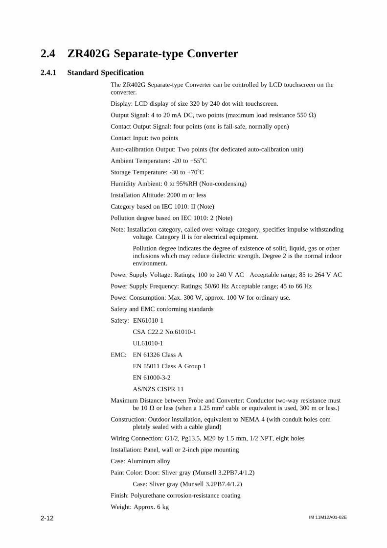
2.4.1 Standard Specification
The ZR402G Separate-type Converter can be controlled by LCD touchscreen on theconverter.
Display: LCD display of size 320 by 240 dot with touchscreen.
Output Signal: 4 to 20 mA DC, two points (maximum load resistance 550 V)
Contact Output Signal: four points (one is fail-safe, normally open)
Contact Input: two points
Auto-calibration Output: Two points (for dedicated auto-calibration unit)
Ambient Temperature: -20 to +558C
Storage Temperature: -30 to +708C
Humidity Ambient: 0 to 95%RH (Non-condensing)
Installation Altitude: 2000 m or less
Category based on IEC 1010: II (Note)
Pollution degree based on IEC 1010: 2 (Note)
Note: Installation category, called over-voltage category, specifies impulse withstandingvoltage. Category II is for electrical equipment.
Pollution degree indicates the degree of existence of solid, liquid, gas or otherinclusions which may reduce dielectric strength. Degree 2 is the normal indoorenvironment.
Power Supply Voltage: Ratings; 100 to 240 V AC Acceptable range; 85 to 264 V AC
Power Supply Frequency: Ratings; 50/60 Hz Acceptable range; 45 to 66 Hz
Power Consumption: Max. 300 W, approx. 100 W for ordinary use.
Safety and EMC conforming standards
Safety: EN61010-1
CSA C22.2 No.61010-1
UL61010-1
EMC: EN 61326 Class A
EN 55011 Class A Group 1
EN 61000-3-2
AS/NZS CISPR 11
Maximum Distance between Probe and Converter: Conductor two-way resistance mustbe 10 V or less (when a 1.25 mm2 cable or equivalent is used, 300 m or less.)
Construction: Outdoor installation, equivalent to NEMA 4 (with conduit holes completely sealed with a cable gland)
Wiring Connection: G1/2, Pg13.5, M20 by 1.5 mm, 1/2 NPT, eight holes
Installation: Panel, wall or 2-inch pipe mounting
Case: Aluminum alloy
Paint Color: Door: Sliver gray (Munsell 3.2PB7.4/1.2)
Case: Sliver gray (Munsell 3.2PB7.4/1.2)
Finish: Polyurethane corrosion-resistance coating
Weight: Approx. 6 kg
IM 11M12A01-02E 2-13
2. Specifications
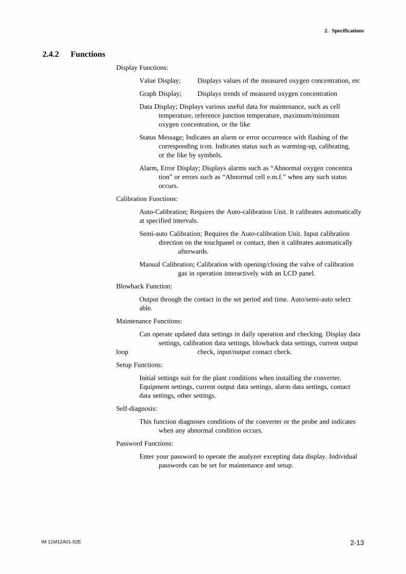
2.4.2 Functions
Display Functions:
Value Display; Displays values of the measured oxygen concentration, etc
Graph Display; Displays trends of measured oxygen concentration
Data Display; Displays various useful data for maintenance, such as celltemperature, reference junction temperature, maximum/minimumoxygen concentration, or the like
Status Message; Indicates an alarm or error occurrence with flashing of thecorresponding icon. Indicates status such as warming-up, calibrating,or the like by symbols.
Alarm, Error Display; Displays alarms such as “Abnormal oxygen concentration” or errors such as “Abnormal cell e.m.f.” when any such statusoccurs.
Calibration Functions:
Auto-Calibration; Requires the Auto-calibration Unit. It calibrates automaticallyat specified intervals.
Semi-auto Calibration; Requires the Auto-calibration Unit. Input calibrationdirection on the touchpanel or contact, then it calibrates automatically
afterwards.
Manual Calibration; Calibration with opening/closing the valve of calibrationgas in operation interactively with an LCD panel.
Blowback Function:
Output through the contact in the set period and time. Auto/semi-auto selectable.
Maintenance Functions:
Can operate updated data settings in daily operation and checking. Display datasettings, calibration data settings, blowback data settings, current output
loop check, input/output contact check.
Setup Functions:
Initial settings suit for the plant conditions when installing the converter.Equipment settings, current output data settings, alarm data settings, contactdata settings, other settings.
Self-diagnosis:
This function diagnoses conditions of the converter or the probe and indicateswhen any abnormal condition occurs.
Password Functions:
Enter your password to operate the analyzer excepting data display. Individualpasswords can be set for maintenance and setup.
IM 11M12A01-02E2-14
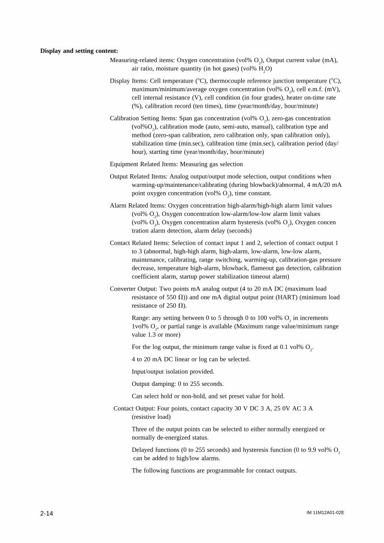
Display and setting content:Measuring-related items: Oxygen concentration (vol% O
2), Output current value (mA),
air ratio, moisture quantity (in hot gases) (vol% H2O)
Display Items: Cell temperature (8C), thermocouple reference junction temperature (8C),maximum/minimum/average oxygen concentration (vol% O
2), cell e.m.f. (mV),
cell internal resistance (V), cell condition (in four grades), heater on-time rate(%), calibration record (ten times), time (year/month/day, hour/minute)
Calibration Setting Items: Span gas concentration (vol% O2), zero-gas concentration
(vol%O2), calibration mode (auto, semi-auto, manual), calibration type and
method (zero-span calibration, zero calibration only, span calibration only),stabilization time (min.sec), calibration time (min.sec), calibration period (day/hour), starting time (year/month/day, hour/minute)
Equipment Related Items: Measuring gas selection
Output Related Items: Analog output/output mode selection, output conditions whenwarming-up/maintenance/calibrating (during blowback)/abnormal, 4 mA/20 mApoint oxygen concentration (vol% O
2), time constant.
Alarm Related Items: Oxygen concentration high-alarm/high-high alarm limit values(vol% O
2), Oxygen concentration low-alarm/low-low alarm limit values
(vol% O2), Oxygen concentration alarm hysteresis (vol% O
2), Oxygen concen
tration alarm detection, alarm delay (seconds)
Contact Related Items: Selection of contact input 1 and 2, selection of contact output 1to 3 (abnormal, high-high alarm, high-alarm, low-alarm, low-low alarm,maintenance, calibrating, range switching, warming-up, calibration-gas pressuredecrease, temperature high-alarm, blowback, flameout gas detection, calibrationcoefficient alarm, startup power stabilization timeout alarm)
Converter Output: Two points mA analog output (4 to 20 mA DC (maximum loadresistance of 550 V)) and one mA digital output point (HART) (minimum loadresistance of 250 V).
Range: any setting between 0 to 5 through 0 to 100 vol% O2 in increments
1vol% O2, or partial range is available (Maximum range value/minimum range
value 1.3 or more)
For the log output, the minimum range value is fixed at 0.1 vol% O2.
4 to 20 mA DC linear or log can be selected.
Input/output isolation provided.
Output damping: 0 to 255 seconds.
Can select hold or non-hold, and set preset value for hold.
Contact Output: Four points, contact capacity 30 V DC 3 A, 25 0V AC 3 A(resistive load)
Three of the output points can be selected to either normally energized ornormally de-energized status.
Delayed functions (0 to 255 seconds) and hysteresis function (0 to 9.9 vol% O2
can be added to high/low alarms.
The following functions are programmable for contact outputs.
IM 11M12A01-02E 2-15
2. Specifications
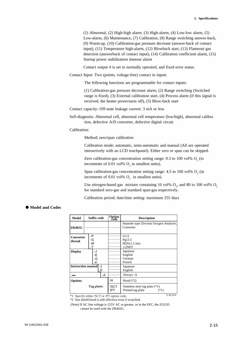
(1) Abnormal, (2) High-high alarm, (3) High-alarm, (4) Low-low alarm, (5)Low-alarm, (6) Maintenance, (7) Calibration, (8) Range switching answer-back,(9) Warm-up, (10) Calibration-gas pressure decrease (answer-back of contactinput), (11) Temperature high-alarm, (12) Blowback start, (13) Flameout gasdetection (answerback of contact input), (14) Calibration coefficient alarm, (15)Startup power stabilization timeout alarm
Contact output 4 is set to normally operated, and fixed error status.
Contact Input: Two (points, voltage-free) contact in inputs
The following functions are programmable for contact inputs:
(1) Calibration-gas pressure decrease alarm, (2) Range switching (Switchedrange is fixed), (3) External calibration start, (4) Process alarm (if this signal isreceived, the heater powerturns off), (5) Blow-back start
Contact capacity: Off-state leakage current: 3 mA or less
Self-diagnosis: Abnormal cell, abnormal cell temperature (low/high), abnormal calibration, defective A/D converter, defective digital circuit
Calibration:
Method; zero/span calibration
Calibration mode; automatic, semi-automatic and manual (All are operatedinteractively with an LCD touchpanel). Either zero or span can be skipped.
Zero calibration-gas concentration setting range: 0.3 to 100 vol% O2 (in
increments of 0.01 vol% O2 in smallest units).
Span calibration-gas concentration setting range: 4.5 to 100 vol% O2 (in
increments of 0.01 vol% O2 in smallest units).
Use nitrogen-based gas mixture containing 10 vol% O2, and 80 to 100 vol% O
2
for standard zero-gas and standard span-gas respectively.
Calibration period; date/time setting: maximum 255 days
d Model and Codes
ZR402G
Converterthread
-P-G-M-T
G1/2Pg13.5M20x1.5 mm1/2NPT
T2.4E.EPS
Separate type Zirconia Oxygen Analyzer, Converter
Model Suffix code Optioncode Description
Tag plates
*1 Specify either /SCT or /PT option code.*2 Sun shield hood is still effective even if scratched.
-J-E-G-F
Display
-A
-J-E
/H
Instruction manual
Options
/SCT/PT
Hood (*2)
JapaneseEnglish
JapaneseEnglishGermanFrench
Always -A
Stainless steel tag plate (*1)Printed tag plate (*1)
(Note) If AC line voltage is 125V AC or greater, or in the EEC, the ZO21D cannot be used with the ZR402G.
IM 11M12A01-02E2-16
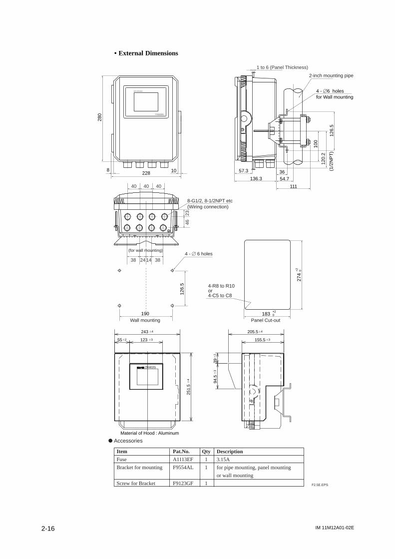
• External Dimensions
F2.5E.EPS
d Accessories
Item
Fuse
Bracket for mounting
Screw for Bracket
Pat.No.
A1113EF
F9554AL
F9123GF
Qty
1
1
1
Description
3.15A
for pipe mounting, panel mounting
or wall mounting
ZR402G
64243
64
251.
5
63155.5
64205.5
631236255
62
396
394
.5
Material of Hood : Aluminum
1 to 6 (Panel Thickness)
EXA ZR402G 4 - [6 holesfor Wall mounting
4-R8 to R10or4-C5 to C8
4 - [ 6 holes
2-inch mounting pipe
Wall mounting Panel Cut-out10
0
108228
280
126.
5
57.3
136.3 54.7
111
36
120.
2
(1/2
NP
T)
190 183+20
274
+2
0
126.
540
38 24 14 38
40 4023
46
8-G1/2, 8-1/2NPT etc(Wiring connection)
(for wall mounting)
IM 11M12A01-02E 2-17
2. Specifications
2.5 ZA8F Flow Setting Unit and ZR40H Automatic Cali-bration Unit
2.5.1 ZA8F Flow Setting Unit
This flow setting unit is applied to the reference gas and the calibration gas in a systemconfiguration (System 2).
This unit consists of a flow meter and flow control valves to control the flow of calibra-tion gas and reference air.
Standard Specifications
FIowmeter: Calibration gas; 0.1 to 1.0 l/min. Reference air; 0.1 to 1.0 l/min.
Construction: Dust-proof and rainproof construction
Case Material: SPCC (Cold rolled steel sheet)
Painting: Baked epoxy resin, Dark-green (Munsell 2.0 GY 3.1/0.5 or equivalent)
Pipe Connections: Rc1/4 or 1/4FNPT
Reference Air pressure: Clean air supply of measured gas pressure1approx. 50 kPa G
(or measured gas pressure plus approx. 150 kPa G when a cheack valve is used)
pressure at inlet of the auto-calibration unit.(Maximun 300 kPaG)
Air Consumption: Approx. 1.5 l/min
Weight: Approx. 2.3kg
Calibration gas (zero gas, span gas) flow 0.7 l/m (at calibration time only)
Note
Use instrument air for span calibration gas, if no instrument air is available, contactYOKOGAWA.
ZA8F
-J-A
T2.5E.EPS
Model Suffix code Option code Description
Flow setting unit
JointWith 1/4" NPT adapter
Style B
Rc 1/4
Style code *B
IM 11M12A01-02E2-18
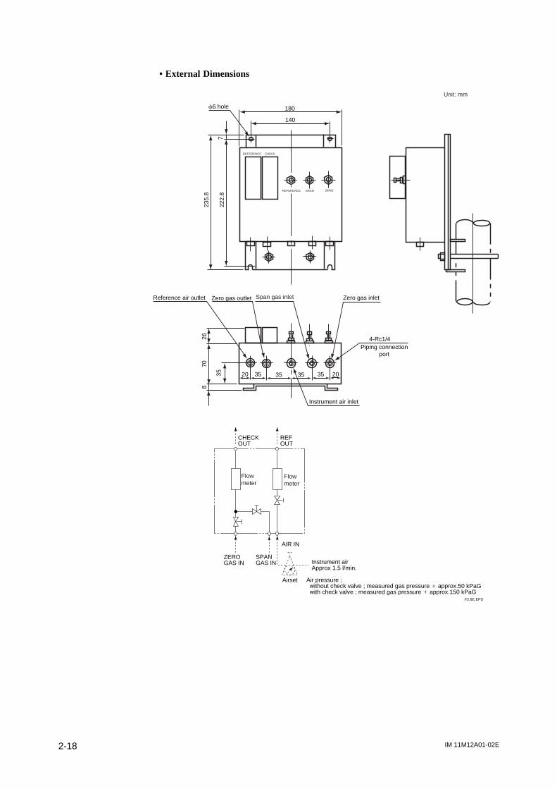
• External Dimensions
f6 hole
Reference air outlet Zero gas outlet Zero gas inlet
Instrument air inlet
4-Rc1/4
20 2035 35
Piping connectionport
180
235.
870
35
268
222.
8
140
F2.6E.EPS
REFERENCE CHECK
REFERENCE SRAN ZERO
CHECKOUT
ZERO GAS IN
AIR IN
Instrument airApprox 1.5 l/min.
Air pressure ; without check valve ; measured gas pressure 1 approx.50 kPaG with check valve ; measured gas pressure 1 approx.150 kPaG
REFOUT
Flowmeter
Flowmeter
Airset
Unit: mm
35 35
Span gas inlet
SPAN GAS IN
7
IM 11M12A01-02E 2-19
2. Specifications
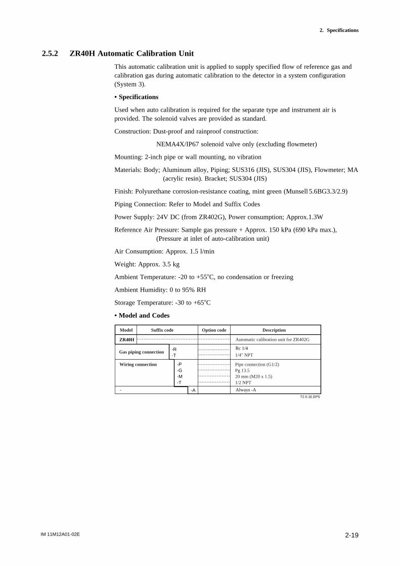
2.5.2 ZR40H Automatic Calibration Unit
This automatic calibration unit is applied to supply specified flow of reference gas andcalibration gas during automatic calibration to the detector in a system configuration(System 3).
• Specifications
Used when auto calibration is required for the separate type and instrument air isprovided. The solenoid valves are provided as standard.
Construction: Dust-proof and rainproof construction:
NEMA4X/IP67 solenoid valve only (excluding flowmeter)
Mounting: 2-inch pipe or wall mounting, no vibration
Materials: Body; Aluminum alloy, Piping; SUS316 (JIS), SUS304 (JIS), Flowmeter; MA(acrylic resin). Bracket; SUS304 (JIS)
Finish: Polyurethane corrosion-resistance coating, mint green (Munsell 5.6BG3.3/2.9)
Piping Connection: Refer to Model and Suffix Codes
Power Supply: 24V DC (from ZR402G), Power consumption; Approx.1.3W
Reference Air Pressure: Sample gas pressure + Approx. 150 kPa (690 kPa max.),(Pressure at inlet of auto-calibration unit)
Air Consumption: Approx. 1.5 l/min
Weight: Approx. 3.5 kg
Ambient Temperature: -20 to +558C, no condensation or freezing
Ambient Humidity: 0 to 95% RH
Storage Temperature: -30 to +658C
• Model and Codes
ZR40H
-R-T
T2.5-1E.EPS
Model Suffix code Option code Description
Automatic calibration unit for ZR402G
Gas piping connection1/4" NPT
Pipe connection (G1/2)Pg 13.520 mm (M20 x 1.5)1/2 NPT
Rc 1/4
Wiring connection -P-G-M-T
-A Always -A-

IM 11M12A01-02E2-20
• External Dimensions
OCK
140
250
42
26
41.2 41.2
54 71.526
49.5
1222
3
4616
3040 47.5 25
102
MA
X58
90 116.5
f 6.5
*1 with four M6 screws can wall-mount
*1 4-
(wiring inlet is at same position on rear)
Flowmeter
Setting Valve forcalibration gas
Setting Valve forreference air
wiring inlet ; 2-G1/2,Pg13.5,M2031.5 or 1/2NPT(Female)
calibration gas outlet Rc1/4 or 1/4 NPT(Female)
Zero gas inlet Rc1/4 or 1/4 NPT(Female)
reference air inlet Rc1/4 or 1/4 NPT(Female)Rc1/4 or 1/4 NPT(Female)
reference air outlet
2B pipe mounting example
F2.6-2E.EPS
Unit : mm
IM 11M12A01-02E 2-21
2. Specifications
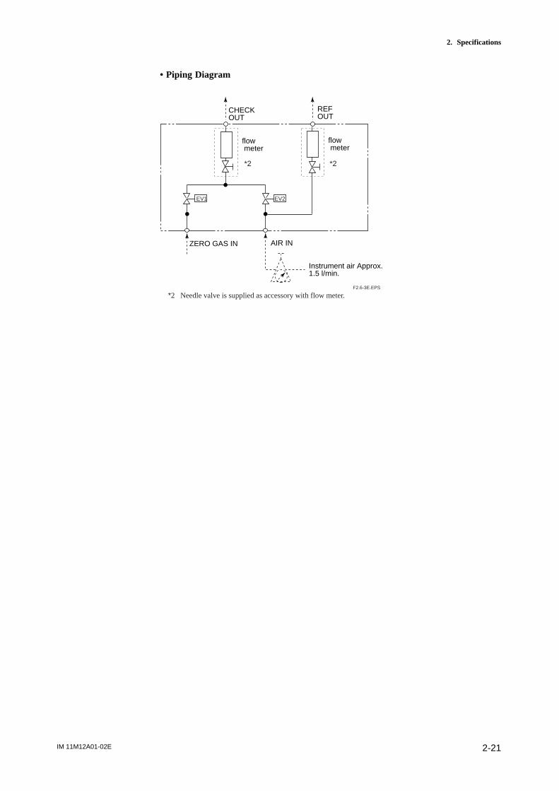
• Piping Diagram
CHECKOUT
ZERO GAS IN AIR IN
Instrument air Approx.1.5 l/min.
flow meter
flow meter
REFOUT
*2 *2
EV1 EV2
*2 Needle valve is supplied as accessory with flow meter.F2.6-3E.EPS
IM 11M12A01-02E2-22
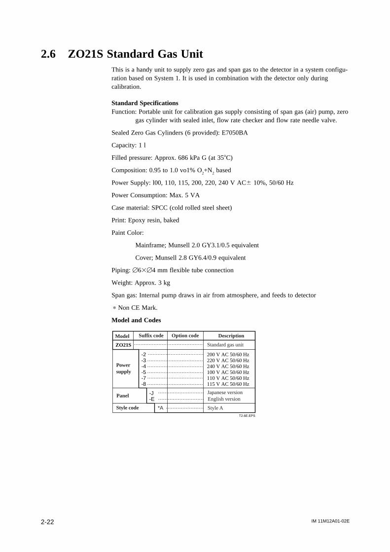
2.6 ZO21S Standard Gas UnitThis is a handy unit to supply zero gas and span gas to the detector in a system configu-ration based on System 1. It is used in combination with the detector only duringcalibration.
Standard SpecificationsFunction: Portable unit for calibration gas supply consisting of span gas (air) pump, zero
gas cylinder with sealed inlet, flow rate checker and flow rate needle valve.
Sealed Zero Gas Cylinders (6 provided): E7050BA
Capacity: 1 l
Filled pressure: Approx. 686 kPa G (at 358C)
Composition: 0.95 to 1.0 vo1% O2+N
2 based
Power Supply: l00, 110, 115, 200, 220, 240 V AC6 10%, 50/60 Hz
Power Consumption: Max. 5 VA
Case material: SPCC (cold rolled steel sheet)
Print: Epoxy resin, baked
Paint Color:
Mainframe; Munsell 2.0 GY3.1/0.5 equivalent
Cover; Munsell 2.8 GY6.4/0.9 equivalent
Piping: [63[4 mm flexible tube connection
Weight: Approx. 3 kg
Span gas: Internal pump draws in air from atmosphere, and feeds to detector
p Non CE Mark.
Model and Codes
ZO21S
-2-3-4-5-7-8
-J-E
200 V AC 50/60 Hz220 V AC 50/60 Hz240 V AC 50/60 Hz100 V AC 50/60 Hz110 V AC 50/60 Hz115 V AC 50/60 Hz
T2.6E.EPS
Model Suffix code Option code Description
Standard gas unit
Power supply
Panel
Style code *A
Japanese versionEnglish version
Style A
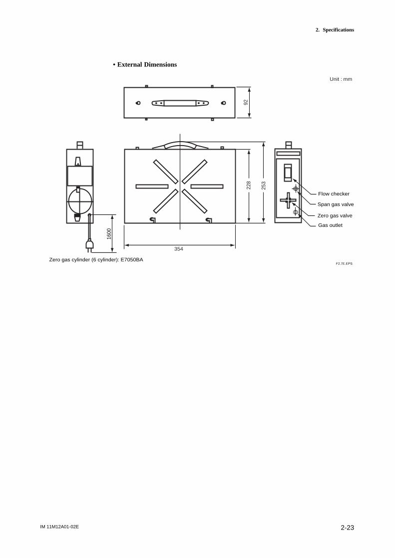
IM 11M12A01-02E 2-23
2. Specifications
• External Dimensions
228
253
35492
1600
Flow checker
Span gas valve
Zero gas valve
Gas outlet
F2.7E.EPSZero gas cylinder (6 cylinder): E7050BA
Unit : mm
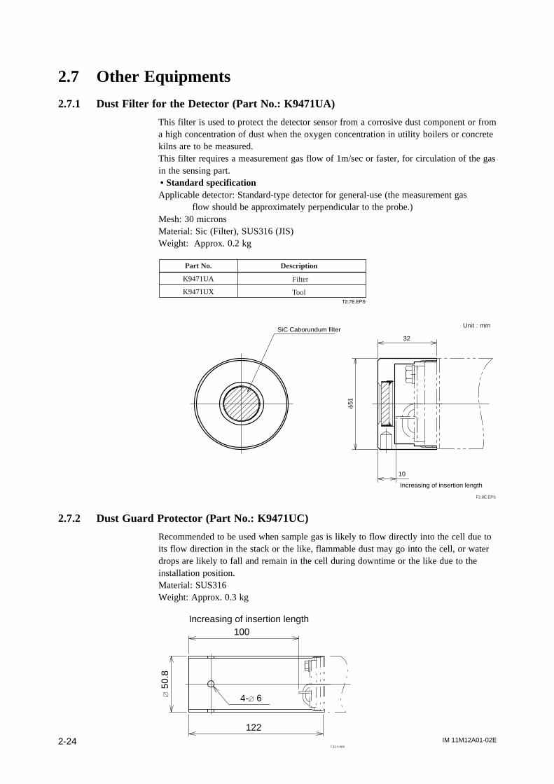
IM 11M12A01-02E2-24
2.7 Other Equipments
2.7.1 Dust Filter for the Detector (Part No.: K9471UA)
This filter is used to protect the detector sensor from a corrosive dust component or froma high concentration of dust when the oxygen concentration in utility boilers or concretekilns are to be measured.This filter requires a measurement gas flow of 1m/sec or faster, for circulation of the gasin the sensing part.• Standard specificationApplicable detector: Standard-type detector for general-use (the measurement gas
flow should be approximately perpendicular to the probe.)Mesh: 30 micronsMaterial: Sic (Filter), SUS316 (JIS)Weight: Approx. 0.2 kg
T2.7E.EPS
Part No.
K9471UA
K9471UX
Description
Filter
Tool
f51
32
10
SiC Caborundum filter
Increasing of insertion length
F2.8E.EPS
Unit : mm
2.7.2 Dust Guard Protector (Part No.: K9471UC)
Recommended to be used when sample gas is likely to flow directly into the cell due toits flow direction in the stack or the like, flammable dust may go into the cell, or waterdrops are likely to fall and remain in the cell during downtime or the like due to theinstallation position.Material: SUS316Weight: Approx. 0.3 kg
4-[ 6
122
[50
.8
100Increasing of insertion length
F11-1.eps
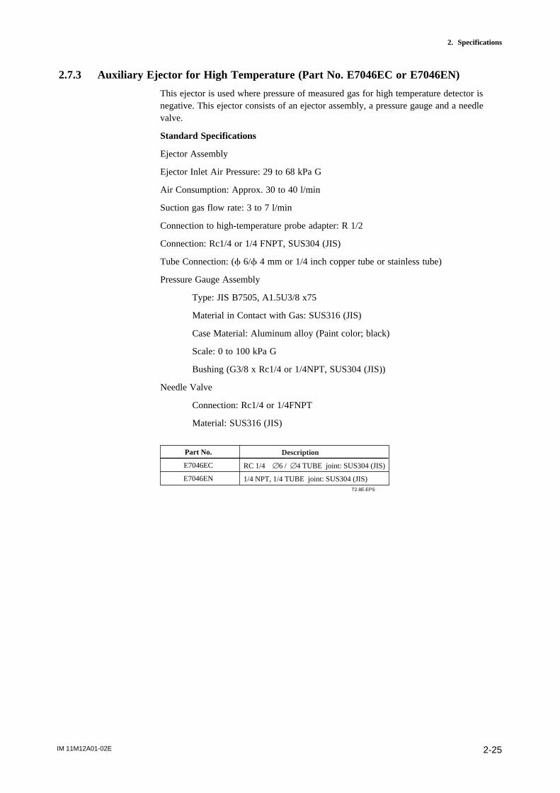
IM 11M12A01-02E 2-25
2. Specifications
2.7.3 Auxiliary Ejector for High Temperature (Part No. E7046EC or E7046EN)
This ejector is used where pressure of measured gas for high temperature detector isnegative. This ejector consists of an ejector assembly, a pressure gauge and a needlevalve.
Standard Specifications
Ejector Assembly
Ejector Inlet Air Pressure: 29 to 68 kPa G
Air Consumption: Approx. 30 to 40 l/min
Suction gas flow rate: 3 to 7 l/min
Connection to high-temperature probe adapter: R 1/2
Connection: Rc1/4 or 1/4 FNPT, SUS304 (JIS)
Tube Connection: (f 6/f 4 mm or 1/4 inch copper tube or stainless tube)
Pressure Gauge Assembly
Type: JIS B7505, A1.5U3/8 x75
Material in Contact with Gas: SUS316 (JIS)
Case Material: Aluminum alloy (Paint color; black)
Scale: 0 to 100 kPa G
Bushing (G3/8 x Rc1/4 or 1/4NPT, SUS304 (JIS))
Needle Valve
Connection: Rc1/4 or 1/4FNPT
Material: SUS316 (JIS)
RC 1/4 [6 / [4 TUBE joint: SUS304 (JIS)
1/4 NPT, 1/4 TUBE joint: SUS304 (JIS)T2.8E.EPS
Part No.
E7046EC
E7046EN
Description

IM 11M12A01-02E2-26
38
Approx.88
40 20
Qa
L
200
100
0 5 10 15
P= 0.5
0
40
30
40 60 80
Po (kPa) Qa (l/min)
0
-1.0
-0.5
40 60 80
Pg (kPa)
0
8
4
40 60 80
Qg (l/min)
L (m) P (kPa)
P (kPa) P (kPa)
Po (kPa) : Pressure settingP (kPa) : Drive pressure (at the ejector entrance) Pg (kPa) : Suction pressureQa (l/min) : Air consumptionQg (l/min) : Suction flowL (m) : Distance between the ejector and the pressure gauge
Needle valve
Pressure gauge
39
lnstrumentair inlet
f43
Height whenfully openApprox.67
Not included in hightemperature useauxiliary ejector.
f63f4 or 1/4 inch, conduit (stainless)
Ejector assembly
PT 1/2 maleApprox.70
Auxiliary ejector forhigh-temperature mounting place use.
Detector
Needlevalve Pressure gauge
Ejector
Po
Airsource
Gas
Pg
Qg
Gas pressure : -15 Pa
Air consumption characteristicsPressure setting characteristics
Suction pressure characteristics Suction flow characteristics
F2.9E.EPS
Gas Pressure:0 kPa
1) 2)
3) 4)
E7046EC ; Piping connections, Rc1/4( p part) or Rc1/4( pp part ),E7046EN ; Piping connections,1/4NPT female ( p part) or 1/4NTP male( pp part )
p p
p
pp
(Note) Pipes and connectors are not provided.

IM 11M12A01-02E 2-27
2. Specifications
< Pressure setting for the auxiliary ejector for high-temperature use >Pressure supply for the auxiliary ejector should be set so that the suction flow of themeasured gas becomes approximately 5 l/min.
To set this, proceed as follows:
(1) In Graph 4, draw a horizontal line from the 5 l/min point. on the vertical axis(Suction flow: Qg) toward the gas pressure line to be used, to find the point ofintersection.Draw a line vertically down from the point of intersection to the axis to find thedrive pressure, P (at the ejector entrance).
(2) In Graph 1, determine Po (pressure setting) from L (the distance between the ejectorand the pressure gauge).
(3) Open the needle valve to supply air for the ejector to the pressure gauge until itindicates the pressure setting, Po.
Note
Qg (the suction flow) may require change according to the conditions of use. Refer toSection 3.2.2 and Section 4.1.4 for details.
Graph explanation1) Graph 1 is to compensate for pressure loss in piping between the ejector and the
pressure gauge, and find Po (pressure setting).2) Graph 2 shows correlation between P (drive pressure) and Qa (air consumption).3) Graph 3 shows correlation between P (drive pressure) and Pg (suction pressure; when
the measured gas inlet of the ejector is closed).4) Graph 4 shows correlation between P (drive pressure) and Qg (suction flow) for each
gas pressure.
2.7.4 Stop Valve (Part No. L9852CB or G7016XH)
This valve mounted on the calibration gas line in the system to allow for one-touchcalibration. This is applies to the system configuration shown for system 1 insection 1.
Standard SpecificationsConnection: Rc 1/4 or 1/4 FNPT
Material: SUS 316 (JIS)
Weight: Approx. 80 g
Joint: RC 1/4, Material: SUS 316 (JIS)
Joint: 1/4 NPT, Material: SUS316 (JIS)T2.9E.EPS
DescriptionPart No.
L9852CB
G7016XH
F15.EPS
(Ful
l ope
n le
ngth
)
40
Rc1/4 or 1/4NPT
43
55
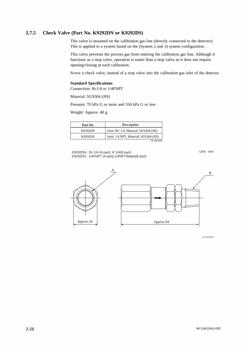
IM 11M12A01-02E2-28
2.7.5 Check Valve (Part No. K9292DN or K9292DS)
This valve is mounted on the calibration gas line (directly connected to the detector).This is applied to a system based on the (System 2 and 3) system configuration .
This valve prevents the process gas from entering the calibration gas line. Although itfunctions as a stop valve, operation is easier than a stop valve as it does not requireopening/closing at each calibration.
Screw a check valve, instead of a stop valve into the calibration gas inlet of the detector.
Standard SpecificationsConnection: Rc1/4 or 1/4FNPT
Material: SUS304 (JIS)
Pressure: 70 kPa G or more and 350 kPa G or less
Weight: Approx. 40 g
Joint: RC 1/4, Material: SUS304 (JIS)
Joint: 1/4 NPT, Material: SUS304 (JIS)T2.10E.EPS
Part No.
K9292DN
K9292DS
Description
K9292DN : Rc 1/4 (A part), R 1/4(B part)K9292DS : 1/4FNPT (A part),1/4NPT(Male)(B part)
F2.11E.EPS
Approx.19 Approx.54
AB
Unit : mm

IM 11M12A01-02E 2-29
2. Specifications
2.7.6 Air Set
This set is used to lower the pressure when instrument air is used as the reference andspan gases.
• Part No. K9473XH or K9473XJ
Standard SpecificationsPrimary Pressure: Max. 2 MPa G
Secondary Pressure: 0 to 0.25 MPa G
Connection: Rc1/4 or 1/4FNPT (includes joint adapter)
Weight: Approx.1 kg
Joint: Rc 1/4, Material: Aluminum
Joint: 1/4 NPT (F) , Material: Body; Aluminum, Adapter; Zinc alloy
T2.11E.EPS
Part No.
K9473XH
K9473XJ
Description
(116)
(53.
5)
842
28 18.5
7
40
Bracket Mounting Dimensions
[54
(63)
K9473XH: Piping connection (IN: Primary side, OUT: Secondary side), Rc1/4 K9473XJ: Piping connection (IN: Primary side, OUT: Secondary side), 1/4NPT
Unit: mmDimensions in parentheses are approximate.
69.5
[48(1
35.5
)(4
3.5)
60
IN OUT
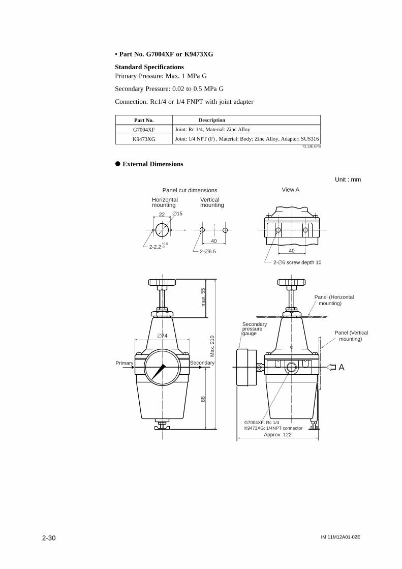
IM 11M12A01-02E2-30
• Part No. G7004XF or K9473XG
Standard SpecificationsPrimary Pressure: Max. 1 MPa G
Secondary Pressure: 0.02 to 0.5 MPa G
Connection: Rc1/4 or 1/4 FNPT with joint adapter
Joint: Rc 1/4, Material: Zinc Alloy
Joint: 1/4 NPT (F) , Material: Body; Zinc Alloy, Adapter; SUS316T2.13E.EPS
Part No.
G7004XF
K9473XG
Description
d External Dimensions
A
22 [15
2-2.2+0.5-0
2-[6.5
40
2-[6 screw depth 10
40
[74
Primary Secondary
88
Max
. 210
max
. 55
Approx. 122
Secondarypressuregauge
Panel (Horizontal mounting)
Panel (Vertical mounting)
G7004XF: Rc 1/4K9473XG: 1/4NPT connector
Horizontal mounting
Vertical mounting
Panel cut dimensions View A
Unit : mm
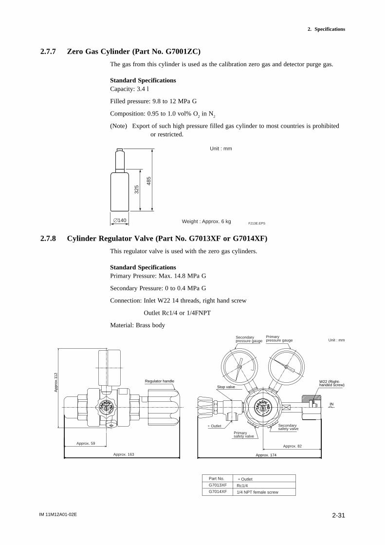
IM 11M12A01-02E 2-31
2. Specifications
2.7.7 Zero Gas Cylinder (Part No. G7001ZC)
The gas from this cylinder is used as the calibration zero gas and detector purge gas.
Standard SpecificationsCapacity: 3.4 l
Filled pressure: 9.8 to 12 MPa G
Composition: 0.95 to 1.0 vol% O2 in N
2
(Note) Export of such high pressure filled gas cylinder to most countries is prohibitedor restricted.
485
325
[140
Unit : mm
F213E.EPSWeight : Approx. 6 kg
2.7.8 Cylinder Regulator Valve (Part No. G7013XF or G7014XF)
This regulator valve is used with the zero gas cylinders.
Standard SpecificationsPrimary Pressure: Max. 14.8 MPa G
Secondary Pressure: 0 to 0.4 MPa G
Connection: Inlet W22 14 threads, right hand screw
Outlet Rc1/4 or 1/4FNPT
Material: Brass body
´J
HI HO
CAKA
T
Regulator handle W22 (Right-handed screw)Stop valve
Approx. 174
App
rox.
112
INHI HAC
AKT
´ J
O
Outletp
Part No.
G7013XF
G7014XF
p Outlet
Rc1/4
1/4 NPT female screw
Secondarypressure gauge
Primarypressure gauge
Secondary safety valve
Primary safety valve
Approx. 82Approx. 59
Approx. 163
Unit : mm
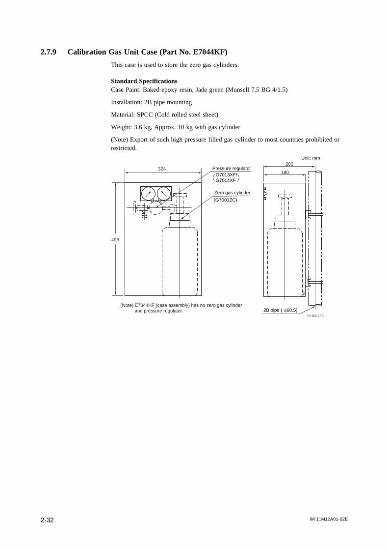
IM 11M12A01-02E2-32
2.7.9 Calibration Gas Unit Case (Part No. E7044KF)
This case is used to store the zero gas cylinders.
Standard SpecificationsCase Paint: Baked epoxy resin, Jade green (Munsell 7.5 BG 4/1.5)
Installation: 2B pipe mounting
Material: SPCC (Cold rolled steel sheet)
Weight: 3.6 kg, Approx. 10 kg with gas cylinder
(Note) Export of such high pressure filled gas cylinder to most countries prohibited orrestricted.
324
496
200
180Pressure regulator
Zero gas cylinder
2B pipe ( f60.5)
(G7001ZC)
G7013XF/G7014XF
F2.15E.EPS
(Note) E7044KF (case assembly) has no zero gas cylinder and pressure regulator.
Unit: mm

IM 11M12A01-02E 2-33
2. Specifications
2.7.10 Model ZR22A Heater Assembly
ZR22A
-015-040-070-100-150-200-250-300
T23.EPS
Model Suffix code Description
Length(p1)
Jig for change -A-N
Reference air (*3)
Style: S2
-A
-B-C
Reference air Natural convention
External connection (Instrument air)
Pressure compensated (for ZR22G S2)
Pressure compensated (for ZR22G S1)
p1 Suffix code of length should be selected as same as ZR22G installed.
p2 Jig part no. is K9470BX to order as a parts after purchase.
p3 Select appropriately among "-A", "-B", "-C" according to the reference air supply method and style.
(Note) The heater is made of ceramic, do not drop or subject it to pressure stress.
Option code
Heater Assembly for ZR22G
0.15 m0.4 m0.7 m1 m1.5 m2 m2.5 m3 m
with Jig (*2)None
d External Dimensions
K94
70B
X
L Weight (kg)
ZR22A-015
ZR22A-040
ZR22A-070
ZR22A-100
ZR22A-150
ZR22A-200
ZR22A-250
ZR22A-300
302
552
852
1152
1652
2152
2652
3152
Approx. 0.5
Approx. 0.8
Approx. 1.2
Approx. 1.6
Approx. 2.2
Approx. 2.8
Approx. 3.4
Approx. 4.0
Jig for change
L612
(K9470BX) [ 2
1.7
30
Unit : mm
[ 4
5
L length
Model & Code
F2.16E.EPS

IM 11M12A01-02E 3-1
3. Installation
3. Installation
This chapter describes installation of the following equipment:
Ssction 3.1 Detector (except model ZR22G-015)
Ssction 3.2 Detector (model ZR22G-015)
Ssction 3.3 Converter
Ssction 3.4 ZA8F Flow Setting Unit
Ssction 3.5 ZR40H Automatic Calibration Unit
Ssction 3.6 Calibration Gas Unit Case (E7044KF)
3.1 Installation of the Detector
3.1.1 Location
The following should be taken into consideration when installing the detector:
(1) Easy and safe access to the detector for checking and maintenance work.(2) Ambient temperature of not more than 1508C, and the terminal box should not
affected by radiant heat.(3) A clean environment without any corrosive gases.
CAUTION
• A natural convection type detector (model ZR22G-h-h-h-C), which uses ambient airas reference gas, requires that the ambient oxygen concentration be constant.
(4) No vibration.(5) The measurement gas satisfies the specifications described in Chapter 2.(6) No measured gas-pressure fluctuations.
3.1.2 Probe Insertion Hole
Includes those analyzers equipped with a probe supporter and probe protector.
When preparing the probe insertion hole, the following should be taken into consider-ation:
CAUTION• The outside dimension of detector may vary depending on its options. Use a pipe that
is large enough for the detector. Refer to Figure 3.1 for the dimensions.• If the detector is mounted holizontally, the calibration gas inlet and reference gas inlet
shuld face downwards.• When using the detector with pressure compensation, ensure that the flange gasket
does not block the reference air outlet on the detector flange. If the flange gasketblocks the outlet, the detector cannot conduct pressure compensation. Where neces-sary, make a notch in the flange gasket. Confirm the external dimensions of thedetector in Section 3.8 before installation.
• The sensor (zirconia cell) at the probe tip may deteriorate due to thermal shock ifwater drops are allowed to fall on it, as it is always at high temperature.
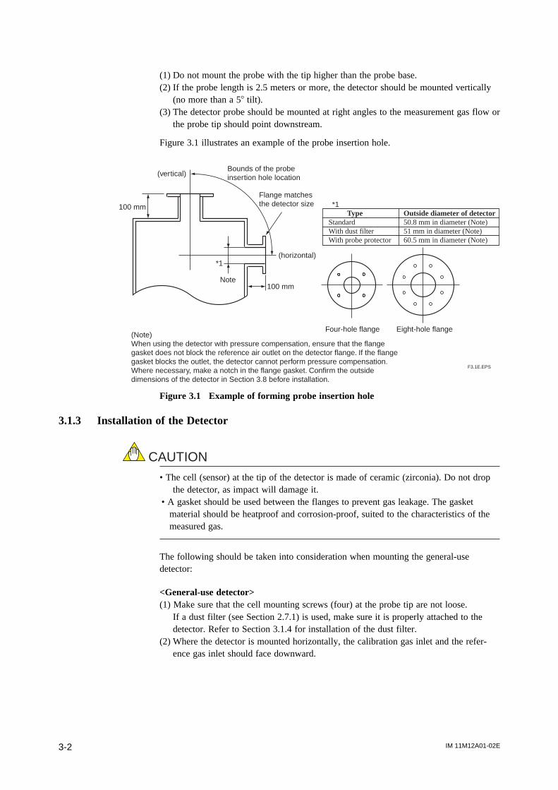
IM 11M12A01-02E3-2
(1) Do not mount the probe with the tip higher than the probe base.(2) If the probe length is 2.5 meters or more, the detector should be mounted vertically
(no more than a 58 tilt).(3) The detector probe should be mounted at right angles to the measurement gas flow or
the probe tip should point downstream.
Figure 3.1 illustrates an example of the probe insertion hole.
100 mm
100 mm
F3.1E.EPS
(vertical)Bounds of the probe insertion hole location
Flange matches the detector size
(horizontal)
(Note) When using the detector with pressure compensation, ensure that the flange gasket does not block the reference air outlet on the detector flange. If the flange gasket blocks the outlet, the detector cannot perform pressure compensation. Where necessary, make a notch in the flange gasket. Confirm the outside dimensions of the detector in Section 3.8 before installation.
Note
Type Outside diameter of detectorStandard 50.8 mm in diameter (Note)With dust filter 51 mm in diameter (Note)With probe protector 60.5 mm in diameter (Note)
Four-hole flange Eight-hole flange
*1
*1
Figure 3.1 Example of forming probe insertion hole
3.1.3 Installation of the Detector
CAUTION
• The cell (sensor) at the tip of the detector is made of ceramic (zirconia). Do not dropthe detector, as impact will damage it.
• A gasket should be used between the flanges to prevent gas leakage. The gasketmaterial should be heatproof and corrosion-proof, suited to the characteristics of themeasured gas.
The following should be taken into consideration when mounting the general-usedetector:
<General-use detector>(1) Make sure that the cell mounting screws (four) at the probe tip are not loose.
If a dust filter (see Section 2.7.1) is used, make sure it is properly attached to thedetector. Refer to Section 3.1.4 for installation of the dust filter.
(2) Where the detector is mounted horizontally, the calibration gas inlet and the refer-ence gas inlet should face downward.
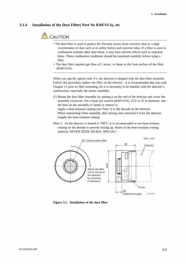
IM 11M12A01-02E 3-3
3. Installation
3.1.4 Installation of the Dust Filter( Part No K9471UA), etc
CAUTION
• The dust filter is used to protect the Zirconia sensor from corrosive dust or a highconcentration of dust such as in utility boilers and concrete kilns. If a filter is used incombustion systems other than these, it may have adverse effects such as responsedelay. These combustion conditions should be examined carefully before using afilter.
• The dust filter requires gas flow of 1 m/sec. or faster at the front surface of the filter(K9471UA).
When you specify option code /F1, the detector is shipped with the dust filter mounted.Follow this procedure replace the filter on the detector . It is recommended that you readChapter 11 prior to filter mounting, for it is necessary to be familiar with the detector’sconstruction, especially the sensor assembly.
(1) Mount the dust filter assembly by putting it on the end of the detector and screw theassembly clockwise. Put a hook pin wrench (K9471UX), [52 to 55 in diameter, intothe hole on the assembly to fasten or remove it.Apply a heat-resistant coating (see Note 1) to the threads on the detector.When remounting Filter assembly after having once removed it from the detector,reapply the heat-resistant coating.
Note 1: As the detector is heated to 7008C, it is recommended to use heat-resistantcoating on the threads to prevent seizing up. Name of the heat-resistant coatingmaterial: NEVER SEIZE NICKEL SPECIAL”.
Additional length
SiC Carborundum filter
f51
32
10F3.2E.EPS
Screw
Detector
Attach the filterunit to the tip of the detector by screwing it clockwise.
Unit : mm
Figure 3.2 Installation of the dust filter
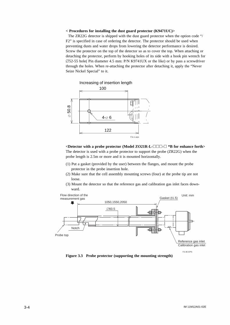
IM 11M12A01-02E3-4
< Procedures for installing the dust guard protector (K9471UC)> The ZR22G detector is shipped with the dust guard protector when the option code “/F2” is specified in case of ordering the detector. The protector should be used whenpreventing dusts and water drops from lowering the detector performance is desired.Screw the protector on the top of the detector so as to cover the top. When attaching ordetaching the protector, perform by hooking holes of its side with a hook pin wrench for[52-55 hole( Pin diameter 4.5 mm: P/N K9741UX or the like) or by pass a screwdriverthrough the holes. When re-attaching the protector after detaching it, apply the “NeverSeize Nickel Special” to it.
4-[ 6
122
[50
.8
100Increasing of insertion length
F11-1.eps
<Detector with a probe protector (Model ZO21R-L-hhh-h *B for enhance forth>The detector is used with a probe protector to support the probe (ZR22G) when theprobe length is 2.5m or more and it is mounted horizontally.
(1) Put a gasket (provided by the user) between the flanges, and mount the probeprotector in the probe insertion hole.
(2) Make sure that the cell assembly mounting screws (four) at the probe tip are notloose.
(3) Mount the detector so that the reference gas and calibration gas inlet faces down-ward.
1050,1550,2050
Notch
Unit: mm
F3.3E.EPS
Gasket (t1.5)
Reference gas inletCalibration gas inlet
Flow direction of the measurement gas
[60.5
Probe top
Figure 3.3 Probe protector (supporting the mounting strength)

IM 11M12A01-02E 3-5
3. Installation
<Detector with a probe protector (Model ZO21R-L-hhh-h *B for dust wearprodect>
The detector is used with a probe protector to prevent the sensor from being worn bydust particles when there is a high concentration of dust and gas flow exceeds 10m/s(fine-carbon boiler or fluid-bed furnace).
(1) Put a gasket (provided by the user) between the flanges, and mount the probeprotector in the probe insertion hole. The probe protector should be installed so thatthe notch is downstream of the measurement gas flow.
(2) Make sure that the cell assembly mounting screws (four) at the probe tip are notloose.
(3) Where the detector is mounted horizontally, the reference gas and calibration gasinlet should face downward.
CAUTION
When the probe protector is used in the Zirconia Oxygen Analyzer version withpressure compensation (-P), instrument air leaking from the probe protector mayaffect the measured value.
Direction of the measurement gas flow
Mount the protector so that the notch isor the downstream side of the gas flow.
Reference gas inletCalibration gas inlet
Unit: mm
F3.4E.EPS
Probe top
1050,1550,2050Gasket (t1.5)
Figure 3.4 Mounting of detector with a probe protector
IM 11M12A01-02E3-6
3.2 Installation of the Detector (Model ZR22G-015)
3.2.1 Installation Location
This model detector is used with the High-temperature Probe Adapter (Model ZO21P-H)when the temperature of sample gas exceeds 7008C, or when it is required due tomaintenance spaces.
The following should be taken into consideration when installing the detector:
(1) Easy and safe access to the detector for checking and maintenance work.(2) Ambient temperature of not more than 1508C and the terminal box should not be
exposed to radiant heat.(3) A clean environment without any corrosive gases.(4) No vibration.(5) The measured gas should satisfy the specifications described in Chapter 2.
3.2.2 Usage of the High-temperature Probe Adapter (Model ZO21P-H)
During analysis, the surface temperature of the probe adapter should be within the rangefrom the dew point of the measured gas and 3008C to prevent ejector clogging, gasketdeterioration or bolt scoring.
Where the dew point of the measured gas is not known, keep within the range 2008C to3008C.
The temperature shall be measured at the probe in the probe adapter and the surface ofthe blind flange at the opposite side.
When the surface temperature is not within the above range, the following measures canbe taken to change the temperature.
<When the surface temperature exceeds 3008C>(1) When the furnace pressure is negative, lower the pressure setting to reduce induction
flow of the measurement gas.Refer to Section 2.7.3, Auxiliary Ejector for High Temperature, for the setting ofinduction flow.When you reduce induction flow, ensure that the ejector inducts air when the furnacepressure fluctuates.
(2) When the furnace pressure is positive, close the needle valve for the sample gasoutlet to reduce the exhaust gas flow. Refer to Section 4.1.4, Piping to the High-temperature Probe Adapter.
(3) When the probe adapter is surrounded by a heat insulator, remove the heat insulator.Ensure that the temperature of the probe adapter does not fall below the dew point ofthe gas in winter.
(4) To prevent temperature rises due to radiant heat, insert heat insulator between thewall of the furnace and the probe adapter.
(5) To prevent temperature rises from thermal conduction, place the mounting flange asfar from the wall of the furnace as possible.

IM 11M12A01-02E 3-7
3. Installation
<When the surface temperature is less than 2008C or the dew point of the measure-ment gas>
(1) When the furnace pressure is negative, raise the analyzer pressure to increaseinduction flow of the measurement gas.Refer to Section 2.7.3, Auxiliary Ejector for High-temperature Use, for the setting ofinduction flow.If there is much dust in the gas, the ejector may become clogg is induction flowincreases.
(2) When the furnace pressure is positive, open the needle valve for the sample gasoutlet to increase the gas flow.Refer to Section 4.1.4, Piping to the High-temperature Probe Adapter.
(3) Warm the probe adapter. Refer to Section 4.2.4, Piping to the High-temperatureProbe Adapter. Ensure that its temperature does not drop below freezing point inwinter.
(4) When the surface temperature is still less than 2008C or the dew point of the mea-surement gas, even if the above measures have been taken, warm the probe adapterusing a heat source such as steam.
3.2.3 Probe Insertion Hole
A high-temperature detector consists of a ZR22G-015 Detector and ZO21P High-temperature Probe Adapter. When forming the probe insertion hole, the following shouldbe taken into consideration:
(1) If the probe is made of silicon carbide (SiC), the probe hole should be formed so thatthe probe is mounted vertically (no more than a 58 tilt).
(2) In the case where the probe is made of stainless steel and the probe adapter is to bemounted horizontally, the probe hole should be formed so that the probe tip is nothigher than the probe base.
Figure 3.5 illustrates examples of the probe insertion hole.
100mm
JIS 5K 50 FF (equivalent)
or ANSI Class 150 4 RF
(equivalent) flange
100mm
A space of 52 mm or more
in diameter, and long enough
for the length of the probe
The allowable margin for probe
tilt is within 658.
An SiC probe shall be mounted vertically.
A space of 52 mm or
more in diameter, and
long enough the length
of the probe
Never mount the probe
with its tip higher than
the base
Horizontal mounting is used with a SUS probe.
JIS 5K 50 FF (equivalent) or
ANSI Class 150 4 RF
(equivalent) flange
F3.5E.EPS
Figure 3.5 Examples of the probe insertion hole
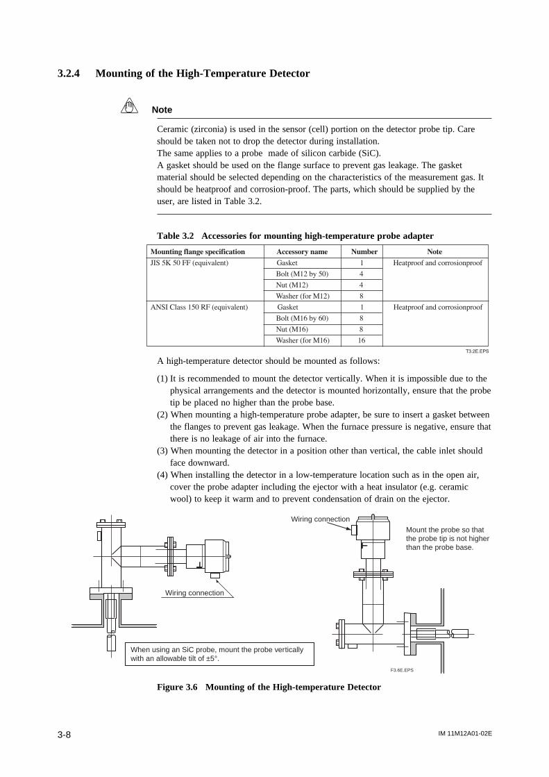
IM 11M12A01-02E3-8
3.2.4 Mounting of the High-Temperature Detector
Note
Ceramic (zirconia) is used in the sensor (cell) portion on the detector probe tip. Careshould be taken not to drop the detector during installation.The same applies to a probe made of silicon carbide (SiC).A gasket should be used on the flange surface to prevent gas leakage. The gasketmaterial should be selected depending on the characteristics of the measurement gas. Itshould be heatproof and corrosion-proof. The parts, which should be supplied by theuser, are listed in Table 3.2.
Table 3.2 Accessories for mounting high-temperature probe adapter
Mounting flange specification Accessory name Number Note
JIS 5K 50 FF (equivalent) Gasket 1 Heatproof and corrosionproof
Bolt (M12 by 50) 4
Nut (M12) 4
Washer (for M12) 8
ANSI Class 150 RF (equivalent) Gasket 1 Heatproof and corrosionproof
Bolt (M16 by 60) 8
Nut (M16) 8
Washer (for M16) 16
T3.2E.EPS
A high-temperature detector should be mounted as follows:
(1) It is recommended to mount the detector vertically. When it is impossible due to thephysical arrangements and the detector is mounted horizontally, ensure that the probetip be placed no higher than the probe base.
(2) When mounting a high-temperature probe adapter, be sure to insert a gasket betweenthe flanges to prevent gas leakage. When the furnace pressure is negative, ensure thatthere is no leakage of air into the furnace.
(3) When mounting the detector in a position other than vertical, the cable inlet shouldface downward.
(4) When installing the detector in a low-temperature location such as in the open air,cover the probe adapter including the ejector with a heat insulator (e.g. ceramicwool) to keep it warm and to prevent condensation of drain on the ejector.
Wiring connection
Wiring connection
When using an SiC probe, mount the probe vertically with an allowable tilt of ±5°.
Mount the probe so thatthe probe tip is not higher than the probe base.
F3.6E.EPS
Figure 3.6 Mounting of the High-temperature Detector
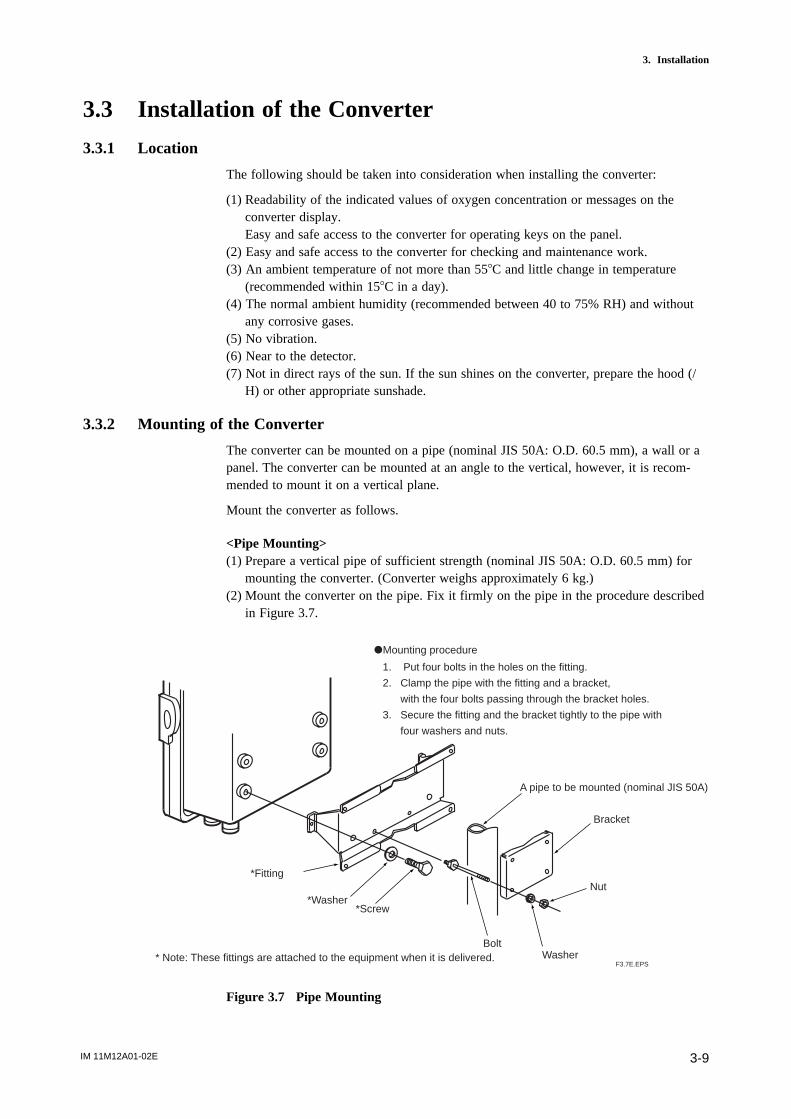
IM 11M12A01-02E 3-9
3. Installation
3.3 Installation of the Converter
3.3.1 Location
The following should be taken into consideration when installing the converter:
(1) Readability of the indicated values of oxygen concentration or messages on theconverter display.Easy and safe access to the converter for operating keys on the panel.
(2) Easy and safe access to the converter for checking and maintenance work.(3) An ambient temperature of not more than 558C and little change in temperature
(recommended within 158C in a day).(4) The normal ambient humidity (recommended between 40 to 75% RH) and without
any corrosive gases.(5) No vibration.(6) Near to the detector.(7) Not in direct rays of the sun. If the sun shines on the converter, prepare the hood (/
H) or other appropriate sunshade.
3.3.2 Mounting of the Converter
The converter can be mounted on a pipe (nominal JIS 50A: O.D. 60.5 mm), a wall or apanel. The converter can be mounted at an angle to the vertical, however, it is recom-mended to mount it on a vertical plane.
Mount the converter as follows.
<Pipe Mounting>(1) Prepare a vertical pipe of sufficient strength (nominal JIS 50A: O.D. 60.5 mm) for
mounting the converter. (Converter weighs approximately 6 kg.)(2) Mount the converter on the pipe. Fix it firmly on the pipe in the procedure described
in Figure 3.7.
A pipe to be mounted (nominal JIS 50A)
Bracket
Nut
WasherBolt
*Screw*Washer
*Fitting
* Note: These fittings are attached to the equipment when it is delivered.F3.7E.EPS
dMounting procedure
1. Put four bolts in the holes on the fitting.
2. Clamp the pipe with the fitting and a bracket,
with the four bolts passing through the bracket holes.
3. Secure the fitting and the bracket tightly to the pipe with
four washers and nuts.
Figure 3.7 Pipe Mounting
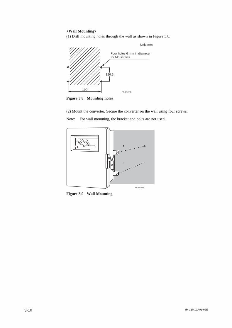
IM 11M12A01-02E3-10
<Wall Mounting>(1) Drill mounting holes through the wall as shown in Figure 3.8.
190
126.5
Four holes 6 mm in diameter for M5 screws
Unit: mm
F3.8E.EPS
Figure 3.8 Mounting holes
(2) Mount the converter. Secure the converter on the wall using four screws.
Note: For wall mounting, the bracket and bolts are not used.
F3.9E.EPS
Figure 3.9 Wall Mounting
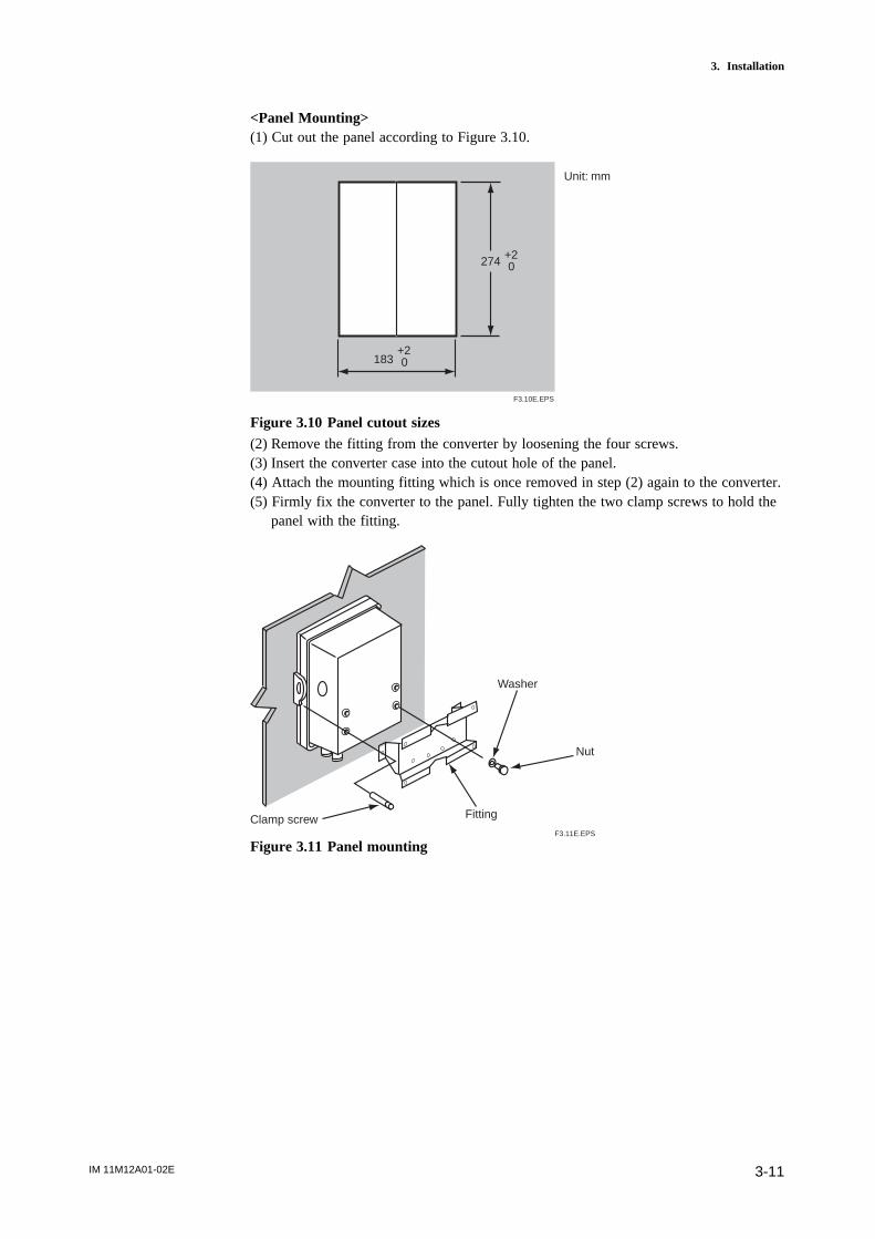
IM 11M12A01-02E 3-11
3. Installation
<Panel Mounting>(1) Cut out the panel according to Figure 3.10.
274 +20
183+20
F3.10E.EPS
Unit: mm
Figure 3.10 Panel cutout sizes(2) Remove the fitting from the converter by loosening the four screws.(3) Insert the converter case into the cutout hole of the panel.(4) Attach the mounting fitting which is once removed in step (2) again to the converter.(5) Firmly fix the converter to the panel. Fully tighten the two clamp screws to hold the
panel with the fitting.
Clamp screw
Washer
Nut
Fitting
F3.11E.EPS
Figure 3.11 Panel mounting
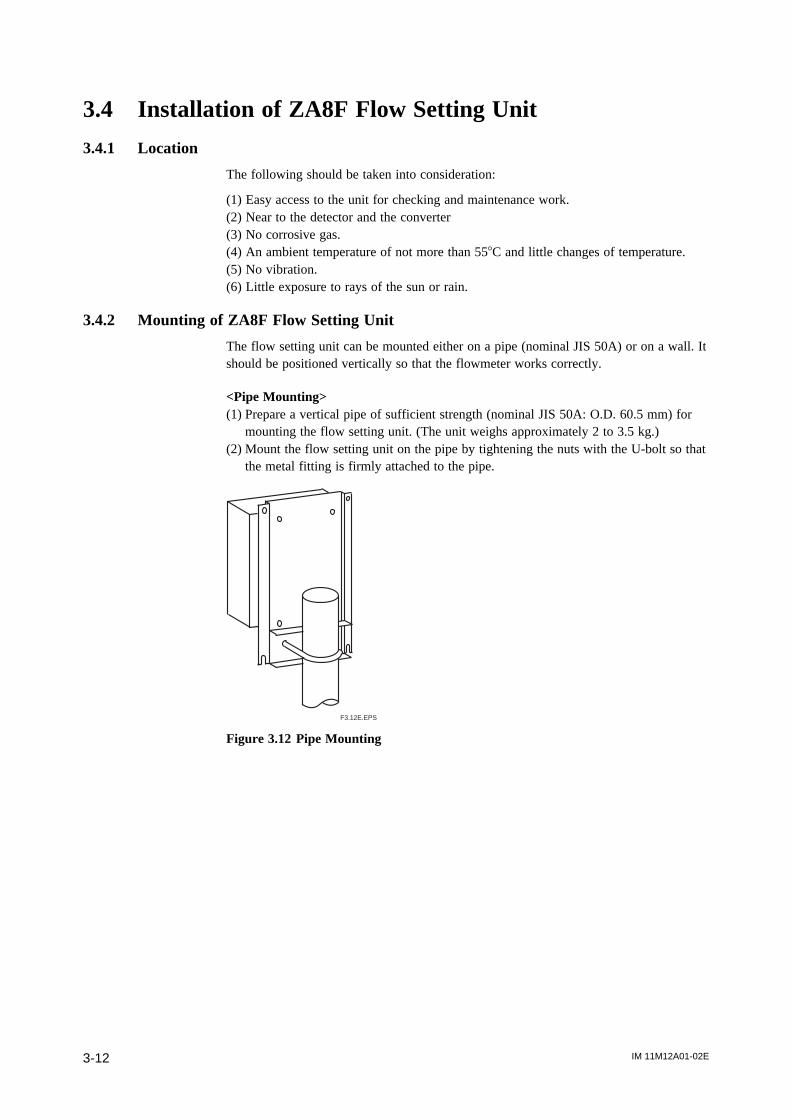
IM 11M12A01-02E3-12
3.4 Installation of ZA8F Flow Setting Unit
3.4.1 Location
The following should be taken into consideration:
(1) Easy access to the unit for checking and maintenance work.(2) Near to the detector and the converter(3) No corrosive gas.(4) An ambient temperature of not more than 558C and little changes of temperature.(5) No vibration.(6) Little exposure to rays of the sun or rain.
3.4.2 Mounting of ZA8F Flow Setting Unit
The flow setting unit can be mounted either on a pipe (nominal JIS 50A) or on a wall. Itshould be positioned vertically so that the flowmeter works correctly.
<Pipe Mounting>(1) Prepare a vertical pipe of sufficient strength (nominal JIS 50A: O.D. 60.5 mm) for
mounting the flow setting unit. (The unit weighs approximately 2 to 3.5 kg.)(2) Mount the flow setting unit on the pipe by tightening the nuts with the U-bolt so that
the metal fitting is firmly attached to the pipe.
F3.12E.EPS
Figure 3.12 Pipe Mounting

IM 11M12A01-02E 3-13
3. Installation
<Wall Mounting>(1) Make a hole in the wall as illustrated in Figure 3.13.
223
140
F3.13E.EPS
4 - f6.5 hole, or M6 screw
Unit : mm
Figure 3.13 Mounting holes
(2) Mount the flow setting unit. Remove the pipe mounting parts from the mount fittingsof the flow setting unit and attach the unit securely on the wall with four screws.
F3.14E.EPS
Figure 3.14 Wall mounting

IM 11M12A01-02E3-14
3.5 Installation of ZR40H Automatic Calibration Unit
3.5.1 Location
The following should be taken into consideration:
(1) Easy access to the unit for checking and maintenance work.(2) Near to the detector and the converter(3) No corrosive gas.(4) An ambient temperature of not more than 558C and little change of temperature.(5) No vibration.(6) Little exposure to rays of the sun or rain.
3.5.2 Mounting of ZR40H Automatic Calibration Unit
The Automatic Calibration Unit can be mounted either on a pipe (nominal JIS 50A ) or
on a wall. It should be positioned vertically so that the flowmeter works correctly.
<Pipe Mounting>
(1) Prepare a vertical pipe of sufficient strength (nominal JIS 50A: O.D. 60.5 mm) formounting of Automatic Calibration Unit. (The unit weights approximately 3.5 kg.)
(2) Mount the Automatic Calibration Unit on the pipe by tightening the nuts with the U-bolt so that the metal fitting is firmly attached to the pipe.
F3.12E.EPS
Figure 3.15 Pipe Mounting
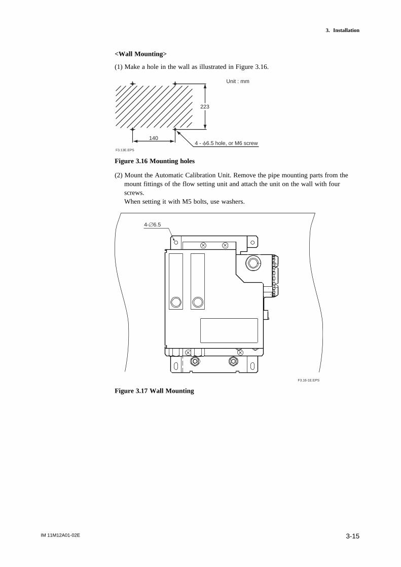
IM 11M12A01-02E 3-15
3. Installation
<Wall Mounting>
(1) Make a hole in the wall as illustrated in Figure 3.16.
223
140
F3.13E.EPS
4 - f6.5 hole, or M6 screw
Unit : mm
Figure 3.16 Mounting holes
(2) Mount the Automatic Calibration Unit. Remove the pipe mounting parts from themount fittings of the flow setting unit and attach the unit on the wall with fourscrews.When setting it with M5 bolts, use washers.
F3.16-1E.EPS
4-[6.5
Figure 3.17 Wall Mounting
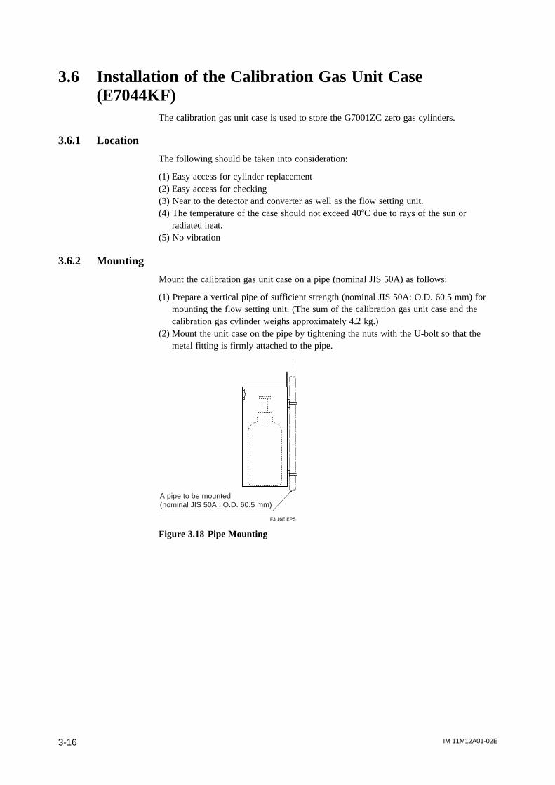
IM 11M12A01-02E3-16
3.6 Installation of the Calibration Gas Unit Case(E7044KF)
The calibration gas unit case is used to store the G7001ZC zero gas cylinders.
3.6.1 Location
The following should be taken into consideration:
(1) Easy access for cylinder replacement(2) Easy access for checking(3) Near to the detector and converter as well as the flow setting unit.(4) The temperature of the case should not exceed 408C due to rays of the sun or
radiated heat.(5) No vibration
3.6.2 Mounting
Mount the calibration gas unit case on a pipe (nominal JIS 50A) as follows:
(1) Prepare a vertical pipe of sufficient strength (nominal JIS 50A: O.D. 60.5 mm) formounting the flow setting unit. (The sum of the calibration gas unit case and thecalibration gas cylinder weighs approximately 4.2 kg.)
(2) Mount the unit case on the pipe by tightening the nuts with the U-bolt so that themetal fitting is firmly attached to the pipe.
F3.16E.EPS
A pipe to be mounted (nominal JIS 50A : O.D. 60.5 mm)
Figure 3.18 Pipe Mounting
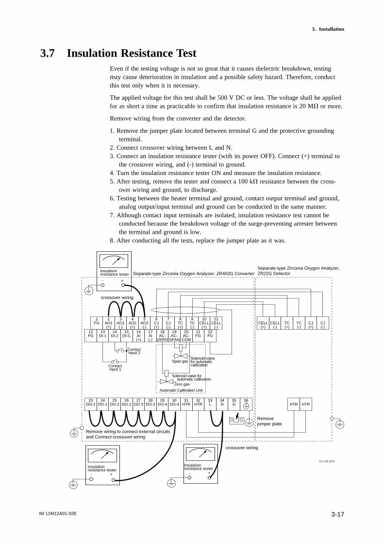
IM 11M12A01-02E 3-17
3. Installation
3.7 Insulation Resistance TestEven if the testing voltage is not so great that it causes dielectric breakdown, testingmay cause deterioration in insulation and a possible safety hazard. Therefore, conductthis test only when it is necessary.
The applied voltage for this test shall be 500 V DC or less. The voltage shall be appliedfor as short a time as practicable to confirm that insulation resistance is 20 MV or more.
Remove wiring from the converter and the detector.
1. Remove the jumper plate located between terminal G and the protective groundingterminal.
2. Connect crossover wiring between L and N.3. Connect an insulation resistance tester (with its power OFF). Connect (+) terminal to
the crossover wiring, and (-) terminal to ground.4. Turn the insulation resistance tester ON and measure the insulation resistance.5. After testing, remove the tester and connect a 100 kV resistance between the cross-
over wiring and ground, to discharge.6. Testing between the heater terminal and ground, contact output terminal and ground,
analog output/input terminal and ground can be conducted in the same manner.7. Although contact input terminals are isolated, insulation resistance test cannot be
conducted because the breakdown voltage of the surge-preventing arrester betweenthe terminal and ground is low.
8. After conducting all the tests, replace the jumper plate as it was.
1FG
2AO1(+)
3AO1(-)
4AO2(+)
5AO2(-)
6CJ(+)
7CJ(-)
8TC(+)
9TC(-)
10CELL
(+)
11CELL
(-)12FG
13DI-1
14DI-2
15DI-C
16AI(+)
17AI(-)
18AC-
ZERO
19AC-
SPAN
20AC-
COM
21FG
22FG
CELL(+)
CELL(-)
TC(+)
TC(-)
CJ(+)
CJ(-)
23DO-1
24DO-1
25DO-2
26DO-2
27DO-3
28DO-3
29DO-4
30DO-4
31HTR
32HTR
33L
34N
35G
36HTR HTR
Contact input 2
Contact input 1
Solenoid valve for automaticcalibration
Solenoid valve for automatic calibration
Span gas
Zero gas
Automatic Calibration Unit
Separate-type Zirconia Oxygen Analyzer, ZR402G ConverterSeparate-type Zirconia Oxygen Analyzer, ZR22G Detector
Insulation resistance tester
Insulation resistance tester
+-
+-
Insulation resistance tester
Removejumper plate
Remove wiring to connect external circuits and Connect crossover wiring
F3.17E.EPS
+-
crossover wiring
crossover wiring
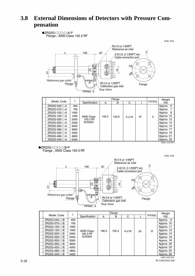
IM 11M12A01-02E3-18
3.8 External Dimensions of Detectors with Pressure Com-pensation
dZR22G-hhh-h-A-PFlange ; ANSI Class 150 2 RF
Unit: mm
fB
fA
Flange
12B01-01E.EPS
Model, Code Specification
Flange
A B C t
Weightskgd
ZR22G-040-h-A
ZR22G-070-h-A
ZR22G-100-h-A
ZR22G-150-h-A
ZR22G-200-h-A
ZR22G-250-h-A
ZR22G-300-h-A
ZR22G-360-h-A
ZR22G-420-h-A
ZR22G-480-h-A
ZR22G-540-h-A
400
700
1000
1500
2000
2500
3000
3600
4200
4800
5400
ANSI Class150 2 RFSUS304
152.4 120.6 4-f19 19
L PIPING
A
Approx. 6
Approx. 7
Approx. 8
Approx. 10
Approx. 12
Approx. 14
Approx. 15
Approx. 17
Approx. 19
Approx. 21
Approx. 23
C
Rc1/4 or 1/4NPTCalibration gas inlet
25
48
Reference gas outlet
PIPING : A
PIPING:BFlange
Stop Valve
33
Rc1/4 or 1/4NPTReference air inlet
2-G1/2, 2-1/2NPT etc.Cable connection port
156 87L
t
*1
dZR22G-hhh-h-B-PFlange ; ANSI Class 150 3 RF
Unit: mm
12B01-02E.EPS
Model, Code Specification
Flange
A B C t
Weightskgd
ZR22G-040-h-B
ZR22G-070-h-B
ZR22G-100-h-B
ZR22G-150-h-B
ZR22G-200-h-B
ZR22G-250-h-B
ZR22G-300-h-B
ZR22G-360-h-B
ZR22G-420-h-B
ZR22G-480-h-B
ZR22G-540-h-B
400
700
1000
1500
2000
2500
3000
3600
4200
4800
5400
ANSI Class150 3 RFSUS304
190.5 152.4 4-f19 24
L PIPING
B
Approx. 9
Approx. 10
Approx. 11
Approx. 13
Approx. 14
Approx. 16
Approx. 18
Approx. 20
Approx. 22
Approx. 24
Approx. 26
Rc1/4 or 1/4NPTCalibration gas inlet
25
48
Reference gas outlet
PIPING : A
PIPING:B
fB
fA
FlangeFlange
Stop Valve
42
Rc1/4 or 1/4NPTReference air inlet
2-G1/2, 2-1/2NPT etc.Cable connection port
156 87 CL
t
*1
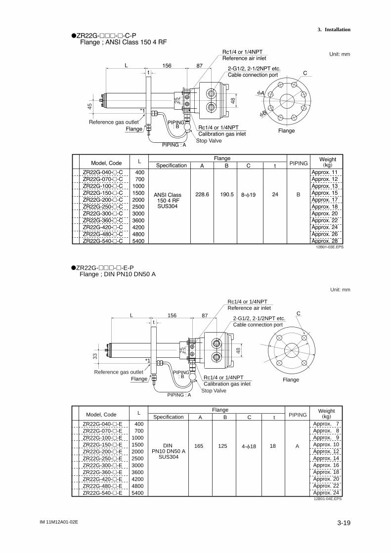
IM 11M12A01-02E 3-19
3. InstallationdZR22G-hhh-h-C-P
Flange ; ANSI Class 150 4 RF
Unit: mm
fB
fA
C
Flange
Approx. 11
Approx. 12
Approx. 13
Approx. 15
Approx. 17
Approx. 18
Approx. 20
Approx. 22
Approx. 24
Approx. 26
Approx. 28
Model, Code Specification
Flange
A B C t
Weightskgd
ZR22G-040-h-C
ZR22G-070-h-C
ZR22G-100-h-C
ZR22G-150-h-C
ZR22G-200-h-C
ZR22G-250-h-C
ZR22G-300-h-C
ZR22G-360-h-C
ZR22G-420-h-C
ZR22G-480-h-C
ZR22G-540-h-C
400
700
1000
1500
2000
2500
3000
3600
4200
4800
5400
ANSI Class150 4 RFSUS304
228.6 190.5 8-f19 24
L PIPING
B
12B01-03E.EPS
Rc1/4 or 1/4NPTCalibration gas inlet
25
48
Reference gas outlet
PIPING : A
PIPING: BFlange
Stop Valve
45
Rc1/4 or 1/4NPTReference air inlet
2-G1/2, 2-1/2NPT etc.Cable connection port
156 87L
t
*1
dZR22G-hhh-h-E-P Flange ; DIN PN10 DN50 A
Unit: mm
12B01-04E.EPS
C
Flange
Model, Code SpecificationFlange
A B C tWeight
skgd
DIN PN10 DN50 A
SUS304
165 125 4-f18 18
L PIPING
A
Approx. 7Approx. 8
Approx. 9Approx. 10Approx. 12Approx. 14Approx. 16Approx. 18Approx. 20Approx. 22Approx. 24
ZR22G-040-h-EZR22G-070-h-EZR22G-100-h-EZR22G-150-h-EZR22G-200-h-EZR22G-250-h-EZR22G-300-h-EZR22G-360-h-EZR22G-420-h-EZR22G-480-h-EZR22G-540-h-E
400700
100015002000250030003600420048005400
Rc1/4 or 1/4NPTCalibration gas inlet
25 48
Reference gas outlet
PIPING : A
PIPING: BFlange
Stop Valve
33
Rc1/4 or 1/4NPTReference air inlet
2-G1/2, 2-1/2NPT etc.Cable connection port
156 87Lt
*1

IM 11M12A01-02E3-20
dZR22G-hhh-h-F-P Flange ; DIN PN10 DN80 A
Unit: mm
12B01-05E.EPS
C
Flange
Model, Code SpecificationFlange
A B C tWeight
skgd
DIN PN10 DN80 A
SUS304
200 160 8-f18 20
L PIPING
B
ZR22G-040-h-FZR22G-070-h-FZR22G-100-h-FZR22G-150-h-FZR22G-200-h-FZR22G-250-h-FZR22G-300-h-FZR22G-360-h-FZR22G-420-h-FZR22G-480-h-FZR22G-540-h-F
400700
100015002000250030003600420048005400
Approx. 8Approx. 10
Approx. 11Approx. 12Approx. 14Approx. 16Approx. 18Approx. 20Approx. 22Approx. 24Approx. 26
Rc1/4 or 1/4NPTCalibration gas inlet
25 48
Reference gas outlet
PIPING : A
PIPING: BFlange
Stop Valve
42
Rc1/4 or 1/4NPTReference air inlet
2-G1/2, 2-1/2NPT etc.Cable connection port
156 87Lt
*1
dZR22G-hhh-h-G-P Flange ; DIN PN10 DN100 A
Unit: mm
12B01-06E.EPS
fB
fA
C
Flange
Model, Code SpecificationFlange
A B C tWeight
skgdZR22G-040-h-GZR22G-070-h-GZR22G-100-h-GZR22G-150-h-GZR22G-200-h-GZR22G-250-h-GZR22G-300-h-GZR22G-360-h-GZR22G-420-h-GZR22G-480-h-GZR22G-540-h-G
DIN PN10 DN100 A
SUS304
220 180 8-f18 20
L PIPING
B
Approx. 9Approx. 11
Approx. 12Approx. 13Approx. 15Approx. 17Approx. 19Approx. 21Approx. 23Approx. 25Approx. 27
400700
100015002000250030003600420048005400
Rc1/4 or 1/4NPTCalibration gas inlet
25 48
Reference gas outlet
PIPING : A
PIPING:BFlange
Stop Valve
45
Rc1/4 or 1/4NPTReference air inlet
2-G1/2, 2-1/2NPT etc.Cable connection port
156 87Lt
*1

IM 11M12A01-02E 3-21
3. InstallationdZR22G-hhh-h-K-P Flange ; JIS 5K 65 FF Unit: mm
12B01-07E.EPS
fB
fA
C
Flange
FlangeModel, Code Specification A B C t
Weightskgd
ZR22G-040-h-KZR22G-070-h-KZR22G-100-h-KZR22G-150-h-KZR22G-200-h-KZR22G-250-h-KZR22G-300-h-KZR22G-360-h-KZR22G-420-h-KZR22G-480-h-KZR22G-540-h-K
JIS 5K 65 FFSUS304
155 130 4-f15 14
L PIPING
4
400700
100015002000250030003600420048005400
Approx. 6Approx. 7
Approx. 8Approx. 10Approx. 12Approx. 14Approx. 15Approx. 17Approx. 19Approx. 21Approx. 23
Rc1/4 or 1/4NPTCalibration gas inlet
25 48
Reference gas outlet
PIPING : A
PIPING: BFlange
Stop Valve
33
Rc1/4 or 1/4NPTReference air inlet
2-G1/2, 2-1/2NPT etc.Cable connection port
156 87Lt
*1
dZR22G-hhh-h-L-P Flange ; JIS 10K 65 FF
Unit: mm
12B01-08E.EPS
fB
fA
C
Flange
Model, Code SpecificationFlange
A B C tWeight
skgd
JIS 10K 65 FFSUS304
175 140 4-f19 18
L PIPING
A
ZR22G-040-h-LZR22G-070-h-LZR22G-100-h-LZR22G-150-h-LZR22G-200-h-LZR22G-250-h-LZR22G-300-h-LZR22G-360-h-LZR22G-420-h-LZR22G-480-h-LZR22G-540-h-L
400700
100015002000250030003600420048005400
Approx. 7Approx. 8
Approx. 9Approx. 11Approx. 13Approx. 14Approx. 16Approx. 18Approx. 20Approx. 22Approx. 24
Rc1/4 or 1/4NPTCalibration gas inlet
25 48
Reference gas outlet
PIPING : A
PIPING: BFlange
Stop Valve
33
Rc1/4 or 1/4NPTReference air inlet
2-G1/2, 2-1/2NPT etc.Cable connection port
156 87Lt
*1

IM 11M12A01-02E3-22
dZR22G-hhh-h-M-PFlange ; JIS 10K 80 FF Unit: mm
12B01-09E.EPS
fB
fA
C
Flange
Model, Code Specification
Flange
A B C t
Weightskgd
JIS 10K 80 FFSUS304
185 150 8-f19 18
L PIPING
B
Approx. 7
Approx. 8
Approx. 9
Approx. 11
Approx. 13
Approx. 15
Approx. 16
Approx. 18
Approx. 20
Approx. 22
Approx. 24
ZR22G-040-h-M
ZR22G-070-h-M
ZR22G-100-h-M
ZR22G-150-h-M
ZR22G-200-h-M
ZR22G-250-h-M
ZR22G-300-h-M
ZR22G-360-h-M
ZR22G-420-h-M
ZR22G-480-h-M
ZR22G-540-h-M
400
700
1000
1500
2000
2500
3000
3600
4200
4800
5400
Rc1/4 or 1/4NPTCalibration gas inlet
25
48
Reference gas outlet
PIPING : A
PIPING: BFlange
Stop Valve
42
Rc1/4 or 1/4NPTReference air inlet
2-G1/2, 2-1/2NPT etc.Cable connection port
156 87L
t
*1
dZR22G-hhh-h-P-P
Flange ; JIS 10K 100 FF
12B01-10E.EPS
fB
fA
C
Flange
Model, CodeSpecification
Flange
A B C t
Weight
skgdZR22G-040-h-P
ZR22G-070-h-P
ZR22G-100-h-P
ZR22G-150-h-P
ZR22G-200-h-P
ZR22G-250-h-P
ZR22G-300-h-P
ZR22G-360-h-P
ZR22G-420-h-P
ZR22G-480-h-P
ZR22G-540-h-P
400
700
1000
1500
2000
2500
3000
3600
4200
4800
5400
JIS 10K 100 FF
SUS304
210 175 8-f19 18
L PIPING
B
Approx. 8
Approx. 10
Approx. 11
Approx. 12
Approx. 14
Approx. 16
Approx. 18
Approx. 20
Approx. 22
Approx. 24
Approx. 26
Rc1/4 or 1/4NPT
Calibration gas inlet
25
48
Reference gas outlet
PIPING : A
PIPING: B
Flange
Stop Valve
45
Rc1/4 or 1/4NPT
Reference air inlet
2-G1/2, 2-1/2NPT etc.
Cable connection port
156 87L
t
*1
Unit: mm

IM 11M12A01-02E 3-23
3. InstallationdZR22G-hhh-h-R-P Flange ; JPI Class 150 4 RF
12B01-12E.EPS
fB
fA
C
Flange
Approx. 11Approx. 12
Approx. 13Approx. 15Approx. 17Approx. 19Approx. 20Approx. 22Approx. 24Approx. 26Approx. 28
Model, Code SpecificationFlange
A B C tWeight
skgd
229 190.5 8-f19 24
L PIPING
B
ZR22G-040-h-RZR22G-070-h-RZR22G-100-h-RZR22G-150-h-RZR22G-200-h-RZR22G-250-h-RZR22G-300-h-RZR22G-360-h-RZR22G-420-h-RZR22G-480-h-RZR22G-540-h-R
JPI Class150 4 RFSUS304
400700
100015002000250030003600420048005400
Rc1/4 or 1/4NPTCalibration gas inlet
25 48
Reference gas outlet
PIPING : A
PIPING: BFlange
Stop Valve
45
Rc1/4 or 1/4NPTReference air inlet
2-G1/2, 2-1/2NPT etc.Cable connection port
156 87Lt
*1
Unit: mm
dZR22G-hhh-h-S-P
Flange ; JPI Class 150 3 RF
12B01-13E.EPS
fB
fA
C
Flange
Model, CodeSpecification
Flange
A B C t
Weight
skgdZR22G-040-h-S
ZR22G-070-h-S
ZR22G-100-h-S
ZR22G-150-h-S
ZR22G-200-h-S
ZR22G-250-h-S
ZR22G-300-h-S
ZR22G-360-h-S
ZR22G-420-h-S
ZR22G-480-h-S
ZR22G-540-h-S
JPI Class
150 3 RF
SUS304
190 152.4 4-f19 24
L PIPING
B
Approx. 9
Approx. 10
Approx. 11
Approx. 13
Approx. 14
Approx. 16
Approx. 18
Approx. 20
Approx. 22
Approx. 24
Approx. 26
400
700
1000
1500
2000
2500
3000
3600
4200
4800
5400
Rc1/4 or 1/4NPT
Calibration gas inlet
25
48
Reference gas outlet
PIPING : A
PIPING: B
Flange
Stop Valve
42
Rc1/4 or 1/4NPT
Reference air inlet
2-G1/2, 2-1/2NPT etc.
Cable connection port
156 87L
t
*1
Unit: mm

IM 11M12A01-02E3-24
dZR22G-hhh-h-W-PFlange ; Westinghouse
Unit: mm
12B01-14E.EPS
fB
fA
C
Flange
Approx. 6
Approx. 7
Approx. 8
Approx. 10
Approx. 12
Approx. 14
Approx. 15
Approx. 17
Approx. 19
Approx. 21
Approx. 23
Model, Code Specification
Flange
A B C t
Weightskgd
ZR22G-040-h-W
ZR22G-070-h-W
ZR22G-100-h-W
ZR22G-150-h-W
ZR22G-200-h-W
ZR22G-250-h-W
ZR22G-300-h-W
ZR22G-360-h-W
ZR22G-420-h-W
ZR22G-480-h-W
ZR22G-540-h-W
Westinghouse 155 127 4-f11.5 14
L PIPING
A
400
700
1000
1500
2000
2500
3000
3600
4200
4800
5400
Rc1/4 or 1/4NPTCalibration gas inlet
25
48
Reference gas outlet
PIPING : A
PIPING: BFlange
Stop Valve
33
Rc1/4 or 1/4NPTReference air inlet
2-G1/2, 2-1/2NPT etc.Cable connection port
156 87L
t
*1

IM 11M12A01-02E 4-1
4. Piping
4. Piping
This chapter describes piping procedures based on three typical system configurationsfor EXAxt ZR Separate-type Zirconia Oxygen Analyzer.
• Ensure that each check valve, stop valve and joint used for piping do not allowleakage. Especially, if there is any leakage of the calibration gas from pipes and joints,it may cause clogging of the pipes or incorrect calibration.
• Be sure to conduct leakage test after piping.• Basically, apply instrument air (dehumidified by cooling to the dew point -208C or
lower, and removing any dust, oil mist and the like) for the reference gas.• When the instrument uses natural convection for reference gas, ambient air near the
detector is used for reference gas; therefore the accuracy of analysis will be affectedby ambient humidity changes or the like. If more accurate analysis is necessary, useinstrument air (dehumidified to the dew point -208C or lower, and removing any dust,oil mist and the like) for reference gas.Stable analyzing can be conducted when using instrument air.
4.1 Piping for System 1The piping in System 1 is illustrated in Figure 4.1.
~
~
Model ZO21S Standard gas unit
EXA ZR402G
Model ZR22G Separate type Zirconia Oxygen Analyzer, Detector
Model ZR402G Converter
Stop valve
Calibration gas
F4.1E.EPS
100 to 240 V AC
100/110/115200/220/240 V AC
Contact inputAnalog output, Contact outputDigital output (HART)
Signal(6-core shield cable)
Heater (2-core)
Figure 4.1 Piping in System 1
Piping in System 1 is as follows:
• Place a stop valve through the nipple at the calibration gas inlet of the detector. Thenmount a joint for a 6 mm (O.D.) 34 mm (I.D.) soft tube at the stop valve connectionhole of the inlet side (see Section 4.1.2). The tube is to be connected to this jointonly during calibration.
• The stop valve should be connected directly to the detector. If any piping is presentbetween the detector and the stop valve, water may condense in the pipe, which maycause damage to the sensor by rapid cooling when the calibration gas is introduced.The stop valve should be closed except while the calibration gas is being introduced.
• If a high-temperature detector is used (the sample gas temperature is 7008C or higher),piping for the reference gas is required. In other cases, piping is required if the airaround the detector is not clean.
• The reference gas should have an oxygen concentration identical to that of fresh air(21%).
• When a high-temperature detector is used, the sample gas is vented into the surround-ing air.
CAUTION

IM 11M12A01-02E4-2
dTherefore, the oxygen concentration required may not be obtained unless an exhaustpipe is installed.
d If a high-temperature detector is used and no piping can be installed for the referencegas, place piping in the exhaust hole for the sample gas on the high-temperature probeadapter so that the sample gas is carried away from the vicinity of the detector (seeSection 4.1.4, Figure 4.6).
d If a high-temperature detector is used and the measured gas is under negativepressure, connect an auxiliary ejector to the sample gas exhaust hole of the high-temperature probe adapter (see Section 4.1.4, Figure 4.3).
d If a high-temperature detector is used and the pressure of the measured gas is 0.49kPa or higher, it is recommended that a needle valve (throttle) be used in the samplegas exhaust of the high-temperature probe adapter (see Section 4.1.4, Figure 4.4).
CAUTION
• This is for lowering the sample gas temperature below 7008C. If the gas temperature ishigh and the pressure is also significantly high, the sampled gas temperature may notfall to below 7008C before it reaches the detector.On the other hand, if the sample gas temperature is lowered too much, condensationmay be produced in the high-temperature probe adapter. During wintertime, it isrecommended that the probe adapter be protected with an insulating material to avoidcondensation forming (see Section 4.1.4, Figure 4.5).For the usage of the high-temperature probe adapter, refer to Section 3.2.2.
4.1.1 Parts Required for Piping in System 1
Check that the parts listed in Table 4.1 are ready.
Table 4.1
Detector Piping location Parts Note
General-use Calibration gas inlet Stop valve of a quality specified by YOKOGAWA
detector (L9852CB or G7016XH)
nipple * Rc1/4 or 1/4 NPT general parts
joint for tube connection Rc1/4 (1/4NPT) for a f6 3f4mm general parts
soft tube
Reference gas inlet (sealed up) (when piping is required, refer to section 4.1.3)
High-temperature Calibration gas inlet Stop valve of a quality specified by YOKOGAWA
detector (L9852CB or G7016XH)
nipple * Rc1/4 or 1/4 NPT general parts
joint for tube connection Rc1/4 (1/4 NPT) for a f6 3f4mm soft tube
Reference gas inlet (sealed up) (when piping is required, refer to section 4.1.3)
Sample gas outlet Auxiliary ejector * of a quality specified by YOKOGAWA
(E7046EC or E7046EN)
T-shaped joint of the same R1/4 or 1/4 NPT general parts
diameter *
Needle valve * Rc1/4 or 1/4 NPT general parts
nipple of other diameter * R1/2 to R1/4 or R1/2 to 1/4 general parts
NPT
Note: Parts with marking * are used when required.General parts can be found on the open market.
T4.1E.EPS
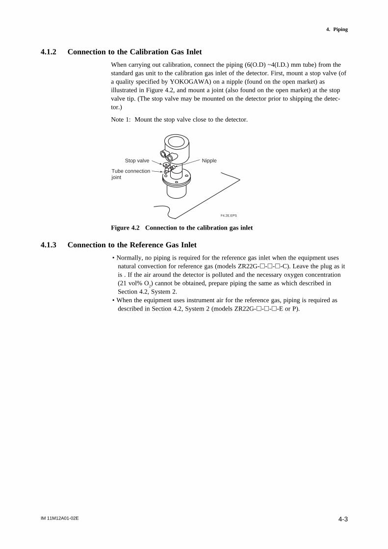
IM 11M12A01-02E 4-3
4. Piping
4.1.2 Connection to the Calibration Gas Inlet
When carrying out calibration, connect the piping (6(O.D) ~4(I.D.) mm tube) from thestandard gas unit to the calibration gas inlet of the detector. First, mount a stop valve (ofa quality specified by YOKOGAWA) on a nipple (found on the open market) asillustrated in Figure 4.2, and mount a joint (also found on the open market) at the stopvalve tip. (The stop valve may be mounted on the detector prior to shipping the detec-tor.)
Note 1: Mount the stop valve close to the detector.
F4.2E.EPS
NippleStop valve
Tube connection joint
Figure 4.2 Connection to the calibration gas inlet
4.1.3 Connection to the Reference Gas Inlet
• Normally, no piping is required for the reference gas inlet when the equipment usesnatural convection for reference gas (models ZR22G-h-h-h-C). Leave the plug as itis . If the air around the detector is polluted and the necessary oxygen concentration(21 vol% O
2) cannot be obtained, prepare piping the same as which described in
Section 4.2, System 2.• When the equipment uses instrument air for the reference gas, piping is required as
described in Section 4.2, System 2 (models ZR22G-h-h-h-E or P).
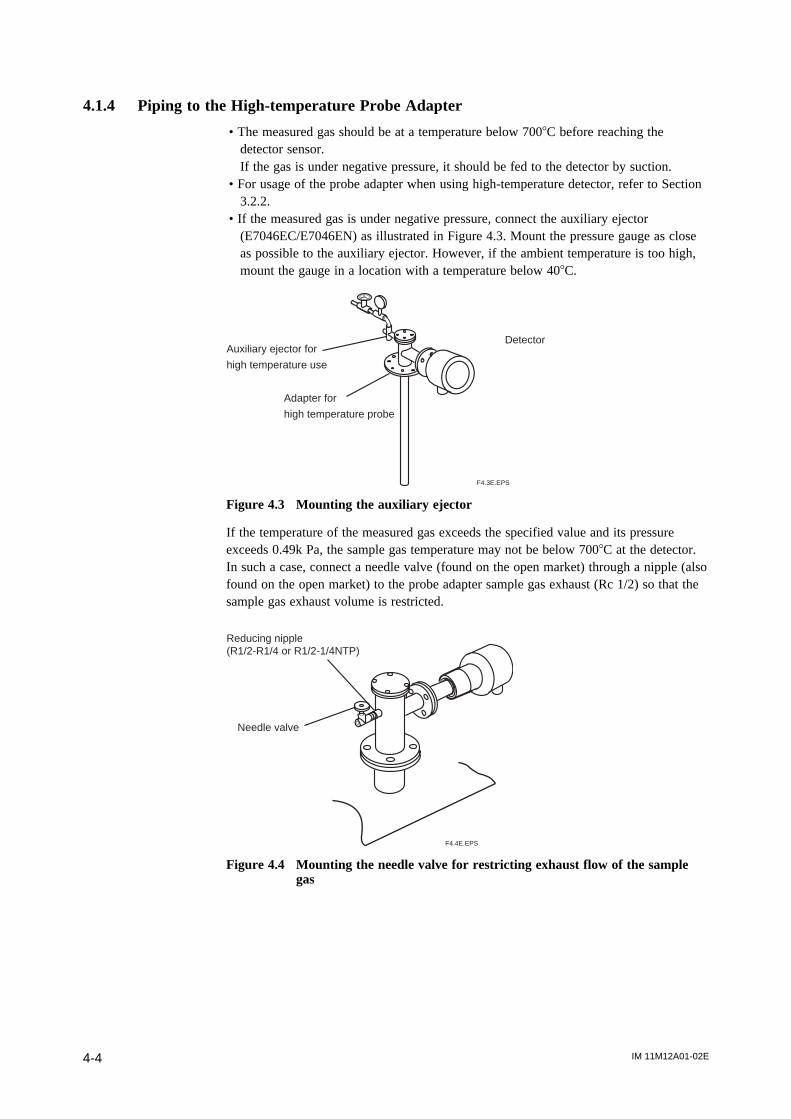
IM 11M12A01-02E4-4
4.1.4 Piping to the High-temperature Probe Adapter
• The measured gas should be at a temperature below 7008C before reaching thedetector sensor.If the gas is under negative pressure, it should be fed to the detector by suction.
• For usage of the probe adapter when using high-temperature detector, refer to Section3.2.2.
• If the measured gas is under negative pressure, connect the auxiliary ejector(E7046EC/E7046EN) as illustrated in Figure 4.3. Mount the pressure gauge as closeas possible to the auxiliary ejector. However, if the ambient temperature is too high,mount the gauge in a location with a temperature below 408C.
Auxiliary ejector for
high temperature use
Adapter for
high temperature probe
Detector
F4.3E.EPS
Figure 4.3 Mounting the auxiliary ejector
If the temperature of the measured gas exceeds the specified value and its pressureexceeds 0.49k Pa, the sample gas temperature may not be below 7008C at the detector.In such a case, connect a needle valve (found on the open market) through a nipple (alsofound on the open market) to the probe adapter sample gas exhaust (Rc 1/2) so that thesample gas exhaust volume is restricted.
Reducing nipple(R1/2-R1/4 or R1/2-1/4NTP)
Needle valve
F4.4E.EPS
Figure 4.4 Mounting the needle valve for restricting exhaust flow of the samplegas
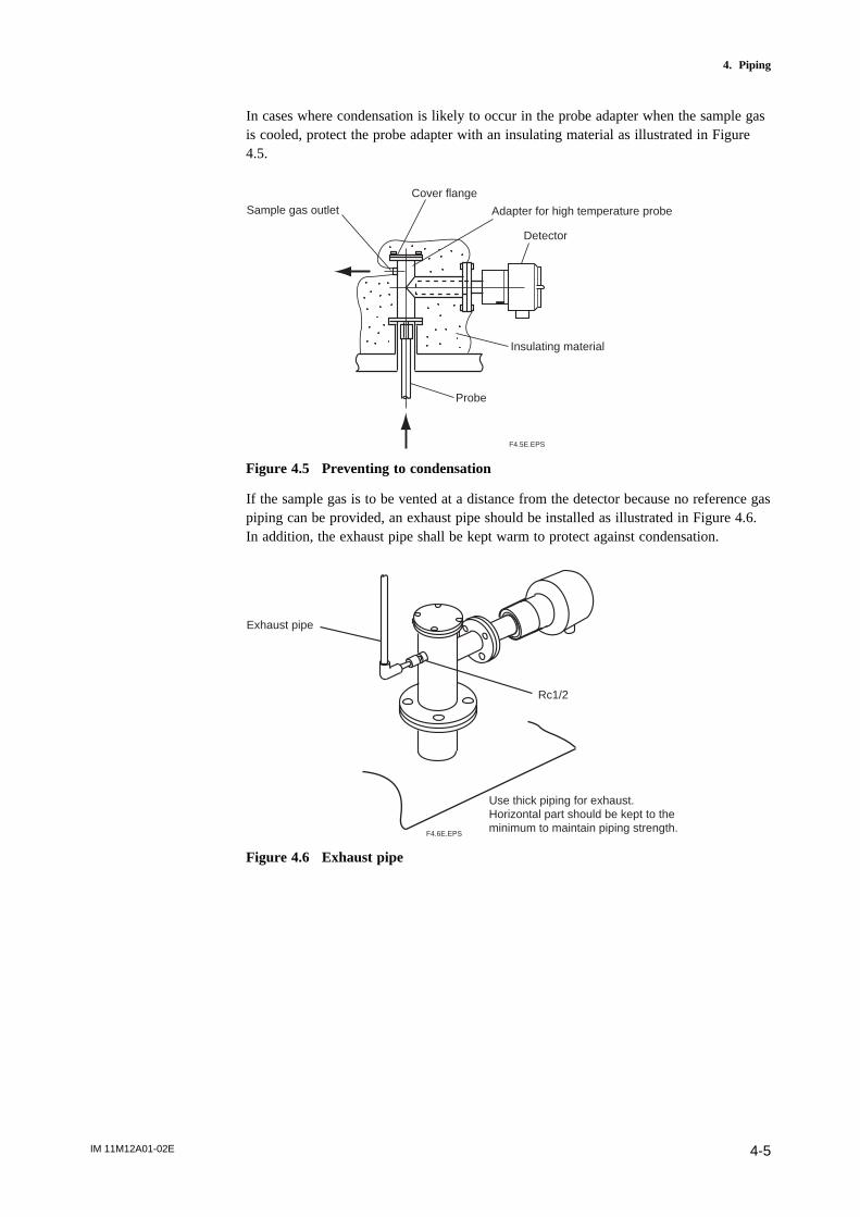
IM 11M12A01-02E 4-5
4. Piping
In cases where condensation is likely to occur in the probe adapter when the sample gasis cooled, protect the probe adapter with an insulating material as illustrated in Figure4.5.
Sample gas outlet
Cover flange
Adapter for high temperature probe
Detector
Insulating material
Probe
F4.5E.EPS
Figure 4.5 Preventing to condensation
If the sample gas is to be vented at a distance from the detector because no reference gaspiping can be provided, an exhaust pipe should be installed as illustrated in Figure 4.6.In addition, the exhaust pipe shall be kept warm to protect against condensation.
Exhaust pipe
Rc1/2
Use thick piping for exhaust.Horizontal part should be kept to the minimum to maintain piping strength.
F4.6E.EPS
Figure 4.6 Exhaust pipe
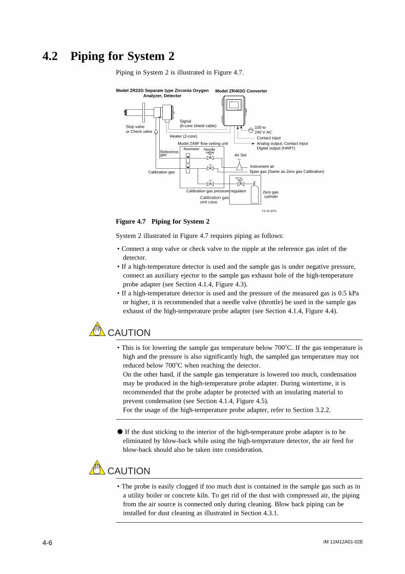
IM 11M12A01-02E4-6
4.2 Piping for System 2Piping in System 2 is illustrated in Figure 4.7.
~
Model ZA8F flow setting unit
EXA ZR402G
Model ZR22G Separate type Zirconia OxygenAnalyzer, Detector
Model ZR402G Converter
Reference gas
Calibration gas
Needle valve
flowmeter
Instrument air
Air Set
Calibration gas pressure regulator Zero gas cylinderCalibration gas
unit case
F4.7E.EPS
Stop valveor Check valve
Span gas (Same as Zero gas Calibration)
Signal(6-core shield cable)
Contact inputAnalog output, Contact inputDigital output (HART)
Heater (2-core)
100 to 240 V AC
Figure 4.7 Piping for System 2
System 2 illustrated in Figure 4.7 requires piping as follows:
• Connect a stop valve or check valve to the nipple at the reference gas inlet of thedetector.
• If a high-temperature detector is used and the sample gas is under negative pressure,connect an auxiliary ejector to the sample gas exhaust hole of the high-temperatureprobe adapter (see Section 4.1.4, Figure 4.3).
• If a high-temperature detector is used and the pressure of the measured gas is 0.5 kPaor higher, it is recommended that a needle valve (throttle) be used in the sample gasexhaust of the high-temperature probe adapter (see Section 4.1.4, Figure 4.4).
CAUTION
• This is for lowering the sample gas temperature below 7008C. If the gas temperature ishigh and the pressure is also significantly high, the sampled gas temperature may notreduced below 7008C when reaching the detector.On the other hand, if the sample gas temperature is lowered too much, condensationmay be produced in the high-temperature probe adapter. During wintertime, it isrecommended that the probe adapter be protected with an insulating material toprevent condensation (see Section 4.1.4, Figure 4.5).For the usage of the high-temperature probe adapter, refer to Section 3.2.2.
d If the dust sticking to the interior of the high-temperature probe adapter is to beeliminated by blow-back while using the high-temperature detector, the air feed forblow-back should also be taken into consideration.
• The probe is easily clogged if too much dust is contained in the sample gas such as ina utility boiler or concrete kiln. To get rid of the dust with compressed air, the pipingfrom the air source is connected only during cleaning. Blow back piping can beinstalled for dust cleaning as illustrated in Section 4.3.1.
CAUTION
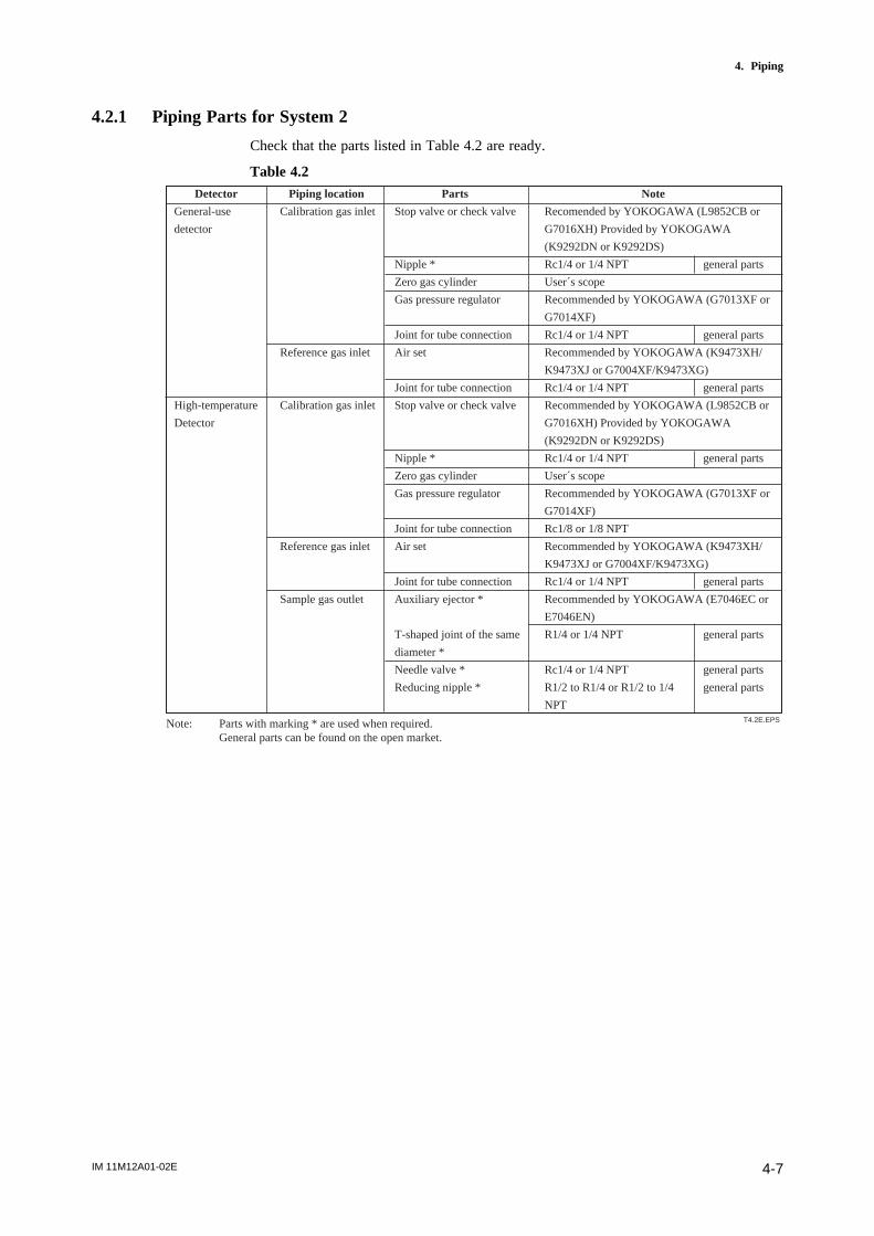
IM 11M12A01-02E 4-7
4. Piping
4.2.1 Piping Parts for System 2
Check that the parts listed in Table 4.2 are ready.
Table 4.2
Detector Piping location Parts Note
General-use Calibration gas inlet Stop valve or check valve Recomended by YOKOGAWA (L9852CB or
detector G7016XH) Provided by YOKOGAWA
(K9292DN or K9292DS)
Nipple * Rc1/4 or 1/4 NPT general parts
Zero gas cylinder User´s scope
Gas pressure regulator Recommended by YOKOGAWA (G7013XF or
G7014XF)
Joint for tube connection Rc1/4 or 1/4 NPT general parts
Reference gas inlet Air set Recommended by YOKOGAWA (K9473XH/
K9473XJ or G7004XF/K9473XG)
Joint for tube connection Rc1/4 or 1/4 NPT general parts
High-temperature Calibration gas inlet Stop valve or check valve Recommended by YOKOGAWA (L9852CB or
Detector G7016XH) Provided by YOKOGAWA
(K9292DN or K9292DS)
Nipple * Rc1/4 or 1/4 NPT general parts
Zero gas cylinder User´s scope
Gas pressure regulator Recommended by YOKOGAWA (G7013XF or
G7014XF)
Joint for tube connection Rc1/8 or 1/8 NPT
Reference gas inlet Air set Recommended by YOKOGAWA (K9473XH/
K9473XJ or G7004XF/K9473XG)
Joint for tube connection Rc1/4 or 1/4 NPT general parts
Sample gas outlet Auxiliary ejector * Recommended by YOKOGAWA (E7046EC or
E7046EN)
T-shaped joint of the same R1/4 or 1/4 NPT general parts
diameter *
Needle valve * Rc1/4 or 1/4 NPT general parts
Reducing nipple * R1/2 to R1/4 or R1/2 to 1/4 general parts
NPT
Note: Parts with marking * are used when required.General parts can be found on the open market.
T4.2E.EPS
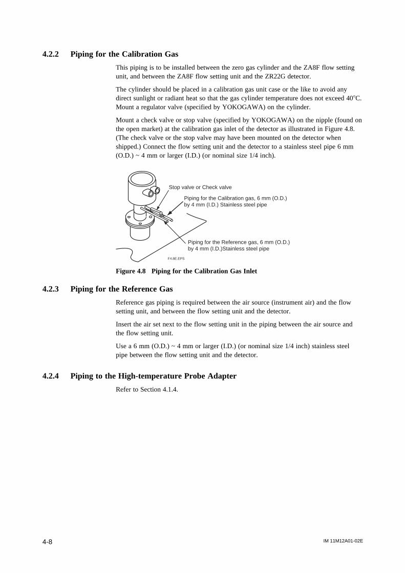
IM 11M12A01-02E4-8
4.2.2 Piping for the Calibration Gas
This piping is to be installed between the zero gas cylinder and the ZA8F flow settingunit, and between the ZA8F flow setting unit and the ZR22G detector.
The cylinder should be placed in a calibration gas unit case or the like to avoid anydirect sunlight or radiant heat so that the gas cylinder temperature does not exceed 408C.Mount a regulator valve (specified by YOKOGAWA) on the cylinder.
Mount a check valve or stop valve (specified by YOKOGAWA) on the nipple (found onthe open market) at the calibration gas inlet of the detector as illustrated in Figure 4.8.(The check valve or the stop valve may have been mounted on the detector whenshipped.) Connect the flow setting unit and the detector to a stainless steel pipe 6 mm(O.D.) ~ 4 mm or larger (I.D.) (or nominal size 1/4 inch).
F4.8E.EPS
Stop valve or Check valve
Piping for the Calibration gas, 6 mm (O.D.) by 4 mm (I.D.) Stainless steel pipe
Piping for the Reference gas, 6 mm (O.D.) by 4 mm (I.D.)Stainless steel pipe
Figure 4.8 Piping for the Calibration Gas Inlet
4.2.3 Piping for the Reference Gas
Reference gas piping is required between the air source (instrument air) and the flowsetting unit, and between the flow setting unit and the detector.
Insert the air set next to the flow setting unit in the piping between the air source andthe flow setting unit.
Use a 6 mm (O.D.) ~ 4 mm or larger (I.D.) (or nominal size 1/4 inch) stainless steelpipe between the flow setting unit and the detector.
4.2.4 Piping to the High-temperature Probe Adapter
Refer to Section 4.1.4.
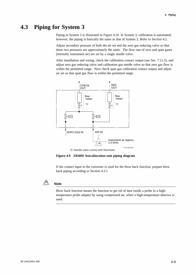
IM 11M12A01-02E 4-9
4. Piping
4.3 Piping for System 3Piping in System 3 is illustrated in Figure 4.10. In System 3, calibration is automated;however, the piping is basically the same as that of System 2. Refer to Section 4.2.
Adjust secondary pressure of both the air set and the zero gas reducing valve so thatthese two pressures are approximately the same. The flow rate of zero and span gases(normally instrument air) are set by a single needle valve.
After installation and wiring, check the calibration contact output (see Sec. 7.11.2), andadjust zero gas reducing valve and calibration gas needle valve so that zero gas flow iswithin the permitted range. Next check span gas calibration contact output and adjustair set so that span gas flow is within the permitted range.
CHECKOUT
ZERO GAS IN AIR IN
Instrument air Approx.1.5 l/min.
flow meter
flow meter
REFOUT
*2 *2
EV1 EV2
F2.6-3E.EPS
*2: Needle valve comes with flowmeter
Figure 4.9 ZR40H Autcalinration unit piping diagram
If the contact input to the converter is used for the blow back function, prepare blowback piping according to Section 4.3.1.
Note
Blow back function means the function to get rid of dust inside a probe in a high-temperature probe adapter by using compressed air, when a high-temperature detector isused.
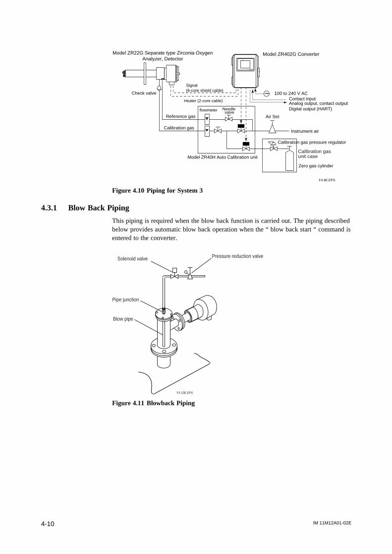
IM 11M12A01-02E4-10
Instrument air
Calibration gas pressure regulator
Air Set
Needle valveflowmeter
Reference gas
Calibration gas
Check valve ~
Zero gas cylinder
Model ZR40H Auto Calibration unit
Model ZR22G Separate type Zirconia OxygenAnalyzer, Detector
Model ZR402G Converter
Calibration gasunit case
F4.9E.EPS
EXA ZR402G
100 to 240 V ACContact inputAnalog output, contact outputDigital output (HART)
Signal (6-core shield cable)
Heater (2-core cable)
Figure 4.10 Piping for System 3
4.3.1 Blow Back Piping
This piping is required when the blow back function is carried out. The piping describedbelow provides automatic blow back operation when the “ blow back start “ command isentered to the converter.
Solenoid valve
Pipe junction
Blow pipe
F4.10E.EPS
Pressure reduction valve
Figure 4.11 Blowback Piping
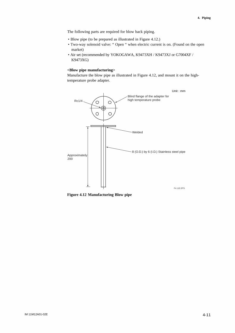
IM 11M12A01-02E 4-11
4. Piping
The following parts are required for blow back piping.
• Blow pipe (to be prepared as illustrated in Figure 4.12.)• Two-way solenoid valve: “ Open “ when electric current is on. (Found on the open
market)• Air set (recommended by YOKOGAWA, K9473XH / K9473XJ or G7004XF /
K9473XG)
<Blow pipe manufacturing>Manufacture the blow pipe as illustrated in Figure 4.12, and mount it on the high-temperature probe adapter.
Approximately 200
Rc1/4
Blind flange of the adapter for high temperature probe
Welded
8 (O.D.) by 6 (I.D.) Stainless steel pipe
F4.11E.EPS
Unit : mm
Figure 4.12 Manufacturing Blow pipe
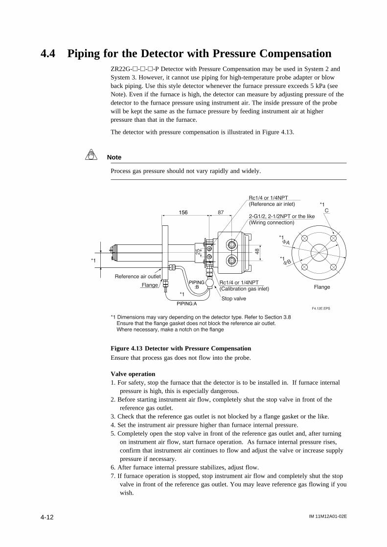
IM 11M12A01-02E4-12
4.4 Piping for the Detector with Pressure CompensationZR22G-h-h-h-P Detector with Pressure Compensation may be used in System 2 andSystem 3. However, it cannot use piping for high-temperature probe adapter or blowback piping. Use this style detector whenever the furnace pressure exceeds 5 kPa (seeNote). Even if the furnace is high, the detector can measure by adjusting pressure of thedetector to the furnace pressure using instrument air. The inside pressure of the probewill be kept the same as the furnace pressure by feeding instrument air at higherpressure than that in the furnace.
The detector with pressure compensation is illustrated in Figure 4.13.
Note
Process gas pressure should not vary rapidly and widely.
25
48
156 87
BF
AF
C
Rc1/4 or 1/4NPT
(Reference air inlet)
2-G1/2, 2-1/2NPT or the like
(Wiring connection)
FlangeFlange
PIPING:A
Reference air outletPIPING
:B
Stop valve*1
*1
*1
*1
*1
*1 Dimensions may vary depending on the detector type. Refer to Section 3.8
Ensure that the flange gasket does not block the reference air outlet.
Where necessary, make a notch on the flange
Rc1/4 or 1/4NPT
(Calibration gas inlet)
F4.12E.EPS
Figure 4.13 Detector with Pressure CompensationEnsure that process gas does not flow into the probe.
Valve operation1. For safety, stop the furnace that the detector is to be installed in. If furnace internal
pressure is high, this is especially dangerous.2. Before starting instrument air flow, completely shut the stop valve in front of the
reference gas outlet.3. Check that the reference gas outlet is not blocked by a flange gasket or the like.4. Set the instrument air pressure higher than furnace internal pressure.5. Completely open the stop valve in front of the reference gas outlet and, after turning
on instrument air flow, start furnace operation. As furnace internal pressure rises,confirm that instrument air continues to flow and adjust the valve or increase supplypressure if necessary.
6. After furnace internal pressure stabilizes, adjust flow.7. If furnace operation is stopped, stop instrument air flow and completely shut the stop
valve in front of the reference gas outlet. You may leave reference gas flowing if youwish.
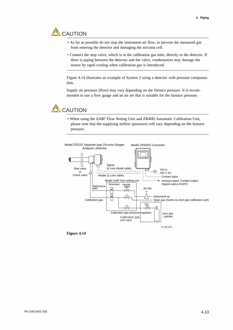
IM 11M12A01-02E 4-13
4. Piping
CAUTION
• As far as possible do not stop the instrument air flow, to prevent the measured gasfrom entering the detector and damaging the zirconia cell.
• Connect the stop valve, which is at the calibration gas inlet, directly to the detector. Ifthere is piping between the detector and the valve, condensation may damage thesensor by rapid cooling when calibration gas is introduced.
Figure 4.14 illustrates an example of System 2 using a detector with pressure compensa-tion.
Supply air pressure (flow) may vary depending on the furnace pressure. It is recom-mended to use a flow gauge and an air set that is suitable for the furnace pressure.
CAUTION
• When using the ZA8F Flow Setting Unit and ZR40H Automatic Calibration Unit,please note that the supplying airflow (pressure) will vary depending on the furnacepressure.
~
Model ZA8F flow setting unit
EXA ZR402G
Model ZR22G Separate type Zirconia OxygenAnalyzer, Detector
Model ZR402G Converter
Reference gas
Calibration gas
Stop valveor
Check valve
Needle valve
flowmeter
Instrument air
Air Set
Calibration gas pressure regulator Zero gas cylinderCalibration gas
unit case
F4.13E.EPS
Span gas (Same as Zero gas calibration unit)
100 to 240 V AC
Contact input
Analog output, Contact outputDigital output (HART)
Signal(6 core shield cable)
Heater (2 core cable)
Figure 4.14

IM 11M12A01-02E4-14
4.4.1 Piping Parts for a System using Detector with Pressure Compensation
Check that the parts listed in Table 4.3 are ready.
Table 4.3
Detector Piping location Parts Note
Detector with Calibration gas inlet Stop valve or check valve Recommended by YOKOGAWA (L9852CB or
G7016XH)Provided by YOKOGAWA (K9292DN
pressure or K9292DS)
compensation Nipple * Rc1/4 or 1/4 NPT general parts
Zero gas cylinder User´s scope
Gas pressure regulator of a quality specified by YOKOGAWA (G7013XF
or G7014XF)
Joint for tube connection Rc1/4 or 1/4 NPT general parts
Reference gas inlet Air set of a quality specified by YOKOGAWA (K9473XH
/ K9473XJ or G7004XF / K9473XG)
Joint for tube connection Rc1/4 or 1/4 NPT general parts
Note: Parts with marking * are used when required.General parts can be found on the open market.
T4.3E.EPS
4.4.2 Piping for the Calibration Gas
Calibration gas piping is basically identical to that of System 2. See Section 4.2.2.
4.4.3 Piping for the Reference Gas
Reference gas piping is basically identical to that of for System 2. See Section 4.2.3.

IM 11M12A01-02E 5-1
5. Wiring
5. Wiring
In this Chapter, the wiring necessary for connection to the EXAxtZR Separate-typeZirconia Oxygen Analyzer is described.
5.1 General
CAUTION
• NEVER supply current to the converter or any other device constituting a powercircuit in combination with the converter, until all wiring is completed.
• This product complies with CE marking.Where compliance with CE marking is necessary, the following wiring procedure isnecessary.
1. Install an external switch or circuit breaker to the power supply of the converter.2. Use an external switch or circuit breaker rated 5A and conforming with IEC 947-1 or
IEC 947-3.3. It is recommended that the external switch or circuit breaker be mounted in the same
room as the converter.4. The external switch or circuit breaker should be installed within the reach of the
operator, and marked as the power supply switch of this equipment.
Wiring procedure
Wiring should be performed according to the following procedure:
1. Be sure to connect the shield line to FG terminal of the converter.2. The outer sheath of the signal line should be stripped to a length of 50 mm or less.
The most outer sheath of the power cable should be stripped to a length of 20 mm orless.
3. Signals may be affected by noise if signal lines, power cable and heater cable arelocated in the same conduit. When using conduit, signal lines should be installed in aseparate conduit than power and heater cables.
4. Install metal blind plug(s) in unused cable connection gland(s) of the converter.5. Metal conduit should be grounded.6. The following cables are used for wiring:
Table 5.1 Cable specifications
T5.1E.EPS
Terminal name of converter Name Need for shields Cable type Number of wires
CELL+, CELL-
HTR TC+, HTR TC-
CJ+, CJ-
HEATER
L, N,
AO-1+, AO-1-, AO-2+, AO-2-
DO-1, DO-2, DO-3, DO-4
AC-Z, AC-S, AC-C
DI-1, DI-2, DI-C
Converter signal
Converter heater
Power supply
Analog output
Contact output
Automatic
Calibration unit
Contact input
s
s
CVVS
CVV
CVV
CVVS
CVV
CVV
CVV
6
2
2 or 3 *
2 or 4
2 to 8
3
3
Note *: When the case is used for protective grounding, use a 2-wire cable.

IM 11M12A01-02E5-2
CAUTION
• Select suitable cable O.D. to match the cable gland size.• Protective grounding should be connected in ways equivalent to JIS D style (Class 3)
grounding (the grounding resistance is 100 V or less).• Special consideration of cable length should be taken for the HART communication,
For the detail, refer to Section 1.1.2 of the IM 11M12A01-51E " Communication LineRequirement ".
5.1.1 Terminals for the External Wiring in the Converter
Open the front door and remove the terminal covering plate to gain access to theconverter external wiring terminals (see Figure 5.2).
CAUTION
After wiring necessary cable to the converter terminals, be sure to fix the terminalcovering plate with two screws again.
F5.2E.EPS
Front door
Cable inlet
Terminals are visible when the terminal cover is removed.
Figure 5.2 Terminals for external wiring in the converter
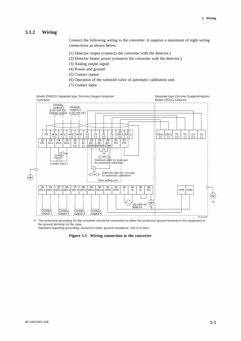
IM 11M12A01-02E 5-3
5. Wiring
5.1.2 Wiring
Connect the following wiring to the converter. It requires a maximum of eight wiringconnections as shown below.
(1) Detector output (connects the converter with the detector.)(2) Detector heater power (connects the converter with the detector.)(3) Analog output signal(4) Power and ground(5) Contact output(6) Operation of the solenoid valve of automatic calibration unit(7) Contact input
1FG
2AO1(+)
3AO1(-)
4AO2(+)
5AO2(-)
6CJ(+)
7CJ(-)
8TC(+)
9TC(-)
10CELL
(+)
11CELL
(-)12FG
13DI-1
14DI-2
15DI-C
16AI(+)
17AI(-)
18AC-
ZERO
19AC-
SPAN
20AC-
COM
21FG
22FG
CELL(+)
CELL(-)
TC(+)
TC(-)
CJ(+)
CJ(-)
23DO-1
24DO-1
25DO-2
26DO-2
27DO-3
28DO-3
29DO-4
30DO-4
31HTR
32HTR
33L
34N
35G
36FG HTR HTR
100-240V AC50/60 Hz
F5.3E.EPS
Model ZR402G Separate type Zirconia Oxygen Analyzer/ Converter
Separate type Zirconia OxygenAnalyzer, Model ZR22G Detector
Analog output 2
Analog output 1
4-20 mA DC4-20 mA DCDigital output
Contact input 2
Contact input 1
Contact output 1
Contact output 2
Contact output 3
Contact output 4
Solenoid valve for span gas for automatic calibration
Solenoid valve for zero gas for automatic calibration
Flow setting unit
*1
*1
The protective grounding for the converter should be connected to either the protective ground terminal in the equipment or the ground terminal on the case.Standard regarding grounding: Ground to earth, ground resistance: 100 V or less.
*1
Figure 5.3 Wiring connection to the converter
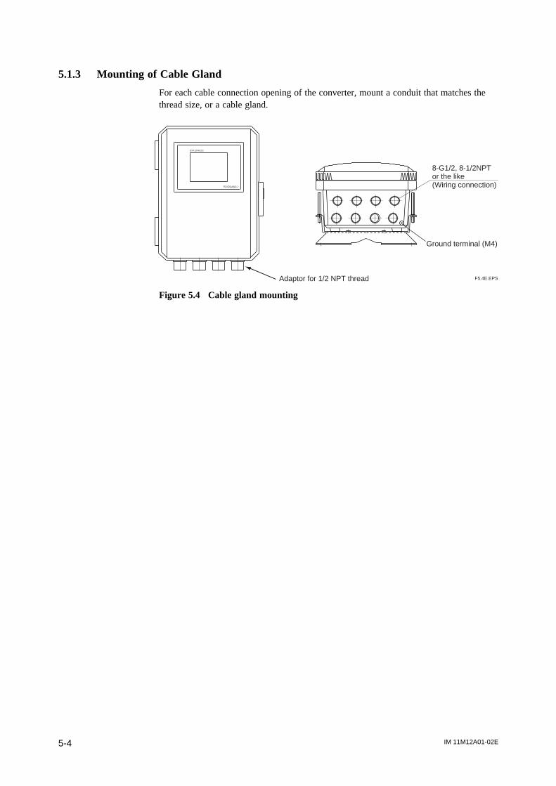
IM 11M12A01-02E5-4
5.1.3 Mounting of Cable Gland
For each cable connection opening of the converter, mount a conduit that matches thethread size, or a cable gland.
EXA ZR402G
Ground terminal (M4)
Adaptor for 1/2 NPT thread F5.4E.EPS
8-G1/2, 8-1/2NPT or the like (Wiring connection)
Figure 5.4 Cable gland mounting

IM 11M12A01-02E 5-5
5. Wiring
5.2 Wiring for Detector OutputThis wiring enables the converter to receive cell output from the detector, output from athermocouple and a reference junction compensation signal. Install wires that allow for10V of loop resistance or less. Keep detector wiring away from power wiring.
Separate signal and power wiring.
CELL(+)CELL(+)CELL(-)CELL(-)TC(+)TC(+)
TC(-)TC(-)
CJ(+)CJ(+)
CJ(-)CJ(-)
FGShielded cables
Shielded cables
Detector Converter
CELL(+)CELL(+)
CELL(-)CELL(-)
TC(+)TC(+)
TC(-)TC(-)
CJ(+)CJ(+)
CJ(-)CJ(-)
FG
Detector Converter
(2) Ambient temperature of the detector: exceeding 808C
Heat-resistant wiring
Terminal box
(1) Ambient temperature of the detector: 808C or less
F5.5E.EPS
Figure 5.5 Wiring for detector output
Note
If shielded cables cannot be used between the detector and the terminal box, for
example, when heat-resistant wiring is used, locate the detector and the terminal box
as close together as possible.
5.2.1 Cable Specifications
Basically, PVC sheathed PVC insulated cable (six core) is used for this wiring. Whenthe ambient temperature of the detector exceeds 808C, install a terminal box, andconnect with the detector using six-piece 600-V silicon rubber insulated glass braidedwire.

IM 11M12A01-02E5-6
5.2.2 Connection to the Detector
To connect cables to the detector, proceed as follows:
(1) Mount conduits of the specified thread size or cable glands to the wiring connectionsof the detector.The detector may need to be removed in future for maintenance, so be sure to allowsufficient cable length.
(2) If the ambient temperature at the location of wire installation is 80 to 1508C, be sureto use a flexible metallic wire conduit. If a non-shielded “ 600V silicon rubberinsulated glass braided wire “ is used, keep the wire away from noise sources toavoid noise interference.
(3) Figure 5.6 shows the layout of the detector terminals.
CELL 1
TC 1(with Si TUBE)
TC 2
TCCELL CJ1 2 3 4 5 6
87H T R
CELL(+)
CELL(-)
TC(+)
TC(-)
CJ(+)
CJ(-)
HTR HTR
F5.6E.EPS
To converter, or terminal box
To groundTo converter, orterminal box
Figure 5.6 Detector terminals
The sizes of the terminal screw threads are M3.5 except for the M4 on groundingterminal. Each wire in the cable should be terminated in the corresponding size of crimpterminal (*1) respectively.
*1: If the ambient temperature at the detector installation site exceeds 608C, use a “ bare crimp-on terminal”.
(4) Except when “600V silicon rubber insulated glass braided wire” is used, connect thecable shield to the FG terminal of the converter.
IM 11M12A01-02E 5-7
5. Wiring
5.2.3 Connection to the Converter
To connect the wiring to the converter, proceed as follows:
(1) M4 screws are used for the terminals of the converter. Each wire in the cable shouldbe terminated in the corresponding size crimp-on terminal.
(2) When a rubber insulated glass braided wire is used for wiring to the detector, use aterminal box. For wiring between the terminal box and the converter, basically usecable, e.g. PVC sheathed PVC insulated cable, rather than individual wires.
Note
The above is to prevent moisture or corrosive gas from entering the converter and toground the detector without fail.
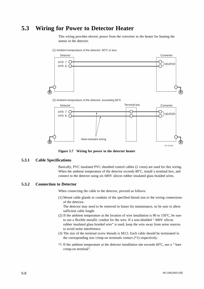
IM 11M12A01-02E5-8
5.3 Wiring for Power to Detector HeaterThis wiring provides electric power from the converter to the heater for heating thesensor in the detector.
Detector Converter
(1) Ambient temperature of the detector: 808C or less
(2) Ambient temperature of the detector: exceeding 808C
Heat-resistant wiring
HTR 7HTR 8
HTR 7HTR 8
HEATER
HEATER
Terminal box
F5.7E.EPS
Detector Converter
Figure 5.7 Wiring for power to the detector heater
5.3.1 Cable Specifications
Basically, PVC insulated PVC sheathed control cables (2 cores) are used for this wiring.When the ambient temperature of the detector exceeds 808C, install a terminal box, andconnect to the detector using six 600V silicon rubber insulated glass braided wires.
5.3.2 Connection to Detector
When connecting the cable to the detector, proceed as follows:
(1) Mount cable glands or conduits of the specified thread size to the wiring connectionsof the detector.The detector may need to be removed in future for maintenance, so be sure to allowsufficient cable length.
(2) If the ambient temperature at the location of wire installation is 80 to 1508C, be sureto use a flexible metallic conduit for the wire. If a non-shielded “ 600V siliconrubber insulated glass braided wire” is used, keep the wire away from noise sourcesto avoid noise interference.
(3) The size of the terminal screw threads is M3.5. Each cable should be terminated inthe corresponding size crimp-on terminals contact (*1) respectively.
*1 If the ambient temperature at the detector installation site exceeds 608C, use a “ barecrimp-on terminal”.
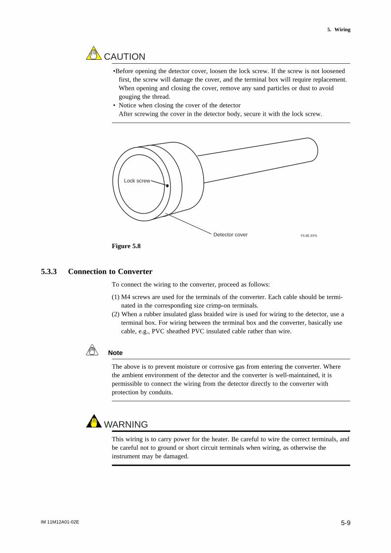
IM 11M12A01-02E 5-9
5. Wiring
CAUTION
•Before opening the detector cover, loosen the lock screw. If the screw is not loosenedfirst, the screw will damage the cover, and the terminal box will require replacement.When opening and closing the cover, remove any sand particles or dust to avoidgouging the thread.
• Notice when closing the cover of the detectorAfter screwing the cover in the detector body, secure it with the lock screw.
Lock screw
Detector cover F5.8E.EPS
Figure 5.8
5.3.3 Connection to Converter
To connect the wiring to the converter, proceed as follows:
(1) M4 screws are used for the terminals of the converter. Each cable should be termi-nated in the corresponding size crimp-on terminals.
(2) When a rubber insulated glass braided wire is used for wiring to the detector, use aterminal box. For wiring between the terminal box and the converter, basically usecable, e.g., PVC sheathed PVC insulated cable rather than wire.
Note
The above is to prevent moisture or corrosive gas from entering the converter. Wherethe ambient environment of the detector and the converter is well-maintained, it ispermissible to connect the wiring from the detector directly to the converter withprotection by conduits.
WARNING
This wiring is to carry power for the heater. Be careful to wire the correct terminals, andbe careful not to ground or short circuit terminals when wiring, as otherwise theinstrument may be damaged.

IM 11M12A01-02E5-10
5.4 Wiring for Analog OutputThis wiring is for transmitting 4 to 20 mA DC output signals to a device, e.g. recorder.Maintain the load resistance including the wiring resistance at 550V or less.
Shielded cable
Receiver 1
Receiver 2
Converter
1
2
1
2
AO1(+)
AO1(-)
AO2(+)
AO2(-)
FG
F5.9E.EPS
Figure 5.9 Wiring for analog output
5.4.1 Cable Specifications
For this wiring, use a 2-core or a 4-core shielded cable.
5.4.2 Wiring Procedure
(1) M4 screws are used for the terminal of the converter. Each wire of the cable shouldbe terminated corresponding crimp-on terminals. Ensure that the cable shield isconnected to the FG terminal of the converter.
(2) Be sure to connect “+” and “-” polarities correctly.
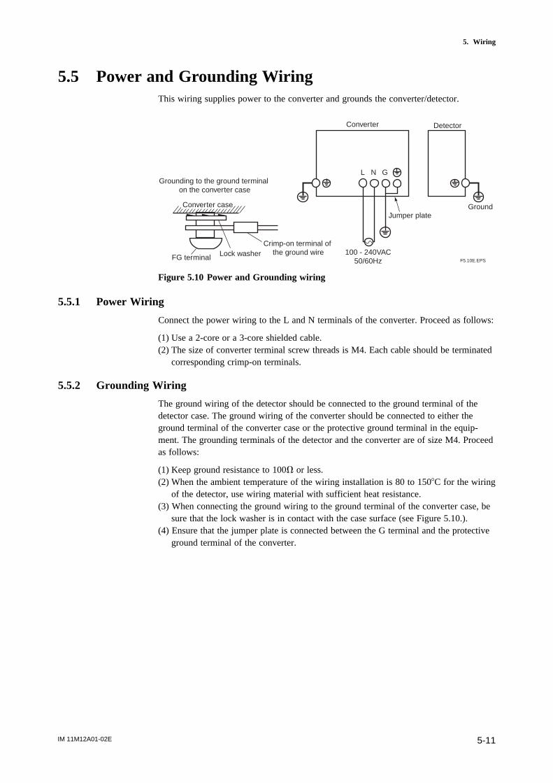
IM 11M12A01-02E 5-11
5. Wiring
5.5 Power and Grounding WiringThis wiring supplies power to the converter and grounds the converter/detector.
Converter
Jumper plate
L N G
Detector
Ground
100 - 240VAC50/60Hz
Grounding to the ground terminal on the converter case
Converter case
FG terminal Lock washerCrimp-on terminal of
the ground wireF5.10E.EPS
Figure 5.10 Power and Grounding wiring
5.5.1 Power Wiring
Connect the power wiring to the L and N terminals of the converter. Proceed as follows:
(1) Use a 2-core or a 3-core shielded cable.(2) The size of converter terminal screw threads is M4. Each cable should be terminated
corresponding crimp-on terminals.
5.5.2 Grounding Wiring
The ground wiring of the detector should be connected to the ground terminal of thedetector case. The ground wiring of the converter should be connected to either theground terminal of the converter case or the protective ground terminal in the equip-ment. The grounding terminals of the detector and the converter are of size M4. Proceedas follows:
(1) Keep ground resistance to 100V or less.(2) When the ambient temperature of the wiring installation is 80 to 1508C for the wiring
of the detector, use wiring material with sufficient heat resistance.(3) When connecting the ground wiring to the ground terminal of the converter case, be
sure that the lock washer is in contact with the case surface (see Figure 5.10.).(4) Ensure that the jumper plate is connected between the G terminal and the protective
ground terminal of the converter.

IM 11M12A01-02E5-12
5.6 Contact Output WiringContact outputs 1 to 3 can be freely assigned to "low limit alarm", "high limit alarm",etc. user selectable, but the assignment of contact output 4 is fixed ("error output"). Andthe action (contact closed on error output) also cannot be changed.
When using these contact outputs, install the wiring as follows:
#1 Output
#2 Output
#3 Output
#4 Output
DO-1
DO-1
DO-2
DO-2
DO-3
DO-3
Terminal box Annunciator or the like
F5.11E.EPS
Converter
DO-4
DO-4
Figure 5.11 Contact output wiring
5.6.1 Cable Specifications
Number of wire in cable varies depending on the number of contact used.
5.6.2 Wiring Procedure
(1) M4 screws are used for the terminals of the converter. Each wire in the cable shouldbe terminated in the corresponding crimp-on terminal.
(2) The capacities of the contact output relay are 30 V DC 3 A, 250 V AC 3 A. Connecta load (e.g. pilot lamp and annunciator) within these limits.

IM 11M12A01-02E 5-13
5. Wiring
5.7 Wiring for ZR40H Automatic Calibration UnitThis wiring is for operating the solenoid valve for the zero gas and the span gas in theZR40H Automatic Calibration Unit, in a system where the calibration gas flow rate isautomatically controlled (e.g. System configuration 3). When installing this wiring,proceed as follows:
COMMON SPAN ZERO
to ZR402G terminal "AC-COM"
to ZR402G terminal "AC-SPAN"
to ZR402G terminal "AC-ZERO"
Wiring inlet2-G1/2, Pg13.5, M20 or 1/2NPT
ZEROSPAN
COMMON
Span gas solenoid valve
Zero gas solenoid valve
Terminal screw : M4
Wire or equivalent
F5.12E.EPS
Figure 5.12 Automatic Calibration Unit
5.7.1 Cable Specifications
Use a three-core cable for this wiring.
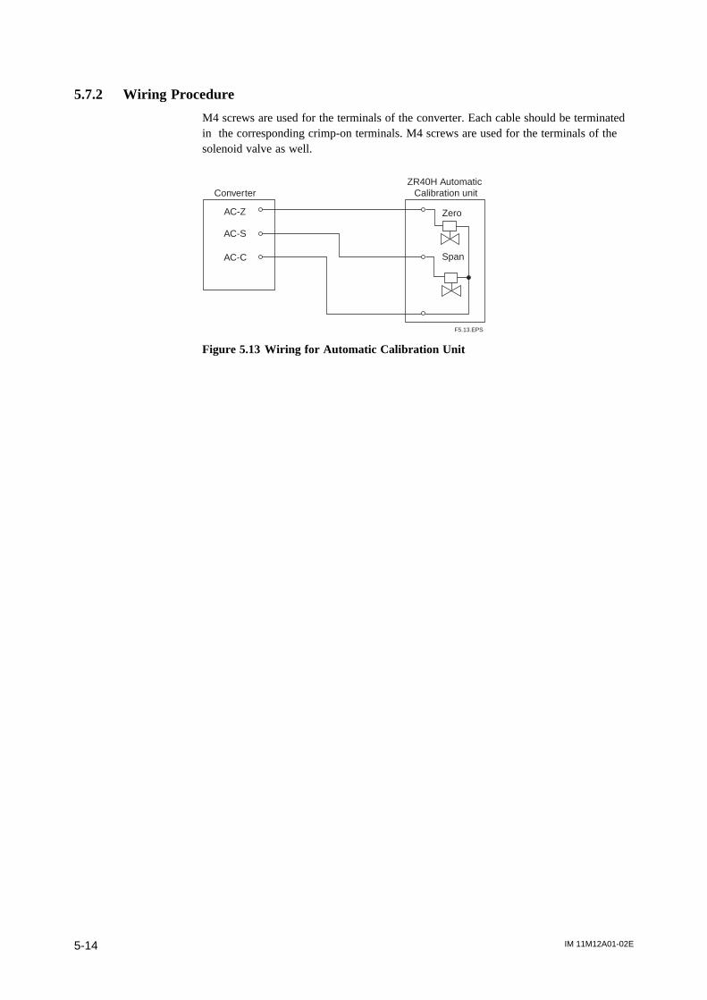
IM 11M12A01-02E5-14
5.7.2 Wiring Procedure
M4 screws are used for the terminals of the converter. Each cable should be terminatedin the corresponding crimp-on terminals. M4 screws are used for the terminals of thesolenoid valve as well.
ConverterZR40H Automatic
Calibration unit
AC-Z
AC-C
AC-S
Zero
Span
F5.13.EPS
Figure 5.13 Wiring for Automatic Calibration Unit
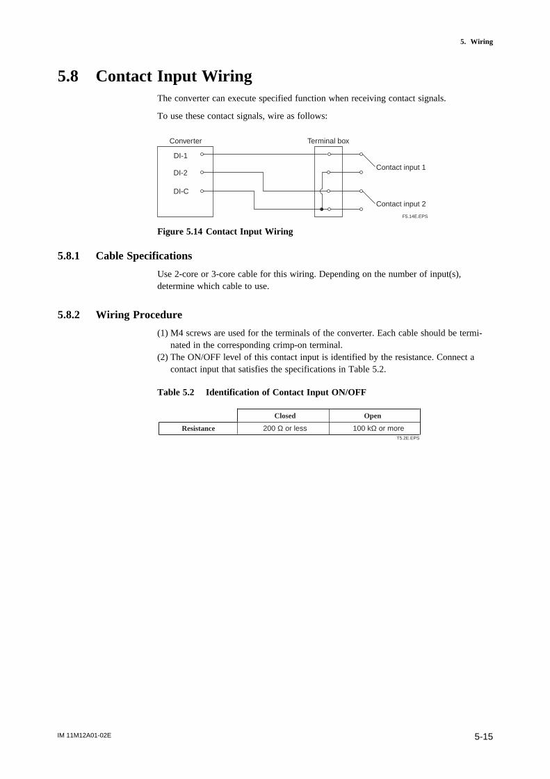
IM 11M12A01-02E 5-15
5. Wiring
5.8 Contact Input WiringThe converter can execute specified function when receiving contact signals.
To use these contact signals, wire as follows:
Converter Terminal box
DI-1
DI-C
DI-2Contact input 1
Contact input 2
F5.14E.EPS
Figure 5.14 Contact Input Wiring
5.8.1 Cable Specifications
Use 2-core or 3-core cable for this wiring. Depending on the number of input(s),determine which cable to use.
5.8.2 Wiring Procedure
(1) M4 screws are used for the terminals of the converter. Each cable should be termi-nated in the corresponding crimp-on terminal.
(2) The ON/OFF level of this contact input is identified by the resistance. Connect acontact input that satisfies the specifications in Table 5.2.
Table 5.2 Identification of Contact Input ON/OFF
T5.2E.EPS
Closed Open
Resistance 200 Ω or less 100 kΩ or more

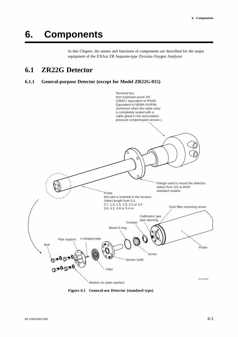
IM 11M12A01-02E 6-1
6. Components
6. Components
In this Chapter, the names and functions of components are described for the majorequipment of the EXAxt ZR Separate-type Zirconia Oxygen Analyzer.
6.1 ZR22G Detector
6.1.1 General-purpose Detector (except for Model ZR22G-015)
Probethis part is inserted in the furnace. Select length from 0.4, 0.7, 1.0, 1.5, 2.0, 2.5 or 3.03.6, 4.2, 4.8 or 5.4 m.
Flange used to mount the detector. Select from JIS or ANSI standard models.
F6.1E.EPS
Bolt
Washer (or plain washer)
Pipe support U-shaped pipe
Metal O-ring
Dust filter mounting screw
Sensor (cell)
Filter
Contact
Screw
Probe
Calibration gas pipe opening
Terminal box, Non explosion-proof JIS C0920 / equivalent to IP44D.Equivalent to NEMA 4X/IP66(Achieved when the cable entry is completely sealed with a cable gland in the recirculationpressure compensated version.)
Figure 6.1 General-use Detector (standard type)
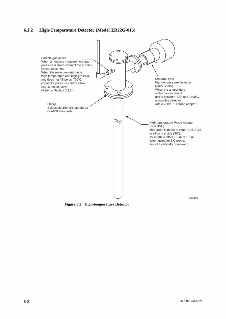
IM 11M12A01-02E6-2
6.1.2 High-Temperature Detector (Model ZR22G-015)
Sample gas outletWhen a negative measurement gas pressure is used, connect the auxiliary ejector assembly. When the measurement gas is high-temperature and high-pressure, and does not fall below 7008C, connect a pressure control valve (e.g. a needle valve).(Refer to Section 3.2.2.)
Separate type High-temperature Detector (ZR22G-015) When the temperature of the measurement gas is between 7008 and 14008C, mount this detector with a ZO21P-H probe adapter.
F6.2E.EPS
FlangeSelectable from JIS standards or ANSI standards
High-temperature Probe Adapter (ZO21P-H)The probe is made of either SUS 310S or silicon carbide (SiC). Its length is either 1.0 m or 1.5 m. When using an SiC probe, mount it vertically downward.
Figure 6.2 High-temperature Detector
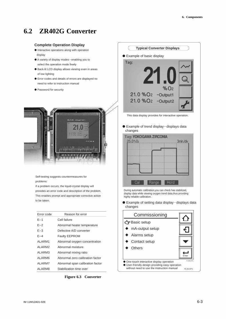
IM 11M12A01-02E 6-3
6. Components
6.2 ZR402G Converter
Enter
Commissioning
r mA-output setup
r Alarms setup
r Contact setup
r Others
Basic setup
F7.6E.EPS
Complete Operation Displayd Interactive operations along with operation
display
d A variety of display modes2enabling you to
select the operation mode freely
d Back-lit LCD display allows viewing even in areas
of low lighting
d Error codes and details of errors are displayed no
need to refer to instruction manual
d Password for security
This data display provides for interactive operation.
d Example of basic display
d Example of trend display2displays data changes
Error code Reason for error
E--1 Cell failure
E--2 Abnormal heater temperature
E--3 Defective A/D converter
E--4 Faulty EEPROM
ALARM1 Abnormal oxygen concentration
ALARM2 Abnormal moisture
ALARM3 Abnormal mixing ratio
ALARM6 Abnormal zero calibration factor
ALARM7 Abnormal span calibration factor
ALARM8 Stabilization time over
Typical Converter Displays
d Example of setting data display2displays data changes
During automatic calibration,you can check has stabilized, display data while viewing oxygen trend data,thus providing highly reliable calibration.
d One-touch interactive display operationd User-friendly design providing easy operation without need to use the instruction manual
Self-testing suggests countermeasures for
problems
If a problem occurs, the liquid-crystal display will
provides an error code and description of the problem.
This enables prompt and appropriate corrective action
to be taken.
F6.3E.EPS
Figure 6.3 Converter
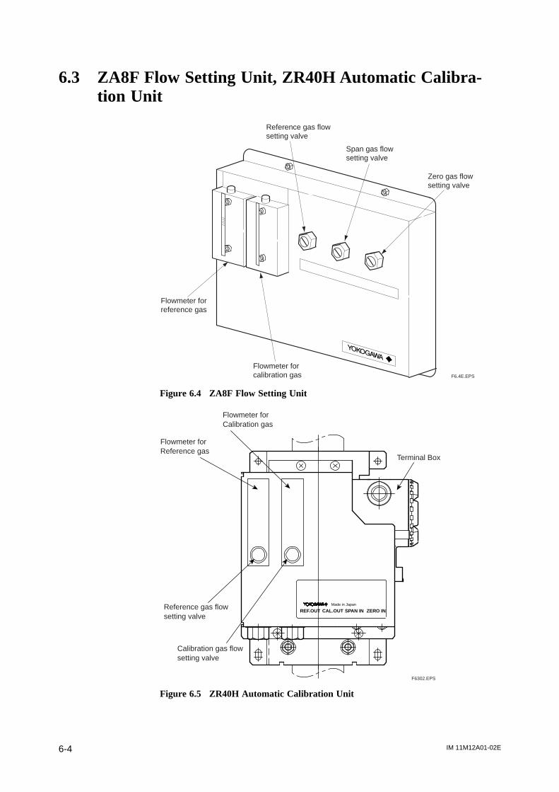
IM 11M12A01-02E6-4
6.3 ZA8F Flow Setting Unit, ZR40H Automatic Calibra-tion Unit
Reference gas flow setting valve
Span gas flow setting valve
Zero gas flow setting valve
Flowmeter forreference gas
Flowmeter forcalibration gas F6.4E.EPS
Figure 6.4 ZA8F Flow Setting Unit
CAL.OUTREF.OUTMade in Japan
ZERO INSPAN IN
F6302.EPS
Flowmeter for Calibration gas
Flowmeter for Reference gas
Terminal Box
Reference gas flowsetting valve
Calibration gas flowsetting valve
Figure 6.5 ZR40H Automatic Calibration Unit
IM 11M12A01-02E 7-1
7. Startup
7. Startup
The following describes the minimum operating requirements — from supplying powerto the converter to analog output confirmation to manual calibration.
System tuning by the HART communicator, refer to IM11M12A01-51E " HARTCommunication Protocol ".
7.1 Checking Piping and Wiring ConnectionsCheck that the piping and wiring connections have been properly completed in accor-dance with Chapter 4, “Piping,” and Chapter 5, “Wiring.”
7.2 Checking Valve SetupSet up valves and associated components used in the analyzer system as follows:
(1) If a stop valve is used in the detector’s calibration-gas inlet, fully close this valve.(2) If instrument air is used as the reference gas, adjust the air-set secondary pressure so
that an air pressure equals measured gas pressure plus approx. 50 kPa (or measuredgas pressure plus approx. 150 kPa when a check valve is used, maximum pressurerating is 300 kPa) is obtained. Turn the reference-gas flow setting valve in the flowsetting unit to obtain a flow of 800 to 1000 ml/min. (Turning the valve shaft counter-clockwise increases the rate of flow. Before turning the valve shaft, if the valve has alock nut, first loosen the lock nut.) After completing the valve setup, be sure totighten the lock nut.
Note
The calibration-gas flow setting is described later. Fully close the needle valve in theflow setting unit.
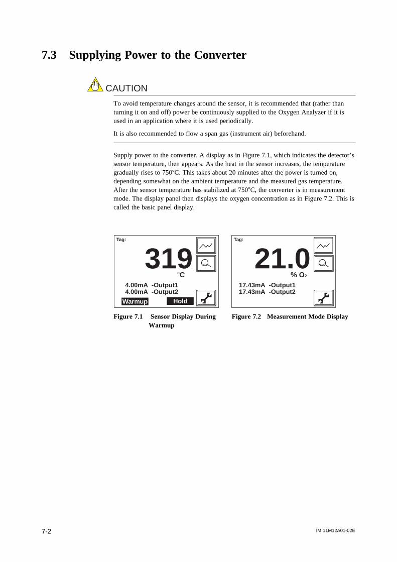
IM 11M12A01-02E7-2
7.3 Supplying Power to the Converter
CAUTION
To avoid temperature changes around the sensor, it is recommended that (rather thanturning it on and off) power be continuously supplied to the Oxygen Analyzer if it isused in an application where it is used periodically.
It is also recommended to flow a span gas (instrument air) beforehand.
Supply power to the converter. A display as in Figure 7.1, which indicates the detector’ssensor temperature, then appears. As the heat in the sensor increases, the temperaturegradually rises to 7508C. This takes about 20 minutes after the power is turned on,depending somewhat on the ambient temperature and the measured gas temperature.After the sensor temperature has stabilized at 7508C, the converter is in measurementmode. The display panel then displays the oxygen concentration as in Figure 7.2. This iscalled the basic panel display.
Warmup
Tag:
3198C
4.00mA -Output14.00mA -Output2
Hold
Tag:
21.0% O2
17.43mA -Output117.43mA -Output2
Figure 7.1 Sensor Display During Figure 7.2 Measurement Mode DisplayWarmup

IM 11M12A01-02E 7-3
7. Startup
7.4 Touchpanel Switch Operations
7.4.1 Basic Panel and Switch
The converter uses a touchpanel switch which can be operated by just touching the paneldisplay. Figure 7.3 shows the basic panel display. The switches that appear in the switchdisplay area vary depending on the panel display, allowing all switch operations. Table7.1 shows the switch functions.
F7.3E.EPS
Tag:
21.0% O2
17.43mA -Output117.43mA -Output2
Tag name display area
Primary value
Secondary value
Tertiary value
Switch display area
Alarm and error display area
Figure 7.3 Basic Panel Display
Tag name display area: Displays the set tag name (Refer to Section 10.1.4, “EnteringTag Name”).
Primary to tertiary display items: Displays the selected item. (Refer to Section 7.9,“Setting Display Item”.)
Switch display area: Displays switches and functions selected according to the paneldisplay.
Alarm and error display area: Displays an error if an alarm or error occurs. If you touchthis area, the details of the error or alarm are then displayed.
Table 7.1 Switches and Their Functions
Enter
T7.1E.EPS
Home key: Returns to the Execution/Setup display.
Enter key: Enters the input value and sets up the selected item.
Reject key: Moves back to the previous display.
Setup key: Used to enter the Execution/Setup display.
Cursor key: Moves the cursor down.
Detailed-data key: Displays the analog input value.
Graph display key: Displays a trend graph.
Cursor: Points the cursor at the currently selected item.
Alarm: Displayed if an alarm arises.
Error: Displayed if an error occurs.

IM 11M12A01-02E7-4
7.4.2 Display Configuration (for Oxygen Analyzer)
Figure 7.3.1 shows the configuration. A password the displays positioned below enablesdisplay Execution/Setup to be protected. If a password has not been set, press the [Enter]key to proceed to the next panel display. The Home key enables you to return toExecution/Setup from any panel display.
F7.3.1E.EPS
[Basic panel display]
[Detailed-data display] [Execution/Setup display] [Trend Graph display]
[Password Entry display]
Returns to the Execution/Setup display.
Returns to the Execution/Setup display.
Returns to the Execution/Setup display.
Maintenance panel display
Commissioning (Setup) display mA-output setup mA-output1 mA-output2 Set presetsAlarms setup Hysteresis Contact delay SetpointsContact setup Input contacts Output contactsOthers Clock Averaging Fuel setupPasswords Defaults
Display item Trend graph Auto return time LanguageCalibration setup Mode Points Zero- and Span-gas conc. TimingBlow back setupmA-output loop checkContact check
Calibration execution Blow back execution Reset panel display
Display setup
Returns to the Execution/Setup display.
Returns to the Execution/Setup display.
Figure 7.3.1 Display Configuration
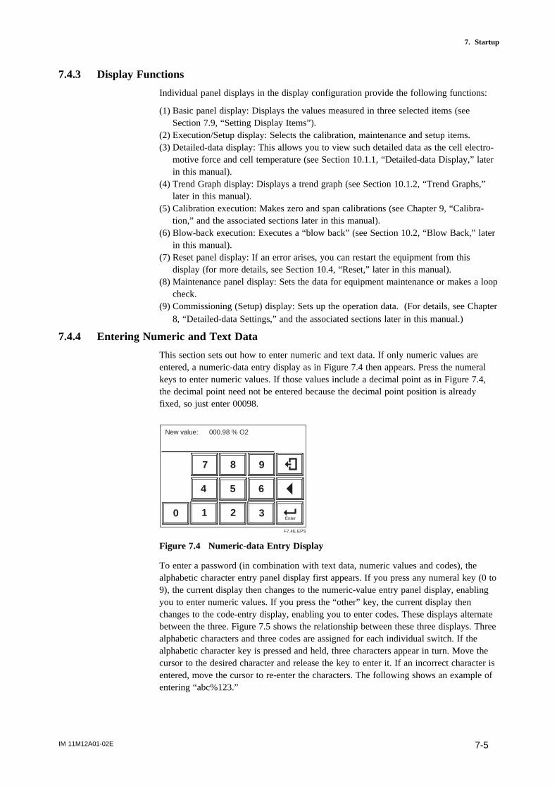
IM 11M12A01-02E 7-5
7. Startup
7.4.3 Display Functions
Individual panel displays in the display configuration provide the following functions:
(1) Basic panel display: Displays the values measured in three selected items (seeSection 7.9, “Setting Display Items”).
(2) Execution/Setup display: Selects the calibration, maintenance and setup items.(3) Detailed-data display: This allows you to view such detailed data as the cell electro-
motive force and cell temperature (see Section 10.1.1, “Detailed-data Display,” laterin this manual).
(4) Trend Graph display: Displays a trend graph (see Section 10.1.2, “Trend Graphs,”later in this manual).
(5) Calibration execution: Makes zero and span calibrations (see Chapter 9, “Calibra-tion,” and the associated sections later in this manual).
(6) Blow-back execution: Executes a “blow back” (see Section 10.2, “Blow Back,” laterin this manual).
(7) Reset panel display: If an error arises, you can restart the equipment from thisdisplay (for more details, see Section 10.4, “Reset,” later in this manual).
(8) Maintenance panel display: Sets the data for equipment maintenance or makes a loopcheck.
(9) Commissioning (Setup) display: Sets up the operation data. (For details, see Chapter8, “Detailed-data Settings,” and the associated sections later in this manual.)
7.4.4 Entering Numeric and Text Data
This section sets out how to enter numeric and text data. If only numeric values areentered, a numeric-data entry display as in Figure 7.4 then appears. Press the numeralkeys to enter numeric values. If those values include a decimal point as in Figure 7.4,the decimal point need not be entered because the decimal point position is alreadyfixed, so just enter 00098.
Enter
New value: 000.98 % O2
0 1
4
7
2 3
5 6
8 9
F7.4E.EPS
Figure 7.4 Numeric-data Entry Display
To enter a password (in combination with text data, numeric values and codes), thealphabetic character entry panel display first appears. If you press any numeral key (0 to9), the current display then changes to the numeric-value entry panel display, enablingyou to enter numeric values. If you press the “other” key, the current display thenchanges to the code-entry display, enabling you to enter codes. These displays alternatebetween the three. Figure 7.5 shows the relationship between these three displays. Threealphabetic characters and three codes are assigned for each individual switch. If thealphabetic character key is pressed and held, three characters appear in turn. Move thecursor to the desired character and release the key to enter it. If an incorrect character isentered, move the cursor to re-enter the characters. The following shows an example ofentering “abc%123.”
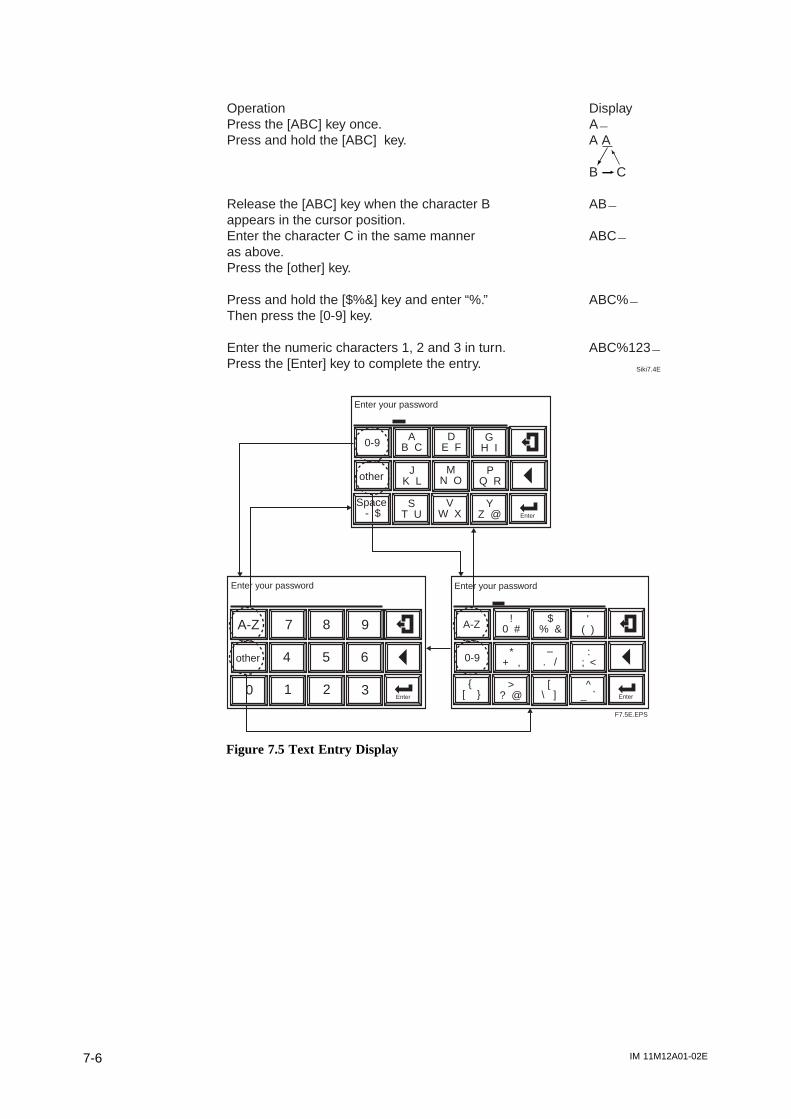
IM 11M12A01-02E7-6
Operation DisplayPress the [ABC] key once. A2Press and hold the [ABC] key. A A
B C
Release the [ABC] key when the character B AB2appears in the cursor position.Enter the character C in the same manner ABC2as above.Press the [other] key.
Press and hold the [$%&] key and enter “%.” ABC%2Then press the [0-9] key.
Enter the numeric characters 1, 2 and 3 in turn. ABC%1232Press the [Enter] key to complete the entry. Siki7.4E
F7.5E.EPS
Enter
other
Enter your password
AB C
DE F
GH I
JK L
MN O
PQ R
ST U
VW X
YZ @
0-9
Space - $
Enter0 1
4
7
2 3
5 6
8 9A-Z
other
Enter your password
Enter
0-9
Enter your password
!0 #
$% &
'( )
*+ ,
–. /
:; <
>? @
[\ ]
^_ `
A-Z
[
Figure 7.5 Text Entry Display

IM 11M12A01-02E 7-7
7. Startup
7.5 Confirmation of Converter Type SettingThis converter can be used for both the Oxygen Analyzer and the Humidity Analyzer.Before setting the operating data, be sure to check that the desired converter model hasbeen set.
Note that if the converter type setting is changed, the operating data that have been setare then initialized and the default settings remain. To set the desired operating data,follow these steps:
(1) Press the setup key.(2) Use the. key to select Setup and press the [Enter] key.(3) In the password display, enter the [Enter] key. If the password is to be set again,
enter the new password (for details, see Section 8.6.5, “Setting Passwords,” later inthis manual).
(4) The Setup display shown in Figure 7.6 appears. Select “Basic setup” and press the[Enter] key.
(5) The Basic setup display shown in Figure 7.7 then appears. Confirm the currently setconverter type. If the Humidity Analyzer option /HS was selected at the time ofpurchase, the converter was set for high-temperature humidity use before shipment.
(6) If the converter type is to be changed, press the [Enter] key. The display shown inFigure 7.8 then appears.
(7) Use the . key to select the type of equipment. Then press the [Enter] key to com-plete the converter selection.
(8) If the type of converter is changed after setting the operating data, those data are theninitialized and the default settings remain. Reset the operating data to meet the newtype of equipment.
Enter
Commissioning
r mA-output setup
r Alarms setup
r Contact setup
r Others
Basic setup
F7.6E.EPS
Enter
Basic setup This instrument is for OxygenPlease note:changing thisBasic setting will return ALLother setting to Default!!
r Detector is ZR22
r Select measure gas: Wet
F7.7E.EPS
Figure 7.6 Setup Display Figure 7.7 Basic Setup
This instrument is for Please note:changing thisBasic setting will return ALLother setting to Default!!
r Detector is ZR22
r Select measure gas: Wet Enter
Basic setup
OxygenHumidity
F7.8E.EPS
Figure 7.8 Equipment Setup
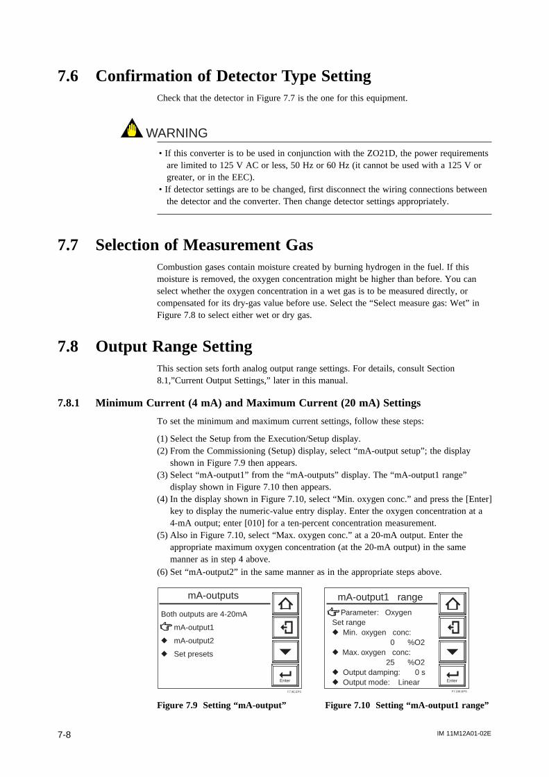
IM 11M12A01-02E7-8
7.6 Confirmation of Detector Type SettingCheck that the detector in Figure 7.7 is the one for this equipment.
WARNING
• If this converter is to be used in conjunction with the ZO21D, the power requirementsare limited to 125 V AC or less, 50 Hz or 60 Hz (it cannot be used with a 125 V orgreater, or in the EEC).
• If detector settings are to be changed, first disconnect the wiring connections betweenthe detector and the converter. Then change detector settings appropriately.
7.7 Selection of Measurement GasCombustion gases contain moisture created by burning hydrogen in the fuel. If thismoisture is removed, the oxygen concentration might be higher than before. You canselect whether the oxygen concentration in a wet gas is to be measured directly, orcompensated for its dry-gas value before use. Select the “Select measure gas: Wet” inFigure 7.8 to select either wet or dry gas.
7.8 Output Range SettingThis section sets forth analog output range settings. For details, consult Section8.1,”Current Output Settings,” later in this manual.
7.8.1 Minimum Current (4 mA) and Maximum Current (20 mA) Settings
To set the minimum and maximum current settings, follow these steps:
(1) Select the Setup from the Execution/Setup display.(2) From the Commissioning (Setup) display, select “mA-output setup”; the display
shown in Figure 7.9 then appears.(3) Select “mA-output1” from the “mA-outputs” display. The “mA-output1 range”
display shown in Figure 7.10 then appears.(4) In the display shown in Figure 7.10, select “Min. oxygen conc.” and press the [Enter]
key to display the numeric-value entry display. Enter the oxygen concentration at a4-mA output; enter [010] for a ten-percent concentration measurement.
(5) Also in Figure 7.10, select “Max. oxygen conc.” at a 20-mA output. Enter theappropriate maximum oxygen concentration (at the 20-mA output) in the samemanner as in step 4 above.
(6) Set “mA-output2” in the same manner as in the appropriate steps above.
Both outputs are 4-20mA
mA-output1
r mA-output2
r Set presets
Enter
mA-outputs
F7.9E.EPS
Parameter: OxygenSet ranger Min. oxygen conc: 0 %O2r Max. oxygen conc: 25 %O2r Output damping: 0 sr Output mode: Linear Enter
mA-output1 range
F7.10E.EPS
Figure 7.9 Setting “mA-output” Figure 7.10 Setting “mA-output1 range”

IM 11M12A01-02E 7-9
7. Startup
7.9 Setting Display ItemThis section briefly describes the display item settings shown in Figure 7.11, “BasicPanel Display.”
F7.11E.EPS
Tag:
21.0%O2
17.43mA -Output117.43mA -Output2
Primary value
Secondary value
Tertiary value
Tag name
Figure 7.11 Basic Panel Display
(1) Press the Setup key in the basic panel display to display the Execution/Setup display.Then select Maintenance in the Execution/Setup display.
(2) Select the Display setup from the Maintenance panel display (Figure 7.12). TheDisplay setup display (Figure 7.13) then appears.
(3) In the above Display setup display, select the Display item. The Display item display(Figure 7.14) then appears. From this display, select the Primary value and press the[Enter] key to display the Display item selection display (Figure 7.15).
(4) Select the Secondary and Tertiary values in the same manner as in the steps above.(5) Consult Table 7.2, “Display Items,” enabling the selection of display items in
individual display areas.
Enter
Display setup
r Calibration setup
r Blow back setup
r mA-output loop check
r Contact check
Maintenance
F7.12.EPS
Enter
Display item
r Trend graph
r Auto return time: 0min
r Language: English
Display setup
F7.13.EPS
Figure 7.12 Maintenance Panel Display Figure 7.13 Display Setup
Enter
Primary value: Oxygenr Secondary value: mA-output1r Tertiary value: mA-output2r Tag name:
Display item
F7.14.EPS
Primary value: Oxygenr Secondary value: mA-output1r Tertiary value: mA-output2r Tag name:
Enter
OxygenItem of output1 dampingItem of output2 damping
Display item
F7.15.EPS
Figure 7.14 Display Item Display Figure 7.15 Display Item Selection
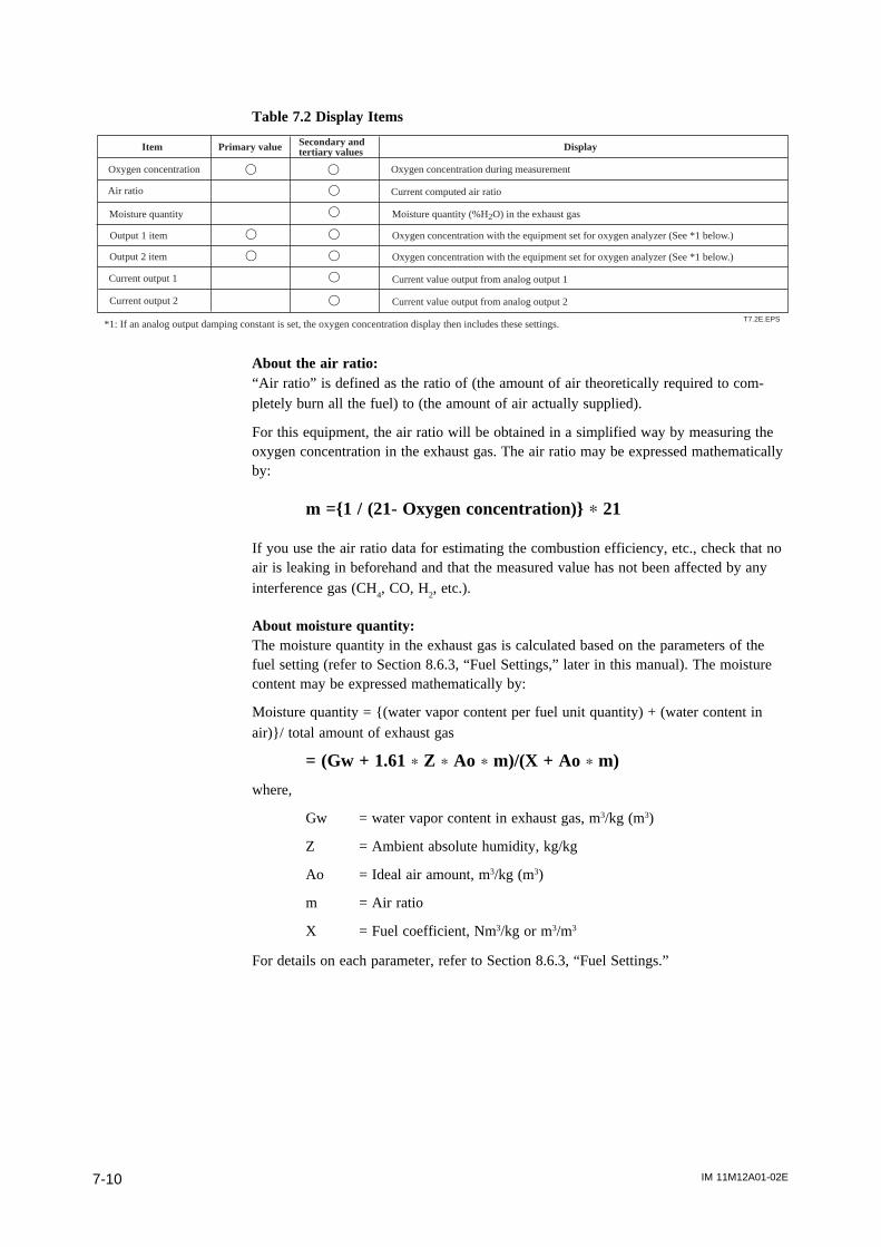
IM 11M12A01-02E7-10
Table 7.2 Display Items
T7.2E.EPS *1: If an analog output damping constant is set, the oxygen concentration display then includes these settings.
Item Primary value Secondary andtertiary values
Oxygen concentration Oxygen concentration during measurement
Air ratio Current computed air ratio
Moisture quantity Moisture quantity (%H2O) in the exhaust gas
Output 1 item Oxygen concentration with the equipment set for oxygen analyzer (See *1 below.)
Output 2 item Oxygen concentration with the equipment set for oxygen analyzer (See *1 below.)
Current output 1 Current value output from analog output 1
Current output 2 Current value output from analog output 2
s s
s
s
s
s
s
s
s
s
Display
About the air ratio:“Air ratio” is defined as the ratio of (the amount of air theoretically required to com-pletely burn all the fuel) to (the amount of air actually supplied).
For this equipment, the air ratio will be obtained in a simplified way by measuring theoxygen concentration in the exhaust gas. The air ratio may be expressed mathematicallyby:
m =1 / (21- Oxygen concentration) p 21
If you use the air ratio data for estimating the combustion efficiency, etc., check that noair is leaking in beforehand and that the measured value has not been affected by anyinterference gas (CH
4, CO, H
2, etc.).
About moisture quantity:The moisture quantity in the exhaust gas is calculated based on the parameters of thefuel setting (refer to Section 8.6.3, “Fuel Settings,” later in this manual). The moisturecontent may be expressed mathematically by:
Moisture quantity = (water vapor content per fuel unit quantity) + (water content in
air)/ total amount of exhaust gas
= (Gw + 1.61 p Z p Ao p m)/(X + Ao p m)
where,
Gw = water vapor content in exhaust gas, m3/kg (m3)
Z = Ambient absolute humidity, kg/kg
Ao = Ideal air amount, m3/kg (m3)
m = Air ratio
X = Fuel coefficient, Nm3/kg or m3/m3
For details on each parameter, refer to Section 8.6.3, “Fuel Settings.”

IM 11M12A01-02E 7-11
7. Startup
7.10 Checking Current LoopThe set current can be output as an analog output.
(1) Press the Setup key on the basic panel display to display the Execution/Setupdisplay. Then select Maintenance in the Execution/Setup display.
(2) Select “mA-output loop check” in the Maintenance panel display to display the “mA-output loop check” display, enabling you to check “mA-output1” and “mA-output2.”Select the desired output terminal for current-loop checking (see Figure 7.15.1).
(3) At the time of entering the numeric-data entry display, the output current will changeto 4 mA (default value). If the desired current is entered, the corresponding outputwill be provided.
mA - output 1
r mA - output 2
Enter
mA - output loop check
F7.15.1E.EPS
Figure 7.15.1 “mA-output loop check” Panel Display

IM 11M12A01-02E7-12
7.11 Checking Contact I/OConduct the contact input and output checking as well as operational checking of the
solenoid valves for automatic calibration.
7.11.1 Checking Contact Output
To check the contact output, follow these steps:
(1) Press the Setup key in the basic panel display to display the Execution/Setup display.Select Maintenance in that display.
(2) Select Contact check then contact output in the Maintenance panel display to displaythe Output contact check display (see Figure 7.15.2).
(3) In this display, select the desired output contact for checking. The display, whichenables the closing and opening of contacts, then appears. Use the display to conductcontinuity checking.
Output contact 1 : Open
r Output contact 2 : Open
r Output contact 3 : Open
r Output contact 4 : Open
Enter
Output contacts
F7.15.2E.EPS
Figure 7.15.2 Output Contact Check Panel Display
CAUTION
• If you conduct an open-close check for contact output 4, Error 1 or Error 2 will occur.This is because the built-in heater power of the detector, which is connected tocontact output 4, is turned off during the above check. So, if the above error occurs,reset the equipment or turn the power off and then back on to restart (refer to Section10.4, “Reset,” later in this manual).
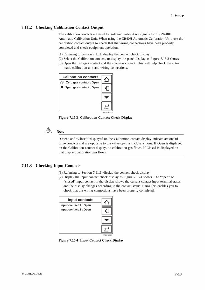
IM 11M12A01-02E 7-13
7. Startup
7.11.2 Checking Calibration Contact Output
The calibration contacts are used for solenoid valve drive signals for the ZR40HAutomatic Calibration Unit. When using the ZR40H Automatic Calibration Unit, use thecalibration contact output to check that the wiring connections have been properlycompleted and check equipment operation.
(1) Referring to Section 7.11.1, display the contact check display.(2) Select the Calibration contacts to display the panel display as Figure 7.15.3 shows.(3) Open the zero-gas contact and the span-gas contact. This will help check the auto-
matic calibration unit and wiring connections.
Zero gas contact : Open
r Span gas contact : Open
Enter
Calibration contacts
F7.15.3E.EPS
Figure 7.15.3 Calibration Contact Check Display
Note
“Open” and “Closed” displayed on the Calibration contact display indicate actions ofdrive contacts and are opposite to the valve open and close actions. If Open is displayedon the Calibration contact display, no calibration gas flows. If Closed is displayed onthat display, calibration gas flows.
7.11.3 Checking Input Contacts
(1) Referring to Section 7.11.1, display the contact check display.(2) Display the input contact check display as Figure 7.15.4 shows. The “open” or
“closed” input contact in the display shows the current contact input terminal statusand the display changes according to the contact status. Using this enables you tocheck that the wiring connections have been properly completed.
Input contact 1 : Open
Input contact 2 : Open
Enter
Input contacts
F7.15.4E.EPS
Figure 7.15.4 Input Contact Check Display
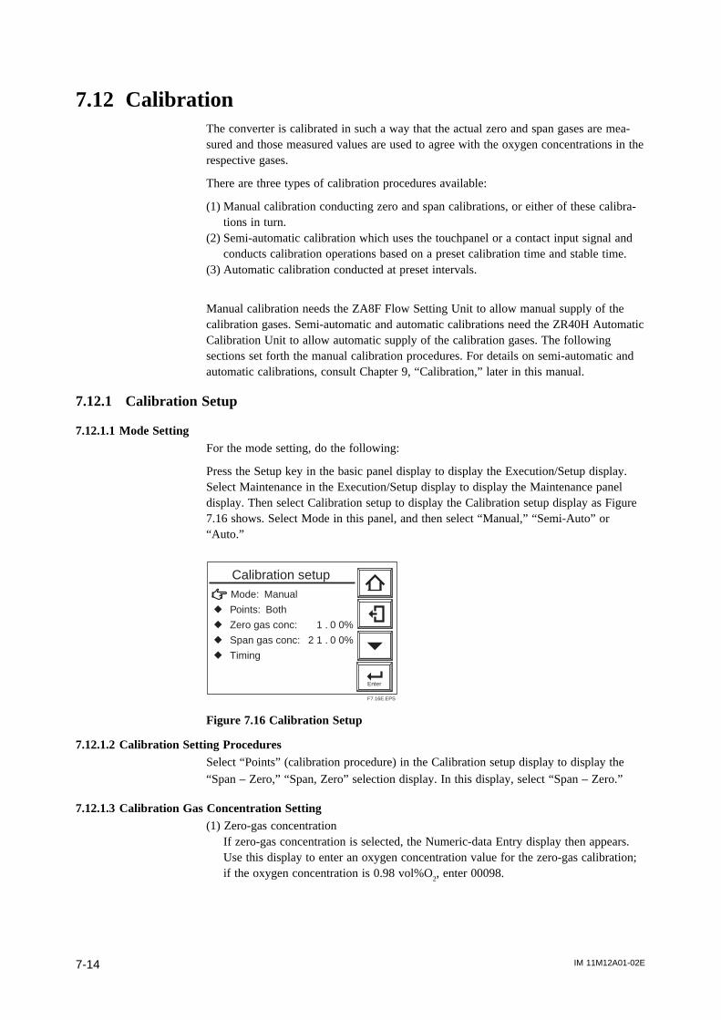
IM 11M12A01-02E7-14
7.12 CalibrationThe converter is calibrated in such a way that the actual zero and span gases are mea-sured and those measured values are used to agree with the oxygen concentrations in therespective gases.
There are three types of calibration procedures available:
(1) Manual calibration conducting zero and span calibrations, or either of these calibra-tions in turn.
(2) Semi-automatic calibration which uses the touchpanel or a contact input signal andconducts calibration operations based on a preset calibration time and stable time.
(3) Automatic calibration conducted at preset intervals.
Manual calibration needs the ZA8F Flow Setting Unit to allow manual supply of thecalibration gases. Semi-automatic and automatic calibrations need the ZR40H AutomaticCalibration Unit to allow automatic supply of the calibration gases. The followingsections set forth the manual calibration procedures. For details on semi-automatic andautomatic calibrations, consult Chapter 9, “Calibration,” later in this manual.
7.12.1 Calibration Setup
7.12.1.1 Mode SettingFor the mode setting, do the following:
Press the Setup key in the basic panel display to display the Execution/Setup display.Select Maintenance in the Execution/Setup display to display the Maintenance paneldisplay. Then select Calibration setup to display the Calibration setup display as Figure7.16 shows. Select Mode in this panel, and then select “Manual,” “Semi-Auto” or“Auto.”
Enter
Mode: Manual
r Points: Both
r Zero gas conc: 1 . 0 0%
r Span gas conc: 2 1 . 0 0%
r Timing
Calibration setup
F7.16E.EPS
Figure 7.16 Calibration Setup
7.12.1.2 Calibration Setting ProceduresSelect “Points” (calibration procedure) in the Calibration setup display to display the
“Span – Zero,” “Span, Zero” selection display. In this display, select “Span – Zero.”
7.12.1.3 Calibration Gas Concentration Setting(1) Zero-gas concentration
If zero-gas concentration is selected, the Numeric-data Entry display then appears.Use this display to enter an oxygen concentration value for the zero-gas calibration;if the oxygen concentration is 0.98 vol%O
2, enter 00098.
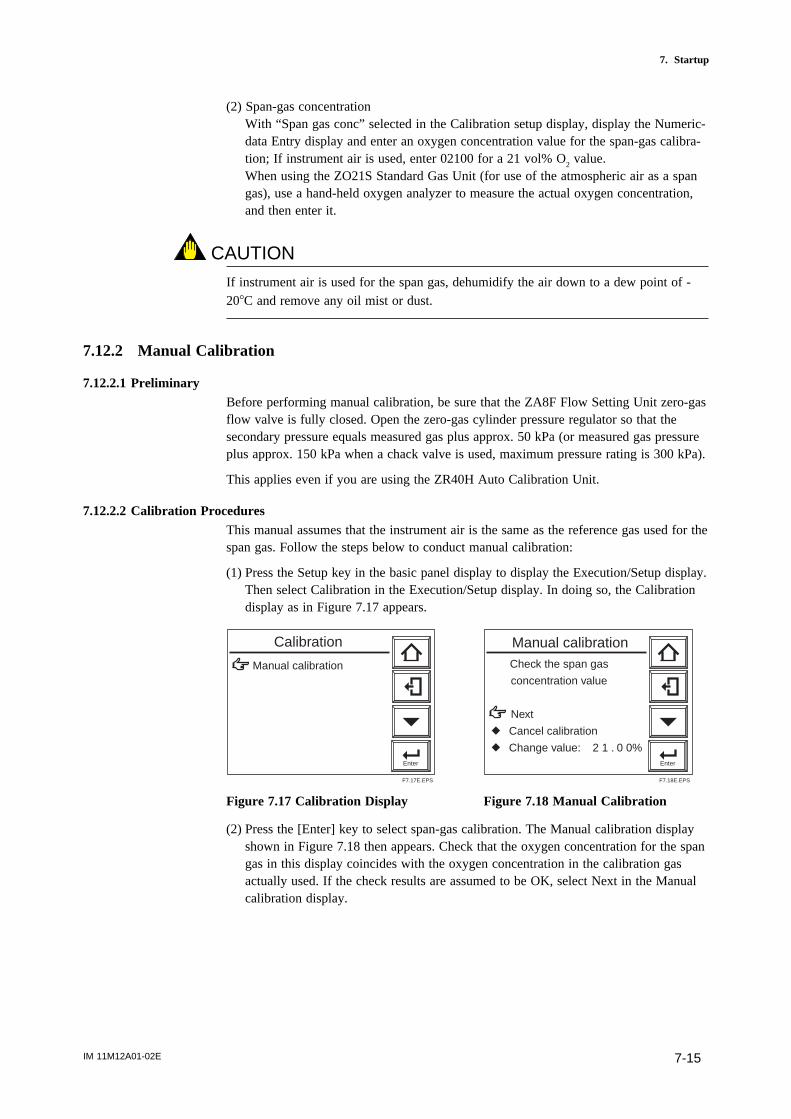
IM 11M12A01-02E 7-15
7. Startup
(2) Span-gas concentrationWith “Span gas conc” selected in the Calibration setup display, display the Numeric-data Entry display and enter an oxygen concentration value for the span-gas calibra-tion; If instrument air is used, enter 02100 for a 21 vol% O
2 value.
When using the ZO21S Standard Gas Unit (for use of the atmospheric air as a spangas), use a hand-held oxygen analyzer to measure the actual oxygen concentration,and then enter it.
CAUTION
If instrument air is used for the span gas, dehumidify the air down to a dew point of -208C and remove any oil mist or dust.
7.12.2 Manual Calibration
7.12.2.1 PreliminaryBefore performing manual calibration, be sure that the ZA8F Flow Setting Unit zero-gasflow valve is fully closed. Open the zero-gas cylinder pressure regulator so that thesecondary pressure equals measured gas plus approx. 50 kPa (or measured gas pressureplus approx. 150 kPa when a chack valve is used, maximum pressure rating is 300 kPa).
This applies even if you are using the ZR40H Auto Calibration Unit.
7.12.2.2 Calibration ProceduresThis manual assumes that the instrument air is the same as the reference gas used for thespan gas. Follow the steps below to conduct manual calibration:
(1) Press the Setup key in the basic panel display to display the Execution/Setup display.Then select Calibration in the Execution/Setup display. In doing so, the Calibrationdisplay as in Figure 7.17 appears.
Enter
Calibration
Manual calibration
F7.17E.EPS
Check the span gas
concentration value
Next
r Cancel calibration
r Change value: 2 1 . 0 0%Enter
Manual calibration
F7.18E.EPS
Figure 7.17 Calibration Display Figure 7.18 Manual Calibration
(2) Press the [Enter] key to select span-gas calibration. The Manual calibration displayshown in Figure 7.18 then appears. Check that the oxygen concentration for the spangas in this display coincides with the oxygen concentration in the calibration gasactually used. If the check results are assumed to be OK, select Next in the Manualcalibration display.
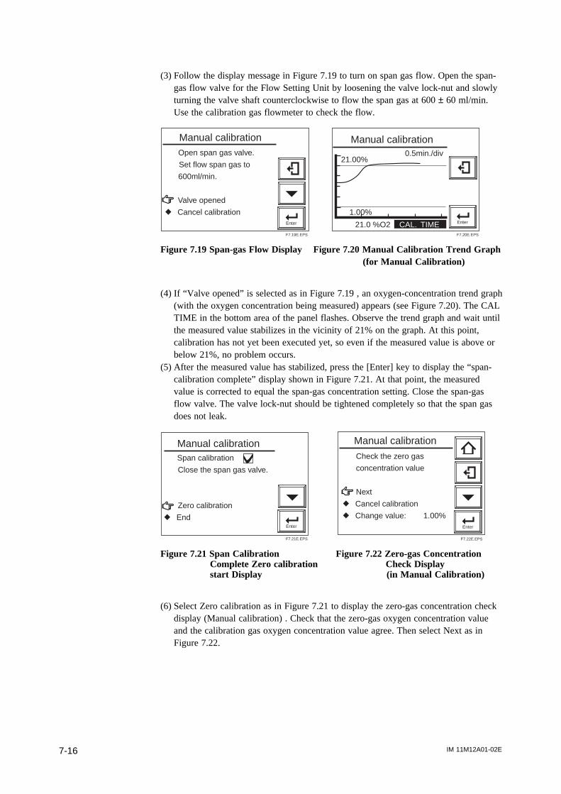
IM 11M12A01-02E7-16
(3) Follow the display message in Figure 7.19 to turn on span gas flow. Open the span-gas flow valve for the Flow Setting Unit by loosening the valve lock-nut and slowlyturning the valve shaft counterclockwise to flow the span gas at 600 ± 60 ml/min.Use the calibration gas flowmeter to check the flow.
Enter
Open span gas valve.
Set flow span gas to
600ml/min.
Valve opened
r Cancel calibration
Manual calibration
F7.19E.EPS
Enter
21.00%0.5min./div
1.00%
21.0 %O2 CAL. TIME
Manual calibration
F7.20E.EPS
Figure 7.19 Span-gas Flow Display Figure 7.20 Manual Calibration Trend Graph (for Manual Calibration)
(4) If “Valve opened” is selected as in Figure 7.19 , an oxygen-concentration trend graph(with the oxygen concentration being measured) appears (see Figure 7.20). The CALTIME in the bottom area of the panel flashes. Observe the trend graph and wait untilthe measured value stabilizes in the vicinity of 21% on the graph. At this point,calibration has not yet been executed yet, so even if the measured value is above orbelow 21%, no problem occurs.
(5) After the measured value has stabilized, press the [Enter] key to display the “span-calibration complete” display shown in Figure 7.21. At that point, the measuredvalue is corrected to equal the span-gas concentration setting. Close the span-gasflow valve. The valve lock-nut should be tightened completely so that the span gasdoes not leak.
Enter
Span calibration
Close the span gas valve.
Zero calibration
r End
Manual calibration
F7.21E.EPS
Enter
Check the zero gas
concentration value
Next
r Cancel calibration
r Change value: 1.00%
Manual calibration
F7.22E.EPS
Figure 7.21 Span Calibration Figure 7.22 Zero-gas ConcentrationComplete Zero calibration Check Displaystart Display (in Manual Calibration)
(6) Select Zero calibration as in Figure 7.21 to display the zero-gas concentration checkdisplay (Manual calibration) . Check that the zero-gas oxygen concentration valueand the calibration gas oxygen concentration value agree. Then select Next as inFigure 7.22.
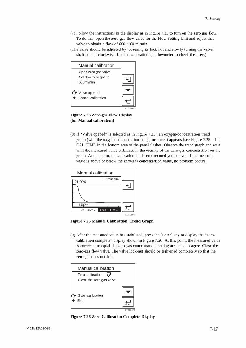
IM 11M12A01-02E 7-17
7. Startup
(7) Follow the instructions in the display as in Figure 7.23 to turn on the zero gas flow.To do this, open the zero-gas flow valve for the Flow Setting Unit and adjust thatvalve to obtain a flow of 600 ± 60 ml/min.
(The valve should be adjusted by loosening its lock nut and slowly turning the valveshaft counterclockwise. Use the calibration gas flowmeter to check the flow.)
Enter
Open zero gas valve.
Set flow zero gas to
600ml/min.
Valve opened
r Cancel calibration
Manual calibration
F7.23E.EPS
Figure 7.23 Zero-gas Flow Display(for Manual calibration)
(8) If “Valve opened” is selected as in Figure 7.23 , an oxygen-concentration trendgraph (with the oxygen concentration being measured) appears (see Figure 7.25). TheCAL TIME in the bottom area of the panel flashes. Observe the trend graph and waituntil the measured value stabilizes in the vicinity of the zero-gas concentration on thegraph. At this point, no calibration has been executed yet, so even if the measuredvalue is above or below the zero-gas concentration value, no problem occurs.
Enter
21.00%0.5min./div
1.00%
21.0%O2 CAL. TIME
Manual calibration
F7.25E.EPS
Figure 7.25 Manual Calibration, Trend Graph
(9) After the measured value has stabilized, press the [Enter] key to display the “zero-calibration complete” display shown in Figure 7.26. At this point, the measured valueis corrected to equal the zero-gas concentration, setting are made to agree. Close thezero-gas flow valve. The valve lock-nut should be tightened completely so that thezero gas does not leak.
Enter
Zero calibration
Close the zero gas valve.
Span calibration
r End
Manual calibration
F7.26E.EPS
Figure 7.26 Zero Calibration Complete Display

IM 11M12A01-02E7-18
(10) Select End in the display as shown in Figure 7.26. An oxygen concentration trendgraph (with the oxygen concentration being measured) appears and HOLD TIMEthen flashes. This time is referred to as the output-stabilization time. If the HOLDTIME has been set with the output-hold setting, the analog output remains held (referto Section 8.2, “Setting Output Hold,” later in this manual). Manual calibration iscompleted when the preset output-stabilization time elapses. This output-stabilizationtime is set to 10 minutes at the factory before shipment. If you press the [Enter] or[Return] key within the output-stabilization time, manual calibration is then com-pleted.

IM 11M12A01-02E 8-1
8. Detailed Data Setting
8. Detailed Data Setting
8.1 Current Output SettingThis section describes setting of the analog output range.
8.1.1 Setting Minimum Current (4 mA) and Maximum Current (20 mA)
To set the minimum and maximum currents, proceed as follows:
(1) Select Setup in the Execution/Setup display.(2) Select the mA-output setup in the Setup display.(3) Select mA-output1 in the mA-output display.(4) Select Min. oxygen conc. in the mA-output1 range display and press the [Enter] key.
The numeric-data entry display then appears. Enter the oxygen concentration for theminimum current (4 mA); for example, enter “010” for 10% O
2.
(5) Select Max. oxygen conc. in the mA-output1 range display and enter the oxygenconcentration for the maximum current (20 mA) in the same manner as in step 4above.
(6) Set mA-output2 in the same way as the setting procedure for mA-output1 givenabove.
8.1.2 About Input Ranges
The minimum concentration of oxygen for the minimum current (4 mA) is 0% O2 or 6%
to 76% O2. The maximum concentration of oxygen for the maximum current (20 mA)
ranges from 5% to 100% O2, and must be at least 1.3 times the concentration of oxygen
set for the minimum. If it does not fall within this input range setting, the setting will beinvalid, and the previous set values will remain.
Setting example 1If the setting (for a 4 mA current) is 10% O
2, you must set the oxygen concentration for
the maximum (20 mA) point at 13% O2 or greater.

IM 11M12A01-02E8-2
Setting example 2If the setting (for a 4 mA current) is 75% O
2, you must set the oxygen concentration for
the maximum (20 mA) point at more than 98% O2 (75 3 1.3). (Numbers after the
decimal point are rounded up.)
5
15
25
35
45
55
65
75
85
95
5 15 25 35 45 55 65 75
Minimum oxygen concentration, %O2 (for a minimum current of 4 mA)
Max
imum
oxy
gen
conc
entr
atio
n, %
O2
(for
a m
axim
um c
urre
nt o
f 20
mA
)
Ranges over which oxygen concentrations can be set
Outside ranges
F8.0E.EPS
8.1.3 Entering Output Damping Constants
If a measured value which is adversely affected by rapid changes in the measurement-gas oxygen concentration is used as the basis for control, frequent on-off actions of theoutput may result. To avoid this, the converter allows the setting of output dampingconstants ranging from 0 to 255 seconds. Select the appropriate output damping constantfrom the numeric-data entry display. To set 30 seconds, enter 030.
8.1.4 Selection of Output Mode
You can select linear or logarithmic output mode. The former provides a linear relation-ship between the analog output signal and oxygen concentration. The latter provideslogarithmic characteristic. Press the [Enter] key in the output mode display. A linear/logarithmic selection display then appears. Select the desired mode.
CAUTION
• When you select logarithmic mode, the minimum output remains constant at 0.1% O2,
and the minimum oxygen concentration value remains unchanged.

IM 11M12A01-02E 8-3
8. Detailed Data Setting
8.1.5 Default Values
When the analyzer is delivered or reset to defaults, the output current default settings byas shown in Table 8.1.1.
Table 8.1.1 Output Current Default Values
Item Default setting
Min. oxygen concentration 0% O2
Max. oxygen concentration 25% O2
Output damping constant 0 (seconds)
Output mode Linear
T8.1.1E.EPS
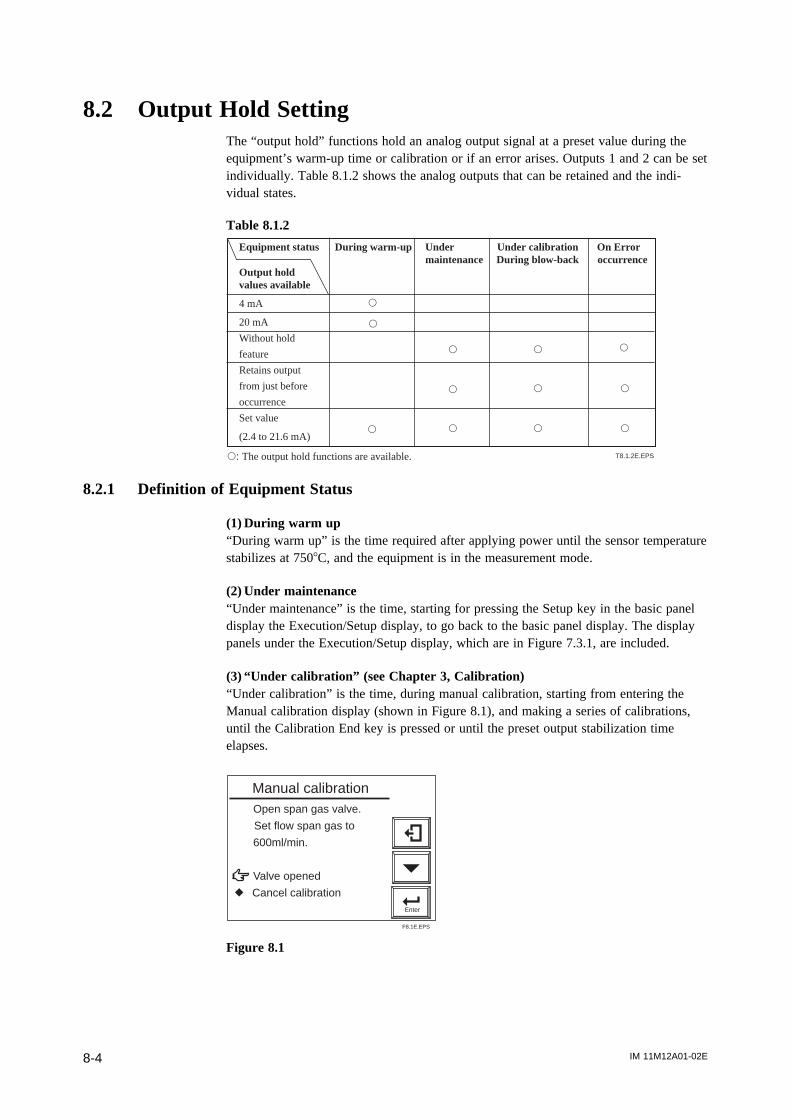
IM 11M12A01-02E8-4
8.2 Output Hold SettingThe “output hold” functions hold an analog output signal at a preset value during theequipment’s warm-up time or calibration or if an error arises. Outputs 1 and 2 can be setindividually. Table 8.1.2 shows the analog outputs that can be retained and the indi-vidual states.
Table 8.1.2
Equipment status During warm-up Under Under calibration On Error maintenance During blow-back occurrence
Output hold values available
4 mA
20 mA
Without hold
feature
Retains output
from just before
occurrence
Set value
(2.4 to 21.6 mA)
s: The output hold functions are available.
s
s
s
s
s
s
s s
s
ss
s
T8.1.2E.EPS
8.2.1 Definition of Equipment Status
(1) During warm up“During warm up” is the time required after applying power until the sensor temperaturestabilizes at 7508C, and the equipment is in the measurement mode.
(2) Under maintenance“Under maintenance” is the time, starting for pressing the Setup key in the basic paneldisplay the Execution/Setup display, to go back to the basic panel display. The displaypanels under the Execution/Setup display, which are in Figure 7.3.1, are included.
(3) “Under calibration” (see Chapter 3, Calibration)“Under calibration” is the time, during manual calibration, starting from entering theManual calibration display (shown in Figure 8.1), and making a series of calibrations,until the Calibration End key is pressed or until the preset output stabilization timeelapses.
Enter
Open span gas valve.
Set flow span gas to
600ml/min.
Valve opened
r Cancel calibration
Manual calibration
F8.1E.EPS
Figure 8.1

IM 11M12A01-02E 8-5
8. Detailed Data Setting
For semi-automatic calibration, “under calibration” is the time required from enteringcalibration instructions to perform a, either by using the touchpanel or by a contactinput, calibration until the output stabilization time elapses.
For automatic calibration, “under calibration” is the time required, after performing anappropriate calibration until the output stabilization time elapses.
(4) During “Blow back” (see Section 10.2, “Blow back,” later in this manual)
During semi-automatic blow back:“During blow back” is the time required after pressing the blow-back start key, by usingthe touchpanel or entering a blow back start instruction by using a contact input, untilthe blow back time and output stabilization time elapse.
During automatic blow back:“During blow back” is the time required after reaching the blow-back start time until theblow-back time and output stabilization time elapse.
(5) On Error occurrenceThis is the time at which any of Errors 1 to 4 occurs.
8.2.2 Preference Order of Output Hold Value
The output hold value takes the following preference order:
On error occurrence
Under calibration or during blow back
During warm-up
Under maintenance
Preference order (high) 8.2.2.siki
For example, if the output current is set to 4 mA during maintenance, and no output-hold output for during calibration is preset, the output is held at 4 mA during themaintenance display. However, the output hold is released at the time of starting thecalibration, and the output will be again held at 4 mA after completing the calibrationand when the output stabilization time elapses.
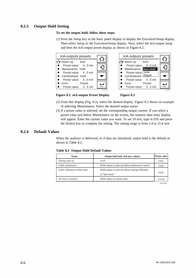
IM 11M12A01-02E8-6
8.2.3 Output Hold Setting
To set the output hold, follow these steps:
(1) Press the Setup key in the basic panel display to display the Execution/Setup display.Then select Setup in the Execution/Setup display. Next, select the mA-output setupand then the mA-output preset display as shown in Figure 8.2.
Warm up: 4mAr Preset value: 4 . 0 mAr Maintenance: Holdr Preset value: 4 . 0 mAr Cal.blowback: Holdr Preset value: 4 . 0 mAr Error: Presetr Preset value: 3 . 4 mA Enter
mA-outputs presets
F8.2E.EPS
Warm up: 4mAr Preset value: 4 . 0 mAr Maintenance: Holdr Preset value: 4.0mAr Cal.blowback: Holdr Preset value: 4 . 0 mAr Error: Presetr Preset value: 3 . 4 mA Enter
mA-outputs presets
Non-HoldHoldPreset
F8.3E.EPS
Figure 8.2 mA-output Preset Display Figure 8.3
(2) From this display (Fig. 8.2), select the desired display. Figure 8.3 shows an exampleof selecting Maintenance. Select the desired output status.
(3) If a preset value is selected, set the corresponding output current. If you select apreset value just below Maintenance on the screen, the numeric-data entry displaywill appear. Enter the current value you want. To set 10 mA, type in 010 and pressthe [Enter] key to complete the setting. The setting range is from 2.4 to 21.6 mA.
8.2.4 Default Values
When the analyzer is delivered, or if data are initialized, output hold is the default asshown in Table 8.2.
Table 8.2 Output Hold Default Values
Status Output hold (min. and max. values)
During warm-up 4 mA
Under maintenance Holds output at value just before maintenance started.
Under calibration or blow-back Holds output at value just before starting calibration
or "blow-back."
On Error occurrence Holds output at a preset value.
T8.2E.EPS
Preset value
4 mA
4 mA
4 mA
3.4 mA

IM 11M12A01-02E 8-7
8. Detailed Data Setting
8.3 Setting Oxygen Concentration AlarmsThe analyzer enables the setting of four alarms — high-high, high, low, and low-lowalarms — depending upon the oxygen concentration. The following section sets out thealarm operations and setting procedures.
8.3.1 Alarm Values
(1) High-high and high alarm valuesIf high-high and high alarm values are set to ON, then alarms occur if measured valvesexceed the alarm set values. The oxygen alarm set values can be set in the range 0 to100% O
2.
(2) Low and low-low alarm valuesIf low-low and low alarm values ore set, then alarms occur if measured values fallbelow the alarm set values. The oxygen alarm set values can be set in the range 0 to100% O
2.
8.3.2 Alarm Output Actions
If the measured values of the oxygen concentration fluctuate between normal (steady-state) values and alarm setting, there may be a lot of alarm-output issuing and canceling.To avoid this, set the alarm delay and hysteresis for alarm canceling under the alarmoutput conditions, as Figure 8.4 shows. When the delay time is set, an alarm will not beissued so quickly even the measured value differs from the steady-state and enters thealarm setpoint range. If the measured value remains within the alarm setpoint range for acertain period of time (for the preset delay time), an alarm will result. On the other hand,there will be a simila delay each time the measured value returns to the steady statefrom the alarm setpoint range (canceling the alarm status). If hysteresis is set, alarmswill be canceled when the measured value is less than or greater than the preset hyster-esis values. If both the delay time and hysteresis are set, an alarm will be issued if themeasured value is in the alarm setpoint range and the delay time has elapsed. When thealarm is reset (canceled), it is required that the measured value be beyond the presethysteresis value and that the preset delay time has elapsed. Refer to Figure 8.4 for anyfurther alarm output actions. The delayed time and hysteresis settings are common to allalarm points.
Delay time: 5 seconds
7.5%High-limit alarm setpoint
5.5%
Oxygen concentration
Alarm output ONOFF
Hysteresis2.0%
A B C D
Alarm range
Delay time: 5 seconds
Delay time: 5 seconds
F8.4E.EPS
Figure 8.4 Alarm Output Action
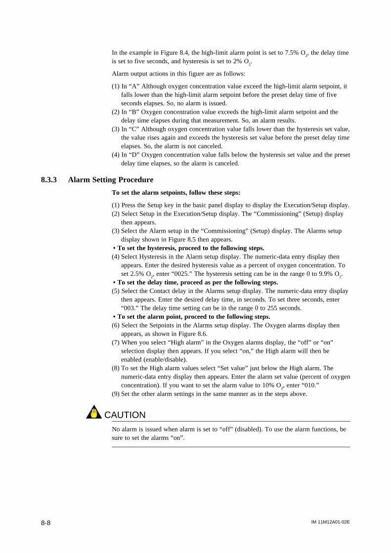
IM 11M12A01-02E8-8
In the example in Figure 8.4, the high-limit alarm point is set to 7.5% O2, the delay time
is set to five seconds, and hysteresis is set to 2% O2.
Alarm output actions in this figure are as follows:
(1) In “A” Although oxygen concentration value exceed the high-limit alarm setpoint, itfalls lower than the high-limit alarm setpoint before the preset delay time of fiveseconds elapses. So, no alarm is issued.
(2) In “B” Oxygen concentration value exceeds the high-limit alarm setpoint and thedelay time elapses during that measurement. So, an alarm results.
(3) In “C” Although oxygen concentration value falls lower than the hysteresis set value,the value rises again and exceeds the hysteresis set value before the preset delay timeelapses. So, the alarm is not canceled.
(4) In “D” Oxygen concentration value falls below the hysteresis set value and the presetdelay time elapses, so the alarm is canceled.
8.3.3 Alarm Setting Procedure
To set the alarm setpoints, follow these steps:
(1) Press the Setup key in the basic panel display to display the Execution/Setup display.(2) Select Setup in the Execution/Setup display. The “Commissioning” (Setup) display
then appears.(3) Select the Alarm setup in the “Commissioning” (Setup) display. The Alarms setup
display shown in Figure 8.5 then appears.• To set the hysteresis, proceed to the following steps.(4) Select Hysteresis in the Alarm setup display. The numeric-data entry display then
appears. Enter the desired hysteresis value as a percent of oxygen concentration. Toset 2.5% O
2, enter “0025.” The hysteresis setting can be in the range 0 to 9.9% O
2.
• To set the delay time, proceed as per the following steps.(5) Select the Contact delay in the Alarms setup display. The numeric-data entry display
then appears. Enter the desired delay time, in seconds. To set three seconds, enter“003.” The delay time setting can be in the range 0 to 255 seconds.
• To set the alarm point, proceed to the following steps.(6) Select the Setpoints in the Alarms setup display. The Oxygen alarms display then
appears, as shown in Figure 8.6.(7) When you select “High alarm” in the Oxygen alarms display, the “off” or “on”
selection display then appears. If you select “on,” the High alarm will then beenabled (enable/disable).
(8) To set the High alarm values select “Set value” just below the High alarm. Thenumeric-data entry display then appears. Enter the alarm set value (percent of oxygenconcentration). If you want to set the alarm value to 10% O
2, enter “010.”
(9) Set the other alarm settings in the same manner as in the steps above.
CAUTIONNo alarm is issued when alarm is set to “off” (disabled). To use the alarm functions, besure to set the alarms “on”.
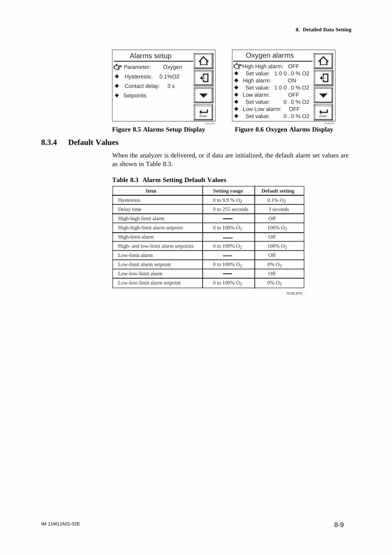
IM 11M12A01-02E 8-9
8. Detailed Data Setting
Parameter: Oxygen
r Hysteresis: 0.1%O2
r Contact delay: 3 s
r Setpoints
Enter
Alarms setup
F8.5E.EPS
High High alarm: OFFr Set value: 1 0 0 . 0 % O2r High alarm: ONr Set value: 1 0 0 . 0 % O2r Low alarm: OFFr Set value: 0 . 0 % O2r Low Low alarm: OFFr Set value: 0 . 0 % O2 Enter
Oxygen alarms
F8.6E.EPS
Figure 8.5 Alarms Setup Display Figure 8.6 Oxygen Alarms Display
8.3.4 Default Values
When the analyzer is delivered, or if data are initialized, the default alarm set values areas shown in Table 8.3.
Table 8.3 Alarm Setting Default Values
Item Setting range Default setting
Hysteresis 0 to 9.9 % O2 0.1% O2
Delay time 0 to 255 seconds 3 seconds
High-high limit alarm Off
High-high-limit alarm setpoint 0 to 100% O2 100% O2
High-limit alarm Off
High- and low-limit alarm setpoints 0 to 100% O2 100% O2
Low-limit alarm Off
Low-limit alarm setpoint 0 to 100% O2 0% O2
Low-low-limit alarm Off
Low-low-limit alarm setpoint 0 to 100% O2 0% O2
T8.3E.EPS
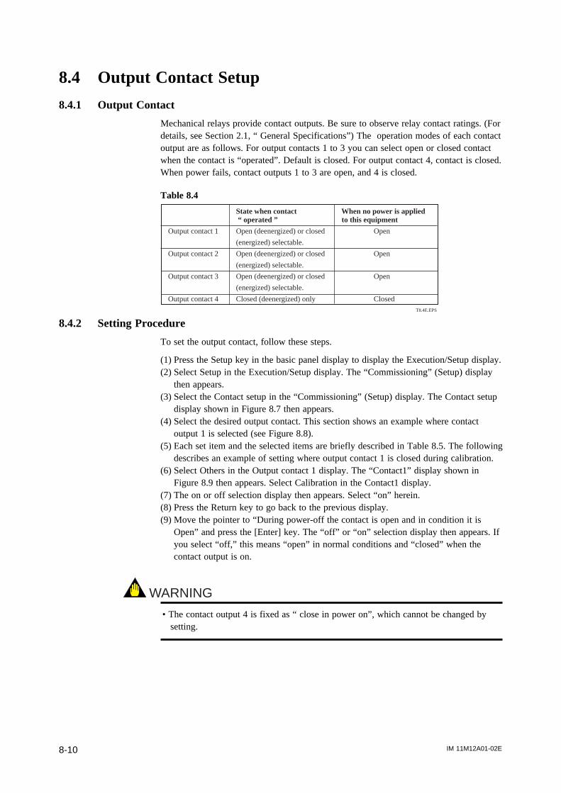
IM 11M12A01-02E8-10
8.4 Output Contact Setup
8.4.1 Output Contact
Mechanical relays provide contact outputs. Be sure to observe relay contact ratings. (Fordetails, see Section 2.1, “ General Specifications”) The operation modes of each contactoutput are as follows. For output contacts 1 to 3 you can select open or closed contactwhen the contact is “operated”. Default is closed. For output contact 4, contact is closed.When power fails, contact outputs 1 to 3 are open, and 4 is closed.
Table 8.4
T8.4E.EPS
State when contact When no power is applied “ operated ” to this equipment
Output contact 1 Open (deenergized) or closed Open
(energized) selectable.
Output contact 2 Open (deenergized) or closed Open
(energized) selectable.
Output contact 3 Open (deenergized) or closed Open
(energized) selectable.
Output contact 4 Closed (deenergized) only Closed
8.4.2 Setting Procedure
To set the output contact, follow these steps.
(1) Press the Setup key in the basic panel display to display the Execution/Setup display.(2) Select Setup in the Execution/Setup display. The “Commissioning” (Setup) display
then appears.(3) Select the Contact setup in the “Commissioning” (Setup) display. The Contact setup
display shown in Figure 8.7 then appears.(4) Select the desired output contact. This section shows an example where contact
output 1 is selected (see Figure 8.8).(5) Each set item and the selected items are briefly described in Table 8.5. The following
describes an example of setting where output contact 1 is closed during calibration.(6) Select Others in the Output contact 1 display. The “Contact1” display shown in
Figure 8.9 then appears. Select Calibration in the Contact1 display.(7) The on or off selection display then appears. Select “on” herein.(8) Press the Return key to go back to the previous display.(9) Move the pointer to “During power-off the contact is open and in condition it is
Open” and press the [Enter] key. The “off” or “on” selection display then appears. Ifyou select “off,” this means “open” in normal conditions and “closed” when thecontact output is on.
WARNING
• The contact output 4 is fixed as “ close in power on”, which cannot be changed bysetting.
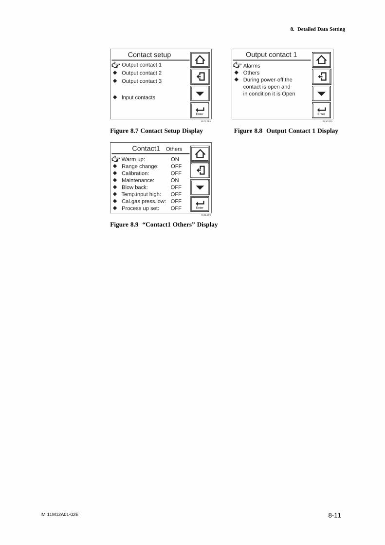
IM 11M12A01-02E 8-11
8. Detailed Data Setting
Output contact 1
r Output contact 2
r Output contact 3
r lnput contacts
Enter
Contact setup
F8.7E.EPS
Enter
Alarmsr Othersr During power-off the contact is open and in condition it is Open
Output contact 1
F8.8E.EPS
Figure 8.7 Contact Setup Display Figure 8.8 Output Contact 1 Display
Warm up: ONr Range change: OFFr Calibration: OFFr Maintenance: ONr Blow back: OFFr Temp.input high: OFFr Cal.gas press.low: OFFr Process up set: OFF Enter
Contact1 Others
F8.9E.EPS
Figure 8.9 “Contact1 Others” Display

IM 11M12A01-02E8-12
Table 8.5 Output Contact Settings
Alarm
and
Error
settings
Other
settings
Note: To provide an alarm with an output contact, be sure to make an alarm setting.
When using contact output as an answer-back signal for an input contact, be sure to make an input contact T8.5E.EPS
Item to be selected Brief description
High-high- If "high-high alarm ON" is selected, contact output occurs when the high-high-limit
limit alarm alarm is issued. To do this, it is required, in alarm setup, that the
high-high alarm be set on beforehand (see Section 8.3).
High-limit If "high alarm ON" is selected, contact output occurs when the high-limit alarm
alarm is provided. To do this, it is required, in alarm setup, that the
high-limit alarm be set on beforehand (see Section 8.3).
Low-limit If "low alarm ON" is selected, contact output occurs when the low-limit alarm is
alarm provided. To do this, it is required, in alarm setup, that the
low-limit alarm be set on beforehand (see Section 8.3).
Low-low-limit If "low-low alarm ON" is selected, contact output occurs when the low-low-limit alarm is
alarm issued. To do this, it is required, in alarm setup, that the low-low
alarm be set on beforehand (see Section 8.3).
Calibration coefficient alarm If calibration coefficient alarm is ON (enabled), then when a zero- calibration coefficient
alarm (alarm 6) or span calibration coefficient alarm (alarm 7) occurs then calibration
coefficient alarm contact output occurs (see Sec. 12.2.1 Alarms)
Startup power stabilization If set ON then contact output occurs when startup power stabilization timeout alarm
timeout alarm (alarm 8) occurs (see Sec.12.2.1 Alarms)
Error If "Error ON" is selected, contact output occurs when an error results.
(See Chapter 12, "Troubleshooting.")
Warm-up If "Warm-up ON" is selected, contact output occurs during warm-up.
For the definition of warm-up, see Section 8.2.1.
Output range If "Range Change ON" is selected, contact output occurs ("answer-back signal
change to a range change signal") while a range change signal is
applied to a contact input. To do this, it is required, in input contact setup,
that the range change be selected beforehand. For more on this, see Section 8.5.
Calibration If "Calibration ON" is selected, contact output occurs during calibration.
For the definition of "During calibration," consult Section 8.2.1.
Maintenance If "Maintenance ON" is selected, contact output occurs during maintenance.
For the definition of "During maintenance," consult Section 8.2.1.
Blow back If "Blow back ON" is selected, contact output occurs during blow back.
For the definition of "During blow back," consult Section 8.2.1.
High-limit Not supported by the oxygen analyzer.
temperature
alarm
Calibration- If "Cal. gas press. low ON" is selected, contact output occurs ("answer-back
gas press. low signal to a calibration-gas low-pressure signal")when a calibration-gas low-
pressure signal is applied to the contact input. To do this, it is required, in input
contact setup, that "Cal. gas press. Low" be selected beforehand. For more on this,
see Section 8.5.
Process upset If "Process upset" is selected, contact output occurs ("answer-back signal to
a process upset signal) when the process upset signal is applied to the contact input.
To do this, it is required, in input contact setup, that "process upset" be selected
beforehand (see Section 8.5).
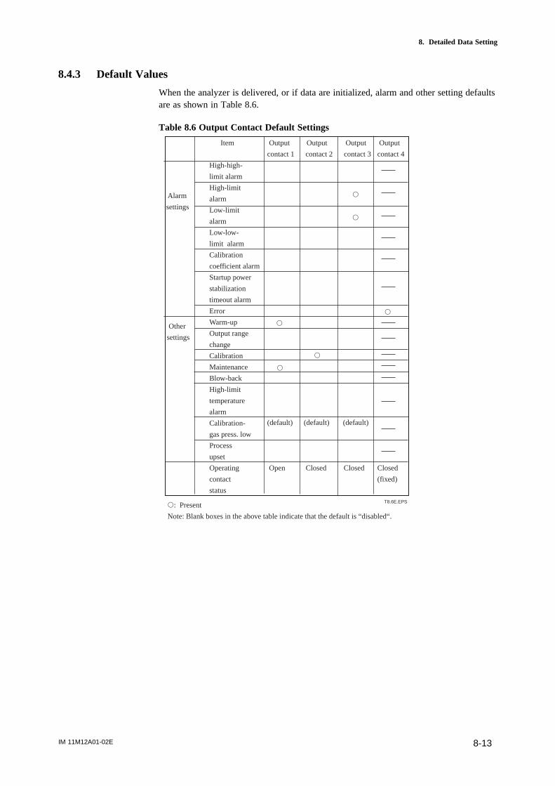
IM 11M12A01-02E 8-13
8. Detailed Data Setting
8.4.3 Default Values
When the analyzer is delivered, or if data are initialized, alarm and other setting defaultsare as shown in Table 8.6.
Table 8.6 Output Contact Default Settings
Alarm
settings
Other
settings
s: Present
Note: Blank boxes in the above table indicate that the default is “disabled“.
s
s
s
s
s
s
T8.6E.EPS
(default) (default) (default)
Item Output Output Output Output
contact 1 contact 2 contact 3 contact 4
High-high-
limit alarm
High-limit
alarm
Low-limit
alarm
Low-low-
limit alarm
Calibration
coefficient alarm
Startup power
stabilization
timeout alarm
Error
Warm-up
Output range
change
Calibration
Maintenance
Blow-back
High-limit
temperature
alarm
Calibration-
gas press. low
Process
upset
Operating Open Closed Closed Closed
contact (fixed)
status
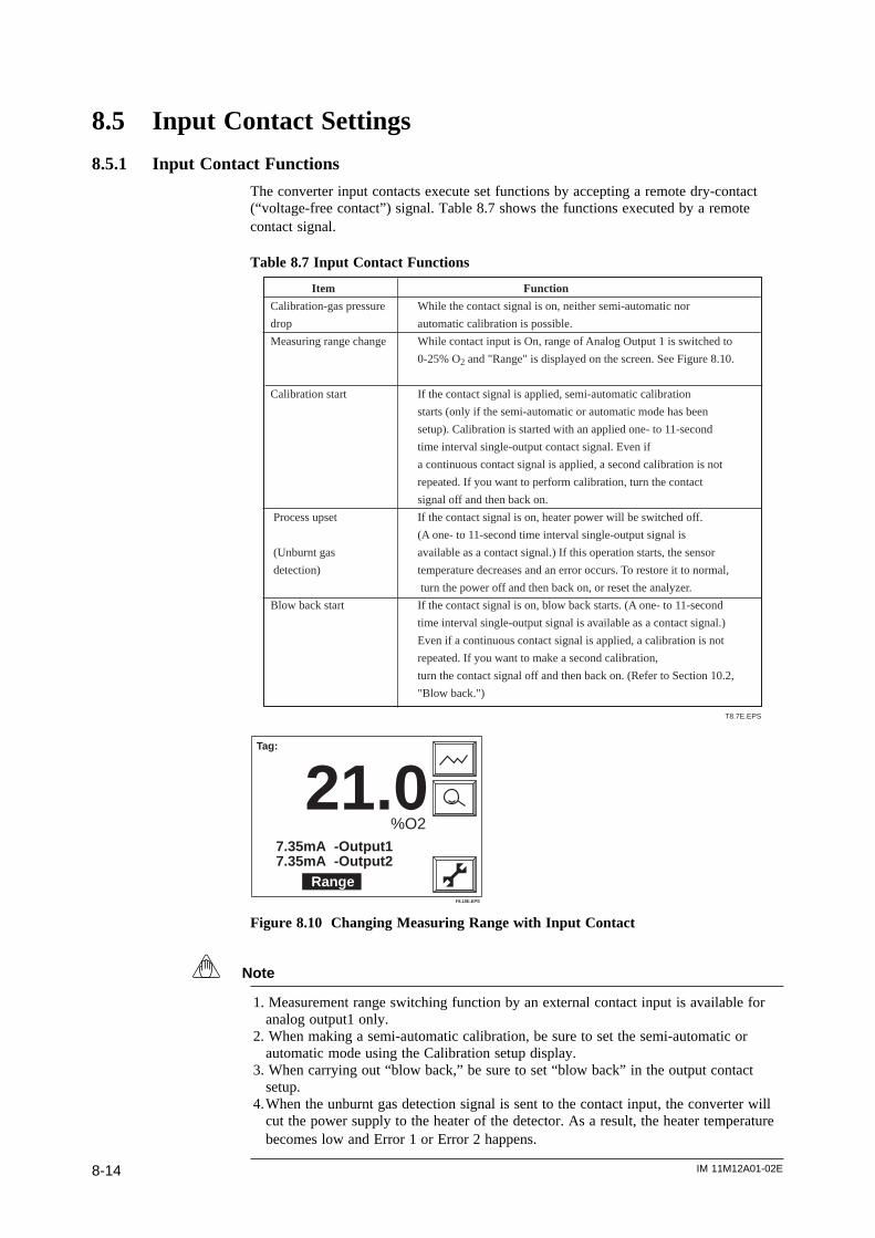
IM 11M12A01-02E8-14
8.5 Input Contact Settings
8.5.1 Input Contact Functions
The converter input contacts execute set functions by accepting a remote dry-contact(“voltage-free contact”) signal. Table 8.7 shows the functions executed by a remotecontact signal.
Table 8.7 Input Contact Functions
Item Function
Calibration-gas pressure While the contact signal is on, neither semi-automatic nor
drop automatic calibration is possible.
Measuring range change While contact input is On, range of Analog Output 1 is switched to
0-25% O2 and "Range" is displayed on the screen. See Figure 8.10.
Calibration start If the contact signal is applied, semi-automatic calibration
starts (only if the semi-automatic or automatic mode has been
setup). Calibration is started with an applied one- to 11-second
time interval single-output contact signal. Even if
a continuous contact signal is applied, a second calibration is not
repeated. If you want to perform calibration, turn the contact
signal off and then back on.
Process upset If the contact signal is on, heater power will be switched off.
(A one- to 11-second time interval single-output signal is
(Unburnt gas available as a contact signal.) If this operation starts, the sensor
detection) temperature decreases and an error occurs. To restore it to normal,
turn the power off and then back on, or reset the analyzer.
Blow back start If the contact signal is on, blow back starts. (A one- to 11-second
time interval single-output signal is available as a contact signal.)
Even if a continuous contact signal is applied, a calibration is not
repeated. If you want to make a second calibration,
turn the contact signal off and then back on. (Refer to Section 10.2,
"Blow back.")
T8.7E.EPS
Tag:
21.0%O2
7.35mA -Output17.35mA -Output2
RangeF8.10E.EPS
Figure 8.10 Changing Measuring Range with Input Contact
Note
1. Measurement range switching function by an external contact input is available foranalog output1 only.
2. When making a semi-automatic calibration, be sure to set the semi-automatic orautomatic mode using the Calibration setup display.
3. When carrying out “blow back,” be sure to set “blow back” in the output contactsetup.
4.When the unburnt gas detection signal is sent to the contact input, the converter willcut the power supply to the heater of the detector. As a result, the heater temperaturebecomes low and Error 1 or Error 2 happens.
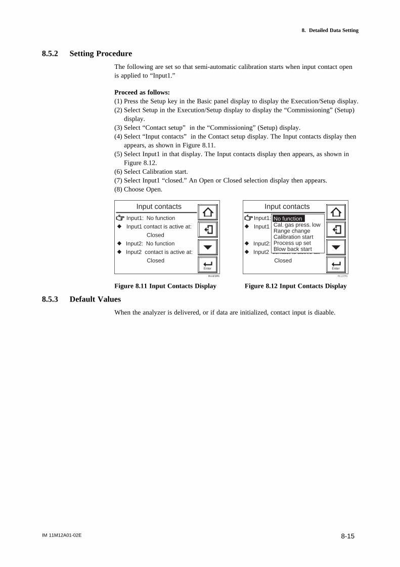
IM 11M12A01-02E 8-15
8. Detailed Data Setting
8.5.2 Setting Procedure
The following are set so that semi-automatic calibration starts when input contact openis applied to “Input1.”
Proceed as follows:(1) Press the Setup key in the Basic panel display to display the Execution/Setup display.(2) Select Setup in the Execution/Setup display to display the “Commissioning” (Setup)
display.(3) Select “Contact setup” in the “Commissioning” (Setup) display.(4) Select “Input contacts” in the Contact setup display. The Input contacts display then
appears, as shown in Figure 8.11.(5) Select Input1 in that display. The Input contacts display then appears, as shown in
Figure 8.12.(6) Select Calibration start.(7) Select Input1 “closed.” An Open or Closed selection display then appears.(8) Choose Open.
Input1: No function
r Input1 contact is active at:
Closed
r Input2: No function
r Input2 contact is active at:
ClosedEnter
Input contacts
F8.11E.EPS
Input1: No function
r Input1 contact is active at:
Closed
r Input2: No function
r Input2 contact is active at:
ClosedEnter
Input contacts
No functionCal. gas press. lowRange changeCalibration startProcess up setBlow back start
F8.12.EPS
Figure 8.11 Input Contacts Display Figure 8.12 Input Contacts Display
8.5.3 Default Values
When the analyzer is delivered, or if data are initialized, contact input is diaable.

IM 11M12A01-02E8-16
8.6 Other Settings
8.6.1 Setting the Date-and-Time
The following describe how to set the date-and-time. Automatic calibration or blowbackworks following this setting.
Proceed as follows:(1) Press the Setup key in the Basic panel display to display the Execution/Setup
display.(2) Select Setup in the Execution/Setup display to display the “Commissioning” (Setup)
display.(3) Select Others in the “Commissioning” (Setup) display. The Others display then
appears, as shown in Figure 8.13.(4) Select Clock. The Clock display then appears, as shown in Figure 8.14.(5) Select Set date to display the numeric-data entry display. To set the date June 21,
2000, enter 2106000 and press the [Enter] key. The display then returns to the oneshown in Figure 8.14.
(5) Select Set time. Enter the time on a 24-hour basis. To enter 2:30 p.m., type in 1430in the numeric-data entry display. Press the [Enter] key, and the time starts at 00second.
Clock
r Averaging
r Fuel setup
r Purging
r Unit setup
r Passwords
r Defaults Enter
Others
F8.13E.EPS
Enter
Set date: 1 3 / 0 7 / 0 0
r Set time: 1 4 : 3 9
1 3 J ul. 2 0 0 0
1 4 : 3 9 : 5 5
Clock
F8.14E.EPS
Figure 8.13 Other Settings Figure 8.14 Clock Display
8.6.2 Setting Periods over which Average Values Are Calculated and Periods overwhich Maximum and Minimum Values Are Monitored
The equipment enables the display of oxygen concentration average values and maxi-mum and minimum values under measurement (see Section 10.1.1, later in this manual).The following section describes how to set the periods over which oxygen concentrationaverage values are calculated and maximum and minimum values are monitored.
8.6.2.1Procedure(1) Press the Setup key in the Basic panel display to display the Execution/Setup
display.(2) Select Setup in the Execution/Setup display to display the Commissioning” (Setup)
display.(3) Select Others in that display and then select Averaging in the Others display. The
averaging display shown in Figure 8.15 then appears.(4) Choose “Set period over which average is calculated” and enter the desired numeric
value from the numeric-data entry display. To enter three hours, type in 003. Theperiod over which average values can be calculated ranges from 1 to 255 hours.
(5) Choose “Set period over which maximum and minimum is stored” and enter thedesired numeric value from the numeric-data entry display. To enter 48 hours, typein 048. The allowable input ranges from 1 to 255 hours.
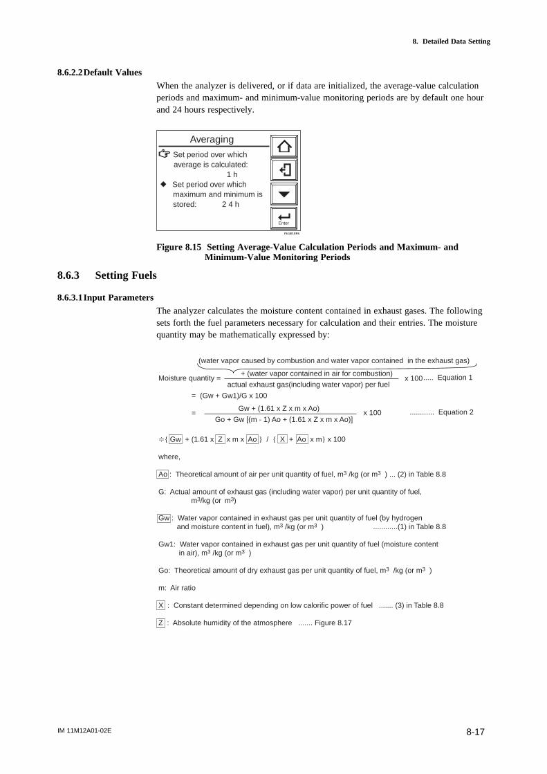
IM 11M12A01-02E 8-17
8. Detailed Data Setting
8.6.2.2Default ValuesWhen the analyzer is delivered, or if data are initialized, the average-value calculationperiods and maximum- and minimum-value monitoring periods are by default one hourand 24 hours respectively.
Set period over which average is calculated: 1 hr Set period over which maximum and minimum is stored: 2 4 h
Enter
Averaging
F8.15E.EPS
Figure 8.15 Setting Average-Value Calculation Periods and Maximum- andMinimum-Value Monitoring Periods
8.6.3 Setting Fuels
8.6.3.1Input ParametersThe analyzer calculates the moisture content contained in exhaust gases. The followingsets forth the fuel parameters necessary for calculation and their entries. The moisturequantity may be mathematically expressed by:
Moisture quantity =
= (Gw + Gw1)/G x 100
=
7 Gw + (1.61 x Z x m x Ao / X + Ao x m x 100
where,
Ao : Theoretical amount of air per unit quantity of fuel, m3 /kg (or m3 ) ... (2) in Table 8.8
G: Actual amount of exhaust gas (including water vapor) per unit quantity of fuel, m3/kg (or m3)
Gw : Water vapor contained in exhaust gas per unit quantity of fuel (by hydrogen and moisture content in fuel), m3 /kg (or m3 ) ............(1) in Table 8.8
Gw1: Water vapor contained in exhaust gas per unit quantity of fuel (moisture content in air), m3 /kg (or m3 )
Go: Theoretical amount of dry exhaust gas per unit quantity of fuel, m3 /kg (or m3 )
m: Air ratio
X : Constant determined depending on low calorific power of fuel ....... (3) in Table 8.8
Z : Absolute humidity of the atmosphere ....... Figure 8.17
(water vapor caused by combustion and water vapor contained in the exhaust gas)
actual exhaust gas(including water vapor) per fuel
+ (water vapor contained in air for combustion) x 100
Gw + (1.61 x Z x m x Ao)
Go + Gw [(m - 1) Ao + (1.61 x Z x m x Ao)]x 100
..... Equation 1
............ Equation 2
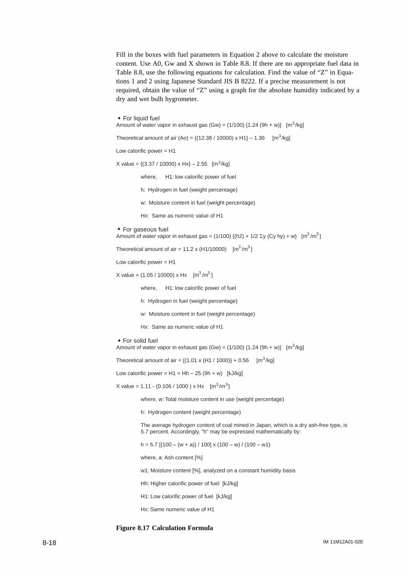
IM 11M12A01-02E8-18
Fill in the boxes with fuel parameters in Equation 2 above to calculate the moisturecontent. Use A0, Gw and X shown in Table 8.8. If there are no appropriate fuel data inTable 8.8, use the following equations for calculation. Find the value of “Z” in Equa-tions 1 and 2 using Japanese Standard JIS B 8222. If a precise measurement is notrequired, obtain the value of “Z” using a graph for the absolute humidity indicated by adry and wet bulb hygrometer.
For liquid fuelAmount of water vapor in exhaust gas (Gw) = (1/100) 1.24 (9h + w) [m /kg]
Theoretical amount of air (Ao) = (12.38 / 10000) x H1 – 1.36 [m /kg]
Low calorific power = H1
X value = (3.37 / 10000) x Hx – 2.55 [m /kg]
where, H1: low calorific power of fuel
h: Hydrogen in fuel (weight percentage)
w: Moisture content in fuel (weight percentage)
Hx: Same as numeric value of H1
For gaseous fuelAmount of water vapor in exhaust gas = (1/100) (h2) + 1/2 Sy (Cy hy) + w [m /m ]
Theoretical amount of air = 11.2 x (H1/10000) [m /m ]
Low calorific power = H1
X value = (1.05 / 10000) x Hx [m /m ]
where, H1: low calorific power of fuel
h: Hydrogen in fuel (weight percentage)
w: Moisture content in fuel (weight percentage)
Hx: Same as numeric value of H1
For solid fuelAmount of water vapor in exhaust gas (Gw) = (1/100) 1.24 (9h + w) [m /kg]
Theoretical amount of air = (1.01 x (H1 / 1000) + 0.56 [m /kg]
Low calorific power = H1 = Hh – 25 (9h + w) [kJ/kg]
X value = 1.11 - (0.106 / 1000 ) x Hx [m /m ]
where, w: Total moisture content in use (weight percentage)
h: Hydrogen content (weight percentage)
The average hydrogen content of coal mined in Japan, which is a dry ash-free type, is 5.7 percent. Accordingly, "h" may be expressed mathematically by:
h = 5.7 [100 – (w + a) / 100] x (100 – w) / (100 – w1)
where, a: Ash content [%]
w1: Moisture content [%], analyzed on a constant humidity basis
Hh: Higher calorific power of fuel [kJ/kg]
H1: Low calorific power of fuel [kJ/kg]
Hx: Same numeric value of H1
3
3
3
3
3
3
3
3
3
3
3
3
3
Figure 8.17 Calculation Formula
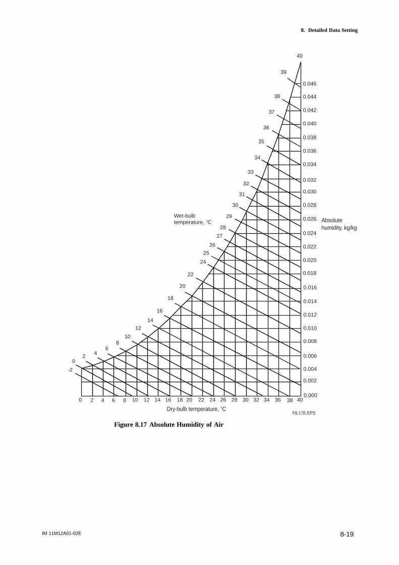
IM 11M12A01-02E 8-19
8. Detailed Data Setting
40
0.046
0.044
0.042
0.040
0.038
0.036
0.034
0.032
0.030
0.028
0.026
0.024
0.022
0.020
0.018
0.016
0.014
0.012
0.010
0.008
0.006
0.004
0.002
0.0000 2 4 6 8 10 12 14 16 18 20 22 24 26 28 30 32 34 36 38 40
-2
02
46
810
12
14
16
18
20
22
24
26
28
30
32
34
36
38
35
37
39
33
31
29
27
25
Wet-bulbtemperature, 8C Absolute
humidity, kg/kg
Dry-bulb temperature, 8CF8.17E.EPS
Figure 8.17 Absolute Humidity of Air
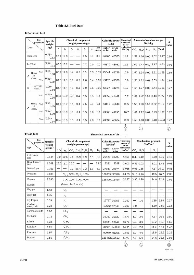
IM 11M12A01-02E8-20
Table 8.8 Fuel Data
d For liquid fuel
A
B
C
C h O N S w CO2 H2O SO2 N2
0.78~ 0.83
0.81~ 0.84
0.85~ 0.88
0.83~ 0.89
0.90~ 0.93
0.93~ 0.95
0.94~ 0.96
0.92~ 1.00
0.94~ 0.97
85.7
85.6
85.9
84.6
84.5
86.1
84.4
86.1
83.0
14.0
13.2
12.0
11.8
11.3
10.9
10.7
10.9
10.5
0.7
0.7
0.4
0.5
0.5
0.5
0.5
0.5
0.5
0.4
0.4
0.4
0.4
0.4
0.5
1.2
0.5
2.0
3.0
1.5
3.5
1.5
3.5
0.0 0.0
0.0 0.0
0.3
0.4
0.5
0.5
0.5
0.6
2.0
0.05
0.05
0.05
0.1
0.1
0.1
0.1
46465
45879
45544
45125
43827
43952
43116
43660
43032
43535
43032
42739
42320
41274
41441
40646
41190
40604
11.4
11.2
10.9
10.8
10.7
10.7
10.5
10.7
10.3
1.59
1.59
1.60
1.58
1.58
1.61
1.58
1.61
1.55
1.56
1.47
1.34
1.32
1.27
1.22
1.20
1.22
1.18
0.00
0.00
0.00
0.01
0.02
0.01
0.02
0.01
0.02
9.02
8.87
8.61
8.53
8.44
8.43
8.32
8.43
8.18
12.17
11.93
11.55
11.44
11.31
11.27
11.12
11.27
10.93
0.96
0.91
0.89
0.86
0.77
0.79
0.72
0.77
0.72
CO H2 CO2 CH4 CmHn O2 N2 CO2 H2O N2
0.544
1.369
0.796
2.030
2.530
1.43
1.25
0.09
1.25
1.96
0.72
1.34
1.25
1.97
2.59
C3H8 90%, C4H10 10%
C3H8 10%, C4H10 90%
O2
N2
H2
CO
CO2
CH4
C2H6
C2H4
C3H8
C4H10
9.0
2.0 88.4 3.2 1.6 4.2
25.0 2.0 20.0 53.0
50.5 25.92.6 3.9 0.1 8.0 20428 18209
3391 3349
37883 34074
102055 93976
125496 115868
12767
12642
39750
69638
62991
99070
128452
10758
12642
35820
63744
59060
91255
118623
4.455
0.603
9.015
24.63
30.37
2.390
2.390
9.570
16.74
14.35
23.91
31.09
0.45
0.45
0.98
3.10
3.90
1.0
2.0
2.0
1.0
3.0
4.0
1.10
0.02
1.88
4.10
4.90
1.0
2.0
3.0
2.0
4.0
5.0
3.60
1.01
7.17
19.5
24.0
1.89
1.89
7.57
13.2
11.4
18.9
24.6
5.15
1.48
10.03
26.7
32.8
2.89
2.89
10.6
18.2
15.4
25.9
33.6
0.46
0.08
0.86
2.36
2.91
0.27
0.32
0.90
1.60
1.48
2.29
2.98
2 1 3
2 1 3
d Gas fuel
Specificweight
kg/l
Chemical component (weight percentage)
Calorific power kJ/kg
Theoretical amount of
air for combustion
Nm3/kg
Amount of combustion gas Nm3/kg
Ash content
Higher order
Lower order
X value
Total
Theoretical amount of air
Combustion product, Nm3/ m3
Calorific power kJ/Nm3
Chemical component (weight percentage)
Specificweight kg/Nm3
Theoretical amount of
air for combustion
Nm3/m3Higher order
Lower order
X value
Kerosene
Light oil
Heavy oil
class 1
Heavy oil class 2
Heavy oil
class 2
No.1
No.2
No.1
No.2
No.3
No.4
Fuelproperties
Type
Coke oven gas
Blast furnace gas
Natural gas
Propane
Butane
(Gases)
Oxygen
Nitrogen
Hydrogen
Carbon monoxide
Carbon dioxide
Methane
Ethane
Ethylene
Propane
Butane
(Molecular Formula)
Fuelproperties
Type
T8.8E.EPS
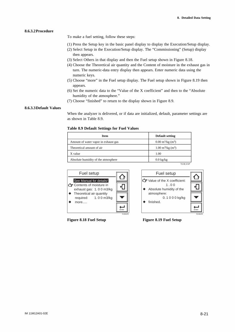
IM 11M12A01-02E 8-21
8. Detailed Data Setting
8.6.3.2ProcedureTo make a fuel setting, follow these steps:
(1) Press the Setup key in the basic panel display to display the Execution/Setup display.(2) Select Setup in the Execution/Setup display. The “Commissioning” (Setup) display
then appears.(3) Select Others in that display and then the Fuel setup shown in Figure 8.18.(4) Choose the Theoretical air quantity and the Content of moisture in the exhaust gas in
turn. The numeric-data entry display then appears. Enter numeric data using thenumeric keys.
(5) Choose “more” in the Fuel setup display. The Fuel setup shown in Figure 8.19 thenappears.
(6) Set the numeric data to the “Value of the X coefficient” and then to the “Absolutehumidity of the atmosphere.”
(7) Choose “finished” to return to the display shown in Figure 8.9.
8.6.3.3Default ValuesWhen the analyzer is delivered, or if data are initialized, default, parameter settings areas shown in Table 8.9.
Table 8.9 Default Settings for Fuel Values
Item Default setting
Amount of water vapor in exhaust gas 0.00 m3/kg (m3)
Theoretical amount of air 1.00 m3/kg (m3)
X value 1.00
Absolute humidity of the atmosphere 0.0 kg/kgT8.9E.ESP
See Manual for details! Contents of moisture in exhaust gas: 1. 0 0 m3/kgr Theoretical air quantity required: 1. 0 0 m3/kgr more.....
Enter
Fuel setup
F8.18E.EPS
Value of the X coefficient: 1 . 0 0 r Absolute humidity of the atmosphere: 0. 1 0 0 0 kg/kgr finished.
Enter
Fuel setup
F8.19E.EPS
Figure 8.18 Fuel Setup Figure 8.19 Fuel Setup
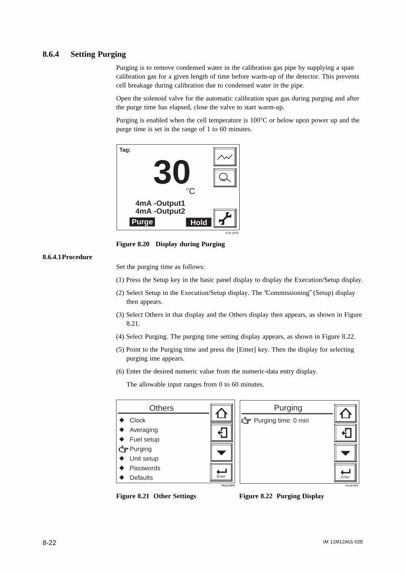
IM 11M12A01-02E8-22
8.6.4 Setting Purging
Purging is to remove condensed water in the calibration gas pipe by supplying a spancalibration gas for a given length of time before warm-up of the detector. This preventscell breakage during calibration due to condensed water in the pipe.
Open the solenoid valve for the automatic calibration span gas during purging and afterthe purge time has elapsed, close the valve to start warm-up.
Purging is enabled when the cell temperature is 1008C or below upon power up and thepurge time is set in the range of 1 to 60 minutes.
Tag:
308C
4mA -Output14mA -Output2
HoldPurgeF20.EPS
Figure 8.20 Display during Purging
8.6.4.1ProcedureSet the purging time as follows:
(1) Press the Setup key in the basic panel display to display the Execution/Setup display.
(2) Select Setup in the Execution/Setup display. The “Commissioning” (Setup) display then appears.
(3) Select Others in that display and the Others display then appears, as shown in Figure 8.21.
(4) Select Purging. The purging time setting display appears, as shown in Figure 8.22.
(5) Point to the Purging time and press the [Enter] key. Then the display for selecting purging ime appears.
(6) Enter the desired numeric value from the numeric-data entry display.
The allowable input ranges from 0 to 60 minutes.
Enter
Others
F8.21.EPS
r Clock
r Averaging
r Fuel setup
Purging
r Unit setup
r Passwords
r Defaults
Enter
Purging time: 0 min
Purging
F8.22E.EPS
Figure 8.21 Other Settings Figure 8.22 Purging Display
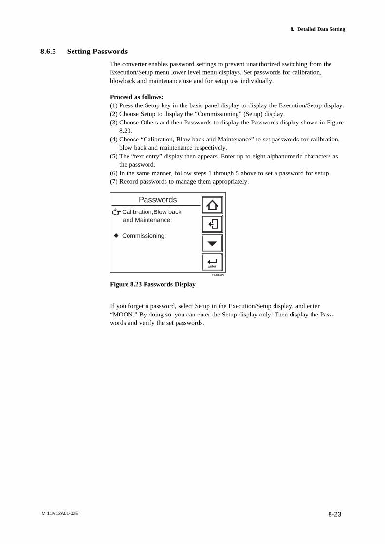
IM 11M12A01-02E 8-23
8. Detailed Data Setting
8.6.5 Setting Passwords
The converter enables password settings to prevent unauthorized switching from theExecution/Setup menu lower level menu displays. Set passwords for calibration,blowback and maintenance use and for setup use individually.
Proceed as follows:(1) Press the Setup key in the basic panel display to display the Execution/Setup display.(2) Choose Setup to display the “Commissioning” (Setup) display.(3) Choose Others and then Passwords to display the Passwords display shown in Figure
8.20.(4) Choose “Calibration, Blow back and Maintenance” to set passwords for calibration,
blow back and maintenance respectively.(5) The “text entry” display then appears. Enter up to eight alphanumeric characters as
the password.(6) In the same manner, follow steps 1 through 5 above to set a password for setup.(7) Record passwords to manage them appropriately.
Enter
Calibration,Blow back and Maintenance:
r Commissioning:
Passwords
F8.23E.EPS
Figure 8.23 Passwords Display
If you forget a password, select Setup in the Execution/Setup display, and enter“MOON.” By doing so, you can enter the Setup display only. Then display the Pass-words and verify the set passwords.

IM 11M12A01-02E8-24

IM 11M12A01-02E 9-1
9. Calibration
9. Calibration
9.1 Calibration Briefs
9.1.1 Principle of Measurement
This section sets forth the principles of measurement with a zirconia oxygen analyzerbefore detailing calibration.
A solid electrolyte such as zirconia allows the conductivity of oxygen ions at hightemperatures. Therefore, when a zirconia-plated element with platinum electrodes onboth sides is heated up in contact with gases having different partial-oxygen pressures oneach side, the element shows the action of the concentration cell. In other words, theelectrode in contact with a gas with a higher partial-oxygen pressure acts as a negativeelectrode. As the gas comes in contact with the zirconia element in this negativeelectrode, oxygen molecules in the gas acquire electrons and become ions. Moving inthe zirconia element, they eventually arrive at the positive electrode on the opposite side.There, the electrons are released and the ions return to the oxygen molecules. Thisreaction is indicated as follows:
Negative electrode: O2 + 4e 2 O 2-
Positive electrode: 2 O 2- O2 + 4 e
The electromotive force E (mV) between the two electrodes, generated by the reaction,is governed by Nernst’s equation as follows:
E = -RT/nF ln PX/PA........................................Equation (1)
where, R: Gas constant
T: Absolute temperature
n: 4
F: Faraday’s constant
Px: Oxygen concentration in a gas in contact with the positivezirconia electrode (%)
Pa: Oxygen concentration in a gas in contact with the negativezirconia electrode (%)
Assuming the zirconia element is heated up to 7508C, then we obtain equation (1)above.
E = log PxPa
................................. Equation (2)250.74
With this analyzer, the sensor (zirconia element) is heated up to 7508C, so Equation (2)is valid. At that point, the relationship as in Figure 9.1 is effected between the oxygenconcentration of the measurement gas in contact with the positive electrode and theelectromotive force of the sensor (= cell), where a comparison gas of air is used on thenegative electrode side.

IM 11M12A01-02E9-2
0.1 0.5 1 5 10 21.0 50 100
120
100
80
60
40
20
0
-20
-40
0.51% 02,81.92mV(Zero origin of calibration)
21.0% O2, 0mV(Span origin of calibration)
Oxygen concentration (vol %)
Cellvoltage(mV)
F9.1E.EPS
Figure 9.1 Oxygen concentration in a Measurement Gas vs Cell Voltage (21% O2
Equivalent)
The measurement principles of a zirconia oxygen analyzer have been described above.However, the relationship between oxygen concentration and the electromotive force ofa cell is only theoretical. Usually, in practice, a sensor shows a slight deviation from thetheoretical value. This is the reason why calibration is necessary. To meet this require-ment, an analyzer calibration is conducted so that a calibration curve is obtained, whichcorrects the deviation from the theoretical cell electromotive force.
9.1.2 Calibration Gas
A gas with a known oxygen concentration is used for calibration. Normal calibration isperformed using two different gases: a zero gas of low oxygen concentration and a spangas of high oxygen concentration. In some cases, only one of the gases needs to be usedfor calibration. However, even if only one of the gases is normally used, calibrationusing both gases should be done at least once.
The zero gas normally used has an oxygen concentration of 0.95 to 1.0 vol%O2 with a
balance of nitrogen gas (N2). The span gas widely used is clean air (at a dew-point
temperature below -208C and free of oily mist or dust, as in instrument air).
For best accuracy, as the span gas use oxygen whose concentration is near the top of themeasurement range, in a nitrogen mixture.
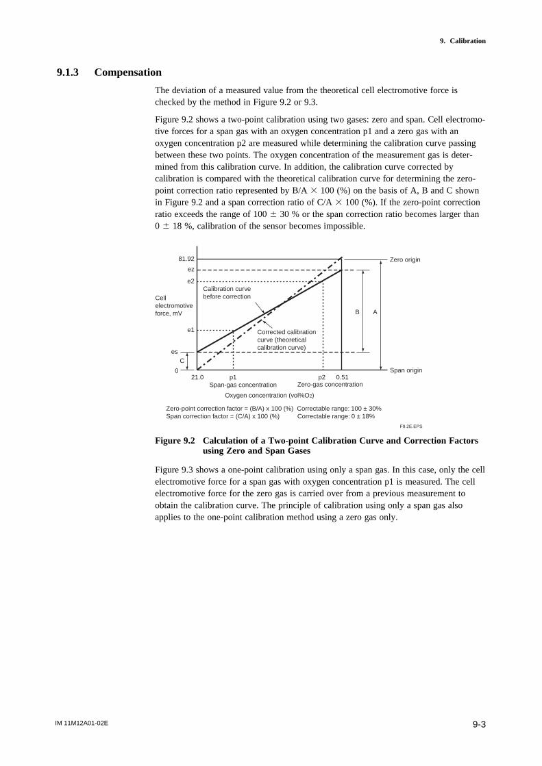
IM 11M12A01-02E 9-3
9. Calibration
9.1.3 Compensation
The deviation of a measured value from the theoretical cell electromotive force ischecked by the method in Figure 9.2 or 9.3.
Figure 9.2 shows a two-point calibration using two gases: zero and span. Cell electromo-tive forces for a span gas with an oxygen concentration p1 and a zero gas with anoxygen concentration p2 are measured while determining the calibration curve passingbetween these two points. The oxygen concentration of the measurement gas is deter-mined from this calibration curve. In addition, the calibration curve corrected bycalibration is compared with the theoretical calibration curve for determining the zero-point correction ratio represented by B/A 3 100 (%) on the basis of A, B and C shownin Figure 9.2 and a span correction ratio of C/A 3 100 (%). If the zero-point correctionratio exceeds the range of 100 6 30 % or the span correction ratio becomes larger than0 6 18 %, calibration of the sensor becomes impossible.
21.0 p1 p2 0.51
81.92
ez
e2
e1
es
0
C
AB
Zero-point correction factor = (B/A) x 100 (%) Correctable range: 100 ± 30%Span correction factor = (C/A) x 100 (%) Correctable range: 0 ± 18%
Cell electromotive force, mV
Calibration curve before correction
Corrected calibration curve (theoretical calibration curve)
Zero origin
Span-gas concentration Zero-gas concentration
Span origin
Oxygen concentration (vol%O2)
F9.2E.EPS
Figure 9.2 Calculation of a Two-point Calibration Curve and Correction Factorsusing Zero and Span Gases
Figure 9.3 shows a one-point calibration using only a span gas. In this case, only the cellelectromotive force for a span gas with oxygen concentration p1 is measured. The cellelectromotive force for the zero gas is carried over from a previous measurement toobtain the calibration curve. The principle of calibration using only a span gas alsoapplies to the one-point calibration method using a zero gas only.
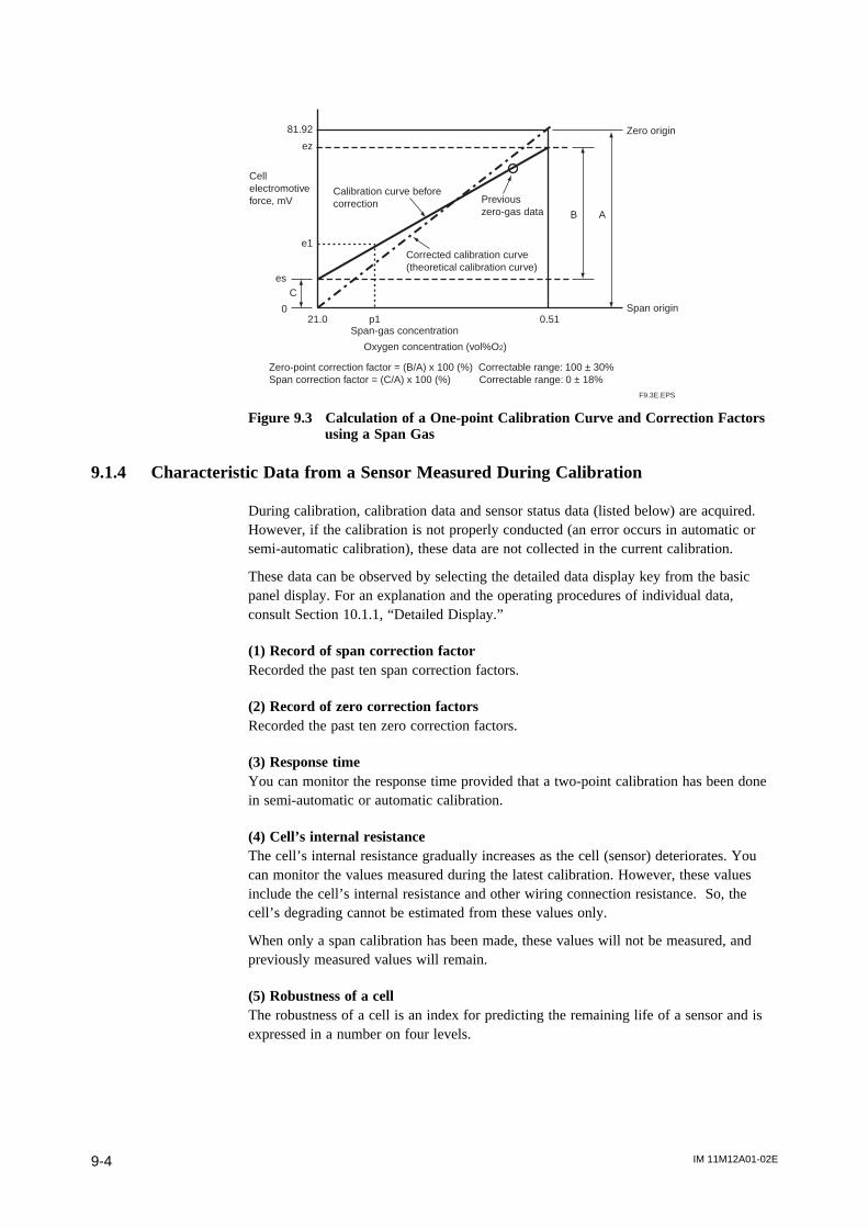
IM 11M12A01-02E9-4
21.0 p1 0.51
81.92
ez
e1
es
0
C
AB
Zero-point correction factor = (B/A) x 100 (%) Correctable range: 100 ± 30%Span correction factor = (C/A) x 100 (%) Correctable range: 0 ± 18%
Cell electromotive force, mV
Calibration curve before correction Previous
zero-gas data
Corrected calibration curve(theoretical calibration curve)
Zero origin
Span origin
Span-gas concentration
Oxygen concentration (vol%O2)
F9.3E.EPS
Figure 9.3 Calculation of a One-point Calibration Curve and Correction Factorsusing a Span Gas
9.1.4 Characteristic Data from a Sensor Measured During Calibration
During calibration, calibration data and sensor status data (listed below) are acquired.However, if the calibration is not properly conducted (an error occurs in automatic orsemi-automatic calibration), these data are not collected in the current calibration.
These data can be observed by selecting the detailed data display key from the basicpanel display. For an explanation and the operating procedures of individual data,consult Section 10.1.1, “Detailed Display.”
(1) Record of span correction factorRecorded the past ten span correction factors.
(2) Record of zero correction factorsRecorded the past ten zero correction factors.
(3) Response timeYou can monitor the response time provided that a two-point calibration has been donein semi-automatic or automatic calibration.
(4) Cell’s internal resistanceThe cell’s internal resistance gradually increases as the cell (sensor) deteriorates. Youcan monitor the values measured during the latest calibration. However, these valuesinclude the cell’s internal resistance and other wiring connection resistance. So, thecell’s degrading cannot be estimated from these values only.
When only a span calibration has been made, these values will not be measured, andpreviously measured values will remain.
(5) Robustness of a cellThe robustness of a cell is an index for predicting the remaining life of a sensor and isexpressed in a number on four levels.
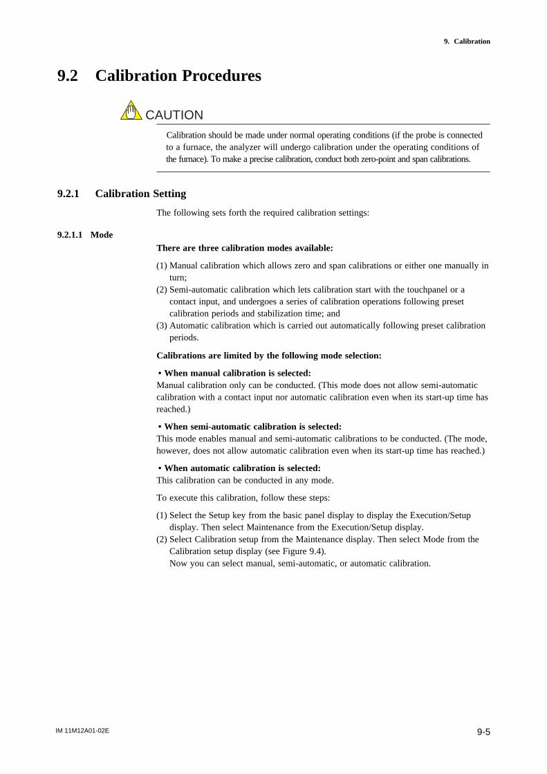
IM 11M12A01-02E 9-5
9. Calibration
9.2 Calibration Procedures
CAUTION
Calibration should be made under normal operating conditions (if the probe is connectedto a furnace, the analyzer will undergo calibration under the operating conditions ofthe furnace). To make a precise calibration, conduct both zero-point and span calibrations.
9.2.1 Calibration Setting
The following sets forth the required calibration settings:
9.2.1.1 ModeThere are three calibration modes available:
(1) Manual calibration which allows zero and span calibrations or either one manually inturn;
(2) Semi-automatic calibration which lets calibration start with the touchpanel or acontact input, and undergoes a series of calibration operations following presetcalibration periods and stabilization time; and
(3) Automatic calibration which is carried out automatically following preset calibrationperiods.
Calibrations are limited by the following mode selection:
• When manual calibration is selected:Manual calibration only can be conducted. (This mode does not allow semi-automaticcalibration with a contact input nor automatic calibration even when its start-up time hasreached.)
• When semi-automatic calibration is selected:This mode enables manual and semi-automatic calibrations to be conducted. (The mode,however, does not allow automatic calibration even when its start-up time has reached.)
• When automatic calibration is selected:This calibration can be conducted in any mode.
To execute this calibration, follow these steps:
(1) Select the Setup key from the basic panel display to display the Execution/Setupdisplay. Then select Maintenance from the Execution/Setup display.
(2) Select Calibration setup from the Maintenance display. Then select Mode from theCalibration setup display (see Figure 9.4).Now you can select manual, semi-automatic, or automatic calibration.
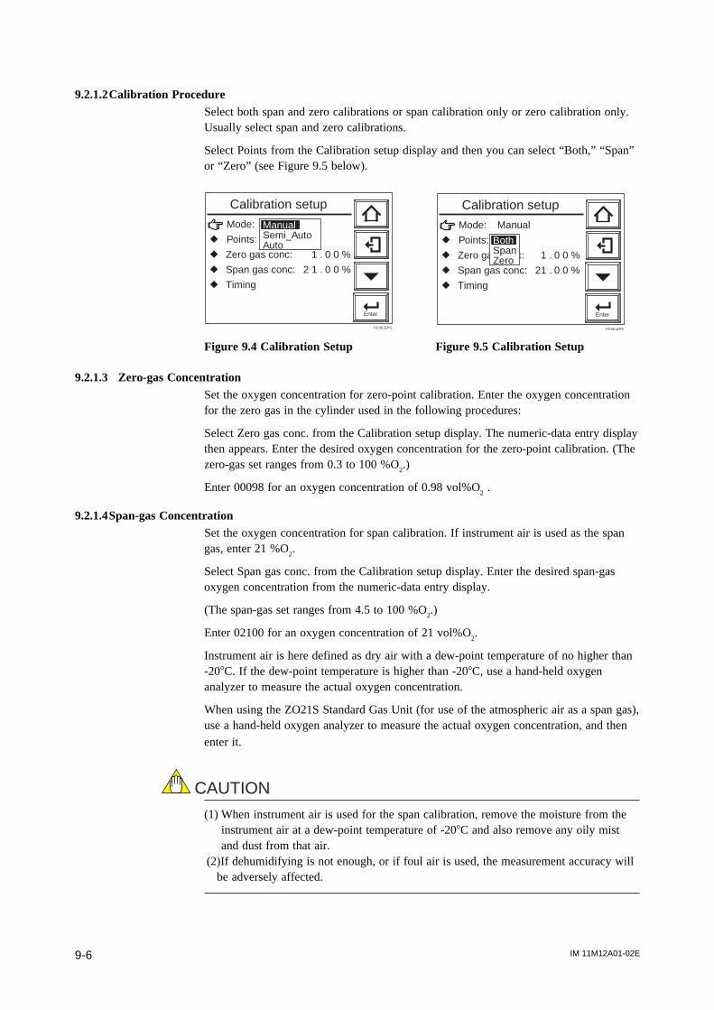
IM 11M12A01-02E9-6
9.2.1.2Calibration ProcedureSelect both span and zero calibrations or span calibration only or zero calibration only.Usually select span and zero calibrations.
Select Points from the Calibration setup display and then you can select “Both,” “Span”or “Zero” (see Figure 9.5 below).
Mode:
r Points:
r Zero gas conc: 1 . 0 0 %
r Span gas conc: 2 1 . 0 0 %
r Timing
Enter
ManualSemi_AutoAuto
Calibration setup
F9.4E.EPS
Mode: Manual
r Points:
r Zero gas conc: 1 . 0 0 %
r Span gas conc: 21 . 0 0 %
r Timing
Enter
BothSpanZero
Calibration setup
F9.5E.EPS
Figure 9.4 Calibration Setup Figure 9.5 Calibration Setup
9.2.1.3 Zero-gas ConcentrationSet the oxygen concentration for zero-point calibration. Enter the oxygen concentrationfor the zero gas in the cylinder used in the following procedures:
Select Zero gas conc. from the Calibration setup display. The numeric-data entry displaythen appears. Enter the desired oxygen concentration for the zero-point calibration. (Thezero-gas set ranges from 0.3 to 100 %O
2.)
Enter 00098 for an oxygen concentration of 0.98 vol%O2 .
9.2.1.4Span-gas ConcentrationSet the oxygen concentration for span calibration. If instrument air is used as the spangas, enter 21 %O
2.
Select Span gas conc. from the Calibration setup display. Enter the desired span-gasoxygen concentration from the numeric-data entry display.
(The span-gas set ranges from 4.5 to 100 %O2.)
Enter 02100 for an oxygen concentration of 21 vol%O2.
Instrument air is here defined as dry air with a dew-point temperature of no higher than-208C. If the dew-point temperature is higher than -208C, use a hand-held oxygenanalyzer to measure the actual oxygen concentration.
When using the ZO21S Standard Gas Unit (for use of the atmospheric air as a span gas),use a hand-held oxygen analyzer to measure the actual oxygen concentration, and thenenter it.
CAUTION
(1) When instrument air is used for the span calibration, remove the moisture from theinstrument air at a dew-point temperature of -208C and also remove any oily mistand dust from that air.
(2)If dehumidifying is not enough, or if foul air is used, the measurement accuracy willbe adversely affected.
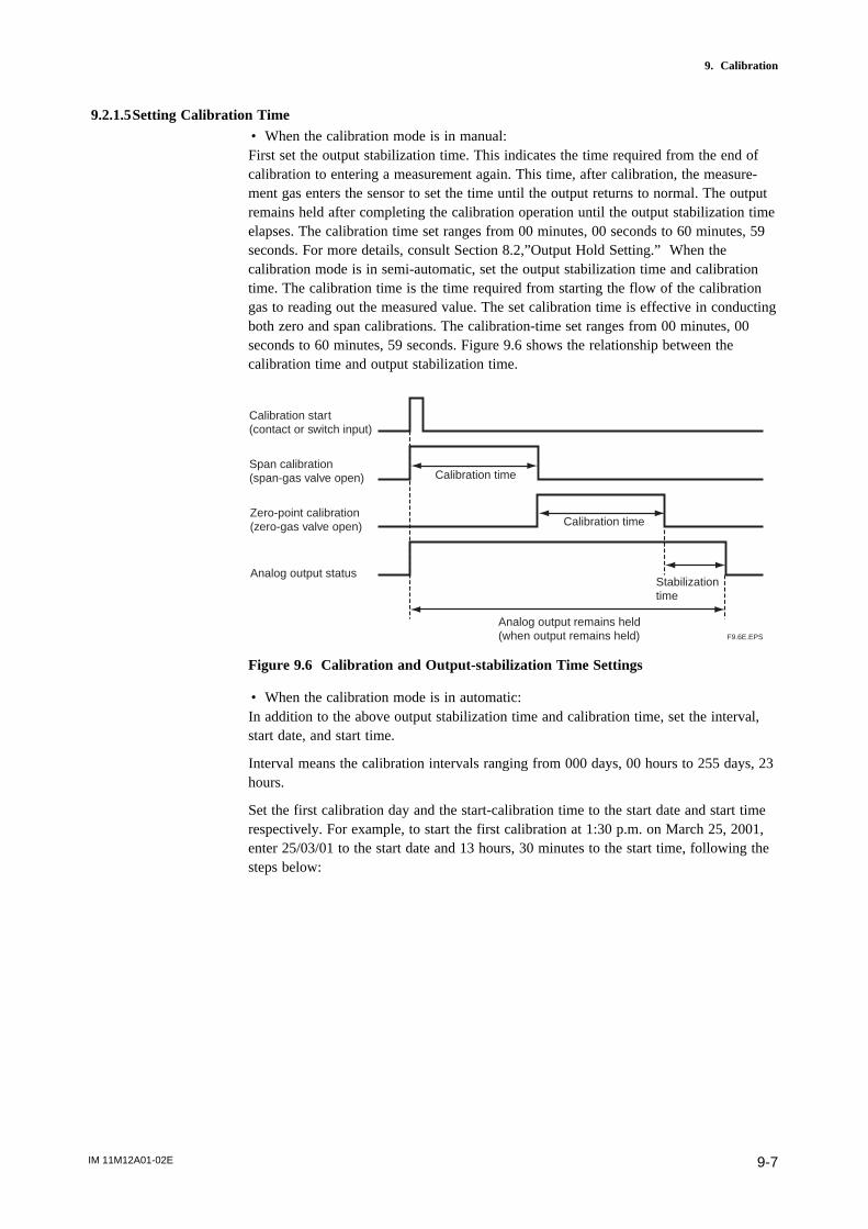
IM 11M12A01-02E 9-7
9. Calibration
9.2.1.5Setting Calibration Time• When the calibration mode is in manual:First set the output stabilization time. This indicates the time required from the end ofcalibration to entering a measurement again. This time, after calibration, the measure-ment gas enters the sensor to set the time until the output returns to normal. The outputremains held after completing the calibration operation until the output stabilization timeelapses. The calibration time set ranges from 00 minutes, 00 seconds to 60 minutes, 59seconds. For more details, consult Section 8.2,”Output Hold Setting.” When thecalibration mode is in semi-automatic, set the output stabilization time and calibrationtime. The calibration time is the time required from starting the flow of the calibrationgas to reading out the measured value. The set calibration time is effective in conductingboth zero and span calibrations. The calibration-time set ranges from 00 minutes, 00seconds to 60 minutes, 59 seconds. Figure 9.6 shows the relationship between thecalibration time and output stabilization time.
Analog output remains held(when output remains held)
Calibration start (contact or switch input)
Span calibration (span-gas valve open)
Zero-point calibration (zero-gas valve open)
Analog output status
Calibration time
Calibration time
Stabilization time
F9.6E.EPS
Figure 9.6 Calibration and Output-stabilization Time Settings
• When the calibration mode is in automatic:In addition to the above output stabilization time and calibration time, set the interval,start date, and start time.
Interval means the calibration intervals ranging from 000 days, 00 hours to 255 days, 23hours.
Set the first calibration day and the start-calibration time to the start date and start timerespectively. For example, to start the first calibration at 1:30 p.m. on March 25, 2001,enter 25/03/01 to the start date and 13 hours, 30 minutes to the start time, following thesteps below:

IM 11M12A01-02E9-8
(1) Select the “Calibration timing” display. A panel display as shown in Figure 9.7appears.
(2) Select each item for the calibration to display the numeric-data entry display. Enterthe desired numeric values for the calibration.
Enter
Hold time: 1 0 min 0 0 s
r Csl time: 1 0 min 0 0 s
r lnterval: 3 0 d 0 0 h
r Start date: 0 1 / 0 1 / 0 0
r Start time: 0 0 : 0 0
Calibration timing
F9.7E.EPS
Figure 9.7 “Calibration Timing” Display
When setting calibration timing requirements, bear the following precautions in mind:
(1) If the calibration interval is shorter than the sum of stabilization time plus calibrationtime, the second calibration start time will conflict with the first calibration. In such acase, the second calibration will not be conducted. (When both zero and spancalibrations are to be performed, the calibration time is double that required for asingle (zero or span) calibration.)
(2) For the same reason, if the calibration start time conflicts with manual calibration orsemi-automatic calibration, the current calibration will not be conducted.
(3) If the calibration time conflicts with maintenance service or blowback operations,calibration will start after completing the maintenance service or blowback opera-tions (see Section 8.2.1, earlier in this manual).
(4) If 000 days, 00 hours are set for the calibration intervals, only the first calibrationwill be conducted; a second or later calibration will not be conducted.
(5) If a past date is set to the calibration start day, no calibration will be conducted.
9.2.2 Default Values
When the analyzer is delivered, or if data are initialized, the calibration settings are bydefault, as shown in Table 9.1.
Table 9.1 Default Settings for Calibration
Item Default Setting
Calibration mode Manual
Calibration procedure Span - zero
Zero-gas (oxygen) 1.00% concentration
Span-gas (oxygen) concentration 21.00%
Output hold (stabilization) time 10 minutes, 00 seconds
Calibration time 10 minutes, 00 seconds
Calibration interval 30 days, 00 hours
Start day 01 / 01 / 00
Start time 00:00
Manual Calibration
Semi-automatic Calibration
Automatic Calibration
T9.1E.EPS

IM 11M12A01-02E 9-9
9. Calibration
9.2.3 Calibration
9.2.3.1Manual Calibration
For manual calibration, consult Section 7.12, “Calibration,” earlier in this manual.
9.2.3.2Semi-automatic CalibrationTo start calibration, follow these steps:
(1) Press the Setup key in the basic panel display to display the Execution/Setup display.Then select Calibration from the Execution/Setup display. The Calibration displayshown in Figure 9.8 appears.
(2) Select Semi-auto calibration to display the Semi-automatic calibration display shownin Figure 9.9.
(3) Select Start calibration. The display shown in Figure 9.10 appears, and then startcalibration.
Enter
Manual calibrationr Semi-auto calibration
Calibration
F9.8E.EPS
Check settings Zero gas conc: 1 . 0 0 % Span gas conc: 2 1 . 0 0 % Cal time: 1 0 min 0 0 sGo to setup to change value. Start calibrationr Cancel calibration
Enter
Semi-auto calibration
F9.9E.EPS
Figure 9.8 Calibration Display Figure 9.9 Semi-automatic Calibration Display
2 1 . 0 0%0.5min./div
1 . 0 0%
2 1 . 0 % O2 CAL. TIME
Semi-auto calibration
F9.10E.EPS
Figure 9.10 Semi-automatic Calibration Display
To start calibration using an input contact, follow these steps:
(1) Make sure that Calibration start has been selected in the Input contacts display (seeSection 8.5, earlier in this manual).
(2) Apply an input contact to start calibration.
To stop calibration midway, follow these steps:(1) Press the Return key. If this key is pressed midway during calibration, the calibration
will stop and the output stabilization time will be set up.(2) Press the Return key once again to return to the basic panel display and the analyzer
will be in normal measurement.

IM 11M12A01-02E9-10
9.2.3.3Automatic CalibrationNo execution operations are required for automatic calibration. Automatic calibrationstarts in accordance with a preset start day and time. Calibration is then executed at
preset intervals.
CAUTION
Before conducting a semi-automatic or automatic calibration, run the automatic calibra-tion unit beforehand to obtain a calibration flow of 600 ± 60 ml/min.
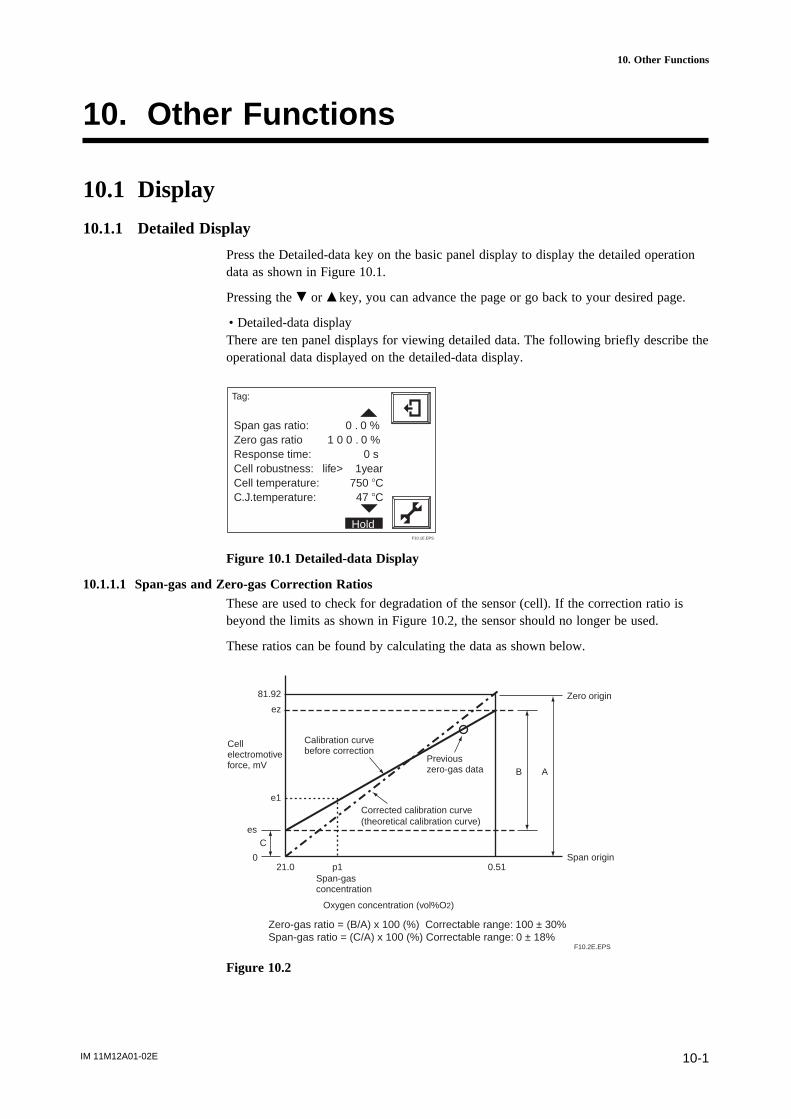
IM 11M12A01-02E 10-1
10. Other Functions
10. Other Functions
10.1 Display
10.1.1 Detailed Display
Press the Detailed-data key on the basic panel display to display the detailed operationdata as shown in Figure 10.1.
Pressing the . or m key, you can advance the page or go back to your desired page.
• Detailed-data displayThere are ten panel displays for viewing detailed data. The following briefly describe theoperational data displayed on the detailed-data display.
Span gas ratio: 0 . 0 %Zero gas ratio 1 0 0 . 0 % Response time: 0 sCell robustness: life> 1yearCell temperature: 750 8CC.J.temperature: 47 8C
Tag:
HoldF10.1E.EPS
Figure 10.1 Detailed-data Display
10.1.1.1 Span-gas and Zero-gas Correction RatiosThese are used to check for degradation of the sensor (cell). If the correction ratio isbeyond the limits as shown in Figure 10.2, the sensor should no longer be used.
These ratios can be found by calculating the data as shown below.
21.0 p1 0.51
81.92
ez
e1
es
0
C
AB
Zero-gas ratio = (B/A) x 100 (%) Correctable range: 100 ± 30%Span-gas ratio = (C/A) x 100 (%) Correctable range: 0 ± 18%
Cell electromotive force, mV
Calibration curve before correction
Previous zero-gas data
Corrected calibration curve (theoretical calibration curve)
Zero origin
Span origin
Span-gas concentration
Oxygen concentration (vol%O2)
F10.2E.EPS
Figure 10.2

IM 11M12A01-02E10-2
10.1.1.2 Response TimeThe cell’s response time is obtained in the procedure shown in Figure 10.3. If onlyeither a zero-point or span calibration has been carried out, the response time will not bemeasured just as it will not be measured in manual calibration.
mA
90%100%
The response time is obtained after the corrected calibration curve has been found. The response time is calculated, starting at the point corresponding to 10% of the analog output up to the point at 90% of the analog output span. That is, this response time is a 10 to 90% response.
10% of analog output span
Five minutes maximum
Response time
Start calibrationTime
Calibration complete
F10.3E.EPS
Figure 10.3 Functional Drawing of Response Time
10.1.1.3 Robustness of a CellThe robustness of a cell is an index for predicting the remaining life of a sensor and isexpressed as one of four time periods during which the cell may still be used:
(1) more than a year(2) more than six months(3) more than three months(4) less than one month
The above four time periods are tentative and only used for preventive maintenance, notfor warranty of the performance.
This cell’s robustness can be found by a total evaluation of data involving the responsetime, the cell’s internal resistance, and calibration factor. However, if a zero or spancalibration was not made, the response time cannot be measured. In such a case, thecell’s robustness is found except for the response time.
10.1.1.4 Cell TemperatureThis indicates the cell (sensor) temperature, usually indicating 7508 C., obtainable fromthe thermoelectromotive force and cold junction temperature described below.
10.1.1.5 C. J. TemperatureThis indicates the detector terminal box temperature, which compensates for the coldjunction temperature for a thermocouple measuring the cell temperature. When the ZR22Detector is used, the maximum C. J. temperature will be 1508 C. If the terminal boxtemperature exceeds this, take measures, for example, so that the terminal box is notexposed to radiation to reduce that temperature.
The maximum C. J. temperature varies depending on the type of detector.
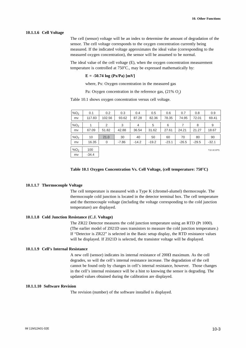
IM 11M12A01-02E 10-3
10. Other Functions
10.1.1.6 Cell VoltageThe cell (sensor) voltage will be an index to determine the amount of degradation of thesensor. The cell voltage corresponds to the oxygen concentration currently beingmeasured. If the indicated voltage approximates the ideal value (corresponding to themeasured oxygen concentration), the sensor will be assumed to be normal.
The ideal value of the cell voltage (E), when the oxygen concentration measurementtemperature is controlled at 7508C., may be expressed mathematically by:
E = -50.74 log (Px/Pa) [mV]
where, Px: Oxygen concentration in the measured gas
Pa: Oxygen concentration in the reference gas, (21% O2)
Table 10.1 shows oxygen concentration versus cell voltage.
%O2 0.1 0.2 0.3 0.4 0.5 0.6 0.7 0.8 0.9
mv 117.83 102.56 93.62 87.28 82.36 78.35 74.95 72.01 69.41
%O2 1 2 3 4 5 6 7 8 9
mv 67.09 51.82 42.88 36.54 31.62 27.61 24.21 21.27 18.67
%O2 10 21.0 30 40 50 60 70 80 90
mv 16.35 0 -7.86 -14.2 -19.2 -23.1 -26.5 -29.5 -32.1
%O2 100
mv -34.4
T10.1E.EPS
Table 10.1 Oxygen Concentration Vs. Cell Voltage, (cell temperature: 7508C)
10.1.1.7 Thermocouple VoltageThe cell temperature is measured with a Type K (chromel-alumel) thermocouple. Thethermocouple cold junction is located in the detector terminal box. The cell temperatureand the thermocouple voltage (including the voltage corresponding to the cold junctiontemperature) are displayed.
10.1.1.8 Cold Junction Resistance (C.J. Voltage)The ZR22 Detector measures the cold junction temperature using an RTD (Pt 1000).(The earlier model of Z021D uses transistors to measure the cold junction temperature.)If “Detector is ZR22” is selected in the Basic setup display, the RTD resistance valueswill be displayed. If Z021D is selected, the transistor voltage will be displayed.
10.1.1.9 Cell’s Internal ResistanceA new cell (sensor) indicates its internal resistance of 200V maximum. As the celldegrades, so will the cell’s internal resistance increase. The degradation of the cellcannot be found only by changes in cell’s internal resistance, however. Those changesin the cell’s internal resistance will be a hint to knowing the sensor is degrading. Theupdated values obtained during the calibration are displayed.
10.1.1.10 Software RevisionThe revision (number) of the software installed is displayed.
IM 11M12A01-02E10-4
10.1.1.11 Maximum Oxygen ConcentrationThe maximum oxygen concentration and the time of its occurrence during the periodspecified in the Averaging display are displayed. If the setup period elapses, the maxi-mum oxygen concentration that has been displayed so far will be cleared and a newmaximum oxygen concentration will be displayed. If the setup period of time ischanged, the current maximum oxygen concentration will be displayed (for more details,see Section 8.6.2 earlier in this manual).
10.1.1.12 Minimum Oxygen ConcentrationThe minimum oxygen concentration and the time of its occurrence during the periodspecified in the Averaging display are displayed. If the setup period elapses, the mini-mum oxygen concentration that has been displayed so far will be cleared and a newminimum oxygen concentration will be displayed. If the setup period of time is changed,the current minimum oxygen concentration will be displayed (for more details, seeSection 8.6.2 earlier in this manual).
10.1.1.13 Average Oxygen ConcentrationThe average oxygen concentration during the periods over which average values arecalculated is displayed. If the setup period elapses, the average oxygen concentrationthat has been displayed so far will be cleared and a new average oxygen concentrationwill be displayed. If the setup period of time is changed, the current average oxygenconcentration will be displayed (for more details, see Section 8.6.2 earlier in thismanual).
10.1.1.14 Heater On-Time RatioThe probe sensor is heated to and maintained at 7508 C. When the measured gas tem-perature is high, the amount of heater ON-time decreases.
10.1.1.15 TimeThe current date and time are displayed. These are backed up with built-in batteries, sono adjustment is required after the power is switched off.
10.1.1.1.16 History of Calibration TimeThe calibration-conducted dates and times, and span-gas and zero-gas ratios for the pastten calibrations are stored in memory.
10.1.1.17 Power Supply VoltageFor the temperature control for the heater of the detector to work best, you should setthe power supply voltage and frequency appropriately, as the control parameters arebased on this. Set the AC supply voltage to "Low" if supply is 140 V AC or less, and to"High" if it is 180 V or more.
10.1.1.18 Power FrequencySet the AC supply frequency setting appropriately --"Low" for 50Hz, and "High" for60Hz.

IM 11M12A01-02E 10-5
10. Other Functions
10.1.2 Trend Graph
Press the Graph display key in the basic panel display to switch to the graph display.This will help grasp the measured-value trend. Touching anywhere on the graph displaywill return to the basic panel display. To set the trend graph display, follow the steps inSection 10.1.2.1.
10.1.2.1 Setting Display Items(1) Press the Setup key in the Basic panel display to display the Execution/Setup display.
Select Maintenance from the Execution/Setup display.(2) Select Display setup from the Maintenance display.(3) Select Trend graph from the Display setup display. The Trend graph display shown
in Figure 10.4 appears.(4) Select “Parameter: Oxygen” from the Trend graph display. Then select the desired
display item shown in Table 10.2.
Table 10.2 Trend Graph Display Items
Selected item Description Oxygen concentration Oxygen concentration graph under measurement Output 1 If this equipment is for the oxygen analyzer, the trend graph
will be an oxygen concentration graph. Output 2 If this equipment is for the oxygen analyzer, the trend graph
will be an oxygen concentration graph.T10.2E.EPS
Enter
Parameter: Oxygenr Sample interval: 3 0 s Scale Oxygen r Upper limit: 2 5 . 0 % O2r Lower limit: 0 . 0 % O2
Trend graph
F10.4E.EPS
Figure 10.4 Trend Graph
10.1.2.2 Sampling PeriodTo plot a graph, set the sampling period for the measurement data.
This graph allows the plotting of 60 data items on one graduation on the time axis. So, ifyou set a ten-second sampling period, one graduation corresponds to 600 seconds(Figure 10.5). The allowable sampling periods range from 1 to 30 seconds. If you set aone-second sampling period, the axis of the abscissas then corresponds to five minutes.If you set it to 30 seconds, the axis of the abscissas then corresponds to 150 minutes.

IM 11M12A01-02E10-6
0.0%O2
25.0%O2 10min./div
12.3%O2
60 data items
Upper limit set
Lower limit set
Time per graduation, calculated by the set sampling period
Currently measured value
Sampling period F10.5E.EPS
Figure 10.5 Plotting Graph for Sampling Period
10.1.2.3 Setting Upper and Lower Limit Values on GraphSet upper- and lower-limit values on the graph in the following procedure:
Press Upper limit in the Trend graph display. The numeric-data entry key appears. Enterthe upper-limit value. Also enter the lower-limit value in the same way. The allowablesettings for both upper-limit and lower-limit values range from 0 to 100 %O
2.
10.1.2.4 Default SettingWhen the analyzer is delivered, or if data are initialized, the set data are by default, asshown in Table 10.3.
Table 10.3 Default Values for Graph Setting
Item Default Value
Parameter Oxygen concentration
Sampling period 30 seconds
Upper limit 25%O2
Lower limit 0%O2
T10.3E.EPS
CAUTION
If a rapid change in the measured value occurs during sampling, no sampled data areplotted on the graph. Use the graph indication tentatively. Check the output current foraccurate data.
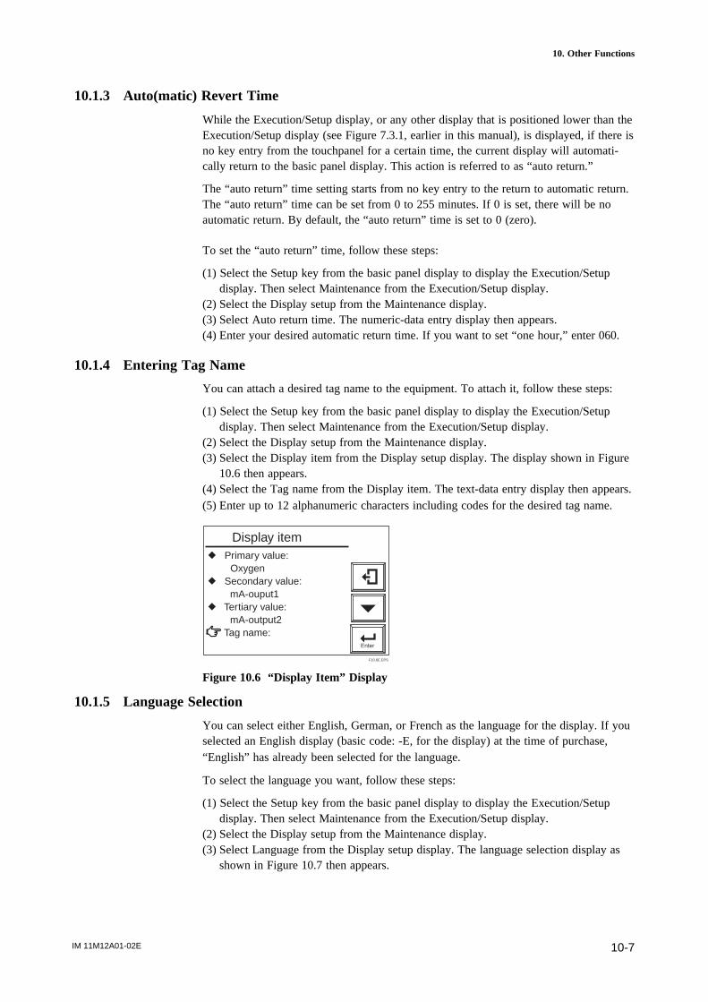
IM 11M12A01-02E 10-7
10. Other Functions
10.1.3 Auto(matic) Revert Time
While the Execution/Setup display, or any other display that is positioned lower than theExecution/Setup display (see Figure 7.3.1, earlier in this manual), is displayed, if there isno key entry from the touchpanel for a certain time, the current display will automati-cally return to the basic panel display. This action is referred to as “auto return.”
The “auto return” time setting starts from no key entry to the return to automatic return.The “auto return” time can be set from 0 to 255 minutes. If 0 is set, there will be noautomatic return. By default, the “auto return” time is set to 0 (zero).
To set the “auto return” time, follow these steps:
(1) Select the Setup key from the basic panel display to display the Execution/Setupdisplay. Then select Maintenance from the Execution/Setup display.
(2) Select the Display setup from the Maintenance display.(3) Select Auto return time. The numeric-data entry display then appears.(4) Enter your desired automatic return time. If you want to set “one hour,” enter 060.
10.1.4 Entering Tag Name
You can attach a desired tag name to the equipment. To attach it, follow these steps:
(1) Select the Setup key from the basic panel display to display the Execution/Setupdisplay. Then select Maintenance from the Execution/Setup display.
(2) Select the Display setup from the Maintenance display.(3) Select the Display item from the Display setup display. The display shown in Figure
10.6 then appears.(4) Select the Tag name from the Display item. The text-data entry display then appears.(5) Enter up to 12 alphanumeric characters including codes for the desired tag name.
Enter
r Primary value: Oxygenr Secondary value: mA-ouput1r Tertiary value: mA-output2 Tag name:
Display item
F10.6E.EPS
Figure 10.6 “Display Item” Display
10.1.5 Language Selection
You can select either English, German, or French as the language for the display. If youselected an English display (basic code: -E, for the display) at the time of purchase,“English” has already been selected for the language.
To select the language you want, follow these steps:
(1) Select the Setup key from the basic panel display to display the Execution/Setupdisplay. Then select Maintenance from the Execution/Setup display.
(2) Select the Display setup from the Maintenance display.(3) Select Language from the Display setup display. The language selection display as
shown in Figure 10.7 then appears.

IM 11M12A01-02E10-8
Enter
r Display itemr Trend graphr Auto return time: 0 min Language:
Display setup
F10.7E.EPS
EnglishDeutschFrancias
Figure 10.7 Display Setup Display
10.2 Blow back
10.2.1 Blow back Setup
The following sections describe the blow back setup procedures required for carryingout blow back.
10.2.1.1 ModeThere are three blow back modes available:
(1) No function – blow back disabled.(2) Semi-automatic – in this mode, touchpanel operations or contact input signals will
start and perform blow back operations according to a preset time and outputstabilization time.
(3) Automatic – performs blow back operations automatically according to a presetinterval.
These three modes each have the specific limitations described below:
• If “No Function” is selectedNo blow back operations are executed.
• If “Semi-auto” is selected, semi-automatic blow back can be executed (but nocalibration is made even when the automatic calibration startup time is reached.)
• If “Auto” is selected, automatic blow back can be executed in either the “Auto” or“Semi-auto” mode.
To select the desired mode, follow these steps:
(1) Select the Setup key from the basic panel display to display the Execution/Setupdisplay. Then select Maintenance from the Execution/Setup display.
(2) Select the Blow back setup from the Maintenance display and select Mode. Themode selection display as shown in Figure 10.8 then appears.
Enter
No functionSemi_AutoAuto
Mode:
Blow back setup
F10.9E.EPS
Figure 10.8 Blow back Setup Display
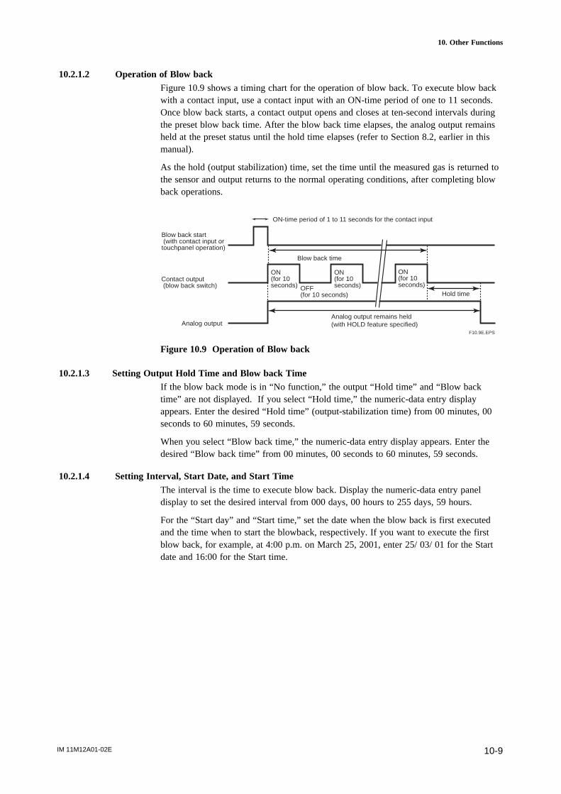
IM 11M12A01-02E 10-9
10. Other Functions
10.2.1.2 Operation of Blow backFigure 10.9 shows a timing chart for the operation of blow back. To execute blow backwith a contact input, use a contact input with an ON-time period of one to 11 seconds.Once blow back starts, a contact output opens and closes at ten-second intervals duringthe preset blow back time. After the blow back time elapses, the analog output remainsheld at the preset status until the hold time elapses (refer to Section 8.2, earlier in thismanual).
As the hold (output stabilization) time, set the time until the measured gas is returned tothe sensor and output returns to the normal operating conditions, after completing blowback operations.
Analog output remains held (with HOLD feature specified)
ON-time period of 1 to 11 seconds for the contact input
Blow back start (with contact input or touchpanel operation)
Blow back time
Contact output (blow back switch)
ON (for 10 seconds)
ON (for 10 seconds)OFF
(for 10 seconds)
Analog output
Hold time
ON (for 10 seconds)
F10.9E.EPS
Figure 10.9 Operation of Blow back
10.2.1.3 Setting Output Hold Time and Blow back TimeIf the blow back mode is in “No function,” the output “Hold time” and “Blow backtime” are not displayed. If you select “Hold time,” the numeric-data entry displayappears. Enter the desired “Hold time” (output-stabilization time) from 00 minutes, 00seconds to 60 minutes, 59 seconds.
When you select “Blow back time,” the numeric-data entry display appears. Enter thedesired “Blow back time” from 00 minutes, 00 seconds to 60 minutes, 59 seconds.
10.2.1.4 Setting Interval, Start Date, and Start TimeThe interval is the time to execute blow back. Display the numeric-data entry paneldisplay to set the desired interval from 000 days, 00 hours to 255 days, 59 hours.
For the “Start day” and “Start time,” set the date when the blow back is first executedand the time when to start the blowback, respectively. If you want to execute the firstblow back, for example, at 4:00 p.m. on March 25, 2001, enter 25/ 03/ 01 for the Startdate and 16:00 for the Start time.

IM 11M12A01-02E10-10
Mode: Autor Hold time: 1 0 min 0 0 sr Blow back time: 1 0 min 0 0 sr Interval: 3 0 d 0 0 hr Start date: 0 1 / 0 1 / 0 0r Start tine: 0 0 : 0 0
Enter
Blow back setup
F10.10E.EPS
Figure 10.10 Blow back Setup Display
In the Blow back setup display shown in Figure 10.10, if you choose “Mode: Nofunction” or “Semi-auto blow back,” the Interval, Start Date, and Start Time for theseare not displayed.
CAUTION
• If the blow back is executed with an input contact, it must be preset in the Inputcontacts setting (for more details, see Section 8.5, earlier in this manual).
• In Section 8.4, “Output Contact Setup,” earlier in this manual, set the contact used asthe blow back switch beforehand.
• Do not set any other function for the contact used as the blow back switch. Other-wise, blow back may be activated when the contact is closed by any other function.
• No blow back is executed during calibration or maintenance service. If automaticblow back reaches the preset start time during calibration or maintenance service,blow back will be executed after completing the calibration or maintenance serviceand after the equipment returns to the measurement mode.
• If automatic blow back reaches the preset start time during semi-automatic blow back,the current automatic blow back will not be executed.
• If you set the blow back interval at 000 days, 00 hours, only the first blow back isthen executed. No subsequent blow backs will be executed.
• If a past date is set for the Start time, no blow back will be executed.
10.2.1.5 Default SettingWhen the analyzer is delivered, or if data are initialized, the blow back settings are bydefault, as shown in Table 10.4.
Table 10.4 Blow back Default Setting
Item Default setting
Mode No function ("invalid")
Hold time 10 minutes, 00 seconds
Blow-back time 10 minutes, 00 seconds
Interval 30 days, 00 hours
Start date 01/ 01/00
Start time 00:00T10.4E.EPS
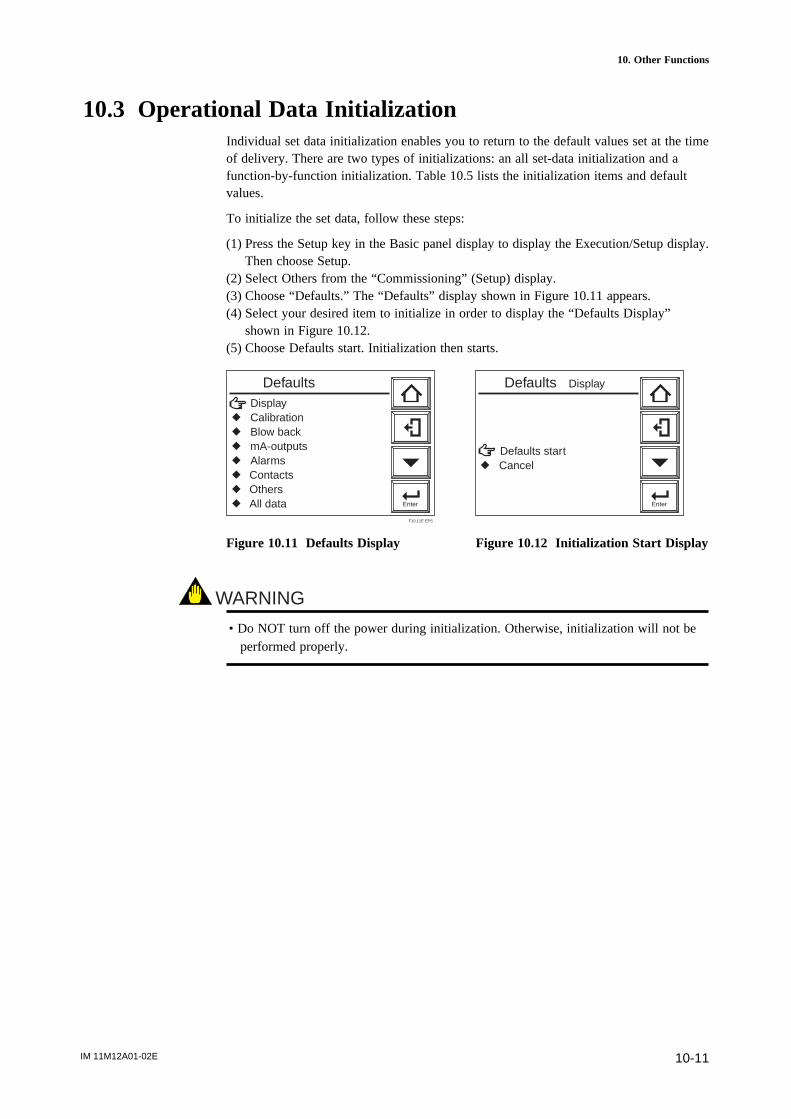
IM 11M12A01-02E 10-11
10. Other Functions
10.3 Operational Data InitializationIndividual set data initialization enables you to return to the default values set at the timeof delivery. There are two types of initializations: an all set-data initialization and afunction-by-function initialization. Table 10.5 lists the initialization items and defaultvalues.
To initialize the set data, follow these steps:
(1) Press the Setup key in the Basic panel display to display the Execution/Setup display.Then choose Setup.
(2) Select Others from the “Commissioning” (Setup) display.(3) Choose “Defaults.” The “Defaults” display shown in Figure 10.11 appears.(4) Select your desired item to initialize in order to display the “Defaults Display”
shown in Figure 10.12.(5) Choose Defaults start. Initialization then starts.
Displayr Calibrationr Blow backr mA-outputsr Alarmsr Contactsr Othersr All data Enter
Defaults
F10.11E.EPS
Enter
Defaults startr Cancel
Defaults Display
Figure 10.11 Defaults Display Figure 10.12 Initialization Start Display
WARNING
• Do NOT turn off the power during initialization. Otherwise, initialization will not beperformed properly.
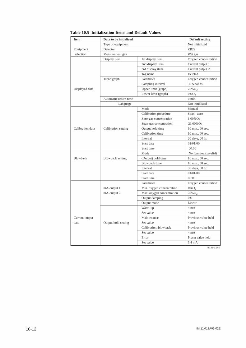
IM 11M12A01-02E10-12
Table 10.5 Initialization Items and Default Values
T10.5E-1.EPS
Item Data to be initialized Default setting
Type of equipment Not initialized
Equipment Detector ZR22
selection Measurement gas Wet gas
Display item 1st display item Oxygen concentration
2nd display item Current output 1
3rd display item Current output 2
Tag name Deleted
Trend graph Parameter Oxygen concentration
Sampling interval 30 seconds
Displayed data Upper limit (graph) 25%O2
Lower limit (graph) 0%O2
Automatic return time 0 min.
Language Not initialized
Mode Manual
Calibration procedure Span - zero
Zero-gas concentration 1.00%O2
Span-gas concentration 21.00%O2
Calibration data Calibration setting Output hold time 10 min., 00 sec.
Calibration time 10 min., 00 sec.
Interval 30 days, 00 hr.
Start date 01/01/00
Start time 00:00
Mode No function (invalid)
Blowback Blowback setting (Output) hold time 10 min., 00 sec.
Blowback time 10 min., 00 sec.
Interval 30 days, 00 hr.
Start date 01/01/00
Start time 00:00
Parameter Oxygen concentration
mA-output 1 Min. oxygen concentration 0%O2
mA-output 2 Max. oxygen concentration 25%O2
Output damping 0%
Output mode Linear
Warm-up 4 mA
Set value 4 mA
Current output Maintenance Previous value held
data Output hold setting Set value 4 mA
Calibration, blowback Previous value held
Set value 4 mA
Error Preset value held
Set value 3.4 mA
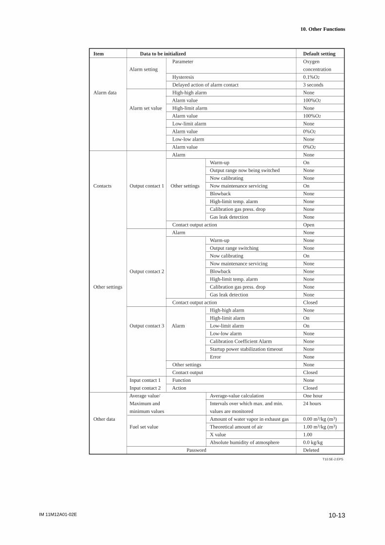
IM 11M12A01-02E 10-13
10. Other Functions
T10.5E-2.EPS
Item Data to be initialized Default setting
Parameter Oxygen
Alarm setting concentration
Hysteresis 0.1%O2
Delayed action of alarm contact 3 seconds
Alarm data High-high alarm None
Alarm value 100%O2
Alarm set value High-limit alarm None
Alarm value 100%O2
Low-limit alarm None
Alarm value 0%O2
Low-low alarm None
Alarm value 0%O2
Alarm None
Warm-up On
Output range now being switched None
Now calibrating None
Contacts Output contact 1 Other settings Now maintenance servicing On
Blowback None
High-limit temp. alarm None
Calibration gas press. drop None
Gas leak detection None
Contact output action Open
Alarm None
Warm-up None
Output range switching None
Now calibrating On
Now maintenance servicing None
Output contact 2 Blowback None
High-limit temp. alarm None
Other settings Calibration gas press. drop None
Gas leak detection None
Contact output action Closed
High-high alarm None
High-limit alarm On
Output contact 3 Alarm Low-limit alarm On
Low-low alarm None
Calibration Coefficient Alarm None
Startup power stabilization timeout None
Error None
Other settings None
Contact output Closed
Input contact 1 Function None
Input contact 2 Action Closed
Average value/ Average-value calculation One hour
Maximum and Intervals over which max. and min. 24 hours
minimum values values are monitored
Other data Amount of water vapor in exhaust gas 0.00 m3/kg (m3)
Fuel set value Theoretical amount of air 1.00 m3/kg (m3)
X value 1.00
Absolute humidity of atmosphere 0.0 kg/kg
Password Deleted
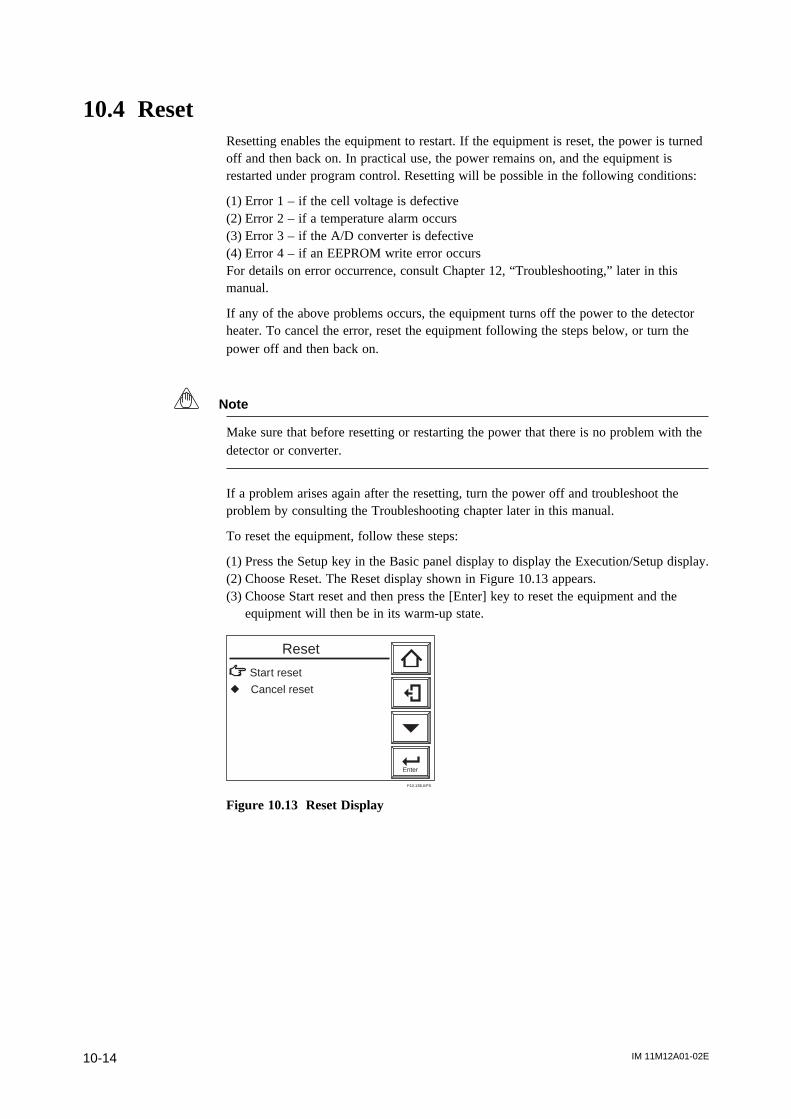
IM 11M12A01-02E10-14
10.4 ResetResetting enables the equipment to restart. If the equipment is reset, the power is turnedoff and then back on. In practical use, the power remains on, and the equipment isrestarted under program control. Resetting will be possible in the following conditions:
(1) Error 1 – if the cell voltage is defective(2) Error 2 – if a temperature alarm occurs(3) Error 3 – if the A/D converter is defective(4) Error 4 – if an EEPROM write error occursFor details on error occurrence, consult Chapter 12, “Troubleshooting,” later in thismanual.
If any of the above problems occurs, the equipment turns off the power to the detectorheater. To cancel the error, reset the equipment following the steps below, or turn thepower off and then back on.
Note
Make sure that before resetting or restarting the power that there is no problem with thedetector or converter.
If a problem arises again after the resetting, turn the power off and troubleshoot theproblem by consulting the Troubleshooting chapter later in this manual.
To reset the equipment, follow these steps:
(1) Press the Setup key in the Basic panel display to display the Execution/Setup display.(2) Choose Reset. The Reset display shown in Figure 10.13 appears.(3) Choose Start reset and then press the [Enter] key to reset the equipment and the
equipment will then be in its warm-up state.
Enter
Start reset
r Cancel reset
Reset
F10.13E.EPS
Figure 10.13 Reset Display
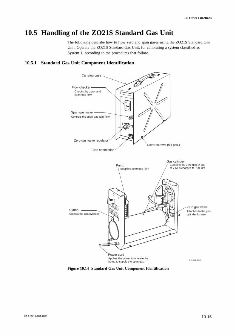
IM 11M12A01-02E 10-15
10. Other Functions
10.5 Handling of the ZO21S Standard Gas UnitThe following describe how to flow zero and span gases using the ZO21S Standard GasUnit. Operate the ZO21S Standard Gas Unit, for calibrating a system classified asSystem 1, according to the procedures that follow.
10.5.1 Standard Gas Unit Component Identification
Applies the power to operate the pump to supply the span gas.
Carrying case
Flow checker
Span gas valve
Checks the zero- and span-gas flow.
Controls the span-gas (air) flow.
Zero gas valve regulator
Tube connection
Cover screws (six pcs.)
PumpSupplies span gas (air)
Gas cylinderContains the zero gas. A gas of 7 Nl is charged to 700 kPa
ClampClamps the gas cylinder.
Zero gas valveAttaches to the gas cylinder for use.
Power cord
F10.14E.EPS
Figure 10.14 Standard Gas Unit Component Identification

IM 11M12A01-02E10-16
10.5.2 Installing Gas Cylinders
Each ZO21S Standard Gas Unit comes with six zero-gas cylinders including a spare.Each gas cylinder contains 7-liters of gas with a 0.95 to 1.0 vol% O
2 (concentration
varies with each cylinder) and nitrogen, at a pressure of 700 kgPaG (at 358 C).
The operating details and handling precautions are also printed on the product. Pleaseread them beforehand.
To install the gas cylinder, follow these steps:
(1) Attach the zero gas valves onto the gas cylinder. First, turn the valve regulator ofthe zero gas valves counterclockwise to completely retract the needle at the top fromthe gasket surface. Maintaining the valve in this position, screw the valve mountinginto the mouthpiece of the gas cylinder. (If screw connection is proper, you can turnthe screw manually. Do not use any tool.) When the gasket comes in contact with themouthpiece of the gas cylinder and you can no longer turn it manually, tighten thelock nut with a wrench.
(2) Remove the carrying case from the standard gas unit. The case is attached to theunit with six screws. So, loosen the screws and lift them off.
(3) Slide the gas cylinder through the hole in the back of the unit and connect the tube(the piping in the unit) to the valve connections. Insert each tube at least 10 mm toprevent leakage, and secure it using a tube clamp.
(4) Attach the gas cylinder to the case. Extend the valve regulator of the zero gas valvesthrough the hole in the front panel of the unit and secure the bottom of the cylinderwith the clamp.
(5) Take note of the oxygen concentration of the sealed gas indicated on the gascylinder and replace the carrying case. Enter the oxygen concentration of the sealedgas, following instructions on the converter display. Also check that no piping isdisconnected.
Thus, the work of installing a gas cylinder is completed. However, gases in the cylinderscannot immediately flow out after these procedures. To discharge the gases, it isnecessary for the needle in the zero gas valves to puncture a hole in the gas cylinder (seeSection 10.5.3).
10.5.3 Calibration Gas Flow
<Preparation before calibration>(1) To operate the standard gas unit, place it on a nearly horizontal surface in order to
allow the flow check to indicate the precise flow rate. In addition, a power supply fordriving the span gas (air) supply pump is required near the unit (the length of thepower cord attached to the unit is 2 m). Select a suitable location for the unit nearthe installation site of the converter.
(2) Connect the tube connector port of the standard gas unit to the calibration gas inletof the detector, using a polyethylene resin tube with an outside diameter of 6 mm. Becareful to prevent gas leakage.
(3) Fully open the needle valve mounted on the calibration gas inlet of the detector.(4) Enter the oxygen concentration of the sealed gas (noted from the cylinder) into the
converter. Also check that the oxygen concentration of the span gas is correctly set(21 vol% O
2 for clean air). When using the ZO21S Standard Gas Unit (for use of the
atmospheric air as a span gas), use a hand-held oxygen analyzer to measure theactual oxygen concentration, and then enter it.

IM 11M12A01-02E 10-17
10. Other Functions
<Flow of span gas (air)>The standard gas unit is used only when manual calibration is employed. Therefore, thetiming for flowing span gas (air) is included in the manual calibration flowchart de-scribed in Section 10.5.2. For operation of the converter, see Section 7.12, earlier in thismanual.
(1) When the message “Open span gas valve” is displayed on the converter displayduring calibration, plug the power cord into the power supply socket to start thepump of the standard gas unit.
Enter
Open span gas valve.
Set flow span gas to
600ml/min.
Valve opened
r Cancel calibration
Manual calibration
F10.15E.EPS
Figure 10.15 Manual Calibration Display
(2) Next, adjust the flow rate to 600 ± 60 ml/min using the span gas valve “AIR” (theflow check ball stops floating on the green line when the valve is slowly opened). Torotate the valve shaft, loosen the lock nut and turn it using a flat-blade screwdriver.Turning the valve shaft counterclockwise increases the flow rate.
(3) After adjusting the flow rate, tighten the valve lock nut.(4) Select Valve opened (to start calibration) from the Manual calibration display shown
in Figure 10.15. Check the Trend graph display to see that the measured value isstabilized. Then press the [Enter] key. The Manual calibration display shown inFigure 10.16 appears. Disconnect the power cord to stop the pump.
Enter
Span calibration
Close the span gas valve.
Zero calibration
r End
Manual calibration
F10.16E.EPS
Figure 10.16 Manual Calibration Display
<Flow of zero gas>Cause a zero gas to flow according to the Manual calibration display shown in Figure10.17.
Enter
Open zero gas valve.
Set flow span gas to
600ml/min.
Valve opened
r Cancel calibration
Manual calibration
F10.17E.EPS
Figure 10.17 Manual Calibration Display

IM 11M12A01-02E10-18
(1) Use the needle of the zero gas valve “ CHECK GAS “ to puncture a hole in the gascylinder installed as described in Section 10.5.2. Fully clockwise turn the valveregulator by hand.
(2) Next, adjust the flow rate to 600 ± 60 ml/min (the flow check ball stops floating onthe green line when the valve is slowly opened). Turn the regulator of the zero-gasvalves back slowly counterclockwise. At that time, the flow rate also decreases as theinner pressure of the gas cylinder decreases. Therefore, monitor the flow check and,when the ball’s position changes greatly, readjust the valve.
(3) Select Valve opened (to start calibration) from the Manual calibration display. Checkthe Trend graph display to see that the measured value is stabilized. Then press the[Enter] key. The Manual calibration display shown in Figure 10.18 appears. Thenstop the zero-gas flow immediately. Turn the zero-gas valve regulator fully clock-wise. If this valve regulator is not properly adjusted, the needle valve will not closecompletely and a cylinder gas may leak.
Enter
Zero calibration
Close the zero gas valve.
Span calibration
r End
Manual calibration
F10.18E.EPS
Figure 10.18 Zero-gas Calibration Complete (in Manual Calibration Display)
Note
Be sure not to terminate a calibration in progress because of a shortage of gas in thecylinder. Each gas cylinder is operable for nine minutes or more provided the gas isdischarged at the specified rate. Therefore, if your calibration time is estimated at fourminutes, you can operate the zero-point calibration twice.
<Treatment after completion of calibration>(1) Fully close the needle valve mounted on the calibration gas inlet of the detector.
(2) Remove the tube connecting the detector to the standard gas unit.
WARNING
Store the standard gas unit with the gas cylinder mounted where the ambient tempera-ture does not exceed 408 C. Otherwise, the gas cylinder may explode. Store the spare gascylinders under the same condition.
IM 11M12A01-02E 10-19
10. Other Functions
10.6 Methods of Operating Valves in the ZA8F Flow SettingUnit
The ZA8F Flow Setting Unit is used as a calibration device for a system conforming toSystem 2. Calibration in such a system is to be manually operated. So, you have tooperate the valve of the Flow Setting each time calibration is made (starting and stop-ping the calibration gas flow and adjusting the flow rate). This applies even if you areusing the ZR40H Autocaliration Unit. For operation of the converter, see Section 7.12,earlier in this manual.
10.6.1 Preparation Before Calibration
To operate the ZA8F Flow Setting Unit, prepare for calibration as follows:
(1) Check for a complete closing of the zero gas flow setting valve in the unit and openthe regulator valve for the zero gas cylinder until the secondary pressure equalsmeasured gas pressure + approx 50 kPa (or measured gas pressure plus approx. 150kPa when a check valve is used, maximum pressure rating is 300 kPa).
(2) Check that the oxygen concentration of the zero gas and span gas (instrument air 21vol% O
2) in the cylinder is set in the converter.
10.6.2 Operating the Span Gas Flow Setting Valve
The following description is given assuming that instrument air, the same as the refer-ence gas, is used as the span gas.
(1) When the display shown in Figure 10.15 appears during calibration, open the spangas flow setting valve of the flow setting unit and adjust the flow rate to 600 ± 60ml/min. Turn the valve slowly counterclockwise after loosening the lock nut if thevalve has a lock nut. To check the flow rate, use the calibration flow meter. If themeasurement gas pressure is extremely high, adjust the measurement gas pressure toobtain pressures (listed in Table 10.6) ± 10%.
Table 10.6
Measurement gas pressure (kPa) 50 100 150 200 250
Flowrate (ml/min) 500 430 380 250 320T10.6E.EPS
(2) Adjust the flow rate and select Valve opened from the Manual calibration display.Check the Trend graph display to see that the measured value is stabilized. Thenpress the [Enter] key. The Manual calibration display shown in Figure 10.16 appears.
(3) Close the span gas flow setting valve to stop the span gas (air) flow. If the valve hasa lock nut, be sure to tighten the lock nut to prevent any leakage of span gas into the
sensor during measurement.
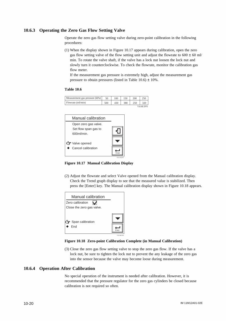
IM 11M12A01-02E10-20
10.6.3 Operating the Zero Gas Flow Setting Valve
Operate the zero gas flow setting valve during zero-point calibration in the followingprocedures:
(1) When the display shown in Figure 10.17 appears during calibration, open the zerogas flow setting valve of the flow setting unit and adjust the flowrate to 600 ± 60 ml/min. To rotate the valve shaft, if the valve has a lock nut loosen the lock nut andslowly turn it counterclockwise. To check the flowrate, monitor the calibration gasflow meter.If the measurement gas pressure is extremely high, adjust the measurement gaspressure to obtain pressures (listed in Table 10.6) ± 10%.
Table 10.6
Measurement gas pressure (kPa) 50 100 150 200 250
Flowrate (ml/min) 500 430 380 250 320T10.6E.EPS
Enter
Open zero gas valve.
Set flow span gas to
600ml/min.
Valve opened
r Cancel calibration
Manual calibration
F10.17E.EPS
Figure 10.17 Manual Calibration Display
(2) Adjust the flowrate and select Valve opened from the Manual calibration display.Check the Trend graph display to see that the measured value is stabilized. Thenpress the [Enter] key. The Manual calibration display shown in Figure 10.18 appears.
Enter
Zero calibration
Close the zero gas valve.
Span calibration
r End
Manual calibration
F10.18E.EPS
Figure 10.18 Zero-point Calibration Complete (in Manual Calibration)
(3) Close the zero gas flow setting valve to stop the zero gas flow. If the valve has alock nut, be sure to tighten the lock nut to prevent the any leakage of the zero gasinto the sensor because the valve may become loose during measurement.
10.6.4 Operation After Calibration
No special operation of the instrument is needed after calibration. However, it isrecommended that the pressure regulator for the zero gas cylinders be closed becausecalibration is not required so often.
IM 11M12A01-02E 11-1
11. Inspection and Maintenance
11. Inspection and Maintenance
This chapter describes the inspection and maintenance procedures for the EXAxtZRZirconia Oxygen Analyzer to maintain its measuring performance and normal operating
conditions.
CAUTION
When checking the detector, carefully observe the following:
(1) Do NOT touch the probe if it has been in operation immediately just before beingchecked. (The sensor at the tip of the probe heats up to 750 8C during operation. Ifyou touch it, you will get burned.)
(2) Do not subject the probe to shock or cool it rapidly.The sensor is made of ceramic (zirconia). If the detector is dropped or bumped intosomething, the sensor may be damaged and no longer work.
(3) Do not reuse a metal O-ring to seal the cell assembly. If you replace the cell orremove it from the probe for checking, be sure to replace the metal O-ring. Other-wise, the furnace gas may leak, and then the leaking corrosive gas will cause thebuilt-in heater or thermocouple to go open circuit, or the detector may corrode.
(4) Handle the probe with care so that the dust-filter mounted screws on the tip of theprobe do not hurt your finger(s).
(5) Before opening or closing the terminal box, first remove dust, sand, or the like fromthe terminal box cover.
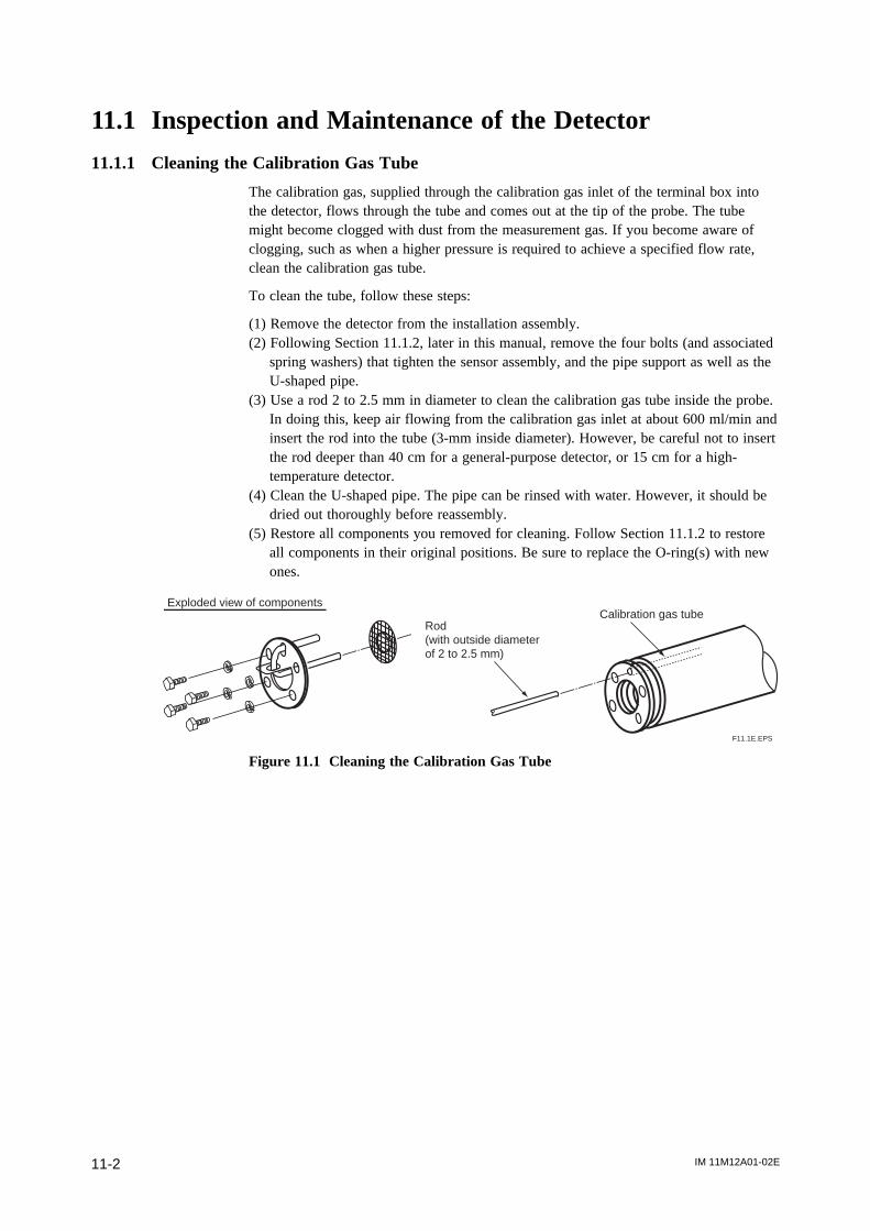
IM 11M12A01-02E11-2
11.1 Inspection and Maintenance of the Detector
11.1.1 Cleaning the Calibration Gas Tube
The calibration gas, supplied through the calibration gas inlet of the terminal box intothe detector, flows through the tube and comes out at the tip of the probe. The tubemight become clogged with dust from the measurement gas. If you become aware ofclogging, such as when a higher pressure is required to achieve a specified flow rate,clean the calibration gas tube.
To clean the tube, follow these steps:
(1) Remove the detector from the installation assembly.(2) Following Section 11.1.2, later in this manual, remove the four bolts (and associated
spring washers) that tighten the sensor assembly, and the pipe support as well as theU-shaped pipe.
(3) Use a rod 2 to 2.5 mm in diameter to clean the calibration gas tube inside the probe.In doing this, keep air flowing from the calibration gas inlet at about 600 ml/min andinsert the rod into the tube (3-mm inside diameter). However, be careful not to insertthe rod deeper than 40 cm for a general-purpose detector, or 15 cm for a high-temperature detector.
(4) Clean the U-shaped pipe. The pipe can be rinsed with water. However, it should bedried out thoroughly before reassembly.
(5) Restore all components you removed for cleaning. Follow Section 11.1.2 to restoreall components in their original positions. Be sure to replace the O-ring(s) with newones.
F11.1E.EPS
Calibration gas tubeExploded view of components
Rod (with outside diameter of 2 to 2.5 mm)
Figure 11.1 Cleaning the Calibration Gas Tube
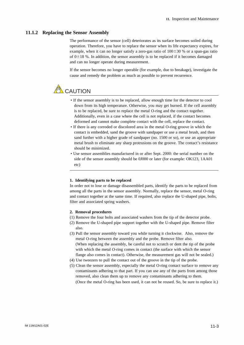
IM 11M12A01-02E 11-3
11. Inspection and Maintenance
11.1.2 Replacing the Sensor Assembly
The performance of the sensor (cell) deteriorates as its surface becomes soiled duringoperation. Therefore, you have to replace the sensor when its life expectancy expires, forexample, when it can no longer satisfy a zero-gas ratio of 100630 % or a span-gas ratioof 0618 %. In addition, the sensor assembly is to be replaced if it becomes damagedand can no longer operate during measurement.
If the sensor becomes no longer operable (for example, due to breakage), investigate thecause and remedy the problem as much as possible to prevent recurrence.
CAUTION
• If the sensor assembly is to be replaced, allow enough time for the detector to cooldown from its high temperature. Otherwise, you may get burned. If the cell assemblyis to be replaced, be sure to replace the metal O-ring and the contact together.Additionally, even in a case where the cell is not replaced, if the contact becomesdeformed and cannot make complete contact with the cell, replace the contact.
• If there is any corroded or discolored area in the metal O-ring groove in which thecontact is embedded, sand the groove with sandpaper or use a metal brush, and thensand further with a higher grade of sandpaper (no. 1500 or so), or use an appropriatemetal brush to eliminate any sharp protrusions on the groove. The contact’s resistanceshould be minimized.
• Use sensor assemblies manufactured in or after Sept. 2000: the serial number on theside of the sensor assembly should be 0J000 or later (for example: OK123, 1AA01
etc)
1. Identifying parts to be replacedIn order not to lose or damage disassembled parts, identify the parts to be replaced fromamong all the parts in the sensor assembly. Normally, replace the sensor, metal O-ringand contact together at the same time. If required, also replace the U-shaped pipe, bolts,filter and associated spring washers.
2. Removal procedures(1) Remove the four bolts and associated washers from the tip of the detector probe.(2) Remove the U-shaped pipe support together with the U-shaped pipe. Remove filter
also.(3) Pull the sensor assembly toward you while turning it clockwise. Also, remove the
metal O-ring between the assembly and the probe. Remove filter also.(When replacing the assembly, be careful not to scratch or dent the tip of the probewith which the metal O-ring comes in contact (the surface with which the sensorflange also comes in contact). Otherwise, the measurement gas will not be sealed.)
(4) Use tweezers to pull the contact out of the groove in the tip of the probe.(5) Clean the sensor assembly, especially the metal O-ring contact surface to remove any
contaminants adhering to that part. If you can use any of the parts from among thoseremoved, also clean them up to remove any contaminants adhering to them.
(Once the metal O-ring has been used, it can not be reused. So, be sure to replace it.)
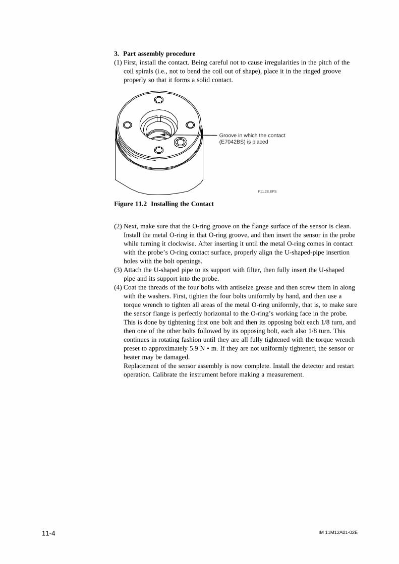
IM 11M12A01-02E11-4
3. Part assembly procedure(1) First, install the contact. Being careful not to cause irregularities in the pitch of the
coil spirals (i.e., not to bend the coil out of shape), place it in the ringed grooveproperly so that it forms a solid contact.
Groove in which the contact(E7042BS) is placed
F11.2E.EPS
Figure 11.2 Installing the Contact
(2) Next, make sure that the O-ring groove on the flange surface of the sensor is clean.Install the metal O-ring in that O-ring groove, and then insert the sensor in the probewhile turning it clockwise. After inserting it until the metal O-ring comes in contactwith the probe’s O-ring contact surface, properly align the U-shaped-pipe insertionholes with the bolt openings.
(3) Attach the U-shaped pipe to its support with filter, then fully insert the U-shapedpipe and its support into the probe.
(4) Coat the threads of the four bolts with antiseize grease and then screw them in alongwith the washers. First, tighten the four bolts uniformly by hand, and then use atorque wrench to tighten all areas of the metal O-ring uniformly, that is, to make surethe sensor flange is perfectly horizontal to the O-ring’s working face in the probe.This is done by tightening first one bolt and then its opposing bolt each 1/8 turn, andthen one of the other bolts followed by its opposing bolt, each also 1/8 turn. Thiscontinues in rotating fashion until they are all fully tightened with the torque wrenchpreset to approximately 5.9 N • m. If they are not uniformly tightened, the sensor orheater may be damaged.Replacement of the sensor assembly is now complete. Install the detector and restartoperation. Calibrate the instrument before making a measurement.
IM 11M12A01-02E 11-5
11. Inspection and Maintenance
F11.3E.EPS
Dust filter (optional) Bolts (four)
Washers (four)
Sensor
U-shaped pipe
Filter
Metal O-ring
ContactProbe
1/8 turn – tighten bolts 1/8 turn (approximately 458) each
U-shaped pipe support
Screw
Figure 11.3 Exploded View of Sensor Assembly
CAUTION
Optional Inconel bolts have a high coefficient of expansion. If excess torque is appliedwhile the bolts are being tightened, abnormal strain or bolt breakage may result. So,tighten the bolts following the instructions given above.
11.1.3 Replacement of the Heater Unit
This section describes the replacement procedure for the heater unit.
The sensor or ceramic heater-furnace core internal structure is subject to fracturing, sodo NOT subject it to strong vibrations or shock. Additionally, the heater unit reacheshigh temperatures and is subjected to high voltages. So, maintenance services should beperformed after the power is off and the heater unit temperature has returned to normalroom temperature.
For details, refer to IM11M12A01-21E " Heater Assembly ".
Note
If the heater strut assembly can not be removed because a screw has fused to its thread,one of our service representatives can fix it.
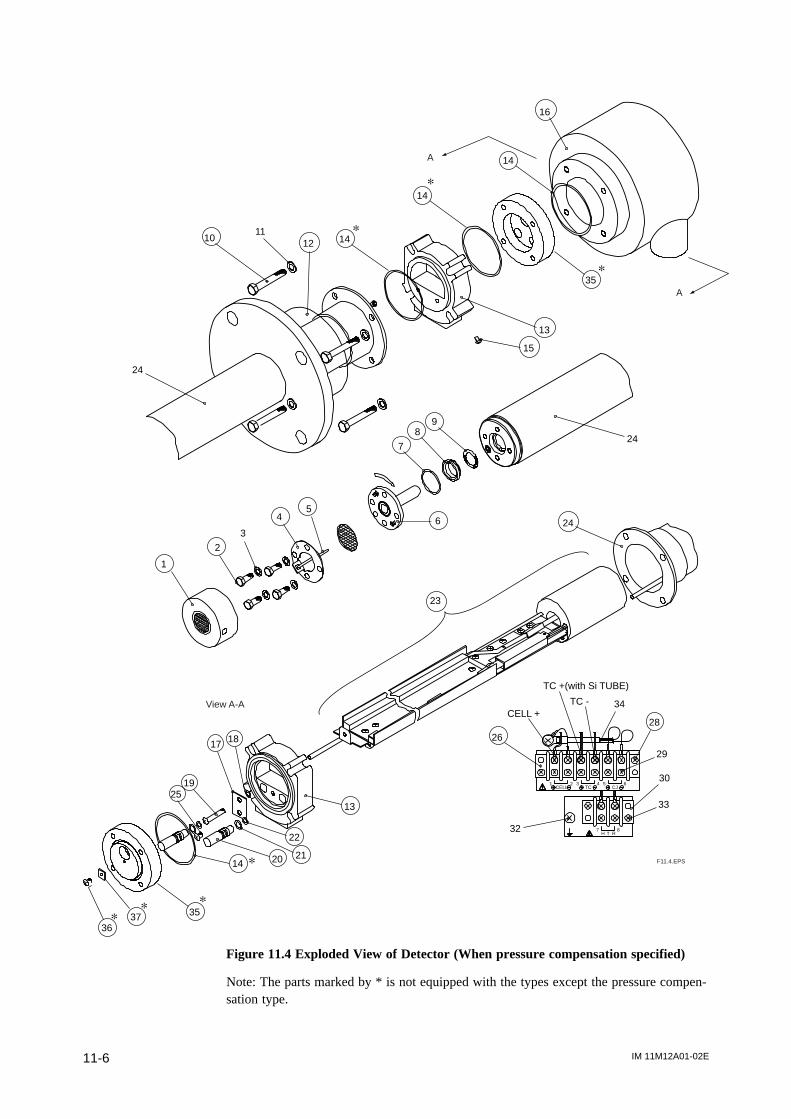
IM 11M12A01-02E11-6
25
1
2
3
45
6
7
89
13
15
14
13
17 18
19
20 21
22
24
24
26
34
28
30
29
33
32
CELL +
TC +(with Si TUBE)
TC -
TCCELL CJ1 2 3 4 5 6
87H T R
F11.4.EPS
1011
12
24
23
View A-A
p
p
p
14
16
14
35
A
A
353736
14
ppp
p
Figure 11.4 Exploded View of Detector (When pressure compensation specified)
Note: The parts marked by * is not equipped with the types except the pressure compen-sation type.

IM 11M12A01-02E 11-7
11. Inspection and Maintenance
Replacement of heater strut assembly (ZR22G : Style S2 and after)Refer to Figure 11.4 as an aid in the following discussion.
Remove the cell assembly (6), following Section 11.1.2, earlier in this manual. Open theterminal box (16) and remove the three terminal connections – CELL +, TC + and TC -.Before disconnect the HTR terminals, remove the terminal block screw (28). Keepingthe other terminal remaining to be connected. Disconnect the two HTR connections.(These terminals have no polarity.)
Remove the two screws (15) that fasten the cover (12) and slide it to the flange side.Remove the four bolts (10) and terminal box (16) with care so that the already discon-nected wire will not get caught in the terminal box.
In case of the pressure compensation type detector, remove the screw (35) and the plate(37) on the adapter (35). Remove the adapter (35), drawing out the wires of the heaterstrut aasy (23) from it.
Loosen Screw (19) until Heater Strut Assembly (23) plate can be removed.
There’s no need to remove O-ring (18) which prevents Screw (19) from coming out.
Pull out connector (13).
Loosen and remove the screw (8) with a special wrench (part no. K9470BX or equiva-lent) and then remove the heater strut assembly (23) from the detector (24).
To reassemble the heater strut assembly, reverse the above procedure:
Insert the heater strut assembly (23) into the detector (24), while inserting the calibrationpipe in the detector (24) into the heater section in the heater strut assembly (23) as wellas in the bracket hole. Coat the screw (8) with grease (NEVER-SEEZ: G7067ZA) andtighten the screw (8) with a special tool (part no. K9470BX or equivalent) with atightening torque of 12N • m ± 10 %.
Next, to install the O-rings (22) on the calibration-gas and reference-gas pipes, disas-semble the connector (13) in the following procedure:
First, remove the screw (25) and then remove the plate (17) and two caps (20). If the O-ring (22) remains in the hole, pull them out from the back. Pass the heater and thermo-couple leadwire through the connector (13). Also, pass the calibration-gas and reference-gas pipes through the opening of the connector (13). If the O-ring (22) fails, replace itwith a new one.
Push the two caps (20) into the associated opening of the connector (13). Insert the plate(17), aligning it with the groove of the cap (20), and tighten it with the screw (25). Ifyou attempt to insert the calibration-gas and reference-gas pipes into the connector (13)without disassembling the connector (13), the O-ring may be damaged. Tighten theTighten Screw (19) in Heater Strut Assembly (23) until connector (13) can’t move.
Reassemble in reverse order to the above disassembly procedure.
The two wires with ceramic insulators from the heater strut assembly are heater wires,and the single-core shielded wire is the cell signal + terminal; for the two-core shieldedcable, the semi-translucent rubber-sheathed wire is the thermocouple + terminal, and theother wire is the 2terminal. (If the wires are marked, match the markings with those onthe terminal board).
When installing the cell assembly (6), replace the metal O-ring (7) with a new one.
IM 11M12A01-02E11-8
11.1.4 Replacement of filter assembly
Set the filter assembly (1) in place using a special pin spanner (with a pin 4.5 mm indiameter: part no. K9471UX or equivalent). If a filter assembly that has already beenreplaced once is used again, apply grease (NEVER-SEEZ: G7067ZA) to the threads ofthe filter assembly.
11.1.5 Replacement of O-ring
The detector uses three different types of O-rings (14), (21), and (22). One O-ring alone(14), or two O-rings (21) and (22) are used. (For a pressure-compensating model, two O-rings are used for individual uses. Two O-rings (21) and (22) are used for reference-gassealing and require periodic replacement.
T11.1.5E.ES
Part No. Deskription
(7) K9470BJ Metak ring
(14) K9470ZS Metal ring with grease
(21) Two pairs of O-rings (22) with grease
K9470ZP
11.1.6 Cleaning the High-temperature Probe Adapter
CAUTION
• Do NOT subject the probe of the High-temperature Probe Adapter (ZO21P-H-A) toshock. This probe uses silicon carbide (SiC) which may become damaged if it issubjected to a strong shock or thermal shock.
The high-temperature detector is structured so that the gas to be measured is directedtoward the detector with the high-temperature probe adapter. Therefore, if the probe orthe sample gas outlet clogs, a precise measurement is no longer possible because of nogas flow. If you use the high-temperature detector, you have to inspect it periodicallyand, if any part of it is significantly clogged with dust, clean it.
Dust found sticking to the probe should be blown off. If any dust still remains after theblowing, clean it with a metal rod, etc., inserted. In addition, if dust is found on theauxiliary ejector or needle valve (choke) at the sample gas outlet, remove these partsfrom the high-temperature probe adapter and then clean them. To remove dust, blow airon them or rinse them with water.
IM 11M12A01-02E 11-9
11. Inspection and Maintenance
11.1.7 Stopping and Re-starting Operation
<Stopping Operation>When operation is stopped, take care of the followings so that the sensor of the detectorcannot become unused.
CAUTION
When operating an instrument such as boiler or industrial furnace is stopped with thezirconia oxygen analyzer operation, moisture can condensate on the sensor portion anddusts may stick to it.
If operation is restarted in this condition, the sensor which is heated up to 7508 C firmlyfix the dusts on itself. Consequently, the dusts can make the sensor performance verylower. If a large amount of water is condensed, the sensor can be broken and never re-useful.
To prevent the above nonconformity, take the following action when stopping operation.
(1) If possible, keep on supplying the power to converter and flowing reference air to the sensor. If impossible to do the above, remove the detector.
(2) If unavoidably impossible to supply the power and removing the detector, keep on following air at 600ml/min into the calibration gas pipe.
<Restarting Operation>When restarting operation, be sure to flow air, for 5-10 minutes, at 600ml/min into thecalibration gas pipe before supplying the power to converter.
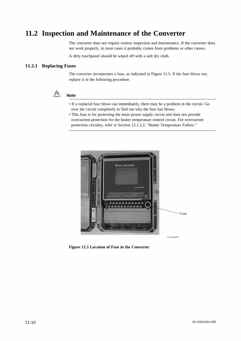
IM 11M12A01-02E11-10
11.2 Inspection and Maintenance of the ConverterThe converter does not require routine inspection and maintenance. If the converter doesnot work properly, in most cases it probably comes from problems or other causes.
A dirty touchpanel should be wiped off with a soft dry cloth.
11.2.1 Replacing Fuses
The converter incorporates a fuse, as indicated in Figure 11.5. If the fuse blows out,replace it in the following procedure.
Note
• If a replaced fuse blows out immediately, there may be a problem in the circuit. Go over the circuit completely to find out why the fuse has blown.• This fuse is for protecting the main power supply circuit and does not provide
overcurrent protection for the heater temperature control circuit. For overcurrentprotection circuitry, refer to Section 12.1.2.2, "Heater Temperature Failure."
F11.5E.EPS
Fuse
Figure 11.5 Location of Fuse in the Converter
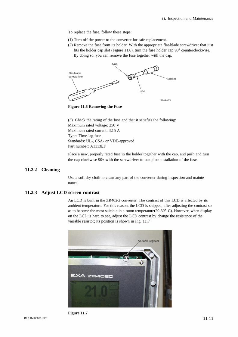
IM 11M12A01-02E 11-11
11. Inspection and Maintenance
To replace the fuse, follow these steps:
(1) Turn off the power to the converter for safe replacement.(2) Remove the fuse from its holder. With the appropriate flat-blade screwdriver that just
fits the holder cap slot (Figure 11.6), turn the fuse holder cap 908 counterclockwise.By doing so, you can remove the fuse together with the cap.
Cap
Flat-blade screwdriver
Fuse
Socket
F11.6E.EPS
Figure 11.6 Removing the Fuse
(3) Check the rating of the fuse and that it satisfies the following:Maximum rated voltage: 250 VMaximum rated current: 3.15 AType: Time-lag fuseStandards: UL-, CSA- or VDE-approvedPart number: A1113EF
Place a new, properly rated fuse in the holder together with the cap, and push and turnthe cap clockwise 90+‹with the screwdriver to complete installation of the fuse.
11.2.2 Cleaning
Use a soft dry cloth to clean any part of the converter during inspection and mainte-nance.
11.2.3 Adjust LCD screen contrast
An LCD is built in the ZR402G converter. The contrast of this LCD is affected by itsambient temperature. For this reason, the LCD is shipped, after adjusting the contrast soas to become the most suitable in a room temperature(20-308 C). However, when displayon the LCD is hard to see, adjust the LCD contrast by change the resistance of thevariable resistor; its position is shown in Fig. 11.7
Variable register
Figure 11.7
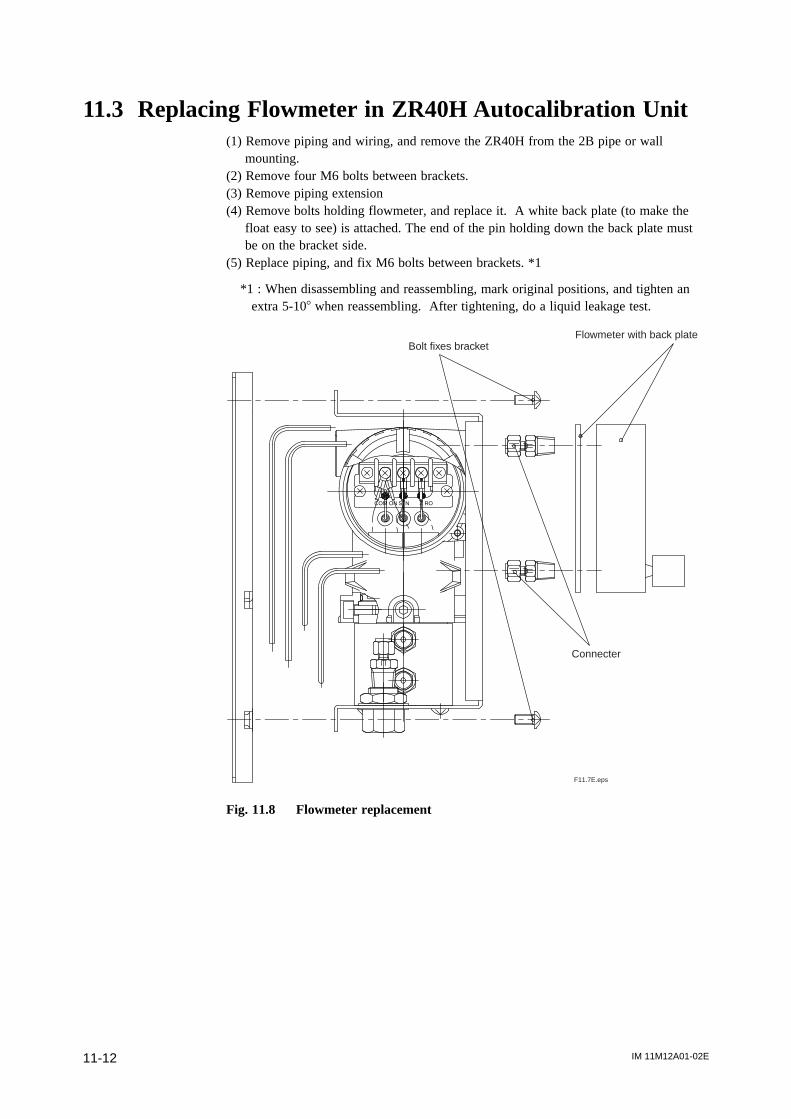
IM 11M12A01-02E11-12
11.3 Replacing Flowmeter in ZR40H Autocalibration Unit(1) Remove piping and wiring, and remove the ZR40H from the 2B pipe or wall
mounting.(2) Remove four M6 bolts between brackets.(3) Remove piping extension(4) Remove bolts holding flowmeter, and replace it. A white back plate (to make the
float easy to see) is attached. The end of the pin holding down the back plate mustbe on the bracket side.
(5) Replace piping, and fix M6 bolts between brackets. *1
*1 : When disassembling and reassembling, mark original positions, and tighten anextra 5-108 when reassembling. After tightening, do a liquid leakage test.
COM ON S N Z RO
F11.7E.eps
Bolt fixes bracketFlowmeter with back plate
Connecter
Fig. 11.8 Flowmeter replacement
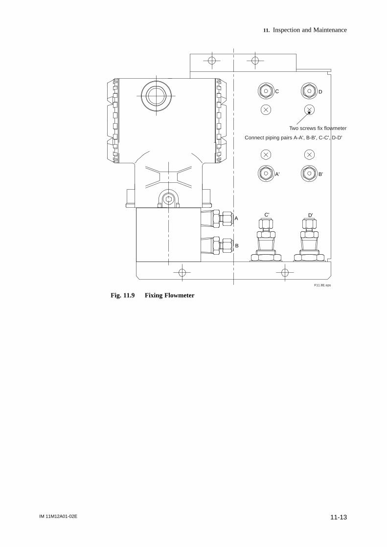
IM 11M12A01-02E 11-13
11. Inspection and Maintenance
F11.8E.eps
A
A'
B
B'
C
C'
D
D'
Two screws fix flowmeter
Connect piping pairs A-A', B-B', C-C', D-D'
Fig. 11.9 Fixing Flowmeter

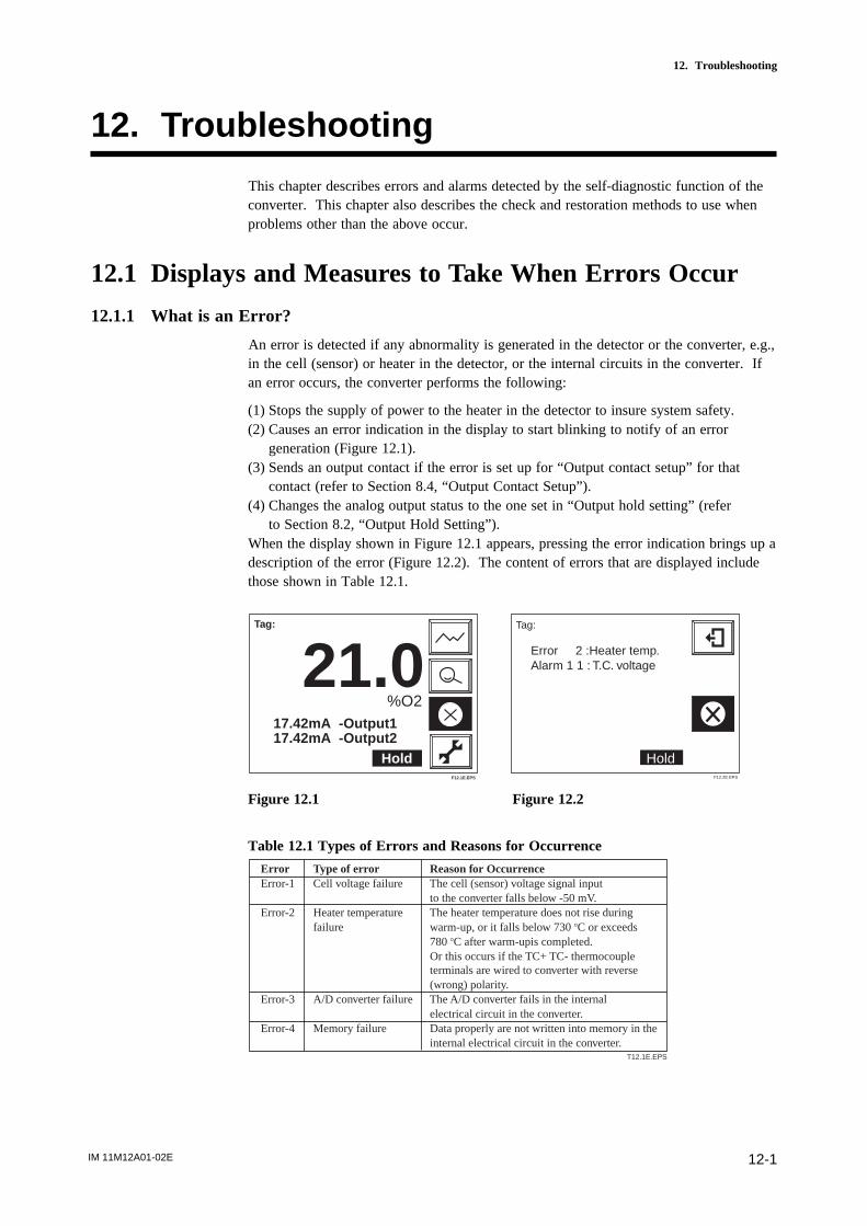
IM 11M12A01-02E 12-1
12. Troubleshooting
12. Troubleshooting
This chapter describes errors and alarms detected by the self-diagnostic function of theconverter. This chapter also describes the check and restoration methods to use whenproblems other than the above occur.
12.1 Displays and Measures to Take When Errors Occur
12.1.1 What is an Error?
An error is detected if any abnormality is generated in the detector or the converter, e.g.,in the cell (sensor) or heater in the detector, or the internal circuits in the converter. Ifan error occurs, the converter performs the following:
(1) Stops the supply of power to the heater in the detector to insure system safety.(2) Causes an error indication in the display to start blinking to notify of an error
generation (Figure 12.1).(3) Sends an output contact if the error is set up for “Output contact setup” for that
contact (refer to Section 8.4, “Output Contact Setup”).(4) Changes the analog output status to the one set in “Output hold setting” (refer
to Section 8.2, “Output Hold Setting”).When the display shown in Figure 12.1 appears, pressing the error indication brings up adescription of the error (Figure 12.2). The content of errors that are displayed includethose shown in Table 12.1.
Tag:
21.0%O2
17.42mA -Output117.42mA -Output2
HoldF12.1E.EPS
Tag:
Error 2 :Heater temp.Alarm 1 1 : T.C. voltage
HoldF12.2E.EPS
Figure 12.1 Figure 12.2
Table 12.1 Types of Errors and Reasons for Occurrence
Error Type of error Reason for OccurrenceError-1 Cell voltage failure The cell (sensor) voltage signal input
to the converter falls below -50 mV.Error-2 Heater temperature The heater temperature does not rise during
failure warm-up, or it falls below 730 8C or exceeds 780 8C after warm-upis completed.
Or this occurs if the TC+ TC- thermocouple terminals are wired to converter with reverse (wrong) polarity. Error-3 A/D converter failure The A/D converter fails in the internal
electrical circuit in the converter.Error-4 Memory failure Data properly are not written into memory in the
internal electrical circuit in the converter.T12.1E.EPS
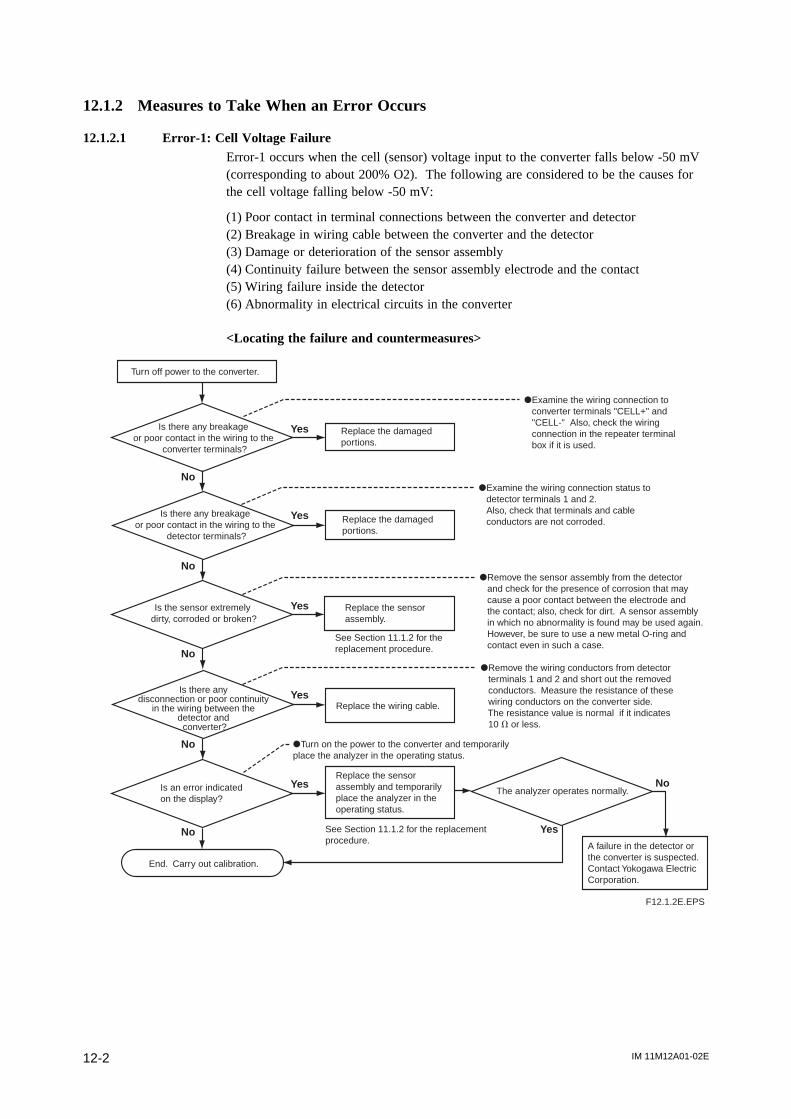
IM 11M12A01-02E12-2
12.1.2 Measures to Take When an Error Occurs
12.1.2.1 Error-1: Cell Voltage FailureError-1 occurs when the cell (sensor) voltage input to the converter falls below -50 mV(corresponding to about 200% O2). The following are considered to be the causes forthe cell voltage falling below -50 mV:
(1) Poor contact in terminal connections between the converter and detector(2) Breakage in wiring cable between the converter and the detector(3) Damage or deterioration of the sensor assembly(4) Continuity failure between the sensor assembly electrode and the contact(5) Wiring failure inside the detector(6) Abnormality in electrical circuits in the converter
<Locating the failure and countermeasures>
No
Yes
Yes
Yes
Yes
Yes
Yes
No
No
No
No
No
Turn off power to the converter.
Is there any breakage or poor contact in the wiring to the
converter terminals?
Is there any breakage or poor contact in the wiring to the
detector terminals?
Is the sensor extremely dirty, corroded or broken?
Is there any disconnection or poor continuity
in the wiring between the detector and
converter?
Is an error indicated on the display?
End. Carry out calibration.
Replace the damaged portions.
dExamine the wiring connection to converter terminals "CELL+" and "CELL-" Also, check the wiring connection in the repeater terminal box if it is used.
dExamine the wiring connection status to detector terminals 1 and 2. Also, check that terminals and cable conductors are not corroded.Replace the damaged
portions.
dRemove the sensor assembly from the detector and check for the presence of corrosion that may cause a poor contact between the electrode and the contact; also, check for dirt. A sensor assembly in which no abnormality is found may be used again. However, be sure to use a new metal O-ring and contact even in such a case.
Replace the sensor assembly.
See Section 11.1.2 for the replacement procedure.
dRemove the wiring conductors from detector terminals 1 and 2 and short out the removed conductors. Measure the resistance of these wiring conductors on the converter side. The resistance value is normal if it indicates 10 V or less.
Replace the wiring cable.
dTurn on the power to the converter and temporarily place the analyzer in the operating status.
Replace the sensor assembly and temporarily place the analyzer in the operating status.
See Section 11.1.2 for the replacement procedure.
The analyzer operates normally.
A failure in the detector or the converter is suspected. Contact Yokogawa Electric Corporation.
F12.1.2E.EPS
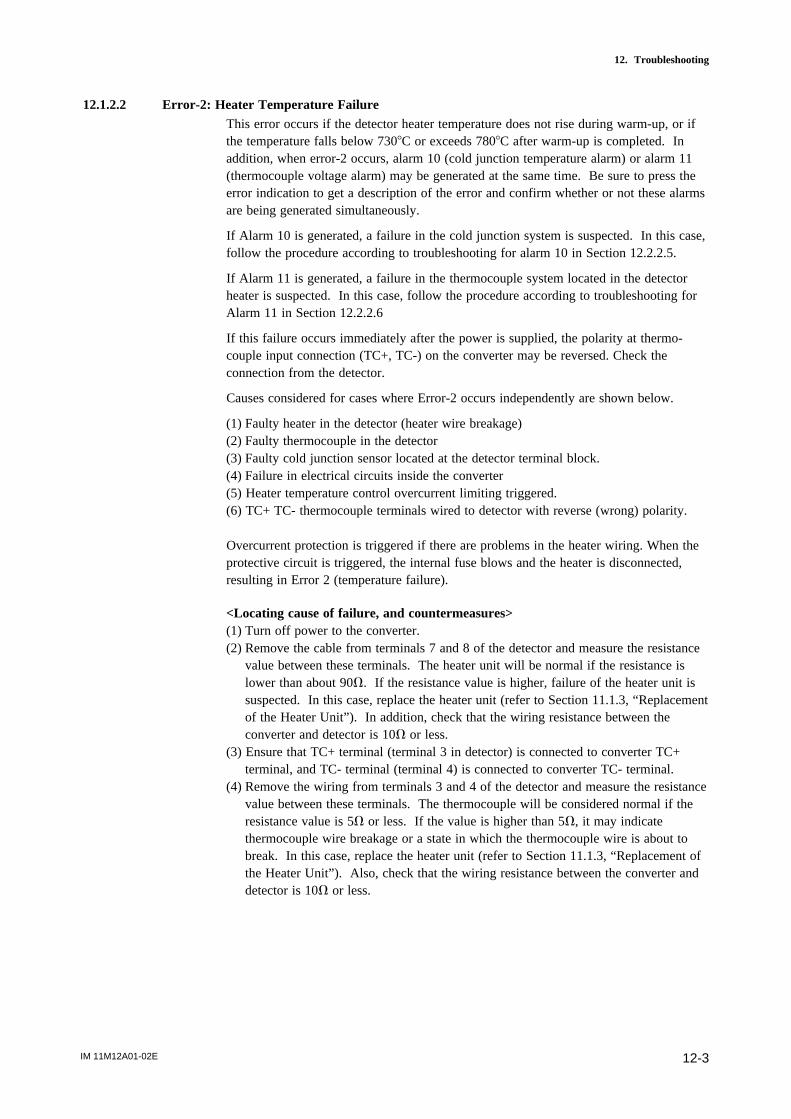
IM 11M12A01-02E 12-3
12. Troubleshooting
12.1.2.2 Error-2: Heater Temperature FailureThis error occurs if the detector heater temperature does not rise during warm-up, or ifthe temperature falls below 7308C or exceeds 7808C after warm-up is completed. Inaddition, when error-2 occurs, alarm 10 (cold junction temperature alarm) or alarm 11(thermocouple voltage alarm) may be generated at the same time. Be sure to press theerror indication to get a description of the error and confirm whether or not these alarmsare being generated simultaneously.
If Alarm 10 is generated, a failure in the cold junction system is suspected. In this case,follow the procedure according to troubleshooting for alarm 10 in Section 12.2.2.5.
If Alarm 11 is generated, a failure in the thermocouple system located in the detectorheater is suspected. In this case, follow the procedure according to troubleshooting forAlarm 11 in Section 12.2.2.6
If this failure occurs immediately after the power is supplied, the polarity at thermo-couple input connection (TC+, TC-) on the converter may be reversed. Check theconnection from the detector.
Causes considered for cases where Error-2 occurs independently are shown below.
(1) Faulty heater in the detector (heater wire breakage)(2) Faulty thermocouple in the detector(3) Faulty cold junction sensor located at the detector terminal block.(4) Failure in electrical circuits inside the converter(5) Heater temperature control overcurrent limiting triggered.(6) TC+ TC- thermocouple terminals wired to detector with reverse (wrong) polarity.
Overcurrent protection is triggered if there are problems in the heater wiring. When theprotective circuit is triggered, the internal fuse blows and the heater is disconnected,resulting in Error 2 (temperature failure).
<Locating cause of failure, and countermeasures>(1) Turn off power to the converter.(2) Remove the cable from terminals 7 and 8 of the detector and measure the resistance
value between these terminals. The heater unit will be normal if the resistance islower than about 90V. If the resistance value is higher, failure of the heater unit issuspected. In this case, replace the heater unit (refer to Section 11.1.3, “Replacementof the Heater Unit”). In addition, check that the wiring resistance between theconverter and detector is 10V or less.
(3) Ensure that TC+ terminal (terminal 3 in detector) is connected to converter TC+terminal, and TC- terminal (terminal 4) is connected to converter TC- terminal.
(4) Remove the wiring from terminals 3 and 4 of the detector and measure the resistancevalue between these terminals. The thermocouple will be considered normal if theresistance value is 5V or less. If the value is higher than 5V, it may indicatethermocouple wire breakage or a state in which the thermocouple wire is about tobreak. In this case, replace the heater unit (refer to Section 11.1.3, “Replacement ofthe Heater Unit”). Also, check that the wiring resistance between the converter anddetector is 10V or less.
IM 11M12A01-02E12-4
(5) Even if items (2) to (4) are normal, the heater overcurrent protection fuse may haveblown. Check for wiring problems such as the following:1) Heater terminals shorted.2) Heater terminal(s) shorted to ground.3) Heater terminals shorted to power supply.
If the internal fuse blows, this cannot be replaced by the user. Contact your Yokogawaservice representative.
CAUTION
• Measure the thermocouple resistance value after the difference between the detectortip temperature and the ambient temperature decreases to 508C or less. If the thermo-couple voltage is large, accurate measurement cannot be achieved.
12.1.2.3 Error-3: A/D Converter Failure/Error-4: Writing-to-memory Failure• A/D Converter FailureIt is suspected that a failure has occurred in the A/D converter mounted in the electricalcircuits inside the converter.
• Writing-to memory FailureIt is suspected that a failure has occurred in an operation writing to the memory(EEPROM) mounted in the electrical circuits inside the converter.
<Locating the failure, and countermeasures>Turn off the power to the converter once and then restart the converter. If the converteroperates normally after restarting, an error might have occurred due to a temporary dropin the voltage (falling below 85 V, the least amount of voltage required to operate theconverter) or a malfunction of the electrical circuits affected by noise. Check whether ornot there is a failure in the power supply system or whether the converter and detectorare securely grounded.
If the error occurs again after restarting, a failure in the electrical circuits is suspected.Consult the service personnel at Yokogawa Electric Corporation.
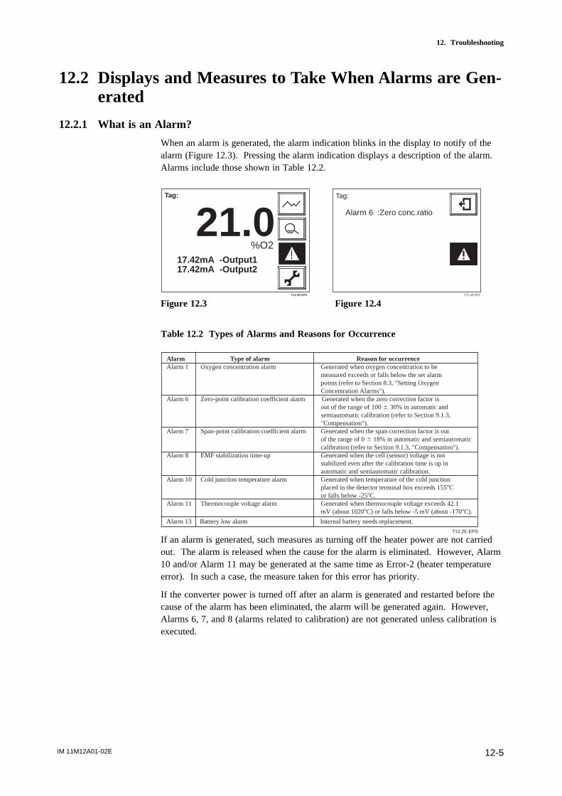
IM 11M12A01-02E 12-5
12. Troubleshooting
12.2 Displays and Measures to Take When Alarms are Gen-erated
12.2.1 What is an Alarm?
When an alarm is generated, the alarm indication blinks in the display to notify of thealarm (Figure 12.3). Pressing the alarm indication displays a description of the alarm.Alarms include those shown in Table 12.2.
Tag:
21.0%O2
17.42mA -Output117.42mA -Output2
F12.3E.EPS
Tag:
Alarm 6 :Zero conc.ratio
F12.4E.EPS
Figure 12.3 Figure 12.4
Table 12.2 Types of Alarms and Reasons for Occurrence
T12.2E.EPS
Alarm Type of alarm Reason for occurrenceAlarm 1 Oxygen concentration alarm Generated when oxygen concentration to be
measured exceeds or falls below the set alarm points (refer to Section 8.3, "Setting Oxygen Concentration Alarms").
Alarm 6 Zero-point calibration coefficient alarm Generated when the zero correction factor is out of the range of 100 6 30% in automatic and semiautomatic calibration (refer to Section 9.1.3, "Compensation").
Alarm 7 Span-point calibration coefficient alarm Generated when the span correction factor is out of the range of 0 6 18% in automatic and semiautomatic calibration (refer to Section 9.1.3, "Compensation").
Alarm 8 EMF stabilization time-up Generated when the cell (sensor) voltage is not stabilized even after the calibration time is up in automatic and semiautomatic calibration.
Alarm 10 Cold junction temperature alarm Generated when temperature of the cold junction placed in the detector terminal box exceeds 1558C or falls below -258C.
Alarm 11 Thermocouple voltage alarm Generated when thermocouple voltage exceeds 42.1 mV (about 10208C) or falls below -5 mV (about -1708C).
Alarm 13 Battery low alarm Internal battery needs replacement.
If an alarm is generated, such measures as turning off the heater power are not carriedout. The alarm is released when the cause for the alarm is eliminated. However, Alarm10 and/or Alarm 11 may be generated at the same time as Error-2 (heater temperatureerror). In such a case, the measure taken for this error has priority.
If the converter power is turned off after an alarm is generated and restarted before thecause of the alarm has been eliminated, the alarm will be generated again. However,Alarms 6, 7, and 8 (alarms related to calibration) are not generated unless calibration isexecuted.

IM 11M12A01-02E12-6
12.2.2 Measures Taken When Alarms are Generated
12.2.2.1 Alarm 1: Oxygen Concentration AlarmThis alarm is generated when a measured value exceeds an alarm set point or falls
below it. For details on the oxygen concentration alarm, see Section 8.3, “SettingOxygen Concentration Alarms,” in the chapter on operation.
12.2.2.2 Alarm 6: Zero-point Calibration Coefficient AlarmIn automatic or semiautomatic calibration, this alarm is generated when the zerocorrection factor is out of the range of 100 6 30% (refer to Section 9.1.3, “Compensa-tion”). The following can be considered the causes for this:
(1) The zero-gas oxygen concentration does not agree with the value of the zero-gasconcentration set “Calibration Setup.” Otherwise, the span gas is used as the zerogas.
(2) The zero-gas flow is out of the specified flow (600 660 mL/min).(3) The sensor assembly is damaged and so cell voltage is not normal.
<Locating cause of failure, and countermeasures>(1) Confirm the following and carry out calibration again: If the items are not within
their proper states, correct them.a. If the indication for “Zero gas conc.” is selected in “Calibration setup,” the set
point should agree with the concentration of zero gas actually used.b. The calibration gas tubing should be constructed so that the zero gas does not
leak.(2) If no alarm is generated as a result of carrying out re-calibration, it is suspected that
improper calibration conditions were the cause of the alarm in the preceding calibra-tion. In this case, no specific restoration is necessary.
(3) If an alarm is generated again as a result of carrying out re-calibration, deteriorationof or damage to the sensor assembly is suspected as the cause of the alarm. Replace-ment of the cell with a new one is necessary. However, before replacement, carryout the following:Check the cell voltages when passing the zero gas and span gas.a. Display the detailed data display by pressing the detail display key in the basic
panel display.b. When the . key is pressed once, the cell voltage should be indicated on the
top line (Figure 12.5).c. Check whether or not the value of the displayed cell voltage is very different
from the theoretical value at each oxygen concentration. Confirm the theoretical values of the cell voltage in Table 12.3. Although it cannot be generallyspecified as to what extent the difference from the theoretical value is allowed,consider it to be approximately 610 mV.
Table 12.3 Oxygen Concentration and Cell Voltage
T12.3E.EPS
Oxygen concentration Cell voltage (%O2) (mV)
1 % 67.1
21% 0

IM 11M12A01-02E 12-7
12. Troubleshooting
(4) Confirm whether deterioration of or damage to the sensor assembly that caused thealarm has occurred abruptly during the current calibration in the following procedure:a. Call up the detailed data display.b. Display “Calibration time history” by pressing the . key (Figure 12.6). Since
the ten previous span-correction factor and zero-correction factor valuescan be checked in this display, changes in deterioration of thesensor can be seen.
Cell voltage: 0 . 6 mVThermo voltage: 4 2 . 1 mVC.J.resistance: 1 1 8 1 . 4 VCell resistance: - 4 VSoft.rev.: 0 . 2 4
Tag:
F12.5E.EPS
Hold
Calibration data: 1: 2 0 0 0 / 07 / 07 1 4 : 57 Span gas ratio: - 2 . 9 % Zero gas ratio: 7 0 . 3 % 2: 2 0 0 0 / 07 / 07 1 4 : 5 4 Span gas ratio: - 2 . 9 % Zero gas ratio: 8 9 . 7 %
Tag:
Hold
Figure 12.5 Detailed Data Display Figure 12.6 Calibration History
(5) If deterioration of the sensor assembly has occurred abruptly, it may show that thecheck valve, which prevents moisture in the furnace from getting into the calibrationgas tubing, has failed. If the gas in the furnace gets into the calibration gas tubing, itcondenses and remains in the gas tubing as condensate. The sensor assembly isconsidered to be broken for the reason that the condensate is blown into the sensorassembly by the calibration gas during calibration and so the cell cools quickly.
(6) If the sensor assembly has been gradually deteriorating, check the sensor assemblystatus in the following procedure:a. Display “Cell resistance” by pressing the . key. A new cell will show a cell
resistance value of 200V or less. On the other hand, a cell (sensor) that isapproaching the end of its service life will show a resistance value of 3 to 10kV.
b. Display “Cell robustness” by pressing the . key. A good cell (sensor) willshow “Life > 1 year” (Figure 12.7).
Span gas ratio: - 2 . 9 %Zero gas ratio: 7 0 . 3 %Response time: 0 sCell robustness: life< 1 monthCell temperature: 1 0 6 7 8CC.J.temperature: 4 7 8C
Tag:
HoldF12.7E.EPS
Figure 12.7
12.2.2.3 Alarm 7: Span-point Calibration Coefficient AlarmIn automatic or semiautomatic calibration, this alarm is generated when the spancorrection factor is out of the range of 0 6 18% (refer to Section 9.1.3, “Compensa-tion”). The following are suspected as the cause:
(1) The oxygen concentration of the span gas does not agree with the value of the spangas set “Calibration setup.”
(2) The flow of the span gas is out of the specified flow value (600 660 mL/min).(3) The sensor assembly is damaged and the cell voltage is abnormal.
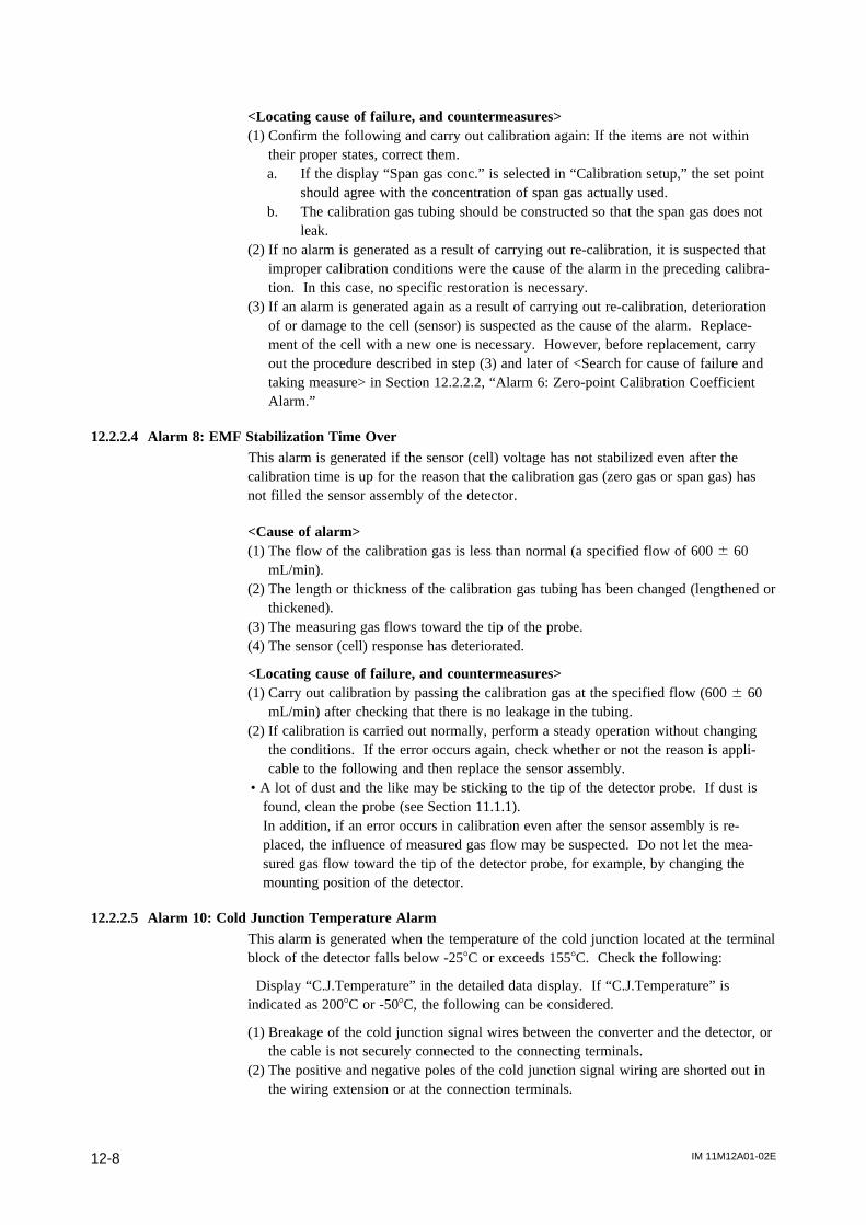
IM 11M12A01-02E12-8
<Locating cause of failure, and countermeasures>(1) Confirm the following and carry out calibration again: If the items are not within
their proper states, correct them.a. If the display “Span gas conc.” is selected in “Calibration setup,” the set point
should agree with the concentration of span gas actually used.b. The calibration gas tubing should be constructed so that the span gas does not
leak.(2) If no alarm is generated as a result of carrying out re-calibration, it is suspected that
improper calibration conditions were the cause of the alarm in the preceding calibra-tion. In this case, no specific restoration is necessary.
(3) If an alarm is generated again as a result of carrying out re-calibration, deteriorationof or damage to the cell (sensor) is suspected as the cause of the alarm. Replace-ment of the cell with a new one is necessary. However, before replacement, carryout the procedure described in step (3) and later of <Search for cause of failure andtaking measure> in Section 12.2.2.2, “Alarm 6: Zero-point Calibration CoefficientAlarm.”
12.2.2.4 Alarm 8: EMF Stabilization Time OverThis alarm is generated if the sensor (cell) voltage has not stabilized even after thecalibration time is up for the reason that the calibration gas (zero gas or span gas) hasnot filled the sensor assembly of the detector.
<Cause of alarm>(1) The flow of the calibration gas is less than normal (a specified flow of 600 6 60
mL/min).(2) The length or thickness of the calibration gas tubing has been changed (lengthened or
thickened).(3) The measuring gas flows toward the tip of the probe.(4) The sensor (cell) response has deteriorated.
<Locating cause of failure, and countermeasures>(1) Carry out calibration by passing the calibration gas at the specified flow (600 6 60
mL/min) after checking that there is no leakage in the tubing.(2) If calibration is carried out normally, perform a steady operation without changing
the conditions. If the error occurs again, check whether or not the reason is appli-cable to the following and then replace the sensor assembly.
• A lot of dust and the like may be sticking to the tip of the detector probe. If dust isfound, clean the probe (see Section 11.1.1).In addition, if an error occurs in calibration even after the sensor assembly is re-placed, the influence of measured gas flow may be suspected. Do not let the mea-sured gas flow toward the tip of the detector probe, for example, by changing themounting position of the detector.
12.2.2.5 Alarm 10: Cold Junction Temperature AlarmThis alarm is generated when the temperature of the cold junction located at the terminalblock of the detector falls below -258C or exceeds 1558C. Check the following:
Display “C.J.Temperature” in the detailed data display. If “C.J.Temperature” isindicated as 2008C or -508C, the following can be considered.
(1) Breakage of the cold junction signal wires between the converter and the detector, orthe cable is not securely connected to the connecting terminals.
(2) The positive and negative poles of the cold junction signal wiring are shorted out inthe wiring extension or at the connection terminals.
IM 11M12A01-02E 12-9
12. Troubleshooting
(3) A failure of the cold junction temperature sensor located at the detector terminalblock occurred.
(4) A failure of the electrical circuits inside the converter occurred.If “C.J.Temperature” exceeds 1508C or falls below -208C, the following can beconsidered.
(1) The temperature of the detector terminal block is out of the operating temperaturerange (-208C to 1508C).
(2) A failure of the cold junction temperature sensor located at the detector terminalblock occurred.
(3) A failure of the electrical circuits inside the converter occurred.
<Locating cause of failure and countermeasures>Before proceeding to the following troubleshooting procedure, examine whether or notthe temperature of the detector terminal block is out of the operating temperature range.The operating temperature range varies with the type of detector. If the detectorterminal block is out of its operating temperature range, take the measure to lower thetemperature, such as situating it so that it is not subjected to radiant heat.
The case where the Model ZR22 Detector is used:(1) Stop the power to the converter.(2) Remove the wiring from terminals 5 and 6 of the detector and measure the resistance
between these terminals. If the resistance value is out of the range of 1 to 1.6 kV,the cold junction temperature sensor is considered to be faulty. Replace that tem-perature sensor with a new one.
(3) If the resistance value is within the above range, the cold junction temperature sensorseems to be normal. Check whether or not the cable is broken or shorted out, andwhether the cable is securely connected to the terminals. Also, check that theresistance of the wiring between the converter and detector is 10V or less.
(4) If there is no failure in the wiring, the electrical circuits inside the converter maypossibly fail. Contact the service personnel at Yokogawa Electric Corporation.
The case where the Model ZO21D Detector is used:(1) Without stopping the power to the converter, remove the wiring from terminals 5 and
6 of the detector and measure the voltage between these terminals. If the voltagebetween the terminals is out of the range of 0.4 to 0.7 V, the cold junction tempera-ture sensor seems to be faulty. Replace the cold junction temperature sensor.
(2) If the voltage between the terminals is within the above range, the cold junctiontemperature sensor seems to be normal. Check whether or not the cable is broken orshorted out, and whether the cable is securely connected to the terminals. Also,check that the resistance of the wiring between the converter and detector is 10V orless.
(3) If there is no failure in the wiring, the electrical circuits inside the converter maypossibly fail. Contact the service personnel at Yokogawa Electric Corporation.
CAUTION
• The operating temperature range of the Model ZO21D Detector is -108C to 808C(except for the high-temperature detector ZO21D-H). Since a cold junction tempera-ture alarm for this analyzer is not generated until the temperature exceeds 1558C, ifthe Model ZO21D Detector is used, be careful in controlling the ambient temperatureof the terminal block.

IM 11M12A01-02E12-10
12.2.2.6 Alarm 11: Thermocouple Voltage AlarmThis alarm is generated when the emf (voltage) of the thermocouple falls below -5 mV(about -1708C) or exceeds 42.1 mV (about 10208C). Whenever Alarm 11 is generated,Error-2 (heater temperature failure) occurs.
(1) Breakage of the heater thermocouple signal wire between the converter and thedetector occurred, or the cable is not securely connected to the connecting terminals.
(2) The positive and negative poles of the heater thermocouple signal wiring are shortedout in the wiring extension or at the connection terminals.
(3) A failure of the thermocouple at the detector heater assembly occurred.(4) A failure of the electrical circuits inside the converter occurred.
<Locating cause of failure, and countermeasures>(1) Stop the power to the converter.(2) Remove the wiring from terminals 3 and 4 of the detector and measure the resistance
between these terminals. If the resistance value is 5V or less, the thermocoupleseems to be normal. If it is higher than 5V, it may indicate the possibility that thethermocouple has broken or is about to break. In this case, replace the heater unit(refer to Section 11.1.3, “Replacement of the Heater Unit”).
CAUTION
• Measure the thermocouple resistance value after the difference between the detectortip temperature and ambient temperature falls to 508C or less. If the thermocouplevoltage is large, accurate measurement cannot be achieved.
(3) If the thermocouple is normal, check whether or not the wiring cable is broken orshorted out, and also whether the wiring cable is securely connected to the terminals.Also check that the wiring resistance between the converter and the detector is 10V
or less.(4) If there is no failure in the wiring, the electrical circuits inside the converter may
possibly fail. Contact the service personnel at Yokogawa Electric Corporation.
12.2.2.7 Alarm 13: Battery Low AlarmAn internal battery is used as backup for the clock. After this alarm occurs, removingpower from the instrument may cause the clock to stop but should not affect storedparameters. The internal clock is used for blowback scheduling; if you use this then aftera battery alarm occurs (until the battery is replaced) be sure to check / correct the dateand time every time you turn on the power.
<Corrective action>When the battery low alarm occurs, remember that the battery cannot be replaced by theuser. Contact your Yokogawa service representative.
Note
Battery life varies with environmental conditions.* If power is applied to the instrument continuously, then the battery should not run
down, and life is typically about ten years. However the battery will be used duringthe time interval between shipment from the factory and installation.
* If power is not applied to the instrument, at normal room temperatures of 20 to 258Cthen battery life is typically 5 years, and outside this range but within the range -30 to+708C then battery life is typically 1 year.
IM 11M12A01-02E 12-11
12. Troubleshooting
12.3 Countermeasures When Measured Value Shows ErrorThe causes that the measured value shows an abnormal value is not always due toinstrument failures. There are rather many cases where the causes are those that measur-ing gas itself is in abnormal state or external causes exist, which disturb the instrumentoperation. In this section, causes of and measures against the cases where measuredvalues show the following phenomena will be described.
(1) The measured value is higher than the true value.(2) The measured value is lower than the true value.(3) The measured value sometimes shows abnormal values.
12.3.1 Measured Value Higher Than True Value
<Causes and Countermeasures>(1) The measuring gas pressure becomes higher.
The measured oxygen concentration value X (vol% O2) is expressed as shown below,
when the measuring gas pressure is higher than that in calibration by Dp (kPa).X=Y [ 1+ (Dp/101.30) ]where Y: Measured oxygen concentration value at the same pressure as incalibration (vol% O
2).
Where an increment of the measured value by pressure change cannot be neglected,measures must be taken.
Investigate the following points to perform improvement available in each process.dIs improvement in facility's aspect available so that pressure change does not occur?dIs performing calibration available under the average measuring gas pressure
(internal pressure of a furnace)?(2) Moisture content in a reference gas changes (increases) greatly.
If air at the detector installation site is used for the reference gas, large change ofmoisture in the air may cause an error in measured oxygen concentration value(vol% O
2).
When this error is not ignored, use a gas in which moisture content is constant suchas instrument air in almost dry condition as a reference gas.
In addition, change of moisture content in exhaust gas after combustion is alsoconsidered as a cause of error. However, normally this error is negligible.
(3) Calibration gas (span gas) is mixing into the detector due to leakage.If the span gas is mixing into the detector due to leakage as a result of failure of the
valve provided in the calibration gas tubing system, the measured value shows avalue a little higher than normal.
Check valves (needle valves, check valves, solenoid valves for automatic calibration,etc.) in the calibration gas tubing system for leakage. For manual valves, checkthem after confirming that they are in fully closed states. In addition, check thetubing joints for leakage.
(4) The reference gas is mixing into the measuring gas and vice versa.Since the difference between oxygen partial pressures on the sensor anode and
cathode sides becomes smaller, the measured value shows a higher value.An error which does not appear as the Error-1 may occur in the sensor. Measured gas
and/or the reference gas may be leaking. Visually inspect the sensor. If any crack isfound, replace the sensor assembly with a new one.
(Note) Data such as cell robustness displayed in the detailed data display should alsobe used for deciding sensor quality as references.

IM 11M12A01-02E12-12
12.3.2 Measured Value Lower Than True Value
<Causes and Countermeasures>(1) The measuring gas pressure becomes lower.
Where an increment of the measured value due to pressure change cannot be ne-glected, take measures referring to subsection 12.3.1 (1).
(2) Moisture content in a reference gas changes (decreases) greatly.If air at the detector installation site is used for the reference gas, large change of
moisture content in the air may cause an error in measured oxygen concentrationvalue (vol% O
2).
When this error is not ignored, use a gas in which moisture content is constant suchas instrument air in almost dry condition as a reference gas.
In addition, change of moisture content in exhaust gas after combustion is alsoconsidered as a cause of error. However, normally this error is negligible.
(3) Calibration gas (zero gas) is mixed into the detector due to leakage.If the zero gas is mixed into the detector due to leakage as a result of failure of the
valve provided in the calibration gas tubing system, the measured value shows avalue a little lower than normal.
Check valves (needle valves, check valves, solenoid valves for automatic calibration,etc.) in the calibration gas tubing system for leakage. For manual valves, checkthem after confirming that they are in fully closed states.
(4) Conbustible components exist in the measured gas. If combustible components existin the measured gas, they burn in the sensor and thus oxygen concentartion decreses.Check that there are no combustible components.
(5) Temperature of the detector cell reaches 750 8C or more.
12.3.3 Measurements Sometimes Show Abnormal Values
<Cause and Countermeasures>(1) Noise may be mixing in with the converter from the detector output wiring.
Check whether the converter and detector are securely grounded.Check whether or not the signal wiring is laid along other power cords.
(2) The converter may be affected by noise from the power supply.Check whether or not the converter power is supplied from the same outlet, switch,or breaker as other power machines and equipment.
(3) Poor wiring contactIf there is poor contact in the wiring, the sensor voltage or thermocouple emf(voltage) may vary due to vibration or other factors.Check whether or not there are loose points in the wiring connections or loosecrimping (caulking) at the crimp-on terminal lugs.
(4) Combustible components in the measured gas may be getting into the sensor.If the combustible components show signs of dust, the abnormality may be im-proved by mounting a dust-removing filter K9471UA.
(5) There may be a crack in the sensor or leakage at the sensor-mounting portion.If the indication of concentration varies in synchronization with the pressure changein the furnace, check whether or not there is a crack in the sensor or whether thesensor flange is sticking tightly to the probe-attaching face with the metal O-ringsqueezed.
(6) There may be leakage in the calibration gas tubingIn the case of a negative furnace inner pressure, if the indication of concentrationvaries with the pressure change in the furnace, check whether or not there is leakagein the calibration gas tubing.
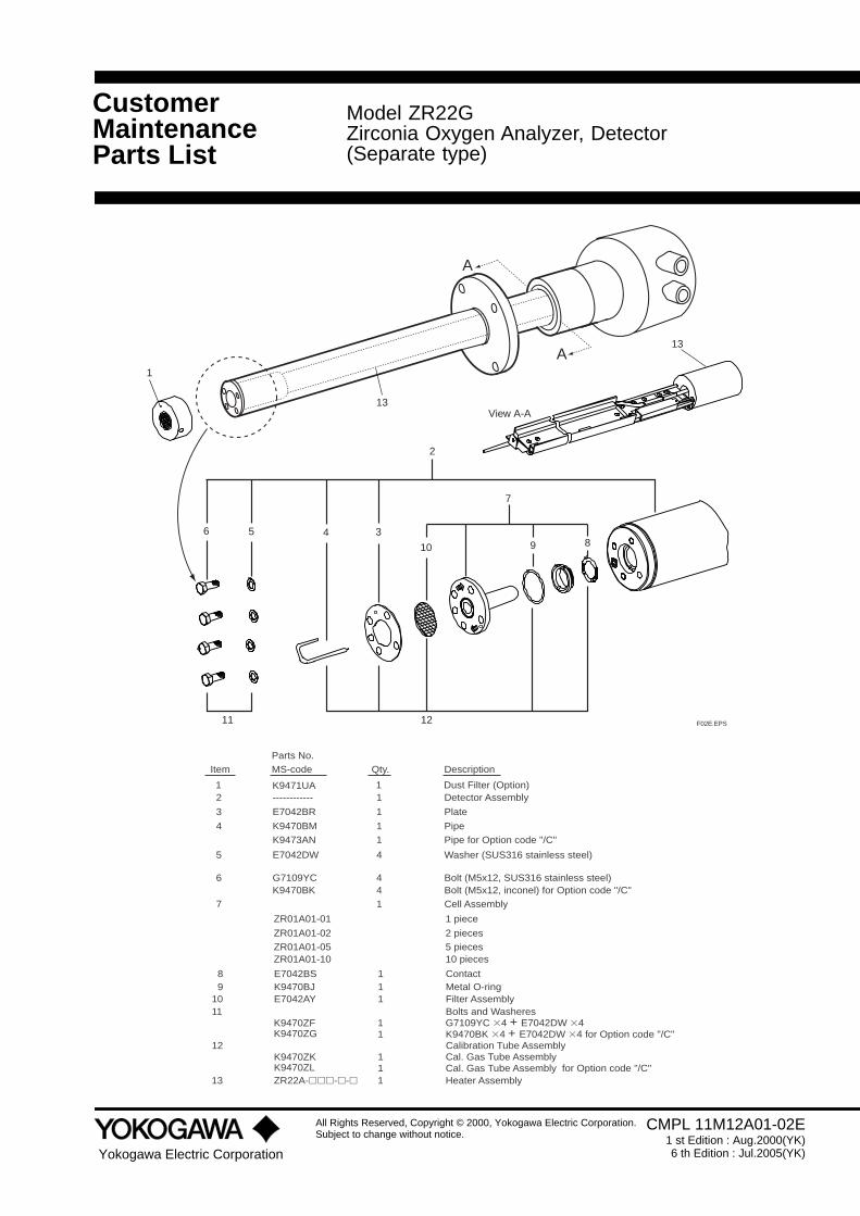
CustomerMaintenanceParts List
Yokogawa Electric Corporation
All Rights Reserved, Copyright © 2000, Yokogawa Electric Corporation.Subject to change without notice.
Model ZR22GZirconia Oxygen Analyzer, Detector(Separate type)
CMPL 11M12A01-02E1 st Edition : Aug.2000(YK)6 th Edition : Jul.2005(YK)
2
6 5 4 3
10 9 8
7
11 12 F02E.EPS
A
A13
13View A-A
1
4
4E7042DW
3
1K9470BM1K9473AN
1------------2
4G7109YC4K9470BK
6
DescriptionQty.Parts No.MS-codeItem
5
E7042BR 1
Washer (SUS316 stainless steel)
PipePipe for Option code "/C"
Detector Assembly
Bolt (M5x12, SUS316 stainless steel)Bolt (M5x12, inconel) for Option code "/C"
Plate
11 Dust Filter (Option)K9471UA
1E7042BS81K9470BJ9
ContactMetal O-ring
1E7042AY10 Filter Assembly
K9470ZFK9470ZG
11 Bolts and Washeres1 G7109YC 34 + E7042DW 34 1 K9470BK 34 + E7042DW 34 for Option code "/C"
K9470ZKK9470ZL
12 Calibration Tube Assembly1 Cal. Gas Tube Assembly 1 Cal. Gas Tube Assembly for Option code "/C"1ZR22A-hhh-h-h13 Heater Assembly
17 Cell Assembly
ZR01A01-10
ZR01A01-02ZR01A01-05
ZR01A01-01
10 pieces
2 pieces5 pieces
1 piece
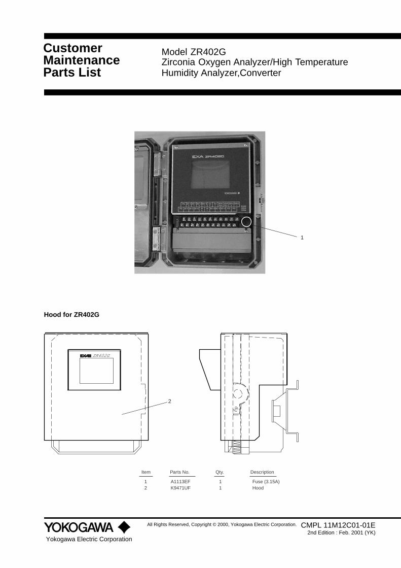
CustomerMaintenanceParts List
Yokogawa Electric Corporation
All Rights Reserved, Copyright © 2000, Yokogawa Electric Corporation.
Model ZR402GZirconia Oxygen Analyzer/High TemperatureHumidity Analyzer,Converter
CMPL 11M12C01-01E2nd Edition : Feb. 2001 (YK)
1
Hood for ZR402G
ZR402G
2
Fuse (3.15A)1A1113EF1Hood1K9471UF2
DescriptionQty.Parts No.Item

CustomerMaintenanceParts List
Yokogawa Electric Corporation
All Rights Reserved, Copyright © 2000, Yokogawa Electric Corporation. CMPL 11M12A01-11E1st Edition : Dec. 2000 (YK)
2nd Edition : Feb. 2001 (YK)
Model ZR40HSeparate type Zirconia Oxygen Analyzer/High Temperature Humidity Analyzer,Automatic Calibration Unit
LZEROLOCK OCK
SPAN IN ZERO IN
AUTO CALIBRATION UNIT
-20 TO 558C
Made in Japan
ZR40HMODELSUFFIX
STYLE
AMB.TEMP
NO.S1
SUPPLY 690kPa MAX.
USED WITHZR402G
REF.OUT CAL.OUT
ZEROSPANCOMMON
6
910
1
Item Part No. DescriptionQty
6 K9473XC Flowmeter

CustomerMaintenanceParts List
Yokogawa Electric Corporation
All Rights Reserved, Copyright © 2000, Yokogawa Electric Corporation. CMPL 11M03B01-10E1st Edition : Dec. 2000 (YK)5th Edition :Sept. 2001 (YK)
Model ZO21P-HZirconia Oxygen AnalyzerHigh Temperature Probe Adaptor
1
2
3
4 5,6
7 8,9,10
DescriptionQty.Parts No.Item
1 E7046AL 1 Probe (SiC, L=1.0m) E7046BB 1 Probe (SiC, L=1.5m) E7046AP 1 Probe (SUS, L=1.0m) E7046AQ 1 Probe (SUS, L=1.5m)
2 E7046AD 1 Probe Adaptor (for JIS 5K-50-FF)
E7046CB 1 Probe Adaptor (for ANSI CLASS150-4-RF) 1 Probe Adaptor (for DIN PN10-DN50-A) 1 Probe Adaptor (for JIS 10K-100-FF) 1 Probe Adaptor (for JIS 10K-80-FF) 1 Probe Adaptor (for JIS 10K-65-FF)
1 Probe Adaptor (for ANSI CLASS150-3-RF) 1 Probe Adaptor (for ANSI CLASS150-2 1/2-RF) 1 Probe Adaptor (for JPI CLASS150-4-RF) 1 Probe Adaptor (for JPI CLASS150-3-RF)
3 E7046AC 1 Gasket
4 E7046AB 1 Plate 5 G7030YC 4 Bolt 6 Y9800WU 8 Washer 7 G7073XL 1 Gasket 8 Y9630RU 4 Bolt
9 Y9121BU 4 Nut10 Y9120WU 4 Washer
ZR22G
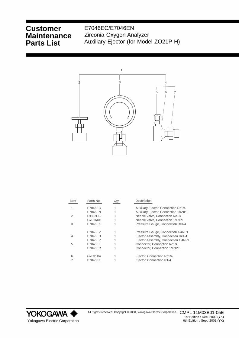
CustomerMaintenanceParts List
Yokogawa Electric Corporation
All Rights Reserved, Copyright © 2000, Yokogawa Electric Corporation. CMPL 11M03B01-05E1st Edition : Dec. 2000 (YK)
6th Edition : Sept. 2001 (YK)
E7046EC/E7046ENZirconia Oxygen AnalyzerAuxiliary Ejector (for Model ZO21P-H)
1
2 3 4
5 6 7
DescriptionQty.Parts No.Item
1 E7046EC 1 Auxiliary Ejector, Connection Rc1/4 E7046EN 1 Auxiliary Ejector, Connection 1/4NPT
2 L9852CB 1 Needle Valve, Connection Rc1/4 G7016XH 1 Needle Valve, Connection 1/4NPT3 E7046EK 1 Pressure Gauge, Connection Rc1/4
E7046EV 1 Pressure Gauge, Connection 1/4NPT4 E7046ED 1 Ejector Assembly, Connection Rc1/4 E7046EP 1 Ejector Assembly, Connection 1/4NPT5 E7046EF 1 Connector, Connection Rc1/4 E7046ER 1 Connector, Connection 1/4NPT
6 G7031XA 1 Ejector, Connection Rc1/47 E7046EJ 1 Ejector, Connection R1/4

CustomerMaintenanceParts List
Yokogawa Electric Corporation
© Copyright 2000(YK). 3rd Edition: Dec. 2000 (YK)
Model ZO21SZirconia Oxygen Analyzer/ High TemperatureHumidity Analyzer, Standard Gas Unit
CMPL 11M3D1-01E
111
Item Part No. DescriptionQty
123
2
E7050BAE7050BJ
Pump (see Table 1)Zero Gas Cylinder (x6 pcs)Needle Valve
Power Pump
AC 100V110115
E7050AU
E7050AVAC 200V
220240
Table 1

Revision Record
Manual Title : Model ZR22G, ZR402G Separate type Zirconia Oxygen Analyzer
Manual Number : IM 11M12A01-02E
Edition Date Remark (s)
1st Oct. 2000 Newly published
2nd Mar. 2001 Revised section
1.1.3 “System 3” explanation changed
2.2 In “General-use Separate-type Detector”, some MS codes changed
2.4 Corrected errors in ZR402G External Dimensions figure, changed MS Code table
2.5.1 Changed reference air pressure where check valves is used, style changed of ZA8F
2.5.2 Added detail about ZR40H Automatic Calibration Unit
2.7.3 Added items to figure of Auxiliary Ejector for High Temperature
3.2.2 Corrected Figure 3.6 Panel Cutout, Figure 3.13 Mounting Holes
3.5 Added to 3.5 Installation of ZR40H Automatic Calibration Unit
6.1 Added Filter to 6.1 ZR22G Detector
6.3 Added Names and Functions to 6.3 ZR40H Automatic Calibration Unit
7.2 Changed reference air pressure where check valve is used
7.12.2.1 Changed reference air pressure where check valve is used
10.1.1.6 Corrected Table 10.1
10.6.1 Changed reference air pressure where check valve is used
11.1 Added Filter to 11.1 Inspection and Maintenance of the Detector Added Filter to
CMPL11M12A01-02E, and added ZR40H Automatic Calibration Unit to CMPL11M12A01-11E
3rd Sept. 2001 Revised section
1.2 Model ZR22A Heater Assembly added
2.5.1 ZA8F Flow Setting Unit error corrected
2.7.9 Model ZR22A Heater Assembly added
8.5.1 Table 8.7 Input Contact Functions changed
10.1.5 “French” added to Language Selection
11.1.3 Reference document added to Replacement of the Heater Unit
Heater Assembly added to CMPL 11M12A01-02E
CMPL11M03B01-05E revised to 6th Edtion, some part No. changed.
CMPL11M03B01-10E revised to 5th Edtion, some part deleted.
4th July.2003 Style of model ZR22G and ZR22A changed to S2
Notation of flange specification unified
Dust guard protector, Airset added
CMPL 11M12A01-02E Cell some parts no. changed, revised to 5th edition.
CMPL 11M03B01-05E some parts no. changed, revised to 6th edition.
5th Dec.2003 Changes of related by ROM and Main Board Assembly changed.
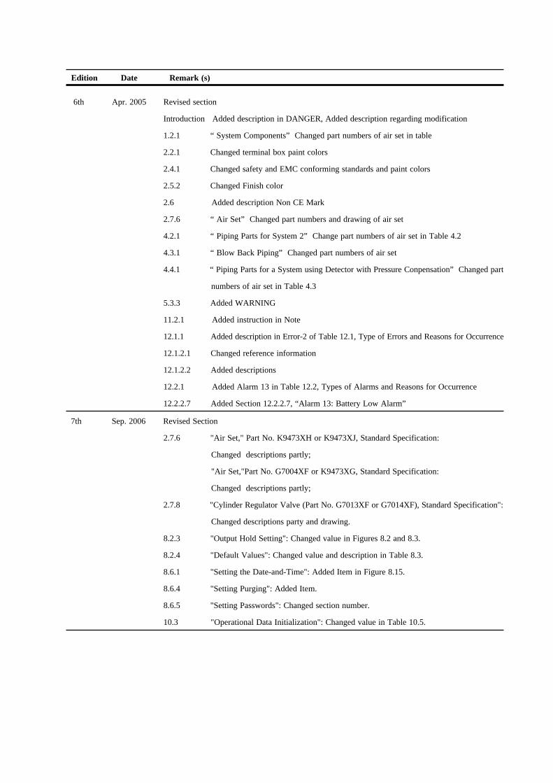
Edition Date Remark (s)
6th Apr. 2005 Revised section
Introduction Added description in DANGER, Added description regarding modification
1.2.1 “ System Components” Changed part numbers of air set in table
2.2.1 Changed terminal box paint colors
2.4.1 Changed safety and EMC conforming standards and paint colors
2.5.2 Changed Finish color
2.6 Added description Non CE Mark
2.7.6 “ Air Set” Changed part numbers and drawing of air set
4.2.1 “ Piping Parts for System 2” Change part numbers of air set in Table 4.2
4.3.1 “ Blow Back Piping” Changed part numbers of air set
4.4.1 “ Piping Parts for a System using Detector with Pressure Conpensation” Changed part
numbers of air set in Table 4.3
5.3.3 Added WARNING
11.2.1 Added instruction in Note
12.1.1 Added description in Error-2 of Table 12.1, Type of Errors and Reasons for Occurrence
12.1.2.1 Changed reference information
12.1.2.2 Added descriptions
12.2.1 Added Alarm 13 in Table 12.2, Types of Alarms and Reasons for Occurrence
12.2.2.7 Added Section 12.2.2.7, “Alarm 13: Battery Low Alarm”
7th Sep. 2006 Revised Section
2.7.6 "Air Set," Part No. K9473XH or K9473XJ, Standard Specification:
Changed descriptions partly;
"Air Set,"Part No. G7004XF or K9473XG, Standard Specification:
Changed descriptions partly;
2.7.8 "Cylinder Regulator Valve (Part No. G7013XF or G7014XF), Standard Specification":
Changed descriptions party and drawing.
8.2.3 "Output Hold Setting": Changed value in Figures 8.2 and 8.3.
8.2.4 "Default Values": Changed value and description in Table 8.3.
8.6.1 "Setting the Date-and-Time": Added Item in Figure 8.15.
8.6.4 "Setting Purging": Added Item.
8.6.5 "Setting Passwords": Changed section number.
10.3 "Operational Data Initialization": Changed value in Table 10.5.