user’s manual - scadapro.com to scada pro 2 note this manual, ... introduction to scada pro 9 ......
TRANSCRIPT

User’s Manual
⓿Introduction

INTRODUCTION TO SCADA Pro
2
Note
This manual, along with all the training material of Scada Pro, aim solely to act as a guide for the proper use of the application. Solid engineering knowledge in conjunction with the technical legislation are considered as essential prerequisites.
Acknowledgments
ACE-Hellas would like to thank the R&D, the design and the commercial teams whose collaboration resulted in this manual. Special thanks are due to our colleagues Ms. Amalia Bagourdi-Degleri and Mr. Ioannis Kalyviotis for their significant contributions in writing and reviewing this manual.
Version SCADA Pro
September 2016

INTRODUCTION TO SCADA Pro
3
CONTENTS
CONTENTS ....................................................................................................................................... 3
I. THE COMPANY ..................................................................................................................... 5
II. PROGRAM GENERAL INFORMATION ................................................................................... 5
III. INTRODUCTION TO SCADA Pro ........................................................................................... 6
IV. GENERAL DESCRIPTION OF THE NEW INTERFACE ............................................................. 10
V. DETAILED DESCRIPTION OF THE NEW INTERFACE ............................................................ 13
1. FILE .................................................................................................................................... 13
2. QUICK ACCESS TOOLBAR ................................................................................................... 17
3. UNITS ................................................................................................................................. 18
3.1. Basic .............................................................................................................................. 18
3.2. Modeling ...................................................................................................................... 18
3.3. View .............................................................................................................................. 18
3.4. Tools ............................................................................................................................. 19
3.5. Slabs ............................................................................................................................. 19
3.6. Loads ............................................................................................................................ 19
3.7. Analysis ......................................................................................................................... 20
3.8. Post - Processor ............................................................................................................ 20
3.9. Members Design .......................................................................................................... 20
3.10. Drawings - Detailing ..................................................................................................... 20
3.11. Addons.......................................................................................................................... 21
4. MANAGEMENT BAR .......................................................................................................... 22
4.1. Style .............................................................................................................................. 22
4.2. Activate Product ........................................................................................................... 22
4.3. Language ...................................................................................................................... 23
4.4. About ............................................................................................................................ 24
5. TREE ................................................................................................................................... 25

INTRODUCTION TO SCADA Pro
4
6. OSNAP, ZOOM, SELECT, UNDO .......................................................................................... 27
6.1. Osnap Toolbar .............................................................................................................. 27
6.2. Zoom Toolbar ............................................................................................................... 29
6.3. Select Toolbar ............................................................................................................... 30
6.4. Undo-Redo ................................................................................................................... 32
6.5. Match Properties .......................................................................................................... 32
7. PROPERTIES ....................................................................................................................... 34
8. PARAMETERS - DATA ......................................................................................................... 36
9. STATUS BAR ....................................................................................................................... 37
10. COLOR ................................................................................................................................ 38

INTRODUCTION TO SCADA Pro
5
I. THE COMPANY
ACE-Hellas SA (www.ace-hellas.gr), established in 1979 and a member of Quest’s group of companies since 1999, is today one of the most innovative providers of information and communications technology (ICT) solutions in the market and a leading developer of structural design, engineering and sustainability software solutions.
A series of acquisitions, strategic partnerships and investments have enabled ACE-Hellas to become one of the fastest growing hi-tech solution providers, with deep knowledge of the European market, strong know-how and solid financial structure.
Being a strategic partner with the largest companies worldwide (Apple, Dell, HP, Contex, Microsoft, Autodesk and others) has enabled the company to grow a customer portfolio with over 7.500 enterprises in South-East Europe.
The early adoption and implementation of Eurocodes have provided ACE-Hellas tremendous experience in producing superior quality results that meet all European and local regulations.
ACE-Hellas’ mission is to develop software tools that enable people to build their ideas and bring them to life!
The strategy aims to provide our customers with end-to-end business solutions designed to take advantage of the capabilities new technologies offer in order to build a safer world, build it with speed, while preserving resources.
The long-standing success of ACE-Hellas in the technical business ecosystem is due to its continued growth and expansion through innovation, and its ability to build strong relationship with customers and partners based on trust & respect.
SCADA Pro, is the ultimate platform for integrated structural analysis and design.
II. PROGRAM GENERAL INFORMATION
The innovative and revolutionary SCADA Pro is a leading sostware for the analysis and design of
structures. By designing according to your needs and incorporating cutting edge technologies based on 30 years of continuous research and development, SCADA Pro provides all the tools for quick and easy creation of accurate, reliable and supervisory models of your structures. Using automated processes, your architectural designs are converted, with a single click, into a three-dimensional numerical model ready for analysis and design.
SCADA Pro includes the state of the art of solvers for all types of analyses (linear or nonlinear) and covers all code provisions and regulations applicable in most European countries and Saudi Building Code (SBC). It combines truss, beams 2D and 3D, plane, plate and shell finite elements in the same spatial model with unlimited number of nodes and finite elements. Tested by thousands of engineers around the world, it has been considered to be one of the most reliable, comprehensive and productive software for analyzing and designing any type of structure of every structural material (Reinforced Concrete, Steel, Masonry, Timber).
SCADA Pro is a program constantly upgrading, evolving and adapting. The technical department of ACE-Hellas, in permanent cooperation with the National Technical University of Athens, ensures the continuous development and updating.
INTRODUCTION TO SCADA Pro
6
III. INTRODUCTION TO SCADA Pro
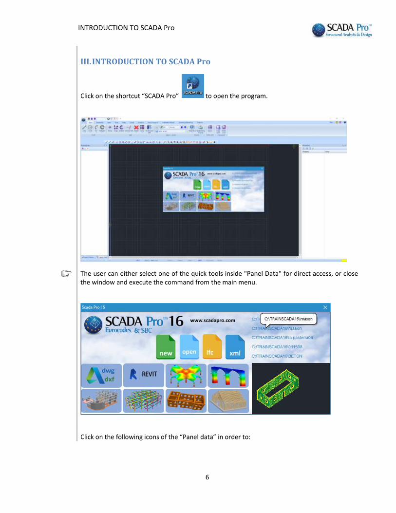
Click on the shortcut “SCADA Pro” to open the program.
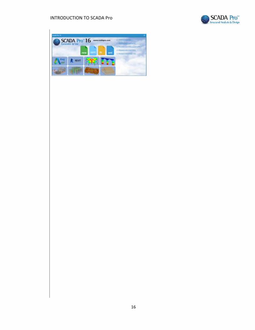
The user can either select one of the quick tools inside "Panel Data" for direct access, or close the window and execute the command from the main menu.
Click on the following icons of the “Panel data” in order to:

INTRODUCTION TO SCADA Pro
7
Create a new file
Open an existing file
Read an ifc Revit Autodesk design file
By using appropriate libraries, SCADA Pro automatically recognizes all the structural elements (columns, beams, slabs, etc.) with their respective properties, generating in this way a model which is ready for the analysis.
Read an xml file
Import a cad file and use it as an auxiliary file into the interface or base for Automatic Level Creation and Automatic Section Identification.
Detailed description of the automatic procedure based on the acad files is given in the concrete structure example.

INTRODUCTION TO SCADA Pro
8
Read an xml Revit Autodesk design file
Τemplates
Automatically create concrete, steel, masonry, timber structures as well as to create 2D and 3D finite elements by clicking on the following icons:
Create a reinforced concrete structure
Create a steel structure
Create a masonry structure
Create a timber structure
Create a new project with 2D surface finite element
Create a new project with 3D surface finite element
The same commands are also located in SCADA Pro main menu. Detailed definition of these commands can be found on subsequent chapters (Chapter 2 “Modelling”).

INTRODUCTION TO SCADA Pro
9
Start Screen Preview
Preview existing files from the start screen.
List of the 4 most recent files.
Pointing the mouse on the file name displays the path. Single click to preview, double to open.
When a new file is created, the General Parameter window is displayed in the interface enabling the user to set in advance parameters like the Material, the Regulation, the Project General Information and other parameters such as the Autosave time interval.
Detailed definition of these parameters can be found on subsequent chapters (Chapter 11 “Addons”).
INTRODUCTION TO SCADA Pro
10
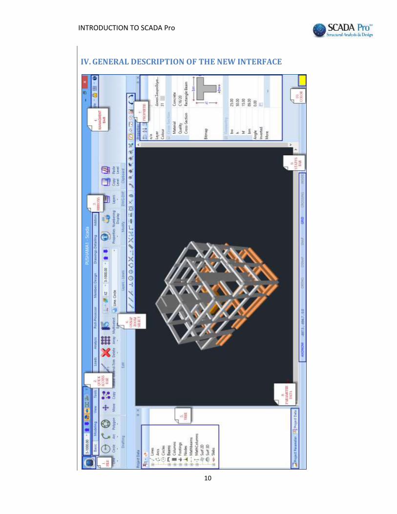
IV. GENERAL DESCRIPTION OF THE NEW INTERFACE
INTRODUCTION TO SCADA Pro
11
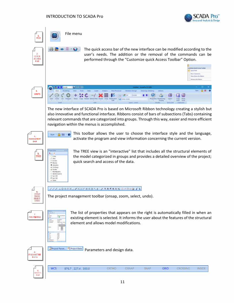
File menu
The quick access bar of the new interface can be modified according to the user’s needs. The addition or the removal of the commands can be performed through the “Customize quick Access Toolbar” Option.
The new interface of SCADA Pro is based on Microsoft Ribbon technology creating a stylish but also innovative and functional interface. Ribbons consist of bars of subsections (Tabs) containing relevant commands that are categorized into groups. Through this way, easier and more efficient navigation within the menus is accomplished.
This toolbar allows the user to choose the interface style and the language, activate the program and view information concerning the current version.
The TREE view is an "interactive" list that includes all the structural elements of the model categorized in groups and provides a detailed overview of the project; quick search and access of the data.
The project management toolbar (onsap, zoom, select, undo).
The list of properties that appears on the right is automatically filled in when an existing element is selected. It informs the user about the features of the structural element and allows model modifications.
Parameters and design data.

INTRODUCTION TO SCADA Pro
12
The status bar at the bottom of the screen can be adjusted according to both the selected unit and the view of the structure (2D/3D), providing extra management features.
Click to select the color of a new element, different from the default one. Use during the virtual view to show the structure with realistic material colors (gray = concrete, blue = steel, brown = masonry, beige =timber).

INTRODUCTION TO SCADA Pro
13
V. DETAILED DESCRIPTION OF THE NEW INTERFACE
1. FILE
Start a new project. In the dialog box that appears, specify the details of the new project. More specifically, type a name in the "Name" field.
The file name should be up to 8 characters without spaces and special characters (i.e. /, -, _). In the "Info" field additional information may be included and under the "Location" field the path of the project is specified. The program automatically creates a folder with this name that contains subfolders, ready to be filled in with all of the project’s data. The subfolders created are listed in the following.

INTRODUCTION TO SCADA Pro
14
scanal: analysis files
scades_c: design files of concrete structural elements
scades_Sid: design files of steel structural elements
scades_Synd: design files of the steel connections
scainp: input files of the linear structural elements (i.e. beams, columns)
and the slabs
scapush: pushover analysis files
scatmp: temporary files
tmp: temporary files
project.inf: data base information
Open an existing project by selecting the file from the list.
Close a project without closing the application. SCADA Pro remains open for opening another existing project or creating a new one.
Select recent documents for quick access and preview.
Save the active project with its current file name, location and file format. The initially created project is automatically updated.
Additional ability to automatically save the project at specified time intervals (Autosave).
To save an active project file with a different name.
INTRODUCTION TO SCADA Pro
15
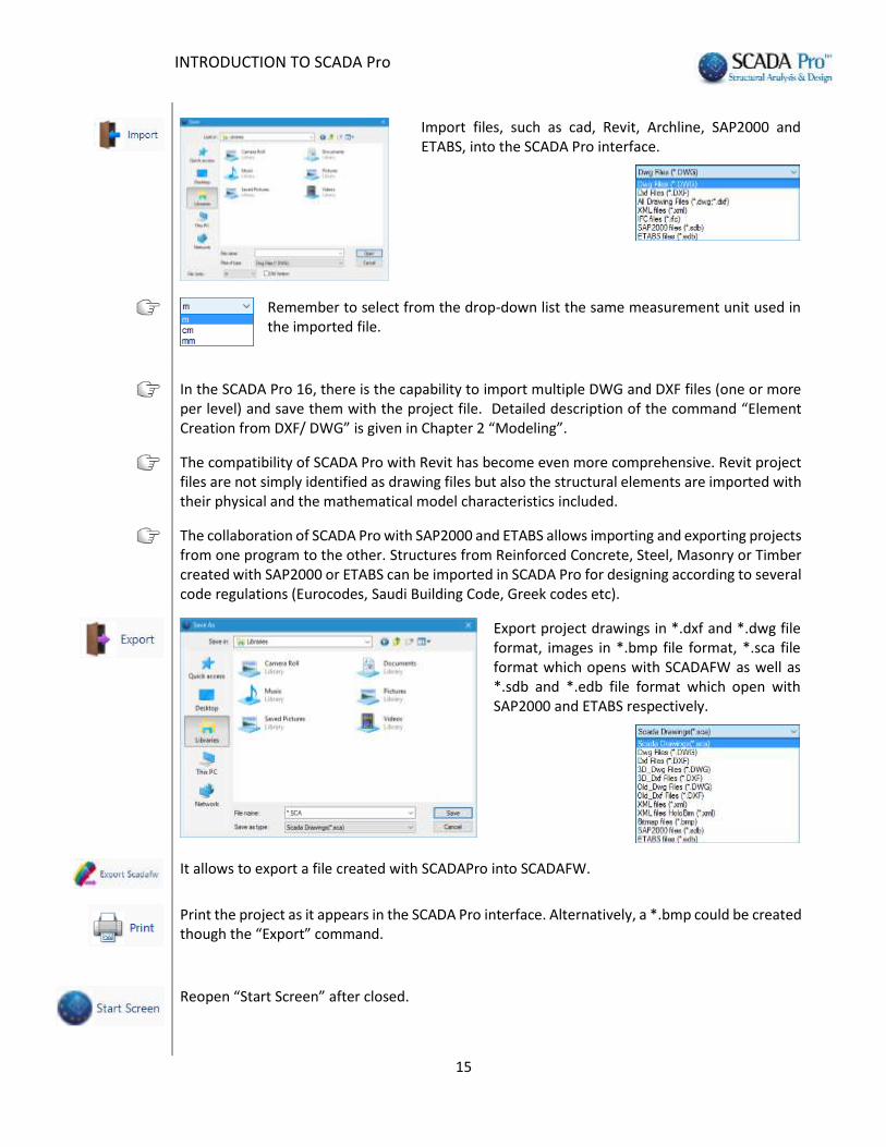
Import files, such as cad, Revit, Archline, SAP2000 and ETABS, into the SCADA Pro interface.
Remember to select from the drop-down list the same measurement unit used in the imported file.
In the SCADA Pro 16, there is the capability to import multiple DWG and DXF files (one or more per level) and save them with the project file. Detailed description of the command “Element Creation from DXF/ DWG” is given in Chapter 2 “Modeling”.
The compatibility of SCADA Pro with Revit has become even more comprehensive. Revit project files are not simply identified as drawing files but also the structural elements are imported with their physical and the mathematical model characteristics included.
The collaboration of SCADA Pro with SAP2000 and ETABS allows importing and exporting projects from one program to the other. Structures from Reinforced Concrete, Steel, Masonry or Timber created with SAP2000 or ETABS can be imported in SCADA Pro for designing according to several code regulations (Eurocodes, Saudi Building Code, Greek codes etc).
Export project drawings in *.dxf and *.dwg file format, images in *.bmp file format, *.sca file format which opens with SCADAFW as well as *.sdb and *.edb file format which open with SAP2000 and ETABS respectively.
It allows to export a file created with SCADAPro into SCADAFW.
Print the project as it appears in the SCADA Pro interface. Alternatively, a *.bmp could be created though the “Export” command.
Reopen “Start Screen” after closed.
INTRODUCTION TO SCADA Pro
16
INTRODUCTION TO SCADA Pro
17
2. QUICK ACCESS TOOLBAR
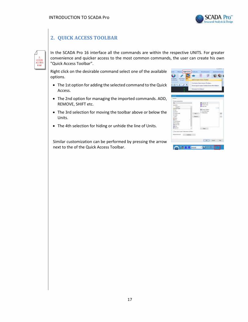
In the SCADA Pro 16 interface all the commands are within the respective UNITS. For greater convenience and quicker access to the most common commands, the user can create his own "Quick Access Toolbar".
Right click on the desirable command select one of the available options.
The 1st option for adding the selected command to the Quick Access.
The 2nd option for managing the imported commands. ADD, REMOVE, SHIFT etc.
The 3rd selection for moving the toolbar above or below the Units.
The 4th selection for hiding or unhide the line of Units.
Similar customization can be performed by pressing the arrow next to the of the Quick Access Toolbar.

INTRODUCTION TO SCADA Pro
18
3. UNITS
In SCADA Pro 16 interface, all the commands are grouped in eleven UNITS.
Detailed description of each UNIT is given in the respective chapter of the manual.
3.1. Basic
The "Basic" UNIT includes the six following Tabs:
Draft
Edit
Layers-Levels
Modify
DWG-DXF
Clipboard
3.2. Modeling
The “Modeling” UNIT includes the seven following Tabs:
Column
Beam
Foundation
Surface elements
Elements
Add-ons
Libraries
3.3. View
The “View” UNIT includes the four following Tabs:
Zoom
Display

INTRODUCTION TO SCADA Pro
19
Views
Dynamic Section
3.4. Tools
The “Tools” UNIT includes the six following Tabs:
Structural elements
UCS-WCS
Model
Members
Nodes
Various
3.5. Slabs
The “Slabs” UNIT includes the four following 4 Tabs:
Insert
Edit
Strips
Checks
3.6. Loads
The “Loads” UNIT includes the four following Tabs:
Definition
Slab Loads
Member Loads
Wind – Snow Loads
INTRODUCTION TO SCADA Pro
20
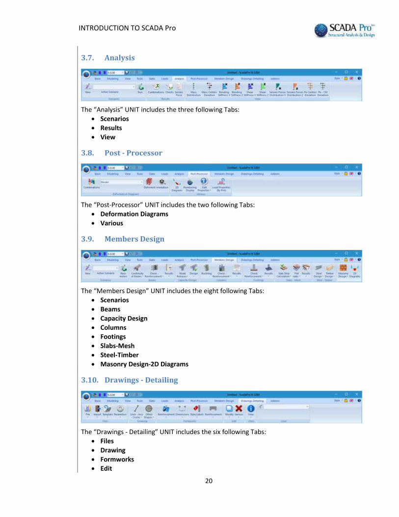
3.7. Analysis
The “Analysis” UNIT includes the three following Tabs:
Scenarios
Results
View
3.8. Post - Processor
The “Post-Processor” UNIT includes the two following Tabs:
Deformation Diagrams
Various
3.9. Members Design
The “Members Design” UNIT includes the eight following Tabs:
Scenarios
Beams
Capacity Design
Columns
Footings
Slabs-Mesh
Steel-Timber
Masonry Design-2D Diagrams
3.10. Drawings - Detailing
The “Drawings - Detailing” UNIT includes the six following Tabs:
Files
Drawing
Formworks
Edit
INTRODUCTION TO SCADA Pro
21
View
Level
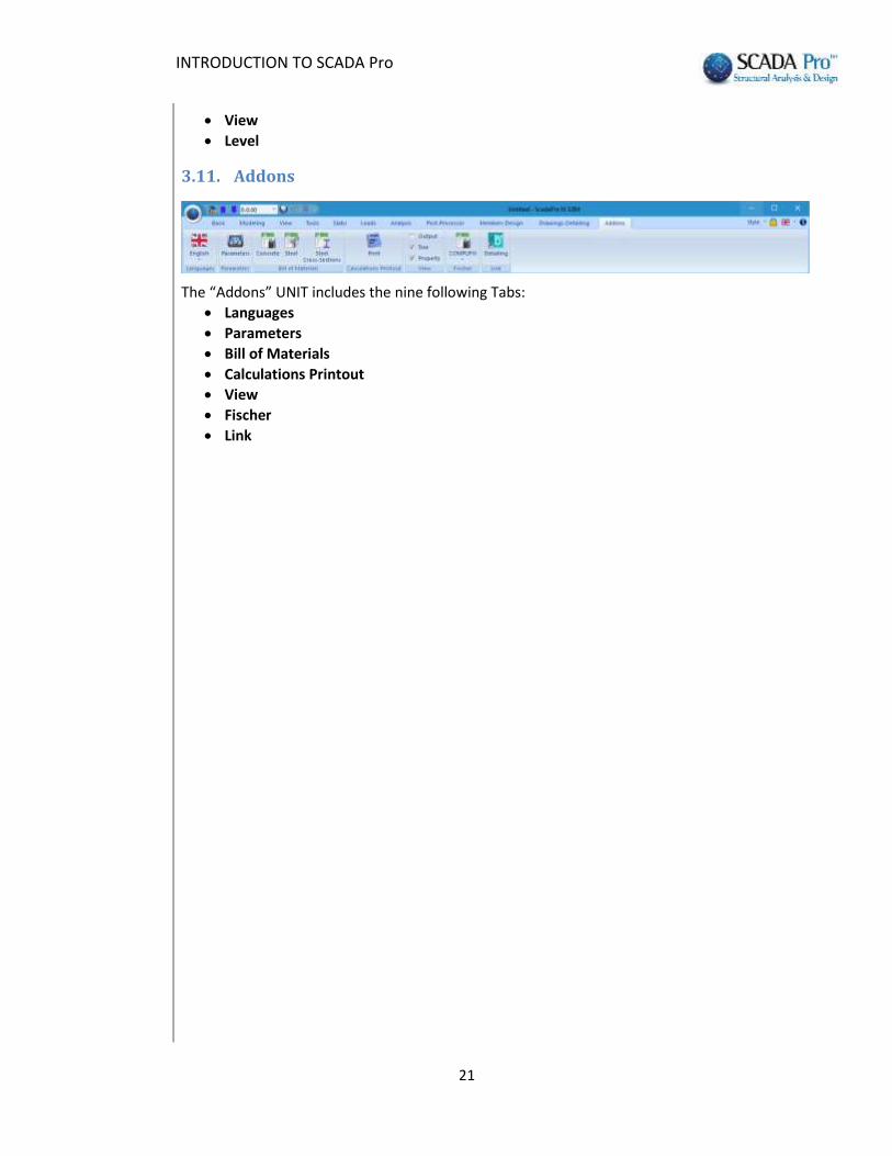
3.11. Addons
The “Addons” UNIT includes the nine following Tabs:
Languages
Parameters
Bill of Materials
Calculations Printout
View
Fischer
Link
INTRODUCTION TO SCADA Pro
22
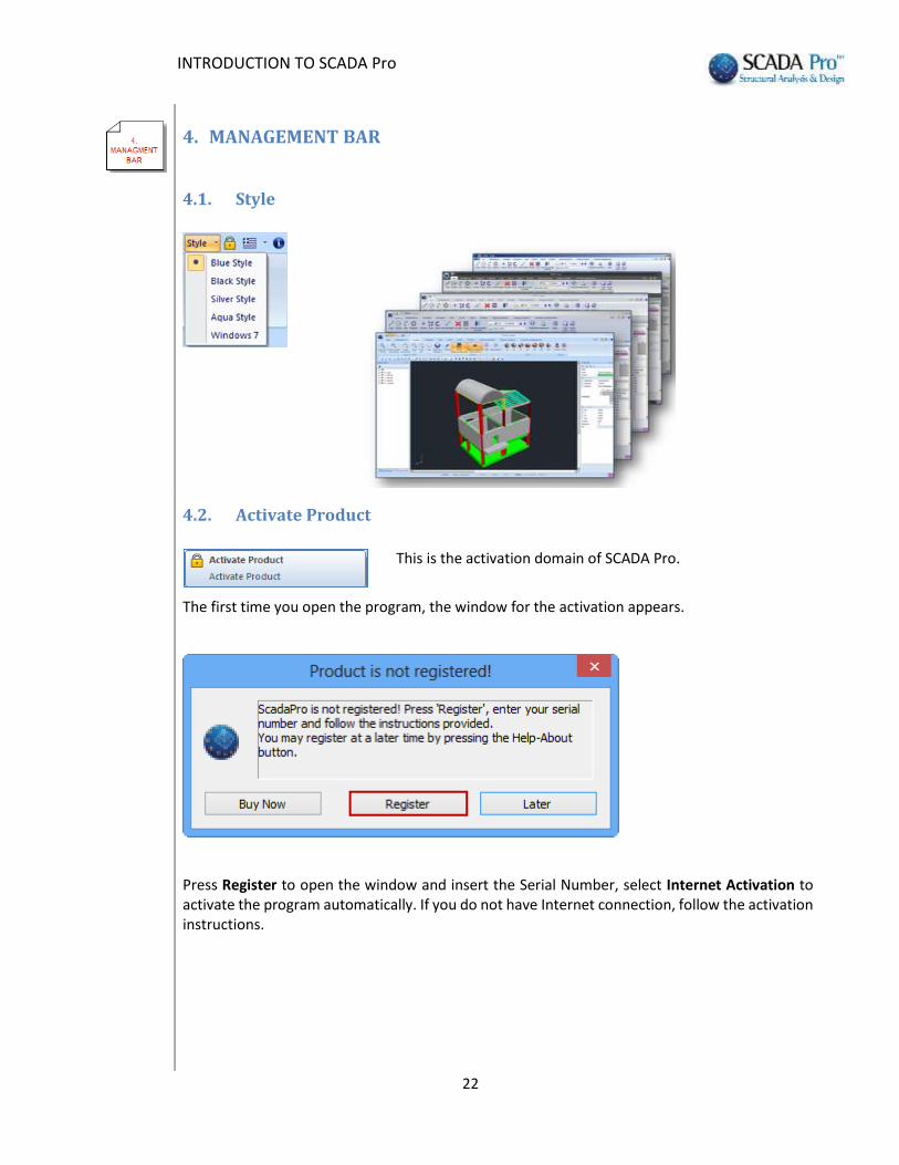
4. MANAGEMENT BAR
4.1. Style
4.2. Activate Product
This is the activation domain of SCADA Pro.
The first time you open the program, the window for the activation appears.
Press Register to open the window and insert the Serial Number, select Internet Activation to activate the program automatically. If you do not have Internet connection, follow the activation instructions.

INTRODUCTION TO SCADA Pro
23
4.3. Language
The new upgraded version of SCADA Pro includes 8 languages with automatic switch from one to another.
Select the language from the list. Interface, elements, norms and all the documents will be generated in the selected language.
The default language at the beginning of the program depends on the default language of the Windows operating system. By changing the language (either through "Management Bar" or the “Add-ons" UNIT) SCADA Pro temporarily closes and it re-opens in the selected language.
Files can be opened in all languages independently. You can start a file in one language and complete it in a different one.

INTRODUCTION TO SCADA Pro
24
4.4. About
This command is used for learning about the features of the program and the version number.
SCADA Pro is updated automatically if the user is connected to internet. When opening the program, a message appears in case of a new update. Allow updating and continue your work undisturbed.
INTRODUCTION TO SCADA Pro
25
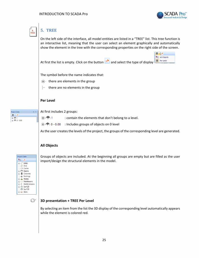
5. TREE
On the left side of the interface, all model entities are listed in a “TREE” list. This tree function is an interactive list, meaning that the user can select an element graphically and automatically show the element in the tree with the corresponding properties on the right side of the screen.
At first the list is empty. Click on the button and select the type of display
The symbol before the name indicates that:
there are elements in the group
there are no elements in the group
Per Level
At first includes 2 groups:
: contain the elements that don’t belong to a level.
: Includes groups of objects on 0 level
As the user creates the levels of the project, the groups of the corresponding level are generated.
All Objects
Groups of objects are included. At the beginning all groups are empty but are filled as the user import/design the structural elements in the model.
3D presentation + TREE Per Level
By selecting an item from the list the 3D display of the corresponding level automatically appears while the element is colored red.

INTRODUCTION TO SCADA Pro
26
By right click on an item from the TREE a command list related to the type of the item opens.

INTRODUCTION TO SCADA Pro
27
6. OSNAP, ZOOM, SELECT, UNDO
Toolbar of drawing management (osnap, zoom, select, undo).
IMPORTANT NOTES:
In SCADA Pro the command is selected prior to the selection of the elements through the OSNAP & SELECT options.
To cancel a command use the “Esc” button or the right mouse button.
6.1. Osnap Toolbar
The nine first commands and the 16th command activate the following snap points:
edge
middle
nearest
vertical
tangent
intersection
Firstly, select the span and afterwards click on the first line (beam or column) and then on the second line. The intersection point is the “x” point. Note that intersection of two beams or the edges of columns etc. may also be considered as intersection points.
projection
With this command the projection of a point onto a specific line is located. Firstly, select the point of interest and then select the line to be projected to. The projection of the line
is the “ ” point.
column vertices
parallel to
Use this command to create a new object (line or beam) parallel to a line. Define the first point of the new object and afterwards click on the osnap command. By hovering the cursor over the line the second point is displayed.
INTRODUCTION TO SCADA Pro
28
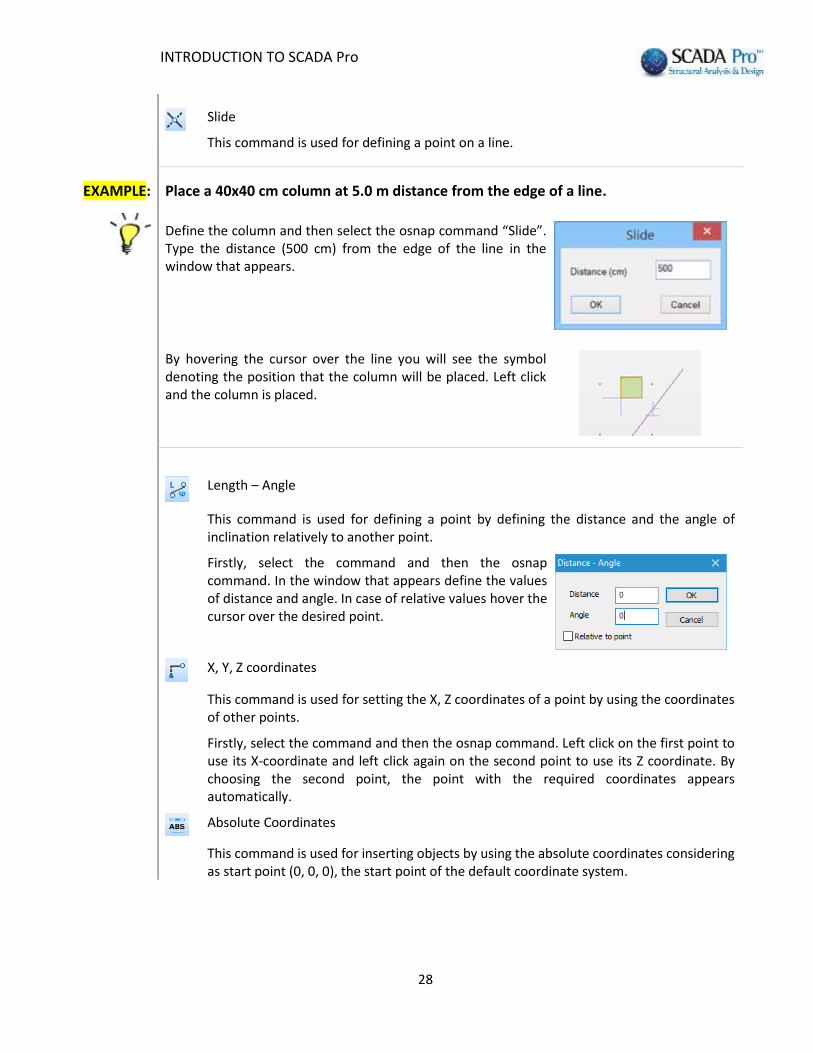
Slide
This command is used for defining a point on a line.
EXAMPLE:
Place a 40x40 cm column at 5.0 m distance from the edge of a line.
Define the column and then select the osnap command “Slide”. Type the distance (500 cm) from the edge of the line in the window that appears.
By hovering the cursor over the line you will see the symbol denoting the position that the column will be placed. Left click and the column is placed.
Length – Angle
This command is used for defining a point by defining the distance and the angle of inclination relatively to another point.
Firstly, select the command and then the osnap command. In the window that appears define the values of distance and angle. In case of relative values hover the cursor over the desired point.
X, Y, Z coordinates
This command is used for setting the X, Z coordinates of a point by using the coordinates of other points.
Firstly, select the command and then the osnap command. Left click on the first point to use its X-coordinate and left click again on the second point to use its Z coordinate. By choosing the second point, the point with the required coordinates appears automatically.
Absolute Coordinates
This command is used for inserting objects by using the absolute coordinates considering as start point (0, 0, 0), the start point of the default coordinate system.

INTRODUCTION TO SCADA Pro
29
In the dialog box type the X, Y and Z coordinates.
The Y coordinate is optional. If you keep value 0, the point gets the altitude of the current level.
Relative Coordinates
This command is used for inserting points relative to another point. This point can be the previous inserted point or any other point.
EXAMPLE:
Place a 40x40 cm column at x=3.0 m end y=5.0 m distance from a point.
Define the column and select the command “Relative Coordinates”.
In the dialog box, type Χ and Ζ coordinates considering that these coordinates belong to a coordinate system with start point (0, 0) the relative point and axes the absolute axes. Then click the “ΟΚ” button.
Activate the checkbox to define a relative point with left click or deactivate it in order to consider as relative point the previous inserted point.
None
This command is used for cancelling the osnap command.
Coordinate Lock
This command is used for locking all the coordinates.
6.2. Zoom Toolbar
The following commands are used for better visualization of the interface.
Redraw
This command is used for regenerating the drawing.
Zoom Window
This command is used for displaying an area specified by a rectangular window.

INTRODUCTION TO SCADA Pro
30
Zoom Limits
This command is used for displaying the maximum extents of all objects.
Zoom Previous
Zoom In
Zoom Out
Pan
This command is used for shifting the view with the same viewing direction and magnification.
6.3. Select Toolbar
Activate each command of the select toolbar with left click:
Select objects individually
Select objects that are intersected by a polyline
Select objects that are included in an area specified by a rectangular window
Select objects that are included in an area specified by a polygon
IMPORTANT NOTES:
In the Status Bar, when “Crossing” is inactive , the objects intersected by the window
or polygon will not be selected. On the contrary, when it is active , they will be included
in the selection, with respect to the following options . Click to activate or deactivate the commands.
Select Group-Number
This command is used for selecting objects based on their common characteristics.

INTRODUCTION TO SCADA Pro
31
Activate the checkbox “Material” or “Type”, “Element Type”, “Member Type”, “Layer”, “Preference”, “Color” and from the corresponding lists select the common characteristic.
To select a color, you can choose directly from the palette or enter the corresponding ID number of the color you desire.
Then click on the button to display on the white box of the right side all the
elements with the specific characteristic. Click on button and the selected items will appear in the screen with a dashed line.
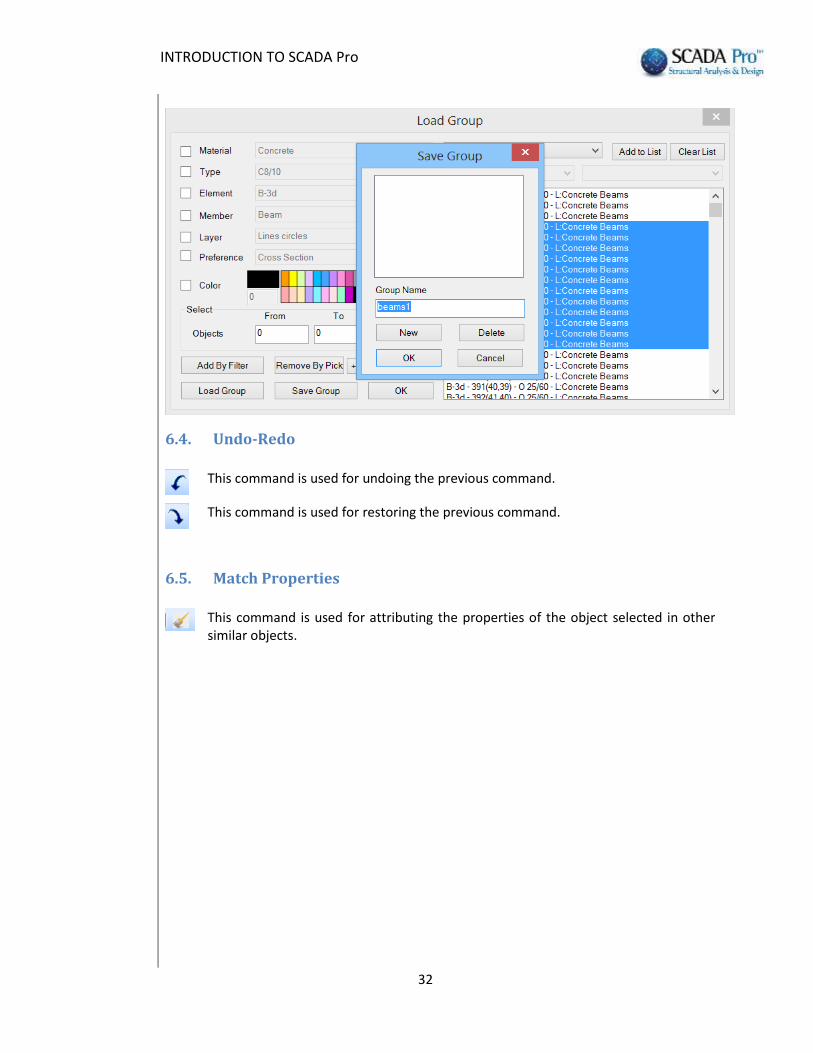
Select a group from the list on the right and click on the button to display them
on the white box of the right side. Click on the button to clear the box or select
some elements and then click on the button to remove only those.
The button enables the user to create groups of elements based on this criteria. The elements that belong to an already created group can be displayed by
clicking on the button .
INTRODUCTION TO SCADA Pro
32
6.4. Undo-Redo
This command is used for undoing the previous command.
This command is used for restoring the previous command.
6.5. Match Properties
This command is used for attributing the properties of the object selected in other similar objects.
INTRODUCTION TO SCADA Pro
33
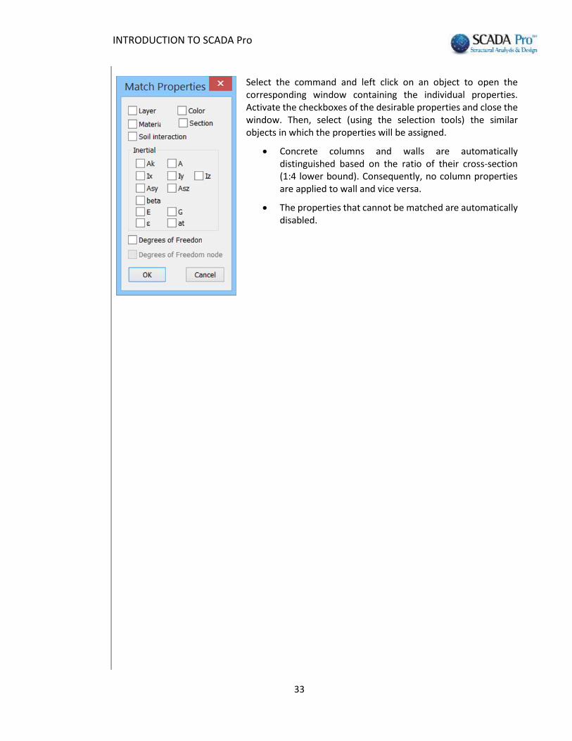
Select the command and left click on an object to open the corresponding window containing the individual properties. Activate the checkboxes of the desirable properties and close the window. Then, select (using the selection tools) the similar objects in which the properties will be assigned.
Concrete columns and walls are automatically distinguished based on the ratio of their cross-section (1:4 lower bound). Consequently, no column properties are applied to wall and vice versa.
The properties that cannot be matched are automatically disabled.

INTRODUCTION TO SCADA Pro
34
7. PROPERTIES
In the SCADA Pro 16 interface the Properties list appears on the right, informing the user about the features and allowing changes to be made.
The list is filled in automatically while selecting:
an element from the interface
an element of a subgroup in the TREE
the command “Properties” within the “Basic” UNIT
Detailed description of the lists of Properties is given in the respective chapter of the manual.
Additionally:
Selecting a mathematical member, the characteristics of the corresponding physical element appear in “Properties” list.

INTRODUCTION TO SCADA Pro
35
In a surface modeled with surface elements, the user can choose individual elements and explore their properties.
Selecting a slab (from the TREE or with right click on the slab area when the “Slabs” UNIT is active), its characteristics appear in “Properties” list.

INTRODUCTION TO SCADA Pro
36
8. PARAMETERS - DATA
This command is used for displaying the project’s parameters or the TREE.
The list “Project Parameters” will be activated on the next version.

INTRODUCTION TO SCADA Pro
37
9. STATUS BAR
The status bar at the bottom of the screen, is adjusted according to the selected UNIT and the display of the project (2d/3d), providing extra management features of the project.
2D view:
3D view: Display consecutively the Mathematical, the Physical and both Mathematical and Physical model.
ORTHO: Activate and deactivate the orthogonality depicted as and
respectively.
SNAP: Informs if there is not an active Osnap . Otherwise, informs which Osnap is active.
A Snap can be deactivated or activated by clicking on the button.
GRID: Display or hide the grid.
CROSSING: Refers to the selection based on a rectangular window or a polygon.
Active means that the objects that intersect will be included
in the selection and inactive that will not be included.
INSIDE/OUTSIDE: Similar to the command CROSSING

INTRODUCTION TO SCADA Pro
38
10. COLOR
Enables the assignment of a color different than the previous layer’s during the creation of an element.
If used during the virtual view the structure is shown with realistic material colors (gray = concrete, blue = steel, brown = masonry, beige =timber).