using s-parameter and load pull measurements to...
TRANSCRIPT
Using S-Parameter and Load Pull Measurements to Validate Transistor
Large-Signal Fundamental and Harmonic Tuning Performance
R.Varanasi1 ,J.Liu1, J.Paviol2, L. Dunleavy1,3 , W.Clausen3
[email protected] [email protected] [email protected]
1 University of South Florida, Department of Electrical Engineering, 4202 E. Fowler Ave., ENB 118, Tampa, FL 33620
2Conexant Systems, Inc. Wireless Prod., 2401 Palm Bay Rd., Palm Bay, FL 32905 3Modelithics, Inc., 3650 Spectrum Blvd., Suite 170, Tampa, FL 33612
Outline & Overview
• Intro• Load Pull Test Setup and Devices Tested • Small-Signal Comparisons: VNA vs. Load Pull• VNA vs. Load Pull Compression at 50Ω• Fundamental TOI Tuning for Po, PAE, and TOI• Harmonic Load Pull (HLP) TOI tuning results• Conclusions• References
Introduction
• Harmonic Load Pull improves PAE.– Linearity effects are now investigated.
• Accuracy of a load pull system needs verification. – Delta-Gt method for Load, Source, & Harmonic Tuners.– Compare small-signal ANA measurements.– Power sweep ANA vs. 50Ω Load Pull compression.– CAE linear and non-linear model comparisons.
• Load Pull results quantify Non-Linear model sims.

Maury Microwave ATS Bench Setup
The Triplexer S-Parameters are created by measuring each signal path.Tuners are characterized at 2.45GHz, 4.9GHz and 7.35 GHz.
S-Parameter blocks <S> accounted for the DUT Probes.Short Low Loss cables connect Cascade Probes.
Triplexer
Source Tuner
LoadTuner
2fo Tuner
3fo TunerHP8560ESpectrum Analyzer
PowerMeter
F1 Source
F2 Source
Wafer

2.45 GHz Triplexer Characteristics
3 4 5 6 72 8
-60
-40
-20
0
-80
20
freq, GHz
dB
(SP
1.S
P.S
(2,1
))
3 4 5 6 72 8
-30
-20
-10
0
-40
10
freq, GHz
dB
(SP
1.S
P.S
(2,2
))
3 4 5 6 72 8
-60
-40
-20
0
-80
20
freq, GHz
dB
(SP
1.S
P.S
(2,1
))
3 4 5 6 72 8
-60
-40
-20
0
-80
20
freq, GHz
dB
(SP
1.S
P.S
(2,1
))
Insertion Loss: 0.235 dB at fo, 0.248 dB at 2fo, and 0.196 at 3fo.Return Loss: 19.77 dB at fo, 25.9 dB at 2fo, and 14.97 dB at 3fo.

Delta-Gt Error CheckHBT Delta-Gt Measurement pHEMT Delta-Gt Measurement
• Post-calibration Delta Gt check verifies accuracy of Load Pull System S-Parameters.“PA Load Pull Error Limits using Delta Gt Contours,” UCSD PA Workshop, 2003
• < 1dB is a minimum accuracy for a Harmonic Load Pull System, 0.5dB the goal.•Delta-Gt should be run over all gamma points and frequencies during off-shift times.•A Delta Gt setup at each of the harmonic paths is required for validation.
•The harmonic path is calibrated as the fundamental & verified.

Devices Tested• GaAs pHEMT
– Class AB: Vds=8V, Ids=165 mA (~25% Imax)• InGaP HBT
– Class AB: Vce=3.3V, Ic=20 mA (~25% Imax)– 2.5kA/cm2 to 15kA/cm2 Ae=405sq.um
• Test Environment:– Power: P1dB and P-3dB of device.
• Po, Gp, PAE, and TOI contours plot optimums & trades• Final power sweep from Linear to P+6dB saturation.

pHEMT Measured vs. Model S-Parameters
freq (1.750GHz to 8.750GHz)
S(1
,1)
S(3
,3)
freq (1.750GHz to 8.750GHz)
S(2
,2)
S(4
,4)
-0.03 -0.02 -0.01 0.00 0.01 0.02 0.03-0.04 0.04
freq (1.750GHz to 8.750GHz)
S(1
,2)
S(3
,4)
-8 -6 -4 -2 0 2 4 6 8-10 10
freq (1.750GHz to 8.750GHz)
S(2
,1)
S(4
,3)
Red: MeasuredBlue: Modeled
S11 S22
S21 S12

pHEMT Small-Signal Load Conjugate MatchΓload@ 0.496< 161.28
GL circles from S-Par. Meas. Maury – Low power tune

pHEMT Large-Signal Source Pull
Source Pull at ~ P1dB LS Model Sim. at ~ P1dB

pHEMT Large-Signal Load PullLoad

pHEMT 2nd Harmonic Load Tuning

pHEMT 2nd Harmonic Load Tuning
34.952 dB32.53 % 27.526 dBm14.526 dB0.8<10°Simulations
35.483 dB34.65 %27.33 dBm14.33 dB0.786<4.77°Measurements
TOI @ Г(2fo)
PAE @ Г(2fo)
Pout @ Г(2fo)
Gain @ Г(2fo)
Г(2fo)

pHEMT Second Harmonic Plot with PAE, TOI

pHEMT Summary & Conclusions• Reasonable S-Parameter Model Match
– ADS EE-HEMT extraction was accurate.• Large Signal Source and Load Pull errors
– 0.5~0.75dB range also appear reasonable.• Modeled Power Sweep Po and IP3 are
optimistic by up to 5dB at < P1dB.• System verification means we should
take the Load Pull Data as the reference.– Model appears accurate for the pHEMT

HBT Small-Signal S-Parameters
S11 S22
S21S12
Red: MeasuredBlue: Modeled

HBT Large-Signal Source Pull
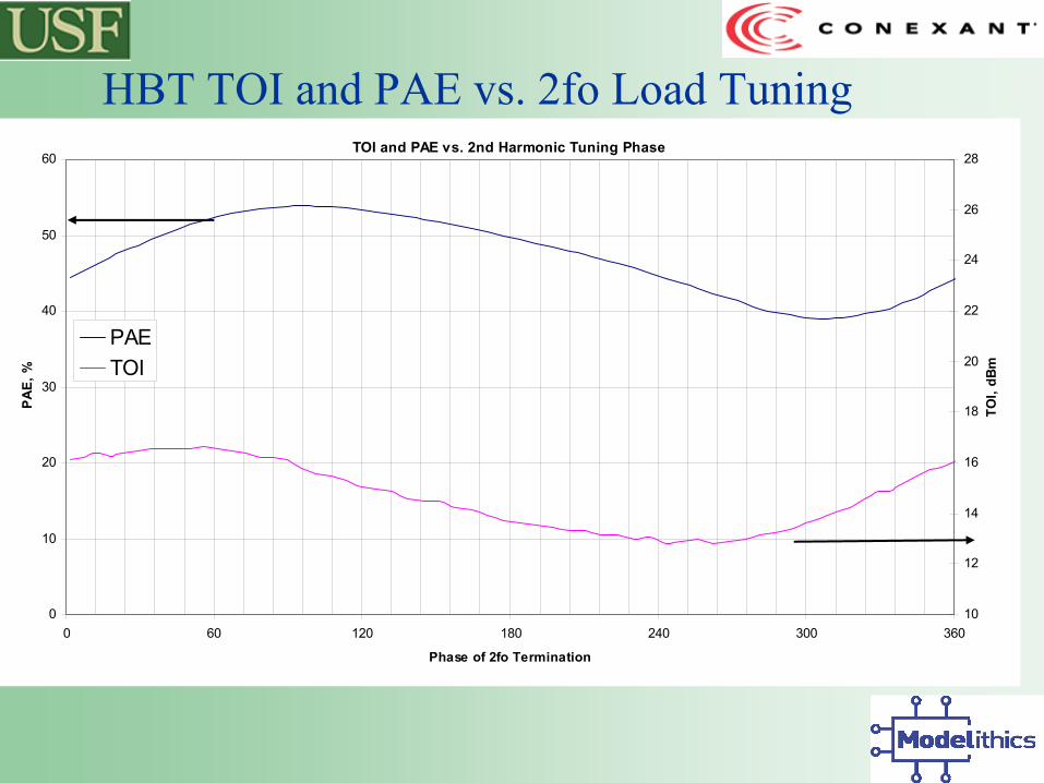
HBT TOI and PAE vs. 2fo Load TuningTOI and PAE vs. 2nd Harmonic Tuning Phase
0
10
20
30
40
50
60
0 60 120 180 240 300 360
Phase of 2fo Termination
PAE,
%
10
12
14
16
18
20
22
24
26
28
TOI,
dBm
PAETOI

HBT Summary
• Accurate S-Parameter model prediction.– Phase within 5°, magnitude within 0.05.
• Power and Gain predicted by <1 dB.• TOI prediction is optimistic at < P1dB.• 2fo tuning makes an impact for Class AB.
– TOI increased 2 dB near open circuit Z.

Conclusions
• Characterization of Maury Harmonic Tuning using Triplexers needs Delta Gt system error validation runs. – Harmonic Delta Gt paths should be setup as
the primary path fundamental, calibrated, and verified using the Delta Gt technique.
• TOI is a function of Harmonic Tuning– Results depend upon device technology.– Improvements are not as dramatic as PAE.

References• Paviol, J., Kueckels, E., Varanasi, R., & Dunleavy, L.D., “PA Load Pull
Error Limits using Delta Gt Contours,” PA Conference, 2003• Spirito, M., de Vreede, L., Nanver, L., Weber, S., Burghartz, J.N., “Power
Amplifier PAE and Ruggedness Optimization by Second Harmonic Control,” IEEE Journal of Solid-State Circuits, Vol. 38, No.9, September 2003, pp. 1575-1583.
• F. van Rijs, R. Dekker, H.A. Visser, H.G. A. Huizing, D. Hartskeerl, P.H.C. Magnee, and R. Dondero, “Influence of output impedance on power added efficiency of Si-bipolar transistors,” in IEEE MTT-S Dig. Tech. Papers, Boston, MA, 2000, pp. 1945-1948.
• R. Mahmoudi, M. Spirito, P. Valk, and J. L. Tauritz, “A novel load and source tuning system for balanced and unbalanced WCDMA power amplifiers,” in 54th ARFTG Conference Digest, Atlanta, GA, Dec. 1999, pp. 1-9.
• Watanabe, S., Takatuka, S., Takagi, K., Kuroda, H., and Oda, Y.,“Simulation and Experimental Results of Source Harmonic Tuning onLinearity of Power GaAs FET under Class AB Operation,” 1996 IEEE-MTT-S Digest, pp. 1771-1774
• Ghannouchi, F.M., Beauregard, F., Kouki, A.B., “Large Signal Stability and Spectrum Characterization of a Medium Power HBT Using ActiveLoad Pull Techniques,” IEEE Microwave and Guided Wave Letters, Volume 4, Number 6, June 1994, pp. 191-193.