using the drawing and color tools -...
TRANSCRIPT

3Using the Drawing andColor Tools
Adobe Flash CS3 Professional has a powerful set of drawing and color
tools to help you create artwork for your animations. In addition to
creating drawings from scratch, you can import existing artwork into Flash
CS3 from other programs such as Adobe Fireworks, Adobe Photoshop,
or Adobe Illustrator. You’ll learn how in Chapter 19, “Integration.”
In this chapter, you’ll learn how to create drawings from scratch in Flash
CS3 using the drawing and color tools. You’ll also learn how to apply
complex gradients to objects, and you’ll learn about the Object Drawing
model, which makes it easier to work with and modify shapes.
Adobe Flash CS3 Professional : H•O•T22
Drawing Tools Defined 22
Lines, Strokes, and Fills Defined 23
Drawing with the Pencil Tool 26
Using the Oval and Rectangle Tools 29
Using the Brush Tool 34
Modifying Lines and Shapes 37
Modifying Strokes and Fills 43
What Is the Color Panel? 43
Understanding the Flash Drawing Models 46
Using the Merge and Object Drawing Models 48
Grouping Objects 52
Creating Gradients 54
Drawing with the Pen Tool 58
Modifying Paths 62
03_FlashCS3HOT_(22-65).qxd 08/08/2007 01:03 PM Page 22

Flash CS3 contains a set of powerful drawingtools. Although many of the tools may be familiarto you from other programs, you’ll find some ofthem are quite unique. The following chart out-lines the behavior of each drawing tool, including
the associated keyboard shortcuts. Don’t feelcompelled to read through everything here. If you want to jump into the exercises, go rightahead. Either way, you’ll be comfortable drawing in Flash CS3 in a very short time!
23Chapter 3 : Using the Drawing and Color Tools
Drawing Tools Defined
Drawing Tools in Flash CS3
Icon Name What Does It Do?
Selection (V) Selects, moves, and edits shapes and drawings.
Subselection (A) Modifies the anchor points and tangent handles of a shape’s pathor outline.
Free Transform (Q) Freely transforms objects, groups, instances, or text blocks. Withthis tool, you can move, rotate, scale, skew, and distort individualtransformations or combine several transformations all at once.
Gradient Modifies the gradient fills of shapes and is stored in the pop-up Transform (F) menu with the Free Transform tool. With the Gradient Transform
tool, you can adjust the size, direction, or center of the fill; pre-cisely control the location of the gradient focal point; and applyother parameters to your gradients.
Lasso (L) Creates irregular-shaped selections of your artwork by drawing afreehand selection around it. Use the Lasso options to fine-tuneand adjust your selections.
Pen (P) Creates straight or curved line segments and is the only drawingtool in Flash CS3 that lets you create Bézier curves, which givesyou precise control of your line segments.
Text (T) Creates static text or text fields. With text fields, you can acceptuser input and even display HTML (HyperText Markup Language)–formatted text that has been loaded from an external text file intoa movie.
Line (N) Draws straight lines. Holding down the Shift key lets you con-strain the lines to 45-degree angles. You can modify the linesdrawn with this tool by using the Ink Bottle tool or by using thecontrols in the Property inspector.
continues on next page
03_FlashCS3HOT_(22-65).qxd 08/08/2007 01:03 PM Page 23
24 Adobe Flash CS3 Professional : H•O•T
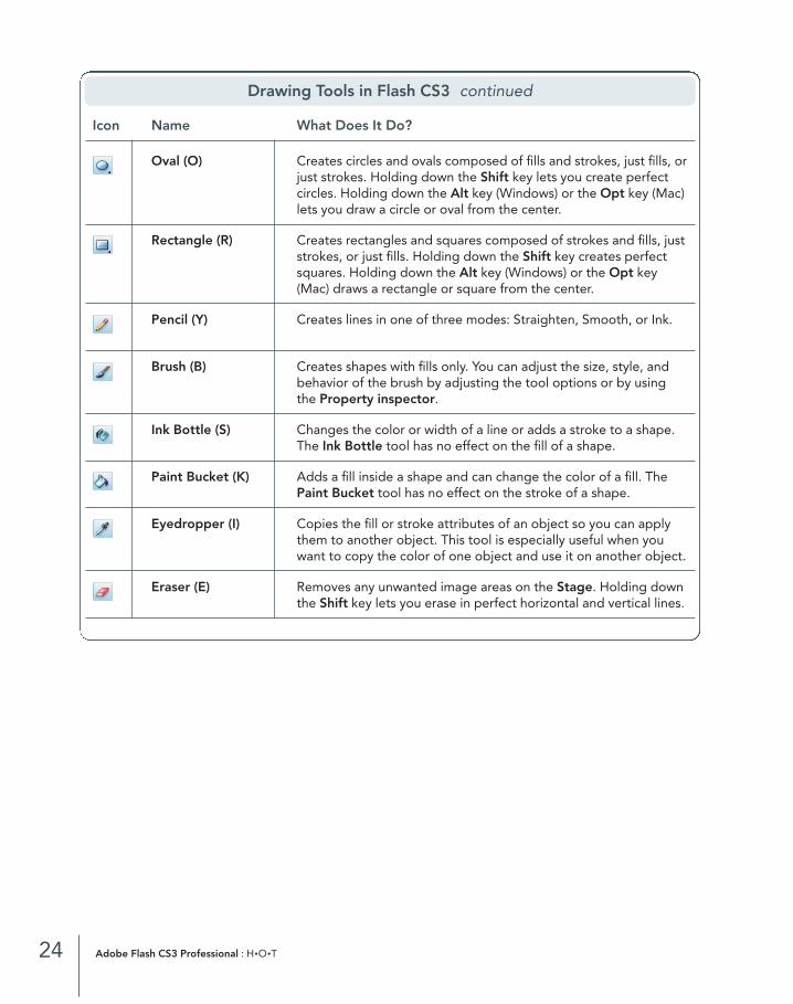
Drawing Tools in Flash CS3 continued
Icon Name What Does It Do?
Oval (O) Creates circles and ovals composed of fills and strokes, just fills, orjust strokes. Holding down the Shift key lets you create perfectcircles. Holding down the Alt key (Windows) or the Opt key (Mac)lets you draw a circle or oval from the center.
Rectangle (R) Creates rectangles and squares composed of strokes and fills, juststrokes, or just fills. Holding down the Shift key creates perfectsquares. Holding down the Alt key (Windows) or the Opt key(Mac) draws a rectangle or square from the center.
Pencil (Y) Creates lines in one of three modes: Straighten, Smooth, or Ink.
Brush (B) Creates shapes with fills only. You can adjust the size, style, andbehavior of the brush by adjusting the tool options or by usingthe Property inspector.
Ink Bottle (S) Changes the color or width of a line or adds a stroke to a shape.The Ink Bottle tool has no effect on the fill of a shape.
Paint Bucket (K) Adds a fill inside a shape and can change the color of a fill. ThePaint Bucket tool has no effect on the stroke of a shape.
Eyedropper (I) Copies the fill or stroke attributes of an object so you can applythem to another object. This tool is especially useful when youwant to copy the color of one object and use it on another object.
Eraser (E) Removes any unwanted image areas on the Stage. Holding downthe Shift key lets you erase in perfect horizontal and vertical lines.
03_FlashCS3HOT_(22-65).qxd 08/08/2007 01:03 PM Page 24

Lines, Strokes, and Fills
Element Example Description
Lines and strokes Create line drawings with the Pencil, Pen, andLine tools. Create strokes or outlines with theRectangle and Oval tools. The terms stroke andfill are used interchangeably in the Flash CS3documentation and throughout this bookbecause you can modify both shapes and strokesusing the same tools. Lines and strokes are inde-pendent of fills, and you can modify them usingthe Ink Bottle tool, the Color and Tool modifiersin the Tools panel, the Color panel, or the StrokeColor in the Property inspector.
Fills Create fills with the Brush and Paint Buckettools. You can create fills without strokes, asshown in the illustration here. You can modify fillsusing the Paint Bucket tool, the Color and Toolmodifiers in the Tools panel, the Color panel, orthe Property inspector.
Strokes, lines, Attach strokes and lines to fills, as shown in the fills, and shapes illustration here, with the Ink Bottle tool. Modify
them using the Ink Bottle tool, the Color and Toolmodifiers in the Tools panel, the Color panel, or the Property inspector. Flash CS3 refers tostrokes, lines, and fills, or a combination thereof,as shapes. Shapes appear as a dotted mesh onthe Stage and display the word shape in theProperty inspector.
25Chapter 3 : Using the Drawing and Color Tools
Lines, Strokes, and Fills DefinedIn addition to learning how each of the drawingtools behave, you need to understand the differ-ence between fills, strokes, lines, and shapes.These differences can be confusing because the
interface refers to both lines and strokes. The following chart provides an example and a briefexplanation of each:
03_FlashCS3HOT_(22-65).qxd 08/08/2007 01:03 PM Page 25

1E X E R C I S E
Drawing with the Pencil Tool
The Pencil tool creates freehand line drawings. By selecting one of the three modes—Straighten, Smooth,or Ink—you can control how the lines are drawn. In this exercise, you will draw a circle with the Pencil toolusing each of the three modes so you can better understand how each one behaves.
Copy the chap_03 folder fromthe Flash HOT CD-ROM to yourdesktop. Open pencil.fla from thechap_03 folder.
As you can see, pencil.fla is ablank file with the Stage dimen-sions set to 400 x 200 pixels,which should be enough space for you to draw some shapes.
Select the Pencil tool in the Tools panel, and choose Straighten from the PencilMode pop-up menu.
As you can see, the Pencil Mode pop-up menu is located in the Options section ofthe Tools panel. The Options section is context-sensitive based on the tool selectedin the Tools panel.
2
1
26 Adobe Flash CS3 Professional : H•O•T
03_FlashCS3HOT_(22-65).qxd 08/08/2007 01:03 PM Page 26

The circles as you draw in Straighten mode The circle when you finish drawing in Straighten mode
Click and drag to draw a circle on the Stage.
Notice when you release the mouse, the shape automatically snaps to a perfect circle. The Straightenmode guesses what shape you are trying to draw and automatically creates a perfect geometric shape.
In the Tools panel, choose Smooth from the Pencil Mode pop-up menu.
The circle as you draw in Smooth mode The circle when you finish drawing in Smooth mode
Click and drag to draw another circle on the Stage.
Notice when your release the mouse, the circle gets smoother, but the change is less significant thanwhen you used Straighten mode.
5
4
3
27Chapter 3 : Using the Drawing and Color Tools
N O T E : About the Pencil Tool ModesIn Flash CS3, the Pencil tool is similar to tools in other graphics programs, such asIllustrator and Photoshop. One of the great features of the Pencil tool in Flash CS3 is the different drawing modes—Straighten, Smooth, and Ink—which give you moreprecise control over your drawings.
As shown in the illustration here, drawing with the Straighten mode creates perfect,geometric shapes; drawing with the Smooth mode smoothes the edges of shapes;and drawing with the Ink mode represents the line exactly as you draw it, giving it the most hand-drawn appearance of the three modes.
Straighten:Perfect look
Smooth:Smooth look
Ink:Hand-drawn look
03_FlashCS3HOT_(22-65).qxd 08/08/2007 01:03 PM Page 27

The circle as you draw in Ink mode The circle when you release the mouse
In the Tools panel, choose Ink from the Pencil Mode pop-up menu. Click and drag to draw a thirdcircle on the Stage.
Notice when using the Ink mode there is very little change in the circle when you release the mouse.
Tired of drawing circles? Go ahead and practice drawing other simple shapes, such as squares, trian-gles, polygons, and so on, with each of the Pencil Mode options. You’ll get an even better idea of howeach drawing mode works and how each one can help you create artwork in Flash CS3.
Tip: To clear the Stage, press Ctrl+A (Windows) or Cmd+A (Mac) to select everything on the Stage, andthen press the Delete key.
When you are done experimenting with the Pencil tool, close pencil.fla. You don’t need to save your changes.8
7
6
28 Adobe Flash CS3 Professional : H•O•T
03_FlashCS3HOT_(22-65).qxd 08/08/2007 01:03 PM Page 28

2E X E R C I S E
Using the Oval and Rectangle Tools
The Oval and Rectangle tools are ideal for creating geometric shapes, such as ovals, circles, rectangles,and squares. You can create simple shapes with independent lines and fills quickly and effortlessly. In thisexercise, you’ll learn how to use these tools.
Open shapes.fla from the chap_03 folder.
The shapes.fla file is a blank file you can use to draw shapes.
Select the Oval tool from the Rectangle tool pop-up menu in the Tools panel. At the bottom of the Toolspanel are two options: Object Drawing, which lets youchoose which drawing model to use (you will learn aboutdrawing models later in this chapter), and Snap toObjects, which makes it easier to align objects on theStage. Click the Snap to Objects button.
Notice how the Property inspector has updated to showoptions for drawing an oval. New in Flash CS3, you cancontrol the inner and outer radii of ovals you create withthe Oval tool. You must set these options before youdraw an oval, unless you use the Oval Primitive tool.(You’ll learn about the Oval Primitive tool in Step 5.)
In this exercise, you’ll learn how to create shapes usingthe Merge Drawing model (the default drawing model)and the Snap to Objects feature. Later in this chapter, you’ll create shapes using the Object Drawing model.
Hold down the Shift key, and click and drag to draw a circle on the Stage.
Holding down the Shift key while drawing creates a perfect circle. Notice Flash CS3 automatically uses the current fill and stroke colors to create the circle.
Click and drag to create an oval on the Stage.
When you don’t hold down the Shift key while drawing, FlashCS3 doesn’t constrain the shape as a perfect circle. Also, thedrawing cursor is different from how it appeared in Step 3. The cursor change is a visual clue you are drawing an oval or a circle.
4
3
2
1
29Chapter 3 : Using the Drawing and Color Tools
Object Drawing
Snap to Objects
03_FlashCS3HOT_(22-65).qxd 08/08/2007 01:03 PM Page 29

Select the Oval Primitive tool from the Oval tool pop-up menu in theTools panel.
The Oval Primitive tool differs from the Oval tool in that it allows you tomodify an oval’s radii before or after the oval is created.
In the Property inspector, set the End Angle property to 60.
Adjusting the Start Angle or End Angle setting will give you a pie shape. Adjusting the Inner Radius setting will result in a doughnut shape.
Click and drag to create a pie shape on the Stage.
Click anywhere on the Stage to deselect the pie shape. In the Property inspector, change EndAngle to 0, change Inner Radius to 30, and click and drag to create a doughnut shape on the Stage.
Notice the circular handles on the shape you just created. You can also click and drag these handles with the Selection tool to adjust the radii of your shape.
8
7
6
5
30 Adobe Flash CS3 Professional : H•O•T
03_FlashCS3HOT_(22-65).qxd 08/08/2007 01:03 PM Page 30
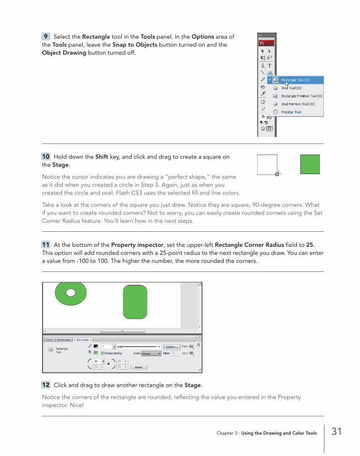
Select the Rectangle tool in the Tools panel. In the Options area of the Tools panel, leave the Snap to Objects button turned on and theObject Drawing button turned off.
Hold down the Shift key, and click and drag to create a square on the Stage.
Notice the cursor indicates you are drawing a “perfect shape,” the same as it did when you created a circle in Step 3. Again, just as when you created the circle and oval, Flash CS3 uses the selected fill and line colors.
Take a look at the corners of the square you just drew. Notice they are square, 90-degree corners. Whatif you want to create rounded corners? Not to worry, you can easily create rounded corners using the SetCorner Radius feature. You’ll learn how in the next steps.
At the bottom of the Property inspector, set the upper-left Rectangle Corner Radius field to 25.This option will add rounded corners with a 25-point radius to the next rectangle you draw. You can entera value from -100 to 100. The higher the number, the more rounded the corners.
Click and drag to draw another rectangle on the Stage.
Notice the corners of the rectangle are rounded, reflecting the value you entered in the Property inspector. Nice!
12
11
10
9
31Chapter 3 : Using the Drawing and Color Tools
03_FlashCS3HOT_(22-65).qxd 08/08/2007 01:03 PM Page 31
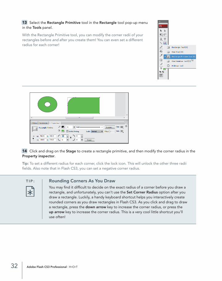
Select the Rectangle Primitive tool in the Rectangle tool pop-up menuin the Tools panel.
With the Rectangle Primitive tool, you can modify the corner radii of yourrectangles before and after you create them! You can even set a differentradius for each corner!
Click and drag on the Stage to create a rectangle primitive, and then modify the corner radius in theProperty inspector.
Tip: To set a different radius for each corner, click the lock icon. This will unlock the other three radiifields. Also note that in Flash CS3, you can set a negative corner radius.
14
13
32 Adobe Flash CS3 Professional : H•O•T
T I P : Rounding Corners As You DrawYou may find it difficult to decide on the exact radius of a corner before you draw arectangle, and unfortunately, you can’t use the Set Corner Radius option after youdraw a rectangle. Luckily, a handy keyboard shortcut helps you interactively createrounded corners as you draw rectangles in Flash CS3. As you click and drag to draw a rectangle, press the down arrow key to increase the corner radius, or press the up arrow key to increase the corner radius. This is a very cool little shortcut you’ll use often!
03_FlashCS3HOT_(22-65).qxd 08/08/2007 01:03 PM Page 32

Save your shapes.fla file by choosing File > Save. Close the file.15
33Chapter 3 : Using the Drawing and Color Tools
N O T E : Oval and Rectangle SettingsIf you want to create a specific-sized oval or rec-tangle, you may find it difficult to do so with theOval tool or Rectangle tool. Fortunately, youcan also specify the width and height of ovalsand rectangles, as well as the corner radii of rectangles, by using the controls in the OvalSettings and Rectangle Settings dialog boxes.
With either the Oval tool or the Rectangle tool selected in the Tools panel, Alt-click(Windows) or Opt-click (Mac) an empty area on the Stage where you want to createthe oval or rectangle. In the Oval Settings or Rectangle Settings dialog box, specifyyour settings, and click OK. Flash CS3 automatically draws an appropriate-sized ovalor rectangle where you clicked.
03_FlashCS3HOT_(22-65).qxd 08/08/2007 01:03 PM Page 33

3E X E R C I S E
Using the Brush Tool
You can use the Brush tool to paint shapes with solid colors, gradients, and even bitmap fills. In this exer-cise, you’ll learn how to use the Brush tool to create and modify shapes.
Open paint.fla from the chap_03 folder.
The paint.fla file is a blank file you can use to draw shapes.
Select the Brush tool in the Tools panel.
Notice the Brush tool has several options—Object Drawing,Lock Fill, Brush Mode, Brush Size, and Brush Shape. You’ll learn about these options in this exercise.
Draw a circle on the Stage.
Notice Flash CS3 uses the fill color for this shape, not thestroke color. The Brush tool creates shapes that are fills and,therefore, uses only the fill color.
3
2
1
34 Adobe Flash CS3 Professional : H•O•T
Lock Fill
Brush Shape
Object Drawing
Brush Mode
Brush Size
03_FlashCS3HOT_(22-65).qxd 08/08/2007 01:03 PM Page 34
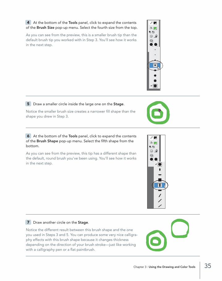
At the bottom of the Tools panel, click to expand the contentsof the Brush Size pop-up menu. Select the fourth size from the top.
As you can see from the preview, this is a smaller brush tip than thedefault brush tip you worked with in Step 3. You’ll see how it worksin the next step.
Draw a smaller circle inside the large one on the Stage.
Notice the smaller brush size creates a narrower fill shape than theshape you drew in Step 3.
At the bottom of the Tools panel, click to expand the contentsof the Brush Shape pop-up menu. Select the fifth shape from thebottom.
As you can see from the preview, this tip has a different shape thanthe default, round brush you’ve been using. You’ll see how it worksin the next step.
Draw another circle on the Stage.
Notice the different result between this brush shape and the oneyou used in Steps 3 and 5. You can produce some very nice calligra-phy effects with this brush shape because it changes thicknessdepending on the direction of your brush stroke—just like workingwith a calligraphy pen or a flat paintbrush.
7
6
5
4
35Chapter 3 : Using the Drawing and Color Tools
03_FlashCS3HOT_(22-65).qxd 08/08/2007 01:03 PM Page 35
Experiment with the other brush shapes and sizes so you are more comfortable with the Brush tool.If you have a graphics tablet, try the pressure sensitivity with the Brush tool.
Note: The Brush tool sizes are relative to the magnification of your Stage. To experiment, zoom in to 400 percent and draw a line; then zoom out to 100 percent and draw another line without modifying the size of your brush.
8
36 Adobe Flash CS3 Professional : H•O•T
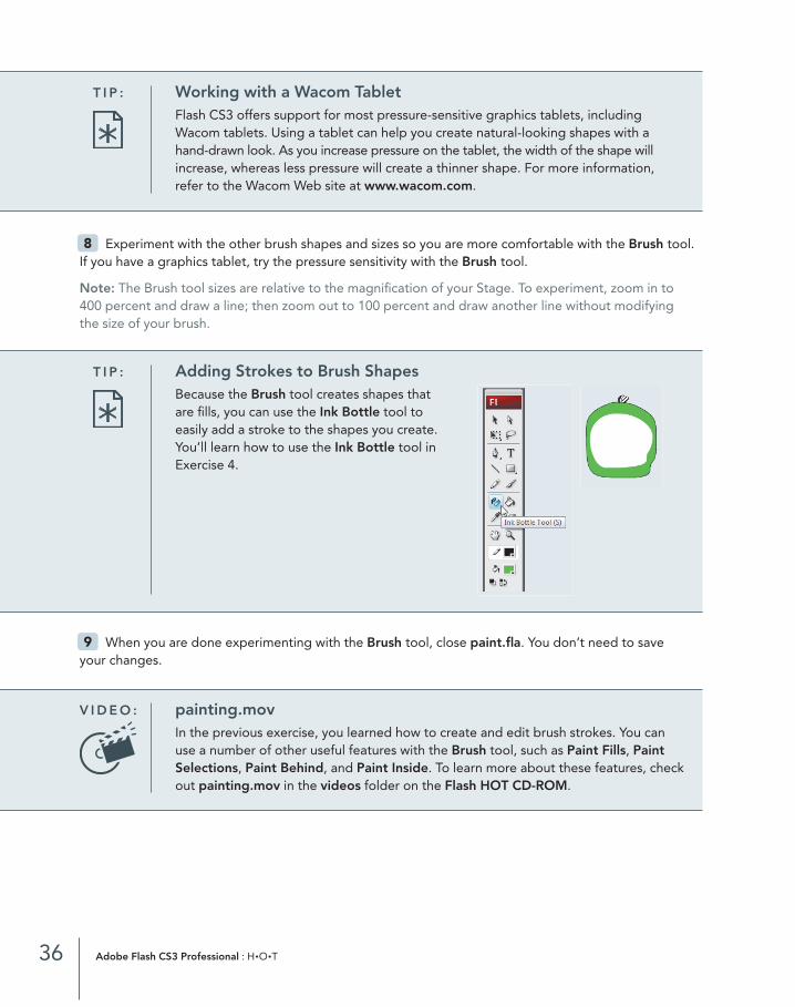
T I P : Working with a Wacom TabletFlash CS3 offers support for most pressure-sensitive graphics tablets, includingWacom tablets. Using a tablet can help you create natural-looking shapes with ahand-drawn look. As you increase pressure on the tablet, the width of the shape willincrease, whereas less pressure will create a thinner shape. For more information,refer to the Wacom Web site at www.wacom.com.
T I P : Adding Strokes to Brush ShapesBecause the Brush tool creates shapes thatare fills, you can use the Ink Bottle tool to easily add a stroke to the shapes you create.You’ll learn how to use the Ink Bottle tool inExercise 4.
When you are done experimenting with the Brush tool, close paint.fla. You don’t need to save your changes.9
V I D E O : painting.movIn the previous exercise, you learned how to create and edit brush strokes. You canuse a number of other useful features with the Brush tool, such as Paint Fills, PaintSelections, Paint Behind, and Paint Inside. To learn more about these features, checkout painting.mov in the videos folder on the Flash HOT CD-ROM.
03_FlashCS3HOT_(22-65).qxd 08/08/2007 01:03 PM Page 36

4E X E R C I S E
Modifying Lines and Shapes
In the previous three exercises, you learned how to draw lines and create shapes with the Brush, Oval,and Rectangle tools. You’ll learn how to modify these shapes in this exercise and the next one. In this exercise, you’ll learn how to use the Property inspector and Ink Bottle to modify the appearance ofexisting lines. In addition, you will learn some of the nuances involved in selecting lines and when to use the Ink Bottle tool versus the Property inspector.
Open strokes.fla from the chap_03 folder.
This file contains shapes created with lines and fills, whichyou’ll use to modify lines and add strokes to shapes.
Select the Selection tool in the Tools panel, and click thesquiggle drawing to select it.
Notice when you select the line, it gets a bit thicker, and adotted mesh appears over it, indicating the line is selected.
Make sure the Property inspector is visible. If it’s not, choose Window > Properties > Properties.
Note: You must select a line before you can modify its stroke settings using the Property inspector.
3
2
1
37Chapter 3 : Using the Drawing and Color Tools
Stroke HeightShape Dimensions
Stroke Color Stroke StyleFill Color Custom Stroke Style
03_FlashCS3HOT_(22-65).qxd 08/08/2007 01:03 PM Page 37
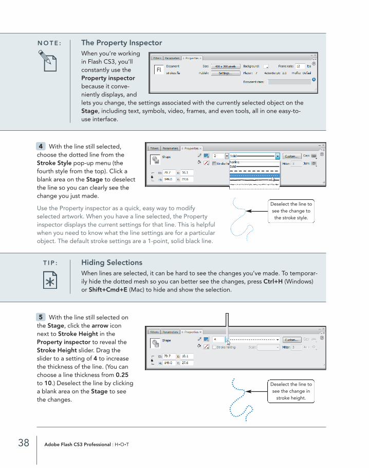
With the line still selected onthe Stage, click the arrow iconnext to Stroke Height in theProperty inspector to reveal theStroke Height slider. Drag theslider to a setting of 4 to increasethe thickness of the line. (You canchoose a line thickness from 0.25to 10.) Deselect the line by clicking a blank area on the Stage to see the changes.
5
With the line still selected,choose the dotted line from theStroke Style pop-up menu (thefourth style from the top). Click ablank area on the Stage to deselectthe line so you can clearly see thechange you just made.
Use the Property inspector as a quick, easy way to modifyselected artwork. When you have a line selected, the Propertyinspector displays the current settings for that line. This is helpfulwhen you need to know what the line settings are for a particular object. The default stroke settings are a 1-point, solid black line.
4
38 Adobe Flash CS3 Professional : H•O•T
N O T E : The Property InspectorWhen you’re workingin Flash CS3, you’llconstantly use theProperty inspectorbecause it conve-niently displays, andlets you change, the settings associated with the currently selected object on theStage, including text, symbols, video, frames, and even tools, all in one easy-to-use interface.
Deselect the line tosee the change tothe stroke style.
T I P : Hiding SelectionsWhen lines are selected, it can be hard to see the changes you’ve made. To temporar-ily hide the dotted mesh so you can better see the changes, press Ctrl+H (Windows)or Shift+Cmd+E (Mac) to hide and show the selection.
Deselect the line tosee the change in
stroke height.
03_FlashCS3HOT_(22-65).qxd 08/08/2007 01:03 PM Page 38
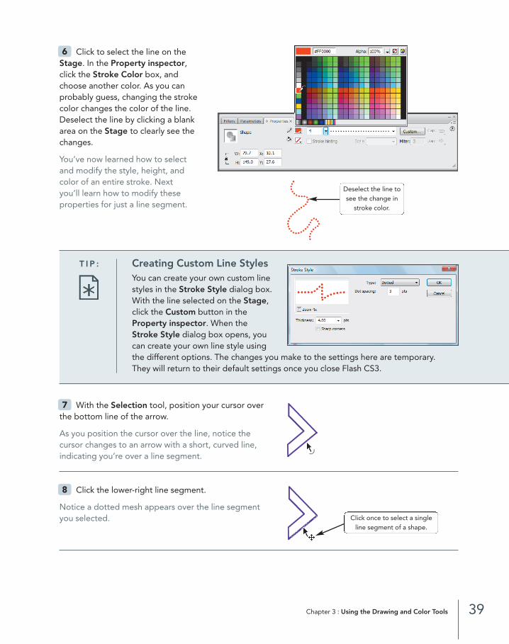
Click to select the line on the Stage. In the Property inspector, click the Stroke Color box, and choose another color. As you can probably guess, changing the stroke color changes the color of the line.Deselect the line by clicking a blankarea on the Stage to clearly see thechanges.
You’ve now learned how to select and modify the style, height, and color of an entire stroke. Next you’ll learn how to modify these properties for just a line segment.
6
39Chapter 3 : Using the Drawing and Color Tools
Deselect the line tosee the change in
stroke color.
T I P : Creating Custom Line StylesYou can create your own custom linestyles in the Stroke Style dialog box.With the line selected on the Stage,click the Custom button in theProperty inspector. When theStroke Style dialog box opens, youcan create your own line style usingthe different options. The changes you make to the settings here are temporary. They will return to their default settings once you close Flash CS3.
With the Selection tool, position your cursor overthe bottom line of the arrow.
As you position the cursor over the line, notice the cursor changes to an arrow with a short, curved line,indicating you’re over a line segment.
Click the lower-right line segment.
Notice a dotted mesh appears over the line segmentyou selected.
8
7
Click once to select a singleline segment of a shape.
03_FlashCS3HOT_(22-65).qxd 08/08/2007 01:03 PM Page 39

In the Property inspector, usethe Stroke Height slider tochange the line width to 5.
Notice only the selected line seg-ment changed. To modify a linesegment, you must select it beforeyou change the settings in theProperty inspector. In this case,you selected only one of the sixline segments of the arrow shape.
9
40 Adobe Flash CS3 Professional : H•O•T
T I P : Selecting Line SegmentsUnlike other drawing programs, Flash CS3 breaks lines with hard angles into separateline segments. For example, clicking the bottom line of the arrow shape selects onlythe bottom portion of the shape because the shape has six hard angles, creating six separate lines. If you want to select the entire shape, double-click only one of theline segments.
With the line segment still selected, type 2.75 in the Stroke Height field in the Property inspector.
If you know the exact value you want to use, you can change the width of a line by typing a specificnumeric value in the field next to the Stroke Height slider.
Click anywhere on the Stage to deselect the line segment. Double-click any part of the arrow to select all six line segments.
This shortcut is essential when you need to select entire shapes composed of multisegmented lines.
Practice changing the style, width, and color of the selected lines using the controls in the Propertyinspector. Choose any setting you like—the point here is to become more comfortable with selectinglines and line segments and changing their properties with the Property inspector.
Now you know how to modify an existing line using the Property inspector, but what do you do whenyour object doesn’t have a line or a stroke? You add one using the Ink Bottle tool. You’ll learn how in thefollowing steps.
12
11
10
The dotted meshindicates the shape
is selected.
03_FlashCS3HOT_(22-65).qxd 08/08/2007 01:03 PM Page 40
Select the Ink Bottle tool in the Tools panel.
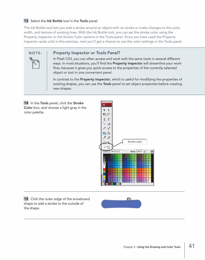
The Ink Bottle tool lets you add a stroke around an object with no stroke or make changes to the color,width, and texture of existing lines. With the Ink Bottle tool, you can set the stroke color using theProperty inspector or the Stroke Color options in the Tools panel. Since you have used the Propertyinspector quite a bit in this exercise, next you’ll get a chance to use the color settings in the Tools panel.
13
41Chapter 3 : Using the Drawing and Color Tools
N O T E : Property Inspector or Tools Panel?In Flash CS3, you can often access and work with the same tools in several differentways. In most situations, you’ll find the Property inspector will streamline your work-flow, because it gives you quick access to the properties of the currently selectedobject or tool in one convenient panel.
In contrast to the Property inspector, which is useful for modifying the properties ofexisting shapes, you can use the Tools panel to set object properties before creatingnew shapes.
In the Tools panel, click the Stroke Color box, and choose a light gray in thecolor palette.
Click the outer edge of the snowboardshape to add a stroke to the outside of the shape.
15
14
Stroke color
03_FlashCS3HOT_(22-65).qxd 08/08/2007 01:03 PM Page 41
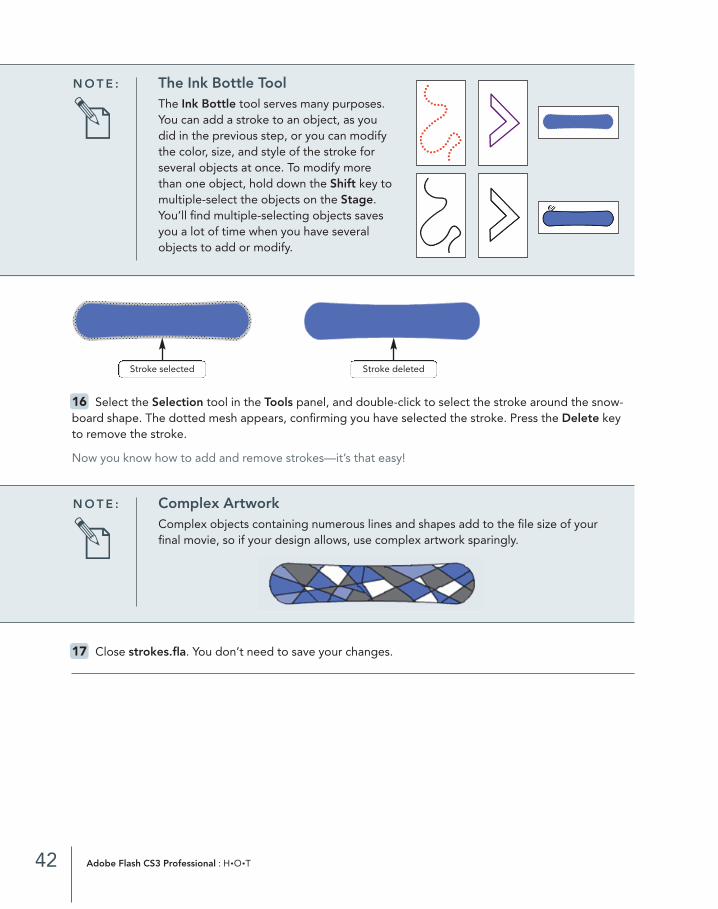
Select the Selection tool in the Tools panel, and double-click to select the stroke around the snow-board shape. The dotted mesh appears, confirming you have selected the stroke. Press the Delete keyto remove the stroke.
Now you know how to add and remove strokes—it’s that easy!
16
42 Adobe Flash CS3 Professional : H•O•T
N O T E : The Ink Bottle ToolThe Ink Bottle tool serves many purposes.You can add a stroke to an object, as youdid in the previous step, or you can modifythe color, size, and style of the stroke forseveral objects at once. To modify morethan one object, hold down the Shift key tomultiple-select the objects on the Stage.You’ll find multiple-selecting objects savesyou a lot of time when you have severalobjects to add or modify.
Stroke selected Stroke deleted
N O T E : Complex ArtworkComplex objects containing numerous lines and shapes add to the file size of yourfinal movie, so if your design allows, use complex artwork sparingly.
Close strokes.fla. You don’t need to save your changes.17
03_FlashCS3HOT_(22-65).qxd 08/08/2007 01:03 PM Page 42
5E X E R C I S E
Modifying Strokes and Fills
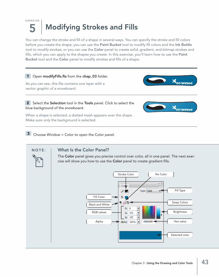
You can change the stroke and fill of a shape in several ways. You can specify the stroke and fill colorsbefore you create the shape; you can use the Paint Bucket tool to modify fill colors and the Ink Bottletool to modify strokes; or you can use the Color panel to create solid, gradient, and bitmap strokes andfills, which you can apply to the shapes you create. In this exercise, you’ll learn how to use the PaintBucket tool and the Color panel to modify strokes and fills of a shape.
Open modifyFills.fla from the chap_03 folder.
As you can see, this file contains one layer with a vector graphic of a snowboard.
Select the Selection tool in the Tools panel. Click to select theblue background of the snowboard.
When a shape is selected, a dotted mesh appears over the shape. Make sure only the background is selected.
Choose Window > Color to open the Color panel.3
2
1
43Chapter 3 : Using the Drawing and Color Tools
N O T E : What Is the Color Panel?The Color panel gives you precise control over color, all in one panel. The next exer-cise will show you how to use the Color panel to create gradient fills.
BrightnessRGB values
Alpha
Fill Color
Black and White
Selected color
Hex value
Swap Colors
No ColorStroke Color
Fill Type
03_FlashCS3HOT_(22-65).qxd 08/08/2007 01:03 PM Page 43
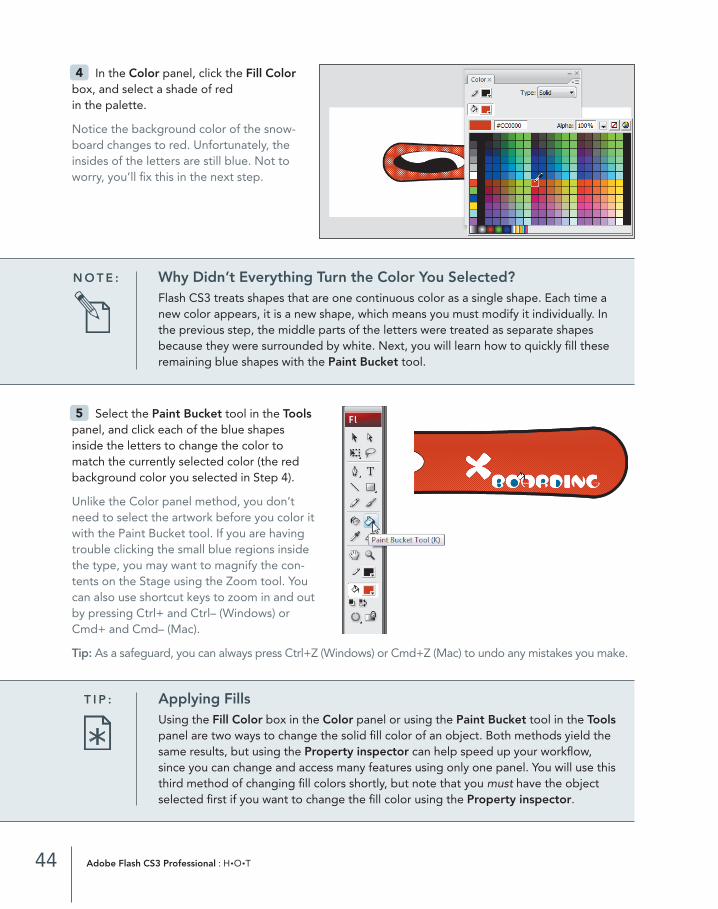
In the Color panel, click the Fill Colorbox, and select a shade of red in the palette.
Notice the background color of the snow-board changes to red. Unfortunately, theinsides of the letters are still blue. Not toworry, you’ll fix this in the next step.
4
44 Adobe Flash CS3 Professional : H•O•T
N O T E : Why Didn’t Everything Turn the Color You Selected?Flash CS3 treats shapes that are one continuous color as a single shape. Each time anew color appears, it is a new shape, which means you must modify it individually. Inthe previous step, the middle parts of the letters were treated as separate shapesbecause they were surrounded by white. Next, you will learn how to quickly fill theseremaining blue shapes with the Paint Bucket tool.
Select the Paint Bucket tool in the Toolspanel, and click each of the blue shapesinside the letters to change the color tomatch the currently selected color (the redbackground color you selected in Step 4).
Unlike the Color panel method, you don’tneed to select the artwork before you color itwith the Paint Bucket tool. If you are havingtrouble clicking the small blue regions insidethe type, you may want to magnify the con-tents on the Stage using the Zoom tool. Youcan also use shortcut keys to zoom in and outby pressing Ctrl+ and Ctrl– (Windows) or Cmd+ and Cmd– (Mac).
Tip: As a safeguard, you can always press Ctrl+Z (Windows) or Cmd+Z (Mac) to undo any mistakes you make.
5
T I P : Applying FillsUsing the Fill Color box in the Color panel or using the Paint Bucket tool in the Toolspanel are two ways to change the solid fill color of an object. Both methods yield thesame results, but using the Property inspector can help speed up your workflow,since you can change and access many features using only one panel. You will use thisthird method of changing fill colors shortly, but note that you must have the objectselected first if you want to change the fill color using the Property inspector.
03_FlashCS3HOT_(22-65).qxd 08/08/2007 01:03 PM Page 44

Select the Selection tool in the Tools panel. Click the letter Bon the snowboard to select it. You’ll know it’s selected when yousee the dotted mesh.
You could select and change the color of each letter individually,but that would be a time-consuming process. Instead, you’ll usethe Shift key to multiple-select all the letters in the word BOARDING so you can fill all the letters at the same time.
Hold down the Shift key, and click each of the remaining letters in the word BOARDING to multiple-select all the letters. If you make a mistake and want to start over, press the Esc key to clear all selections,or click a blank area on the Stage to deselect.
Make sure the Property inspector isvisible. If it’s not, choose Window >Properties > Properties. In theProperty inspector, click the Fill Colorbox, and select black in the Fill Colorpalette.
Notice all the letters changed to the new color you selected! Nowthat you’ve mastered changing fills, it’s time to learn how to mod-ify strokes. You’ll learn how in the next few steps.
With the Selection tool still selected in the Toolspanel, double-click the snowboard to select it.
Double-clicking will select the entire object, including both strokes—the one around the snowboard and also the one around the yin and yang design.
Tip: To select a single stroke, double-click the stroke.
In the Property inspector, click theStroke Color box, and select a shade ofyellow in the Stroke Color palette.Choose a different stroke style from theStroke Style pop-up menu. When you’re finished, click a blank area on the Stage to deselect your artwork so you can see your changes clearly.
10
9
8
7
6
45Chapter 3 : Using the Drawing and Color Tools
03_FlashCS3HOT_(22-65).qxd 08/08/2007 01:03 PM Page 45

Double-click the stroke of the yin and yang design on the snowboard to select it. In the Property inspector, select a new Stroke Color and Stroke Height for the outline. When you’re finished, click a blank area on the Stage to deselect your artwork so you can see your changes clearly.
Close modifyFills.fla. You don’t need to save your changes.12
11
46 Adobe Flash CS3 Professional : H•O•T
Now that you’ve mastered how to use the draw-ing tools in Flash CS3, it’s time to learn about thetwo drawing models in Flash CS3: the MergeDrawing model and the Object Drawing model.The drawing models define how multiple shapesinteract with each other, particularly when youcreate overlapping shapes.
The Merge Drawing model, which has been thedefault drawing model in previous versions ofFlash, automatically merges overlapping shapes.As a result, if you create overlapping shapes andthen move the shapes away from the each other,you end up with broken or merged shapes. For
many users, the Merge Drawing model was diffi-cult to understand because it was so differentfrom models in other drawing programs.
Fortunately, Flash CS3 has another drawingmodel—the Object Drawing model—that providesmore control and flexibility when creating multipleor overlapping objects. The Object Drawingmodel behaves the way models in other drawingprograms behave. Before you get started with thehands-on exercises, take some time to review thefollowing chart, which will help you understandthe differences and benefits of each of the twodrawing models:
Understanding the Flash Drawing Models
03_FlashCS3HOT_(22-65).qxd 08/08/2007 01:03 PM Page 46
47Chapter 3 : Using the Drawing and Color Tools
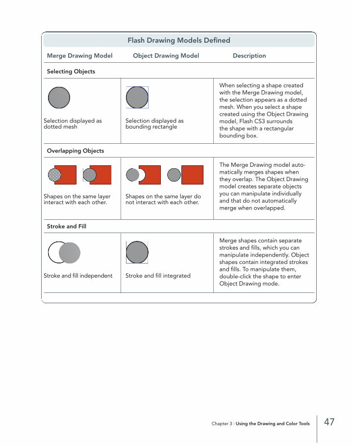
Flash Drawing Models Defined
Merge Drawing Model Object Drawing Model Description
Selecting Objects
Selection displayed as Selection displayed asdotted mesh bounding rectangle
Overlapping Objects
Shapes on the same layer Shapes on the same layer dointeract with each other. not interact with each other.
Stroke and Fill
Stroke and fill independent Stroke and fill integrated
When selecting a shape createdwith the Merge Drawing model,the selection appears as a dottedmesh. When you select a shapecreated using the Object Drawingmodel, Flash CS3 surrounds the shape with a rectangularbounding box.
The Merge Drawing model auto-matically merges shapes whenthey overlap. The Object Drawingmodel creates separate objectsyou can manipulate individuallyand that do not automaticallymerge when overlapped.
Merge shapes contain separatestrokes and fills, which you canmanipulate independently. Objectshapes contain integrated strokesand fills. To manipulate them, double-click the shape to enterObject Drawing mode.
03_FlashCS3HOT_(22-65).qxd 08/08/2007 01:03 PM Page 47

6E X E R C I S E Using the Merge and Object Drawing
ModelsIn this exercise, you will create shapes with each drawing model using the Oval tool to learn the differ-ences, benefits, and nuances of working with each.
Open a new file in Flash CS3 by choosing File >New > Flash File (ActionScript 3.0). Choose a lightgray color in the Fill Color palette and black in theStoke Color palette in the Tools panel. Make sureObject Drawing is deselected. Draw two circles orovals on the Stage.
Select the Selection tool in the Tools panel.Double-click one of the oval shapes on the Stageto select it. Drag to reposition the oval so it overlapsthe other oval.
The Merge Drawing model is the default drawing model. When selected, the merge object displays adotted mesh.
Deselect the oval by clicking the Stage anywhere.Double-click the oval to select it again, and click anddrag it away from the circle.
Notice the selected oval left a hole in the other oval where the two shapes overlapped. When you over-lap objects using the Merge Drawing model, they automatically merge to create a single shape. Whenyou move the shapes apart, the shapes do not return to their original, unmerged states. If you want tokeep the objects as separate, unmerged objects when overlapped, you must use the other drawingmodel in Flash CS3—the Object Drawing model. You will do this next.
3
2
1
48 Adobe Flash CS3 Professional : H•O•T
The dotted mesh indicatesthe selected merge object.
03_FlashCS3HOT_(22-65).qxd 08/08/2007 01:03 PM Page 48

Deselect the oval by clicking anywhere on theStage. Choose a green color in the Fill Colorpalette. Select the Oval tool in the Tools panel. Atthe bottom of the Tools panel, click the ObjectDrawing button to switch from the default MergeDrawing model to the Object Drawing model.
Drag with the Oval tool to create a third oval,adjacent to the first two, on the Stage.
You’ve just created an object shape. Object shapes behave a bit differently than the merge shapes youhave worked with up to this point.
Select the Selection tool in the Tools panel.Click the green oval to select it. Move it so it over-laps one of the gray merge object ovals.
Notice the green oval shape, which was created using the Object Drawing model, is surrounded by a rectangular bounding box, rather than the dotted mesh you saw for the gray merge object ovals.
Click and drag the green oval away from thegray oval. Deselect the green oval by clicking any-where on the Stage.
Unlike in Step 3, the objects did not merge where they overlapped. When you create shapes with theObject Drawing model, they behave independently from other shapes.
Double-click the green oval.
The other gray ovals on the Stage dim, and you can-not select them! Notice the edit bar indicates youare no longer on Scene 1 but are on somethingcalled a drawing object.
8
7
6
5
4
49Chapter 3 : Using the Drawing and Color Tools
The bounding boxindicates a selected
object shape.
03_FlashCS3HOT_(22-65).qxd 08/08/2007 01:03 PM Page 49

Click the green oval, and move it aroundthe Stage.
A dotted mesh replaces the bounding rectan-gle, and the stroke is left behind. The shape no longer looks or behaves as an object shape but as a merge shape! When you double-click an object shape, you automatically exit the Object Drawing model and enter the Merge Drawing model.As a result, object shapes are automatically converted to merge shapes, which in some circumstances areeasier to use. However, this isn’t a permanent change—you can return merge shapes to object shapeseasily. You’ll learn how in the next step.
In the edit bar, click the Scene 1 button to return to the Object Drawing model. The shape no longerbehaves as a merge shape but as an object shape. See for yourself by manipulating the graphics on theStage again.
You now have a good overview of the differencesbetween the two drawing models in Flash CS3. If you’renew to Flash, you may think the Object Drawing modelis the best way to create your Flash artwork, because it behaves like the models in most other graphics programs and because usually you won’t want objects merging witheach other. However, you can achieve some interesting effects using the Merge Drawing model, which you’ll learn about in the following tip.
Close your Flash file. You don’t need to save your changes.11
10
9
50 Adobe Flash CS3 Professional : H•O•T
Stroke
03_FlashCS3HOT_(22-65).qxd 08/08/2007 01:03 PM Page 50
Other than starting out with Object Drawing model shapes, you can overlap shapes in additional wayswithout having them cut into or combine them with one another. You can convert the shapes to symbols,which you will learn more about in Chapter 6, “Creating Symbols and Instances.” You can also select mul-tiple shapes and group them (Modify > Group), which you will learn about in the next exercise. Groupingshapes also makes it easier to work with shapes you want to keep together or modify in the same way.
51Chapter 3 : Using the Drawing and Color Tools
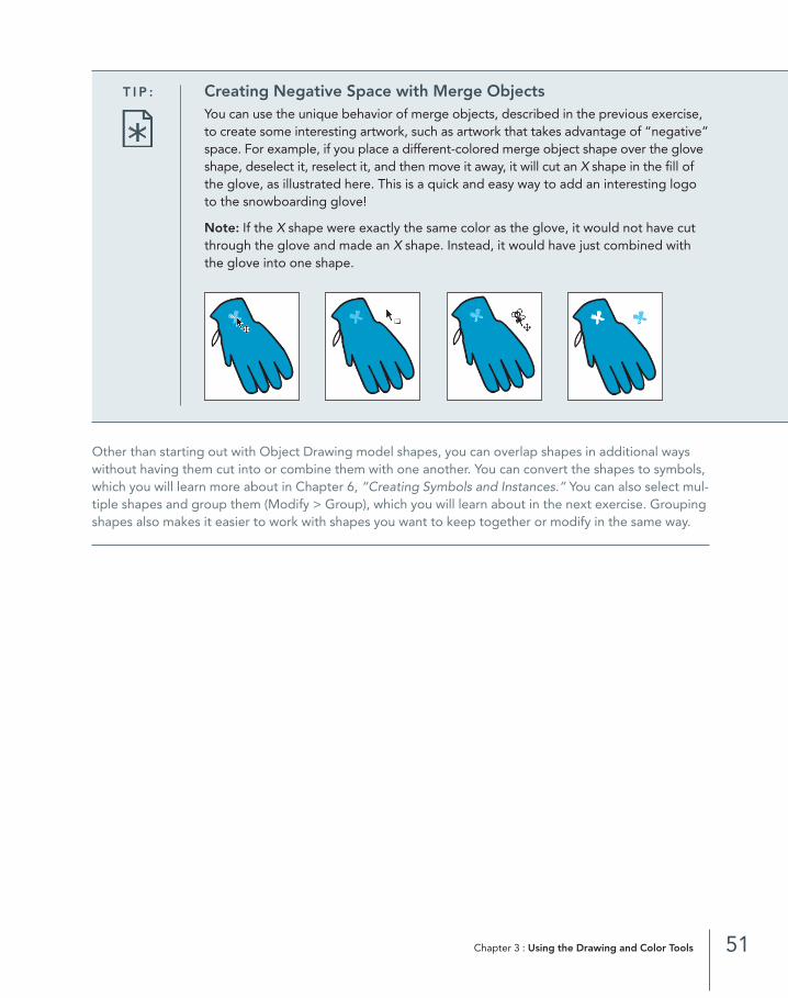
T I P : Creating Negative Space with Merge ObjectsYou can use the unique behavior of merge objects, described in the previous exercise,to create some interesting artwork, such as artwork that takes advantage of “negative”space. For example, if you place a different-colored merge object shape over the gloveshape, deselect it, reselect it, and then move it away, it will cut an X shape in the fill ofthe glove, as illustrated here. This is a quick and easy way to add an interesting logoto the snowboarding glove!
Note: If the X shape were exactly the same color as the glove, it would not have cutthrough the glove and made an X shape. Instead, it would have just combined withthe glove into one shape.
03_FlashCS3HOT_(22-65).qxd 08/08/2007 01:03 PM Page 51
7E X E R C I S E
Grouping Objects
Now that you have a good idea of how the drawing features behave in Flash CS3, this exercise showsyou how to group objects so you can modify and work with them all together.
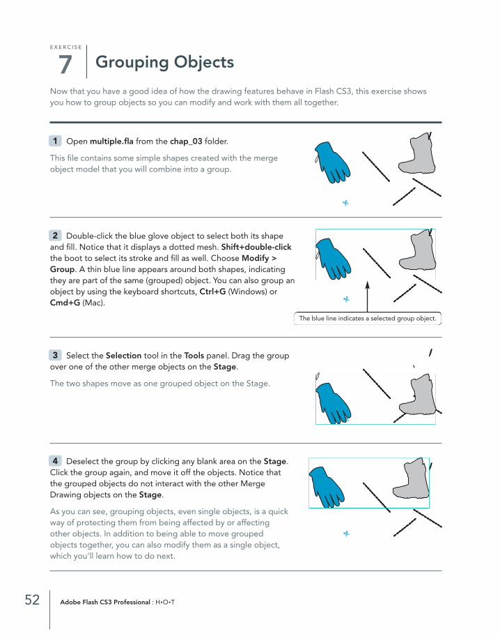
Open multiple.fla from the chap_03 folder.
This file contains some simple shapes created with the mergeobject model that you will combine into a group.
Double-click the blue glove object to select both its shapeand fill. Notice that it displays a dotted mesh. Shift+double-clickthe boot to select its stroke and fill as well. Choose Modify >Group. A thin blue line appears around both shapes, indicatingthey are part of the same (grouped) object. You can also group anobject by using the keyboard shortcuts, Ctrl+G (Windows) orCmd+G (Mac).
Select the Selection tool in the Tools panel. Drag the groupover one of the other merge objects on the Stage.
The two shapes move as one grouped object on the Stage.
Deselect the group by clicking any blank area on the Stage.Click the group again, and move it off the objects. Notice thatthe grouped objects do not interact with the other MergeDrawing objects on the Stage.
As you can see, grouping objects, even single objects, is a quickway of protecting them from being affected by or affectingother objects. In addition to being able to move groupedobjects together, you can also modify them as a single object, which you’ll learn how to do next.
4
3
2
1
52 Adobe Flash CS3 Professional : H•O•T
The blue line indicates a selected group object.
03_FlashCS3HOT_(22-65).qxd 08/08/2007 01:03 PM Page 52

Select the Free Transform toolin the Tools panel, and click thegroup to select it. Position the cursorover the lower-right corner of theselection bounding box until the cur-sor changes to a double-headedarrow. Drag toward the lower rightto scale both objects in the group.
You can also rotate, skew, flip, andmake other modifications to all themembers of a selected group. Next,you will learn how to modify singleelements of a group, independent ofthe other members of the group.
Double-click the blue glove with the Selection tool. Flash exits Scene 1 and entersthe Timeline for the group. Deselect bothobjects by clicking any blank area on the Stage.Select just the glove so only it is highlighted with a dotted mesh (which indicates you cannow edit the object independent of the otherobjects in the group). Select a different color in the Fill Color palette. Notice only the glovechanges color.
Click the Scene 1 link above the Timeline to exit from thegroup Timeline and return to Scene 1. The group should still beselected. Choose Modify > Ungroup to return each object to itsoriginal ungrouped status.
The ease with which you can group and ungroup combinationsof shapes (object shapes as well as merge shapes) and the power and flexibility provided by this grouping capability make this an important workflow-enhancing skill.
Save your multiple.fla file by choosing File > Save. Close the file.8
7
6
5
53Chapter 3 : Using the Drawing and Color Tools
The dotted mesh indicates a selected shape.
The edit bar shows you are in the Group Timeline.
The dotted mesh indicates the objects are no longer grouped.
03_FlashCS3HOT_(22-65).qxd 08/08/2007 01:03 PM Page 53
8E X E R C I S E
Creating Gradients
Gradients help you create cool, interesting effects. Flash CS3 lets you create two types of gradient fills:linear and radial. In this exercise, you’ll learn how to use the Color panel and Swatches panel to create,apply, and change the shape and color of linear and radial gradients. Flash CS3 has really beefed up itsgradient capabilities since version 8, both in the Color panel and in the Gradient Transform tool.
Open newGradient.fla from the chap_03 folder.
This file contains one layer with two snowboards. You will be applying gradients to both of these shapesin this exercise.
Select the Selection tool in the Tools panel. Clickthe blue fill on the snowboard on the left to select it.
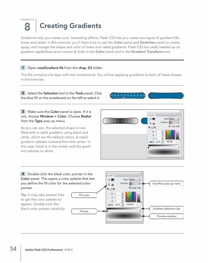
Make sure the Color panel is open. If it isnot, choose Window > Color. Choose Radialfrom the Type pop-up menu.
As you can see, the selected shape is nowfilled with a radial gradient, using black andwhite, which are the default colors. A radialgradient radiates outward from the center. Inthis case, black is in the center, and the gradi-ent radiates to white.
Double-click the black color pointer in theColor panel. This opens a color palette that letsyou define the fill color for the selected colorpointer.
Tip: It may take several tries to get the color palette to appear. Double-click the black color pointer carefully!
4
3
2
1
54 Adobe Flash CS3 Professional : H•O•T
Preview window
Gradient definition bar
Overflow pop-up menu
Fill color
Pointer
03_FlashCS3HOT_(22-65).qxd 08/08/2007 01:03 PM Page 54

Select a shade of red in the colorpalette.
As you can see, the appearance of theradial gradient changes to range fromred to white instead of ranging fromblack to white. You have just createdyour first custom gradient! Next youwill use the Gradient Transform tool toedit the appearance of the gradient.
Select the Gradient Transform tool from the Free Transform pop-up menu in the Tools panel. Usethe various edit handles to change the center point, width, radius, rotation, and focal point of the gradi-ent fill. Experiment with each of the edit handles to get the hang of how each controls the appearance of the gradient fill.
Next you will make a linear gradient.
Select the Selection tool in the Tools panel. Click the blue fill on the snowboard on the right side onthe Stage to select it.7
6
5
55Chapter 3 : Using the Drawing and Color Tools
Center point Focal point handle
Width handle
Rotation handle
Radius handle
03_FlashCS3HOT_(22-65).qxd 08/08/2007 01:03 PM Page 55

In the Color panel, choose Linearfrom the Type pop-up menu.
As you can see, this option creates a linear gradient using the same colors you used for the previous gradient.
Make sure the Swatches panel is visible. If it’s not, choose Window >Swatches. Choose Add Swatch from theColor Options menu to save the currentlyselected gradient in the Color Swatchespanel so you can access it easily.
Select the GradientTransform tool in the Toolspanel. Modify the width, rota-tion, and center point handlesto become familiar with howthey modify the appearance ofthe linear gradient fill.
When you’re finished, close newGradient.fla. You don’t need to save your changes.11
10
9
8
56 Adobe Flash CS3 Professional : H•O•T
New gradient
Center point Rotation handle
Width handle
03_FlashCS3HOT_(22-65).qxd 08/08/2007 01:03 PM Page 56

57Chapter 3 : Using the Drawing and Color Tools
N O T E : New Gradient Features in Flash CS3
In addition to new features in the Gradient Transform tool, Flash CS3 now supportsthe use of gradients containing up to 15 colors, which lets you create much morecomplicated and colorful gradients. Create additional colors in your gradients byclicking below the Gradient Definition bar in the Color panel. A new color, repre-sented by the color pointer, will appear after each click.
Flash CS3 provides three new options for controlling how gradient overflow, the colors that extend beyond the limits of the gradient, should be handled. The optionsare Normal (Windows) or Extend (Mac), which is the default; Mirror (Windows) orReflect (Mac); and Repeat. You can generate an overflow in your gradients by select-ing them with the Gradient Transform tool and decreasing their widths by draggingthe width handles.
Gradient definition barPointers
Overflow
Mirror
Normal Width handle
Overflow
Gradient limit
03_FlashCS3HOT_(22-65).qxd 08/08/2007 01:03 PM Page 57
9E X E R C I S E
Drawing with the Pen Tool
The Pen tool creates more complex shapes by combining both straight and curved lines in the sameshape. Shapes created with the Pen tool consist of paths, anchor points, and tangent handles, which youcan modify with the Subselection tool. (You’ll learn more about the Subselection tool in Exercise 10.)
If you’ve used other vector-based drawing programs, such as FreeHand or Illustrator, you’ll be instantlycomfortable with the Pen tool in Flash CS3 because it works the same way. If you haven’t used the Pentool before, it can take some practice before you become really comfortable with it.
In this exercise, you will start by learning how to use the Pen tool to draw a few basic geometric shapes.By the end of this exercise, you will be more comfortable working with the Pen tool to create more com-plex shapes of your own.
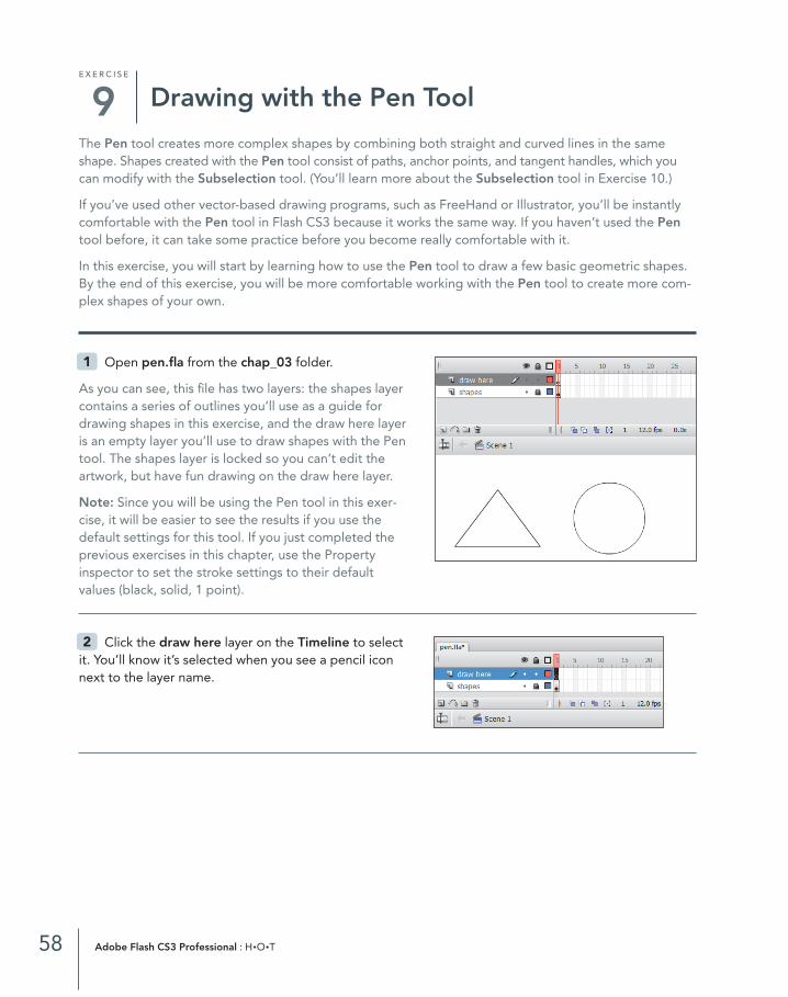
Open pen.fla from the chap_03 folder.
As you can see, this file has two layers: the shapes layercontains a series of outlines you’ll use as a guide fordrawing shapes in this exercise, and the draw here layeris an empty layer you’ll use to draw shapes with the Pentool. The shapes layer is locked so you can’t edit theartwork, but have fun drawing on the draw here layer.
Note: Since you will be using the Pen tool in this exer-cise, it will be easier to see the results if you use thedefault settings for this tool. If you just completed theprevious exercises in this chapter, use the Property inspector to set the stroke settings to their default values (black, solid, 1 point).
Click the draw here layer on the Timeline to selectit. You’ll know it’s selected when you see a pencil iconnext to the layer name.
2
1
58 Adobe Flash CS3 Professional : H•O•T
03_FlashCS3HOT_(22-65).qxd 08/08/2007 01:03 PM Page 58

Select the Pen tool in the Tools panel.
Move your cursor to the lower-left corner of the triangle outline, and click.
A small circle appears. This is the first anchor point, indicating the beginning of your line. Line segments are created between pairs of anchor points to create shapes.
Click the top corner of the triangle to add the second anchor point.
The line segment appears as a red line with two square anchor points on either end on top of the line segment, which is the stroke color in the Property inspector and in the Tools panel you set in Step 1. The red line indicates the line segment is selected.
Click the lower-right corner of the triangle to create a second line segment between the upper-right and lower-right anchor points.
Position the cursor over the lower-left corner of the triangle where you created the first anchor point in Step 4. A small circle appears beside the cursor, indicating the path will be closed if you click. Click to close the path and create the shape.
Note: In Flash CS3, when you close a path, the shape will not automatically fill with the currently selectedfill color in the Property inspector or in the Tools panel. You must apply fill colors separately.
Next, you’ll learn to draw a circle with the Pen tool, which can be a bit more complicated than drawing a triangle and may take some time to master. Don’t worry if you have to do this exercise a few timesbefore you get the hang of things.
7
6
5
4
3
59Chapter 3 : Using the Drawing and Color Tools
Anchor point
Closing a path
Line segment withtwo anchor points
03_FlashCS3HOT_(22-65).qxd 08/08/2007 01:03 PM Page 59
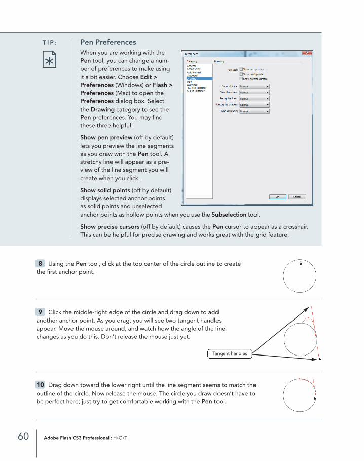
Using the Pen tool, click at the top center of the circle outline to create the first anchor point.
Click the middle-right edge of the circle and drag down to add another anchor point. As you drag, you will see two tangent handles appear. Move the mouse around, and watch how the angle of the line changes as you do this. Don’t release the mouse just yet.
Drag down toward the lower right until the line segment seems to match the outline of the circle. Now release the mouse. The circle you draw doesn’t have to be perfect here; just try to get comfortable working with the Pen tool.
10
9
8
60 Adobe Flash CS3 Professional : H•O•T
T I P : Pen PreferencesWhen you are working with thePen tool, you can change a num-ber of preferences to make usingit a bit easier. Choose Edit >Preferences (Windows) or Flash >Preferences (Mac) to open thePreferences dialog box. Selectthe Drawing category to see thePen preferences. You may findthese three helpful:
Show pen preview (off by default)lets you preview the line segmentsas you draw with the Pen tool. Astretchy line will appear as a pre-view of the line segment you willcreate when you click.
Show solid points (off by default)displays selected anchor points as solid points and unselectedanchor points as hollow points when you use the Subselection tool.
Show precise cursors (off by default) causes the Pen cursor to appear as a crosshair.This can be helpful for precise drawing and works great with the grid feature.
Tangent handles
03_FlashCS3HOT_(22-65).qxd 08/08/2007 01:03 PM Page 60

Click the middle-bottom edge of the circle to add another anchor point. The linewill curve when you add the third anchor point to complete half of the circle shape.
Drag up on the middle-left edge of the circle to add another anchor point. Asyou drag, you will see two tangent handles appear. Don’t release the mouse just yet.
Drag up toward the top left until the line segment seems to match the outlineof the circle. Release the mouse.
Move the cursor to the first anchor point you created at the top of the circle. When you see the smallcircle appear next to the Pen tool pointer, click to close the path, and drag the handles until the linematches the outline of the circle.
Select the Paint Bucket tool, and fill the circle with the currently selected fill color.
Save your changes, and keep pen.fla open for the next exercise. Don’t worry if the circle you createdisn’t perfect.
Next you’ll learn how to modify lines using the shapes you just made.
16
15
14
13
12
11
61Chapter 3 : Using the Drawing and Color Tools
03_FlashCS3HOT_(22-65).qxd 08/08/2007 01:03 PM Page 61

10E X E R C I S E
Modifying Paths
In the previous exercise, you learned how to create shapes using the Pen tool. Next, you’ll learn how toreshape them using the Selection and Subselection tools to modify paths using their anchor points ortangent handles.
If you just completed Exercise 9, pen.fla should still be open. If it’s not, complete Exercise 9, andthen return to this exercise.
Select the Paint Bucket tool in the Tools panel. Click inside the triangle to fill it with the currentlyselected fill color.
Choose the Selection tool. Position the cursor over the left side of the triangle.
Notice the cursor changes to a small curved line. This line indicates you are over aline segment.
Drag the line segment to the left. The shape will start todistort and stretch as you continue to drag. When you releasethe mouse, notice both the line and the fill have changed their shapes.
The Selection tool offers a free-form way of transforming shapes. Although it can be fun to use, it lacksthe precision you sometimes need when creating complex shapes. When you need pinpoint precision,use the Subselection tool. The Subselection tool lets you manipulate the anchor points and tangent han-dles of paths after you have added them.
4
3
2
1
62 Adobe Flash CS3 Professional : H•O•T
T I P : What Do the Icons Associated with the Subselection Tool Mean?The Subselection tool edits paths and anchor points created with the Pen tool. Asyou learn to edit paths, anchor points, and tangent handles with the Subselectiontool, you will notice that the cursor often changes as you work with it. The followingchart outlines the cursors associated with the Subselection tool:
Selects a path
Selects an anchor point
Modifies the tangent handle(s)
03_FlashCS3HOT_(22-65).qxd 08/08/2007 01:03 PM Page 62

Select the Subselection tool in the Tools panel.
Position the cursor over the edge of the circle shape. A small black square appears, indicating you are over a line.
Click the edge of the circle to select it. Notice the anchor points are now visible. The anchor points are represented by small red squares along the line of the circle.
Note: Flash CS3 adds anchor points, if necessary, to create curves, which is why you might see more than four anchor points on your artwork.
Position the cursor over the middle-right anchor point. A small white squareappears next to the cursor when you are directly over the anchor point.
Click to select the middle-right anchor point. When you do, the tangent handles for that anchor point appear.
Click and drag the top tangent handle of the middle-right anchor point to the right. When you release the mouse, you’ll notice the top and bottom portions of the curve change together. This is the normal behavior of tangent handles.
10
9
8
7
6
5
63Chapter 3 : Using the Drawing and Color Tools
The black square on thecursor indicates a line.
Red squares indicateanchor points.
Tangent handles
03_FlashCS3HOT_(22-65).qxd 08/08/2007 01:03 PM Page 63

Click to select the middle-left anchor point.
Hold down the Alt key (Windows) or the Opt key(Mac), and click and drag the top tangent handle ofthe middle-left anchor point to the left. When yourelease the mouse, you’ll notice only the top portionchanges.
As you can see, holding down the Alt key (Windows)or the Opt key (Mac) lets you modify one part of a curve without affecting the other.
Click the anchor point on the middle right of the circle,and drag down to try to match the circle image in the back-ground. You can click and drag an anchor point to make thecircle more perfect in shape.
Now you know how to use the Selection and Subselection tools to modify the lines you create in Flash CS3. With the Selection tool, you can reshape straight orcurved lines by dragging the lines themselves. The Subselection tool lets you reshape by clicking andmoving the anchor points and tangent handles. Next you will learn how to add, remove, and convertanchor points.
Select the Subselection tool in the Tools panel. Position the tool over the rounded side of the trian-gle shape. Click to select the path.
In addition to drawing shapes, the Pen tool can add anchor points to a line.
14
13
12
11
64 Adobe Flash CS3 Professional : H•O•T
Modifying a singletangent handle.
T I P : What Do the Icons Associated with the Pen Tool Mean?As you create paths, anchor points, and tangent handles with the Pen tool, the cursor will change. The following chart outlines each of the cursor icons associatedwith the Pen tool:
Draws straight and curved paths to create objects
Adds anchor points to paths
Deletes anchor points from paths
Closes a path
Converts a corner point to a curve point, and vice versa
03_FlashCS3HOT_(22-65).qxd 08/08/2007 01:03 PM Page 64

Select the Pen tool in the Tools panel. Notice that whenyou move the Pen tool directly over the selected path, asmall plus sign appears next to the cursor. Click to add a newanchor point.
Note: You can also add an anchor point by selecting the Add Anchor Point tool from the Pen tool pop-up menu in the Tools panel.
Converting curves to straight lines is a rather simple process and one you should know how to do. You’lllearn how in the following steps.
Position the cursor over the newly added anchor point, and notice that a smallcaret (^) symbol appears, indicating you will convert the curve point to a cornerpoint if you click.
Note: You can also convert an anchor point by selecting the Convert Anchor Point tool from the Pen pop-up menu in the Tools panel.
Double-click the anchor point to convert the anchor point to a corner point,transforming the curve into a straight-edged shape. Because you converted theanchor point to a corner point, you’ll no longer have access to any tangent handles.
Converting a corner point to a curve point is even easier to do—you’ll do that next.
Select the Subselection tool in the Tools panel. Click the anchor point toselect it. Hold down the Alt key (Windows) or the Opt key (Mac), and click anddrag up the anchor point you just modified. When you do this, you will convert the corner point to an anchor point.
Note: Make sure the anchor point is still selected before you drag it. Selected anchor points are filled.
With the anchor point still selected, press Delete to remove the anchor point.
Close pen.fla. You don’t need to save your changes.
By now, you should feel pretty comfortable working with the drawing and color tools in Flash CS3. If youaren’t quite there yet, feel free to practice and play some more with the different tools and color set-tings. You might try drawing some artwork for a project you want to create in Flash CS3. Nothing willever replace good old-fashioned practice.
20
19
18
17
16
15
65Chapter 3 : Using the Drawing and Color Tools
New anchor point
03_FlashCS3HOT_(22-65).qxd 08/08/2007 01:03 PM Page 65