uwe – uml-based web engineering
DESCRIPTION
Chapter 7UML-BASED WEB ENGINEERINGAn Approach Based on StandardsNora Koch,1,2 Alexander Knapp,1 Gefei Zhang,1 Hubert Baumeister31Institut f¨ur Informatik, Ludwig-Maximilians-Universit¨at M¨unchen, Germany{kochn,knapp,zhangg}@pst.ifi.lmu.de2F.A.S.T. GmbH, M¨unchen, [email protected] og Matematisk Modellering, Danmarks Tekniske Universitet, Lyngby, [email protected]TRANSCRIPT

Chapter 7
UML-BASED WEB ENGINEERING
An Approach Based on Standards
Nora Koch,1,2 Alexander Knapp,1 Gefei Zhang,1 Hubert Baumeister3
1Institut fur Informatik, Ludwig-Maximilians-Universitat Munchen, Germany{kochn,knapp,zhangg}@pst.ifi.lmu.de2F.A.S.T. GmbH, Munchen, [email protected] og Matematisk Modellering, Danmarks Tekniske Universitet, Lyngby, [email protected]
7.1 OverviewUML-based Web Engineering (UWE, www.pst.ifi.lmu.de/
projekte/uwe) came up by the end of the nineties (Baumeister et al.,1999; Wirsing et al., 1999) with the idea to find a standard way for buildinganalysis and design models of Web systems based on the then current methodsOOHDM (Schwabe and Rossi, 1995), RMM (Isakowitz et al., 1995), andWSDM (de Troyer and Leune, 1998). The aim, which is still pursued, wasto use a common language or at least to define metamodel-based mappingsamong the existing approaches (Koch and Kraus, 2003; Escalona and Koch,2006).
At that time the Unified Modeling Language (UML) which evolved fromthe integration of the three different modeling approaches of Booch, OOSE andOMT seemed to be a promising approach for system modeling. Since the earlyintegration efforts, the UML became the “lingua franca” of (object-oriented)software engineering (Object Management Group, 2005). A prominent featureof UML is that it provides a set of aids for the definition of domain-specificmodeling languages (DSL) – so called extension mechanisms. Moreover thenewly defined DSLs remain UML-compliant, which allows the use of all UMLfeatures supplemented, e.g., with Web specific extensions.
158
Both the acceptance of the UML as a standard in the development of soft-ware systems and the flexibility provided by the extension mechanisms are thereasons for the choice of the Unified Modeling Language instead of the use ofproprietary modeling techniques. The idea followed by UWE to adhere to stan-dards is not limited to UML. UWE uses also XMI as model exchange format(in the hope of future tool interoperability enabled by a truly portable XMI),MOF for metamodeling, the model-driven principles given by OMG’s Model-Driven Architecture (MDA) approach, the transformation language QVT, andXML.
UWE is continuously adapting, on the one hand, to new features of Web sys-tems, such as more transaction-based, personalized, context-dependent, andasynchronous applications. On the other hand, UWE evolves to incorpo-rate the state of the art of software engineering techniques, such as aspect-oriented modeling, integration of model checking using Hugo/RT (Knappet al., 2002, www.pst.ifi.lmu.de/projekte/hugo), and new modeltransformation languages to improve design quality.
The remainder of this chapter is structured as follows: The features distin-guishing UWE’s development process, visual notation and tool support, arebriefly outlined below. UWE’s modeling techniques are discussed step by stepin Sect. 7.2 by means of a simple online movie database case study. The UWEextensions of the UML metamodel are outlined in Sect. 7.3. UWE’s model-driven process and, in particular, the model transformations integrated into theprocess are described in Sect. 7.4. The CASE tool ArgoUWE which supportsthe UWE notation and method is described in Sect. 7.5. Finally, we give anoutlook on future steps in the development of UWE.
7.1.1 Characteristics of the ProcessThe development of Web systems is subject to continuous changes in user
and technology requirements. Models built so far in any stage of the develop-ment process have to be easily adaptable to these changes. To cope efficientlywith the required flexibility, UWE advocates a strict separation of concerns inthe early phases of the development and implements a model-driven develop-ment process, i.e. a process based on the construction of models and modeltransformations. The ultimate challenge is to support a development processthat allows fully automated generation of Web systems.
Separation of Concerns Similarly to other Web engineering methods,the UWE process is driven by the separate modeling of concerns describing aWeb system. Models are built at the different stages of requirements engineer-ing, analysis, design, and implementation of the development process, and areused to represent different views of the same Web application correspondingto the different concerns (content, navigation structure, and presentation). The

UML-Based Web Engineering 159
Views
Phases
Content
Presentation
Analysis
Adaptivity
ImplementationDesign
Navigation structure
Structure
Behavior
Aspects
Figure 7.1. Modeling dimensions in UWE (Schwinger and Koch, 2006)
content model is used to specify the concepts that are relevant to the applica-tion domain and the relationships between these concepts. The hypertext ornavigation structure is modeled separately from the content, although it is de-rived from the content model. The navigation model represents the navigationpaths of the Web system being modeled. Presentation specification takes intoaccount representation and user-machine communication tasks.
UWE proposes at least one type of UML diagram for the visualization ofeach model to represent the structural aspects of the different views. How-ever, in addition very often UML interaction diagrams or state machines areused to represent behavioral aspects of the Web system. Figure 7.1 shows howthe scope of modeling spans these three orthogonal dimensions: developmentstages, system’s views, and aspects. Another concern also handled separatelyis adaptivity. Personalized and context-dependent Web systems provide theuser with more appropriate information, links, or pages by being aware of useror contextual features. We propose to view adaptivity as a cross-cutting con-cern and thus to use aspect-oriented techniques to model adaptive Web sys-tems. It can be seen as a fourth dimension influencing all other Web modelingdimensions: views, aspects, and phases. Requirements models and architec-ture models focusing on specific Web aspects complete the specification of theWeb system. Separation of concerns offers advantages in the maintenance andre-engineering of a Web system as well as for the generation of Web systemsfor different contexts and platforms.
Development Driven by Models The model-driven development(MDD) approach not only advocates the use of models (as those describedabove) for the development of software, but also emphasizes the need of trans-formations in all phases of the development, from requirements specificationto designs and from design models to implementations. Transformations be-
160
tween models provide a chain that enables the automated implementation of asystem in successive steps from the different models.
The development of Web systems is a field which lends itself to apply-ing MDD due to the Web-specific separation of concerns and continuouschanges in technologies in the Web domain. Metamodel-based methods suchas OO-H (Gomez et al., 2001) and UWE constitute a good basis for theimplementation of a model-driven process for the development of Web sys-tems. They included semi-automated model-based transformations even beforeMDD concepts became well-known. For the first guidelines for a systematicand stepwise construction of models for UWE we refer to Hennicker and Koch,2001 and Koch, 2001.
UWE emphasizes the relevance of requirements engineering starting withmodeling activities in this early development phase (Escalona and Koch,2006). Therefore the UWE metamodel includes a set of modeling primitivesthat allows for simpler and more specific specification of the requirements ofWeb systems.
7.1.2 Characteristics of the NotationA picture is worth a thousand words. Visual models are naturally used not
only for documentation purposes but also as the crucial chain link in the soft-ware development process. The trend is the production of domain-specificvisual models. Conversely, the importance of the selection of the modelinglanguage is not self-evident.
From our point of view, a modeling language has to:
1 provide powerful primitives to construct expressive, yet intuitive models;
2 offer wide CASE tool support;
3 facilitate extension;
4 provide a formal or at least a semi-formal semantics;
5 be easy to learn.
Although UML only fulfills the first three requirements, it seems that UMLis currently the best approach. UML and various UML extensions are suc-cessfully used in many different application domains. However, there is noformal semantics covering the whole UML and the fifth requirement can onlybe satisfied, if we restrict ourselves to a subset of the modeling constructs ofUML.
Modeling with UML The distinguishing feature of UWE is its UMLcompliance since the model elements of UWE are defined in terms of a UML

UML-Based Web Engineering 161
profile and as an extension of the UML metamodel (Koch and Kraus, 2002;Koch and Kraus, 2003).
Although the UML is expressive enough to model all requirements thatarise in modeling Web systems, it does not offer Web-domain-specific ele-ments. To ease the modeling of special aspects of Web applications, we definein UWE special views – using UML’s extension mechanisms – graphically rep-resented by UML diagrams, such as the navigation model and the presentationmodel (Koch, 2001; Koch et al., 2001).
UML modeling techniques comprise the construction of static and dynamicviews of software systems by object and class diagrams, component and de-ployment diagrams, use case diagrams, state and activity diagrams, sequenceand communication diagrams. The UML extension mechanisms are used todefine stereotypes that we utilize for the representation of Web constructs, suchas nodes and links. In addition, tag definitions and constraints written in OCL(Object Constraint Language) can be used. This way we obtain a UML com-pliant notation – a so called UML “lightweight” extension or better known asUML profile. UWE notation is defined as such a UML profile.
The advantage of using UML diagrams is the common understanding ofthese diagrams. Furthermore, the notation and the semantics of the model-ing elements of “pure” UML, i.e., those modeling elements that comprise theUML metamodel, are widely described in the OMG documentation (ObjectManagement Group, 2005). For any software designer with UML backgroundit is easy to understand a model based on a UML profile, such as the extensionthat UWE suggests. We observe that UML extensions “inherit” the problemsof UML, e.g., the lack of a complete formal semantics covering all modelingelements.
UWE focuses on visual modeling together with systematic design and auto-matic generation. The aim is to cover the entire development life cycle of Websystems providing techniques and notations to start with requirements models,moving through design models as well as including architecture and aspectmodels. All these models are visualized using UML diagrammatic techniques.
Metamodeling Metamodeling plays a fundamental role in CASE toolconstruction and is as well the core of the model-driven process. A metamodelis a precise definition of the elements of a modeling language, their relation-ships and the well-formedness rules needed for creating syntactically correctmodels.
Tool-supported design and model-based system generation is becoming es-sential in the development process of Web systems due to the need of rapidproduction of new Web presences and Web applications. CASE tools have tobe built on a precisely specified metamodel of the modeling constructs usedin the design activities, providing more flexibility if modeling requirements
162
change. Metamodels are essential for the definition of model transformationsand automatic code generation.
The UWE metamodel is defined as a conservative extension of the UMLmetamodel (Koch and Kraus, 2003). It is the basis for the UWE notation andUWE tool support. Conservative means that the modeling elements of theUML metamodel are not modified, e.g., by adding additional features or as-sociations to the UML modeling element Class. OCL constraints are used tospecify additional static semantics (analogous to the well-formedness rules inthe UML specification). By staying thereby compatible with the MOF inter-change metamodel we can take advantage of metamodeling tools based on thecorresponding XML interchange format (XMI).
In addition, the UWE metamodel is “profileable” (Baresi et al., 2002),which means that it is possible to map the metamodel to a UML profile. AUML profile consists of a hierarchy of stereotypes and a set of constraints.Stereotypes are used for representing instances of metaclasses and are writtenin guillemets, like �menu� or �anchor�. The definition of a UML profilehas the advantage that it is supported by nearly every UML CASE tool eitherautomatically, by a tool plug-in or passively when the model is saved and thenchecked by an external tool. The UWE metamodel could be also used as basisfor building a common metamodel (or ontology) of the concepts needed forthe design in the Web domain (cf. Koch and Kraus, 2003; Escalona and Koch,2006). Using for this purpose the standardized OMG metamodeling architec-ture would facilitate the construction of meta CASE tools.
7.1.3 Characteristics of the Tool EnvironmentThe UML compliance of UWE has an important advantage: all CASE tools
which support the Unified Modeling Language can be used to build UWE mod-els. For this purpose it is sufficient to name stereotypes after the names of theUWE modeling concepts. Many tools offer additional support with an importfunctionality of pre-defined UML profiles. In such a case the profile modelelements can be used in the same way as the built-in UML model elements.
CASE Tool Support A wider developer support is achieved by the opensource plug-in ArgoUWE (www.pst.ifi.lmu.de/projekte/uwe) forthe open source CASE tool ArgoUML (www.argouml.org). In addition toproviding an editor for the UWE notation, ArgoUWE checks the consistencyof models and supports the systematic transformation techniques of the UWEmethod. Using the UWE profile, models designed with other UML CASE toolscan be exchanged with ArgoUWE. The use of tools that support not only themodeling itself but also a model-driven approach shortens development cyclesand facilitates re-engineering of Web systems.
UML-Based Web Engineering 163
Model Consistency Check ArgoUWE also checks the consistency ofmodels according to the OCL constraints specified for the UWE metamodel.Consistency checking is embedded into the cognitive design critics feature ofArgoUML and runs in a background thread. Thus, model deficiencies andinconsistencies are gathered during the modeling process but the designer isnot interrupted. The designer obtains feedback at any time by taking a look atthis continuously updated list of design critiques, which is shown in the to-dopane of the tool.
In the following, we exemplify how UWE’s model-driven process, notation,and tool support are used to develop Web applications.
7.2 Method by Case StudyWe use a simple online movie database example that allows users to explore
information about movies and persons related to the production of the movies.This example is inspired by www.imdb.org and named the “Movie UWECase study” (MUC). Movies are characterized, among others, by their genre,the cast, memorable quotes, trailers, and a soundtrack. Persons related to themovie production are the director, producer, composer, and the actors. Theuser interested in watching a movie can access information on theaters thatshow the movie. Registered users – identified by an email and a password –can provide comments, rate comments, vote movies, manage “their movies”,and buy tickets in theaters of their preference. The MUC online movie databasepersonalizes the application giving some recommendations about movies andproviding personalized news to the user.
The focus in the following is on the models built for the different viewsof the analysis and design phases (see Fig. 7.1). Model transformations aredescribed as part of the model-driven process in Sect. 7.4.
7.2.1 Starting with Requirements SpecificationThe first step towards developing a Web system is the identification of the
requirements for such an application that are specified in UWE with a require-ments model. Requirements can be documented at different levels of detail.UWE proposes two levels of granularity when modeling Web system require-ments. First, a rough description of the functionalities is produced, which aremodeled with UML use cases. In a second step, a more detailed descriptionof the use cases is developed, e.g., by UML activity diagrams that depict theresponsibilities and actions of the stakeholders.
Overview of Use Cases Use case diagrams are built with the UML el-ements Actor and UseCase. Actors are used to model the users of the Web

164
system. Typical users of Web systems are the anonymous user (called User)in the MUC case study, the registered user (RegisteredUser) and the Web sys-tem administrator. Use cases are used to visualize the functionalities that thesystem will provide. The use case diagram depicts use cases, actors, and asso-ciations among them showing the roles the actors play in the interaction withthe system, e.g., triggering some use cases.
In addition to the UML features, UWE distinguishes between three typesof use cases: navigation, process and personalized use cases. Navigation usecases are used to model typical user behavior when interacting with a Web ap-plication, such as browsing through the Web application content or searchinginformation by keywords. The use case model of Fig. 7.2 for example includesthe �navigation� ( ) use cases ViewMovie, Search and GoToExternalSite. Pro-
Figure 7.2. UWE use case model for MUC
UML-Based Web Engineering 165
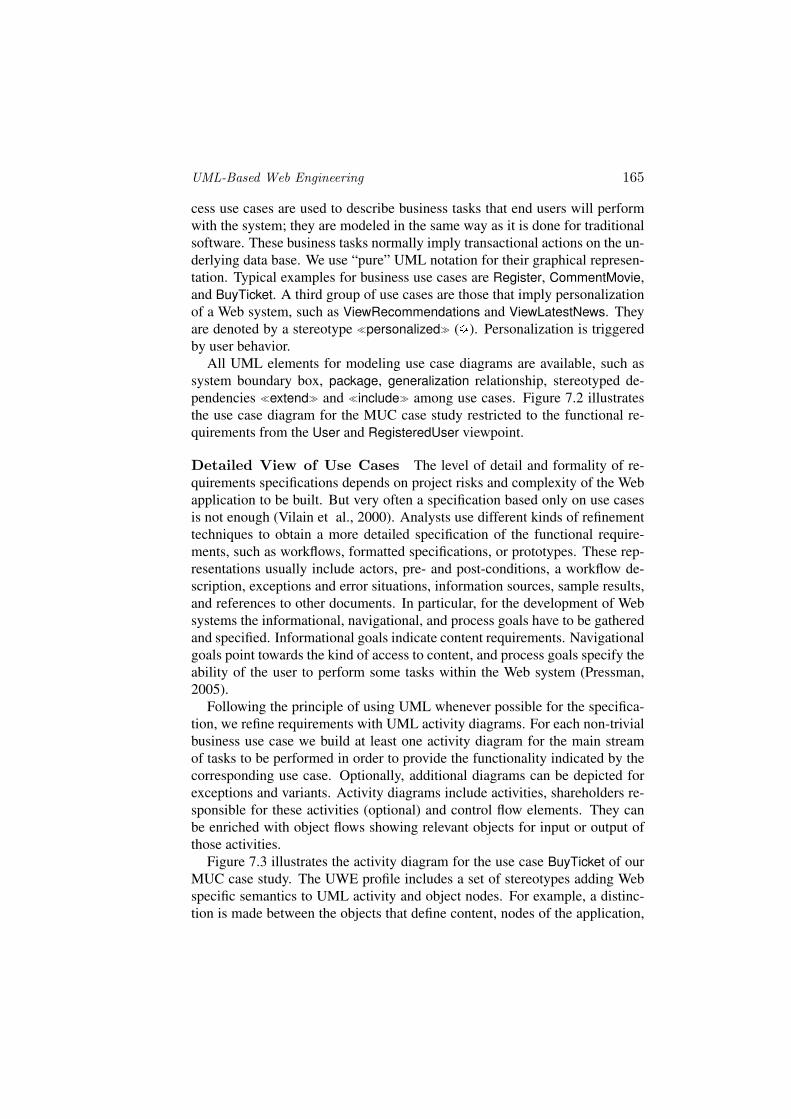
cess use cases are used to describe business tasks that end users will performwith the system; they are modeled in the same way as it is done for traditionalsoftware. These business tasks normally imply transactional actions on the un-derlying data base. We use “pure” UML notation for their graphical represen-tation. Typical examples for business use cases are Register, CommentMovie,and BuyTicket. A third group of use cases are those that imply personalizationof a Web system, such as ViewRecommendations and ViewLatestNews. Theyare denoted by a stereotype �personalized� ( ). Personalization is triggeredby user behavior.
All UML elements for modeling use case diagrams are available, such assystem boundary box, package, generalization relationship, stereotyped de-pendencies �extend� and �include� among use cases. Figure 7.2 illustratesthe use case diagram for the MUC case study restricted to the functional re-quirements from the User and RegisteredUser viewpoint.
Detailed View of Use Cases The level of detail and formality of re-quirements specifications depends on project risks and complexity of the Webapplication to be built. But very often a specification based only on use casesis not enough (Vilain et al., 2000). Analysts use different kinds of refinementtechniques to obtain a more detailed specification of the functional require-ments, such as workflows, formatted specifications, or prototypes. These rep-resentations usually include actors, pre- and post-conditions, a workflow de-scription, exceptions and error situations, information sources, sample results,and references to other documents. In particular, for the development of Websystems the informational, navigational, and process goals have to be gatheredand specified. Informational goals indicate content requirements. Navigationalgoals point towards the kind of access to content, and process goals specify theability of the user to perform some tasks within the Web system (Pressman,2005).
Following the principle of using UML whenever possible for the specifica-tion, we refine requirements with UML activity diagrams. For each non-trivialbusiness use case we build at least one activity diagram for the main streamof tasks to be performed in order to provide the functionality indicated by thecorresponding use case. Optionally, additional diagrams can be depicted forexceptions and variants. Activity diagrams include activities, shareholders re-sponsible for these activities (optional) and control flow elements. They canbe enriched with object flows showing relevant objects for input or output ofthose activities.
Figure 7.3 illustrates the activity diagram for the use case BuyTicket of ourMUC case study. The UWE profile includes a set of stereotypes adding Webspecific semantics to UML activity and object nodes. For example, a distinc-tion is made between the objects that define content, nodes of the application,

166
Figure 7.3. MUC case study: UWE activity diagram detailing the buy-ticket use case
and presentation elements. Visualization is improved by the use of the corre-sponding icons: for �content�, for �node�, and for Web user interface(�WebUI�). Stereotypes of activities are used to distinguish possible actionsof the user in the Web environment: browse, search, and transactional activitiesthat comprise changes in at least one database. To this category of stereotypesbelong: for �browse�, for �query�, and for transactional actions.
7.2.2 Defining the ContentAnalysis models provide the basis for the design models, in particular the
content model of a Web system. The aim of the content model is to provide avisual specification of the domain relevant information for the Web system thatmainly comprises the content of the Web application. However, very often itincludes also entities of the domain required for customized Web applications.These entities constitute the so-called user profile or user model. Customiza-tion not only deals with adaptation to the properties of users or user groups,but also with adaptation to features of the environment. A so called contextprofile or context model is built in such a case. The objects occuring in thedetailed view of the use cases provide natural candidates of domain entities forthe content and user model.
The separation of content and user model (or context model) has proven itsvalue in practice. Both are graphically represented as UML class diagrams.The content model of MUC is depicted in Fig. 7.4; the user model is shownin Fig. 7.5. The entities representing content and respectively user or contextproperties are modeled by classes, i.e. instances of the UML metaclass Class.
UML-Based Web Engineering 167
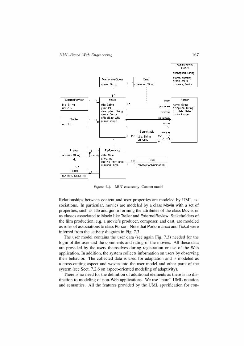
Figure 7.4. MUC case study: Content model
Relationships between content and user properties are modeled by UML as-sociations. In particular, movies are modeled by a class Movie with a set ofproperties, such as title and genre forming the attributes of the class Movie, oras classes associated to Movie like Trailer and ExternalReview. Stakeholders ofthe film production, e.g. a movie’s producer, composer, and cast, are modeledas roles of associations to class Person. Note that Performance and Ticket wereinferred from the activity diagram in Fig. 7.3.
The user model contains the user data (see again Fig. 7.3) needed for thelogin of the user and the comments and rating of the movies. All these dataare provided by the users themselves during registration or use of the Webapplication. In addition, the system collects information on users by observingtheir behavior. The collected data is used for adaptation and is modeled asa cross-cutting aspect and woven into the user model and other parts of thesystem (see Sect. 7.2.6 on aspect-oriented modeling of adaptivity).
There is no need for the definition of additional elements as there is no dis-tinction to modeling of non-Web applications. We use “pure” UML notationand semantics. All the features provided by the UML specification for con-

168
Figure 7.5. MUC case study: User model
structing class diagrams can be used, in particular, packages and enumerations(e.g. Genre in Fig. 7.4) and relationships like generalizations, compositions, orassociation classes (e.g. Cast in Fig. 7.4).
7.2.3 Laying Down the Navigation StructureBased on the requirement analysis and the content modeling, the naviga-
tion structure of a Web application is modeled. Navigation classes (visualizedas ) represent navigable nodes of the hypertext structure; navigation linksshow direct links between navigation classes. Alternative navigation pathsare handled by �menu�s ( ). Access primitives are used to reach multipleinstances of a navigation class (�index� , or �guided tour� ), or to se-lect items (�query� ). In Web applications that contain business logic thebusiness processes must be integrated into the navigation structure. The entryand exit points of the business processes are modeled by process classes ( )in the navigation model, the linkage between each other and to the navigationclasses is modeled by process links. Each process class is associated with a usecase which models a business process. Navigation structures are laid down instereotyped UML class diagrams with navigation and process classes, menus,and access primitives extending the UML metaclass Class, and navigation andprocess links extending the UML metaclass Association.
Initial Navigation Structure UWE provides methodological guide-lines for developing an initial sketch of the navigation structure from the con-tent model of a Web application (see also Koch and Kraus, 2002; Knapp et al.,2003): Content classes deemed to be relevant for navigation are selected fromthe content model and these classes as well as their associations are put into anavigation model as navigation classes and navigation links, respectively. Nav-igation links represent possible steps to be followed by the user, and thus theselinks have to be directed; if navigation back and forth between two navigation

UML-Based Web Engineering 169
classes is desired, an association is split into two. Menus are added to everynavigation class that has more than one outgoing association. Finally, accessprimitives (index, guided tours and queries) allow for selecting a single infor-mation entity, as represented by a navigation class. An index, a guided touror a query should be added between two navigation classes whenever the mul-tiplicity of the end target of their linking association is greater than one. Theproperties of the content class corresponding to the navigation class over whichthe index or the query runs are added as navigation attributes to the navigationclass.
The result of applying these steps of the UWE method to the content modelof the MUC case study in Fig. 7.4 is shown in Fig. 7.6. From the home page
Figure 7.6. MUC case study: Navigation from Movie (fragment)
Home the user can, by means of a query SearchMovie, search for movies ofhis interest by criteria like movie name, actors, or directors etc. Soundtrack isdirectly reachable through MovieMenu as there may be at most one soundtrackfor each movie whereas there may be several directors which have to be se-lected from DirectorsIndex. As an example for a bidirectional linkage betweennavigation classes, the actors of a movie can be selected from CastIndex reach-ing a Person, where conversely all movies which this person has contributedto can be chosen from. The navigation structure has been refined by adding ahome node ( ) as the initial node of the MUC Web application, as well as amain menu.

170
The UWE profile notation for menus and access primitives provides a com-pact representation of patterns frequently used in the Web domain. Fig. 7.7(b)shows the shorthand notation for indexes. Using “pure” UML for modelingan index would instead, require an additional model element: an index item asdepicted in Fig. 7.7(a). The result would be an overloaded model if it containsmany of such indexes.
(a) “Pure” UML notation for index (b) Shorthand notation for index
Figure 7.7. UWE Profile: Index
Adding Business Processes In a next step, the navigation structurecan now be extended by process classes which represent the entry and exitpoints to business processes. These process classes are derived from the non-navigational use cases. In Fig. 7.8, the business processes Register (linked tothe use case Register) and Login (linked to the use case Login) have been added.The integration of these classes in the navigation model requires an additionalmenu (MainMenu) which provides links to Register, Login and SearchMovies.A user may only manage his movies, if he has logged in previously. Finally, auser can buy tickets for a selected movie and a selected performance by navi-gating to BuyTicket.
Figure 7.8. MUC case study: Integration of business processes into navigation (fragment)

UML-Based Web Engineering 171
A single navigation structure diagram for a whole Web application wouldinevitably lead to cognitive overload. Different views to the navigation struc-ture should be produced from the content model focusing on different aspectsof the application, like navigation to particular content or integration of relatedbusiness processes.
7.2.4 Refining the ProcessesEach process class included in the navigation model is refined into a process
model consisting of a process flow model and optionally of a process structuremodel. The control and data flow is modeled in the process flow model inthe form of an UML activity diagram. It is the result of a refinement processthat starts from the workflow in the requirements model. Figure 7.9 illustrates
Figure 7.9. MUC case study: UWE process flow model for the buy-ticket process
the result of the refinement process applied to Fig. 7.3. This process mainlyconsists in the integration of the main stream of the actions with alternatives,such as Enter new credit card info in case of invalid card numbers or exceptionhandling (not included in this example). Control elements are added with thepurpose of providing the business logic. Activities and objects can be added tothe activity diagram. A process structure model has the form of a class diagram
172
and describes the relationship between a process class and other classes whoseinstances are used to support the business process.
7.2.5 Sketching the PresentationThe presentation model provides an abstract view on the user interface (UI)
of a Web application. It is based on the navigation model and abstracts fromconcrete aspects of the UI, like the use of colors, fonts, and where the UI el-ements are placed on the Web page; instead, the presentation model describesthe basic structure of the user interface, i.e., which UI elements (e.g. text, im-ages, anchors, forms) are used to present the navigation nodes. The advantageof the presentation model is that it is independent of the actual techniques usedto implement the Web site, thus allowing the stakeholders to discuss the appro-priateness of the presentation before actually implementing it.
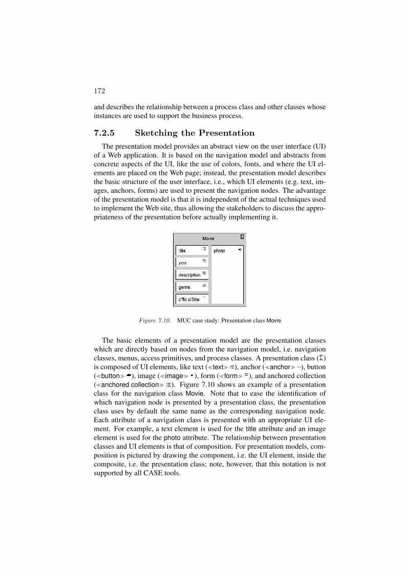
Figure 7.10. MUC case study: Presentation class Movie
The basic elements of a presentation model are the presentation classeswhich are directly based on nodes from the navigation model, i.e. navigationclasses, menus, access primitives, and process classes. A presentation class ( )is composed of UI elements, like text (�text� ), anchor (�anchor� ), button(�button� ), image (�image� ), form (�form� ), and anchored collection(�anchored collection� ). Figure 7.10 shows an example of a presentationclass for the navigation class Movie. Note that to ease the identification ofwhich navigation node is presented by a presentation class, the presentationclass uses by default the same name as the corresponding navigation node.Each attribute of a navigation class is presented with an appropriate UI ele-ment. For example, a text element is used for the title attribute and an imageelement is used for the photo attribute. The relationship between presentationclasses and UI elements is that of composition. For presentation models, com-position is pictured by drawing the component, i.e. the UI element, inside thecomposite, i.e. the presentation class; note, however, that this notation is notsupported by all CASE tools.
UML-Based Web Engineering 173
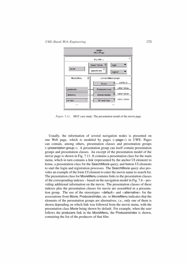
Figure 7.11. MUC case study: The presentation model of the movie page
Usually, the information of several navigation nodes is presented onone Web page, which is modeled by pages (�page�) in UWE. Pagescan contain, among others, presentation classes and presentation groups(�presentation group�). A presentation group can itself contain presentationgroups and presentation classes. An excerpt of the presentation model of themovie page is shown in Fig. 7.11. It contains a presentation class for the mainmenu, which in turn contains a link (represented by the anchor UI element) tohome, a presentation class for the SearchMovie query, and button UI elementsto start the login and registration processes. The SearchMovie query also pro-vides an example of the form UI element to enter the movie name to search for.The presentation class for MovieMenu contains links to the presentation classesof the corresponding indexes – based on the navigation model in Fig. 7.6 – pro-viding additional information on the movie. The presentation classes of theseindexes plus the presentation classes for movie are assembled in a presenta-tion group. The use of the stereotypes �default� and �alternative� for theassociations from Movie, ProducersIndex, etc. to MovieMenu indicates that theelements of the presentation groups are alternatives, i.e., only one of them isshown depending on which link was followed from the movie menu, with thepresentation class Movie being shown by default. For example, when the userfollows the producers link in the MovieMenu, the ProducersIndex is shown,containing the list of the producers of that film.
174
7.2.6 Aspect-Oriented Modeling of AdaptivityAdaptivity is an increasingly important feature of Web applications. Adap-
tive Web applications provide more appropriate pages to the user by beingaware of user or context properties. An example of adaptivity are recommen-dations based on user behavior, like movie of favorite actors in our MUC casestudy. In general, adaptivity is orthogonal to the three views: content, navi-gation structure, and presentation (see Fig. 7.1). In order to model adaptivefeatures of Web applications non-invasively, we use techniques of Aspect-Oriented Modeling (AOM, cf. Filman et al., 2004) in UWE.
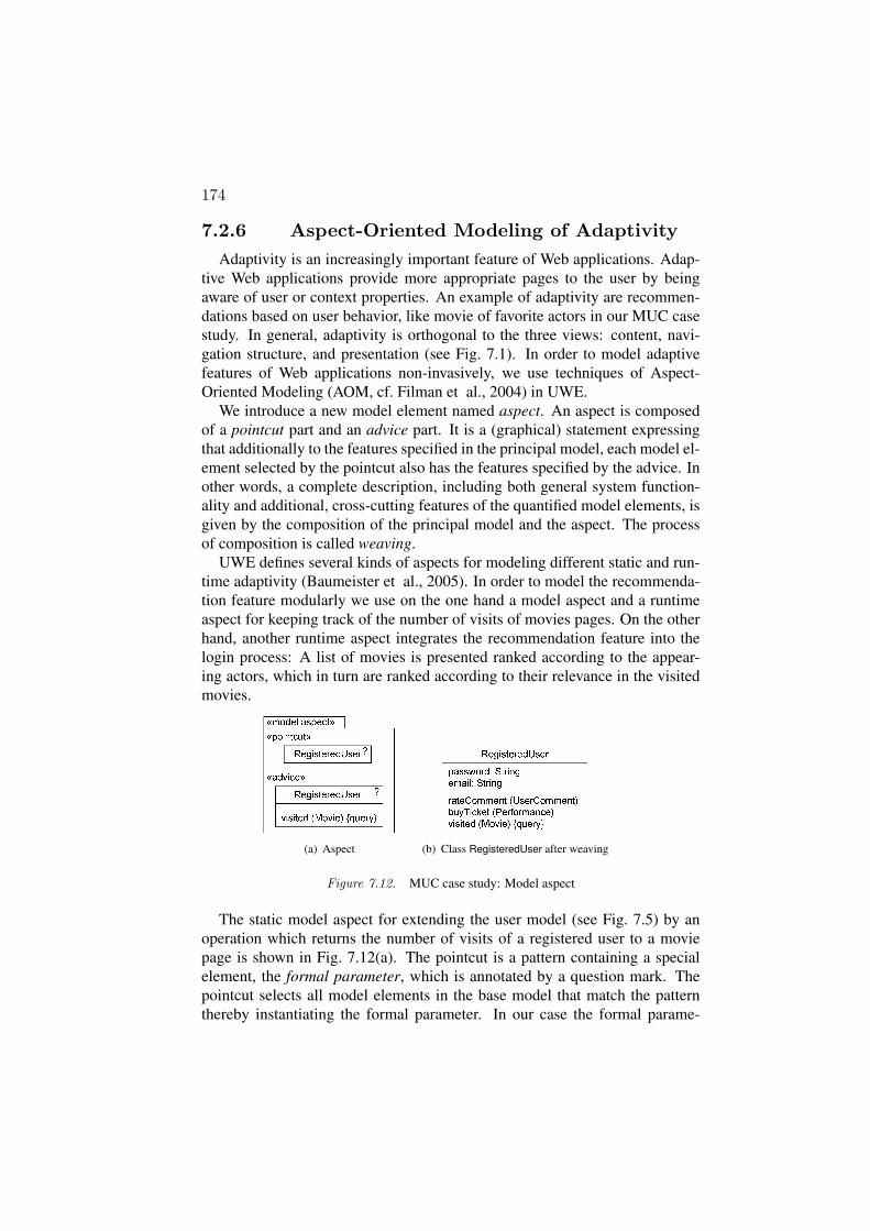
We introduce a new model element named aspect. An aspect is composedof a pointcut part and an advice part. It is a (graphical) statement expressingthat additionally to the features specified in the principal model, each model el-ement selected by the pointcut also has the features specified by the advice. Inother words, a complete description, including both general system function-ality and additional, cross-cutting features of the quantified model elements, isgiven by the composition of the principal model and the aspect. The processof composition is called weaving.
UWE defines several kinds of aspects for modeling different static and run-time adaptivity (Baumeister et al., 2005). In order to model the recommenda-tion feature modularly we use on the one hand a model aspect and a runtimeaspect for keeping track of the number of visits of movies pages. On the otherhand, another runtime aspect integrates the recommendation feature into thelogin process: A list of movies is presented ranked according to the appear-ing actors, which in turn are ranked according to their relevance in the visitedmovies.
(a) Aspect (b) Class RegisteredUser after weaving
Figure 7.12. MUC case study: Model aspect
The static model aspect for extending the user model (see Fig. 7.5) by anoperation which returns the number of visits of a registered user to a moviepage is shown in Fig. 7.12(a). The pointcut is a pattern containing a specialelement, the formal parameter, which is annotated by a question mark. Thepointcut selects all model elements in the base model that match the patternthereby instantiating the formal parameter. In our case the formal parame-

UML-Based Web Engineering 175
ter is a class of which only the name RegisterdUser is specified. The point-cut therefore selects all classes (actually, there is exactly one such class) inthe navigation model with the name RegisteredUser. The advice defines thechange to the selected model elements. After weaving, our RegisteredUserclass is thus extended by the operation visited, see Fig. 7.12(b); no other ele-ments are affected by this aspect. Model aspects are a special case of aspect-oriented class diagrams (AOCDs), which are also defined in a lightweightUML extension and therefore UML compatible, see (Zhang, 2005). Since amodel aspect specifies a static modification of the base model, other, stan-dardized model transformation languages such as the Atlas TransformationLanguage (ATL [Jouault and Kurtev, 2005]), QVT-P (QVT-Partners, 2003), orQVT (QVT-Merge Group, 2004) may also be used. The advantage of AOCDcompared with these languages is, however, that it does not require the modelerto have expert knowledge of the UML metamodel, which may make AOCDeasier to use (cf. Sect. 7.4).
Figure 7.13. MUC case study: Link traversal aspect for counting movie visits
The dynamic behavior of our MUC system is extended by two runtime as-pects. Figure 7.13 shows a link traversal aspect, used to ensure that visitedreturns the correct result: the pointcut selects all links from any object – notethat neither the name nor the type of the object to the left is specified and thusit matches any object – to some Movie object. The advice defines with an OCLconstraint the result of the action fired when such a link is visited: if the cur-rent user is logged in, the system increases his respective record by one. Afterweaving, the behavior of the system is thus enriched by counting user visits tothe movie pages.
Figure 7.14 shows how the business process Login is extended by a flowaspect. The base model depicted in Fig. 7.14(a) defines the normal workflowwithout considering adaptivity: the user is asked to input his email addressand password, then the system verifies the input and responds accordingly.The adaptive feature of generating recommendations for the user is added bythe aspect shown in Fig. 7.14(b). The pointcut selects every (in this concreteexample, exactly one) control flow edge from a decision point to the OK ac-tion, which is guarded by the condition valid. The advice deletes this edge by

176
crossing it out and adds an action for recommendation generation and two newcontrol flow edges to bind it into the process.
(a) Base model
(b) Aspect adding recommendation generation
Figure 7.14. MUC case study: Flow aspect extending Login
7.3 UWE MetamodelThe UWE metamodel is defined as a conservative extension of the UML 2.0
metamodel. Conservative means that the model elements of the UML meta-model are not modified. Instead, all new model elements of the UWE meta-model are related by inheritance to at least one model element of the UMLmetamodel. We define additional features and relationships for the new ele-ments. Analogous to the well-formedness rules in the UML specification, weuse OCL constraints to specify the additional static semantics of these new el-ements. The resulting UWE metamodel is profileable, which means that it ispossible to map the metamodel to a UML profile (Koch and Kraus, 2003). Inparticular, UWE stays compatible with the MOF interchange metamodel andtherefore with tools that are based on the corresponding XML interchange for-mat XMI. The advantage is that all standard UML CASE tools which supportUML profiles or UML extension mechanisms can be used to create UWE mod-els of Web applications. If technically possible, these CASE tools can furtherbe extended to support the UWE method. ArgoUWE, see Sect. 7.5, presents aninstance of such CASE tool support for UWE based on the UWE metamodel.

UML-Based Web Engineering 177
Figure 7.15. Overview of the UWE metamodel
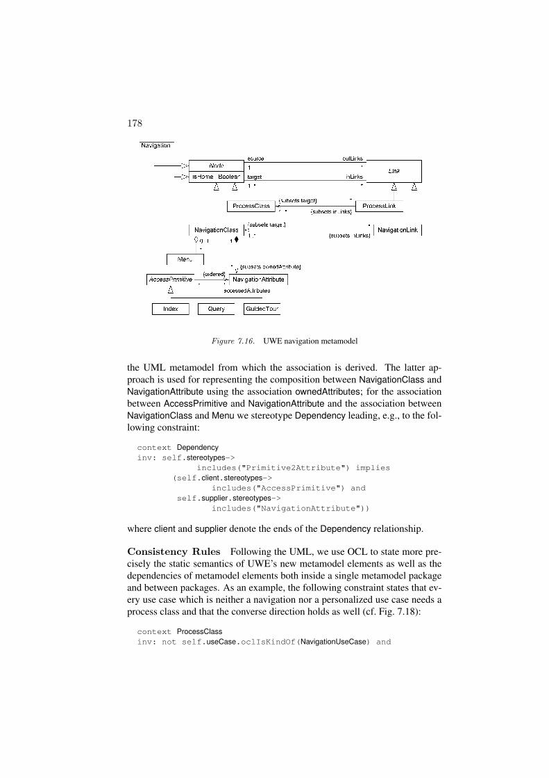
The UWE extension of the UML metamodel consists of adding two top-level packages Core and Adaptivity to the UML, cf. Fig. 7.15. The separa-tion of concerns of Web applications is reflected by the package structure ofCore, the cross-cutting of adaptation by the dependency of Adaptivity on Core(see Fig. 7.1). The package Requirements comprises the UWE extensions onUseCase for discerning navigational from business process and personalizeduse cases and the different markings for ActivityNode (�browse�, �query�,and �transaction�) and ObjectNode (�content�, �node�, and �WebUI�),see Escalona and Koch, 2006. The navigation and presentation packages bun-dle UWE’s extensions for the corresponding models. Figure 7.16 details a partof the metamodel for Navigation with the connection between Node and Linkand their various subclasses. NavigationClass and ProcessClass with the re-lated NavigationLink and ProcessLink as well as Menu and the access primitivesIndex, GuidedTour and Query provide the Web domain specific metaclasses forbuilding the navigation model. Packages Contents and Process are currentlyonly used as a stub, reflecting the fact that UWE allows the designer to developcontent and process models using all UML features. Finally, Adaptation con-tains UWE’s aspect facilities by representing Aspect as a UML Package withtwo subpackages Pointcut and Advice.
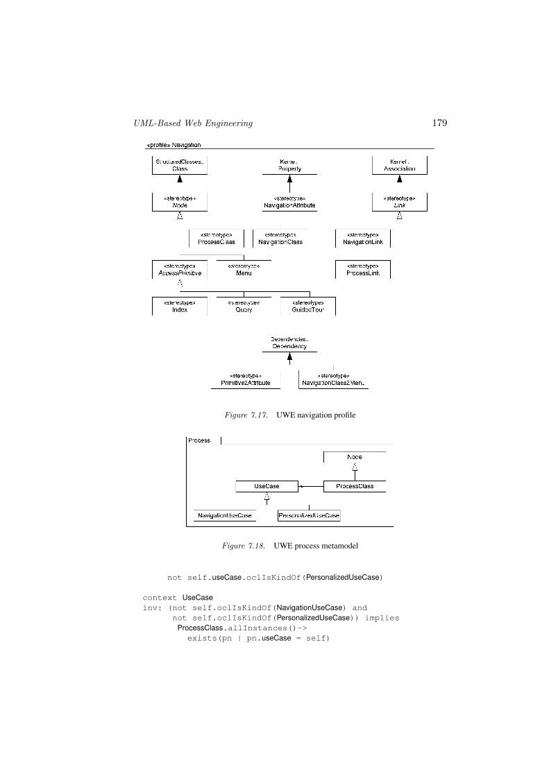
In order to transfer the UWE metamodel into a UML profile we use UML’sextension mechanisms (see Sect. 7.1). Figure 7.17 shows how the meta-classes of the UWE navigation metamodel are rendered as a stereotype hi-erarchy, forming the UWE navigation profile: Node becomes a stereotypeof Class, NavigationAttribute a stereotype of Property, and Link a stereo-type of Association. The associations of the UWE navigation metamodel,e.g., connecting Link to Node cannot be represented by meta-associations(see Object Management Group, 2005) and have to be added either by stereo-typing the UML metaclass Dependency or by using the association from
178
Figure 7.16. UWE navigation metamodel
the UML metamodel from which the association is derived. The latter ap-proach is used for representing the composition between NavigationClass andNavigationAttribute using the association ownedAttributes; for the associationbetween AccessPrimitive and NavigationAttribute and the association betweenNavigationClass and Menu we stereotype Dependency leading, e.g., to the fol-lowing constraint:
context Dependencyinv: self.stereotypes->
includes("Primitive2Attribute") implies(self.client.stereotypes->
includes("AccessPrimitive") andself.supplier.stereotypes->
includes("NavigationAttribute"))
where client and supplier denote the ends of the Dependency relationship.
Consistency Rules Following the UML, we use OCL to state more pre-cisely the static semantics of UWE’s new metamodel elements as well as thedependencies of metamodel elements both inside a single metamodel packageand between packages. As an example, the following constraint states that ev-ery use case which is neither a navigation nor a personalized use case needs aprocess class and that the converse direction holds as well (cf. Fig. 7.18):
context ProcessClassinv: not self.useCase.oclIsKindOf(NavigationUseCase) and
UML-Based Web Engineering 179
Figure 7.17. UWE navigation profile
Figure 7.18. UWE process metamodel
not self.useCase.oclIsKindOf(PersonalizedUseCase)
context UseCaseinv: (not self.oclIsKindOf(NavigationUseCase) and
not self.oclIsKindOf(PersonalizedUseCase)) impliesProcessClass.allInstances()->exists(pn | pn.useCase = self)
180
7.4 Model-Driven Development in UWEThe UWE approach includes the specification of a process for the develop-
ment of Web systems in addition to the UML profile and the UWE metamodel.The UWE process is model-driven following the MDA principles and usingseveral other OMG standards, like MOF, UML, OCL, and XMI, and forth-coming standards, like QVT (QVT-Merge Group, 2004). The process relies onmodeling and model transformations, and its main characteristic is the system-atic and semi-automatic development of Web systems as detailed in this bookin the chapter on model-driven Web engineering by N. Moreno et al. The aimof such an MDD process is automatic model transformation which in each stepis based on transformation rules.
Focusing on model transformations the UWE process is depicted inFig. 7.19 as a stereotyped UML activity diagram (Melia et al., 2005). Mod-els are shown as objects, and transformations are represented with stereotypedactivities (special circular icon).
The process starts with the business model, which MDA calls computa-tional independent model (CIM), used to specify the requirements. Platform-independent models (PIMs) are derived from these requirement models. Theset of design models represents the different concerns of the Web applicationscomprising: the content, the navigation, the business processes, the presenta-tion, and the adaptation of the Web system (summarized as FunctionalModelsin Fig. 7.19). In a next step, the different views are integrated into a “bigpicture” model of the Web systems, which can be used for validation (Knappand Zhang, 2006) and also for generation of platform-dependent models (seebelow). A merge with architectural modeling features, either of the “big-picture model” or the design models directly, results in an integrated PIMcovering functional and architectural aspects. Finally, the platform-specificmodels (PSMs) derived from the integration model are the starting point forcode generation.
7.4.1 Transformations from Requirements toFunctional Models
The overall objective of modeling the requirements is the specification ofthe system as a CIM and to provide input for the construction of models inthe other development phases (see Figs. 7.1, 7.19, and Sect. 7.2). In particular,specific objectives for Web systems are the specification of content require-ments, the specification of the functional requirements in terms of navigationneeds and business processes, the definition of interaction scenarios for differ-ent groups of Web users, and if required, the specification of personalizationand context adaptation. The first model transformation step of the UWE pro-cess consists of mapping these Web system requirements models to the UWE

UML-Based Web Engineering 181
:Model for Struts
«PIM to PSM»Integration2Struts
:Model for J2EE
«CIM to PIM»Req2Architecture
:ArchitectureModels
«PIM to PIM»IntegratingBigPicture&Architecture
«PIM to PSM»
«CIM to PIM»Req2Functionality
«PIM to PIM»Functionality2BigPicture
:FunctionalModels
:...
«PIM to PIM»FunctionalityRefinement
PIM
CIM
PSM
:IntegrationModel
:Requirements Model
«PIM to PSM»Integration2J2EE
:BigPictureModel
Figure 7.19. Overview of model transformations in the UWE process
functional models. Transformation rules are defined therefore as mappingsfrom the requirements metamodel package to the content, navigation, presenta-tion, process, and adaptivity packages of the metamodel. How these packagesdepend on each other is shown in Fig. 7.15.
For example, UWE distinguishes in the requirements model between differ-ent types of navigation functionality: browsing, searching, and transactionalactivities. Browse actions can be used to enforce the existence of a navigationpath between source and target node. An action of type search indicates theneed of a query in the navigation model in order to allow for user input of aterm and the system responding with a resulting set matching this term (seeSect. 7.2.1).
Figure 7.20 shows the Search2Query transformation rule specified in QVT’sgraphical notation (QVT-Merge Group, 2004). Source and target of the trans-formation is the UWE metamodel defined as checkonly and enforce, respec-tively (identified with an “c” and “e” in Fig. 7.20). For each search with con-

182
Figure 7.20. Transformation rule Search2Query
tent p2 in the requirements model, a query in the navigation model is generatedwith an associated navigation attribute p2. For the associated node object inthe requirements model, an index and objects of a navigation class, as well ascorresponding links will be generated.
For more details about the UWE metamodel for Web requirements we referthe reader to Escalona and Koch, 2006. A detailed description of the trans-formation rules between CIMs and PIMs for the functional aspects of Webapplications has been presented in Koch et al., 2006. A metamodel of the non-functional requirements for Web applications and mappings of non-functionalrequirements to architectural model elements are subject to future work.
7.4.2 Refinement of Functional ModelsThe transformations for refining the functional models comprise mappings
from content to navigation model, refinements of the navigation model, andfrom the navigation into the presentation model. In UWE, an initial navigationmodel is generated based on classes of the content model marked as navigationrelevant (see Sect. 7.2.3). This generation step can be rendered as a transfor-mation Content2Navigation. From a single content model different navigationviews can be obtained, e.g., for different stakeholders of the Web system likeanonymous user, registered user, and administrator. The generation of eachnavigation view requires a set of marks on elements of the content model whichform a so-called marking model kept separately from the content model. The
UML-Based Web Engineering 183
development process cannot be completed in an entirely automatic way, as thedesigner has to take the decision about the “navigation relevance” marks; theContent2Navigation transformation is applied once the marks have been set.
Conversely, the remaining transformation steps for navigation models men-tioned in Sect. 7.2.3 are turned into transformation rules that can be appliedfully automatically. These rules include for example the insertion of indexesand menus. Presentation elements are generated from navigation elements.For example, for each link in the navigation model an appropriate anchor isrequired in the presentation model. The main difficulty is the introduction ofthe look and feel aspects.
All these transformations are defined as OCL constraints (by preconditionsand postconditions) in UWE and are implemented in Java in the CASE toolArgoUWE.
7.4.3 Creation of Validation and IntegrationModels
The UWE MDD process comprises two main integration steps: the inte-gration of all functional models and the integration of functional and non-functional aspects; the latter integration step is related to architectural designdecisions.
The aim of the first step is the creation of a single model for validating thecorrectness of the different functional models and that allows seamless creationof PSMs. This “big picture” model is a UML state machine, representing thecontent, navigation structure, and the business processes of the Web applica-tion as a whole (presentation aspects will be added in the future). The statemachine can be checked by the tool Hugo/RT (Knapp et al., 2002) – a UMLmodel translator for model checking, theorem proving, and code generation.
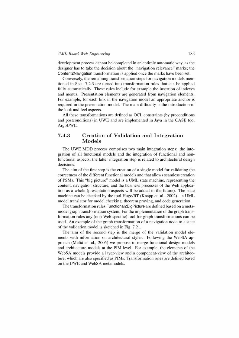
The transformation rules Functional2BigPicture are defined based on a meta-model graph transformation system. For the implementation of the graph trans-formation rules any (non-Web specific) tool for graph transformations can beused. An example of the graph transformation of a navigation node to a stateof the validation model is sketched in Fig. 7.21.
The aim of the second step is the merge of the validation model ele-ments with information on architectural styles. Following the WebSA ap-proach (Melia et al., 2005) we propose to merge functional design modelsand architecture models at the PIM level. For example, the elements of theWebSA models provide a layer-view and a component-view of the architec-ture, which are also specified as PIMs. Transformation rules are defined basedon the UWE and WebSA metamodels.
184
Figure 7.21. Transformation rule Node2State
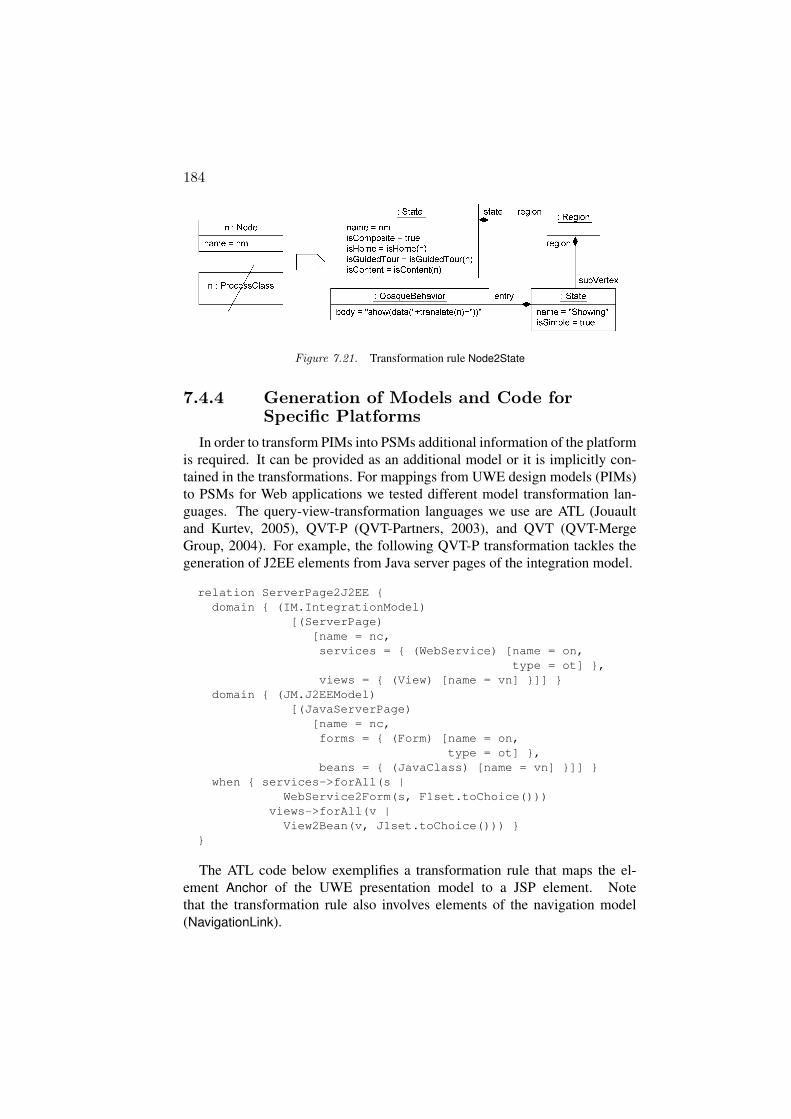
7.4.4 Generation of Models and Code forSpecific Platforms
In order to transform PIMs into PSMs additional information of the platformis required. It can be provided as an additional model or it is implicitly con-tained in the transformations. For mappings from UWE design models (PIMs)to PSMs for Web applications we tested different model transformation lan-guages. The query-view-transformation languages we use are ATL (Jouaultand Kurtev, 2005), QVT-P (QVT-Partners, 2003), and QVT (QVT-MergeGroup, 2004). For example, the following QVT-P transformation tackles thegeneration of J2EE elements from Java server pages of the integration model.
relation ServerPage2J2EE {domain { (IM.IntegrationModel)
[(ServerPage)[name = nc,services = { (WebService) [name = on,
type = ot] },views = { (View) [name = vn] }]] }
domain { (JM.J2EEModel)[(JavaServerPage)
[name = nc,forms = { (Form) [name = on,
type = ot] },beans = { (JavaClass) [name = vn] }]] }
when { services->forAll(s |WebService2Form(s, F1set.toChoice()))
views->forAll(v |View2Bean(v, J1set.toChoice())) }
}
The ATL code below exemplifies a transformation rule that maps the el-ement Anchor of the UWE presentation model to a JSP element. Notethat the transformation rule also involves elements of the navigation model(NavigationLink).

UML-Based Web Engineering 185
rule Anchor2JSP {fromuie : UWE!Anchor
(not uie.presentationClass.oclIsUndefined() andnot uie.navigationLink.oclIsUndefined())
tojsp : JSP!Element
(name <- ’a’,children <- Sequence { hrefAttribute,
contentNode }),hrefAttribute : JSP!Attribute(name <- ’href’,value <- thisModule.createJSTLURLExpr(uie.navigationLink.target.name,’objID’)),
contentNode : JSP!TextNode(value <- uie.name)
}
7.5 CASE Tool ArgoUWEWe have extended the CASE tool ArgoUML into a tool for UWE-based Web
application development, called ArgoUWE (Knapp et al., 2003, www.pst.ifi.lmu.de/projekte/argouwe). We decided to extend ArgoUMLas it is a feature-rich, open-source tool and offers a plugin architecture. Thedrawback of this decision is that the UWE metamodel can not be used directlysince ArgoUML is based on UML 1.3/4. However, a UML 1.x compatibleprofile can easily be derived from the UWE metamodel along the same linesas sketched in Sect. 7.3.
ArgoUML provides support for designing Web applications in the phasesof requirements elicitation and content, navigation, business process as wellas presentation modeling. It provides not only tailored editors for UWE di-agrams, but also semi-automatic model transformations defined in the UWEdevelopment process. As these model transformations are based on the UWEmetamodel, the tool ensures both consistency between the different modelsand integrity of the overall Web application model with respect to UWE’sOCL constraints. ArgoUWE fully integrates the UWE metamodel (Koch andKraus, 2003) and provides XMI export, and thus facilitates data transfer withother UML-compliant tools. Design deficiencies, such as violations of theOCL constraints, are reported by an extension of the cognitive design critics ofArgoUML and can also be checked upon request (see Sect. 7.5.2).
Working with ArgoUWE is intuitive for ArgoUML users, as ArgoUWEmakes use of the graphical interface of ArgoUML. In particular, the UMLmodel elements and diagrams are structured in a tree view in the explorer ((1)in Fig. 7.22); the diagrams are edited in the editor pane (2); to-do items of thedesigner are listed in the to-do pane (3); tagged values, constraints, and doc-
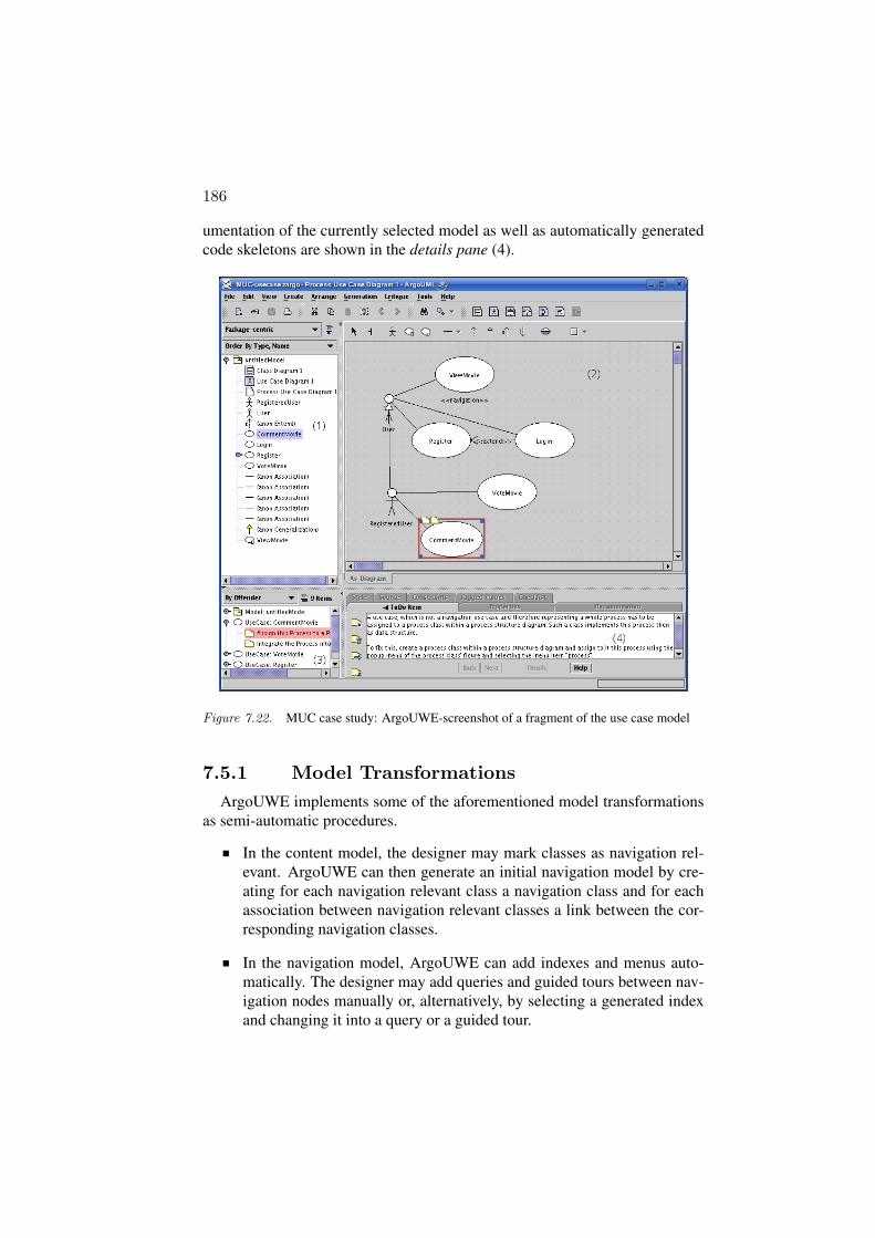
186
umentation of the currently selected model as well as automatically generatedcode skeletons are shown in the details pane (4).
Figure 7.22. MUC case study: ArgoUWE-screenshot of a fragment of the use case model
7.5.1 Model TransformationsArgoUWE implements some of the aforementioned model transformations
as semi-automatic procedures.
In the content model, the designer may mark classes as navigation rel-evant. ArgoUWE can then generate an initial navigation model by cre-ating for each navigation relevant class a navigation class and for eachassociation between navigation relevant classes a link between the cor-responding navigation classes.
In the navigation model, ArgoUWE can add indexes and menus auto-matically. The designer may add queries and guided tours between nav-igation nodes manually or, alternatively, by selecting a generated indexand changing it into a query or a guided tour.

UML-Based Web Engineering 187
From the navigation model, ArgoUWE can generate a first draft of apresentation model. For each navigation class and each of its attributesa presentation class is created. The presentation classes of attributes areassociated to those of the navigation classes by composition.
The generation of Web applications from the presentation model is out ofscope for ArgoUWE. This is done either by hand by the Web designer or semi-automatically by using frameworks for the implementation of Web applica-tions, such as Struts (www.struts.apache.org).
7.5.2 Model ConsistencyAn important requirement of any CASE tool is to support the modeler to
keep his models consistent. Upon model inconsistency, the tool may eitherinterrupt the modeler and force him first to correct it before continuing mod-eling, or simply give a warning. We implemented ArgoUWE to do the lattersince we believe that the usability of the modeler being warned yet not in-terrupted outweighs the drawback of the model being inconsistent for a shorttime. Moreover, the ArgoUML feature of design critics provides an excel-lent starting point for the implementation of the non-interruptive warnings forUWE models.
The “cognitive design critics” of ArgoUML is one of its distinguishing fea-tures compared to other modeling tools (cf. Robbins, 1999). During run time,a thread running in the background keeps checking if the current model showsdeficiencies. For each deficiency found, a design critique item is created andadded to the to-do pane. Design critics not only warn the user that his designmay be improved but can also, by means of a wizard, lead to a better design.The design critique items range from incompleteness, such as unnamed modelelements, to inconsistency, such as name collisions of different attributes oroperations in a class. Furthermore, design critics also suggest the use of cer-tain design patterns (Gamma et al., 1995). The issues of design critics can besorted by several criteria like priority or the model element causing the designcritique. Design critiques are only warnings and do not interrupt the designer.
ArgoUWE inherits the feature of design critics from ArgoUML. In fact,all well-formedness constraints of UWE have been fully integrated and arecontinuously checked by ArgoUWE in the background at runtime. In Fig. 7.22the highlighted design critique indicates that the use case CommentMovie doesnot show a corresponding process class yet; this critique corresponds to themetamodel constraints shown in Sect. 7.3.
7.6 OutlookThe UML-based Web Engineering (UWE) approach is continuously evolv-
ing. Evolution is due to: improvement of existing features, such as person-
188
alization of Web systems; adaptation to new technologies, as asynchronousclient-server communication; and introduction of new software engineeringtechniques like aspect-orientation and model-driven principles. The challengein all these cases is to provide a more intuitive and useful tool for the method-ological development of Web systems, to increase Web systems quality and toreduce development time.
The evolution we can currently observe is driven by a set of improvementsthat are being addressed and a set of extensions we are planning for UWE. Themost important are:
Specification of the transformations (at metamodel level) of (non-functional) requirements to architecture models.
Implementation of the “weaving” process for the integration of theaspect-oriented features in UWE models.
Engineering of Rich Internet Applications (RIAs), e.g. Web applicationsbased on asynchronous communication like using AJAX (Garrett, 2005).
Tool support for transformations from CIM models to PIM models andfor the UML 2.0 features in UWE.
Integration of a QVT engine (when available) in the tool environment.
Extension of UWE with test models.
Our higher-level goal is the convergence of Web design/development meth-ods. It is the only way to obtain a powerful domain-specific modeling anddevelopment language that benefits from the advantages of the different meth-ods. Obviously, there is a trend towards using UML as the common notationlanguage. Some methods are moving from their proprietary notation to a UMLcompliant one and introduce a UML profile; others define a MOF-based meta-model. It is currently hard to predict how far this converging trend will go andwhether it will eventually lead to a “Unified Web Modeling Language”.
AcknowledgmentsThanks go to Andreas Kraus for providing the ATL transformation rule and
fruitful discussions. This work has been partially supported by the projectMAEWA “Model Driven Development of Web Applications” (WI841/7-1)of the Deutsche Forschungsgemeinschaft (DFG), Germany and the EC 6thFramework project SENSORIA “Software Engineering for Service-OrientedOverlay Computers” (FET-IST 016004).
UML-Based Web Engineering 189
ReferencesBaresi, Luciano, Garzotto, Franca, Mainetti, Luca, and Paolini, Paolo (2002).
Meta-modeling Techniques Meet Web Application Design Tools. InKutsche, Ralf-Detlef and Weber, Herbert, editors, Proc. 5th Int. Conf. Fun-damental Approaches to Software Engineering (FASE’02), volume 2306 ofLect. Notes Comp. Sci., pages 294–307. Springer, Berlin.
Baumeister, Hubert, Knapp, Alexander, Koch, Nora, and Zhang, Gefei (2005).Modelling Adaptivity with Aspects. In Lowe and Gaedke, 2005, pages 406–416.
Baumeister, Hubert, Koch, Nora, and Mandel, Luis (1999). Towards a UMLExtension for Hypermedia Design. In France, Robert and Rumpe, Bernhard,editors, Proc. 2nd Int. Conf. Unified Modeling Language (UML’99), volume1723 of Lect. Notes Comp. Sci., pages 614–629. Springer, Berlin.
de Troyer, Olga and Leune, Corneli Jan (1998). WSDM: A User Centered De-sign Method for Web Sites. Computer Networks, 30(1–7):85–94.
Escalona, Marıa Jose and Koch, Nora (2006). Metamodeling the Requirementsof Web Systems. In Proc. 2nd Int. Conf. Web Information Systems and Tech-nologies (WebIST’06), Setubal, Portugal.
Filman, Robert E., Elrad, Tzilla, Clarke, Siobhan, and Aksit, Mehmet, editors(2004). Aspect-Oriented Software Development. Addison-Wesley, Reading,Mass., &c.
Gamma, Erich, Helm, Richard, Johnson, Ralph, and Vlissides, John (1995).Design Patterns. Addison-Wesley, Boston, &c.
Garrett, Jesse James (2005). Ajax: A New Approach to Web Applications.http://www.adaptivepath.com/publications/essays/archives/000385.php.
Gomez, Jaime, Cachero, Cristina, and Pastor, Oscar (2001). Conceptual Mod-eling of Device-Independent Web Applications. IEEE Multimedia, 8(2):26–39.
Hennicker, Rolf and Koch, Nora (2001). Systematic Design of Web Applica-tions with UML. In Siau, Keng and Halpin, Terry A., editors, Unified Mod-eling Language: Systems Analysis, Design and Development Issues, pages1–20. Idea Group.
Isakowitz, Tomas, Stohr, Eduard A., and Balasubramanian, P. (1995). RMM: AMethodology for Structuring Hypermedia Design. Comm. ACM, 38(8):34–44.
Jouault, Frederic and Kurtev, Ivan (2005). Transforming Models with ATL.In Bruel, Jean-Michel, editor, Revised Sel. Papers Satellite Events at theMoDELS 2005 Conf., volume 3844 of Lect. Notes Comp. Sci., pages 128–138. Springer, Berlin.

190
Knapp, Alexander, Koch, Nora, Moser, Flavia, and Zhang, Gefei (2003). Ar-goUWE: A CASE Tool for Web Applications. In Proc. 1st Int. Wsh. Engi-neering Methods to Support Information Systems Evolution (EMSISE’03),Geneve. 14 pages.
Knapp, Alexander, Merz, Stephan, and Rauh, Christopher (2002). ModelChecking Timed UML State Machines and Collaborations. In Damm,Werner and Olderog, Ernst Rudiger, editors, Proc. 7th Int. Symp. FormalTechniques in Real-Time and Fault Tolerant Systems, volume 2469 of Lect.Notes Comp. Sci., pages 395–416. Springer, Berlin.
Knapp, Alexander and Zhang, Gefei (2006). Model Transformations for Inte-grating and Validating Web Application Models. In Mayr, Heinrich C. andBreu, Ruth, editors, Proc. Modellierung 2006 (MOD’06), volume P-82 ofLect. Notes Inform., pages 115–128. Gesellschaft fur Informatik.
Koch, Nora (2001). Software Engineering for Adaptive Hypermedia Systems:Reference Model, Modeling Techniques and Development Process. PhD the-sis, Ludwig-Maximilians-Universitat Munchen.
Koch, Nora and Kraus, Andreas (2002). The Expressive Power of UML-basedWeb Engineering. In Schwabe, Daniel, Pastor, Oscar, Rossi, Gustavo, andOlsina, Luis, editors, Proc. 2nd Int. Wsh. Web-Oriented Software Technology(IWWOST’02), pages 105–119. CYTED.
Koch, Nora and Kraus, Andreas (2003). Towards a Common Metamodel forthe Development of Web Applications. In Lovelle, Juan Manuel Cueva,Rodrıguez, Bernardo Martın Gonzalez, Aguilar, Luis Joyanes, Gayo, JoseEmilio Labra, and del Puerto Paule Ruiz, Marıa, editors, Proc. Int. Conf.Web Engineering (ICWE’03), volume 2722 of Lect. Notes Comp. Sci., pages495–506. Springer, Berlin.
Koch, Nora, Kraus, Andreas, and Hennicker, Rolf (2001). The Au-thoring Process of the UML-based Web Engineering Approach. InSchwabe, Daniel, editor, Proc. 1st Int. Wsh. Web-Oriented Software Tech-nology (IWWOST’01). http://www.dsic.upv.es/˜west2001/iwwost01/.
Koch, Nora, Zhang, Gefei, and Escalona, Marıa Jose (2006). Model Trans-formations from Requirements to Web System Design. In Wolber, Dave,Calder, Neil, Brooks, Chris, and Ginige, Athula, editors, Proc. 6th Int. Conf.Web Engineering (ICWE’06), pages 281–288. ACM.
Lowe, David and Gaedke, Martin, editors (2005). Proc. 5th Int. Conf. WebEngineering (ICWE’05), volume 3579 of Lect. Notes Comp. Sci. Springer,Berlin.
Melia, Santiago, Kraus, Andreas, and Koch, Nora (2005). MDA Transforma-tions Applied to Web Application Development. In Lowe and Gaedke, 2005,pages 465–471.
UML-Based Web Engineering 191
Object Management Group (2005). Unified Modeling Language. www.uml.org.
Object Management Group (2005). Unified Modeling Language: Super-structure, version 2.0. Specification, OMG. http://www.omg.org/cgi-bin/doc?formal/05-07-04.
Pressman, Roger (2005). Software Engineering — A Practitioner’s Approach.McGraw-Hill, Boston–Singapore, 6th edition.
QVT-Merge Group (2004). Revised Submission for MOF 2.0 Query/Views/Transformations RFP (ad/2002-04-10). Submission, OMG. http://www.omg.org/cgi-bin/doc?ad/04-04-01.pdf.
QVT-Partners (2003). Revised Submission for MOF 2.0 Query/Views/Transformations RFP (ad/2002-04-10). Submission, OMG. http://qvt.org.
Robbins, Jason Elliot (1999). Cognitive Support Features for Software Devel-opement Tools. PhD thesis, University of California, Irvine.
Schwabe, Daniel and Rossi, Gustavo (1995). The Object-Oriented HypermediaDesign Model. Comm. ACM, 38(8):45–46.
Schwinger, Wieland and Koch, Nora (2006). Modelling of Web Applications.In Kappel, Gerti, Proll, Birgit, Reich, Siegfried, and Retschitzegger, Werner,editors, Web Engineering: Systematic Development of Web Applications,pages 39–64. John Wiley, Hoboken.
Vilain, Patricia, Schwabe, Daniel, and de Souza, Clarisse Sieckenius (2000).A Diagrammatic Tool for Representing User Interaction in UML. In Evans,Andy, Kent, Stuart, and Selic, Bran, editors, Proc. 3rd Int. Conf. UnifiedModeling Language (UML’00), volume 1939 of Lect. Notes Comp. Sci.,pages 133–147. Springer, Berlin.
Wirsing, Martin, Koch, Nora, Rossi, Gustavo, Garrido, Alejandra, Mandel,Luis, Helmerich, Alfred, and Olsina, Luis (1999). Hyper-UML: Specifica-tion and Modeling of Multimedia and Hypermedia Applications in Dis-tributed Systems. In Proc. 2nd Wsh. German-Argentinian Bilateral Pro-gramme for Scientific and Technological Cooperation, Konigswinter.
Zhang, Gefei (2005). Towards Aspect-Oriented Class Diagrams. In Proc.12th Asia Pacific Software Engineering Conf. (APSEC’05), pages 763–768.IEEE.