uxo burial prediction fidelity: a summary
TRANSCRIPT

I N S T I T U T E F O R D E F E N S E A N A L Y S E S
UXO Burial Prediction Fidelity: A Summary
Jeremy A. TeichmanJenya Macheret
Shelley M. Cazares
July 2017Approved for public release;
distribution is unlimited.
IDA Document NS D-8617Log: H 17-000413
INSTITUTE FOR DEFENSE ANALYSES 4850 Mark Center Drive
Alexandria, Virginia 22311-1882

About This PublicationThis work was conducted by the Institute for Defense Analyses (IDA) under contract HQ0034-14-D-0001, Project AM-2-1528, “Assessment of Traditional and Emerging Approaches to the Detection and Classification of Surface and Buried Unexploded Ordnance (UXO),” for the Director, Environmental Security Technology Certification Program (ESTCP) and Strategic Environmental Research and Development Program (SERDP), under the Deputy Under Secretary of Defense, Installations and Environment. The views, opinions, and findings should not be construed as representing the official position of either the Department of Defense or the sponsoring organization.
For More InformationShelley M. Cazares, Project [email protected], 703-845-6792
Leonard J. Buckley, Director, Science and Technology [email protected], 703-578-2800
Copyright Notice© 2017 Institute for Defense Analyses4850 Mark Center Drive, Alexandria, Virginia 22311-1882 • (703) 845-2000.
This material may be reproduced by or for the U.S. Government pursuant to the copyright license under the clause at DFARS 252.227-7013 (a)(16) [Jun 2013].

iii
Executive Summary
Background The Strategic Environmental Research and Development Program (SERDP) has funded the development of many computational
models to predict how underwater unexploded ordnance (UXO) migrates and becomes exposed over time. A munition’s initial penetration depth into the sediment is an input into these models. Other computational models have already been developed to predict the initial penetration depth of underwater mines. SERDP would like to know if and how these existing mine models could be repurposed for UXO. Recently, IDA performed a numerical analysis for SERDP to explore the fidelity of computational models for predicting the initial penetration depth of UXO in underwater sites. This briefing provides a summary of our analysis. A separate, longer briefing gives the details.
Summary of Recommendations 1. Improve sandy sediment penetration models.
2. Develop mobility models for silt.
3. Develop mobility models for partially buried objects.
4. Develop scour burial model for silt.
5. Improve models of consolidation and creep.
6. Exercise caution in improving hydrodynamic models to support initial sediment penetration estimates—the effect of betterhydrodynamics may be dwarfed by stochasticity due to unknown precise initial conditions at the waterline.
7. Existing sediment penetration models (other than STRIKE35) are designed for near-cylindrical mines—for munitions,however, projectile-specific drag, lift, and moment coefficients are needed for estimating hydrodynamic stability and grossvelocity.

iv
8. Modules of existing depth penetration models are nearly independent and could and should be mixed and matched with littleeffort to choose best-of-breed for each regime (air/water/sediment).
9. Use simplified models with sensitivity analytic framework to understand when and how initial sediment penetrationpredictions can be improved.
10. Use regime map to evaluate whether proposed improvements in fidelity will have operational utility.

v
Contents
Introduction ..................................................................................................................................................................................................1 Overview ......................................................................................................................................................................................................2 Useful Fidelity of Initial Burial Depth .........................................................................................................................................................4
Mobility ...............................................................................................................................................................................................7 Scour ....................................................................................................................................................................................................9 Erosion .................................................................................................................................................................................................9 Combining Effects of Mobility, Scour, and Erosion .........................................................................................................................10 Map Assumptions ..............................................................................................................................................................................11 Implications .......................................................................................................................................................................................15 Risk Buckets ......................................................................................................................................................................................17
Achievable Fidelity of Initial Burial Depth ...............................................................................................................................................18 Wherre Would Additional Fidelity Help? ..................................................................................................................................................30 Summary of Recommendations .................................................................................................................................................................40 Backups ......................................................................................................................................................................................................43 Reference ................................................................................................................................................................................................ A-1

1
Introduction The Institute for Defense Analyses (IDA) is a not-for-profit company that operates three Federally Funded Research and
Development Centers. We perform scientific and technical analyses for the U.S. Government on issues related to national security.
Recently, IDA performed a numerical analysis for the Strategic Environmental Research and Development Program (SERDP) to explore the fidelity of computational models for predicting the initial penetration depth of unexploded ordnance (UXO) in underwater sites. This briefing provides a summary of our analysis. A separate, longer briefing1 describes the details of our analysis. Please contact Shelley Cazares, [email protected], 703 845 6792, for the detailed briefing.
1 S. M. Cazares, “Assessment of Traditional and Emerging Approaches to the Detection and Classification of Surface and Buried Unexploded Ordnance
(UXO),” IDA Document NS D-8616 (Alexandria, VA: Institute for Defense Analyses, forthcoming).

2
Overview
UXO mobility and exposure models depend on initial sediment penetration estimates:
What estimate fidelity (accuracy and precision) is useful forunderwater UXO remediation?
What estimate fidelity is already achievable via existingmodels developed for underwater mines?
Where (and when) would additional estimate fidelity helpunderwater UXO remediation?

3
IDA set out to answer the following questions regarding estimates of UXO initial penetration depth in an underwater environment:
What fidelity (i.e., accuracy and precision) is useful for underwater UXO remediation projects when estimating a munition’s initial penetration depth into the sediment?
What fidelity is already achievable via existing penetration models that have already been developed for underwater mines?
Where (and when) would additional fidelity be helpful for underwater UXO remediation projects?

4
USEFUL FIDELITY OF INITIAL BURIAL DEPTH

5
We begin with our first question: What fidelity (i.e., accuracy and precision) is useful for underwater UXO remediation projects when estimating a munition’s initial penetration depth into the sediment?

6
Initial burial regime map: Notional sketch
Tran
sien
t exp
osur
e by
er
osio
n
Durable exposure by erosion
Exposed
Mobilized by erosion
Always buried
Bottom water velocity,
UXO size
mobility threshold
Maximum erosion
MobileFaster currents
/2
Deeper initial penetration
Initi
al p
enet
ratio
n de
pth,

7
A two-dimensional (2D) burial regime map helps us consider what fidelity in initial sediment-penetration depth estimates would be useful for any given underwater UXO remediation project. In this slide, we discuss how we could construct this map for any given site, taking into consideration mobility, scour, and erosion:
Initial sediment-penetration conditions (position, orientation, sediment disturbance, etc.) are determined by many factors:
Local conditions (such as water depth, current, and sediment characteristics),
Conditions of impact (such as trajectory, speed, and angle of attack), and
Munition characteristics (including drag coefficient, density, shape, and size).
Currents, sediment conditions and evolution, and munition characteristics then determine the later fate of the munition.
To illuminate the relationship of initial sediment-penetration conditions to the later fate of the munition, we categorize each case by the initial penetration depth on the vertical axis and the bottom water velocity (i.e., the velocity of the water current near the water-sediment boundary) on the horizontal axis. The principal fates we want to explore are exposure and mobility, both of which are driven by water currents. On this parametric landscape we then build up a series of distinguishable regions of interest. These regions of interest will help us explore what fidelity (i.e., accuracy and precision) in initial penetration models will be useful for underwater UXO remediation projects.
Note that upward along the vertical axis corresponds to deeper initial penetration into the sediment. Similarly, rightward along the horizontal axis corresponds to faster currents.
D is the munition dimension in the vertical direction. For typical broadside impact, this is the munition diameter. Munitions buried deeper than D are fully buried ( . Values of 0 correspond to partly exposed munitions.
Note that existing penetration models (developed for mines) are focused on sediments such as loose clay, silt, or mud. Because of the greater bearing strength of sandy sediments, sinking mines typically do not self-bury in sand (Rennie and Brandt 2015), and so mine-in-sand penetration models were not needed for underwater mine-remediation projects. However, when fired, munition projectiles travel through the water with velocities sometimes much higher than terminal descent velocity. Therefore, sand penetration models would be useful for underwater UXO remediation projects. Further development is needed to accurately predict penetration into sandy sediments.

8
Mobility The water current can dislodge munitions and carry them away from their initial impact location. Munitions buried to more than
half their diameter are generally considered to be locked-down and immobile (Rennie and Brandt 2015). Existing mobility models characterize a mobility threshold for a cylindrical object sitting upon the sediment surface (i.e., proud) in terms of parameters such as the Shields number and the surface roughness of the sediment bed (Rennie and Brandt 2015).
IDA developed its own model for predicting mobility thresholds, consistent with the phenomenological model quoted in Rennie and Brandt 2015 (section 4.2) for fully unburied munitions but extending to partly buried munitions via physics first principles.
A munition’s mobility threshold is particularly important because it affects the location of the munition. In addition, once a partly buried munition is mobilized, all details of its initial impact become irrelevant, and its future fate and computation of associated risk become insensitive to its initial penetration depth.
Thus, once it is known that a munition is mobile, additional accuracy in estimating its initial penetration depth does not add value to an underwater site manager. That is, if a munition lies anywhere under the mobility threshold curve (i.e., in the red “Mobile” region of this map), then it is not important to know exactly where in this region it falls. No further fidelity is needed for initial penetration models.
Note the following: a time frame has now been implicitly added to this map. Water currents change with time. The water current (i.e., bottom water velocity) associated with a munition on the map (i.e., its location on the horizontal axis) is the water current velocity over the time frame for initial munition mobility before anything occurs (i.e., erosion due to a sudden event) to change the state of the munition’s burial.
Note that the mobility model developed by IDA assumed there was no suction effect holding the munition to the sediment bed (e.g., it was developed with sandy sediments in mind). For consolidated mud-like sediments, additional model development is needed.
Furthermore, most mobility models for sandy sediments assume the munition is proud. IDA’s model extends toward partly developed munitions. However, IDA’s model is based on first principles of physics and is therefore relatively simplistic. More sophisticated models or associated validation would be useful for partly buried munitions.

9
Scour Munitions less than fully buried in the sediment protrude into the bottom water currents and perturb them. The perturbed flow can
preferentially erode sediment adjacent to the munition and thereby excavate a hole into which the munition falls, further burying it. This phenomenon is known as scour burial. The scour burial process can repeat until the remaining exposed portion of the munition no longer perturbs the flow adequately to bring about further burial. We refer to this level of burial as equilibrium scour burial.
The level of equilibrium scour burial is determined by the Shields number, which represents a ratio of the force exerted on sediment particles by dynamic pressure from the circulating current to the gravitational settling force on the same particles mitigated by buoyancy. In other words, it is a ratio of perturbative force to restorative force on the sediment. At a high enough Shields number, the sediment particles will be successfully lofted into the current and removed from around the munition (Rennie and Brandt 2015). This effect occurs over the course of hours to days. If the munition is not mobile in the time frame of scour burial, a munition less buried than the equilibrium scour burial depth will, over that timescale, reach its equilibrium scour depth.
Due to scour, the details of the initial impact become irrelevant if the munition penetrates less than the equilibrium scour burial depth. In other words, if we know that the munition lies anywhere under the equilibrium scour burial curve but above the mobility threshold curve, then we do not need to know exactly where in this region it lies. That is, no further fidelity in initial penetration models is needed.
Note that scour burial models are built for sandy sediments. For muds and clays, such models need development, if relevant.
Erosion Over days to decades, the sediment in the vicinity of the munition may experience erosion or accretion as material is removed from
or deposited into the neighborhood. The seabed may also experience gross motion, such as migration of formations such as sand bars or mega-ripples. The effect of such erosion/accretion is to alter the degree of burial of the munitions. Other than in energetic events such as storms causing sudden large changes in the sediment, the pace of erosion and accretion is slower than the timescale for scour burial. Therefore, one would expect that such munitions would never be other than transiently more exposed than their equilibrium scour burial depth.
We denote the maximum erosion by , noting that, again, the specification of implicitly captures a specific time duration, and so our map implicitly characterizes a particular location over a particular period of time. Munitions initially buried deeper than this

10
maximum erosion will not, over the time duration of interest, be at all exposed. Other munitions will be durably exposed to a degree limited by scour burial.
Our investigation of the literature suggests that the mobility threshold will fall completely below the equilibrium scour burial curve (computed based on mobility thresholds and scour burial models presented in (Rennie and Brandt 2015), as depicted in our notional map. Consequently, other-than-energetic erosion events are unlikely to mobilize previously immobile munitions. Rather, scour burial will always keep pace with gradual erosion maintaining the immobility of the munitions.
Effects not captured in this map are the long-time behaviors of muddy or clay-like sediments:
Consolidation refers to the gradual (hours to years) relief of excess pore pressure in the sediment. The forceful entry of themunition into the sediment locally increases pressure in the sediment. Over time, fluid flow through the porous structure ofthe sediment relieves this excess pressure. The munition can sink further as the resistance exerted by the higher pore pressureabates.
Such sediments also exhibit viscous behaviors over long timescales, flowing very slowly to relieve applied stresses. This isknown as creep. A munition denser than the surrounding sediment will slowly continue to sink into the sediment over yearsto decades until it reaches density equilibrium.
Any complete picture of munition evolution in sediment would need to account for these effects. More relevant to the present topic: these effects (and uncertainty in these effects) will diminish the sensitivity of the position evolution of the munition to its initial penetration conditions. These effects will also diminish the leverage to improve estimation of such evolution by improving prediction of the munition’s initial penetration depth.
Combining Effects of Mobility, Scour, and Erosion Combining the effects discussed so far, we can partition the map into a series of regions relating to distinguishable categories of
munition fate as a function of its initial sediment-penetration depth and the bottom water velocity. In most cases, knowing in which region a munition lies is important, but exactly where in that region is irrelevant:
At the top in green (“Always buried”) are munitions buried deeper than the reach of erosion in the time frame ofconsideration. (Remember, the higher up the vertical axis, the deeper the initial penetration into the sediment.) Thesemunitions will remain continuously buried for the duration of the interval.

11
On the bottom right in red (“Mobile”), munitions are moved over a short period of time from their initial location.
Above that region, in orange (“Mobilized by erosion”), are munitions that would be mobilized by sufficiently rapid erosion. Typically, however, erosion occurs more slowly than scour burial. Therefore, such munitions, if initially exposed, will be scour-buried shortly after initially reaching the sea floor. Otherwise, if not initially exposed, then scour burial will keep them below the sediment surface in the face of gradual erosion.
On the lower left in yellow (“Exposed”) are munitions partly buried upon impact in waters sufficiently quiescent to leave the munition exposed even after scour effects (i.e., even after reaching the scour equilibrium burial depth). Accretion may fully bury such munitions, but subsequent erosion will leave them exposed. If, over time, erosion relative to the initial sediment level is on the order of the munition size, then irrespective of where in this region a munition initially impacted the sediment, it will end up at its equilibrium scour burial depth during the period of maximum erosion, thus effacing all details of the initial impact within this region. In other words, there is a ratcheting effect—as erosion diminishes the instantaneous burial depth below the equilibrium scour burial depth, scour will restore the equilibrium scour burial. Subsequent accretion may bury the munition further, but successive erosion/accretion cycles can only bury the munition deeper.
The blue (“Durable exposure by erosion”) region second from the bottom on the left captures munitions initially fully buried but then exposed by erosion. Because the bottom currents in this region of the map are insufficient to fully scour bury the munitions subsequent to exposure by erosion, such munitions will remain durably exposed. Further, such munitions will not remain more exposed than their equilibrium scour burial depth.
The narrow vertical region in the center of the parameter space shown in purple (“Transient exposure by erosion”) represents munitions that become fully buried over the scour burial time scale even if they were initially exposed. Any erosion to the point of exposure will be mitigated by full scour burial, so although such munitions may surface periodically on the sediment bed, such exposure will be transient subject to scour burial. Nevertheless, barring subsequent accretion, these munitions will remain very shallowly buried, so they may be amenable to detection and remediation efforts.
Map Assumptions In constructing our parametric partition of this map, we made a series of simplifications. Here we elaborate on when those
simplifications might be invalid:

12
First, we treated bottom water velocity (i.e., the current velocity at the water-sediment boundary) as time-invariant. Ofcourse, in reality, bottom water velocity varies with time, weather conditions, tides, and more.
Also, typically, erosion occurs more slowly than scour burial, which, in turn, occurs more slowly than movement ofmunitions by the current.
However, storm events, which may be the greatest source of exposure and mobility risk, violate these assumptions. Duringstorm events, bottom water velocity may increase dramatically, whether due to enhanced currents or due to wave-inducedcirculation at the seabed. The same effects can create rapid erosion at a timescale shorter than that for scour burial. Thus,during storm events, munitions either insufficiently buried or suddenly exposed by erosion may be mobilized by thetemporarily enhanced bottom current.
Bottom water velocities may also vary seasonally in synchrony with periodic erosion and accretion cycles, as well as stormevents. Our analysis does not capture the correlation of these processes.
Bottom water velocity and erosion/accretion are stochastic variables whose randomness is not captured by our deterministicanalysis. Our map shows a single maximum degree of erosion . The stochastic nature of adds uncertainty to predictionsof munition fate, and assessments of risk probabilities would need to account for the statistical distribution of


14
Initial burial regime map: Implications
Burial regime maps are scenario specific.
Localization to a sector of the map indicates what level of initial burialfidelity is useful: High fidelity may be useful
near edges of sectors.
High fidelity may not be asuseful within a sector.
Useful fidelity varies not onlywith local conditions (vb), butalso with burial depth (do).
The map can be furtherconsolidated based on distinctmunition fates.

15
Implications Every scenario would require its own regime map to capture the local sediment conditions, water depth, currents, erosion profile,
and munitions of interest. For each such scenario, the regime map would facilitate considerations of required prediction fidelity for initial sediment penetration. As discussed, identifying in which region of this map the munition lies would be useful, and therefore, high-fidelity initial predictions of penetration depth near the region boundaries may be very useful in some cases. However, far from region boundaries, high-fidelity prediction of initial penetration depth may have little influence on the risk associated with the munition.
The critical observation is that the there is no universally useful fidelity for penetration prediction. The useful fidelity varies with penetration depth itself, as well as with the local conditions, which determine the locations of the regime boundaries.

16
Burial regime maps are scenario specific.
Localization to a sector of the map indicates what level of initial burialfidelity is useful:
Initial burial regime map: Implications
Quantitative Example High fidelity may be useful
near edges of sectors.
High fidelity may not be asuseful within a sector.
Useful fidelity varies not onlywith local conditions (vb), butalso with burial depth (do).
The map can be furtherconsolidated based on distinctmunition fates.

17
Risk Buckets One could further simplify the regime map by dividing it into what we call risk buckets. Some of the distinguishable fates on the
full regime map do not translate into different risks. It may principally be useful to distinguish levels or categories or “buckets” of risk rather than simply distinct fates. This diagram of risk buckets combines the regions of initially exposed munitions and those durably exposed by erosion into a single risk bucket of stationary munitions exposed for sustained durations. This diagram also combines the regime map regions corresponding to transient exposure by erosion and mobilization by erosion. Since those munitions above the mobility curve would typically be reburied by scour before they could be mobilized, in the absence of events generating rapid erosion and high currents, both regions correspond to munitions temporarily exposed by erosion and remaining shallowly buried thereafter. In that vein, one could equally well think of the four risk bucket regions as:
exposed,
deeply buried,
shallowly buried, and
mobile.
One must construct a regime map for each scenario of interest. A quantitative example is given in backup slide “Burial regimemap: Sandy Sediment Example.”

18
ACHIEVABLE FIDELITY OF INITIAL BURIAL DEPTH

19
We have now explored what fidelity is useful for underwater UXO remediation projects when estimating a munition’s initial penetration depth into the sediment.
Next, we will consider our second question: What fidelity is already achievable via existing penetration models that have already been developed for underwater mines?

20
Predicting Penetration of Munitions into the Seabed
Aero Phase
Hydro Phase
Sediment Phase
• Water Impact velocity vector
• Angle of attack
• Water depth
• Munition drag coefficient
• Sediment shearstrength, density,bearing strength
• Rate dependenceof resistance force
• Sediment Impactvelocity vector
• Angle of attack
Initial Burial depth
MINE6D(MIT)
STRIKE35(NPS)
Existing Models
IMPACT35(NPS)
IMPACT 28(NRL)
Modeling Objective:Estimate initial sediment penetration of UXO for inputs to models of burial, exposure, and mobility over time with the ultimate goal of predicting risk of UXO exposure and location
Key parameters
Figure adapted from P.C. Chu et al., “Mine Burial Prediction Experiment,” J. of Counter‐Ordnance Technology (5th Int. Symp. On Technology and Mine Problem).
Model Comparison

21
The descent of a munition to its final resting position in the sediment proceeds in three phases:
Aero Phase—For a munition released above the water, there is an aerodynamic or ballistic phase in which the munition,under the influence of gravity and aerodynamic forces and moments, travels from its release point to its water entry point.The initial conditions for the aerodynamic phase are given by the delivery mechanism of the weapon. For a mortar, it mightbe a muzzle velocity and elevation angle. For a bomb, it might be a release altitude and aircraft velocity. The aerodynamicmodel follows the projectile through the air and gives its location, orientation, velocity, and dynamics when it hits thewaterline. For projectiles designed for aerodynamic stability, the orientation is fixed relative to the trajectory angle with smallperturbations. These perturbations, however, can be amplified by asymmetric forces as the projectile transitions into thewater.
Hydro Phase—Once the projectile begins entering the water, there are interface effects at the waterline. Especially at highvelocity, air becomes entrained along with the projectile and enters the water as a cavitation bubble surrounding theprojectile. Drag forces, moments, and buoyancy are all affected by the cavitation bubble. The projectile travels through thewater column influenced by gravity, buoyancy, and hydrodynamic forces and moments produced by viscous interaction withthe water, as well as inertia of the water disturbed by the transit. If an aerodynamically stable projectile enters the waterwithout damage (e.g., with intact fins) and with sufficiently low angle of attack, it may remain hydrodynamically stableduring its water transit. A hydrodynamic model follows the projectile from its initial conditions given by the output of theaerodynamic model through its transit of the water column and provides the position, orientation, velocity, and dynamics ofthe projectile when it hits the so-called mudline, the interface between the water and the sediment.
Sediment Phase—The sediment model then takes as its initial conditions the output of the hydrodynamic model and tracksthe projectile’s penetration into the sediment accounting for gravity and phenomena-generating forces resisting sedimentpenetration, potentially including buoyancy, friction, inertia, sediment-bearing strength and shear strength, viscosity, porepressure, etc. These properties may vary with location and depth below the mudline and may themselves be rate dependent.The sediment model tracks the projectile until it comes to a halt and outputs the final resting orientation and position of theprojectile, most notably, its penetration depth below the mudline.
In addition to properties of the media, all these models require parameters describing the projectile such as its density and its drag, lift, and moment coefficients.

22
Aerodynamic models generally exist within the ballistics community. These models are necessary because most projectiles do not achieve aerodynamic terminal velocity, so the water-entry velocity must be computed dynamically. Also, the trajectory is not generally perfectly vertical.
One of the primary thrusts of the analysis described in this document was the applicability or extensibility of models from the sea-mine community to the underwater UXO problem. The four models we considered are shown on the lower right of the slide. The ensuing slides will discuss these models further, but briefly: MINE6D developed by the Massachusetts Institute of Technology (MIT) and STRIKE35 developed by the Naval Postgraduate School (NPS) cover only the hydrodynamic portion, and IMPACT28 from the Naval Research Laboratory (NRL) and IMPACT35 from NPS cover the hydrodynamic and sediment-penetration phases, as well as a rudimentary treatment of the aerodynamic phase.
A compare-and-contrast of these four models is given in backup slides “Brief Description of the Models” and “Model Features.”


24
Comparative sources of burial depth uncertainty
Use simplified models with sensitivity analytic framework to understand when and how initial sediment penetration predictions can be improved.
+ … + model error
Waterline
Mudline
= sediment shear strength
Sediment property uncertainty
Burial depth uncertainty
Burial model sensitivity
Uncertainty from hydrodynamic model
Hydrodynamic model error
Input uncertainty to hydrodynamic model
Uncertainty contributions: sediment phase
Total square error contribution
Deep
(86%)
Shallow
(94%)
(6%) (14%)
25
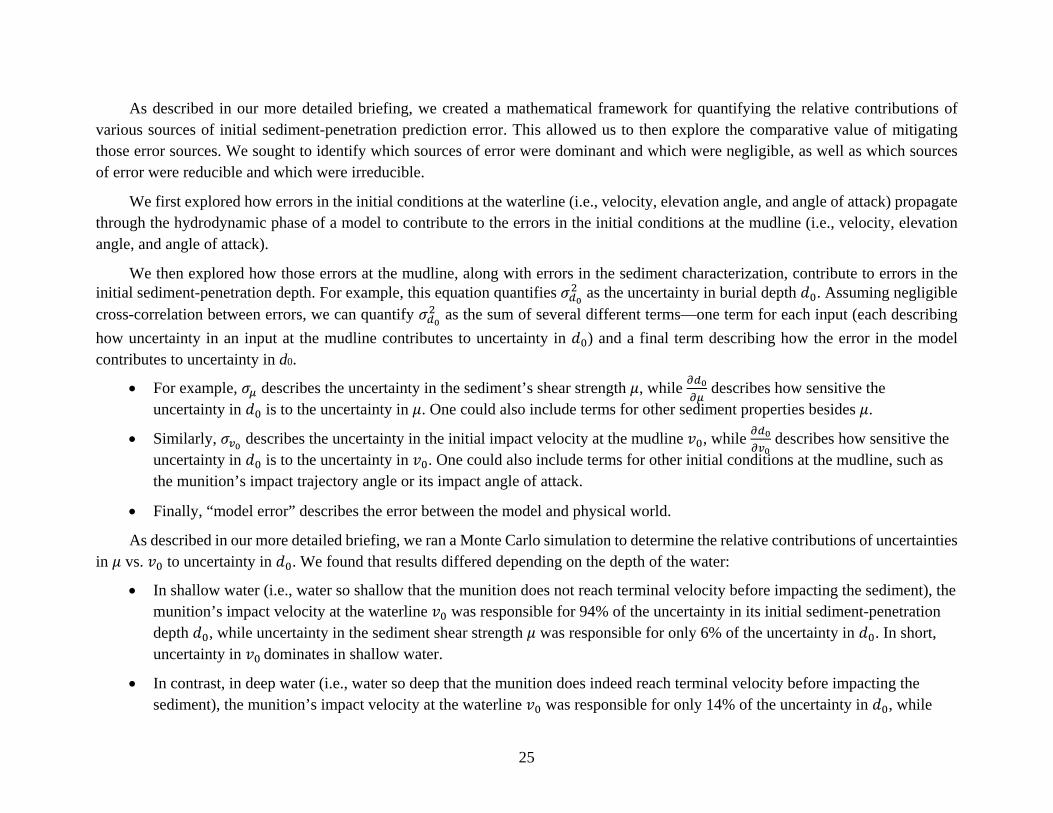
As described in our more detailed briefing, we created a mathematical framework for quantifying the relative contributions of various sources of initial sediment-penetration prediction error. This allowed us to then explore the comparative value of mitigating those error sources. We sought to identify which sources of error were dominant and which were negligible, as well as which sources of error were reducible and which were irreducible.
We first explored how errors in the initial conditions at the waterline (i.e., velocity, elevation angle, and angle of attack) propagate through the hydrodynamic phase of a model to contribute to the errors in the initial conditions at the mudline (i.e., velocity, elevation angle, and angle of attack).
We then explored how those errors at the mudline, along with errors in the sediment characterization, contribute to errors in the initial sediment-penetration depth. For example, this equation quantifies as the uncertainty in burial depth . Assuming negligible cross-correlation between errors, we can quantify as the sum of several different terms—one term for each input (each describing how uncertainty in an input at the mudline contributes to uncertainty in ) and a final term describing how the error in the model contributes to uncertainty in d0.
For example, describes the uncertainty in the sediment’s shear strength , while describes how sensitive the uncertainty in is to the uncertainty in . One could also include terms for other sediment properties besides .
Similarly, describes the uncertainty in the initial impact velocity at the mudline , while describes how sensitive the uncertainty in is to the uncertainty in . One could also include terms for other initial conditions at the mudline, such as the munition’s impact trajectory angle or its impact angle of attack.
Finally, “model error” describes the error between the model and physical world.
As described in our more detailed briefing, we ran a Monte Carlo simulation to determine the relative contributions of uncertaintiesin vs. to uncertainty in . We found that results differed depending on the depth of the water:
In shallow water (i.e., water so shallow that the munition does not reach terminal velocity before impacting the sediment), themunition’s impact velocity at the waterline was responsible for 94% of the uncertainty in its initial sediment-penetrationdepth , while uncertainty in the sediment shear strength was responsible for only 6% of the uncertainty in . In short,uncertainty in dominates in shallow water.
In contrast, in deep water (i.e., water so deep that the munition does indeed reach terminal velocity before impacting thesediment), the munition’s impact velocity at the waterline was responsible for only 14% of the uncertainty in , while

26
uncertainty in the sediment shear strength was responsible for 86% of the uncertainty in . In short, uncertainty in dominates in deep water.


28
Comparative sources of burial depth uncertainty
Use simplified models with sensitivity analytic framework to understand when and how initial sediment penetration predictions can be improved.
+ … + model error
Waterline
Mudline
= sediment shear strength
Sediment property uncertainty
Burial depth uncertainty
Burial model sensitivity
Uncertainty from hydrodynamic model
Hydrodynamic model error
Input uncertainty to hydrodynamic model
Uncertainty contributions: sediment phase
Data
Total square error contribution
Deep
(86%)
Shallow
(94%)
(6%) (14%)

29
Note that the results discussed here were found when a single model was used (i.e., when the “model error” term was held constant). However, the model error term is, in fact, reducible. That is, one could shrink this model error term by improving the sediment-penetration model so that it better simulates the physical world. However, improving the model would only really be useful if the model error term exceeded . One must therefore consider the value in improving the model (i.e., shrinking the model error term) versus shrinking the uncertainties in inputs to the model (e.g., shrinking and ).
Unfortunately, it is not possible to reduce the uncertainties in all inputs to the model:
represents the munition’s initial impact velocity at the mudline. This value is unknown. One could estimate this value isbased on a hydrodynamic model. Therefore, one could shrink by improving the hydrodynamic model used to estimate
—that is, one could shrink the hydrodynamic model error. However, remember that the hydrodynamic model takes ininputs about the munition’s impact at the waterline, immediately after firing. In many cases, this firing has already occurredin the past, sometime several decades ago. All records regarding the initial firing conditions may be lost, and all informationabout the sea state (e.g., water height) as the munition hit the waterline are unknown. Therefore, one cannot shrink furtherbecause one cannot shrink the uncertainties around the inputs to the hydrodynamic model. Thus, while one contribution to
is reducible (the hydrodynamic model error), other contributions to are irreducible (input uncertainty to thehydrodynamic model).
represents the sediment shear strength. If the uncertainty in stems from measurement error, then better measurementtechniques might shrink . On the other hand, if there is a point-to-point spatial variation in over the local region ofinterest, then it may not be possible to shrink . Thus, may be only partly reducible.
We therefore recommend using simplified models coupled with our mathematical framework to understand when and how initial sediment-penetration predictions can and should be improved.
Some further details can be found on our backup slide “Our Example: Unstable, Broadside Flop.”

30
WHERE WOULD ADDITIONALFIDELITY HELP?

31
We have now explored:
What fidelity (i.e., accuracy and precision) is useful for underwater UXO remediation projects when estimating a munition’sinitial penetration depth into the sediment.
What fidelity is already achievable via existing penetration models that have already been developed for underwater mines.
We will now consider our third and final question: Where (and when) would additional fidelity be helpful for underwater UXOremediation projects?

32
• Improving the model will not fully eliminateuncertainty in initial sediment penetration depth
due to irreducible uncertainty inenvironmental conditions ( ) and initial impactconditions at the waterline.
*Rennie and Brandt, “SERDP Project MR‐2227 Interim Report,” August 2015.
0 0.1 0.2 0.30
0.2
0.4
0.6
0.8
1Cumulative distribution of UXO burial depth in sand
burial depth, m
prob
abili
ty
Fraction of potentially mobile UXO at the time of impact
Mob
ility limit
Burial depth , m2
Connecting Useful Fidelity to Achievable Fidelity:Shallow Water Example

33
Consider, as an example, a particular case of munitions buried in sand in shallow water depths, 3–5 meters. In the upper right figure, we show the cumulative distribution of the buried depth, in this case based on the uncertainties in:
the waterline impact velocity (we assume a uniform distribution 50 to 300 m/s),
the waterline impact entrance angle (we assume a normal distribution with mean = /4 and standard deviation = /12) and,
the sediment shear strength (we assume normally distributed with mean = 20 MPa and standard deviation = 5 MPa).
As can be seen from the upper right figure, slightly more than 40% of munitions will have a sediment-penetration depth less than1/2 of the diameter D, making them potentially mobile. In other words, our simplified model predicts that there will be about 40% of the munitions will be initially mobile.
Note that the spread of the cumulative distribution in the upper right figure reflects the uncertainty in the waterline initial conditions and sediment shear strength and is therefore irreducible. We can overlay this irreducible uncertainty on the burial regime map developed in the first part of our analysis, as we show in the bottom left corner by a blue arrow. (The magnitude of is estimated from the cumulative distribution to be about 1.5 times the munition diameter D.) If the munition lands in an area where the underwater currents are not high enough to make the munition mobile, then the munition will remain stable. Improving the accuracy of the model (either in the hydrodynamic or sediment phases or in both) will not lead to improving our knowledge of the fate of this munition, given this large (irreducible) uncertainty in its initial sediment-penetration depth.

34
• Improving the model will not fully eliminateuncertainty in initial sediment penetration depth
due to irreducible uncertainty inenvironmental conditions ( ) and initial impactconditions at the waterline.
*Rennie and Brandt, “SERDP Project MR‐2227 Interim Report,” August 2015.
0 0.1 0.2 0.30
0.2
0.4
0.6
0.8
1Cumulative distribution of UXO burial depth in sand
burial depth, m
prob
abili
ty
Fraction of potentially mobile UXO at the time of impact
Mob
ility limit
Burial depth , m
ErosionMudline
Annual variation of sediment level*
2
Connecting Useful Fidelity to Achievable Fidelity:Shallow Water Example

35
Here we show the effect of sediment floor height variation on the munition burial depth. Consider, as an example, a particular case of munitions buried at a specific location: Duck, North Carolina. Shown on the upper left corner is Duck’s reported yearly variation of sediment depth as a function of distance from shore and water depth. In shallow depths (i.e., about 5 m), that variation is on the order of 0.2 m. We ask the following question: How will this variation in sediment level affect the uncertainty in burial depths of munitions?

36
• Improving the model will not fully eliminateuncertainty in initial sediment penetration depth
due to irreducible uncertainty inenvironmental conditions ( ) and initialconditions at the waterline.
• Sediment floor erosion/accretion will wipe outthe effect of uncertainty in initial penetrationdepth .
*Rennie and Brandt, “SERDP Project MR‐2227 Interim Report,” August 2015.
0 0.1 0.2 0.30
0.2
0.4
0.6
0.8
1Cumulative distribution of UXO burial depth in sand
burial depth, m
prob
abili
ty
New fraction of UXO potentially mobilized by erosion
Fraction of potentially mobile UXO at the time of impact
Mob
ility limit
Burial depth , m
ErosionMudline
Annual variation of sediment level*
2
Connecting Useful Fidelity to Achievable Fidelity:Shallow Water Example
0.2m

37
If the local bottom floor conditions are such that these munitions are initially immobile, the scour process and local sediment floor variation (i.e., accretion) may bury the munition, making the magnitude of initial sediment-penetration depth irrelevant. On the other hand, the sediment floor variation can also expose the munition and make it potentially mobile if it takes place on the timescale shorter than that of the scour process. For example, at about 5 m depth, a sediment level variation of 0.2 m may expose initially buried munitions and increase the portion of the potentially mobile munitions.
We represent the sediment-level variation uncertainty in the burial regime map by a red arrow. We observe that in addition to the uncertainty in initial burial depth there is also irreducible uncertainty in increasing (decreasing) the depth due to sediment floor variation. Improving modelling accuracy will unlikely be useful in this case.
This example demonstrates that under certain conditions the depth of the munition’s initial penetration into the sediment does not affect its subsequent exposure and mobility; in this case, an improvement in the accuracy of the munition’s initial penetration prediction does not lead to more accurate assessment of the munition’s fate.

38
• Improving the model will not fully eliminateuncertainty in initial sediment penetration depth
due to irreducible uncertainty inenvironmental conditions ( ) and initialconditions at the waterline.
• Sediment floor erosion/accretion will wipe outthe effect of uncertainty in initial penetrationdepth .
• The only risk bucket sensitive to model fidelity isinitial mobility.
*Rennie and Brandt, SERDP Project MR‐2227 Interim Report, August 2015.
0 0.1 0.2 0.30
0.2
0.4
0.6
0.8
1Cumulative distribution of UXO burial depth in sand
burial depth, m
prob
abili
ty
New fraction of UXO potentially mobilized by erosion
Fraction of potentially mobile UXO at the time of impact
Mob
ility limit
Burial depth , m
ErosionMudline
Annual variation of sediment level*
2
Connecting Useful Fidelity to Achievable Fidelity:Shallow Water Example
0.2m

39
The burial regime maps can help to answer the question: When will improvement in model accuracy be useful?
If the bottom water velocity is low and the munition remains immobile after the impact, then the scour processes andsediment floor depth variations will control the fate of the munition and erase the effect of the initial sediment-penetrationdepth, reducing the usefulness of the model fidelity improvements.
If, on the other hand, the bottom water velocity is such that the munition can be mobile, then the munition’s mobility isdetermined by its initial sediment-penetration depth, and the accuracy of the penetration predictions is very important,because it will influence the mobility and fate of the munition.
These considerations show that the usefulness of improving the modeling accuracy depends on the particular case of interest. In our example, accurately predicting the initial mobility of munitions may help estimating the fraction of potentially mobile munitions, even though there is considerable irreducible uncertainty in their initial sediment-penetration depths.

40
Summary of Recommendations
1. Improve sandy sediment penetration models.2. Develop mobility models for silt.3. Develop mobility models for partially buried objects.4. Develop scour burial model for silt.5. Improve models of consolidation and creep.6. Exercise caution in improving hydrodynamic models to support initial sediment penetration
estimates—the effect of better hydrodynamics may be dwarfed by stochasticity due tounknown precise initial conditions at the waterline.
7. Existing sediment penetration models (other than STRIKE35) are designed for near-cylindrical mines—for munitions, however, projectile-specific drag, lift, and momentcoefficients are needed for estimating hydrodynamic stability and gross velocity.
8. Modules of existing depth penetration models are nearly independent and could andshould be mixed and matched with little effort to choose best-of-breed for each regime(air/water/sediment).
9. Use simplified models with sensitivity analytic framework to understand when and howinitial sediment penetration predictions can be improved.
10. Use regime map to evaluate whether proposed improvements in fidelity will haveoperational utility.

41
We conclude with a summary of our recommendations. Please contact Shelley Cazares at [email protected], 703 845 6792, for the longer, more detailed version of this briefing.


43
Backups

44
Burial regime map: Sandy Sediment ExampleBroad side impactWater depth: uniform distribution, 3 to 5 mWater impact velocity: uniform distribution, 50 to 300 m/sWater impact angle: normal distribution, 45° 15°Sediment shear strength: normal distribution 20 kPa 5 kPa
Fraction of UXO
Potentially mobile UXO
0 2 4 6 8 100
0.1
0.2
0.3
0.4mobility lineequilibrium scour depthUXO diameter95% of UXO burial depth5% of UXO burial depth
buttom current velocity, m/s
initi
al b
uria
l dep
th, m
Uncertainty in penetration depth due to variation in water impact angle and velocity, water depth, and sediment shear strength
Initial pen
etratio
n depth,
(m)
Bottom water velocity, (m/s)
%
%
mobility thresholdequilibrium scour burial
D
/2
Return

45
A Quantitative Example of the Burial Regime Map The first question we asked in our analysis was: What fidelity (i.e., accuracy and precision) is useful for underwater UXO
remediation projects when estimating a munition’s initial penetration depth into the sediment?
To answer this question, we proposed the construction of a burial regime map of initial sediment-penetration depth vs. bottom water velocity. This map must be created for every scenario of interest.
This slide shows a quantitative example of constructing a burial regime map for a particular scenario.
Here, on the right, we show a quantitative instance of the mobility and scour burial portions of the regime map. We utilized the equilibrium scour burial depth model from Rennie and Brandt (2015) and the IDA mobility threshold model for 100 micron sand. On the left, we show a histogram of initial sediment-penetration depths from a Monte Carlo model discussed in the more detailed version of this briefing. The Monte Carlo simulation randomized over input values as described at the top of this slide. As shown, although the mean initial penetration depth is approximately half the munition diameter, the variability in the penetration depth in this case is large compared with the scale of the regions on the map. In this case, the benefit of predicting initial penetration depth to high fidelity for any given input conditions would be negated by the high variability in initial penetration depth due to input condition variation. In short, the useful fidelity of initial penetration prediction is bounded by the variability in uncontrolled and unknown initial conditions.

46
4P. Chu et al., “Modeling of Underwater Bomb Trajectory for Mine Clearance,” Journal of Defense Modeling and Simulation: Applications, Methodology, Technology 8( 1) (2001): 25–36.
3P. Chu and C. Fan, “Mine‐Impact Burial Model (IMPACT‐35) Verification and Improvement Using Sediment Bearing Factor Method,” IEEE J. of Ocean Eng. 32, no. 1 (January 2007 ).
1P. Chu, “Mine Impact Burial Prediction From One to Three Dimensions,” Applied Mechanics Review62 (January 2009).2J. Mann et al., “Deterministic and Stochastic Predictions of Motion Dynamics of Cylindrical Mines Falling Through Water,” IEEE Journal of Ocean Engineering32, no. 1 (2007).
Exercise caution improving hydrodynamic models. Effect of better hydrodynamics may be dwarfed by stochasticity due to unknown precise initial conditions at the waterline.
Brief Description of the ModelsModel Name Description Validation
2-D models predict rigid body motion in the x–z plane including rotation about the y-axis
IMPACT25/28 3 DOF model from air-drop through water column.1• Hydro: Developed to address rotation (absent in 1-D predecessor IBPM).• Sediment: Handles multi-layers
Limited low velocity mine drops (<10m/s)
3-D models predict rigid body motion in x,y,z coordinates including rotation about the x,y,z axes.All have been compared favorably to limited experimental results
MINE6-D(Hydrodynamic only)
6-DOF model2 designed to accurately capture complex 3-D dynamics of minesin the water column.
Limited low velocity mine drops (<10m/s)
IMPACT35 5-DOF model3 (neglects rotation about the axis of symmetry) for near-cylindrical mines.• Hydro: Designed to account for y-direction currents and observed 3-D
dynamic modes of falling mines.• Sediment: Adds new rate-dependent sediment strength model to
IMPACT25/28.
Limited low velocity mine drops (<10m/s)
STRIKE35(Hydrodynamic only)
6-DOF model describes motion of JDAM through a water column.4Designed to model high-velocity hydrodynamic behavior of a tapered objectwith fins.
Several high velocity JDAM drops (400m/s)
Models and experiments show high sensitivity to initial conditions at waterline.

47
The second question we asked in our analysis was: What fidelity is already achievable via existing penetration models that have already been developed for underwater mines?
We reviewed four different models:
IBPM, the Interim Burial Prediction Model, was a one-dimensional model that assumed a constant mine orientation. IBPM was expanded into a two-dimensional model capturing three degrees of freedom (two directions in position and one orientation, all in a single two-dimensional plane). That model was implemented in BASIC as IMPACT25 and in MATLAB as IMPACT28. The IMPACT25/28 model addresses all three phases of descent (aerodynamic, hydrodynamic, and sediment) and accommodates multiple sediment layers with different properties. IMPACT25/28 utilizes a simplified sediment-penetration model based on bearing strength and assuming a simple relationship between bearing strength and shear strength. IMPACT25/28 also incorporates inertial resistance of the sediment, which may not be of critical importance in low-velocity mine sediment impacts but could be essential in high-velocity munition projectile impacts. IMPACT25/28 includes a cavitation model capturing such aspects as cavity oscillation frequency. Although capturing a lot of cavitation detail, the model requires empirical determination of a number of coefficients.
IMPACT35 was then developed to incorporate more complex three-dimensional observed hydrodynamic behavior in descending mines, such as helical motion. A third dimension is also required to account for water currents in directions other than in plane with the falling projectile. IMPACT35 is a five-degree-of-freedom model incorporating three directions of translation and two of rotation (pitch and yaw, but not roll, which is assumed to be immaterial due to rotation symmetry of the mines under consideration). IMPACT35 implemented what is known as the delta method for sediment-penetration estimation, which incorporates the effect of pore pressure. Further analysis and experiments with low-velocity mine drops suggested a better sediment-penetration model known as the bearing factor method, which was incorporated into IMPACT35 in lieu of the delta method.
MINE6D was developed for the same reasons as IMPACT35: to accurately capture the complex three-dimensional dynamics of sinking mines. MINE6D adds the sixth degree of freedom of roll and can accommodate rotationally asymmetric shapes. MINE6D attempts to more rigorously capture the hydrodynamic interaction of the water with the sinking mine.
All three of the preceding models were supported by limited validation experiments with low-velocity mine drops. In mine drop experiments, the mines entered the water gently or were dropped from a low elevation. They typically, therefore, entered the water below hydrodynamic terminal velocity and accelerated as they descended. Contrast that with the UXO problem in which munition

48
projectiles enter the water at velocities far in excess of the hydrodynamic terminal velocity and decelerate as they descend. Terminal velocity is the velocity that is asymptotically approached (from above or below) at which the hydrodynamic (or aerodynamic) resistance forces exactly balance buoyancy and gravity to produce zero acceleration. Therefore:
STRIKE35 was produced to capture the behavior of the high-velocity projectiles. It was developed and validated inconjunction with a set of experiments dropping Joint Direct Attack Munition (JDAM) bombs into an instrumented pond. TheJDAMs entered the water at roughly 400 m/s. STRIKE35 utilizes simple forward Euler time-discretization to model progressthrough the water. Where STRIKE35 differs most from the other models is in its use of projectile-specific semi-empiricalexpressions for hydrodynamic lift, drag, and moment coefficients accommodating specifics such as fin geometry. Any of themodels could be enhanced with experimentally derived hydrodynamic coefficients at the velocity ranges of interest.STRIKE35 takes as its initial conditions the entry velocity into the water and does not incorporate sediment penetration.STRIKE35 takes an ad hoc approach to cavitation by assuming that cavitation reduces the drag by a factor of 10 and thensuddenly ceases when the munition angle of attack exceeds a pre-specified value.
These four models may do an excellent job predicting the progress of a projectile through the water given initial conditions. For the munition projectiles of interest in underwater UXO remediation, however, the initial conditions at the waterline may be highly uncertain. Therefore, adding fidelity to the hydrodynamic model may not address the dominant source of uncertainty in the sediment-penetration prediction. In addition, the details of the projectile’s progress through the water column may not have a strong influence on its initial conditions at the mudline and may therefore not strongly influence its penetration depth. Experiments and models have exhibited strong sensitivity to initial conditions. In experiments with nominally similar mine release conditions, different falling modalities (e.g., see-saw vs. helical spiral) have been observed, suggesting instabilities not conducive to modeling. The statistics of the mudline impact velocity are more important than identifying which precise initial conditions lead to each descent modality.
Ultimately, caution should be exercised before investing further in high-fidelity hydrodynamic models as the goal is to characterize sediment-penetration depth.


50
Return
Model Features
Dimen
sions
DOF
Aerodyna
mic
Wind
Waterline
interface
Hydrodyna
mic
Cavitatio
n
Fins
Current
Mud
line
interface
Sedimen
t
Inertia
l drag
IMPACT 25/28 2 3 Y N Y Y Y N N Y Y Y
IMPACT 35 3 5 Y Y Y Y N N Y Y Y N
STRIKE 35 3 6 N Y Y Y Y N N N
MINE 6D 3 6 N Y Y Y N Y N N
Models (other than STRIKE35) are designed for near‐cylindrical mines. For UXO, projectile‐specific drag, lift, and moment coefficients are needed for estimating
hydrodynamic stability and gross velocity.
Model modules (aero, hydro, sediment) are nearly independent and could and should be mixed and matched with little effort to choose best‐of‐breed for each regime (aero, hydro,
sediment) for each scenario of interest.

51
Here we show a tabular breakdown of the features captured by the various models.
Even though STRIKE35 is the only model to use highly specific empirical hydrodynamic coefficients, it would not be difficult to implement this type of characteristic in any of the hydrodynamic models. The hard work is gathering the empirical data on each class of projectile. If models other than STRIKE35 are used, the existing hydrodynamic coefficients based on cylindrical mines would likely not adequately capture the hydrodynamic behavior of munition projectiles for good sediment-penetration prediction. In particular, the models ought to capture the hydrodynamic stability of the projectiles, because projectiles penetrating the water column in a stable fashion will exhibit much higher terminal velocities and higher sediment impact velocities than mines do.
Also of note, the models incorporating multiple phases of descent (aerodynamic, hydrodynamic, and sediment) splice them together in a relatively compartmentalized fashion, allowing the mixing and matching of modules between models with relative ease. In fact, NRL Stennis used several models in tandem to construct a prototype probabilistic framework to statistically categorize spatial distribution of expected initial munitions contamination (Holland 2015).

52
Total square error contribution
DeepShallow
Our Example: Unstable, Broadside Flop
42
Operating Point and Initial Condition UncertaintyCases
m/s m/s
Shallow 25 27 56° 13° 50°0 50%*
Deep 4.9 0.5 70° 0.7° 90°Contribution to Initial Burial Depth Uncertainty TotalShallow 216% 15% 0
50%222%
Deep 20% 0% 0 54%
For the Unstable, Broadside Flop case:
• In shallow water: Uncertainty in dominates the uncertainty in
• In deep water: Uncertainty in dominates the uncertainty in
e.g., 27 m/s error in leads to a 216% error in
*Rennie and Brandt, “SERDP Project MR‐2227 Interim Report,” August 2015.

53
The second question we asked in our analysis was: What fidelity is already achievable via existing penetration models that have already been developed for underwater mines?
As described in our more detailed briefing, we created a mathematical framework for quantifying the relative contributions of various sources of initial sediment-penetration prediction error. This allowed us to then explore the comparative value of mitigating those error sources. We sought to identify which sources of error were dominant and which were negligible, as well as which sources of error were reducible and which were irreducible.
We explored how uncertainty in the initial conditions at the mudline (i.e., velocity v0, elevation angle 0, and angle of attack 0) contribute to the uncertainty in the estimate of sediment-penetration depth d0.
Using results from our Monte Carlo simulation and from the scientific literature to evaluate the operating points and the variance of the mudline initial conditions (only the contribution from initial waterline condition variation), we exercise our mathematical framework and compared the error contributions:
In shallow water, the waterline projectile velocity significantly influences the mudline projectile velocity, so variation in sediment impact velocity is not erased by depth. Uncertainty in the projectile velocity at the mudline then dominates the uncertainty in the sediment-penetration depth. Improving the sediment-penetration model would only help if the fractional sediment model error / exceeds 100%. Since the velocity uncertainty considered here stems from projectile firing condition variation, it is irreducible. Additional improvements in measurement or modeling will only be useful if their current contribution exceeds a 100% fractional error.
In deep water, where the effect of the irreducible uncertainties of the firing conditions are effaced by the achievement of terminal velocity, uncertainty in the sediment properties dominates the overall sediment-penetration prediction uncertainty. If the uncertainty in sediment properties stems from measurement error, better measurement techniques might improve sediment-penetration prediction accuracy. On the other hand, if it is dominated by point-to-point spatial variation in the sediment properties over the local region of interest, it will be irreducible, and further model or measurement enhancements will do little to improve the accuracy of sediment-penetration prediction.


A-1
References
Holland, K. Todd. 2015. “A Wide Area Risk Assessment Framework for Underwater Military Munitions Response.” MR 2411. Naval Research Laboratory – Stennis Space Center In-Progress Review Meeting, May 20.
Rennie, Sarah, and Alan Brandt. 2015. “Interim Report: Underwater Munitions Expert System to Predict Mobility and Burial, SERDP Project MR-2227.” Laurel, MD: Johns Hopkins University, Applied Physics Laboratory. https://www.serdp-estcp.org/content/download/36174/345934/file/MR-2227-IR.pdf.


REPORT DOCUMENTATION PAGE Form Approved
OMB No. 0704-0188 The public reporting burden for this collection of information is estimated to average 1 hour per response, including the time for reviewing instructions, searching existing data sources, gathering and maintaining the data needed, and completing and reviewing the collection of information. Send comments regarding this burden estimate or any other aspect of this collection of information, including suggestions for reducing the burden, to Department of Defense, Washington Headquarters Services, Directorate for Information Operations and Reports (0704-0188), 1215 Jefferson Davis Highway, Suite 1204, Arlington, VA 22202-4302. Respondents should be aware that notwithstanding any other provision of law, no person shall be subject to any penalty for failing to comply with a collection of information if it does not display a currently valid OMB control number. PLEASE DO NOT RETURN YOUR FORM TO THE ABOVE ADDRESS. 1. REPORT DATE
July 2017 2. REPORT TYPE
Final 3. DATES COVERED (From–To)
Jun 2017 – Jul 20174. TITLE AND SUBTITLE
UXO Burial Prediction Fidelity: A Summary
5a. CONTRACT NUMBER HQ0034-14-D-0001
5b. GRANT NUMBER
5c. PROGRAM ELEMENT NUMBER
6. AUTHOR(S)
Teichman, Jeremy A.Macheret, Yevgeny Cazares, Shelley M.
5d. PROJECT NUMBER AM-2-1528
5e. TASK NUMBER
5f. WORK UNIT NUMBER
7. PERFORMING ORGANIZATION NAME(S) AND ADDRESS(ES)
Institute for Defense Analyses4850 Mark Center Drive Alexandria, VA 22311-1882
8. PERFORMING ORGANIZATION REPORTNUMBER
IDA Document NS D-8617
9. SPONSORING / MONITORING AGENCY NAME(S) ANDADDRESS(ES)
Director and Program Manager for MunitionsSERDP/ESTCP 4800 Mark Center Drive Suite 17D08 Alexandria, VA 22350-3605
10. SPONSOR/MONITOR’S ACRONYM(S)
SERDP/ESTCP
11. SPONSOR/MONITOR’S REPORTNUMBER(S)
12. DISTRIBUTION/AVAILABILITY STATEMENT
Approved for public release; distribution is unlimited (3 November 2017).
13. SUPPLEMENTARY NOTES
14. ABSTRACTThe Institute for Defense Analyses (IDA) is a not-for-profit company that operates three Federal Funded Research andDevelopment Centers (FFRDCs). We perform scientific and technical analyses for the US government on issues related tonational security. Recently, we performed a numerical analysis for the Strategic Environmental Research and DevelopmentProgram (SERDP) to explore the fidelity of computational models for predicting the initial penetration depth of UnexplodedOrdnance (UXO) in underwater sites. This briefing provides a summary of our analysis. A separate, longer briefing describesthe details of our analysis.
15. SUBJECT TERMS
accretion, erosion, IMPACT25, IMPACT28, IMPACT35, MINE6-D, scour, sensitivity analysis, STRIKE35, Unexploded Ordnance, UXO 16. SECURITY CLASSIFICATION OF: 17. LIMITATION
OF ABSTRACT
UU
18. NUMBER OF
PAGES
55
19a. NAME OF RESPONSIBLE PERSON Nelson, Herbert
a. REPORTUncl.
b. ABSTRACTUncl.
c. THIS PAGEUncl.
19b. TELEPHONE NUMBER (include area code)
571-372-6400Standard Form 298 (Rev. 8-98) Prescribed by ANSI Std. Z39.18