(v-300) mach 1 iom - crp 1 iom.pdf · flow control division mach 1™ section 1.0 high performance...
TRANSCRIPT
Flow Control Division
Section 1.0
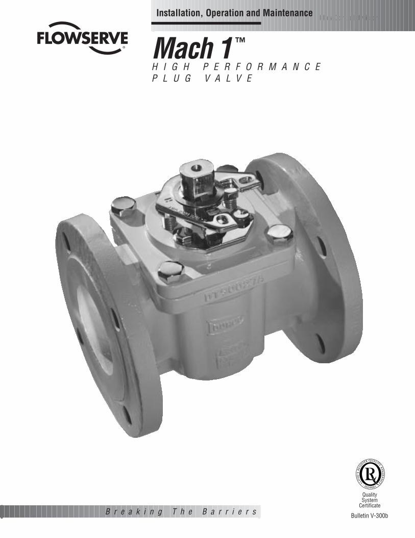
Mach 1 ™
H I G H P E R F O R M A N C E P L U G V A L V E
B r e a k i n g T h e B a r r i e r s
Quality System
Certificate
Bulletin V-300b
Installation, Operation and Maintenance
(V-300) Mach 1 IOM 12/5/02 11:22 AM Page 2 Dan K. Snelson Clients:019-FLOWSERVE Valves:019-Job Files:019-Closed Jobs:

FLANGED:Installation of Flowserve flanged valves is best accomplished bylocating valves in pipeline flanges, assuring all corrosion andforeign materials are removed from pipe flanges and then centergaskets with the valve flanges. Fasteners or taper pins shouldbe used to align holes and locate gaskets. Fasteners should betightened to the corresponding valve and fastener size.
2
Flow Control Division
Section 1.0
SECTION I
INSTALLATION INSTRUCTIONS - FLANGED MACH 1, CLASS 150, 300 AND 600
TABLE I-1 Temperature Limitations
Material Description Maximum Service TemperaturePFA 525°F (274°C)
TABLE OF CONTENTSSECTION TITLE PAGEI INSTALLATION. . . . . . . . . . . . . . . . . . . . . . . . . . . . . . . . . . . . . . . . . . . . . . . . . . . . . . . . . . . . . . . . . . . . . . . . . . . . . . . . . 2
II OPERATING/MAINTENANCE INSTRUCTIONS FOR MACH 1. . . . . . . . . . . . . . . . . . . . . . . . . . . . . . . . . . . . . . . . . . . . . . . 3
III VALVE DISASSEMBLY - MACH 1
RECOMMENDED PRECAUTIONARY MEASURES . . . . . . . . . . . . . . . . . . . . . . . . . . . . . . . . . . . . . . . . . . . . . . . . . . . . . . . 4
DISASSEMBLY STEPS . . . . . . . . . . . . . . . . . . . . . . . . . . . . . . . . . . . . . . . . . . . . . . . . . . . . . . . . . . . . . . . . . . . . . . . . . . . 4
IV PRESSURE CONTAINING FASTENERS. . . . . . . . . . . . . . . . . . . . . . . . . . . . . . . . . . . . . . . . . . . . . . . . . . . . . . . . . . . . . . . 5
V A. VALVE ASSEMBLY 1"-6" MACH 1 WITH PORT SEALS . . . . . . . . . . . . . . . . . . . . . . . . . . . . . . . . . . . . . . . . . . . . . . . . . 6
B. VALVE ASSEMBLY 1"-6" MACH 1 WITH SLEEVE . . . . . . . . . . . . . . . . . . . . . . . . . . . . . . . . . . . . . . . . . . . . . . . . . . . . . 9
VI ASSEMBLY SPECIFICATIONS - FIRESEAL VALVES 1"-6" MACH 1 . . . . . . . . . . . . . . . . . . . . . . . . . . . . . . . . . . . . . . . . . 10
(V-300) Mach 1 IOM 12/5/02 11:22 AM Page 3 Dan K. Snelson Clients:019-FLOWSERVE Valves:019-Job Files:019-Closed Jobs:

3
Flow Control Division
Section 1.0
FIGURE II-1Typical Assembly of Mach 1
SECTION II
OPERATING/MAINTENANCE INSTRUCTIONS FOR MACH 1
Maintenance requirements for Mach 1 valves may vary due tooperating conditions of the process. Factors such as operatingtemperature, pressure, solids content, and frequency of cyclingcan influence valve performance and maintenance requirements.
Seal wear is compensated by adjusting appropriate parts. ForMach 1 valves, there are three possible leak paths:1. Top Cap (bonnet)2. Stem3. Line (through)
Corresponding adjustments for each leak path are as follows.NOTE: Refer to Figure II-1 or Figure VI-1 for parts identification
1. Top Cap (bonnet)Leakage due to thermal or pressure cycling is eliminated bytightening the top cap fasteners (Part 10) in a “criss-cross”pattern to the torque values given in the tables. This adjust-ment is most effective when the valve is not pressurized. Itis important that the top cap fasteners not be tightenedexcessively and that torque values applied be within industrystandard for fasteners.
2. Stem Leakage due to wear of the diaphragm, and/or wear to thesleeve (primary seal) is eliminated by tightening the adjusterfasteners (Part 11) in 1/4 turn increments. The adjusterfasteners must be tightened evenly for maximum adjust-ment. The valve should be operated between adjustments toassure that the plug properly seats itself into the sleeve. Ifleakage persists after repeated adjustments, the sleeve anddiaphragm will require replacement as covered in Section Vand Section VI.
3. Line (through)Through leakage due to wear of the primary seal can beeliminated by tightening the adjuster fasteners (Part 11) in1/4 turn increments. The fasteners must be tightened evenlyfor maximum adjustment. The valve should be operatedduring adjustments to prevent excessive operating torque.Should leakage persist after repeated adjustments, the portseals or sleeve will require replacement as covered inSection V and Section VI.
To avoid personal injury and prevent damage to equipment, donot operate or repair this valve without observing the followingprocedures outlined in this manual.
WARNING
16
14
12
10
9
8
7
6
5
43
2
1
11
13
15
(V-300) Mach 1 IOM 12/5/02 11:22 AM Page 4 Dan K. Snelson Clients:019-FLOWSERVE Valves:019-Job Files:019-Closed Jobs:
11. Inspect the valve port seals or sleeve for wear or damage,especially scratches near the top, bottom, and port areas. Ifwear or damage is excessive, the port seals/sleeve shouldbe replaced.
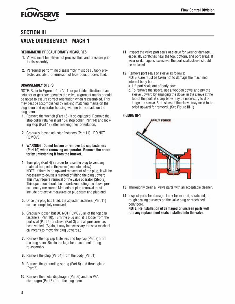
12. Remove port seals or sleeve as follows:NOTE: Care must be taken not to damage the machinedinternal body bore.a. Lift port seals out of body bowl.b. To remove the sleeve, use a wooden dowel and pry the
sleeve upward by engaging the dowel in the sleeve at thetop of the port. A sharp blow may be necessary to dis-lodge the sleeve. Both sides of the sleeve may need to bepried upward for removal. (See Figure III-1)
FIGURE III-1
13. Thoroughly clean all valve parts with an acceptable cleaner.
14. Inspect parts for damage. Look for marred, scratched, orrough sealing surfaces on the valve plug or machinedbody bore.NOTE: Reinstallation of damaged or unclean parts willruin any replacement seals installed into the valve.
4
Flow Control Division
Section 1.0
RECOMMEND PRECAUTIONARY MEASURES1. Valves must be relieved of process fluid and pressure prior
to disassembly.
2. Personnel performing disassembly must be suitably pro-tected and alert for emission of hazardous process fluid.
DISASSEMBLY STEPSNOTE: Refer to Figure II-1 or VI-1 for parts identification. If anactuator or gearbox operates the valve, alignment marks shouldbe noted to assure correct orientation when reassembled. Thismay best be accomplished by making matching marks on theplug stem and operator housing with no burrs made on theplug stem.1. Remove the wrench (Part 16), if so equipped. Remove the
stop collar retainer (Part 15), stop collar (Part 14) and lock-ing stop (Part 12) after marking their orientation.
2. Gradually loosen adjuster fasteners (Part 11) - DO NOTREMOVE.
3. WARNING: Do not loosen or remove top cap fasteners (Part 10) when removing an operator. Remove the opera-tor by unfastening it from the bracket.
4. Turn plug (Part 4) in order to raise the plug to vent anymaterial trapped in the valve (see note below).NOTE: If there is no upward movement of the plug, it will benecessary to devise a method of lifting the plug upward.This may require removal of the valve operator (Step 3).This operation should be undertaken noting the above pre-cautionary measures. Methods of plug removal mustinclude protective measures on plug stem and plug end.
5. Once the plug has lifted, the adjuster fasteners (Part 11)can be completely removed.
6. Gradually loosen but DO NOT REMOVE all of the top capfasteners (Part 10). Turn the plug until it is loose from theport seal (Part 2) or sleeve (Part 3) and all pressure hasbeen vented. (Again, it may be necessary to use a mechani-cal means to move the plug upwards.)
7. Remove the top cap fasteners and top cap (Part 9) fromthe plug stem. Retain the tags for attachment during re-assembly.
8. Remove the plug (Part 4) from the body (Part 1).
9. Remove the grounding spring (Part 8) and thrust gland(Part 7).
10. Remove the metal diaphragm (Part 6) and the PFAdiaphragm (Part 5) from the plug stem.
SECTION III
VALVE DISASSEMBLY - MACH 1
(V-300) Mach 1 IOM 12/5/02 11:22 AM Page 5 Dan K. Snelson Clients:019-FLOWSERVE Valves:019-Job Files:019-Closed Jobs:

SECTION IV
PRESSURE CONTAINING FASTENERS
MATERIAL SELECTIONSelecting the proper fastener material is the ultimate responsi-bility of the customer because the supplier does not typicallyknow in what service the valves will be used or what elementsmay be present in the environment. Flowserve normally sup-plies B7 (carbon steel) for ductile cast iron and carbon steelvalves. For stainless steel and high alloy valves, B8, Class 2B(stainless steel) fasteners are supplied as standard. All fasten-ers used must have a minimum yield strength of 65,000 PSI, aminimum elongation of 25% and be compatible with theprocess fluid. Determining compatibility to the process fluidgoes beyond a material being resistant to general corrosion because the more important consideration is a material’s resis-tance to stress corrosion cracking. Depending on the service, itmay make sense to use B7 fasteners on high alloy valves. Onesuch service would be marine environments because of stain-less steel’s susceptibility to stress corrosion cracking in chlo-ride environments. Another key aspect of fasteners is frequentvisual inspection. Because of the common practice of usingsteel fasteners rather than stainless steel to avoid chloridestress corrosion cracking, visual inspection is recommended to monitor the general corrosion of these fasteners. If jacketingor insulation is used on a valve, it must be periodically removed
for visual inspection of the fasteners. If you wish assistance indetermining the proper fasteners to use, please refer to theattached chart.
DESIGN & TYPEFlowserve’s valve design standards adopt ASME B18.2.1 (1996,Addenda 1999) as the standard for fastener type and design.This national standards requires that finished hex ‘head’ capscrews be used when the head of the fastener is turned. A fin-ished hex ‘head’ cap screw and a heavy hex cap screw have abearing surface under the head to minimize frictional resistanceduring tightening. They also comply to qualified body diametersand fully formed head dimensions. Cookeville Valve Operation’spolicy is to use finished hex ‘head’ and heavy hex ‘head’ capscrews for all pressure retaining fasteners. This includes topcaps, packing adjusters, plug adjusters, bottom caps, bodyhalves or other pressure retaining components. Complianceis made with ANSI B18.2.2 (1987, reaffirmed 1993), Squareand Hex Nuts, when studs and heavy hex nuts are required.Additional information on these items may be obtained from theFlowserve Corporation, Cookeville Valve Operation, Cookeville, Tennessee.
5
Flow Control Division
Section 1.0
TABLE ICAP SCREWS - STUDSHHCS - Finished Heavy Hex Head Cap Screw Alloy identification stamp required on each piece.HCS - Finished Hex Head Cap Screw Certification required.STUD - Stud Alloy Specification (40 KSI Minimum Yield Strength, 12% Minimum Elongation)Dimensions per ASME B18.2.1
B9 - Stainless Steel per ASTM A193, Class 2B, Grade B8 (AISI type 304)B16 Stainless Steel per ASTM A193, 100% hardness testedB7 - Chromium - Molybdenum Alloy Steel per ASTM A193, Grade B7B7M - Chromium - Molybdenum Alloy Steel per ASTM A193, Grade B7M, 100% hardness testedB7MT - Chromium - Molybdenum Alloy Steel per ASTM A193, Grade B7M, 100% hardness tested, Teflon® coated, Dupont SP11C,
Type B - Color blue or greenB8M - 316 Stainless Steel per ASTM A193, Grade B8M, Class 1, 40 KSI Min. Yield Strength, 12% Min. El.B8C2 - 304 Stainless Steel per ASTM A193, Grade B8, Class 2C20 - Carpenter C20, CB-3 (UNS NO8020), ASTM B473, 40 KSI Min. Yield Strength, 12% Min. ElHC - Hastelloy C276 (UNS N10276), ASTM B574I625 - Inconel 625 (UNS N006625), ASTM B446I825 Incoloy 825 (UNS N08825), ASTM B425, 40 KSI Min. Yield Strength, 12% Min. El.IN - Inconel 600 (UNS N0660), ASTM B166, 40 KSI Min. Yield Strength, 12% Min. El.M - Monel (UNS N04400), ASTM B164, Class A or B, 40 KSI Min. Yield Strength, 12% Min. El.HB - Hastelloy B (UNS 10665), ASTM B335I718 - Incoloy 718, AMS 5595B MKH - Monel K-500, Cold drawn and aged hardened, QQN-286 and ASTM F468L7 - Chromium-Molybdenum Alloy Steel per ASTM A320, Grade L7L7M - Chromium-Molybdenum Alloy Steel per ASTM A320, Grade L7M, 100% hardness testedL7T - Chromium-Molybdenum Alloy Steel per ASTM A320, Grade L7, Teflon® coated, Dupont SP11C, Type B - Color blue or greenL7MT - Chromium-Molybdenum Alloy Steel per ASTM A320, Grade L7M, 100% hardness tested, Teflon® coated, Dupont SP11C,
Type B - Color blue or greenN - Nickel per ASTM B160 (UNS N0220), 40 KSI Min. Yield Strength, 12% Min. El.B7YC - Chromium-Molybdenum Alloy Steel per A193, Grade B7, Yellow Zinc Dichromate Plated
(V-300) Mach 1 IOM 12/5/02 11:22 AM Page 6 Dan K. Snelson Clients:019-FLOWSERVE Valves:019-Job Files:019-Closed Jobs:
SECTION IV
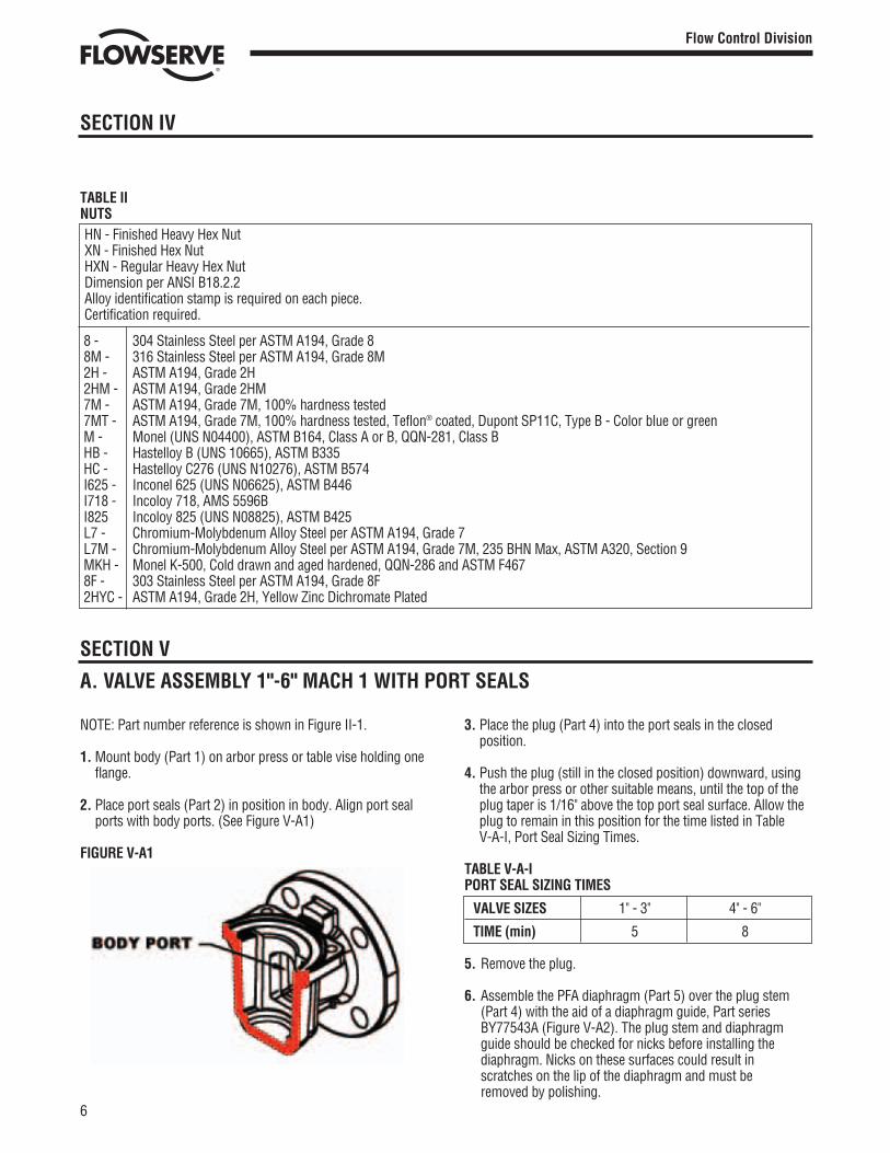
TABLE IINUTSHN - Finished Heavy Hex NutXN - Finished Hex NutHXN - Regular Heavy Hex NutDimension per ANSI B18.2.2Alloy identification stamp is required on each piece.Certification required.
8 - 304 Stainless Steel per ASTM A194, Grade 88M - 316 Stainless Steel per ASTM A194, Grade 8M2H - ASTM A194, Grade 2H2HM - ASTM A194, Grade 2HM7M - ASTM A194, Grade 7M, 100% hardness tested7MT - ASTM A194, Grade 7M, 100% hardness tested, Teflon® coated, Dupont SP11C, Type B - Color blue or greenM - Monel (UNS N04400), ASTM B164, Class A or B, QQN-281, Class BHB - Hastelloy B (UNS 10665), ASTM B335HC - Hastelloy C276 (UNS N10276), ASTM B574I625 - Inconel 625 (UNS N06625), ASTM B446I718 - Incoloy 718, AMS 5596BI825 Incoloy 825 (UNS N08825), ASTM B425L7 - Chromium-Molybdenum Alloy Steel per ASTM A194, Grade 7L7M - Chromium-Molybdenum Alloy Steel per ASTM A194, Grade 7M, 235 BHN Max, ASTM A320, Section 9MKH - Monel K-500, Cold drawn and aged hardened, QQN-286 and ASTM F4678F - 303 Stainless Steel per ASTM A194, Grade 8F2HYC - ASTM A194, Grade 2H, Yellow Zinc Dichromate Plated
6
Flow Control Division
Section 1.0
SECTION V
A. VALVE ASSEMBLY 1"-6" MACH 1 WITH PORT SEALS
NOTE: Part number reference is shown in Figure II-1.
1. Mount body (Part 1) on arbor press or table vise holding oneflange.
2. Place port seals (Part 2) in position in body. Align port sealports with body ports. (See Figure V-A1)
FIGURE V-A1
3. Place the plug (Part 4) into the port seals in the closedposition.
4. Push the plug (still in the closed position) downward, usingthe arbor press or other suitable means, until the top of theplug taper is 1/16" above the top port seal surface. Allow theplug to remain in this position for the time listed in TableV-A-I, Port Seal Sizing Times.
TABLE V-A-IPORT SEAL SIZING TIMES
VALVE SIZES 1" - 3" 4" - 6"
TIME (min) 5 8
5. Remove the plug.
6. Assemble the PFA diaphragm (Part 5) over the plug stem(Part 4) with the aid of a diaphragm guide, Part seriesBY77543A (Figure V-A2). The plug stem and diaphragmguide should be checked for nicks before installing thediaphragm. Nicks on these surfaces could result inscratches on the lip of the diaphragm and must beremoved by polishing.
(V-300) Mach 1 IOM 12/5/02 11:22 AM Page 7 Dan K. Snelson Clients:019-FLOWSERVE Valves:019-Job Files:019-Closed Jobs:

FIGURE V-A2
7. Place the metal diaphragm (Part 6) over the plug stem withthe raised center section up.
8. Place the thrust gland (Part 7) over the plug stem.
9. Apply a thin film of lubricant to the plug and place theassembled plug (complete with PFA diaphragm, metaldiaphragm and thrust gland), in the open position into thebody. (Figure V-A3).
FIGURE V-A3
10. Lay the top cap (Part 9) upside down (the bonnet gasketflange upward). Hold the grounding spring (Part 8) so thetabs on the spring ID point downward. Insert the groundingspring into the top cap and push the grounding spring tothe bottom of the center cavity in the top cap. (Figure V-A4).
FIGURE V-A4
11. Turn the top cap to the right side up position and place the
7
Flow Control Division
Section 1.0
SECTION V
top cap (with grounding spring in place) over the plugstem. Orient the top cap anti-rotation lugs with the anti-rotation lugs on the body (Figure V-A5).
FIGURE V-A5
12. Coat the top cap fastener threads (Part10) with Loctite® 242.Replace the tags removed in step 7 of Section III, ValveDisassembly. Install the top cap fasteners in the top cap.
13. Use an arbor press to push the top of the plug downwarduntil the bottom of the plug port aligns with the bottom ofthe body port.
14. Maintain the top cap position relative to the body anti-rota-tion lugs (Figure V-A5), and using all top cap fasteners(Part 10), tighten evenly in a cross-cross method until thetop cap bottoms on the body counterbore. (Figure V-A5).Tighten top cap fasteners to the value per valve size andpressure class as listed in Tables V-A-II, V-A-III and V-A-IV.
15. Remove the valve from the arbor press. Operate the plugseveral times. Torque will be high, but will reduce and theplug will turn freely.
16. Install adjuster fasteners (Part 11) (Figure V-A6) and handtighten evenly to the values listed in Table V-A-V or until thebottom of the plug port is 1/16" to 1/8" above the bottom ofthe body port.
FIGURE V-A6
(V-300) Mach 1 IOM 12/5/02 11:23 AM Page 8 Dan K. Snelson Clients:019-FLOWSERVE Valves:019-Job Files:019-Closed Jobs:
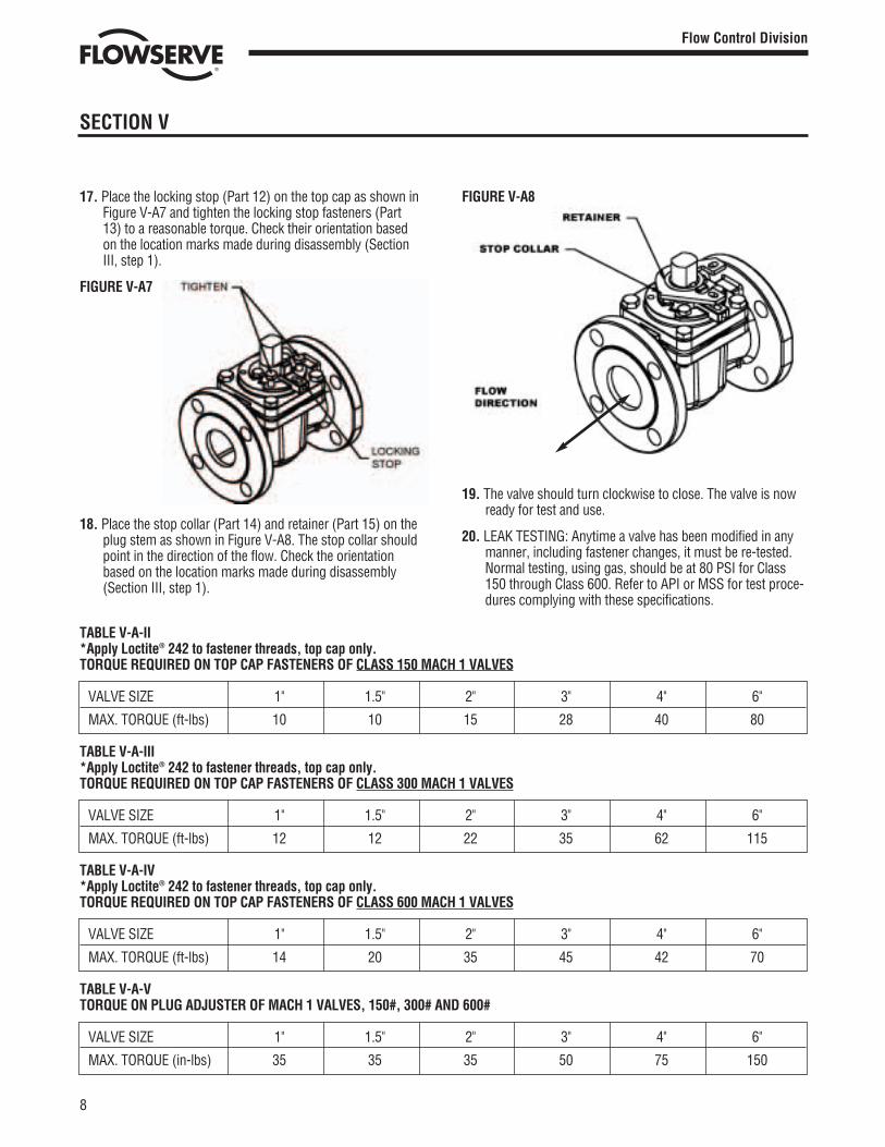
TABLE V-A-II *Apply Loctite® 242 to fastener threads, top cap only. TORQUE REQUIRED ON TOP CAP FASTENERS OF CLASS 150 MACH 1 VALVES
VALVE SIZE 1" 1.5" 2" 3" 4" 6"
MAX. TORQUE (ft-lbs) 10 10 15 28 40 80
TABLE V-A-III *Apply Loctite® 242 to fastener threads, top cap only.TORQUE REQUIRED ON TOP CAP FASTENERS OF CLASS 300 MACH 1 VALVES
VALVE SIZE 1" 1.5" 2" 3" 4" 6"
MAX. TORQUE (ft-lbs) 12 12 22 35 62 115
TABLE V-A-IV *Apply Loctite® 242 to fastener threads, top cap only.TORQUE REQUIRED ON TOP CAP FASTENERS OF CLASS 600 MACH 1 VALVES
VALVE SIZE 1" 1.5" 2" 3" 4" 6"
MAX. TORQUE (ft-lbs) 14 20 35 45 42 70
TABLE V-A-V TORQUE ON PLUG ADJUSTER OF MACH 1 VALVES, 150#, 300# AND 600#
VALVE SIZE 1" 1.5" 2" 3" 4" 6"
MAX. TORQUE (in-lbs) 35 35 35 50 75 150
SECTION V
17. Place the locking stop (Part 12) on the top cap as shown inFigure V-A7 and tighten the locking stop fasteners (Part13) to a reasonable torque. Check their orientation basedon the location marks made during disassembly (SectionIII, step 1).
FIGURE V-A7
18. Place the stop collar (Part 14) and retainer (Part 15) on theplug stem as shown in Figure V-A8. The stop collar shouldpoint in the direction of the flow. Check the orientationbased on the location marks made during disassembly(Section III, step 1).
FIGURE V-A8
19. The valve should turn clockwise to close. The valve is nowready for test and use.
20. LEAK TESTING: Anytime a valve has been modified in anymanner, including fastener changes, it must be re-tested.Normal testing, using gas, should be at 80 PSI for Class150 through Class 600. Refer to API or MSS for test proce-dures complying with these specifications.
8
Flow Control Division
Section 1.0
(V-300) Mach 1 IOM 12/5/02 11:23 AM Page 9 Dan K. Snelson Clients:019-FLOWSERVE Valves:019-Job Files:019-Closed Jobs:
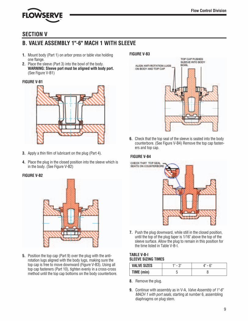
1. Mount body (Part 1) on arbor press or table vise holdingone flange.
2. Place the sleeve (Part 3) into the bowl of the body.WARNING: Sleeve port must be aligned with body port.(See Figure V-B1)
FIGURE V-B1
3. Apply a thin film of lubricant on the plug (Part 4).
4. Place the plug in the closed position into the sleeve which isin the body. (See Figure V-B2)
FIGURE V-B2
5. Position the top cap (Part 9) over the plug with the anti-rotation lugs aligned with the body lugs, making sure thetop cap is free to move downward (Figure V-B3). Using alltop cap fasteners (Part 10), tighten evenly in a cross-crossmethod until the top cap bottoms on the body counterbore.
9
Flow Control Division
Section 1.0
SECTION V
B. VALVE ASSEMBLY 1"-6" MACH 1 WITH SLEEVE
FIGURE V-B3
6. Check that the top seal of the sleeve is seated into the bodycounterbore. (See Figure V-B4) Remove the top cap fasten-ers and top cap.
FIGURE V-B4
7. Push the plug downward, while still in the closed position,until the top of the plug taper is 1/16" above the top of thesleeve surface. Allow the plug to remain in this position forthe time listed in Table V-B-I.
TABLE V-B-ISLEEVE SIZING TIMES
VALVE SIZES 1" - 3" 4" - 6"
TIME (min) 5 8
8. Remove the plug.
9. Continue with assembly as in V-A, Valve Assembly of 1"-6"MACH 1 with port seals, starting at number 6, assemblingdiaphragms on plug stem.
(V-300) Mach 1 IOM 12/5/02 11:23 AM Page 10 Dan K. Snelson Clients:019-FLOWSERVE Valves:019-Job Files:019-Closed Jobs:

NOTE: Part number reference is shown in Figure VI-1.
1. Normal procedures for field replacement of port seals orsleeves are to be followed. Refer to V-A, steps 1-5, andV-B, steps 1-8.
2. The fireseal top seal assembly differs from the standardMach 1 top seal and is completed per the followinginstructions.
FIGURE VI-1TYPICAL ASSEMBLY OF FIRESEAL MACH 1
3. The PFA diaphragm (Part 19) is to be flared on a taperedbar just enough to slip over the plug stem (Fig. VI-2)
FIGURE VI-2
4. The PFA diaphragm is placed over the plug stem with thelip down using the diaphragm guide (Figure VI-3). Theplug stem should be checked for nicks before installingthe PFA diaphragm. Nicks on this surface could result inscratches on the lip of the diaphragm.
FIGURE VI-3
5. The metal diaphragm (Part 20) is placed over the plugstem just far enough to enlarge the ID to conform to theplug stem and then removed (Figure VI-4).
FIGURE VI-4
10
Flow Control Division
Section 1.0
SECTION VI
ASSEMBLY SPECIFICATIONS - FIRESEAL VALVES 1"-6" MACH 1
16
14
12
10
9
8
7
20
19
43
2
1
11
13
15
18
17
(V-300) Mach 1 IOM 12/5/02 11:23 AM Page 11 Dan K. Snelson Clients:019-FLOWSERVE Valves:019-Job Files:019-Closed Jobs:
SECTION VI
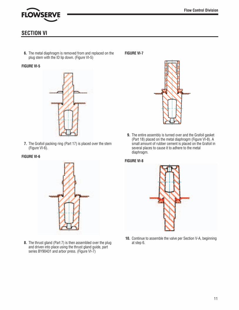
6. The metal diaphragm is removed from and replaced on theplug stem with the ID lip down. (Figure VI-5)
FIGURE VI-5
7. The Grafoil packing ring (Part 17) is placed over the stem(Figure VI-6).
FIGURE VI-6
8. The thrust gland (Part 7) is then assembled over the plugand driven into place using the thrust gland guide, partseries BY90431 and arbor press. (Figure VI-7)
FIGURE VI-7
9. The entire assembly is turned over and the Grafoil gasket(Part 18) placed on the metal diaphragm (Figure VI-8). Asmall amount of rubber cement is placed on the Grafoil inseveral places to cause it to adhere to the metaldiaphragm.
FIGURE VI-8
10. Continue to assemble the valve per Section V-A, beginningat step 6.
11
Flow Control Division
Section 1.0
(V-300) Mach 1 IOM 12/5/02 11:23 AM Page 12 Dan K. Snelson Clients:019-FLOWSERVE Valves:019-Job Files:019-Closed Jobs:
Or Consult Your Local Stocking Distributor
A T O M A C
Flowserve has the answer to your corrosion resistant, quarter-turn valving needs.
Printed in U.S.A.August 2002
© Flowserve Corporation
Clockwise from top right.
Durco® BTV-2000PTFE or UHMWPE lined chemical service valve
Atomac®
Lined ball valves• ANSI/ISO, standard and full port• Specialty valves• Valve products and accessories
Durco® Sleeveline®
Non-lubricated, PTFE-sleeved plug valves• G4 Isolation• G4E – DIN Mounting Pad• G4 Marathon™• TSG4 Severe Service
Durco® T-Line®
Non-lubricated, PTFE-lined plug valves
Big Max® ButterflyHigh performance valves
Durco® Microfinish™Alloy ball valves
Automax®
Valve automationsystems• Actuators• Controls with
smart technology• Accessories
For more information, contact:
Flowserve CorporationFlow Control Division1978 Foreman DriveCookeville, Tennessee 38501Phone: 931 432 4021Fax: 931 432 3105www.flowserve.com
Flowserve Pte. Ltd.12 Tuas Avenue 20Republic of Singapore 638824Phone: 65 862 3332Fax: 65 862 2800
Flowserve Ahaus GmbHVon Braun Straße 19aD-48683 AhausGermanyPhone: +49 2561 686-0Fax: +49 2561 686-39
(V-300) Mach 1 IOM 12/5/02 11:22 AM Page 1 Dan K. Snelson Clients:019-FLOWSERVE Valves:019-Job Files:019-Closed Jobs: