v. c. koo c. h. lim k. a. mahmood p. n. tan · · 2018-01-10abstract|a new unmanned aerial...
TRANSCRIPT
Progress In Electromagnetics Research, Vol. 122, 245–268, 2012
A NEW UNMANNED AERIAL VEHICLE SYNTHETICAPERTURE RADAR FOR ENVIRONMENTAL MONI-TORING
V. C. Koo1, Y. K. Chan1, *, V. Gobi1, M. Y. Chua1,C. H. Lim1, C. S. Lim1, C. C. Thum1, T. S. Lim1, Z. Ahmad2,K. A. Mahmood2, M. H. Shahid2, C. Y. Ang1, W. Q. Tan1,P. N. Tan1, K. S. Yee1, W. G. Cheaw1, H. S. Boey1,A. L. Choo1, and B. C. Sew1
1Faculty of Engineering & Technology, Multimedia University, JalanAyer Keroh Lama, Bukit Beruang, Melaka 75450, Malaysia2Malaysian Remote Sensing Agency, No. 13, Jalan Tun Ismail, 50480Kuala Lumpur, Malaysia
Abstract—A new Unmanned Aerial Vehicle (UAV) SyntheticAperture Radar (SAR) has been developed at Multimedia University,in collaboration with Agency of Remote Sensing Malaysia. The SARoperates at C-band, single V V -polarization, with 5m × 5m spatialresolution. Its unique features include compact in size, light weight,low power and capable of performing real-time imaging. A seriesof field measurements and flight tests has been conducted and goodquality SAR images have been obtained. The system will be used formonitoring and management of earth resources such as paddy fields, oilpalm plantation and soil surface. This paper reports the system designand development, as well as some preliminary results of the UAVSAR.
1. INTRODUCTION
Radar is the abbreviation for “Radio Detection and Ranging”. Itoperates by radiating electromagnetic energy through a transmittingantenna and detecting the reflected or scattered signal from thetarget [1]. SAR is an imaging radar which utilizes relative motionbetween an antenna and the target under observation to synthesizea very long antenna via signal processing [2]. As compared to
Received 26 September 2011, Accepted 2 November 2011, Scheduled 18 November 2011* Corresponding author: Yee Kit Chan ([email protected]).

246 Koo et al.
the conventional real aperture radar, SAR can obtain finer spatialresolution particularly in azimuth direction. The concept of SARcan be traced back to early 1950s when Carl Wiley proposed aDoppler beam sharpening system to improve the azimuth resolutionof radar [3, 4]. Today, SAR has become an important tool formicrowave remote sensing because of its capability to operate dayand night, and in nearly all weather conditions [5]. It has widerange of applications, including sea and ice monitoring [6], mining [7],oil pollution monitoring [8], oceanography [9], snow monitoring [10],terrain classification [11] and so on. The potential of SAR in a diverserange of applications has led to the development of a number ofairborne and spaceborne SAR systems.
An unmanned aerial vehicle (UAV) is an unpiloted aircrafttypically found in the area of surveillance, reconnaissance as well asmilitary missions. The earliest UAV was found in 1916 [12], followedby a number of remote-controlled airplanes developed during and afterWorld War I for military applications. UAV is currently one of themostrapid growth research areas due to its increased importance inmilitary operations [13]. The role of a UAV system falls mainly inreconnaissance and surveillance missions that utilize remote sensinginstruments such as electro-optical (EO) sensors, infrared (IR) sensorsand synthetic aperture radars (SAR). The increased popularity of aUAV system compared to a conventional aircraft is due to a few factors.There is no risk of losing human life especially for risky operations.The over loading of a manned aircraft has to be limited to 10 g dueto human physical limitations but it can be increased up to 20 g forUAV. There is also no concern on human fatigue and boredom in a longUAV mission. The weight of the human pilots is roughly equivalent to15% of the effective load of a military aircraft, while the pilot relatedsupporting and emergency systems cost as much as 50% of the totalcost of the aircraft [13]. Therefore the size of a UAV is only about 60%of the size of a manned aircraft with the same performance and theprice for a UAV system is expected to be 40% less than the cost of amanned solution [13, 14].
In terms of remote sensing applications, UAV-based imagingradar such as SAR has great potential due to its all-day, all-weathercapabilities. As compared to conventional airborne or space-borneSAR systems, UAV SARs have several advantages which include lowcost, low risk and timely operations.This has led to the developmentof a number of UAV SAR systems in recent years.
A low cost, compact and low power micro-SAR (µSAR) systemhas been developed by the Brigham Young University (BYU) [15].The µSAR is based on a linear frequency modulated continuous

Progress In Electromagnetics Research, Vol. 122, 2012 247
wave (LFM-CW) configuration, which has smaller size and powerrequirements as compared to a conventional pulsed SAR system. Thisenables the BYU µSAR to fly on a small UAV, further reducing the costof operation. The µSAR was designed to image Arctic sea ice. Thetarget UAV has a 6-foot wingspan, flies at low-altitudes (< 300m),with limited power to supply to the payload. European AeronauticDefence and Space Company (EADS) has developed a miniaturisedSAR (MISAR) sensor that was specially designed for UAVs withstringent payload size, weight and power (SWP) constraints. TheLUNA UAV of the German manufacturer EMT was chosen as thereference platform. LUNA has a take-off weight in the order of35 kg and its payload weight is restricted to 4 kg. The flyingaltitude of LUNA is between 300–2000 m with the velocity of 10–40m/s. This UAVSAR will be operated at stripmap mode with swathwidth of 500–1000 m. In order to achieve SWP requirement, theFMCW configuration is employed. The Jet Propulsion Laboratory(JPL) has designed and developed a L-band SAR for repeat passdeformation measurements on a UAV platform [16–18]. The SARsystem is operated at a wavelength of 0.2379 m (L-band, 1.26 GHz)and bandwidth of 80MHz. The pulse duration is designed at 40msecwith PRF of 350 Hz (interleaving H and V transmit polarizations). Itis a fully polarimetric and repeat pass interferometry SAR system. TheUAVSAR is able to obtain a range swath of 16 km with look agle of30 to 60 degree. The system will nominally operate at 45,000 ft. BothALTAIR and the Proteus can be used for this SAR system.
Research Establishment for Applied Science (FGAN) is inthe progress of developing ARTINO (Airborne Radar for Threedimensionally Imaging and Nadir Observation) [19–21]. It comprisesa low flying UAV, which will be able to map a directly overflownscene into a high resolution three-dimensional image by lookingperpendicularly downward. With a wingspan of only 4m and a modularstructure the UAV can be split up into small segments and easilytransported to the area of interest. Due to the light weight of only25 kg it is possible to fly at a slow speed of approximately 15 m/s. SinceARTINO is a low flying UAV, the 3D imaging radar can be designedfor short range. Hence, the average transmitting power is only a fewWatts.
A commercial available UAVSAR — Lynx SAR has developedby Sandia National Laboratories [22, 23]. Lynx is a state-of-the-art, ultra-fine-resolution, real-time SAR and ground moving targetindicator (GMTI) radar. Sandia National Laboratories collaboratedwith General Atomics (GA) to design and build the Lynx systemto incorporate General Atomics’ design requirements for operation
248 Koo et al.
on their Predator, IGNAT, or Prowler II unmanned aerial vehicles(UAVs). AN/APY-8 Lynx II is a lightweight version of Lynx operatingon the US Air Force Predator RQ-1 UAV. Lynx is a Ku-bandmultimode radar. Its SAR modes include real-time 0.1 m resolutionspotlight and 0.3 m resolution stripmap modes. The radar can also scana large or small area for moving objects, detecting targets at speedstypical of vehicular movements (10–70 kph). The Lynx SAR operatesin the Ku-Band anywhere within the range 15.2 GHz to 18.2 GHz, with320W of transmitter power.
Many other UAVSAR systems are designed for governmentagency, research institution and private industry. An experimentalmillimetre band (34 GHz frequency) Synthetic Aperture Radar (SAR)sensor has been developed by Polytechnic University of Madrid,Spain [24]. It is a short-range (2 Km) high-resolution (30×30 cm2) SARsystem with bandwidth of 675.8 MHz and PRF of 1300Hz. ResearchInstitute of China Electronics Technology Group Corporation is alsodesigned a 35 GHz, 8 mm wavelength UAV-borne SAR [25]. Theresolution achieved by this UAVSAR is proved by flight experimentsthat have reached 0.85m × 0.45m. A Ka band, fully-polarized SARradar is developed by the Lincoln Laboratory. This millimeter-waveSAR imaging system has the bandwidth of 600MHz in order to assure0.3m range resolution. The strip is 440 m wide, the spot imagingarea is 150 m × 150m, and the azimuth resolution is 0.3 m [25]. ItalySalenia Corporation has developed a UAV-borne MMW SAR whichcan perform ground mapping, detection, tracking and imaging of slow-speed objects. The operating frequency is 35 GHz. The SAR systemweight 60 kg and takes up 0.05 m3. The waveguide slotted antennais 1 m long, 0.24m wide and 2 kg weight. Pulse width 6µs andbandwidth is 40 MHz. The range resolution corresponding to the pulsecompression is 5m. Microwave Remote Sensing Laboratory, Centerfor Environmental Remote Sensing, Chiba University is currentlydeveloping its Circular Polarization SAR (CP-SAR) sensor which canbe used in UAV as well as satellite based platform [26]. This sensoris operated with center frequency on L band (1.27 GHz) and 10 MHzof chirp pulse bandwidth. The sensor is designed as a low cost,simple, light, strong, low power, low profile configuration to transmitand receive left-handed circular polarization (LHCP) and right-handedcircular polarization (RHCP), where the transmission and receptionare working in RHCP and RCHP + LCHP, respectively.
In late 2008, a new UAVSAR project was initiated at MultimediaUniversity (MMU), Malaysia, in collaboration with Agency RemoteSensing of Malaysia (ARSM). This project was started afterpreparatory studies in the previous year [27–31]. The proposed system
Progress In Electromagnetics Research, Vol. 122, 2012 249
is a C-band, V V -polarization, miniature SAR mounted on a smallUAV. The UAVSAR system is designed to operate at low altitudeswith low transmit power in order to optimize the operating cost. Theconstruction of the SAR sensor was completed in early 2010. A seriesof indoor and outdoor testing and measurements has been carriedout to verify the performance of the system. At the end of 2010,flight missions have been conducted at Mersing, Johor. High qualitySAR images were obtained which demonstrated the capabilities of theUAVSAR for remote sensing applications in Malaysia.
This paper presents the system design and development, as well assome preliminary results of the UAVSAR. Section 2 outlines the majordesign issues and considerations for UAVSAR. Section 3 describesthe development of various SAR subsystems including the microstrippatch antenna, the radar electronics, the embedded SAR controllerand processor, and the UAV platform. Section 4 presents some of thepreliminary results obtained by the UAVSAR, which include ground-based SAR experiments and fight tests. Finally, Section 5 concludesthe paper.
2. DESIGN CONSIDERATIONS
The primary goal of this research project is to develop an UAV basedSAR system which capable to illuminate terrain and construct theimage of the scanned area. High level design consideration have beencarefully considered and presented in this section.
2.1. Operating Frequency
C-band (4–8GHz) frequency is widely used for high-resolution landimaging, agricultural monitoring and ocean observations. In thisfrequency band, incident wave tends to be reflected more by vegetationcanopies rather than the surface layer. This penetration characteristicallows the canopy biomass and soil below the canopy to be analyzed.The center frequency of the UAVSAR is selected at 5.3 GHz,which is within the allowable spectrum (5250–5460 MHz) defined byInternational Telecommunication Union (ITU) for Earth ExplorationSatellite System (EESS) [32]. Beside the reason of having lowabsorption in the atmospheric-window region, the size of a C-bandantenna is considerably small and most of the RF components areeasily available.
250 Koo et al.
2.2. Mode of Operation
The two most common SAR imaging modes are stripmap and spotlight.The stripmap is a standard mode of SAR operation, widely used byairborne SAR sensors where a strip (swath) to the side of the aircraftis imaged. On the other hand, a spotlight SAR steers its antennabeam to continuously illuminate a specific terrain patch during datacollection. The spotlight mode is suitable to collect fine-resolution datafrom localized areas, while the stripmap mode is more efficient whenused for coarse-resolution mapping of large regions. In our design, thestripmap mode is the preferred choice.
2.3. Polarization
Single polarization mode is proposed for simple classification andmulti-temporal change detection. V V -polarization is the preferredconfiguration since it is sensitive to the vegetation’s vertical canopystructure, thus providing the opportunity for crop type and growthstage discrimination.
2.4. Dynamic Range
Based on the measurement results reported in numerous literatures,it is found that typical values of scattering coefficients for variouscategories of terrain fall in the range from 0 dB to −30 dB [33].Therefore, a wide dynamic range (> 30 dB) is needed to accommodatethe measurement of various types of terrain.
2.5. Resolution
Typical resolution of airborne SAR ranges from 1 m to 20 m. It dependsmostly on the application requirements. Since the main objective is tomonitor earth resources such as vegetation fields, resolution of 5m×5 mfor both range and azimuth direction will be adequate.
2.6. Antenna Requirements
A planar, lightweight, small size, linearly polarized microstrip patcharray panel is proposed. The center frequency for the array is set at5.3GHz, with more than 80 MHz bandwidth. The directive gain of thepanel should be more than 15 dBi for good detection in the presence ofnoise. Due to the limited space of the UAV platform, the antenna willbe mounted directly underneath the fuselage. The beamwidth will betilted 25◦ off nadir for side-looking operation.
Progress In Electromagnetics Research, Vol. 122, 2012 251
2.7. Signal Processor
The on-board facility consists of a high-speed analog-to-digitalconverter, a front-end processor, and a high-density digital datarecorder to store the raw data. The SAR images should be produced byboth ground processing facility and onboard processor. Real-time datacapturing, recording and processing are desired for timely monitoringduring flight mission.
2.8. Motion Sensing
The irregular motion of the aircraft due to atmospheric turbulence willseriously affect the image quality. In particular, the change of altitudecauses the image out of focus. In this system, an embedded inertialnavigation system (INS) and global positioning system (GPS) are usedto provide integrated flight information.
2.9. UAV Platform
A small UAV will be used to install the radar system. The platformshould support true ground speed of approximately 30–40 m/s withoperating altitude at about 1000 m. The desired payload is at least20 kg.
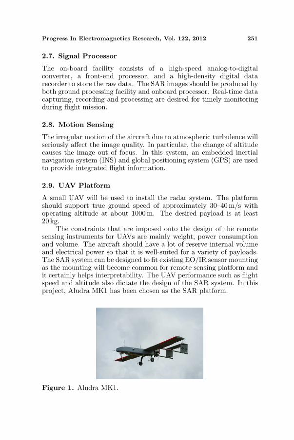
The constraints that are imposed onto the design of the remotesensing instruments for UAVs are mainly weight, power consumptionand volume. The aircraft should have a lot of reserve internal volumeand electrical power so that it is well-suited for a variety of payloads.The SAR system can be designed to fit existing EO/IR sensor mountingas the mounting will become common for remote sensing platform andit certainly helps interpretability. The UAV performance such as flightspeed and altitude also dictate the design of the SAR system. In thisproject, Aludra MK1 has been chosen as the SAR platform.
Figure 1. Aludra MK1.
252 Koo et al.
Aludra MK1 is developed by UST (Unmanned SystemsTechnology), Malaysia with the dimension of 4.27m and wingspanof 4.88 m. The image of Aludra MK1 is shown in Figure 1. Thetypical speed of MK1 is 35m/s and up to maximum speed of 61 m/s.Endurance of this UAV is about 3 hrs. However limited payload weightis a challenge. The working space is about 27 cm (W ) × 35 cm (L) ×25 cm (H) and maximum payload of 20 kg. Thus extra attentions needto be taken for the dimension and weight of the SAR sensor andantenna size. Therefore a new chassis of the SAR sensor need to bedesign and constructed for installing all SAR subsystem.
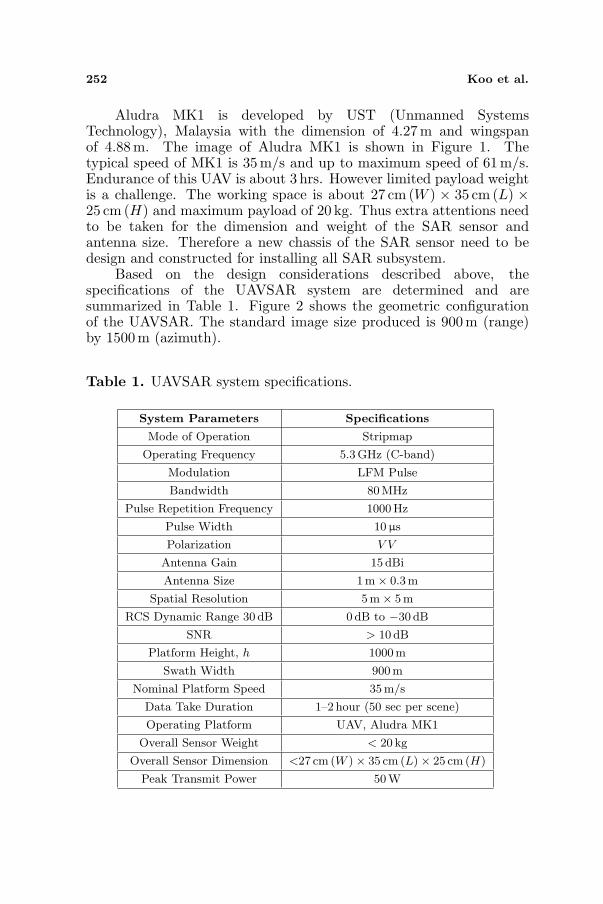
Based on the design considerations described above, thespecifications of the UAVSAR system are determined and aresummarized in Table 1. Figure 2 shows the geometric configurationof the UAVSAR. The standard image size produced is 900 m (range)by 1500m (azimuth).
Table 1. UAVSAR system specifications.
System Parameters Specifications
Mode of Operation Stripmap
Operating Frequency 5.3GHz (C-band)
Modulation LFM Pulse
Bandwidth 80MHz
Pulse Repetition Frequency 1000Hz
Pulse Width 10 µs
Polarization V V
Antenna Gain 15 dBi
Antenna Size 1m× 0.3m
Spatial Resolution 5m× 5m
RCS Dynamic Range 30 dB 0dB to −30 dB
SNR > 10 dB
Platform Height, h 1000m
Swath Width 900m
Nominal Platform Speed 35m/s
Data Take Duration 1–2 hour (50 sec per scene)
Operating Platform UAV, Aludra MK1
Overall Sensor Weight < 20 kg
Overall Sensor Dimension <27 cm (W )× 35 cm (L)× 25 cm (H)
Peak Transmit Power 50W
Progress In Electromagnetics Research, Vol. 122, 2012 253
40o
25o
1000 m
912 m
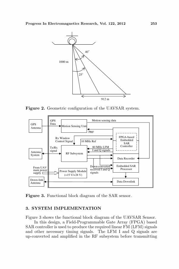
Figure 2. Geometric configuration of the UAVSAR system.
RF Subsystem
Motion Sensing Unit
Power Supply Module
(+15 V/+28 V)
Data Downlink
Data Recorder
Antenna
GPS
Antenna
Data
Tx/Rx signal
80 MHz LFM
I and Q signals
10 MHz Ref
Down-converted received I and Q signals
Rx Window
Control Signal
Motion sensing data
SARController
Antenna
System
Down-link
From UAVmain powersupply
GPS
PRF
EmbeddedFPGA-based
Embedded SARProcessor
Figure 3. Functional block diagram of the SAR sensor.
3. SYSTEM IMPLEMENTATION
Figure 3 shows the functional block diagram of the UAVSAR Sensor.In this design, a Field-Programmable Gate Array (FPGA) based
SAR controller is used to produce the required linear FM (LFM) signalsand other necessary timing signals. The LFM I and Q signals areup-converted and amplified in the RF subsystem before transmitting

254 Koo et al.
out via an antenna system. The antenna system is implemented byusing microstrip patch arrays. The returned echoes are amplified anddown-converted into an intermediate frequency (IF), at which theyare further digitized and stored in the data recorder. A replica ofthe IF signal is fed into an embedded SAR processor for real-timeimage formation. The resultant image will be transmitted to theground station via a 2.4GHz data downlink unit. An integratedInertial Measurement Unit (IMU) with Global Positioning System(GPS) receiver is also developed to provide the necessary platformmotion information.
3.1. RF Subsystem
The block diagram of the RF subsystem is shown in Figure 4. Basicallyit can be divided into two sub-sections: the transmitter and thereceiver. At the transmitter front-end, the I (In-phase) and the Q(quadrature-phase) chirp signals are mixed with the carrier frequency(5.3GHz) via an up-convert mixer. The output of the mixer isamplified by a power amplifier (PA). A RF switch is used to turnon the transmitting window, where its on-time duration is selectablebased on mission requirements. The signal is then fed to a bandpassfilter to reject unwanted signal outside the desired frequency band,and further amplified by a high power amplifier (HPA) to boost up thepower for long range transmission. The average output power is about160mW for nominal operating range of 1 km.
Figure 4. Functional block diagram of the SAR RF subsystem.
Progress In Electromagnetics Research, Vol. 122, 2012 255
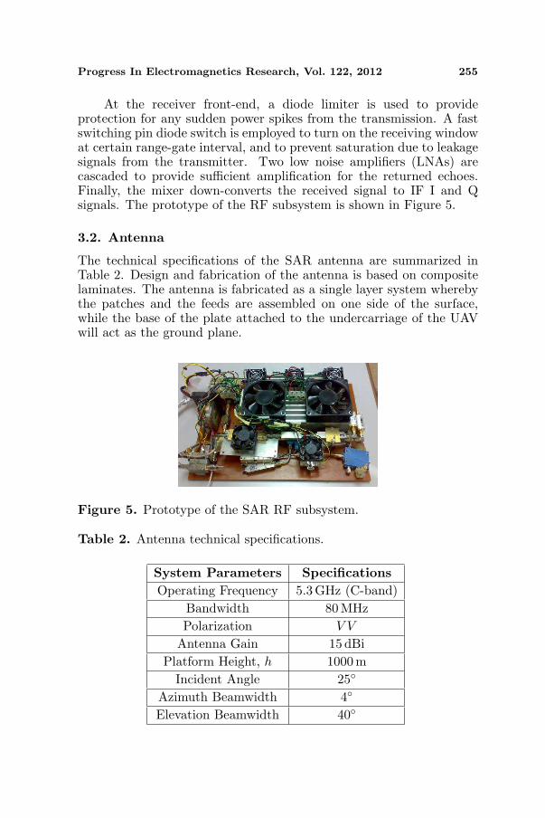
At the receiver front-end, a diode limiter is used to provideprotection for any sudden power spikes from the transmission. A fastswitching pin diode switch is employed to turn on the receiving windowat certain range-gate interval, and to prevent saturation due to leakagesignals from the transmitter. Two low noise amplifiers (LNAs) arecascaded to provide sufficient amplification for the returned echoes.Finally, the mixer down-converts the received signal to IF I and Qsignals. The prototype of the RF subsystem is shown in Figure 5.
3.2. Antenna
The technical specifications of the SAR antenna are summarized inTable 2. Design and fabrication of the antenna is based on compositelaminates. The antenna is fabricated as a single layer system wherebythe patches and the feeds are assembled on one side of the surface,while the base of the plate attached to the undercarriage of the UAVwill act as the ground plane.
Figure 5. Prototype of the SAR RF subsystem.
Table 2. Antenna technical specifications.
System Parameters SpecificationsOperating Frequency 5.3 GHz (C-band)
Bandwidth 80MHzPolarization V V
Antenna Gain 15 dBiPlatform Height, h 1000 m
Incident Angle 25◦
Azimuth Beamwidth 4◦
Elevation Beamwidth 40◦
256 Koo et al.
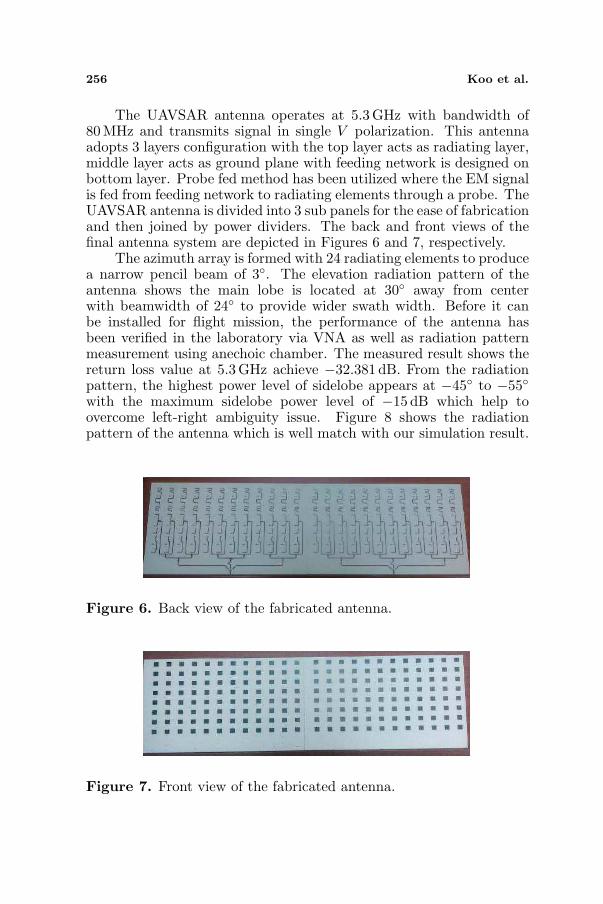
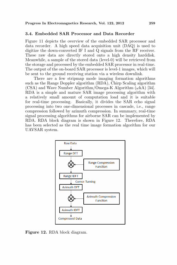
The UAVSAR antenna operates at 5.3GHz with bandwidth of80MHz and transmits signal in single V polarization. This antennaadopts 3 layers configuration with the top layer acts as radiating layer,middle layer acts as ground plane with feeding network is designed onbottom layer. Probe fed method has been utilized where the EM signalis fed from feeding network to radiating elements through a probe. TheUAVSAR antenna is divided into 3 sub panels for the ease of fabricationand then joined by power dividers. The back and front views of thefinal antenna system are depicted in Figures 6 and 7, respectively.
The azimuth array is formed with 24 radiating elements to producea narrow pencil beam of 3◦. The elevation radiation pattern of theantenna shows the main lobe is located at 30◦ away from centerwith beamwidth of 24◦ to provide wider swath width. Before it canbe installed for flight mission, the performance of the antenna hasbeen verified in the laboratory via VNA as well as radiation patternmeasurement using anechoic chamber. The measured result shows thereturn loss value at 5.3 GHz achieve −32.381 dB. From the radiationpattern, the highest power level of sidelobe appears at −45◦ to −55◦with the maximum sidelobe power level of −15 dB which help toovercome left-right ambiguity issue. Figure 8 shows the radiationpattern of the antenna which is well match with our simulation result.
Figure 6. Back view of the fabricated antenna.
Figure 7. Front view of the fabricated antenna.

Progress In Electromagnetics Research, Vol. 122, 2012 257
Figure 8. Measured radiation pattern of SAR antenna.
Figure 9. Block diagram of SAR motion sensing unit.
3.3. Motion Sensing Unit
An embedded motion sensing unit has been developed to collect therequired information for motion compensation. These include datasuch as time, longitude, latitude, altitude, 3-axis accelerations and3-axis angular velocity (raw, pitch and yaw). The block diagram ofthe SAR motion sensing unit is illustrated in Figure 9. The motionsensing of SAR sensor is achieved by integrating both global positioning

258 Koo et al.
system (GPS) and strapdown inertial moment unit (IMU). The GPSis able to provide instantaneous position data on the SAR sensorwith no accumulation errors, but suffers a relatively low data rate(5Hz). On the other hand, the strapdown IMU provides higher datarate (167 Hz) for position, velocity and orientation estimations, butare subject to sensor’s accumulation errors. Thus, the integration ofGPS and IMU suppresses the shortcomings of each individual system,namely, the GPS’s low data rate and IMU’s accumulation errors. Also,the integration combines the advantages of both systems, such as thehigh accuracy positioning data in GPS and the short term stability ofIMU.
As shown in the block diagram of Figure 9, the data from GPS andIMU were compared and feed into an extended Kalman filter (EKF)for optimal errors prediction and estimation. The estimated errorswill be used to correct the original measurements. Due to data rateinconsistency between IMU and GPS, the data fusion event will onlytake place when GPS data was available. In the event of no GPSdata the IMU will correct itself using the last predicted errors. Theconstructed motion sensing unit is shown in Figure 10.
11 cm15 cm
4 cm
Figure 10. The integrated IMU-GPS motion sensing unit.
DAQ
UnitRaw Data in
High Density
Harddisk
High Speed SAR
ProcessorWireless
Downlink
Figure 11. Overview of the embedded SAR processor and datarecorder.
Progress In Electromagnetics Research, Vol. 122, 2012 259
3.4. Embedded SAR Processor and Data Recorder
Figure 11 depicts the overview of the embedded SAR processor anddata recorder. A high speed data acquisition unit (DAQ) is used todigitize the down-converted IF I and Q signals from the RF receiver.These raw data are directly stored onto a high density harddisk.Meanwhile, a sample of the stored data (level-0) will be retrieved fromthe storage and processed by the embedded SAR processor in real-time.The output of the on-board SAR processor is level-1 images, which willbe sent to the ground receiving station via a wireless downlink.
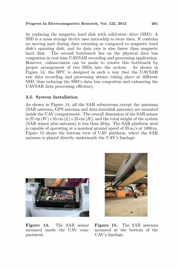
There are a few stripmap mode imaging formation algorithmssuch as the Range Doppler algorithm (RDA), Chirp Scaling algorithm(CSA) and Wave Number Algorithm/Omega-K Algorithm (ωkA) [34].RDA is a simple and mature SAR image processing algorithm witha relatively small amount of computation load and it is suitablefor real-time processing. Basically, it divides the SAR echo signalprocessing into two one-dimensional processes in cascade, i.e., rangecompression followed by azimuth compression. In summary, real-timesignal processing algorithms for airborne SAR can be implemented byRDA. RDA block diagram is shown in Figure 12. Therefore, RDAhas been selected as the real time image formation algorithm for ourUAVSAR system.
Figure 12. RDA block diagram.

260 Koo et al.
Figure 13. Block diagram of enhanced UAVSAR data recording andprocessing system.
The embedded SAR processor is implemented using a HighPerformance Computer (HPC). The selected motherboard has a Core2-based CPU and it is capable of supporting up to 4 GB of RAM.It also has a built-in CUDA (Compute Unified Device Architecture)compatible graphic processing unit. A 12-bit high-speed ADC card isemployed for the implementation of the DAQ unit. This ADC cardhas two-channel inputs and it is capable of simultaneous samplingup to 250 MHz. The digitized data are transferred to the HPC viaPCI express interface at 1.25 GBytes/s data rate. Figure 13 showsthe block diagram of the enhanced UAVSAR data acquisition andprocessing system. It is worth mentioning that UAVSAR raw data isacquired using the ADC with a designed data rate of 7.5Mbytes/s.After the conversion, the ADC stored the data in HPC’s RandomAccess Memory (RAM) temporarily, where the HPC will excerpt theinformation out of the RAM and saved it into local mass storagedevice. Here lies the first bottleneck of the designed system, wherea typical magnetic hard disk should not be used in UAV flight test dueto the vibration of the flight might potentially damaged the hard disk’sspinning disk with its read/write heads. This bottleneck can be resolve
Progress In Electromagnetics Research, Vol. 122, 2012 261
by replacing the magnetic hard disk with solid-state drive (SSD). ASSD is a mass storage device uses microchip to store data. It containsno moving part during data retaining as compared to magnetic harddisk’s spinning disk, and its data rate is also faster than magnetichard disk. The second bottleneck lies on the physical data buscongestion in real time UAVSAR recording and processing application.However, enhancement can be made to resolve this bottleneck byproper arrangement of two SSDs into the system. As shown inFigure 13, the HPC is designed in such a way that the UAVSARraw data recording and processing always taking place at differentSSD, thus reducing the SSD’s data bus congestion and enhancing theUAVSAR data processing efficiency.
3.5. System Installation
As shown in Figure 14, all the SAR subsystems except the antennas(SAR antenna, GPS antenna and data downlink antenna) are mountedinside the UAV compartment. The overall dimension of the SAR sensoris 27 cm (W )×35 cm (L)×25 cm (H), and the total weight of the system(SAR sensor plus antenna) is less than 20 kg. The SAR platform usedis capable of operating at a nominal ground speed of 35 m/s at 1000 m.Figure 15 shows the bottom view of UAV platform, where the SARantenna is placed directly underneath the UAV’s fuselage.
Figure 14. The SAR sensormounted inside the UAV com-partment.
Figure 15. The SAR antennamounted at the bottom of theUAV’s fuselage.

262 Koo et al.
4. PRELIMINARY RESULTS
A series of field experiment has been conducted in year 2010 to verifythe performance of the UAVSAR system. These include point targetmeasurement, and ground-based SAR experiments using a movingplatform. Flight tests were finally conducted at the end of 2010 toevaluate the overall performance of the SAR sensor.
82.5 m
20 m 20 m
starting point
SARSensorSensor Moving Direction
Figure 16. Experimental setup for point target measurement.
Figure 17. The SAR image of a trihedral placed at 82.5 m.
Progress In Electromagnetics Research, Vol. 122, 2012 263
4.1. Point Target Measurement
Figure 16 shows the experimental setup for point target measurement.The test site was a public field with low background clutter. A trihedralcorner reflector was placed on a polystyrene structure of about 1.5 min height, located 82.5 m from the SAR transmitting antenna. Themeasurement was conducted by employing the stop-and-go approach,where the SAR sensor was manually moved to a pre-defined cross range(azimuth) position for every single range bin data capturing. The totalcross range travelled was 40 m, which yields 400 points of azimuth datawith 0.10 m spacing. Figure 17 shows a SAR image generated from thisexperiment. A strong target is clearly shown at location 82.5m. Themeasured 3 dB azimuth resolution is 0.78m, and the peak sidelobe levelis −12.23 dB.
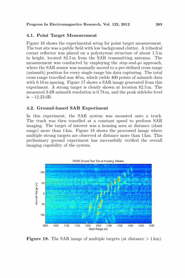
4.2. Ground-based SAR Experiment
In this experiment, the SAR system was mounted onto a truck.The truck was then travelled at a constant speed to perform SARimaging. The target of interest was a housing area at distance (slantrange) more than 1 km. Figure 18 shows the processed image wheremultiple strong targets are observed at distance more than 1 km. Thispreliminary ground experiment has successfully verified the overallimaging capability of the system.
Figure 18. The SAR image of multiple targets (at distance > 1 km).

264 Koo et al.
Figure 19. The SAR image of the calibration site at Mersing.
4.3. Fight Tests
Preliminary flight tests have been conducted in December 2010 atMersing, Malaysia. During the 6-day flight mission, more than 200sets of SAR raw data were collected. Eleven trihedral corner reflectors,arranged in three groups, were used as the point targets for externalcalibration. All the trihedral corner reflectors were placed in a straightline and perpendicular to the flight path of the UAV. Figure 19 showsthe SAR image of the calibration site. Signatures such as the pointtargets, UAV runway, pit crew tent and ground control system areclearly observed.
Figures 20 and 21 show two samples of SAR images capturedon Dec. 5th and Dec. 8th, 2010, respectively, with comparison to theGoogle Earth map of the same site. Clear signatures of river, roads,urban and forested areas are observed.

Progress In Electromagnetics Research, Vol. 122, 2012 265
Range
Azimuth
(a) (b)
Figure 20. (a) Google earthmap. (b) SAR image-1 at Mersingsite.
Range
Azimuth
(a) (b)
Figure 21. (a) Google earthmap. (b) SAR image-2 at Mersingsite.
5. CONCLUSIONS
A miniature SAR system operated on a small UAV platform hasbeen successfully designed and developed. Various design parametershave been carefully studied and determined in the system leveldesign. Implementation of SAR system with especial attention to thedimension and size of the sensor chassis and antenna due to constrainsof the UAV in particularly the limitation in weight and volume. Aseries of filed measurement and flight test has been conducted to verifythe performance of the UAVSAR sensor. This new system will serveas a test-bed for demonstrating SAR technology and acquiring datafor environmental monitoring in Malaysia.
ACKNOWLEDGMENT
This project is funded by Agency of Remote Sensing Malaysia underMinistry of Science, Technology and Innovation, Malaysia.

266 Koo et al.
REFERENCES
1. Skolnik, M. I., Radar Handbook, McGraw-Hill, New York, 1970.2. Curlander, J. C. and R. N. McDonough, Synthetic Aperture
Radar: System and Signal Processing, A Wiley IntersciencePublication, 1991.
3. Wiley, C. A., “Synthetic aperture radar — A paradigm fortechnology evolution,” IEEE Trans. on Aerospace and ElectronicSystems, Vol. 21, 440–443, 1985.
4. Ausherman, D. A., A. Kozma, J. L. Walkeretal, H. M. Jones, andE. C. Poggio, “Developments in radar imaging,” IEEE Trans. onAerospace and Electronic Systems, Vol. 20, No. 4, 363–440, 1984.
5. Ulaby, F. T., R. K. Moore, and A. K. Fung, Microwave RemoteSensing-active and Passive, Vol. 2, Addison Wesley, 1981.
6. Drinkwater, M. K., R. Kwok, and E. Rignot, “Synthetic apertureradar polarimetry of sea ice,” Proceeding of the 1990 InternationalGeoscience and Remmote Sensing Symposium, Vol. 2, 1525–1528,1990.
7. Lynne, G. L. and G. R. Taylor, “Geological assessment of SIR-B imagery of the amadeus basin,” IEEE Trans. on Geosc. andRemote Sensing, Vol. 24, No. 4, 575–581, 1986.
8. Hovland, H. A., J. A. Johannessen, and G. Digranes, “Slickdetection in SAR images,” Proceeding of the 1994 InternationalGeoscience and Remmote Sensing Symposium, 2038–2040, 1994.
9. Walker, B., G. Sander, M. Thompson, B. Burns, R. Fellerhoff,and D. Dubbert, “A high-resolution, four-band SAR testbed withreal-time image formation,” Proceeding of the 1986 InternationalGeoscience and Remmote Sensing Symposium, 1881–1885, 1996.
10. Storvold, R., E. Malnes, Y. Larsen, K. A. Høgda, S. E. Hamran,K. Muller, and K. A. Langley, “SAR remote sensing of snowparameters in Norwegian areas — Current status and futureperspective,” Journal of Electromagnetic Waves and Applications,Vol. 20, No. 13, 1751–1759, 2006.
11. Kong, J. A., S. H. Yueh, H. H. Lim, R. T. Shin, and J. J. vanZyl, “Classification of earth terrain using polarimetric syntheticaperture radar images,” Progress In Electromagnetics Research,Vol. 3, 327–370, 1990.
12. Taylor, J. W. R., Jane’s Pocket Book of Remotely Piloted Vehicles,Collier Books, New York, 1977.
13. Yong, J. M., Secrets of Military Unmanned Aerial Vehicle, DefenseUniversity Publisher, China, 2004.

Progress In Electromagnetics Research, Vol. 122, 2012 267
14. Wall, R., Trial Run: Sigint Version, Not Maritime Patrol,Attracts Initial German Interest in Global Hawk, 42–43, McGraw-Hill, USA, 2003.
15. Zaugg, E. C., D. L. Hudson, and D. G. Long, “The BYUSAR: A small, student-built SAR for UAV operation,” The 2006International Geoscience and Remote Sensing Symposium, 411–414, 2006.
16. Hensley, S., K. Wheeler, G. Sadowy, et al., “Status of a UAVSARdesigned for repeat pass interferometry for deformation measure-ments,” IEEE MTT-S International Microwave Symposium Di-gest, 1453–1456, 2005.
17. Wheeler, K., S. Hensley, Y. Lou, T. Miller, and J. Hoffman, “AnL band SAR for repeat pass deformation measurements on a UAVplatform,” Proceedings of the IEEE Radar Conference, 317–322,2004.
18. Rosen, P. A., S. Hensley, K. Wheeler, G. Sadowy, T. Miller,S. Shaffer, R. Muellerschoen, C. Jones, H. Zebker, and S. Madsen,“UAVSAR: A new NASA airborne SAR system for science andtechnology research,” IEEE Conference on Radar, 22–29, 2006.
19. Rosen, P. A., S. Hensley, K. Wheeler, G. Sadowy, T. Miller,S. Shaffer, R. Muellerschoen, C. Jones, and S. Madsen, andH. Zebker, “UAVSAR: Airborne SAR system for research,” IEEEA&E Systems Magazine, 21–28, 2007.
20. Weib, M. and J. H. G. Ender, “A 3D imaging radar for smallunmanned airplanes — ARTINO,” Radar Conference, 209–212,2005.
21. Weiss, M., O. Peters, and J. Ender, “A three dimensional SARsystem on an UAV,” IEEE International Geoscience and RemoteSensing Symposium, 5315–5318, 2007.
22. Wells, L., K. Sorensen, A. Doerry, and B. Remund, “Developmentsin SAR and IFSAR systems and technologies at sandia nationallaboratories,” IEEE Aerospace Conference Proceedings, Vol. 2,1085–1095, 2005.
23. Tsunoda, S. I., F. Pace, J. Stence, M. Woodring, W. H. Hensley,A. W. Doerry, and B. C. Walker, “Lynx: A high-resolution syn-thetic aperture radar,” IEEE Aerospace Conference Proceedings,Vol. 5, 51–58, 2000.
24. Saldana, R. R. and F. P. Martinez, “Design of a millimetre syn-thetic aperture radar (SAR) onboard UAV’s,” IEEE InternationalConference on Electronics, Circuits and Systems, 1–5, 2007.
25. Peihong, R., “High-resolution 8 mm radar imaging technique,”

268 Koo et al.
International Conference on Radar, 1–3, 2006.26. Wissan, Y. V., I. Firmansyah, P. Rizki Akbar, J. T. Sri Sumantyo,
and H. Kuze, “Development of circularly polarized array antennafor synthetic aperture radar sensor installed on UAV,” ProgressIn Electromagnetics Research C, Vol. 19, 119–133, 2011.
27. Chan, Y. K., M. K. Azlindawaty, V. Gobi, B. K. Chung, andH. T. Chuah, “The design and development of airborne syntheticaperture radar,” IEEE International Geoscience and RemoteSensing Symposium, Vol. 2, 518–520, Jul. 2000.
28. Koo, V. C., Y. K. Chan, V. Gobi, T. S. Lim, B.-K. Chung, andH.-T. Chuah, “The MASAR project: Design and development,”Progress In Electromagnetics Research, Vol. 50, 279–298, 2005.
29. Chan, Y. K., B.-K. Chung, and H.-T. Chuah, “Transmitter andreceiver design of an experimental airborne synthetic apertureradar sensor,” Progress In Electromagnetics Research, Vol. 49,203–218, 2004.
30. Gobi, V., B. K. Chung, and H. T. Chuah, “Design of amicrostrip patch antenna for airborne SAR applications,” Journalof Electromagnetic Waves and Applications, Vol. 19, No. 12, 1687–1701, 2005.
31. Chua, M. Y. and V. C. Koo, “FPGA-based chirp generatorfor high resolution UAV SAR,” Progress In ElectromagneticsResearch, Vol. 99, 71–88, 2009.
32. International Telecommunication Union’s (ITU) World Radio-communication Conference 1997 (WRC-97).
33. Ulaby, F. T. and M. C. Dobson, Handbook of Radar ScatteringStatistics for Terrain, Artech House, Norwood, 1989.
34. Cumming, I. G. and F. H. Wong, Digital Processing of SyntheticAperture Radar Data, Artech House, Norwood, 2005.