v6n2 - lockheedmartin.com · 21 el caballito de los andes 22 emergency services full service...
TRANSCRIPT

... ," ' -..::: .. -. --
VOL. 6, NO. 2, APRIL · JUNE 1979
\
\.

2 Focal PointMatt Hodnett, Manager CustomerSupply Division
3 Keep a Tight Shipservice life, cleaning, care and hand-ling of door seals, adhesives, sealidentification, seal repair, clear visionwindshield panels, and door rigging
1 4 A R R Semergency rescues, space programsupport, weather reconnaissance,and atmospheric sampling
18 Cargo Floor Shoring
21 El Caballito de los Andes
22 Emergency Servicesfull service product support
24 T a t t o o
Cover. This month’s cover is a montage of twophotographs one showing a Hercules HC-130Hmaking a pick-up via the Fulton R e c o v e r ySystem and the other of a subject awaitingpickup. Photos courtesy of the USAF.
Published by Lockheed-Georgia Company, a Division ofLockheed Corporation. Information contained in thisissue i s considered by Lockheed-Georgia Company to beaccurate and authoritative: it should not be assumed, how-ever, that this material has received approval from anygovernmental agency or military service unless it isspecifically noted. This publication is for planning andinformation purposes only, and it is not to be construedas authority for making changes on aircraft or equipment,or as superseding any established operational or main-tenance procedures or policies. The following marks areregistered and owned by Lockheed Corporation:
“, “Lockheed”, “Hercules”, and “JetStar”.Written permission must be obtained from Lockheed-Georgia Company before republishing any material in thisperiodical. Address all communications to Editor, ServiceNews, Department 64-22, Zone 278, Lockheed-GeorgiaCompany, Marietta, Georgia. 30063. Copyright 1979Lockheed Corporation.
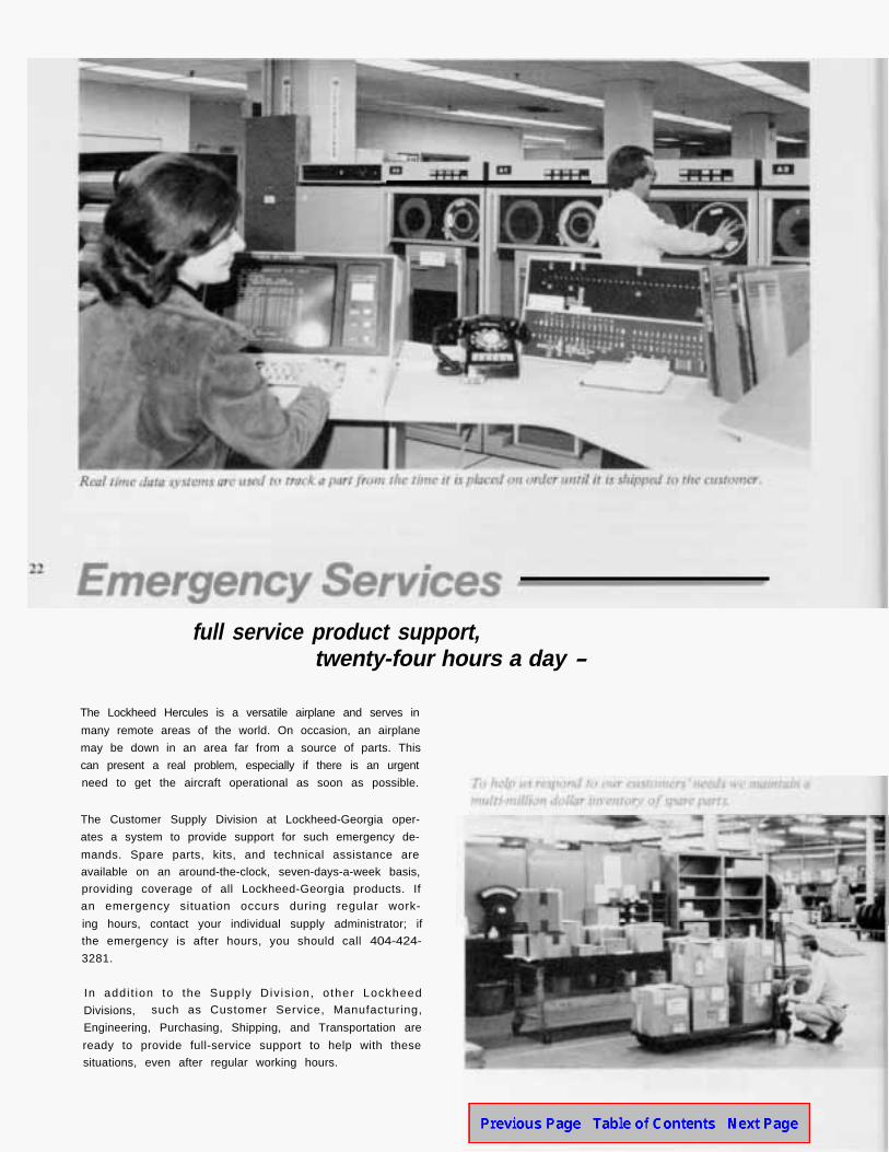
Another service of Lockheed is a computer system which can determine the status of acustomer’s part on a particular order. Real-time data systems are used to track a part fromthe time it is placed on order until it is shipped to the customer.
In addition to the use of this sophisticated equipment, we provide each customer with his ownsupply administrator (a one-to-one relationship) to provide personal service and quick responses.
Another important phase of Customer Supply is our component repair capability. The overhaul,repair and calibration of aircraft components is an exacting business requiring highly trained andexperienced personnel, specialized test equipment, and rigorous control procedures. We provideHercules operators with repair service for a variety of avionic, hydraulic and mechanical items.The level of repair service ranges from minor component replacement to major overhaul. Formore information on our component repair service, contact your individual supply administrator.
The inside back cover of this issue of Service News provides information on our emergency and“drop-in” repair services. If I or anyone in this division can help you with a supply problem,please do not hesitate to ask.
Support of our products is of tremendous importance to us at Lockheed. Even though CustomerSupply is only one area of support given the customer, the same dedication applies throughoutthe Lockheed organization.
Sincerelv.
PRODUCTDIRECTOR
M. M. Hodnett, ManagerCustomer Supply Division
SUPPORT LOCKHEED GEORGIA COMPANY,
MARIETTA. GEORGIA 30063
T.J. CLELAND
CUSTOMER SERVICE CUSTOMER SUPPLY
DIVISION DIVISION

/
•
I ! '
\
, ...
,,
' '. \
KEEP A TIGHT SHIP!
by: D. J . Lipscomb. Senior Material & Processes Engineer
R. W. Nazarowski, Senior Structures Design Engineer
/ '

Figure 1 Estimated annual fuel savings resulting from a 1%
reduction in drag.
The cumulative effect of such seal inefficiency and re-sulting drag can be surprising when viewed in terms ofannual fuel usage (Figure 1). The savings reflected byFigure 1 are really quite conservative. Commercial cargocarriers report that extremely “dirty” airplanes, such asthose with gross air leaks or misfaired structure, can sufferdrag increases of up to six percent over baseline config-urations.
The first rule to remember in repairing seals and seal-ants is cleanliness. Sealants and adhesives will not ad-here to a dirty surface. Also, if door seals are allowedto remain in prolonged contact with a contaminantsuch as hydraulic fluid, the seal will become soft andswollen. In this condition, seals are most easily dam-aged and can blow out under pressure. Fortunately,most C-130 seals are not permanently degraded by briefcontact with hydraulic oil. They can be restored to theiroriginal condition if fluid spills are properly cleaned fromthe surface and dirt and foreign matter are removed.
The areas of an aircraft most sensitive to drag are thenacelles, the forward fuselage, and the leading edge sec-tions of wings and tail. While the causes of drag are nu-
4 merous and elusive, one of the most common is air leak-age, and this can be corrected by proper sealing.
SERVICE LIFE
In order to maintain rubber seals in their best condition,the “two rag” system of cleaning is recommended. Useclean, dry, cotton wiping rags (Figure 2, Item 1) andeither aliphatic naptha solvent (Item 2) or trichloroethane(Item 3) as the cleaning fluid. Moisten one rag with thesolvent and wipe the seal clean, then wipe the seal dryimmediately with a second rag. Repeat the operation asmany times as necessary. Do not allow the solvent toevaporate on the seal. The structural surfaces which matewith the seals (seal strikers) must also be cleaned at thesame time as the seals, using the same technique.
Hercules seals have proven to be very rugged and re- Apply talc, soapstone or fluorocarbon powder (Item 12)liable in service under world-wide climatic conditions. to the seal in the areas that have been cleaned.
They must of course be maintained with periodic clean-ings, and removal of debris that could cause FOD (ForeignObject Damage). Routine checks of door rigging are alsorequired to assure proper operation and long life. Toolittle compression of the rubber seal will usually result inexcessive air leakage around the opening, while too muchcompression of the seal significantly reduces seal life.
CLEANING
whenever the floor panel is removed.

ITEMNO.
1
2
3
4
5
DESCRIPTION
Maternal CommercialVENDOR
Cotton Rags
Solvent
Solvent
Solvent
Dacron Fabr ic
Dacron Fabric
Rubber CoatedNylon Cloth
Silicone Adheswe1 Part RTV
Silicone Adheswe2 Part RTV
ChloropreneAdhesive
Silicone spongeCore
_
Naptha
Trichloroethane
Dry Cleaning
D-2000
D 117
No. RTV 157Alternate No.RTV 154
No. 93 076 1/2
No A-68-6
LS33763-1
Various Vendors
Various Vendors
Various Vendors
Various Vendors
Mohawk MillsAmsterdam, NY
Mohawk MillsAmsterdam, NY
Reeves. VulcanNew York, NY
General ElectricWaterford, MA
SPECIFICATIONS ANDNATIONAL STOCK NUMBER
DDD-R-30. Grade A
TT-N-95, Type II
0 T-620. Type I
P-D 680, Type I
Commerc ia l
6 Commercial Reinforcement
7 MIL-C-20696, Type I, Class 3 Reinforcement
8
9
10
11
Dow CorningMidland, Ml
B. F. GoodrichAkron, OH
Purosil CorporationHadbar DivisionAlhambra, CA
Various Vendors
CommercialAlternate Commercial orNSN 8040-00-181-8380
CommercialNSN 8030-00-043-1726
CommercialNSN 8040-01-016-5354
Commercial
FluorocarbonPowder
Polysulflde Sealant
Petrolatum
Silicone Compound
_
_
Vasel ine
DC 4
Ml L L 60326 Anti-Stick Coating
Various Vendors
Various Vendors
MIL S 8802. Class B-1/2NSN 8030-753 5004
VV-P-236
NSN 9150-00-250-0926
Dow Corning MIL-S 8660Midland, Ml NSN 6850-00-880 7616
Figure 2 CLEANING AND REPAIR MATERIALS FOR SEALS
Cleaning the rubber flapper seals over the drain open-ings in the lower pressure skin at or near butt line (BL)0.0 should be accomplished any time the center cargofloor panels are removed for access. Damaged or de-teriorated flappers should be replaced in accordancewith the procedures described in the applicable man-uals.
CARE AND HANDLING OF DOOR SEALS
Despite their rugged appearance, uninstalled door sealsare easily damaged. They must be given proper careand handling during storage, removal, and installationif they are to perform satisfactorily. The following are afew helpful hints for proper storage and handling of seals:
. Seals can become deformed as a result of poor storage.Be sure to provide proper support for those assemblieson the bottom of the stack. Without proper support,those on bottom could be crushed.
. Permanent deformation can easily result from hang-ing seals over nails or pegs.
. Keep seals in their original closed containers until install-ation. Proper packaging will prevent contamination of theseals which is caused by leaking fluids, dirt, etc.
RECOMMENDED USE
Cleaning
Cleaning Seals
Cleaning Seals
Cleaning Windshields
Reinforcement
Repair/Splicing ofSilicone Rubber
Repair/Splicing ofSilicone Rubber
Repair/Splicing ofChloroprene Rubber
Internal support
Sealing Windshields
Release Agent
Release Agent
5

Notice the stand-of? blocks which prevent deformation
of the seal if other material is stacked on top.
6
. Although pressure door seal assemblies are not con-trolled by limited calendar life requirements, they shouldnevertheless be stocked and issued on a first-in, first-outbasis.
. Use correct tools for removing and installing door seals.Tools can be made from any plastic or wood that issoft enough and suitably shaped so as to not punctureor damage the seal. Wooden tongue depressors workwell for installing bulb seals into retainers, as do flatwooden ice cream spoons.
ADHESIVES
Limitations and Selection
The type adhesive used is just as important as how itis used. It is imperative that silicone rubber seals berepaired or spliced with silicone adhesive; likewise chlor-oprene adhesives should be used with chloroprene seals.
Silicone adhesive (Item 8) is used when your schedulepermits a 48-hour cure cycle. Water-moistened clothsmay be placed on the silicone adhesive (Item 8) to furtherreduce the cure cycle. For faster or emergency repairs ofsilicone seals only, the two-part silicone adhesive (Item 9)may be used instead of the one-part silicone adhesive(Item 8). Chloroprene seals require the use of chloroprene
adhesive (Item 10) only. The application of heat onchloroprene adhesive (Item 10) with appropriate vulcan-nizing tools will greatly reduce the cure time.
Application of Adhesive
Here is some useful information concerning the applica-tions of adhesives. Take special note of the cautionsand warnings; safety should always be your first con-sideration.
Silicone adhesive (Item 8) is a one-component materialwhich is ready for application as received. Do not thinthe adhesive with water or any other solvent.
CAUTION: Do not apply heat to this adhesive. It willonly slow the cure time.
Another silicone adhesive (Item 9) is a two-part systemwhich consists of a base and a catalyst. Thoroughly mixthe adhesive with one part catalyst to 10 parts base byweight. Do not allow air bubbles to form while handmixing the base and catalyst.
WARNING
The catalyst for this adhesive (Item 9) is dibutyl tindilaurate. Avoid contact of the catalyst with skin andeyes.
Chloroprene adhesive (Item 10) is a two-part adhesivesystem, consisting of a base and an accelerator. Theadhesive should be thoroughly mixed by adding onepart accelerator to 40 parts base by volume. The adhesivecan be cured at room temperature or with elevatedtemperatures and suitable vulcanizing tools.
VULCANIZING TOO

Good seals are vital
in keeping water and debris
from entering the radome.
SEAL IDENTIFICATION
Figure 6 (page 11) shows cross-sectional dimensionsof Lockheed Standard seals used on C-130 aircraft.Figure 7 (page 12) lists the seal assemblies used forsealing pressure and access openings on Hercules seriesaircraft by name, part number, material, LockheedStandard number (if applicable) and aircraft serializa-tion. Refer to this chart to identify those seals whichcan be repaired by vulcanization.
The method used for seal damage repair depends on thecategory of seal damage. The following describes theproper method for each.
Category I
Category I damage is described as cuts or abrasionswhich are less than two inches in length, less than 0.125inch wide, and do not extend through the seal wall. 7
SEAL REPAIR a. To repair Category I damage, first remove the injuredThere are two main types of pressure seals, flapper and portion of the-seal, leaving-some extra length on eachbulb types (Figure 3), and both types are affected by side of the damaged area to provide working space. Dothree principal categories of damage. not remove the entire seal unless it is necessary for access.
Figure 3

e.
f.
The seal (1) above theramp actuator is an example
of a flapper-type seal, and the
pressure door seal (2) is an exampleof a bulb-type seal.
Clean the cut or abraded area of the seal with solvent,as previously instructed.
Apply sufficient adhesive, catalyzed when required,to completely fill the cut or abrasion.
Fair the adhesive smoothly over the damaged andadjacent area. Overlap the adjacent areas by 0.50 inchwith a thickness of approximately 0.010 to 0.016inch.
Allow the repair to cure for the minimum time beforecompressing or deflecting the seal.
Reinstall the repaired seal. Pressurize the aircraft inaccordance with applicable manuals and examine theseal for leaks.
8Category II
Category II damage refers to cuts or abrasions that areless than two inches in length and less than 0.125 inchin width, but do penetrate the seal wall. For Category IIseal damage, steps a-c are the same as for Category I.
d. Apply a continuous coat of the appropriate adhesiveto the area around the seal periphery. The adhesivecoating should be approximately 0.010 inch thick, andextend one inch on either side of the damaged area.
e. Place one wrap of Dacron fabric (Item 6 or 7) aroundthe seal extending one inch on either side of the dam-aged area. Overlap the fabric on itself, approximately0.25 inch on the base or attaching leg of the seal. Dacronfabric (Item 6) may be used for wrapping both siliconeand chloroprene seals. A rubber-coated nylon cloth(Item 7) is used for wrapping chloroprene seals only.
f. Coat the fabric with one coat of the correct adhesiveapproximately 0.005 inch thick. Fair the adhesivesmoothly over the fabric wrap and the adjacent area,then overlap onto the adjacent areas by 0.50 inchwith a thickness of approximately 0.010 to 0.016 inch.
g. Allow the repair to cure for the minimum time ap-plicable before compressing or deflecting the seal.
h. Reinstall repaired seal as required. Pressurize the air-craft in accordance with applicable manuals and ex-amine the seal for leaks.
Category III
Category III procedures are a little different than Cate-gories I and II. Category III includes any damage greaterthan that listed under Categories I and II. This classifica-tion is also applied in cases where part of the seal showsso many small defects that complete removal and replace-ment of the damaged section is required in order to re-store sealing integrity.
SPLICING
Using a sharp knife, remove the damaged segment of theseal by making a smooth butt cut on each side of thedamaged area. Then cut a replacement segment from aseal of the same type, cutting carefully so that the buttedends fit evenly.
Clean the ends of the cut and replacement segmentthoroughly with solvent. Be sure that the cleaned areaextends at least three inches back from the ends. Thesegment is now ready for splicing.
Napper-Type Seals -For proper splicing, apply thecorrect adhesive in a continuous coating approximately0.010 of an inch thick to each seal butt joint, and to thearea extending one inch on either side of the butt joint.

NOTE: Do not allow the adhesive to remain on anysurfaces or to cause the seal to adhere to the surfaceon which it is mounted.
At this time, fit the ends together. Ordinary staples maybe used to hold the mating ends together, as shown in Fig-ure 4. It is not necessary to remove the staples, sincethey will not affect the seal’s performance.
Next, place one wrap of Dacron fabric (Item 6) aroundthe outside of the seal over the spliced joint, extend-ing it one inch on either side of the joint. Overlap thefabric on itself approximately 0.25 inch on the base orattaching leg of the seal.
After you have completed this step, rub the fabric intothe adhesive using a paddle. Smooth the fabric out on theseal so that no wrinkles are present, especially in the sealarea. When the fabric is completely rubbed into the ad-hesive, smooth the excess adhesive which has squeezedthrough the fabric. Apply small amounts of additionaladhesive as required to eliminate any dry spots in thefabric.
Now, allow the seal repair to cure for the minimum timespecified for the adhesive used, Reinstall the repairedseal as required. Pressurize the aircraft in accordance withapplicable manuals and examine for leaks.
Bulb-Type Seals-Bulb-type seal splicing is a differentprocedure requiring the use of different materials than theflapper-type seal. Begin by cutting a three-inch lengthof silicone sponge plug (Item 11) to fit one and one halfinches inside the seal. The adhesive coating needs to beapproximately 0.010 to 0.016 of an inch thick.
NOTE: Poor adhesion between chloroprene adhesive(Item 10) and the silicone sponge plug has no effecton final joint strength of chloroprene fabric (Item 5or 7) around the sponge plug. Overlap the fabric on itselfapproximately 0.25 inch. Insert the fabric-wrappedplug into the butting seal ends and slide the ends to-gether. Center the plug and fit the ends together carefully.Here also, staples may be used to keep the seal in place.(See Figure 4 for proper location).
Next, be sure that all seal inflation holes are facing thesame way before the splice is completed. The adhesivesqueezed out between the butted seal ends should besmoothed so that the seal joints are as flat and smoothas possible. Allow the repair to cure the minimum time.Reinstall the repaired seal as required. Pressurize the air-craft in accordance with applicable manuals and examinefor leaks.
Ad hesive (insidebulb for length of plug)
BULB-TYPE SEAL SPLICING
9

CLEAR VISION WINDSHIELD PANELS
Clear vision windshield panels are also examples offrequently used openings which may require specialattention to the seals.
10
For detailed instructions about removing, replacingand repairing the seals on the clear vision windshields,commercial users can refer to procedures of SMP 581,temporary revision 564 dated 28 September 1977.Military users will find further information in T. 0.lC-130A-3.
The clear vision windshields on both the military andcommercial versions of the Hercules utilize formed-in-place seals which are applied on the interior sideof the structure where they mate with the clear visionwindshield. This formed-in-place seal acts as a pressureand moisture seal on commercial Hercules, and a mois-ture seal on military C-130s. Pressure sealing on clearvision windshields for military C-130s is accomplishedwith a chloroprene seal, P/N 339359.
Formed-in-Place Seal Repair
Minor repairs to the formed-in-place seal for the clearvision windshields on any Hercules can be accomplishedwith the following procedure:
I. Remove the damaged portion of the formed-in-placeseal using a sharpened phenolic scraper. Clean the areathoroughly using clean rags (Figure 2, Item 1) andsolvent (Item 4) or the equivalent. Wipe surfaces dryusing additional clean, dry rags.
2. Apply a thin film of petrolatum (Item 14) or siliconegrease (Item 15) to the contacting surface on the clearvision windshield to serve as a parting agent.
3.
4.
5.
6.
7.
Mix sealant (Item 14) accordinginstructions (SEMKITS preferred).
to manufacturer’s
Apply sufficient sealant to the damaged area of theformed-in-place seal to completely fill all voids andform a continuous flat surface when the clear visionwindshield is closed.
Close the clear vision windshield and remove excesssealant that squeezes out. Please note that a uniformbrush coat of sealant applied over the formed-in-placeseal is usually sufficient to correct any water leakageoccurring through the seal when no-damage is apparent.
NOTE : Steps 3, 4, and 5 must be completed withinone half hour.
Set aside a small amount of the unused sealant tofacilitate determining when the tack-free conditionoccurs.
Leave the clear vision windshield closed until a tack-free condition of the sealant is achieved. Usually, tenhours at a minimum of 77 (+/-2) degrees F and 50 (+/-15)percent relative humidity is required. The presence oftack-free condition is best determined by applying apiece of polyethylene film to the surface of the sealantsample set aside in Step 6.
The sealant is considered tack-free when sealant will nolonger adhere to the film.
NOTE : The ten-hour tack-free cure time is basedon a temperature of 77 (+/-2) degrees F. Cure time isapproximately doubled for each 15 degrees F reduc-tion in temperature from these conditions. Conversely,cure time is reduced by half for each 15 degrees F in-crease in temperature. Do not exceed 140 degrees Fwhen using additional heat to accelerate sealant curing.For other adhesive cure cycles please refer to Figure 5.
Figure 5 ADHESIVE CURE CYCLES
ADHESIVE APPLICATION TACK.FREE CUREltem Number TIME TIME TIMEfrom Figure 21 A
8 25 Minutes 1 Hour 48 Hours8 Hours
9 30 Minutes 1 Hour 24 Hours2 Hours i$
10 1 Hour 8 Hours 168 Hours45
At standard conditions of 77 and 50 percent relative humidityunless otherwise noted.
Application of water-moistened cloths over applied adhesive will reduce
cure time of thicknesses up to 1/8-inch to 8 hours.
Application of heat to applied adhesive will reduce cure time to 2
hours.
Application of heat with vulcanizing molds reduces cure time to 45
m i n u t e s .

8.
9.
10.
Open the windshield and remove the parting agentfrom all contacting surfaces.
Trim away all sealant flash not previously removed.
Check the formed-in-place seal for smoothness and con-tinuity. Repairs that are not smooth and flat should bereworked by repeating Steps 1 through 9 above.
DOOR RIGGING
could prevent the initial contact of the seal and its striker.This contact is imperative for proper seal inflation.
All doors and openings are fitted with adjustable ser-rated plates, adjustable links, and/or shims to allow fora proper fit between the doors and their openings. Bulbseals should be depressed in a minimum 0.10 inch by theseal striker to provide proper seal contact. For further in-formation on rigging, the January-March 1977 (V4Nl)issue of the ServiceNews contains a comprehensive ar-ticle on cargo ramp rigging.
As we mentioned earlier, fuselage pressurization lossesmay also be attributed to improper rigging of one or moreof the numerous doors and openings on the Hercules.
Most doors on this aircraft are fitted with bulb-type sealsand seal strikers. Although these seals are configured withsmall holes on the pressure side of the seal to facilitateseal inflation by cabin air pressure, misrigging of the doors
There are obviously many places on an airplane whereair leaks can occur. We have discussed only a few of themost frequently used seals which are apt to allow airleakage. Air leaks are also not the only cause of drag,but reducing the air leaks by proper sealing has beenshown to be a proven, worthwhile energy saver. *
Figure 6 CROSS SECTIONS OF HERCULES SEALS
LS764 CHLOROPRENE LS2853 CHLOROPRENELS764-3 SILICONE
0.520”
LS5257 SILICONE LS5318 SILICONE(Dacron cover)
0.875”
LS3842 CHLOROPRENE :
11
LS5320 SILICONE(Dacron outer cover)
3i”
LS33763-1 S I L I C O N E LS60007 CHLOROPRENE SPONGE CORE :’ and CHLOROPRENE SPONGE 5 LS31044 CHLOROPRENE
SPONGE

IJ
SEALS FOR THE HERCULES '.>'! ~-;:i
"
PART LOCKHEED STANDARD PART NO. USED ON RECOMMENDED
NAME/ LOCATION FUNCTION NUMBER Extrusion Corner or TYPE MATERIAL LOCKHEED VULCANIZING
Filler SHIP SER IAL TOOL/I\ Nose Rd(fom.e tuooe,I f: nvun.i"'tntlil 354008 21 - fl111 O t2 Chloroprene 30283169 -
s-... Nose R 91dome I Uppe11 E fW•IQf'lmt!nl•I 354008-30 - - f la1 0 2t> Chlorot'ntne 3170-3500 -
Spoo91 NC>Se Radome (Upr.>"'1 I. nvuonmt"nlal 3'54009 -41 - - Fh1t 0. 15 Chlorop~ne 3028 3169 -
Spon~
Now Ritdomc (Uppert Env1101Hn 1!lll11I 35400948 LS31044 1 SQU<tft! C h lo101111n11 Suongi; 3170-3500 -- -No~ R;adomP. IUpJ11}1) E 1111i10l1n,tll l i l 375514 .. /-7 LS3841 3 LS60007 1 Spun9' Fi!IVC'I ChlQl'O~ntne and 3501 ;;nd Up 3401500 102
SuttJ Chloru111enu $pong4' 1384 1 3 onlv~ _ Nose Radome I Upper> E 11vuonm4H11ul 37!>!) 14---6 LS5351 - Square ChlorotJttne S1J<>noe 350 1 and Up
Fwd N LG Ooor •Side) Eno+Tronmtnt"I 338766-7 LS764 3 - Bulb Silicone 3001 and u.,
Fwd N LG 00-or lAh) Lnv1ronm.nu11 338766·9 LS764 3 - Bulb ~~hcone 3001-3016 -Fwd N LG Door CAh• E nvu ontn4ntal 338766 11 LS764 Sulb Chloropr•ne 3016 and Up -Fwd NLG Door {Fwd) E 1wironm.ntal 338978·24 LS7& .. 3 -- Bulb Silicone 3001-302/ - -f wd NLG Oo0t ( Fwd) Envltonm4tnltll 354009-24 LS764.J - Bulb S1heont 3028 and Up -Ah NLG Door IS1Ctc, Environ,,,...nt.i-1 33765921 LS764 3 Bulb S•hcone 3001 and Up ---
337659 22 --Ah NLG Door CAftt E l"IVlfOl"l"*'ll•I 337668-57 LS764.J - Bulb Sllcon• - 3001-3015 -Ah NLG Door {Center1 Envuonment•I 339262.J LS7&4.3 - Bulb S1ttCOt1e 3001.3015 -Ah NLG Door tFwdl E rwtronm@nt•I 339262·16 lS764.J - -Bulb SthCOM 3001-3015
NLG lnSpee1iQn Ooor E f\VifGnf'l\tl"lt•I 3509'2 Tubut•' Ch~ro~ne 3001 and Up -.od Prenure
N LG I n.spec:lion Win.dow Envuon,,,.n11I 389098-33 - - Flat ChlornprfllM 3831 and Up -•nd Prost>urt
N LG A'cess Pane l E n'f'ironrmtnt•I 398099·59 - - F ta1 Chloropr11'1t 4223 and Up -1nd Prtf.Sl.H•
Prttssurt 011phragm E 1wi101Hnlflt11I 389280 - Tubular Chlo1opren1 3001 a_nlf U p -Acceq; and P1tuurt
O•Vj!" Filler Bolll. E n'f'ltonmtntitt 388429 5 - -- ·- Tuhu l<Jr ChlC?tOP-:r1tne Tub~g- 3609 i!nd Up -
Clear Vis.ion t/~indshield E nvuonme n11I 339359 - - Fl.di- Chlorupr,.1111 3001.-1.nd u~ and Pr1nu1t
Crew Door E nv1runmen111I 355656·1 lS384l 3 LS3842 3 BuJb Chloroprene 3001..JSOO 3401500· 102 -M\d Ptf"Urt!
Crew Door Envlf(N'\rntH1el 373912. 1 LS53l0 LS5319 Bulb& Sihe~& 3601...S Vp 3501500 102 9nd PrtiAUre
Sids C-.o OoOr E nvttonment11I 355659·1 LS3841 3 LS3842-3 Bu:lb Chl0toprtnt 3001"3521 3401500 102 -lndPretiM,. .
S~ C•'90 000< Et1vuonmennt4 404933·1 LS5320 LS5319 8utb & S1hcont 3522-3729& -•nd PrHM.lre - ~
o.,.me~ Emergency Exit Envlronment•I 342279-15& LS285J - Bulb ChlOfoprtoo 3001"3504 -IFwdl -Overllead Emergencv Exit Ptt•u r• 355657·1 LS3841 3 - Bulb Chlo 1oprent 3001 ~ndUp 3401500·102 (Fwd)
O-;t,h•aid ErTMr§enc:v Exit E nvlronmtft11I 375940 1 LS2853 - Bulb Chlo1op ttn• 3505 and Up (Fwd) - -
O'f'erhead Emergency Exi t 352290-12& LS2853 Envlronmtntol - BUib Chloropre ne 3001.3159 -ICtnte1)
Overh•ad Emergency Exit PrnwHt 355657-1 lSJ841·3 Bulb ChlOrOJJrtne 3001 and Up 3401500· 102 -tCenwr~
Overhead E mergenc;y E xii [n'f'1ronl'ntnt1I 361937°22& LS2853 - Bulb Chloroprtne 3160-3504 -lCentert ---
Overhead Emergency Exit E nw1tonmtnt•I 375940·1 lS2853 - Bulb Chloroprene 3505 4'>d Up -1Ctn'9rl - -
Overhe..- Emeraeoc:v E••t E n•ironmtntAI 3422al 12& LS2853 - Bulb ChlOfOP,.N 300l-3504 -(Ahl
,.,,__ ~-c;: •..• p,.....,.,. ~
... _.. ··~·. - - ,_ • ulb Ch~•-- - JI()() J and lip ~1500 10.1

Overhead Emergencv Exh Env1ronmenll1I 375940- , LS2853 (Aft)
Emer9tn~ Dtpressurizat ion Environmental 361933-7 -Ooor
!--=-· ...... . --- PreS'SUret Erne1genc:y Oepressufrz:3tio11 361946-1& LS3841 Door Emergency OepreSSurization Pre$$Urt 361946-3 LS5320 Do.or
Side Emergency Exit E nvironm111n11:1I 35565!>-1 LS3841 -3 and Pt.essure
M LG Access Door ruppert E nvionmetnal 342105-4 -_an~r~~~r~ - ---MLG Access Door (Upper) E nv1ronmental ~:io10-3 -and Pre:$$urc ----· - -MLG Access Door (Upptr) Environmenrnl 3800S3-3 -and Pressure
MLG Inspection W1ndow Environmental :is508S-3 -and Pro$$ure
MLG Inspection Windc;:;;;- ~ironmont(ll ·372340.1 -and Pressure
MLG Door IOutbd-Fwd> Environmental_ 338742-14!,/ R LS764·3 ML~ coUtbd-Low;;t Environmental 338736-19 LS7G4·3
MLG Door (Outbd•Lower> Environmental 338736-64 LS5Z57 - MIG o;,~ tOutbd·LO;;r> Envnonme:n1.iJ 372522-19 t.S537S
MLG Door (Outbd.A ft) Envttonmenta1 340194-40 LS764-3 MLG Door CI nbd·Fwd) £ nv"onmental 338742-14L/R LS764·3 MLG Door il nbd·Att) E nvuonmental 340194-41 LS764·3
340194-42 340194A3 --
Ah Oef~ector Door I Lower) Environmental 338738-10 LS764 Air Deflector Door (Aft) Environmental 338738-17 LS764 Air Deflector Door (UpperJ 338782.JO Env1tonmental LS2466 Air Otfi;ctorQ;;"( Fwci) EIWirO~menhl 340194~ L$764 .J
340194·42 340194.43
Aft SJde En'try Door Enilitonmen'tal 355654-1 LS3841.J and Pressure
Ah Side Entry Ooor e nv1tonmcntal 404934-1 LS5320 and p,essure
Ah Car90 Door Envuonmen1'al 355653·1 LS3841 ·3 and Pres.sure
A ft Cargo Door E nvironmental 404937 1 LS5320 and Pressure
C.,rgo A01mp E nvironmt:f'till 355652-1 LSS3Z0--• r\d Preuure
Caf'go Ramp Envi,onmental 375232-7 LS5318 and Pres.sure
Under Floor Drain Valve Pressure 358252 1 -Under F"loor Drain Valve Pressure 358252-1 -
"' ~ I it~ & Thermostatically controlled vulcani~li'lg roolt .suiteblo for eitllet
110 or 2.20 volt operatton are available hom LO<::kh@ed as AGE equlpment under the P•• c numbtr noted. "Ii
I & Except Q>mmerclal ailre-rah, which use it cest· ln ·pt.cie type: R•I.
&. Fabric·covered,
-- Bulb Chlo,uprf!ne :J::>~ i"nd lJp
- flat 0. 125 Chloroprene 3160 and Up
- Bulb Natural A ubber 3160-4190
- Bulb Sillc()nt! &, 4191 and Up
L S3842·3 Bulb Chloropre.ne 3001 \;Ind l)p
-
-
-
-
-
-
-----
-f-
~ --
--
LS3842
LS5319
LS5319
---
& &
& &
....
F lat 0.093 Chloropr-ene 3001 -3500 Sponge
F"la' 0.093 ChloroprentJ 3501.3609 Sl:)onoe
fta·t 0.187 Chloroprene 3609 and Up
Spon99 Flat 0.093 Chforoprent 3001-3500
Tubular Chloroprene 3501 and Up
Bulh Sihconi, 3001 and Up Bulb Silioone ~~A\ 3001-3149
Bulb Sitlcone · 3150-3500
Bulb Silicone 3501 and Up
Bu lb Silicon~ 3001 ~r1d Up Bulb $ it1cone 3001 llnd Up Bulb Sific.one 3001 and Up
Bulb Chlorop.rcne 3001 and Up Bulb Ch1oroprene 3001 and Up . Bulb Chloroprene 3001 u.nd Up . Bulb Silicone 3001 at1d Up
Bulb Chloroprene 3001-3537
Bulb Silicone,& 3538 and Up
Sulb Chlotoprene 3001·3500
-Bulb Silicone& 3501 <1nd Up
Bulb Silicone.&, 3001-3500
Flapper Silicone& 3501 an~ Up
Flat 0.063 Chloropre.ne 3001.4·374 Flat 0 .063 Fluorc;.Sdicone 4.375 and Up
Mitered vulcanized corners mav bo uwc:t tn liou of i:orner •~t•ons.
A1rc;rah prior to 3729 had side carvo doors. Mo:st. have flow bftn sPl.1.-d c:.IMed In compliance with T".O. 1C-130·702.
Se.al P/N 315940· 1 may bl! use-cf to replai;e dull _ ,1,
SeJtl P/N 361..946·3 m av be used to replace th i$ s.eal.
-
-3401500-102
3401500-102
34ol500-102
-
-
-
-..
-
---
-------
3401500.102
3401500-102
3401500-102
3401500-102
3401500-102
3401500·103
--

ARRSOften one hears of a mountain climber being rescuedor survivors of an air crash being found and saved. Onefact that usually is not mentioned is who is responsible forthe rescue. One group particularly well known in therescue field is the Aerospace Rescue and Recovery Service(ARRS), which is an organization within the UnitedStates Air Force. They have been responsible for saving17,500 lives, both military and civilian, since their form-ation on 13 March 1946, then known as the Air Re-covery Service (ARS). The name was changed to Aero-space Rescue and Recovery Service in January of 1966.
The primary equipment used by the ARRS for rescueand recovery operations are helicopters and LockheedHercules aircraft. The Air Recovery Service receivedtheir first Hercules in 1965.
14
This particular Hercules is one
of the first HC-130Hs delivered
to the USAF for rescue purposes.

Above: Flight history was made on December 14, 1966
when the first inflight refueling of a helicopter was made froma fixed-wing aircraft. Left: The refueling capabilities of the
Hercules helped open the way for new rescue possibilities.
The HC-130s used by the ARRS are especially modi-fied for the purpose of search and recovery missions.The HC-130P and HC-130N are tanker versions of theHercules. These tankers are capable of carrying 5000pounds of transferable fuel for 1800 nautical miles,refueling a helicopter, and then returning to the orig-inal departure point. On 14 December 1966 aviationhistory was made when an ARRS HC-130 became thefirst aircraft to refuel a helicopter in flight. This wasa major step in increasing the capabilities of the ARRS.
The efforts and successes of the ARRS are almost limit-less. Their missions have included combat rescue andrecovery, humanitarian efforts, search and rescue, hurri-cane evacuation, space program support, missile site sup-port, weather reconnaissance, and atmospheric sampling.
15
The ARRS consists of approximately 3,600 men andwomen who operate from 46 bases located around theworld. Facilities for search and rescue, and weather recon-naissance operations are strategically located to meet any
The Hercules dropping supplies and recovery equipment.

Left: One of the unique aspects of theHercules is its ability to rescue personnel.
by the use of the Fulton Recovery System,without landing. Below: Supplies beingextracted by parachute from the cargo
compartment of a Hercules.
16
civil or military requirement. These operations are direct-ed from ARRS headquarters at Scott Air Force Base(AFB), Illinois, through two wings: the 39th AerospaceRescue and Recovery Wing, Eglin AFB, Florida, and the41st Rescue and Weather Reconnaissance Wing (RWRW),McClellan AFB, California. The ARRS also operatess e v e r a l overseas search and rcscuc coordination centers:one at Ramstein Air Base, Germany, another at AlbrookAFS, Canal Zone, and still another is located at HickamAFB, Hawaii. Additionally the ARKS serves as inter-mediate command for four Air Force Reserve Squadronsand two Air National Guard Aerospace Rescue andRecovery Groups.
E,MERGENCY RESCUES
Combat Rescue and Recovery The primary missionof ARRS is combat rescue. The command was crcdit-ed with saving 996 lives during the Korean War and2,759 during the war in Southeast Asia.
Humanitarians A corollary mission of the AerospaceRescue and Recovery Service is to provide assistanceto civiIians in distress. This support comes in a varietyof forms including search and rescue missions, and trans-porting food, clothing,and medical supplies to flood orearthquake victims.
Search and Rescue - Lost hunters, critically i l l seamen,civilian pilots, wandering children, and injured mountainclimbers are frequent subjects of search and rescue miss-ions within the continental United States.
Hurricane Evacuation Rapid and orderly evacuationof military aircraft in the path of a hurricane is anotherAKRS responsibility. The ARRS prepares and administersthe Joint Military Aircraft Hurricane Evacuation Plan forthe continental United States
SPACE PROGRAM SUPPORT
The ARRS has provided recovery support for the NationalAeronautics and Space Administration since the Discover-er launches. and for all manned flights heginning with theMercury series and continuing through the Apollo andSkylab ser ies and the joint USA-USSR Apollo-Soyuzm i s s i o n
Weather reconnaissance support requirements are fulfilledhy WC-130s which provide last minute weather data forthe launch site a s well as the primary and secondary re-c o v e r y areas.

Above left: It takes a lot of planning and teamwork to coordinate weather reconnaissance missions into the eye of a hurri-cane. Right: Weather reconnaissance missions take the Hercules over some of the most turbulent weather in the world.
WEATHER RECONNAISSANCE
The first duty of ARRS’s weather reconnaissance forceis tropical cyclone reconnaissance. The Hercules routinelylocate and penetrate hurricanes and typhoons and then
form reconnaissance in remote areas to fill importantmeteorological data voids. ARRS units are also involvedwith weather modification through cold fog dispersaloperations in Europe and Alaska.
relay vital weather data to the National Hurricane Centerat Miami or the Joint Typhoon Warning Center on Guam.Information passed to these centers regarding stormlocation, intensity, and movement is used to formulatestorm advisories that are passed to both the military andpublic sectors. Storm warning reconnaissance activitieshave resulted in considerable savings in terms of reducedproperty damage and loss of human lives. In addition totropical storm reconnaissance, ARRS units providespecific mission-tailored weather services in supportof various Federal and Department of Defense operations.Reconnaissance is flown along the east coast of the UnitedStates during severe winter storms. This enables theNational Weather Service to issue accurate advisories onsnow accumulation. Weather aircraft precede transoceanictactical fighter movements and relay critical weatherinformation about air refueling areas. ARRS crews per-
An important missionof the ARRS is the recovery
of manned space capsules.
Special thanks to personnel of theAerospace Rescue and RecoveryService and the Military AirliftCommand for their assistance in thepreparation of this article.
ATMOSPHERIC SAMPLING
Global atmospheric sampling is another responsibilityof ARRS. Crews and aircraft collect samples of theatmosphere at low and medium altitudes throughoutthe world to detect and identify various impurities.
17
The ARRS has proven its capability of handling civilianemergencies as well as military. The small group thatmade up the first rescue and recovery unit in 1946 hasgrown into a large network of people located around theworld. The ARRS is still growing, and constantly findingnew and better ways to save lives. We at Lockheed areproud to have the Hercules serve as a part of this organi-zation.

The Hercules gets to do some of the roughest,toughest airlifting jobs in the world, and it’s not sur-prising to find that the floor of the cargo compart-
Shoring will protect the floor in two ways: First, shoringhelps prevent unsightly “cosmetic” damage the gouges,cuts, and scratches that may result when vehicle cleats,packing box studs, and similar sharp objects come incontact with the floor. Some operators who frequentlyhaul rough cargoes keep large sheets of 3/4-inch plywoodon the floor at all times to guard against such damage.
18ment often takes quite a beating. It will stand up The second, and most crucial, use of shoring is to spreadto a lot of punishment, but sometimes we see air- the stresses applied by heavy loads over a greater area incraft with floor damage that probably could have order to ensure that the load limits for the floor are notbeen avoided by the use of proper shoring techniques. exceeded. The limit for concentrated loading of small
Loading of large machinery
and equipment requires special planningfor the selection and placement of shorinq

local areas is SO PSI anywhere on the floor, but the limitsfor distributed loads are lower, and depend upon thecompartment in which the load is to be carried andwhether or not it can be placed over the treadways.
The loading instructions in the technical manuals containcharts and tables which give the loading limits that areapplicable to each area of the cargo floor.
Remember that the primary factor which determines theeffectiveness of any suitable shbring material in distri-buting loads is its thickness. Load pressures will betransmitted outward through the shoring material at anangle of 45’ from the base of the load to the floor. Whatthis amounts to in practical terms is that for every inch aload is raised by shoring, in effect an inch will be added toeach side of the load as “seen” by the floor. Obviouslythe shoring must always extend beyond the footprint ofthe load in all directions by an amount at least equal tothe thickness of the shoring material (in this case, oneinch) or the advantage of increased bearing area will notbe obtained. The added inch may not sound veryimpressive, but the increase in total area can make thedifference between a safe load and a damaged floor.
Let’s look at a specific example. Suppose a cratecontaining industrial machinery is to be transported incompartment H between the treadways. The box weighs725 pounds and is supported under the corners by fourwooden blocks, each of which measures 6 x 6 inches.
Some quick calculations will reveal that the blocks - the The correct way to protect the floor is with shoring, andonly parts of the crate actually in contact with the floor - an inch of it will more than do the job. With the crate’shave a total area of 144 square inches. Dividing this figure corner blocks shored up one inch, the area transmittinginto 725, we find that over 5 pounds is pressing down on the load to the floor is increased a total of one inch pereach square inch of the floor surface beneath the blocks. side for each of the blocks. The load-bearing area is thusSince the safe limit for a distributed load off the increased from 144 to 256 square inches, and the resulting
Figure 1 45’ LOAD FACTOR
treadways in compartment H is 3.1 PSI, placing this boxin the aircraft without suitable preparation could risk adamaged floor.
19
blocks and plywood
under certain loads
can prevent cargofloor damage.

20VIEW L O O K I N G D O W N
1. CARGO FLOOR2. TREADWAV AREA3. LOAD-DISTRIBUTING SHORING4. PLANKS FORMING BRIDGE5. CARGO LOAD
There are special
computations for determining the amount
of stress placed on the cargo floor by loaded vehicles.
Barrels and drumscan cause floor damage
if not properly shored.
Figure 2 BRIDGE SHORING
VIEW LOOKING FWD
pressure on the floor drops to less than 2.8 pounds persquare inch, well within safe limits for this area of thefloor.
Shoring plays a vital role in saving cargo compartmentfloors whatever the size and shape of the load. Here are afew special points to consider.
Barrels and drums present special problems because theyoften have narrow rims on the ends that are the only partof the load to actually come in contact with the floor.Consequently, the area loading on these rims is likely tobe high, and unless the barrels are empty, it’s a pretty surebet that shoring will be needed. To calculate the area of abarrel rim, measure the outside diameter of the drum,square the number, and multiply the result by 0.785.Now measure the inside diameter (i.e., minus the rim),square it, and multiply by 0.785. Subtracting the secondresult from the first will give you the area of the rim.Since you will be dealing with decimals and fractions, apocket electronic calculator will help ensure accuracy inworking these problems.
When calculating floor pressures for vehicles equippedwith pneumatic tires (tire pressure less than 100 PSI),remember that the shape of the tire’s footprint iselliptical, and simply multiplying the length of thefootprint times its width will yield too large a figure forthe area. Multiply the length times the width, but thenmultiply this result by 0.785. This will allow for the“missing corners” of the rectangle.
The treadways of the cargo compartment are speciallyreinforced, and will tolerate significantly higher floorloading in most areas. You can take advantage of thehigher strength of the treadways by the use of bridgeshoring. Two-inch thick wooden boards are normallyused for this purpose. Avoid using materials which maysag to the cargo floor between the treadways whenloaded.

of an electric generating plant. The FAC brought themimmediate assistance by flying two electric generatingplants from Miami. And the list goes on. “El Caballito”has been used to deliver drinking water, drugs, food,clothing and medical personnel in many emergencies suchas the tire in Tumaco that destroyed nearly 80% of thetown. It has carried prefabricated housing to earthquakevictims in Nicaragua, equipment and players to majorsporting events, instruments and musicians to nationalevents and even special radio equipment to assist PopePaul VI when he visited Colombia.
Having recently completed the first ten years of servicewith the FAC (Colombian Air Force), the Hercules haslived up to the nickname the Colombians have given it --“El Caballito de los Andes” (the little horse of theAndes). This name comes from the victory of the Herculesover the difficulty of transportation in that part of SouthAmerica.
A third of Colombia has mountainous terrain formed bythree ranges of the Andes Mountains. Most of the re-mainder of the country is located on a plain of theAmazon Basin which contains large tracts of jungles andswamps. Surface transportation from Bogota, the capital,to the outlying districts is very slow. It is also rough onthe cargo being transported. Using “El Caballito,” theFAC is making air transportation a practical alternative tosurface transportation.
Using the Hercules as a military transport, the FAC hastaken advantage of the aircraft’s long range capability topick up and deliver military logistics in other parts of theAmerican continents and in Europe. It has used it totransport jet fighters from France and helicopters fromthe United States. This is in addition to the many planeloads of parts and smaller items of equipment the FAChas hauled for the military as well as other branches ofgovernment.
Within Colombia, the FAC has used its Herky Birds tosupport itself, the army and the navy in a variety of opera-tions. They include routine missions such as personnel andequipment movements, and resupply of outlying bases aswell as special operations such as airport building andhumanitarian missions.
There are numerous examples of the FAC’s use of theHercules in its role as a humanitarian airlifter. One ofthese examples occurred in 1972 when the PutumayoRiver flooded and inundated Puerto Asis, a regionalcapital. An FAC Hercules evacuated more than 1500flood victims. In another instance, the people of the cityof Pasto found themselves in a frustrating crisis situationwhen they lost their electric power because of the failure
The FAC does not limit the Hercules to military andhumanitarian missions. It also uses it to assist governmentagencies as well as private companies in their country-building projects. The Hercules’ large payload capacity,its easy loading of unusual and outsized cargoes and itscapability to land on and take off from short airstripsmake it perfect for the country-building missions. TheFAC has used “El Caballito” to deliver equipment forroad building, oil exploration, mining, rural electric pro-jects and airport enlargement and improvement projectsto otherwise inaccessible locations all over Colombia.
It also hauls shipments such as dressed beef, live cattle,bananas, Brazil nuts and coffee. It hauls these commod-ities to destinations within the country and into or out ofit. These are not commercial missions for profit but assist-ance missions to support the economy. The FAC can take“El Caballito” into places airlines can’t get into and do itfor a price and with a speed that makes air transportationthe best way to go.
21
The Lockheed-Georgia Company takes great pride in thefact that its products can assist in the development ofmany nations. We salute the tine record of Colombia’sair force and look forward to many more years ofHercules service to the people of Colombia.
full service product support,twenty-four hours a day -
The Lockheed Hercules is a versatile airplane and serves in
many remote areas of the world. On occasion, an airplane
may be down in an area far from a source of parts. This
can present a real problem, especially if there is an urgent
need to get the aircraft operational as soon as possible.
The Customer Supply Division at Lockheed-Georgia oper-
ates a system to provide support for such emergency de-
mands. Spare parts, kits, and technical assistance are
available on an around-the-clock, seven-days-a-week basis,
providing coverage of all Lockheed-Georgia products. If
an emergency situation occurs during regular work-
ing hours, contact your individual supply administrator; if
the emergency is after hours, you should call 404-424-
3281.
In addi t ion to the Supply Div is ion, other Lockheed
Divisions, such as Customer Service, Manufacturing,
Engineering, Purchasing, Shipping, and Transportation are
ready to provide full-service support to help with these
situations, even after regular working hours.

Emergency requests for 7500 line items were received
from our customers during 1978, of which 98.5% were
satisfied within a 24-hour period from the time of receipt.
The Supply Division also handles the parts requirements
f o r “ d r o p - i n ” type maintenance, in which airplanes
actually come to the plant for repair. Preparing custom
kits for repair of crash-damaged aircraft is still another
capability of this Division.
The primary objective of our emergency support system is
to provide a rapid response to the customer’s request. Our
product support inventory consists of approximately
8,000 line items and in emergency situations we have
access to over 66,000 items of production stock. 23
If flight and maintenance crew members find themselves
in an emergency, they should know about the services
offered them by Lockheed. Please contact your individual
supply administrator if you have further questions regard-
ing any of our services or if we can help you in any way.
Lockheed Supply Support offers:
Around-the-Clock Emergency Support
Single Point of Contact
Individual Customer Order
Administration
Warranty Assistance
Functional Test
Centralized Overhaul and Repair
New Parts
No Minimum Buys
Latest Design Parts
Configuration Control
Latest Packaging Techniques
Delivery and Shipping Documentation
Direct Routings
Economical Shipments
Delivery Information and Notification

CUSTOMER SERVICE DIVISIONLOCKHEED-GEORGIA COMPANYA DIVISION OF LOCKHEED CORPORATlONMARIETTA GEOROI.4 30063
“DOESN’T LOOK LIKE IT’S GOING TO FIT”
Trying to fit this huge trophy into your display casewould be one of those delightful dilemmas that nobodywould really mind. This fine prize, the award for the Con-cours d’Elegance Competition, will be given for the bestturned-out aircraft at the Hercules Meet, a commemora-tion of the 25th anniversary of the first flight of theHercules. The meet is an integral part of the 1979 Inter-national Air Tattoo which will be held at RAF GreenhamCommon, Newbury, England on June 20-25. In fact, thisversatile airlifter will be the featured aircraft of this year’sTattoo. Any organization that operates a Hercules iseligible to attend the meet. It doesn’t matter whetheryour organization is civilian or military.
The International Air Tattoo (IAT) is billed as the world’slargest military air show. However, it is not limited tomilitary might alone. IAT 79 will include displays by avia-tion manufacturers and organizations, exhibitions by avia-tion enthusiasts, a general trade display, motorized vehicledisplays, an arts and crafts fair and exhibitions by armedforces and public service organizations. In a special arena,there will be performances by bands, drill teams, major-ettes and motorcycle teams.
Above the runways, well-drilled aviators will execute dif-ficult precision aerial acrobatics. A large number of bal-loons and airships are expected to attend the show. Theywill perform less acute maneuvers. In addition, there willbe a static display of over 100 various kinds of aircraftfrom the air arms of several different nations. A specialarea has been set aside for the static display of theHercules attending the meet. All these events and displayswill be on the public days, June 23 and 24.
The activities of the three days before the public days willbe centered around the Hercules crews. The focal point ofthis period will be a technical symposium on Herculesoperation. As a complement to it, participants of the meetwill have the unique opportunity to compare notes withother veteran Hercules operators from around the world.The many meals and social gatherings and even the after-noon excursion to London planned for the Herculesteams will provide optimum conditions for the exchangeof concepts, methods and experiences.
The winner of the Concours d’Elegance Competition willbe selected by a group of independent judges. They willcheck each Hercules on static display for cleanliness andthe condition of maintenance based on the age of the air-craft and the number of operational hours it has logged.Regardless who wins the trophy, each Hercules crew-member will be awarded a special shoulder patch as one ofseveral mementos of his or her participation in IAT 79.An illustration of the patch is shown at the top of the
page.
The Tattoo will be well covered by news media of manynations. This will be an ideal opportunity to show thepeople of your country as well as those of many othersjust what your organization is doing.
Invitations are being issued by the Tattoo staff. Prospec-tive entrants should respond as soon as possible sincethe number of Hercules attending may be limited by theamount of space allotted. For additional information andan invitation, write or call:
Paul A. Bowen, IAT Registered OfficeRAF Greenham CommonNewbury, Berkshire RG15 8HLENGLANDTel: (0635) 49019