valve position indicator 32321149 vpx series issue d · pdf filedatasheet valve position...
TRANSCRIPT
Datasheet
Valve Position IndicatorVPX Series
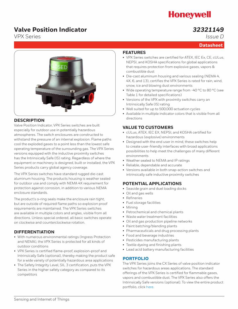
DESCRIPTIONValve Position Indicator, VPX Series switches are built especially for outdoor use in potentially hazardous atmospheres. The switch enclosures are constructed to withstand the pressure of an internal explosion. Flame paths cool the exploded gases to a point less than the lowest safe operating temperature of the surrounding gas. The VPX Series versions equipped with the inductive proximity switches has the Intrinsically Safe (IS) rating. Regardless of where the equipment or machinery is designed, built or installed, the VPX Series products carry global agency coverage.
The VPX Series switches have standard rugged die-cast aluminum housing. The products housing is weather sealed for outdoor use and comply with NEMA 4X requirement for protection against corrosion, in addition to various NEMA enclosure standards.
The product’s o-ring seals make the enclosure rain tight, but are outside of required flame paths so explosion proof requirements are maintained. The VPX Series switches are available in multiple colors and angles, visible from all directions. Unless special ordered, all basic switches operate on clockwise and counterclockwise rotation.
DIFFERENTIATION• With numerous environmental ratings (Ingress Protection
and NEMA), the VPX Series is protected for all kinds of outdoor conditions
• VPX Series is certified flame-proof, explosion-proof and Intrinsically Safe (optional), thereby making the product safe for a wide variety of potentially hazardous area applications
• The Safety Integrity Level, SIL 3 certification, puts the VPX Series in the higher safety category as compared to its competitors
FEATURES• VPX Series switches are certified for ATEX, IEC Ex, CE, cULus,
NEPSI, and KOSHA specifications for global applications that requires protection from explosive gases, vapors & combustible dust
• Die-cast aluminum housing and various sealing (NEMA 4, 4X, 6, and 13), certifies the VPX Series is rated for rain, wind, snow, ice and blowing dust environments
• Wide operating temperature range from -40 °C to 80 °C (see Table 1 for detailed specifications)
• Versions of the VPX with proximity switches carry an Intrinsically Safe (IS) rating
• Well suited for up to 500,000 actuation cycles• Available in multiple indicator colors that is visible from all
directions
VALUE TO CUSTOMERS• cULus, ATEX, IEC EX, NEPSI, and KOSHA certified for
hazardous (explosive) environments • Designed with the end user in mind, these switches help
to create user-friendly interfaces with broad applications possibilities to help meet the challenges of many different environments
• Weather sealed to NEMA and IP ratings• Reliable, dependable and accurate• Versions available in both snap-action switches and
intrinsically safe inductive proximity switches
POTENTIAL APPLICATIONS• Seaside grain and duel loading docks• Oil and gas wells• Refineries• Fuel storage facilities• Mining • Petrochemical and chemical plants• Waste water treatment facilities• Oil and gas production pipeline networks• Paint batching/blending plants• Pharmaceuticals and drug processing plants• Food and beverage industries• Pesticides manufacturing plants• Textile dyeing and finishing plants• Lead acid battery manufacturing facilities
PORTFOLIOThe VPX Series joins the CX Series of valve position indicator switches for hazardous areas applications. The standard offerings of the VPX Series is certified for flammable gases, vapors and combustible dust. The VPX Series also offers the Intrinsically Safe versions (optional). To view the entire product portfolio, click here.
Sensing and Internet of Things
32321149Issue D
2 sensing.honeywell.com
Valve Position Indicator, VPX Series
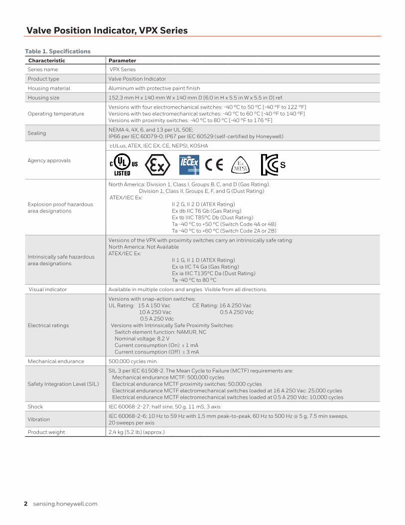
Table 1. SpecificationsCharacteristic Parameter
Series name VPX Series
Product type Valve Position Indicator
Housing material Aluminum with protective paint finish
Housing size 152,3 mm H x 140 mm W x 140 mm D [6.0 in H x 5.5 in W x 5.5 in D] ref.
Operating temperatureVersions with four electromechanical switches: -40 °C to 50 °C [-40 °F to 122 °F]Versions with two electromechanical switches: -40 °C to 60 °C [-40 °F to 140 °F]Versions with proximity switches: -40 °C to 80 °C [-40 °F to 176 °F]
SealingNEMA 4, 4X, 6, and 13 per UL 50E; IP66 per IEC 60079-0; IP67 per IEC 60529 (self-certified by Honeywell)
Agency approvals
cULus, ATEX, IEC EX, CE, NEPSI, KOSHA
Explosion proof hazardous area designations
North America: Division 1, Class I, Groups B, C, and D (Gas Rating) Division 1, Class II, Groups E, F, and G (Dust Rating) ATEX/IEC Ex: II 2 G, II 2 D (ATEX Rating) Ex db IIC T6 Gb (Gas Rating) Ex tb IIIC T85°C Db (Dust Rating) Ta -40 °C to +50 °C (Switch Code 4A or 4B) Ta -40 °C to +60 °C (Switch Code 2A or 2B)
Intrinsically safe hazardous area designations
Versions of the VPX with proximity switches carry an intrinsically safe rating:North America: Not Available ATEX/IEC Ex: II 1 G, II 1 D (ATEX Rating) Ex ia IIC T4 Ga (Gas Rating) Ex ia IIIC T135°C Da (Dust Rating) Ta -40 °C to 80 °C
Visual indicator Available in multiple colors and angles. Visible from all directions.
Electrical ratings
Versions with snap-action switches:UL Rating: 15 A 150 Vac CE Rating: 16 A 250 Vac 10 A 250 Vac 0.5 A 250 Vdc 0.5 A 250 Vdc Versions with Intrinsically Safe Proximity Switches: Switch element function: NAMUR, NC Nominal voltage: 8.2 V Current consumption (On) ≤ 1 mA Current consumption (Off) ≥ 3 mA
Mechanical endurance 500,000 cycles min.
Safety Integration Level (SIL)
SIL 3 per IEC 61508-2. The Mean Cycle to Failure (MCTF) requirements are: Mechanical endurance MCTF: 500,000 cycles Electrical endurance MCTF proximity switches: 50,000 cycles Electrical endurance MCTF electromechanical switches loaded at 16 A 250 Vac: 25,000 cycles Electrical endurance MCTF electromechanical switches loaded at 0.5 A 250 Vdc: 10,000 cycles
Shock IEC 60068-2-27; half sine, 50 g, 11 mS, 3 axis
VibrationIEC 60068-2-6; 10 Hz to 59 Hz with 1,5 mm peak-to-peak, 60 Hz to 500 Hz @ 5 g, 7.5 min sweeps, 20 sweeps per axis
Product weight 2,4 kg [5.2 lb] (approx.)
Sensing and Internet of Things 3
Valve Position Indicator, VPX Series
VPX
Series
1 Aluminum
EnclosureMaterial
1
2A
4A
2X snap actionSPDT
4X snap actionSPDT
SwitchOptions
2A
VPX SeriesValve
PositionIndicator
YB Yellow (open)Black (closed)
GY
RG Red (open)Green (closed)
Green (open)Yellow (closed)
YR
GR
IndicatorColor
China (standard)IEC Ex, ATEX, CE, NEPSI
Origin andCertifications
C
Yellow (open)Red (closed)
2
1 Namur
1/4 in flats
1
ShaftEnd
ConduitEntry
2A
2B2X snap actionSPDT, goldcontacts
4B4X snap actionSPDT, goldcontacts
GR Green (open)Red (closed)
BY Black (open)Yellow (closed)
RY Red (open)Yellow (closed)
YG Yellow (open)Green (closed)
2C2X I.S. inductiveproximityswitch (Namur)
2A
2B
(2) 1/2-14 NPT(A & D)
(2) 3/4-14 NPT(A & D)
2C
2D
(2) M20 x 1.5(A & D)
(2) M25 x 1.5(A & D)
4C (4) M20 x 1.5
(4) M25 x 1.5
3B (3) 3/4-14 NPT(A, B, & D)
4F(2) 1/2-14 NPT(B & D) & (2)3/4-14 NPT (A & D)
4D
AChina (premium)IEC Ex, ATEX, cULus, CE, SIL3,NEPSI, KOSHACUSA (premium)IEC Ex, ATEX, cULus, CE, SIL3,NEPSI, KOSHA
E
A 45°
IndicatorAngle
A
B 90°
3Ø7.25 knurl forex. lever
B
A 360°continuous
±90° withspring return
A
ShaftRotation
– _ _
Specials
Up to twoletters or numbers
to indicate aspecialfeature.1
Leave blankfor no plugs
1 plug
1
Number ofConduit Plugs
3
2 2 plugs
3 plugs
Indicate how manyplugs should be
included. Anyunused conduit entriesmust be sealed with a
blanking element certified to the
hazardous locationenvironment
(or better). Plugs can also be purchased
separately.(see page 7).
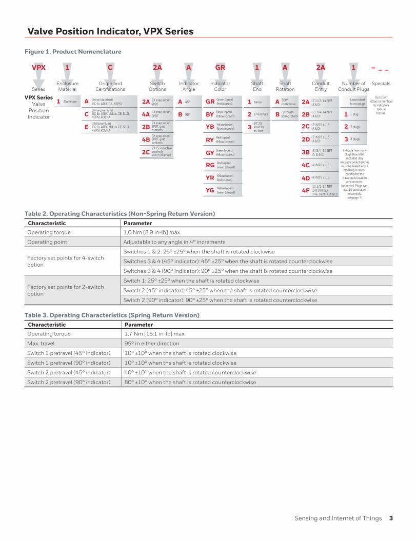
Figure 1. Product Nomenclature
Table 2. Operating Characteristics (Non-Spring Return Version)Characteristic Parameter
Operating torque 1,0 Nm [8.9 in-lb] max.
Operating point Adjustable to any angle in 4° increments
Factory set points for 4-switch option
Switches 1 & 2: 25° ±25° when the shaft is rotated clockwise
Switches 3 & 4 (45° indicator): 45° ±25° when the shaft is rotated counterclockwise
Switches 3 & 4 (90° indicator): 90° ±25° when the shaft is rotated counterclockwise
Factory set points for 2-switch option
Switch 1: 25° ±25° when the shaft is rotated clockwise
Switch 2 (45° indicator): 45° ±25° when the shaft is rotated counterclockwise
Switch 2 (90° indicator): 90° ±25° when the shaft is rotated counterclockwise
Table 3. Operating Characteristics (Spring Return Version)Characteristic Parameter
Operating torque 1,7 Nm [15.1 in-lb] max.
Max. travel 95° in either direction
Switch 1 pretravel (45° indicator) 10° ±10° when the shaft is rotated clockwise
Switch 1 pretravel (90° indicator) 10° ±10° when the shaft is rotated clockwise
Switch 2 pretravel (45° indicator) 40° ±10° when the shaft is rotated counterclockwise
Switch 2 pretravel (90° indicator) 80° ±10° when the shaft is rotated counterclockwise
4 sensing.honeywell.com
Valve Position Indicator, VPX Series
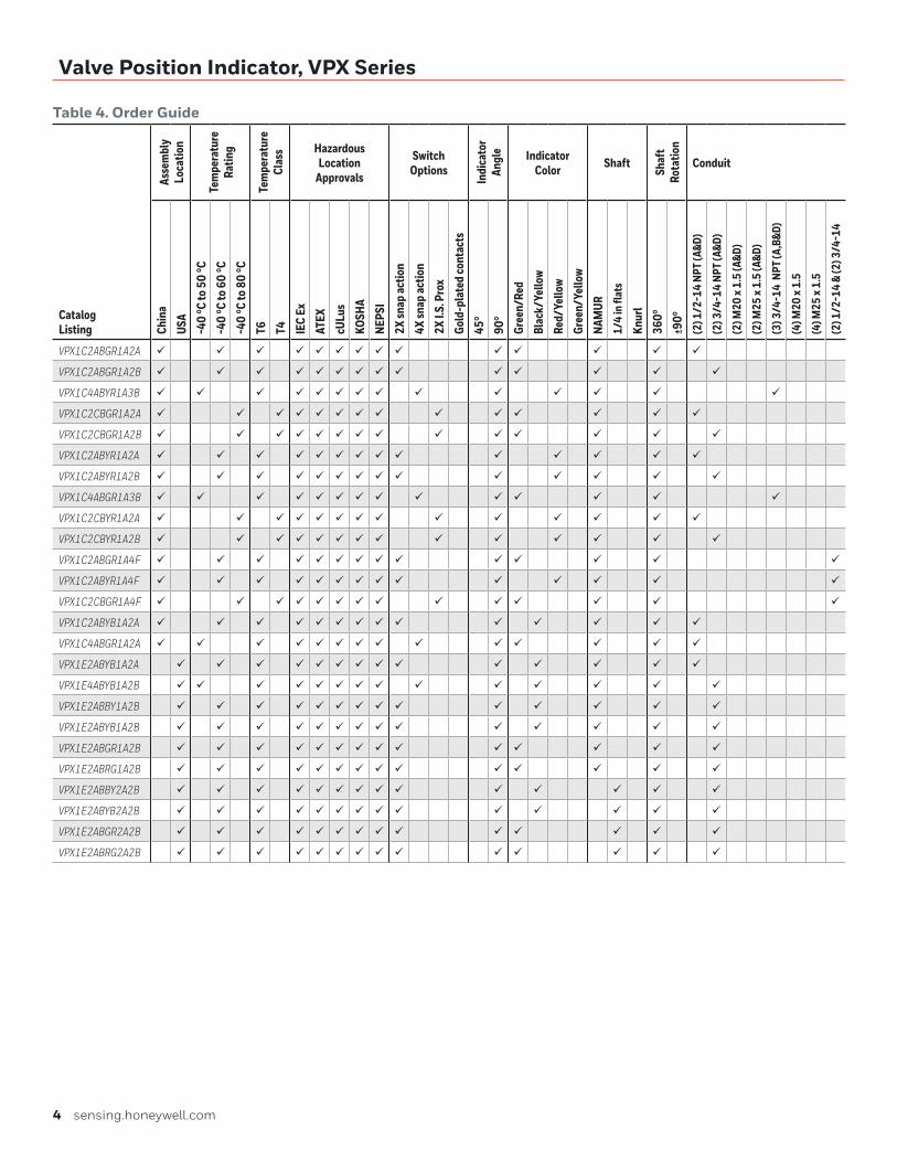
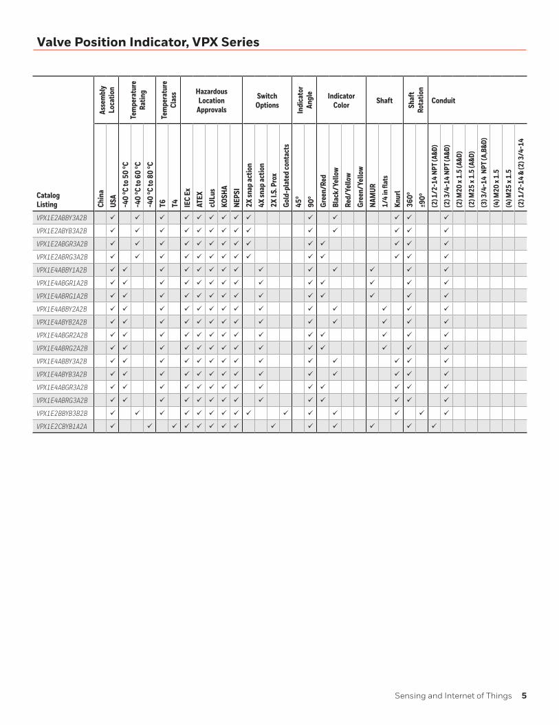
Table 4. Order Guide
Catalog Listing
Asse
mbl
y Lo
catio
n
Tem
pera
ture
Ra
ting
Tem
pera
ture
Cl
ass Hazardous
Location Approvals
Switch Options
Indi
cato
r An
gle Indicator
Color Shaft
Shaf
t Ro
tatio
n
ConduitCh
ina
USA
-40
°C to
50
°C-4
0 °C
to 6
0 °C
-40
°C to
80
°CT6 T4 IE
C Ex
ATEX
cULu
sKO
SHA
NEPS
I2X
snap
actio
n4X
snap
actio
n2X
I.S.
Pro
xGo
ld-p
late
d co
ntac
ts45
°90
°Gr
een/
Red
Blac
k/Ye
llow
Red/
Yello
wGr
een/
Yello
wNA
MUR
1/4
in fl
ats
Knur
l36
0°±9
0°(2
) 1/2
-14
NPT
(A&D
)
(2) 3
/4-1
4 NP
T (A
&D)
(2) M
20 x
1.5
(A&D
)
(2) M
25 x
1.5
(A&D
)
(3) 3
/4-1
4 N
PT (A
,B&D
)
(4) M
20 x
1.5
(4) M
25 x
1.5
(2) 1
/2-1
4 &
(2) 3
/4-1
4
VPX1C2ABGR1A2A ü ü ü ü ü ü ü ü ü ü ü ü ü ü
VPX1C2ABGR1A2B ü ü ü ü ü ü ü ü ü ü ü ü ü ü
VPX1C4ABYR1A3B ü ü ü ü ü ü ü ü ü ü ü ü ü ü
VPX1C2CBGR1A2A ü ü ü ü ü ü ü ü ü ü ü ü ü ü
VPX1C2CBGR1A2B ü ü ü ü ü ü ü ü ü ü ü ü ü ü
VPX1C2ABYR1A2A ü ü ü ü ü ü ü ü ü ü ü ü ü ü
VPX1C2ABYR1A2B ü ü ü ü ü ü ü ü ü ü ü ü ü ü
VPX1C4ABGR1A3B ü ü ü ü ü ü ü ü ü ü ü ü ü ü
VPX1C2CBYR1A2A ü ü ü ü ü ü ü ü ü ü ü ü ü ü
VPX1C2CBYR1A2B ü ü ü ü ü ü ü ü ü ü ü ü ü ü
VPX1C2ABGR1A4F ü ü ü ü ü ü ü ü ü ü ü ü ü ü
VPX1C2ABYR1A4F ü ü ü ü ü ü ü ü ü ü ü ü ü ü
VPX1C2CBGR1A4F ü ü ü ü ü ü ü ü ü ü ü ü ü ü
VPX1C2ABYB1A2A ü ü ü ü ü ü ü ü ü ü ü ü ü ü
VPX1C4ABGR1A2A ü ü ü ü ü ü ü ü ü ü ü ü ü ü
VPX1E2ABYB1A2A ü ü ü ü ü ü ü ü ü ü ü ü ü ü
VPX1E4ABYB1A2B ü ü ü ü ü ü ü ü ü ü ü ü ü ü
VPX1E2ABBY1A2B ü ü ü ü ü ü ü ü ü ü ü ü ü ü
VPX1E2ABYB1A2B ü ü ü ü ü ü ü ü ü ü ü ü ü ü
VPX1E2ABGR1A2B ü ü ü ü ü ü ü ü ü ü ü ü ü ü
VPX1E2ABRG1A2B ü ü ü ü ü ü ü ü ü ü ü ü ü ü
VPX1E2ABBY2A2B ü ü ü ü ü ü ü ü ü ü ü ü ü ü
VPX1E2ABYB2A2B ü ü ü ü ü ü ü ü ü ü ü ü ü ü
VPX1E2ABGR2A2B ü ü ü ü ü ü ü ü ü ü ü ü ü ü
VPX1E2ABRG2A2B ü ü ü ü ü ü ü ü ü ü ü ü ü ü
Sensing and Internet of Things 5
Valve Position Indicator, VPX Series
Catalog Listing
Asse
mbl
y Lo
catio
n
Tem
pera
ture
Ra
ting
Tem
pera
ture
Cl
ass Hazardous
Location Approvals
Switch Options
Indi
cato
r An
gle Indicator
Color Shaft
Shaf
t Ro
tatio
n
ConduitCh
ina
USA
-40
°C to
50
°C-4
0 °C
to 6
0 °C
-40
°C to
80
°CT6 T4 IE
C Ex
ATEX
cULu
sKO
SHA
NEPS
I2X
snap
actio
n4X
snap
actio
n2X
I.S.
Pro
xGo
ld-p
late
d co
ntac
ts45
°90
°Gr
een/
Red
Blac
k/Ye
llow
Red/
Yello
wGr
een/
Yello
wNA
MUR
1/4
in fl
ats
Knur
l36
0°±9
0°(2
) 1/2
-14
NPT
(A&D
)
(2) 3
/4-1
4 NP
T (A
&D)
(2) M
20 x
1.5
(A&D
)
(2) M
25 x
1.5
(A&D
)
(3) 3
/4-1
4 N
PT (A
,B&D
)
(4) M
20 x
1.5
(4) M
25 x
1.5
(2) 1
/2-1
4 &
(2) 3
/4-1
4
VPX1E2ABBY3A2B ü ü ü ü ü ü ü ü ü ü ü ü ü ü
VPX1E2ABYB3A2B ü ü ü ü ü ü ü ü ü ü ü ü ü ü
VPX1E2ABGR3A2B ü ü ü ü ü ü ü ü ü ü ü ü ü ü
VPX1E2ABRG3A2B ü ü ü ü ü ü ü ü ü ü ü ü ü ü
VPX1E4ABBY1A2B ü ü ü ü ü ü ü ü ü ü ü ü ü ü
VPX1E4ABGR1A2B ü ü ü ü ü ü ü ü ü ü ü ü ü ü
VPX1E4ABRG1A2B ü ü ü ü ü ü ü ü ü ü ü ü ü ü
VPX1E4ABBY2A2B ü ü ü ü ü ü ü ü ü ü ü ü ü ü
VPX1E4ABYB2A2B ü ü ü ü ü ü ü ü ü ü ü ü ü ü
VPX1E4ABGR2A2B ü ü ü ü ü ü ü ü ü ü ü ü ü ü
VPX1E4ABRG2A2B ü ü ü ü ü ü ü ü ü ü ü ü ü ü
VPX1E4ABBY3A2B ü ü ü ü ü ü ü ü ü ü ü ü ü ü
VPX1E4ABYB3A2B ü ü ü ü ü ü ü ü ü ü ü ü ü ü
VPX1E4ABGR3A2B ü ü ü ü ü ü ü ü ü ü ü ü ü ü
VPX1E4ABRG3A2B ü ü ü ü ü ü ü ü ü ü ü ü ü ü
VPX1E2BBYB3B2B ü ü ü ü ü ü ü ü ü ü ü ü ü ü ü
VPX1E2CBYB1A2A ü ü ü ü ü ü ü ü ü ü ü ü ü ü
6 sensing.honeywell.com
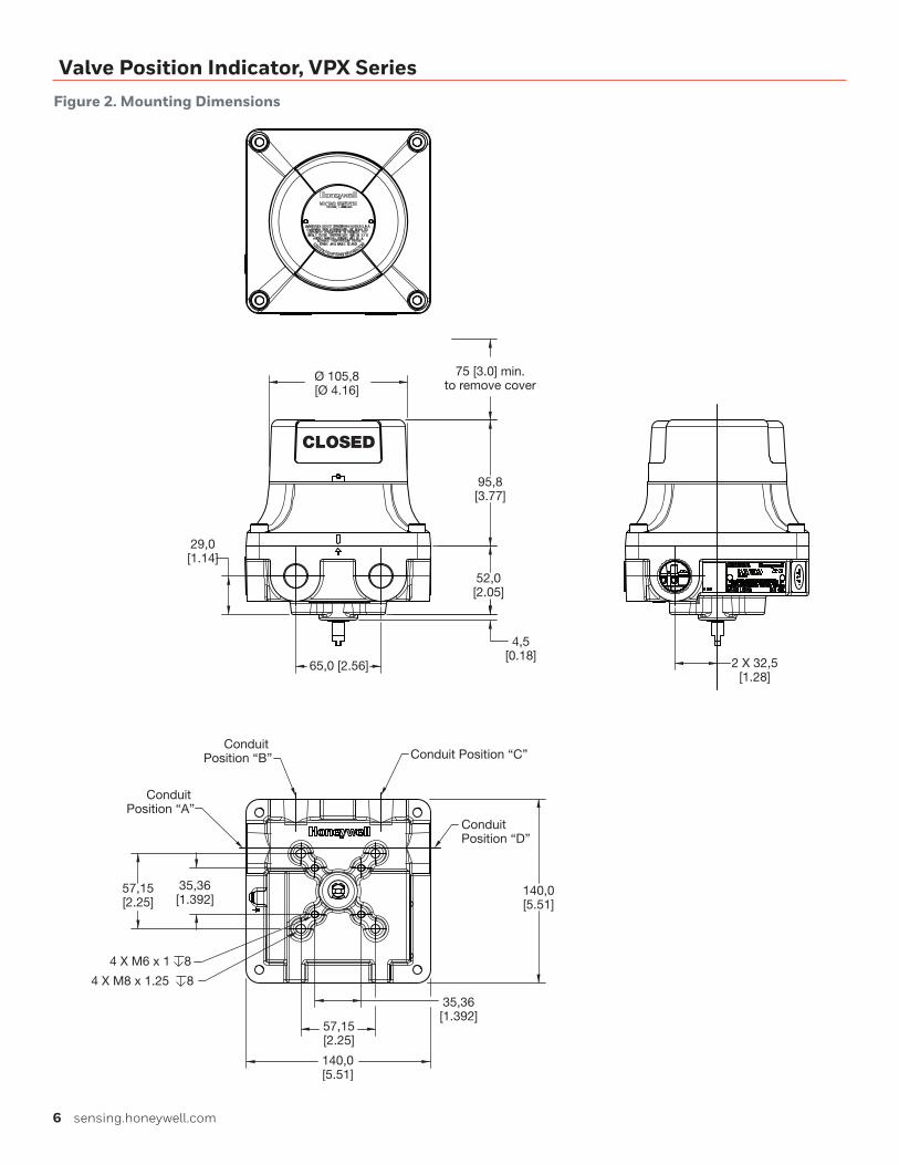
Valve Position Indicator, VPX SeriesFigure 2. Mounting Dimensions
CLOSED
75 [3.0] min.to remove cover
95,8[3.77]
Ø 105,8[Ø 4.16]
52,0[2.05]
4,5[0.18]
2 X 32,5[1.28]
65,0 [2.56]
29,0[1.14]
140,0[5.51]
Conduit Position “C”
Conduit Position “D”
Conduit Position “B”
Conduit Position “A”
35,36[1.392]
140,0[5.51]
57,15[2.25]
57,15[2.25]
35,36[1.392]
4 X M6 x 1 8
4 X M8 x 1.25 8
Sensing and Internet of Things 7
Valve Position Indicator, VPX Series
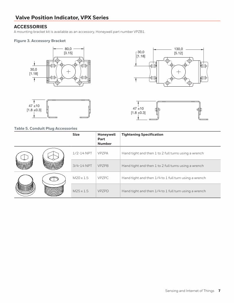
ACCESSORIESA mounting bracket kit is available as an accessory, Honeywell part number VPZB1.
Figure 3. Accessory Bracket
80,0[3.15]
30,0[1.18]
30,0[1.18]
130,0[5.12]
47 ±10[1.8 ±0.3] 47 ±10
[1.8 ±0.3]
Table 5. Conduit Plug AccessoriesSize Honeywell
Part Number
Tightening Specification
1/2-14 NPT VPZPA Hand tight and then 1 to 2 full turns using a wrench
3/4-14 NPT VPZPB Hand tight and then 1 to 2 full turns using a wrench
M20 x 1.5 VPZPC Hand tight and then 1/4 to 1 full turn using a wrench
M25 x 1.5 VPZPD Hand tight and then 1/4 to 1 full turn using a wrench
8 sensing.honeywell.com
Valve Position Indicator, VPX Series
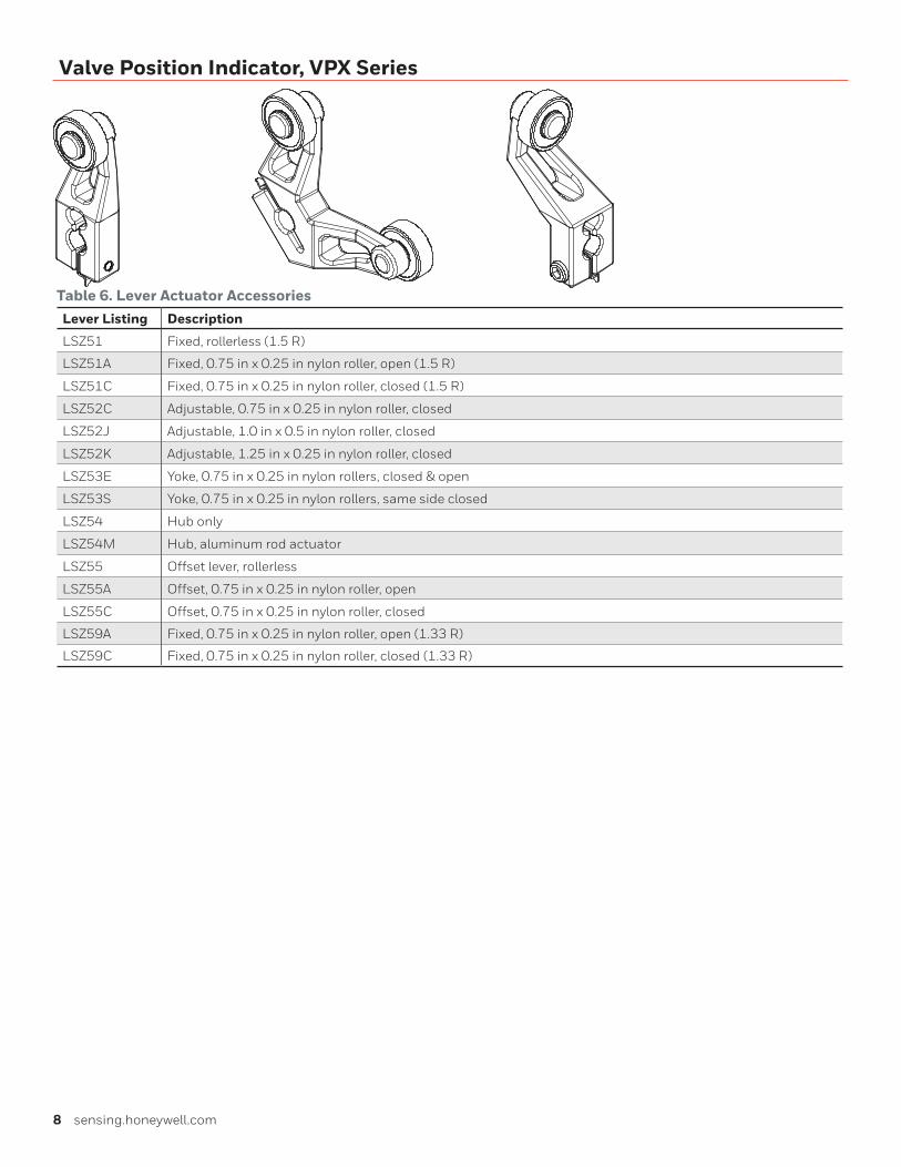
Table 6. Lever Actuator AccessoriesLever Listing Description
LSZ51 Fixed, rollerless (1.5 R)
LSZ51A Fixed, 0.75 in x 0.25 in nylon roller, open (1.5 R)
LSZ51C Fixed, 0.75 in x 0.25 in nylon roller, closed (1.5 R)
LSZ52C Adjustable, 0.75 in x 0.25 in nylon roller, closed
LSZ52J Adjustable, 1.0 in x 0.5 in nylon roller, closed
LSZ52K Adjustable, 1.25 in x 0.25 in nylon roller, closed
LSZ53E Yoke, 0.75 in x 0.25 in nylon rollers, closed & open
LSZ53S Yoke, 0.75 in x 0.25 in nylon rollers, same side closed
LSZ54 Hub only
LSZ54M Hub, aluminum rod actuator
LSZ55 Offset lever, rollerless
LSZ55A Offset, 0.75 in x 0.25 in nylon roller, open
LSZ55C Offset, 0.75 in x 0.25 in nylon roller, closed
LSZ59A Fixed, 0.75 in x 0.25 in nylon roller, open (1.33 R)
LSZ59C Fixed, 0.75 in x 0.25 in nylon roller, closed (1.33 R)
Warranty/RemedyHoneywell warrants goods of its manufacture as being free of defective materials and faulty workmanship during the appli-cable warranty period. Honeywell’s standard product warranty applies unless agreed to otherwise by Honeywell in writing; please refer to your order acknowledgment or consult your local sales office for specific warranty details. If warranted goods are returned to Honeywell during the period of coverage, Honeywell will repair or replace, at its option, without charge those items that Honeywell, in its sole discretion, finds defec-tive. The foregoing is buyer’s sole remedy and is in lieu of all other warranties, expressed or implied, including those of merchantability and fitness for a particular purpose. In no event shall Honeywell be liable for consequential, special, or indirect damages.
While Honeywell may provide application assistance personally, through our literature and the Honeywell web site, it is buyer’s sole responsibility to determine the suitability of the product in the application.
Specifications may change without notice. The information we supply is believed to be accurate and reliable as of this writing. However, Honeywell assumes no responsibility for its use.
32321149-D-EN IL50 GLO February 2017© 2017 Honeywell International Inc. All rights reserved.
m WARNINGPERSONAL INJURYDO NOT USE these products as safety or emergency stop devices or in any other application where failure of the product could result in personal injury.
Failure to comply with these instructions could result in death or serious injury.
m WARNINGMISUSE OF DOCUMENTATION• The information presented in this product sheet is for
reference only. Do not use this document as a product installation guide.
• Complete installation, operation, and maintenance information is provided in the instructions supplied with each product.
Failure to comply with these instructions could result in death or serious injury.
Find out moreHoneywell serves its customers
through a worldwide network
of sales offices, representatives
and distributors. For applica-
tion assistance, current specifi-
cations, pricing or name of the
nearest Authorized Distributor,
contact your local sales office.
To learn more about Honey-
well’s sensing and switching
products,
call +1-815-235-6847 or 1-800-537-6945, visit sensing.honeywell.com, or e-mail inquiries to
ADDITIONAL MATERIALSThe following associated literature is available at sensing.honeywell.com:
• Product range guide
• Installation instructions
• Application note
Honeywell Sensing and Internet of Things9680 Old Bailes Road
Fort Mill, SC 29707
honeywell.com