vantage remote access software manual - interprovincial remote access... · vantage remote access...
TRANSCRIPT
© 2007 Iteris Inc.
Vantage Remote Access Software
ManualNovember 2007
493076301 Rev B
The VRAS Help File2
© 2007 Iteris Inc.
Table of Contents
Part I Welcome To VRAS 5
Part II Legal Notices 6
Part III VRAS Requirements 7
................................................................................................................................... 81 Computer
................................................................................................................................... 92 Dial-up Modems
................................................................................................................................... 103 File Transfer Cable
................................................................................................................................... 114 Current Vantage Firmware
Part IV Connection Methods 12
................................................................................................................................... 131 Direct Connection
................................................................................................................................... 142 Modem Connection
................................................................................................................................... 153 Fiber Connection
................................................................................................................................... 164 Multi drop Connection
.......................................................................................................................................................... 16Multi drop Addressing
.......................................................................................................................................................... 17Multi drop Cable
Part V Quick Start 18
................................................................................................................................... 191 Creating a Site
................................................................................................................................... 202 Connecting to a Site
Part VI VRAS Walk Through 22
................................................................................................................................... 231 Start-up Screen - Main
.......................................................................................................................................................... 23File
.......................................................................................................................................................... 24Help
.......................................................................................................................................................... 25Remote Access
.......................................................................................................................................................... 25Off-Line Configuration
.......................................................................................................................................................... 27Exit
................................................................................................................................... 282 Site List Screen
.......................................................................................................................................................... 29Connect
.......................................................................................................................................................... 30Edit Site Info
......................................................................................................................................................... 30Add
......................................................................................................................................................... 31Edit
......................................................................................................................................................... 31Remove
......................................................................................................................................................... 31Cancel
......................................................................................................................................................... 31Save
.......................................................................................................................................................... 31Main Menu
................................................................................................................................... 323 General Status Screen
.......................................................................................................................................................... 34Detection Status Screens
......................................................................................................................................................... 34Detection Status
3Contents
3
© 2007 Iteris Inc.
......................................................................................................................................................... 35TS2-IM Status
......................................................................................................................................................... 36IOM-32 Status
.......................................................................................................................................................... 37Video
......................................................................................................................................................... 38Acquire Snapshot
......................................................................................................................................................... 38Load Snapshot
......................................................................................................................................................... 39Save Snapshot
......................................................................................................................................................... 39Start Continuous Mode
......................................................................................................................................................... 39Update Channel Status
......................................................................................................................................................... 39Save Snapshots to File
.......................................................................................................................................................... 40Zone Setup Screen
......................................................................................................................................................... 42Acquire Snapshot
......................................................................................................................................................... 42Load Snapshot
......................................................................................................................................................... 42Video Transfer
......................................................................................................................................................... 43System Labels
......................................................................................................................................................... 43Zone Labels
......................................................................................................................................................... 44Zone Controls
......................................................................................................................................................... 46Zone Configuration Information
......................................................................................................................................................... 48Save Snapshot
......................................................................................................................................................... 48Save Snapshot With Zones
......................................................................................................................................................... 48Retrieve Configuration From Processor
......................................................................................................................................................... 48Load Configuration From Disk
......................................................................................................................................................... 48Send Configuration to Processor
......................................................................................................................................................... 49Save Configuration to Disk
......................................................................................................................................................... 49Clone Configuration
......................................................................................................................................................... 50TOD Schedule
......................................................................................................................................................... 51Zone Color
......................................................................................................................................................... 52Special LC Output
......................................................................................................................................................... 52View Zone Calls
......................................................................................................................................................... 52Sensitivity
......................................................................................................................................................... 52Option
......................................................................................................................................................... 52Glare Output Channel
......................................................................................................................................................... 53Vlock Output Channel
.......................................................................................................................................................... 54Retrieve MOE Data
......................................................................................................................................................... 55Bin Reset
......................................................................................................................................................... 55Bin All
......................................................................................................................................................... 56Bin Last
......................................................................................................................................................... 56Bin New
......................................................................................................................................................... 56Bin Today
......................................................................................................................................................... 56Bin Yesterday
......................................................................................................................................................... 56Terminate Bin Data Dump
......................................................................................................................................................... 57Set Bin Interval
......................................................................................................................................................... 57Clear Display
......................................................................................................................................................... 58Saving Data
.......................................................................................................................................................... 59Utilities Screen
......................................................................................................................................................... 60Reset Processor
......................................................................................................................................................... 60Assign Unit ID
......................................................................................................................................................... 61Reset Extension Module
......................................................................................................................................................... 61Set Time
......................................................................................................................................................... 62Sync to PC Clock
......................................................................................................................................................... 62Reset Zone
......................................................................................................................................................... 63Set Inactive Channel
......................................................................................................................................................... 63Set Max Recall
......................................................................................................................................................... 64Timestamp Overlay Display
......................................................................................................................................................... 64Display Counts Overlay

The VRAS Help File4
© 2007 Iteris Inc.
......................................................................................................................................................... 65Video Output On/Off
......................................................................................................................................................... 65Output Overlay On/Off
......................................................................................................................................................... 65Switch Video Output (Access)
......................................................................................................................................................... 68Switch Video Output
......................................................................................................................................................... 68Set Display Mode
......................................................................................................................................................... 69TOD Schedule On/Off
......................................................................................................................................................... 70LC Threshold
......................................................................................................................................................... 71Run New Configuration
................................................................................................................................... 724 Entry Editor Screen
.......................................................................................................................................................... 73Data File Name
.......................................................................................................................................................... 73Save
.......................................................................................................................................................... 73Cancel
.......................................................................................................................................................... 74General Tab
.......................................................................................................................................................... 75TCP/IP Tab
.......................................................................................................................................................... 76Serial Tab
......................................................................................................................................................... 77Modem
Part VII Using VRAS With The Vantage Viewer 78
Part VIII Troubleshooting 80
Part IX Other References 83
Part X Product Support Contact Information 84
Index 85
Welcome To VRAS 5
© 2007 Iteris Inc.
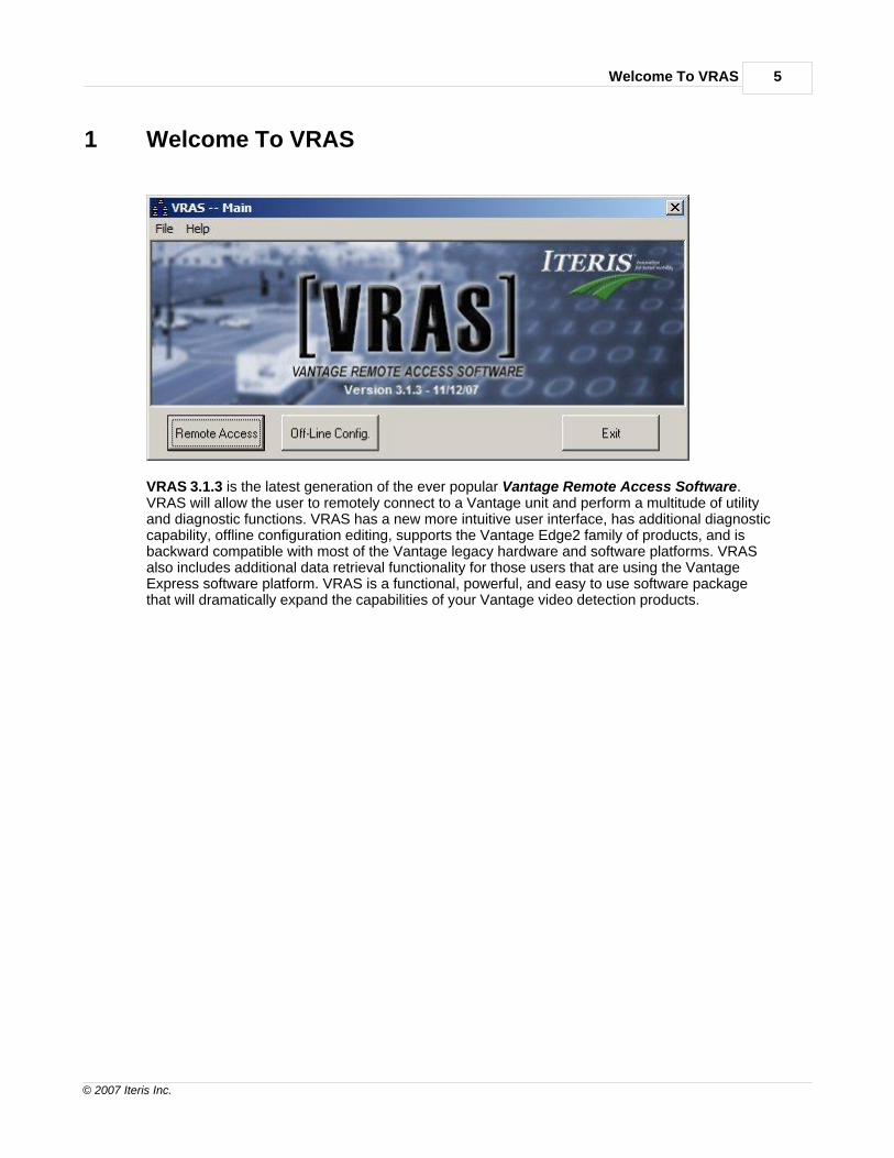
1 Welcome To VRAS
VRAS 3.1.3 is the latest generation of the ever popular Vantage Remote Access Software.VRAS will allow the user to remotely connect to a Vantage unit and perform a multitude of utilityand diagnostic functions. VRAS has a new more intuitive user interface, has additional diagnosticcapability, offline configuration editing, supports the Vantage Edge2 family of products, and isbackward compatible with most of the Vantage legacy hardware and software platforms. VRASalso includes additional data retrieval functionality for those users that are using the VantageExpress software platform. VRAS is a functional, powerful, and easy to use software packagethat will dramatically expand the capabilities of your Vantage video detection products.

The VRAS Help File6
© 2007 Iteris Inc.
2 Legal Notices
Copyright January 2007 Iteris Inc. All rights reserved.
Legal Notice:No parts of this work may be reproduced in any form or by any means - graphic,electronic, or mechanical, including photocopying, recording, taping, or information storage andretrieval systems - without the written permission of Iteris Inc.
Iteris provides this publication "as is" without warranty of any kind, either express or implied,including but not limited to the implied warranties of merchantability or fitness for a particularpurpose. Iteris may revise this publication from time to time without notice.
Products that are referred to in this document may be either trademarks and/or registered trademarksof the respective owners. The publisher and the author make no claim to these trademarks.

VRAS Requirements 7
© 2007 Iteris Inc.
3 VRAS Requirements
See the following important subtopics for details on the VRAS requirements for these items:
Computer
Dial-up Modem
Serial File Transfer Cable
Vantage Firmware Version

The VRAS Help File8
© 2007 Iteris Inc.
3.1 Computer
To use VRAS, it is necessary that the user have a notebook or desktop computer systemthat meets the following minimum requirements:
· You must be using a Pentium class computer (200 MHz or better) · You must have at least 64 MB of RAM (128MB Recommended) · You will need a VGA color monitor · The Vantage unit requires a Vantage compatible PS/2 serial or USB three button mouse · You must have at least 10 MB free disk space available on hard drive
You may need more space if you have lots of saved images.
· You should be running Windows 95/98, ME, 2000, NT, or XP as your operating system · You will need a Vantage Serial Crossover Cable (for direct connection) See the help file documentation for the correct Vantage VRAS Serial Cable Configuration · You will require a Vantage Multi-drop Cable for Multi drop applications See the help file documentation for Vantage Multi-drop Cable information · You will need a 56K modem for optimal performance on a dial up connection · You should be running the latest Vantage firmware version to take advantage of all the
latest features that are now available.

VRAS Requirements 9
© 2007 Iteris Inc.
3.2 Dial-up Modems
The U.S. Robotics modems are recommended by Iteris, due to their use of external configurationDIP switches, which allow ease of configuration for use with your Vantage hardware and software.Other internal or external modems can be used, and most likely will work, however, configurationmay be slightly more difficult. Slower modems can also be used, but performance will becompromised accordingly.
USR 56K V.92 External Fax modem
Please see the section on modem connection and setup information for more details.
The VRAS Help File10
© 2007 Iteris Inc.
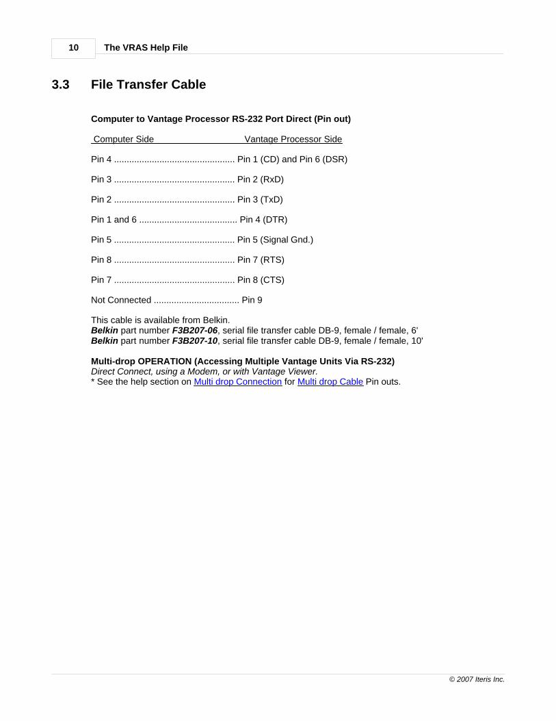
3.3 File Transfer Cable
Computer to Vantage Processor RS-232 Port Direct (Pin out)
Computer Side Vantage Processor Side
Pin 4 ................................................ Pin 1 (CD) and Pin 6 (DSR)
Pin 3 ................................................ Pin 2 (RxD)
Pin 2 ................................................ Pin 3 (TxD)
Pin 1 and 6 ....................................... Pin 4 (DTR)
Pin 5 ................................................ Pin 5 (Signal Gnd.)
Pin 8 ................................................ Pin 7 (RTS)
Pin 7 ................................................ Pin 8 (CTS)
Not Connected .................................. Pin 9
This cable is available from Belkin.Belkin part number F3B207-06, serial file transfer cable DB-9, female / female, 6'Belkin part number F3B207-10, serial file transfer cable DB-9, female / female, 10'
Multi-drop OPERATION (Accessing Multiple Vantage Units Via RS-232)Direct Connect, using a Modem, or with Vantage Viewer.* See the help section on Multi drop Connection for Multi drop Cable Pin outs.

VRAS Requirements 11
© 2007 Iteris Inc.
3.4 Current Vantage Firmware
To use VRAS, the Vantage hardware should be using the latest Vantage firmware to benefit from al the new features and functions.
Check the Vantage equipment to make sure that it is using the latest Vantage firmware.See the list below to see which firmware versions can be used with VRAS 3.1.3.
Vantage One v1.16SP1 orLater
Vantage Plus v1.16SP1 orLater
Vantage Edge v1.16SP1 orLater
Vantage Edge2-1and 2-2 v1.13 or Later
Express (One) v2.18 or Later
Vantage Edge2-4 v1.13 or Later
Vantage Edge2-2 Express v2.04 or Later
Vantage Access v1.13 or Later
Vantage eAccess v1.13 or Later

The VRAS Help File12
© 2007 Iteris Inc.
4 Connection Methods
The following subtopics are covered in this section:
Direct Connect
Via Modem
Via Fiber
Multi drop
* Multi drop operation requires use of special Multi-drop Serial Communication Cable.See the section on the Vantage Multi drop Cable.
Connection Methods 13
© 2007 Iteris Inc.
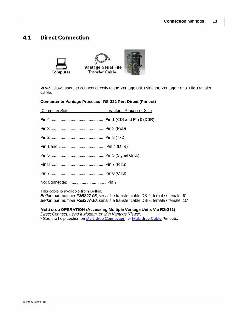
4.1 Direct Connection
VRAS allows users to connect directly to the Vantage unit using the Vantage Serial File TransferCable.
Computer to Vantage Processor RS-232 Port Direct (Pin out)
Computer Side Vantage Processor Side
Pin 4 ................................................ Pin 1 (CD) and Pin 6 (DSR)
Pin 3 ................................................ Pin 2 (RxD)
Pin 2 ................................................ Pin 3 (TxD)
Pin 1 and 6 ....................................... Pin 4 (DTR)
Pin 5 ................................................ Pin 5 (Signal Gnd.)
Pin 8 ................................................ Pin 7 (RTS)
Pin 7 ................................................ Pin 8 (CTS)
Not Connected .................................. Pin 9
This cable is available from Belkin.Belkin part number F3B207-06, serial file transfer cable DB-9, female / female, 6'Belkin part number F3B207-10, serial file transfer cable DB-9, female / female, 10'
Multi drop OPERATION (Accessing Multiple Vantage Units Via RS-232)Direct Connect, using a Modem, or with Vantage Viewer.* See the help section on Multi drop Connection for Multi drop Cable Pin outs.
The VRAS Help File14
© 2007 Iteris Inc.
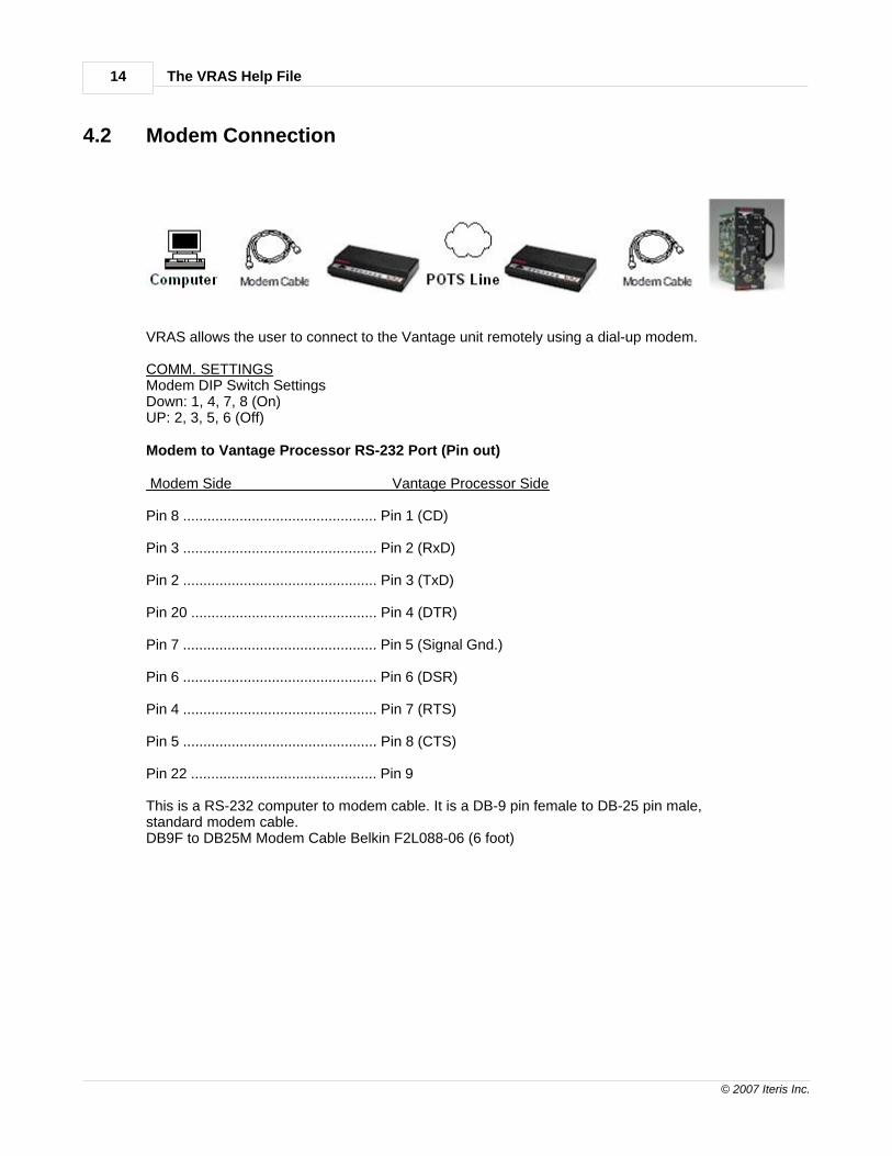
4.2 Modem Connection
VRAS allows the user to connect to the Vantage unit remotely using a dial-up modem.
COMM. SETTINGSModem DIP Switch SettingsDown: 1, 4, 7, 8 (On)UP: 2, 3, 5, 6 (Off)
Modem to Vantage Processor RS-232 Port (Pin out)
Modem Side Vantage Processor Side
Pin 8 ................................................ Pin 1 (CD)
Pin 3 ................................................ Pin 2 (RxD)
Pin 2 ................................................ Pin 3 (TxD)
Pin 20 .............................................. Pin 4 (DTR)
Pin 7 ................................................ Pin 5 (Signal Gnd.)
Pin 6 ................................................ Pin 6 (DSR)
Pin 4 ................................................ Pin 7 (RTS)
Pin 5 ................................................ Pin 8 (CTS)
Pin 22 .............................................. Pin 9
This is a RS-232 computer to modem cable. It is a DB-9 pin female to DB-25 pin male,standard modem cable.DB9F to DB25M Modem Cable Belkin F2L088-06 (6 foot)

Connection Methods 15
© 2007 Iteris Inc.
4.3 Fiber Connection
Computer Comm Port DB-9 To Fiber ModemPin 2 Receive Data Data OutPin 3 Transmit Data Data InPin 5 Ground Ground
Fiber Modem To Vantage Unit DB-9 Serial PortData Out Pin 2 Receive DataData In Pin 3 Transmit DataGround Pin 5 Ground
Vantage units can also be connected using fiber modems to transmit video and bi-directionalRS-232 data. Call your local Vantage Dealer or the Iteris Factory Product Support Team fortechnical information on specific fiber modem applications.
Note: The picture and table above show two methods of connection, however, depending on theapplication, the modem manufacturer, and the fiber modem model; the connections shown maynot always be the correct choice. Check the fiber modem manufacturers documentation forinstallation information to determine what type of cable or connections need to be made.

The VRAS Help File16
© 2007 Iteris Inc.
4.4 Multi drop Connection
The Vantage units are capable of Multi-drop operation using the proper Vantage Multi-drop cableconfiguration.See the section on Vantage Multi-drop Cable for more details on mutlidrop configuration.
4.4.1 Multi drop Addressing
What is Multi drop? It is the ability of the Vantage units to be daisy chained together via their RS-232ports and to be accessed individually, using VRAS, by a uniquely assigned Unit ID.In order to take advantage of the Vantage Multi drop capability the user must be running firmwareversion 1.09 or higher in conjunction with VRAS 3.1.3.Edge2 should be running firmware v1.02 or higher.
One of the following Multi drop cables will be required depending upon the application:CABLE A for multi-drop use with the Vantage Viewer or Computer.CABLE B for multi-drop use with a modem.
Refer to the section on Multi drop to determine which cable you will need or simply jump to theMulti-drop Cable help section for detailed cable information and cable pin outs.
All Unit ID's must be unique in each Vantage unit on the Multi drop chain.
REMEMBER: If you are using the Vantage Viewer with VRAS make sure you Check (enable) the box"Viewer (via IPC)" in the Entry Editor Dialog screen on the General Tab.
Connection Methods 17
© 2007 Iteris Inc.
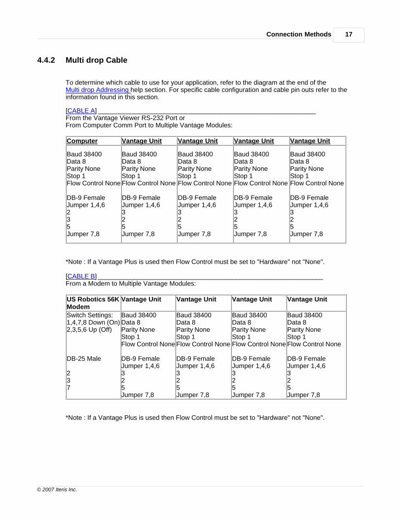
4.4.2 Multi drop Cable
To determine which cable to use for your application, refer to the diagram at the end of theMulti drop Addressing help section. For specific cable configuration and cable pin outs refer to theinformation found in this section.
[CABLE A] ____________________________________________________________From the Vantage Viewer RS-232 Port orFrom Computer Comm Port to Multiple Vantage Modules:
Computer Vantage Unit Vantage Unit Vantage Unit Vantage Unit
Baud 38400Data 8Parity NoneStop 1Flow Control None
DB-9 FemaleJumper 1,4,6235Jumper 7,8
Baud 38400Data 8Parity NoneStop 1Flow Control None
DB-9 FemaleJumper 1,4,6325Jumper 7,8
Baud 38400Data 8Parity NoneStop 1Flow Control None
DB-9 FemaleJumper 1,4,6325Jumper 7,8
Baud 38400Data 8Parity NoneStop 1Flow Control None
DB-9 FemaleJumper 1,4,6325Jumper 7,8
Baud 38400Data 8Parity NoneStop 1Flow Control None
DB-9 FemaleJumper 1,4,6325Jumper 7,8
*Note : If a Vantage Plus is used then Flow Control must be set to "Hardware" not "None".
[CABLE B] ______________________________________________________________From a Modem to Multiple Vantage Modules:
US Robotics 56KModem
Vantage Unit Vantage Unit Vantage Unit Vantage Unit
Switch Settings:1,4,7,8 Down (On)2,3,5,6 Up (Off)
DB-25 Male
237
Baud 38400Data 8Parity NoneStop 1Flow Control None
DB-9 FemaleJumper 1,4,6325Jumper 7,8
Baud 38400Data 8Parity NoneStop 1Flow Control None
DB-9 FemaleJumper 1,4,6325Jumper 7,8
Baud 38400Data 8Parity NoneStop 1Flow Control None
DB-9 FemaleJumper 1,4,6325Jumper 7,8
Baud 38400Data 8Parity NoneStop 1Flow Control None
DB-9 FemaleJumper 1,4,6325Jumper 7,8
*Note : If a Vantage Plus is used then Flow Control must be set to "Hardware" not "None".
The VRAS Help File18
© 2007 Iteris Inc.
5 Quick Start
If you just want to learn how to quickly create a site, direct connect from your computer toyour Vantage unit, and to accomplish this without having to read all the details; then thisnext section will be especially for you.
Quick Start
Creating a Site and Setting Communication Parameters
Selecting a Site and Connecting to it

Quick Start 19
© 2007 Iteris Inc.
5.1 Creating a Site
1) Start VRAS . Press the button on the "Main" VRAS Dialog Screen.2) Connect the Serial File Transfer Cable from your computer to the Vantage units RS-232 port.
3) Now you will need to create a New Site. Press the button on the VRAS"Remote Access" Dialog Screen.
4) Press the button on the VRAS "Edit Poll List" Dialog Screen.This will bring up the "Entry Editor". Make sure the "General" tab is selected.We will be setting up a sample site for Direct Connection to a Vantage unit. For setting upother types of sites refer to the more detailed sections on the type of site and communicationthat you require.5) Type in a "Site Description" in the appropriate text box. The site description identifies the sitethat we are about to create. The Site Description can be an intersection name like Katella & Mainor it can be more of a description of the type of connection like TCP_IP_001 or it could be somecombination of both, the choice is completely up to the user.6) The "Unit ID" is the address that will be used to access the Vantage unit. Unless you are usingMulti-drop operation we recommend you leave this as the factory default of "0000".7) For our purposes in this example we will be using a direct or serial connection via aSerial File Transfer Cable. Make sure the Serial method is selected as shown below.
8) Ignore the "Data File Name" for now, we will be covering that option in detail later on.
Select the "Serial" tab. Select the appropriate "Serial Port"(Usually "1"). Select a "Data Rate". The default setting in the Vantage processors is38400 and that is the recommended setting for most applications."Flow Control" should be set to "RTS/CTS" which is hardware flow control.Leave the "Use With Dial-up Modem" box unselected, since we will be direct connectingin this example.
9) Press the button on the "Entry Editor" dialog screen. Then press "Save"again on the "Edit Poll List" dialog screen. Congratulations! You have just created a newsite. It will now show up as a valid choice in your list of sites.

The VRAS Help File20
© 2007 Iteris Inc.
IMPORTANT NOTE: The communication parameters set in VRAS must match the communicationparameters that are set in the Vantage unit under the "Mode" menu. If they do not match, thencommunication between the Vantage unit and the VRAS software will not be possible. Always checkand verify these settings are the same.
5.2 Connecting to a Site
After you have created a site, as described in the previous section, "Creating a Site",you can now use that site to connect to a Vantage unit.
1) Select the desired site from the list of sites on the "Remote Access" dialog screen.It will be highlighted when the site is actually selected.
2) Then, press the button. You should now see the "Site" dialog screenbeing displayed with the General Status of the Vantage unit.

Quick Start 21
© 2007 Iteris Inc.
See the section on the General Status Screen for more information.

The VRAS Help File22
© 2007 Iteris Inc.
6 VRAS Walk Through
This next group of subtopics will cover all the VRAS displays and functions in detail.
Start-up Screen - Main
Site List Screen
Entry Editor Screen
General Status Screen

VRAS Walk Through 23
© 2007 Iteris Inc.
6.1 Start-up Screen - Main
The following subtopics are covered in this section:
The "Remote Access" button.The "Off-Line Config." button.
The "Exit" button exits the VRAS application.
6.1.1 File
The File Pull-down Menu.
Vantage Site Configuration files contain all the configuration information for a specificset of Vantage sites. This feature allows you to import the entire site list from a previouslysaved Site Configuration File using the Load Site Configuration File option. The Save SiteConfiguration File option will save the site list to a Vantage Site Configuration File.
VRAS Site List Screen

The VRAS Help File24
© 2007 Iteris Inc.
The "Load Site Configuration File" option allows the user to load previously savedVantage Site configuration files.
The "Save Site Configuration File" option allows the user to save VantageSite configuration files.
Vantage Site Configuration Files end in (*.cfg).Do not confuse these with the Vantage processor configuration files which end in (*.vcf).
Load Vantage Site Configuration File Screen
6.1.2 Help
The Help Pull-down Menu.
The "Help" option allows the user to open this help file directly from VRAS.The "About VRAS" option displays the VRAS version information.

VRAS Walk Through 25
© 2007 Iteris Inc.
6.1.3 Remote Access
The Remote Access Button.
The "Remote Access" button brings up the "Remote Access" dialog screen.This button will take the user to the screen where new sites can be created,existing sites can be edited, or the user can select an existing site toconnect to and communicate with.
Remote Access Site List Window
6.1.4 Off-Line Configuration
The Off-Line Configuration Button.
The "Off-Line Configuration" button allows the user to create new configurations or load andmanipulate previously saved configurations without being connected to the Vantage unit.These configurations can be manipulated off-line from a saved snapshot and a savedconfiguration file. The edited configuration can be saved and then downloaded at the usersconvenience to a Vantage unit, when establishing a physical connection is actually possible.
Select the appropriate processor type, software type, number of cameras, and video format.Then press the "OK" button.This will bring up the "Off-Line Zone Setup" dialog screen shown next.
The VRAS Help File26
© 2007 Iteris Inc.
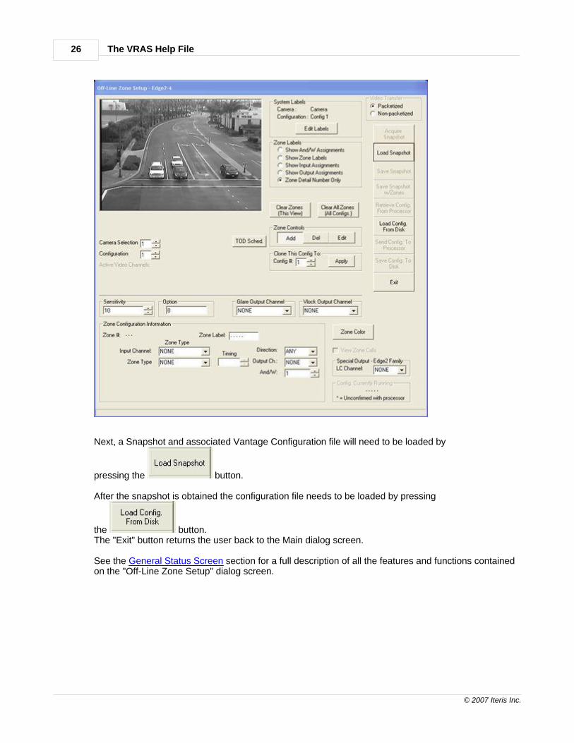
Next, a Snapshot and associated Vantage Configuration file will need to be loaded by
pressing the button.
After the snapshot is obtained the configuration file needs to be loaded by pressing
the button.The "Exit" button returns the user back to the Main dialog screen.
See the General Status Screen section for a full description of all the features and functions containedon the "Off-Line Zone Setup" dialog screen.
VRAS Walk Through 27
© 2007 Iteris Inc.
6.1.5 Exit
The Exit Button.
The "Exit" button closes the VRAS application.
The VRAS Help File28
© 2007 Iteris Inc.
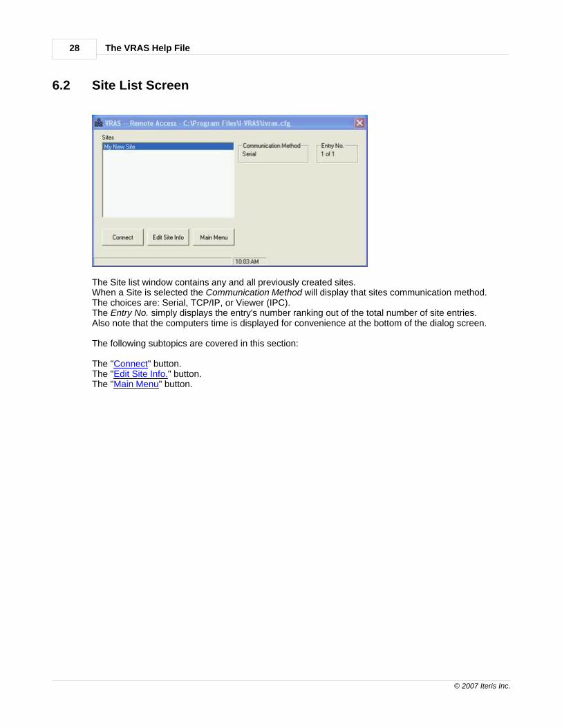
6.2 Site List Screen
The Site list window contains any and all previously created sites.When a Site is selected the Communication Method will display that sites communication method.The choices are: Serial, TCP/IP, or Viewer (IPC).The Entry No. simply displays the entry's number ranking out of the total number of site entries.Also note that the computers time is displayed for convenience at the bottom of the dialog screen.
The following subtopics are covered in this section:
The "Connect" button.The "Edit Site Info." button.The "Main Menu" button.

VRAS Walk Through 29
© 2007 Iteris Inc.
6.2.1 Connect
The "Connect" button brings up the General Status dialog screen.Go to the General Status Screen section for a full description of all the featuresand functions available there.
If an error message appears while you are attempting to connect, make sure that you are usingthe proper setup for the type of connection that you are trying to establish. See the Troubleshootingsection for further help with connection problems.
The VRAS Help File30
© 2007 Iteris Inc.
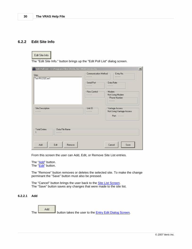
6.2.2 Edit Site Info
The "Edit Site Info." button brings up the "Edit Poll List" dialog screen.
From this screen the user can Add, Edit, or Remove Site List entries.
The "Add" button.The "Edit" button.
The "Remove" button removes or deletes the selected site. To make the changeperminant the "Save" button must also be pressed.
The "Cancel" button brings the user back to the Site List Screen.The "Save" button saves any changes that were made to the site list.
6.2.2.1 Add
The button takes the user to the Entry Edit Dialog Screen.

VRAS Walk Through 31
© 2007 Iteris Inc.
6.2.2.2 Edit
The button takes the user to the Entry Edit Dialog Screen.
6.2.2.3 Remove
The button removes or deletes the selected site. To make the changepermanent the "Save" button must also be pressed.
6.2.2.4 Cancel
The button brings the user back to the Site List Screen .
6.2.2.5 Save
The button saves any changes that were made to the site list.
6.2.3 Main Menu
The "Main Menu" button takes the user back to the VRAS Main Screen.

The VRAS Help File32
© 2007 Iteris Inc.
6.3 General Status Screen
The General Status Screen provides the status information that is shown above. Most of theinformation is self explanatory, however, a few of the statistics might require further explanation.
LC Status - This statistic is telling us which camera(s), if any, are currently in LC Mode.The "System LC channel" indicates whether a channel has been assigned to LC Out(the Low Contrast Output channel). This is especially significant in multiple cameraprocessors like the Vantage Plus. "LC Mode" causes all used channels, on the associatedcamera, to place constant calls. "System LC" causes all used channels on all cameras toplace constant calls. For more information on LC Mode refer to your Vantage productInstallation and Users Guide.
Processor Status - Gives the status of the processor."CPU OK" is normal. "CPU Fail" means the processor has failed and needs to be sent infor service. "SYNC" means that there is sync and video getting to the processor. "NO SYNC"means that there is no video getting to the processor from the video source."TRANSFER" means that there is internal video transfer. "NO TRANSFER" means that thereis not video transfer internal to the video unit. Normally, if there is video SYNC, there shouldalso be video TRANSFER.SYNC without TRANSFER is usually a sign of a unit failure and will require the unit to be sentin for service.NO SYNC and NO TRANSFER is normal when no video is being applied to the Vantage unit.

VRAS Walk Through 33
© 2007 Iteris Inc.
Glare Status - Gives the "Glare Status" (whether it is in Glare mode or Clear) for each of thecameras. The Glare Channel indicates whether a Glare Output Channel has been assignedto a specific camera.
Video Lock Output Assignment - Indicates per camera, whether an output channel has beenassigned to the Vlock feature. If an output channel is assigned to a camera, an external callwill be placed on the assigned output channel when that camera looses video sync.
Options - Shows the processor options that are currently set. See the firmware release notesfor specific information on processor options.
Video Format - Can be NTSC or PAL depending on what format was ordered at the time ofequipment purchase.
Sensitivity Settings - Shows the current camera sensitivity settings (1-10). See the firmwarerelease notes for specific information on camera sensitivity settings.
Unit ID - The units current four digit address ("0000" is default from the factory).
Hardware Configuration - Type of Vantage unit.
Processor Firmware Version - Vantage firmware version.
The button manually refreshes the General Status Screen data.While connected, the General Status Screen automatically refreshes every 15 seconds.
The following subtopics are covered in this section:
The "Detection Status" button.The "Video" button.The "Zone Setup" button.The "Retrieve MOE Data" button.The "Utilities" button.
The button takes you back to the Remote Access Site List screen.

The VRAS Help File34
© 2007 Iteris Inc.
6.3.1 Detection Status Screens
There are three different detection status screens in VRAS:
· Detection Status - shows status of Edge2 processors and Extension modules.
· TS2-IM Status - shows status of the TS2-IM module.
· IOM-32 Status - shows status of the IOM-32 module.
The detection status screen that you see will be dependent upon the Vantagehardware modules that are actually connected.
6.3.1.1 Detection Status
This screen shows the detection status information of Vantage Edge2 processors andExtension modules.
Update Interval - determines how often the detection status is updated (100ms - 2 sec.).Camera Input - determines the camera status data that will be displayed.
The "Start" button starts a real time status of unit detection.The "Stop" button stops the data display.The "Exit" button brings the user back to the General Status Screen.

VRAS Walk Through 35
© 2007 Iteris Inc.
6.3.1.2 TS2-IM Status
This screen shows the detection status information of a TS2-IM module.
Update Interval - determines how often the detection status is updated (100ms - 2 sec.).Camera Input - determines the camera status data that will be displayed.
The Red Ball indicates a Call (Output) or as an input it indicates phase state.The Yellow Ball indicates Learn Mode (Output) or as an input it indicates phase state.The Green Ball indicates Status Ok (Output) or as an input it indicates phase state. The VRAS can also detect if the controller is in Diagnostic Flash and will display theDiagnostic Flash indicator shown above.
The "Start" button starts a real time status of unit detection.The "Stop" button stops the data display.The "Exit" button brings the user back to the General Status Screen.

The VRAS Help File36
© 2007 Iteris Inc.
6.3.1.3 IOM-32 Status
This screen shows the detection status information of a IOM-32 module.
Update Interval - determines how often the detection status is updated (100ms - 2 sec.).Camera Input - determines the camera status data that will be displayed.
The "Start" button starts a real time status of unit detection.The "Stop" button stops the data display.The "Exit" button brings the user back to the General Status Screen.

VRAS Walk Through 37
© 2007 Iteris Inc.
6.3.2 Video
The Video button brings up the Video dialog screen shown above.From here the user can Acquire Snapshots, Load previously saved Snapshots, orretrieve Continuous Snapshots.
The following subtopics are covered in this section:
The "Acquire Snapshot" button.The "Load Snapshot" button.The "Save Snapshot" button.The "Start Continuous Mode" button.The "Update Video Channel Status" button.The "Save Snapshots to File" checkbox
The Video Transfer box allows the user to select either Packetized or Non-packetizedvideo transfers. Try the Non-packetized option first, it is faster and usually works for mostapplications. As the name implies the data is not packetized and there is no errorchecking. If the Non-packetized option does not work, or if you want the error checkingenabled, choose the Packetized option.
The Camera Selection box selects which camera source to retrieve the snapshot from onmultiple camera Vantage units.
The Active Video Channel status tells the user which channels currently have active video.The status can be manually updated by pressing the "Update Channel Status" button.
The "Exit" button takes the user back to the General Status Dialog Screen.
The VRAS Help File38
© 2007 Iteris Inc.
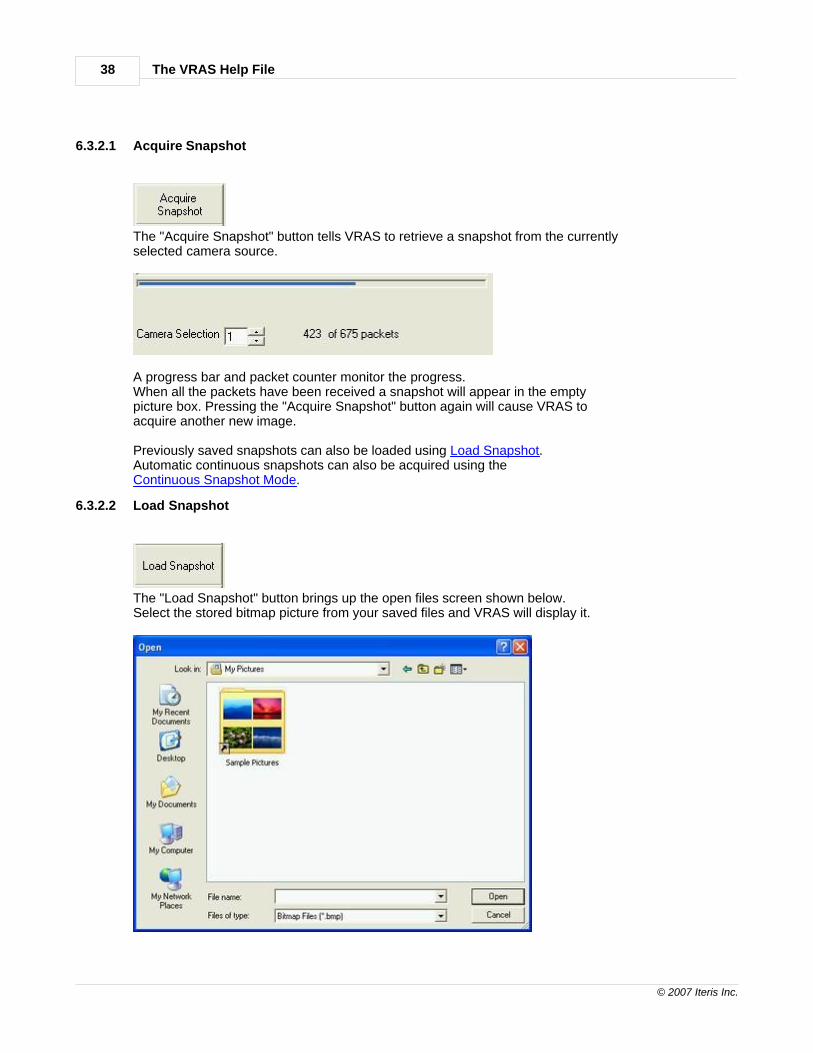
6.3.2.1 Acquire Snapshot
The "Acquire Snapshot" button tells VRAS to retrieve a snapshot from the currentlyselected camera source.
A progress bar and packet counter monitor the progress.When all the packets have been received a snapshot will appear in the emptypicture box. Pressing the "Acquire Snapshot" button again will cause VRAS toacquire another new image.
Previously saved snapshots can also be loaded using Load Snapshot.Automatic continuous snapshots can also be acquired using theContinuous Snapshot Mode.
6.3.2.2 Load Snapshot
The "Load Snapshot" button brings up the open files screen shown below.Select the stored bitmap picture from your saved files and VRAS will display it.

VRAS Walk Through 39
© 2007 Iteris Inc.
6.3.2.3 Save Snapshot
The "Save Snapshot" button allows the user to save a snapshot to file.Press the "Save Snapshot" button and the save file dialog will come up.Select a directory and file name to save your snapshot to. Press "Save"and the snapshot will be saved to your hard drive in the selected directory.
6.3.2.4 Start Continuous Mode
The "Start Continuous Mode" button will cause VRAS to continuously retrieve snapshotsfrom the selected camera source until the "Stop Continuous Mode" button is pressed.
6.3.2.5 Update Channel Status
The "Update Video Channel Status" button causes VRAS to manually update the statusof the Active Video Channels.
6.3.2.6 Save Snapshots to File
When the "Save Snapshots to File" checkbox is checked, snapshots will automaticallybe saved to file. They will be saved to the VRAS installation (\\Program Files\Iteris, Inc\VRAS)folder on the users computer approximately once every forty seconds (Default) or to the userselected folder. The files name will look like the following example: 8-11-2006 8-30-44.bmpIn this example 8-11-2006 (MM-DD-YYYY) is the date and 8-30-44 is the time (hh-mm-ss).MM = Month, DD = Day, and YYYY = Year. hh = Hours, mm = Minutes, and ss = Seconds.Snapshots are saved in the BMP graphics format.

The VRAS Help File40
© 2007 Iteris Inc.
6.3.3 Zone Setup Screen
Camera Selection - currently selected camera video source.
Configuration - select the loaded Vantage configuration.
Active Video Channels - current video channels that actually have video.
TS2-IM Listen Only Mode - (TS2-IM module only) the status of the listen only DIPswitches will be displayed here. (Which ports are enabled or disabled)
TS2-IM BIU Address - (TS2-IM module only) the status of the BIU address DIPswitches will be displayed here. (Which BIU addresses are enabled 8,9,10,11)
Special Output - this is where the user can select a LC (Low Contrast) Output channel. TheLC Output channel will then place a constant call whenever the system is in LC Mode. Seethe Vantage Installation and User Guide for more information on the LC Output Channel.
Config. Currently Running - this is the currently running configuration.
VRAS Walk Through 41
© 2007 Iteris Inc.
View Zone Calls - this check box, when checked, allows the user to enable the use of anactive overlay to show real time zone activations. There must be an active connectionestablished and an active configuration loaded before this feature can be properly activated.
See the following subtopics in this section for more information on these items:
System LabelsZone LabelsZone ControlsZone Configuration InformationSensitivityOptionGlare Output ChannelVlock Output Channel
The "Clear Zones" button clears all the zones from the current camera view.
The "Clear All Zones" button clears all the zones on all camera views.Each of the three saved configurations is cleared.Be careful using these functions, there is no "undo" or recover function.
The following subtopics are covered in this section:
The "Acquire Snapshot" button.The "Load Snapshot" button.The "Save Snapshot" button.The "Save Snapshot with Zones" button.The "Retrieve Configuration From Processor" button.The "Load Configuration from Disk" button.The "Send Configuration to Processor" button.The "Save Configuration to Disk" button.The "Clone Config. to" "Apply" button.The "TOD Sched." buttonThe "Zone Color" button.The "Special LC Output" feature.The "View Zone Calls" check box.
The "Exit" button takes the user back to the General Status Dialog Screen.

The VRAS Help File42
© 2007 Iteris Inc.
6.3.3.1 Acquire Snapshot
See description under Video section.Here is a link "Acquire Snapshot".
6.3.3.2 Load Snapshot
See description under Video section.Here is a link "Load Snapshot".
6.3.3.3 Video Transfer
Packetized - this selection sends the video snapshot transfer information in packets. Sendinginformation is packets is the most reliable way to send video snapshot data,however, it can be to slow and is unnecessary for some applications. Packetsof data that do not arrive after being sent will be resent up to three times beforetiming out.
Non-packetized - this selection sends the video snapshot transfer information without usingpackets. This selection is much faster, but should only be used with a reliabletransmission source. Examples of reliable transmission sources are: Ethernetand direct connection. Another application that requires this selection is theVantage Viewer when using it with VRAS. Missing or corrupted data will causeonly partial snapshot retrieval and can also cause data retrieval timeouts.
In general, you can try the non-packetized option first; if errors occur, then try the packetizedoption.

VRAS Walk Through 43
© 2007 Iteris Inc.
6.3.3.4 System Labels
The "Edit Labels" button brings up the Edit Labels dialog screen shown below.
From this screen the user can easily rename or edit either the camera labels or the configurationlabels.Press the "Save" button to save your changes or press the "Exit" button to cancel any changes andreturn to the Zone Setup dialog screen.
6.3.3.5 Zone Labels
The Zone Label controls allow the user to select how they would like to see the zonereferences appear on screen.
Show And/W Assignments - reference zones by their associated parent zone.Show Zone Labels - reference zones by their zone label.Show Input Assignments - reference zones by their input channel assignments.Show Output Assignments - reference zones by their output channel number.Zone Detail Number Only - reference zones by their detail number.

The VRAS Help File44
© 2007 Iteris Inc.
6.3.3.6 Zone Controls
The Zone Controls allow the user to Add, Delete, or Edit individual zones.First select Add, Delete, or Edit. Then click on the zone that you want to alter.
The "Add" button allows the user to Add additional new zones. (Drawing new zones) Afterpressing the Add button, place the pointer where you want the back left corner of your zoneto be. Click the left mouse button to anchor the first corner. Next, move the mouse pointerto where you want your new zones right rear corner to be. Left click the mouse to anchor thesecond corner. Now move the mouse pointer to the position that you want your new zonesright front corner to occupy. Left click the mouse to anchor the third corner. Lastly, move themouse pointer to the desired location of the left front zone corner. Left click the mouse toanchor this final corner, your zone is completed. The corners are placed in a clockwise fashion,rear corners and then the front corners. If you make a mistake zones can easily be modified byusing the Move function (Move is one of the Edit functions) or they can be deleted and redrawnusing the Delete button described in detail below.
The "Del" or Delete button does exactly what it says; it deletes zones. First, press the "Del"button, then select the zone you want to delete and left click it with your mouse pointer. Theselected zone will be deleted. Remember that the configuration must be sent to the processoror saved in order to preserve any changes that you may make to the loaded configuration.

VRAS Walk Through 45
© 2007 Iteris Inc.
A new warning message has been added to the delete zone function.
The "Edit" button allows the user to access a large collection of editing functions.
Editing Zone Parameters With the "Edit" button depressed, select a zone by left clicking insideit with the mouse pointer; the information for that zone will be displayed in the Zone ConfigurationInformation box as it is shown below.
These zone parameters can also be changed from this same box. Simply select the desiredvalues from the various drop down menus or value incrementing buttons.
Moving A ZoneMake sure the "Edit" button is depressed and select a zone with the mouse pointer whileholding down the left mouse button. With the left mouse button still depressed move the mousepointer and the whole zone will move along with it. When you have the zone where you want it,release the left mouse button and the zone will stay where you have placed it.
Changing Zone Size and ShapeWith the "Edit" button depressed, select a zone and double left click on one of its corners whileholding down the left mouse button on the second click. You will now be able to move the cornerthat you selected along with its opposing corner. With the left mouse button still depressed movethe zone corners to the desired location. When you are satisfied with their position release theleft mouse button and the corners will be locked in place. Repeat this same process with theappropriate zone corners until you have the desired size and shape of your zone.
Remember: you must send the configuration to the processor or save it in order to preserve anychanges that you have made.
The VRAS Help File46
© 2007 Iteris Inc.
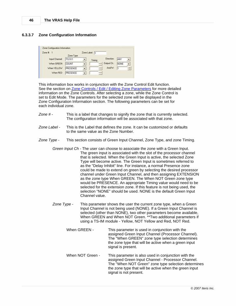
6.3.3.7 Zone Configuration Information
This information box works in conjunction with the Zone Control Edit function.See the section on Zone Controls / Edit / Editing Zone Parameters for more detailedinformation on the Zone Controls. After selecting a zone, while the Zone Control isset to Edit Mode. The parameters for the selected zone will be displayed in theZone Configuration Information section. The following parameters can be set foreach individual zone.
Zone # - This is a label that changes to signify the zone that is currently selected.The configuration information will be associated with that zone.
Zone Label - This is the Label that defines the zone. It can be customized or defaultsto the same value as the Zone Number.
Zone Type - This section consists of Green Input Channel, Zone Type, and zone Timing.
Green Input Ch - The user can choose to associate the zone with a Green Input.The green input is associated with the slot of the processor channelthat is selected. When the Green Input is active, the selected ZoneType will become active. The Green Input is sometimes referred toas the "Delay Inhibit" line. For instance, a normal Presence zonecould be made to extend on green by selecting the desired processorchannel under Green Input Channel, and then assigning EXTENSIONas the zone type When GREEN. The When NOT Green zone typewould be PRESENCE. An appropriate Timing value would need to beselected for the extension zone. If this feature is not being used, theselection "NONE" should be used. NONE is the default Green InputChannel value.
Zone Type - This parameter shows the user the current zone type, when a GreenInput Channel is not being used (NONE). If a Green Input Channel isselected (other than NONE), two other parameters become available,When GREEN and When NOT Green. **Two additional parameters ifusing a TS-IM module - Yellow, NOT Yellow and Red, NOT Red.
When GREEN - This parameter is used in conjunction with theassigned Green Input Channel (Processor Channel). The "When GREEN" zone type selection determinesthe zone type that will be active when a green inputsignal is present.
When NOT Green - This parameter is also used in conjunction with theassigned Green Input Channel - Processor Channel.The "When NOT Green" zone type selection determinesthe zone type that will be active when the green inputsignal is not present.

VRAS Walk Through 47
© 2007 Iteris Inc.
**When GREEN - This parameter is used in conjunction with theassigned Input Channel (Processor Channel). The "When GREEN" zone type selection determinesthe zone type that will be active when a green inputsignal is present.
**When Yellow This parameter is used in conjunction with theassigned Input Channel (Processor Channel). The "When Yellow" zone type selection determinesthe zone type that will be active when a green inputsignal is present.
**When Red This parameter is used in conjunction with theassigned Input Channel (Processor Channel). The "When Red" zone type selection determinesthe zone type that will be active when a green inputsignal is present.
Note: "**" Denotes Available with the TS2-IM module Only.
Timing - This parameter allows the user to select the timing for Delay,Extension, and Pulse type zones.
Direction - This parameter determines the directionality of the zone. The choices are Anyor Down. "Any" detects from any direction. "Down" primarily detects vehicles traveling in the downward direction.
Output Ch - The Output Channel is the Vantage processor channel that is associated withthe detection zone. When the zone is active, a call will be placed on theassigned Output Channel.
And/W - This parameter shows the current zone And/W status and allows the user tochange the And/W zone association. The default value is the same as the current zones Zone Number. If a different Zone Number value is assigned tothe And/W parameter, that other zone will be "Anded" with the current zone.Now, both zones will need to be active before a call can be placed on theparent zones Output Channel. Be careful that you understand this functionbefore you change And/W from its default value.
The Zone Configuration Information section not only displays the currently selected zone'sparameters, but also allows the user to easily edit them.

The VRAS Help File48
© 2007 Iteris Inc.
6.3.3.8 Save Snapshot
You must Load or Acquire a snapshot before you can Save it.
Press the "Save Snapshot" button and you will be prompted to choose where you want tosave the bitmap and you will need to choose a descriptive name for it.
6.3.3.9 Save Snapshot With Zones
In order to save a snapshot with zones you must have previously loaded a snapshotand a configuration.
The "Save Snapshot W/Zones" button saves a bitmap image with the snapshot and the overlay.
6.3.3.10 Retrieve Configuration From Processor
The "Retrieve Config. From Processor" button uploads the processor configuration into theVRAS program so it can be evaluated or edited.
6.3.3.11 Load Configuration From Disk
The "Load Config. From Disk" button loads a previously saved configuration from yourcomputer hard drive into VRAS so it can be evaluated or edited.
6.3.3.12 Send Configuration to Processor
The "Send Config. To Processor" button allows the user to send the currently loadedconfiguration from VRAS back to the Vantage unit. In this way configurations andsnapshots can be loaded from the Vantage unit to VRAS, modified in VRAS, and thensent back to the Vantage unit again.

VRAS Walk Through 49
© 2007 Iteris Inc.
6.3.3.13 Save Configuration to Disk
The "Save Config. To Disk" button allows the user to save configurations to their computerhard drive. With this feature the user can archive and backup various Vantage locationconfigurations for future reference.
6.3.3.14 Clone Configuration
The Clone Config To function allows the user to quickly clone (copy) the currentlyloaded (displayed) configuration to the selected alternate configuration [Config#:1, 2, or 3].Select the desired configuration to clone (copy), then press the "Apply" buttonto copy and save the current configuration to the selected alternate configuration.

The VRAS Help File50
© 2007 Iteris Inc.
6.3.3.15 TOD Schedule
This button will fill up the "Weekly Timing Table" with configuration 1.
This button will fill up the "Weekly Timing Table" with configuration 2.
This button will fill up the "Weekly Timing Table" with configuration 3.
This button will cancel any changes that were made and bring you back tothe “Zone Setup” screen.
This button saves the changes that were made to the “Weekly Timing Table”and sends the table information to the processor.
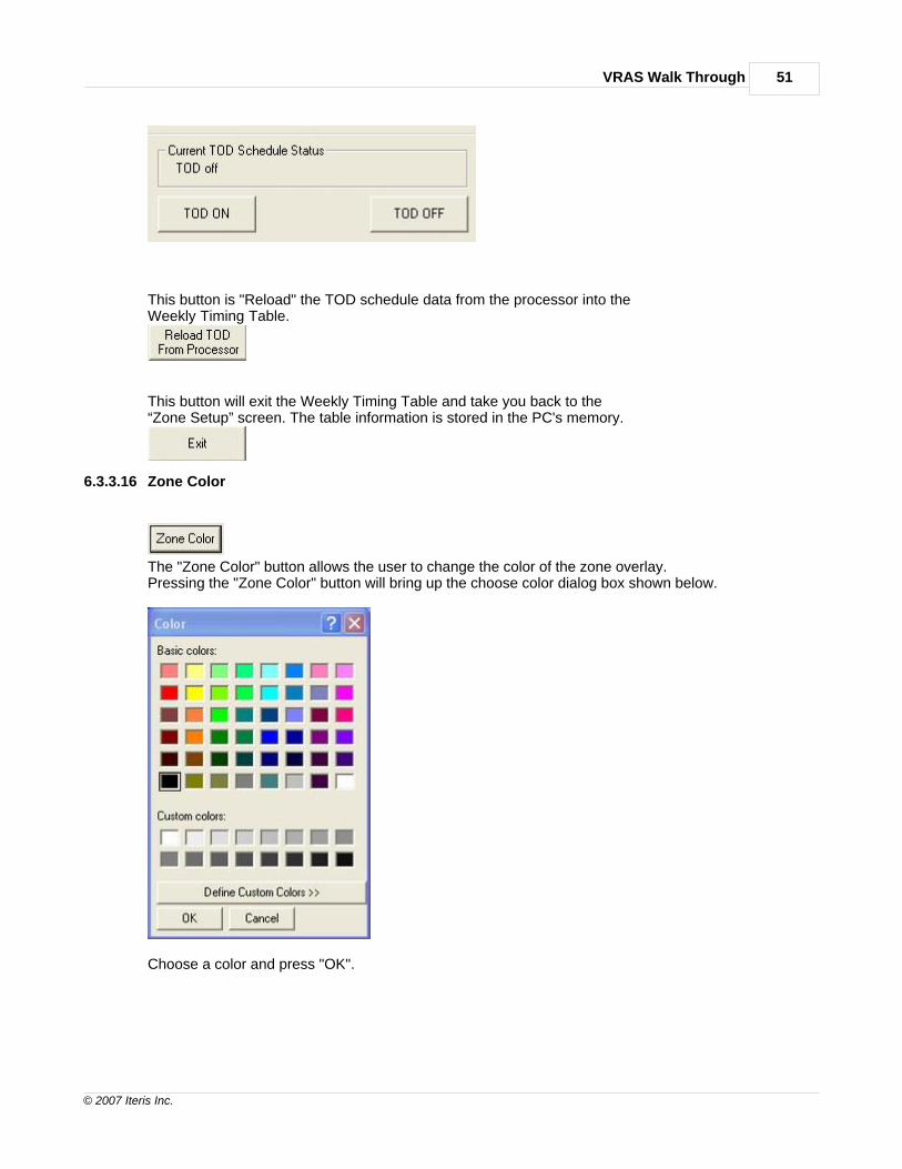
The TOD ON button enables the Weekly Timing Table on the processor.
The TOD OFF button disables the Weekly Timing Table on the processor.Note: The “Apply Now" button does not need to be pressed.
VRAS Walk Through 51
© 2007 Iteris Inc.
This button is "Reload" the TOD schedule data from the processor into theWeekly Timing Table.
This button will exit the Weekly Timing Table and take you back to the“Zone Setup” screen. The table information is stored in the PC's memory.
6.3.3.16 Zone Color
The "Zone Color" button allows the user to change the color of the zone overlay.Pressing the "Zone Color" button will bring up the choose color dialog box shown below.
Choose a color and press "OK".

The VRAS Help File52
© 2007 Iteris Inc.
6.3.3.17 Special LC Output
This item allows the user to select an unused channel to assign as an output whenthe Vantage unit goes into System LC mode.Please refer to the Vantage User and Installation guide for more information onthe System LC Channel feature.
6.3.3.18 View Zone Calls
When the "View Zone Calls" check box is selected, a real time zone detection statuscan be displayed on the retrieved snapshot.When the Detection Status screen comes up, choose "Start" and move the screenwindow out of the way. Switch back to the Zone Setup screen and now you canobserve the zones detection actuations.
6.3.3.19 Sensitivity
The Sensitivity combo box allows the user to select a camera sensitivity setting. The allowable settings are 1-10. Please consult the firmware release notes for the correctsettings for your camera hardware type.
6.3.3.20 Option
The Option box allows the user to select special algorithm option features on a percamera basis. Refer to the firmware version release notes for valid Option settinginformation.
6.3.3.21 Glare Output Channel
This combo box allows the user to select a Glare Output Channel on a per camerabasis. Remember, the Glare Output Channel should only be assigned to an unusedprocessor channel. You should never use a processor channel for both vehicle detectionand a special output assignment. A dedicated processor output channel is required forthis function.

VRAS Walk Through 53
© 2007 Iteris Inc.
6.3.3.22 Vlock Output Channel
This combo box allows the user to select a Vlock Output Channel on a per camerabasis. The Vlock Output Channel gives the user the ability to place a call on theassigned external output when camera sync is lost. Remember, the Vlock OutputChannel should only be assigned to an unused processor channel. You should neveruse a processor channel for both vehicle detection and a special output assignment.A dedicated processor output channel is required for this function.

The VRAS Help File54
© 2007 Iteris Inc.
6.3.4 Retrieve MOE Data
The Retrieve MOE Data screen is the screen where data can be retrieved from the Vantage unitand saved to a file using a series of specialized data collection functions.
Data Filename - is where you can select a file name for a data file to save the desired data afterit is has been retrieved and collected from the buffer of the Vantage processor unit.
The following subtopics are covered in this section:
The "Bin Reset" button.The "Bin All" button.The "Bin Last" button.The "Bin New" button.The "Bin Today" button.The "Bin Yesterday" button.The "Terminate Bin Data Dump" button.The "Set Bin Interval" button.The "Clear Display" button.
The "Exit" button exits the Retrieve MOE Data dialog screen and returns the user to theGeneral Status dialog screen.

VRAS Walk Through 55
© 2007 Iteris Inc.
The data string for counts used by the Vantage intersection software is defined as follows :
Up until firmware version 1.11ddd,YYYY-MM-DD hh:mm:ss,ccccc,video statusdetail number,year-month-day hour:minutes:seconds,vehicle count,video status
Firmware version 1.12 and above (CSO zone type added).ddd,YYYY-MM-DD hh:mm:ss,c,s,o,Cs,Cm,Cl,GT,STdetail number,year-month-day hour:minutes:seconds,count,speed,occupancy,count small,count medium,count large,green time,video status
ddd=Zone numberYYYY=YearMM=MonthDD=Dayhh=Hourmm=Minutess=Secondc=Counts=Speedo=OccupancyCs=Counts small vehicleCm=Counts med vehicleCl=Counts large vehicleGT =Green TimeST=Video Status
6.3.4.1 Bin Reset
The "Bin Reset" button erases (deletes) all the data in the Vantage unit bin or buffer.Use this command with caution; once the data is deleted using "Bin Reset" it cannot berecovered.
6.3.4.2 Bin All
The "Bin All" button retrieves ALL the data in the Vantage units bin (buffer).Note: This file can be quite large and can take a few minutes to retrieve.

The VRAS Help File56
© 2007 Iteris Inc.
6.3.4.3 Bin Last
The "Bin Last" button retrieves the last complete data sample.The bin sample size is determined by the interval setting.See Set Bin Interval for more information.
6.3.4.4 Bin New
The "Bin New" button retrieves the newest bin information since the last"Bin New" command.
6.3.4.5 Bin Today
The "Bin Today" button retrieves all of today's bin data.
Important Note: The Vantage processor must be running overnight to have a reference pointfor using "Bin Today" or "Bin Yesterday" since the reference point time stamp occurs at midnight.
6.3.4.6 Bin Yesterday
The "Bin Yesterday" button retrieves all of yesterdays data.
Important Note: The Vantage processor must be running overnight to have a reference pointfor using "Bin Today" or "Bin Yesterday" since the reference point time stamp occurs at midnight.
6.3.4.7 Terminate Bin Data Dump
The "Terminate Bin Data Dump" button, when pressed, will immediately terminate a bin datadump. This feature allows the user to abort the bin data dump immediately without havingto wait for it to complete, which can take several minutes depending upon the amount ofdata already accumulated in the bin.

VRAS Walk Through 57
© 2007 Iteris Inc.
6.3.4.8 Set Bin Interval
The "Set Bin Interval" button brings up the Bin Interval dialog screen as shown below.
Enter in the desired bin data collection interval from the drop down menu.Your choices are:Press the "Apply" button to validate your choice or press the "Cancel" button to abortany changes.Press the "Exit" button to return to the Retrieve MOE Data dialog screen.
6.3.4.9 Clear Display
The "Clear Display" button clears the data display screen.

The VRAS Help File58
© 2007 Iteris Inc.
6.3.4.10 Saving Data
Use your default filename or create a new Data Filename and enter it in the text box.You can also use a previously saved data file by selecting the "Browse" button.
Default Filename from Entry Editor Screen
Make sure the "Log To File" check box is checked if you want to write data to the specified file.If the file is new and does not already exist a new file will be created with the name specified.If a location is not specified then the default location for the file will be used. The default locationis the VRAS installation directory whose path is normally:C:\Program Files\Iteris, Inc\VRAS\Test.txt.
When the "Log To File" and or "Append To File" boxes are checked, and a filename is specified,pushing any of the data retrieval buttons will result in data being written to the specified file.
If you are writing data to an existing file, and only the "Log To File" box is checked(Not the "Append To File box), realize that any previous data in the specified file will be overwrittenwith the newly retrieved data.
If you want to add data (Append Data) to a file without overwriting the previous data in the file, thenyou need to make sure that the "Append To File" box is also checked so the existing file data willnot be overwritten.
Important Note: The data time stamp is based on the currently set Vantage processor time. If theVantage processor time is not set correctly, then the data time stamps will also be incorrect.You can set the Vantage processor time from the clock menu (CLK) item on the Vantage unitdirectly or you can do it remotely using VRAS from the Utilities - Set Time or the Sync To PCClock function. Use one of these methods to set the Vantage unit time correctly.

VRAS Walk Through 59
© 2007 Iteris Inc.
6.3.5 Utilities Screen
The Utilities dialog screen has buttons to access a wide range of utility functions.
The following subtopics are covered in this section:
The "Reset Processor" button.The "Assign Unit ID" button.The "Reset EM" (Reset Extension Module) button.The "Set Time" button.The "Sync To PC Clock" button.The "Reset Zone" button.The "Set Inactive Channel" button.The "Set Max Recall" button.The "Timestamp Overlay Display" button.The "Display Counts Overlay" button.The "Video Output On/Off" button.The "Output Overlay On/Off" button.The "Switch Video Output" button.The "Set Display Mode" button.The "TOD Schedule On/Off" button.The "Change Percent LC Threshold" button.The "Run New Config" button.
The "Exit" button exits the Utilities dialog screen and returns the user back to theGeneral Status dialog screen.

The VRAS Help File60
© 2007 Iteris Inc.
6.3.5.1 Reset Processor
The "Reset Processor" button resets the Vantage processor.
Realize that when you reset the Vantage processor you willhave to reconnect again since communication will be lostduring the processor reboot.
6.3.5.2 Assign Unit ID
The "Assign Unit ID" button allows the user to change the Vantage units address (Unit ID).Normally, this address is left with the value of "0000" (Factory Default).
The only time this address is normally required to be changed is for Multi-drop operation,where each Vantage unit in the chain must have a unique Unit ID or communication betweenmultiple units will not be possible. For more information on Multi-drop refer to the Multi-dropsection of this help file.
The existing Unit ID will be displayed.Enter the new desired Unit ID in the text box. "0000" is the factory default.Press the "Apply" button to send the new Unit ID to the Vantage unit.The new changed Unit ID will now be displayed.
Note: Changing the Unit ID here will also change the Site Address Book Unit ID entry.
VRAS Walk Through 61
© 2007 Iteris Inc.
Press the "Exit" button to return to the Utilities Dialog Screen.
Make sure that you write down the new Unit ID, because if you forget it,you will not be able to access the Vantage unit again without it.
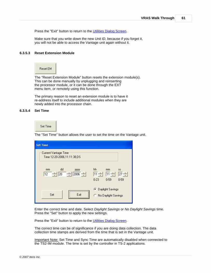
6.3.5.3 Reset Extension Module
The "Reset Extension Module" button resets the extension module(s).This can be done manually by unplugging and reinsertingthe processor module, or it can be done through the EXTmenu item, or remotely using this function.
The primary reason to reset an extension module is to have itre-address itself to include additional modules when they arenewly added into the processor chain.
6.3.5.4 Set Time
The "Set Time" button allows the user to set the time on the Vantage unit.
Enter the correct time and date. Select Daylight Savings or No Daylight Savings time.Press the "Set" button to apply the new settings.
Press the "Exit" button to return to the Utilities Dialog Screen.
The correct time can be of significance if you are doing data collection. The datacollection time stamps are derived from the time that is set in the Vantage unit.
Important Note: Set Time and Sync Time are automatically disabled when connected tothe TS2-IM module. The time is set by the controller in TS-2 applications.

The VRAS Help File62
© 2007 Iteris Inc.
6.3.5.5 Sync to PC Clock
The "Sync. To PC Clock" button allows the user to synchronize the Vantage unit timewith the current computer time.
The Current Vantage Processor Time displays the current Vantage unit time.The Current PC Time is the current computer time.
The "Set" button will synchronize the Vantage unit time with the current computer time.The "Exit" button will return the user to the Utilities Dialog Screen.
Important Note: Set Time and Sync Time are automatically disabled when connected tothe TS2-IM module. The time is set by the controller in TS-2 applications.
6.3.5.6 Reset Zone
The "Reset Zone" button allows the user to reset an individual zone
Select the desired zones camera number.Select the desired zone number.
Press the "Apply" button to reset the selected zone and to cause it to re-learn.

VRAS Walk Through 63
© 2007 Iteris Inc.
The channel assigned to the zone will recall during the re-learn period.
Press the "Exit" button to return to the Utilities Dialog Screen.
6.3.5.7 Set Inactive Channel
The "Set Inactive Channel" button allows the user to set all Inactive Channels(Unused Channels) to place constant calls.The default is for Inactive Channels not to place constant calls.
Press the "Set To Call" button to have Inactive Channels place constant calls.Press the "Set To No Call" button to have Inactive Channels not place constant calls.
Press the "Exit" button to return to the Utilities Dialog Screen.
6.3.5.8 Set Max Recall
The "Set Max Recall" button allows the user to place all channels onMax Recall (Constant Call).
Press the "Set Max Recall" button to place all channels on Max Recall.Press the "Clear Max Recall" button to take all channels off of Max Recall.
Press the "Exit" button to return to the Utilities Dialog Screen.

The VRAS Help File64
© 2007 Iteris Inc.
6.3.5.9 Timestamp Overlay Display
The "Timestamp Overlay Display" button brings up the Display Timestamp dialog box shown below.
The "Display ON" button turns on the time display on the Vantage processor.The time display shows up right above the camera label.
The "Display OFF" button turns off the time display on the Vantage processor.
The "Exit" button exits the Display Timestamp function.
6.3.5.10 Display Counts Overlay
The "Display Counts On Overlay" button turns On the counts screen overlay.
Press the "Count Display On" button to turn On the count screen overlay.Press the "Count Display Off" button to turn Off the count screen overlay.Press the "Exit" button to return to the Utilities screen.

VRAS Walk Through 65
© 2007 Iteris Inc.
6.3.5.11 Video Output On/Off
The "Video Output On/Off" button is used to turn output video ON or OFF remotely.
Press the appropriate button to remotely place the output video in the desired state.
The "Exit" button will take the user back to the Utilities Dialog Screen.
6.3.5.12 Output Overlay On/Off
The "Output Overlay On/Off" button turns the overlay ON or OFF.The overlay is the collection of graphics that include the zone actuations, label designators,and the camera label.
Press the "Overlay OFF" button to disable the overlay.Press the "Overlay ON button to re-enable the overlay (Default is ON).
Press the "Exit" button to return to the Utilities Dialog Screen.
6.3.5.13 Switch Video Output (Access)
This section is relevant only if you are using VRAS to connect to a Vantage Access Module.
The VRAS Help File66
© 2007 Iteris Inc.
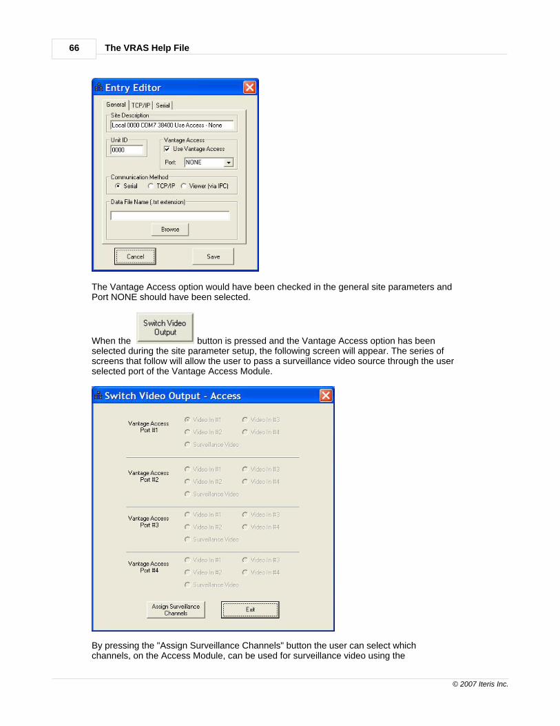
The Vantage Access option would have been checked in the general site parameters andPort NONE should have been selected.
When the button is pressed and the Vantage Access option has beenselected during the site parameter setup, the following screen will appear. The series ofscreens that follow will allow the user to pass a surveillance video source through the userselected port of the Vantage Access Module.
By pressing the "Assign Surveillance Channels" button the user can select whichchannels, on the Access Module, can be used for surveillance video using the
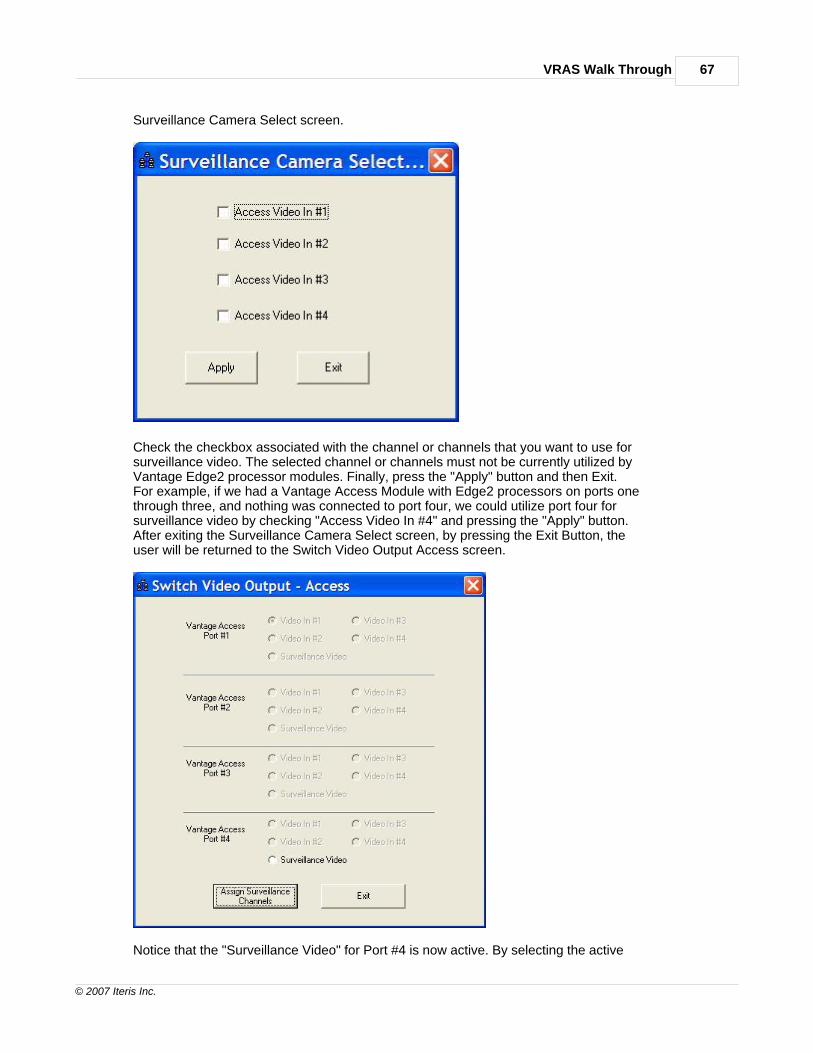
VRAS Walk Through 67
© 2007 Iteris Inc.
Surveillance Camera Select screen.
Check the checkbox associated with the channel or channels that you want to use forsurveillance video. The selected channel or channels must not be currently utilized byVantage Edge2 processor modules. Finally, press the "Apply" button and then Exit.For example, if we had a Vantage Access Module with Edge2 processors on ports onethrough three, and nothing was connected to port four, we could utilize port four forsurveillance video by checking "Access Video In #4" and pressing the "Apply" button.After exiting the Surveillance Camera Select screen, by pressing the Exit Button, theuser will be returned to the Switch Video Output Access screen.
Notice that the "Surveillance Video" for Port #4 is now active. By selecting the active

The VRAS Help File68
© 2007 Iteris Inc.
Surveillance Video option the user can now switch to the surveillance video sourceconnected to Port #4 on the Access Module.
In summary, the user connected directly to the Access Module, assigned an unusedAccess Module port to a surveillance video source (Port #4 in our example), and thenwas able to switch to that video source using the Vantage Access Module "SwitchVideo Output" screen.
6.3.5.14 Switch Video Output
The "Switch Video Output" button allows the user to switch video output remotely onmultiple video input Vantage systems. A different video input can be remotely selectedto be output by the Vantage processor.
The Current Video Output shows which video output is currently selected.The Active Video Channels shows which video channels are available with active video.
Select the video camera source. Press the "Apply" button to switch to the new videosource. The new source will now show up as the Current Video Output.
Press the "Exit" button to return to the Utilities Dialog Screen.
6.3.5.15 Set Display Mode
The "Set Display "Mode" button allows the user to change the zone reference criteria.The zone reference choices are shown below :

VRAS Walk Through 69
© 2007 Iteris Inc.
Select the desired zone reference choice from the drop down menu.Channel is the default value.Press the "Apply" button to implement your choice.
Press the "Exit" button to return to the Utilities Dialog Screen.
6.3.5.16 TOD Schedule On/Off
The "TOD Schedule On/Off" button turns On or Off the TOD schedule function forthe associated processor module.
Press the "TOD On" button to turn On the TOD function.

The VRAS Help File70
© 2007 Iteris Inc.
Press the "TOD Off" button to turn Off the TOD function.Press the "Exit" button to return to the Utilities screen.
6.3.5.17 LC Threshold
The "Change % LC Threshold" button allows the user to set the threshold required for thesystem to go into LC recall.
Your choices are: Edge2-2: 50 (Default), 100Edge2-4: 25, 50 (Default),75 ,100Make your choice and press the "Apply" button.Then press the "Exit" button to return to the Utilities screen.
Examples:If you choose 100 on an Edge2-2 processor module, it means that both cameras(100%) must be in LC mode before the system will go into LC mode.If you choose 50 on an Edge2-2 processor module, it means that only one of thetwo cameras (50%) must be in LC mode before the system will go into LC mode.If you choose 25 on an Edge2-4 processor module, it means that only one of thefour cameras must be in LC mode before the system will go into LC mode and placeconstant calls.
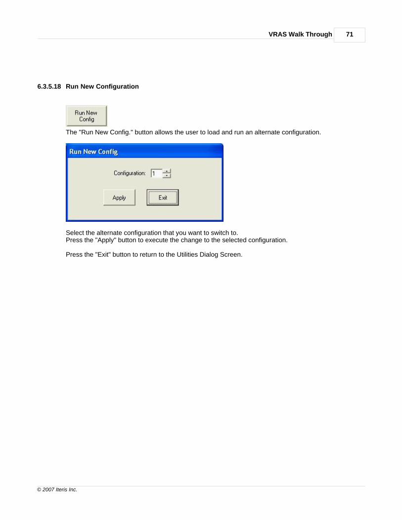
VRAS Walk Through 71
© 2007 Iteris Inc.
6.3.5.18 Run New Configuration
The "Run New Config." button allows the user to load and run an alternate configuration.
Select the alternate configuration that you want to switch to.Press the "Apply" button to execute the change to the selected configuration.
Press the "Exit" button to return to the Utilities Dialog Screen.
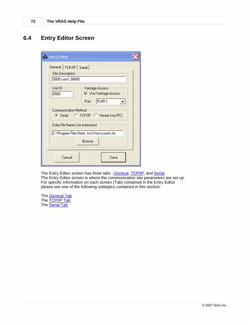
The VRAS Help File72
© 2007 Iteris Inc.
6.4 Entry Editor Screen
The Entry Editor screen has three tabs : General, TCP/IP, and Serial.The Entry Editor screen is where the communication site parameters are set up.For specific information on each screen (Tab) contained in the Entry Editorplease see one of the following subtopics contained in this section:
The General TabThe TCP/IP TabThe Serial Tab

VRAS Walk Through 73
© 2007 Iteris Inc.
6.4.1 Data File Name
A Data File Name can be created or selected in advance here to be stored as thedefault bin data collection file associated with the related site.
The "Browse" button can be used to select a previously saved file in a specific location.When a new file is created without using the " Browse" button it will created in thedefault directory path which is : C:\Program Files\Iteris, Inc\VRAS\ *****.txt.
For additional information on saving data files see the Saving Data section under theRetrieve MOE Data heading.
6.4.2 Save
The "Save" button is used when all the parameters have been setfor the site that is being created.Pressing "Save" will save all the settings that are associated with the newly createdsite.
6.4.3 Cancel
The "Cancel" button takes the user back to the Site List Dialog Screen.

The VRAS Help File74
© 2007 Iteris Inc.
6.4.4 General Tab
Site Description - the identifying name of the site that is to be created.Enter in a unique and meaningful site description in the text box.
Unit ID - the unique four digit address of the Vantage unit. The user can enter ina new four digit ID in the text box provided. It is recommended that the Unit ID beleft set to the factory default of "0000" unless multi-drop operation is required.Click on the Multi-drop link for more information on Multi-drop operation.
Vantage Access - this section is where you tell VRAS you will be connecting to a Vantage Access module. Check the "Use Vantage Access" checkbox and then select one of the fourRJ45 ports associated with the Edge2 processor that you want to connect to. If port "NONE"is selected and the "Use Vantage Access" checkbox is checked, you will connect to theAccess module and not to one of the attached Edge2 processor modules. The Switch VideoOutput surveillance channel assignment screen will be displayed. See the section on assigningSurveillance Channels for more detailed information - Switch Video Output Access.
Communication Method - is where the appropriate check box is selected depending onthe type of communication that is required. The "Viewer (via IPC) choice is to be checkedwhen the Vantage Viewer is being used as a pass through device.
Data File Name - can be created or selected in advance here to be stored as thedefault bin data collection file associated with the related site.
The "Browse" button can be used to select a previously saved file in a specific location.When a new file is created without using the " Browse" button it will created in thedefault directory path which is : C:\Program Files\Iteris, Inc\VRAS\ *****.txt.
For additional information on saving data files see the Saving Data section under theRetrieve MOE Data heading.
The "Save" button.The "Cancel" button.
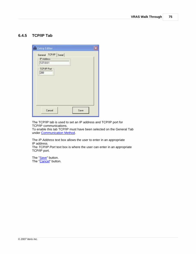
VRAS Walk Through 75
© 2007 Iteris Inc.
6.4.5 TCP/IP Tab
The TCP/IP tab is used to set an IP address and TCP/IP port forTCP/IP communications.To enable this tab TCP/IP must have been selected on the General Tabunder Communication Method.
The IP Address text box allows the user to enter in an appropriateIP address.The TCP/IP Port text box is where the user can enter in an appropriateTCP/IP port.
The "Save" button.The "Cancel" button.

The VRAS Help File76
© 2007 Iteris Inc.
6.4.6 Serial Tab
The Serial Tab is where the connection communication parameters are set.
Serial Port - Select the appropriate Serial Port.
Data Rate - Select the appropriate Data Rate (38400 is the Factory Default).
Flow Control - Select either Hardware Flow Control (RTS/CTS) or NONE(Hardware Flow control is the Factory Default).
If you are not using a modem to connect, make sure the "Use With Dial-Up Modem"check box is not checked.
See the Modem sub-section for additional information on configuring a site toconnect with VRAS using a Modem.

VRAS Walk Through 77
© 2007 Iteris Inc.
6.4.6.1 Modem
If you are using a Modem make sure you check the "Use With Dial-up Modem"check box.Under Phone Number enter in the appropriate phone number in the text box.
The "Save" button.The "Cancel" button.
For additional information on using a modem refer to the following subtopics listed below.
Dial-up Modem RequirementsModem Connections
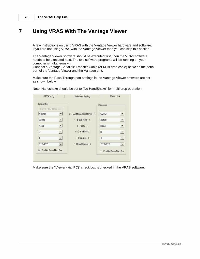
The VRAS Help File78
© 2007 Iteris Inc.
7 Using VRAS With The Vantage Viewer
A few instructions on using VRAS with the Vantage Viewer hardware and software.If you are not using VRAS with the Vantage Viewer then you can skip this section.
The Vantage Viewer software should be executed first, then the VRAS softwareneeds to be executed next. The two software programs will be running on yourcomputer simultaneously.Connect a Vantage Serial file Transfer Cable (or Multi drop cable) between the serialport of the Vantage Viewer and the Vantage unit.
Make sure the Pass Through port settings in the Vantage Viewer software are setas shown below :
Note: Handshake should be set to "No HandShake" for multi drop operation.
Make sure the "Viewer (via IPC)" check box is checked in the VRAS software.

Using VRAS With The Vantage Viewer 79
© 2007 Iteris Inc.
Everything else should be the same as any other VRAS connection scenario.

The VRAS Help File80
© 2007 Iteris Inc.
8 Troubleshooting
This error message is usually caused by :
1) No serial file transfer cable is connected to the computer serial port. See : Serial File Transfer Cable2) No modem is present, or cable is incorrect. See : Modem Connection3) Use of the wrong serial communication port.
This error message is usually caused by :
1) Wrong Unit ID (Default is "0000").2) Mismatched communication parameters. Communication parameters in theVantage unit must match those setup in the VRAS site.(Default 38400,N,Hardware) See : Serial Tab - Modem Parameters or Quick Start - Creating a Site
Multi drop Connection Problems:
The most common multi drop connection problems are caused by use of an impropermulti drop cable or forgetting to disable Hardware Flow Control where it is necessary.Another common mistake is forgetting to set unique Unit ID's for each Vantage unit inthe chain. See : Multi Drop Cable , Multi Drop Addressing
Zone Retrieval Anomaly
If you have an image on your Zone Setup screen like the one shown below afterretrieving a snapshot, then you need to set your font size to "normal". The condition iscaused when "large" font sizes are selected; resetting the font size to "normal" isthe current work around fix.

Troubleshooting 81
© 2007 Iteris Inc.
Or if your Start-up screen looks like the one below, make sure you change yourFont Size to "normal".
CAUTION : Never attempt to draw zones or send a configuration to a Vantage unitwith a snapshot that has abnormalities like the one shown above. There is a potentialfor the whole configuration to become corrupted.
Go to Display Properties / Settings / Advanced / "Normal Size" (96 DPI) for Win XP orDisplay Properties / Settings / Advanced / General / "Small Fonts" for Win 98 to changethe Font size property to "Normal Size" (96 DPI) or "small" instead of "large" or "extra large".

The VRAS Help File82
© 2007 Iteris Inc.
********************************************************************************************************
Please know that we have made every effort to try and deliver software that is stable,dependable, functional, and that will run on all the more recent MS Windows platforms.
Please report any unresolved issues, incompatibilities, or software flawsto the factory Vantage Product Support Team. We are genuinely interested in solvingany issues that you might encounter. Also, please give us your feedback and suggestionson how we might improve or Vantage products to better meet your needs and wantsin the future.
Whenever you have questions or are having difficulties, please do not hesitate to contactyour local Vantage Dealer or feel free to contact our factory Vantage Product Support Teamdirectly. We are readily available to assist you.
Other References 83
© 2007 Iteris Inc.
9 Other References
This VRAS Help file was not intended to be an all inclusive reference to theoperation of the Vantage products; instead it was intended to deal primarilywith the functionality of the VRAS software program. For specific and detailedinformation on the installation and operation of specific Vantage products orsoftware, please refer to that products Installation and User Guide.
Some of the other available product documentation:
Vantage One Installation and User GuideVantage Plus Installation and User GuideVantage Classic Edge Installation and User GuideVantage Edge2 Installation and User GuideVantage Edge2-4 Installation and User GuideVantage Wireless Installation and User GuideVantage Express Software Users ManualVantage Access Installation and User GuideVantage eAccess Installation and User GuideVantage IO Module Installation and User GuideVantage IOM-32 Installation and User GuideVantage TS2-IM Module Installation and User Guide

The VRAS Help File84
© 2007 Iteris Inc.
10 Product Support Contact Information
Vantage Product Support Team Contact InformationThe Iteris Vantage Product Support Team consists of a group of highly skilled individualsthat are knowledgeable and readily available to answer your questions or assist you withany of our Vantage products. Please do not hesitate to contact us.
Iteris Vantage Product Support Team: 888-254-5487
For more information on Iteris and the products and services that we provide, visit ourIteris Web Page at www.iteris.com
Thank you for your loyal support of our Vantage products.

Index 85
© 2007 Iteris Inc.
Index- A -acquire snapshot 38, 42
add 30
addressing 16
all 55
- B -bin 56, 57
bin all 55
bin interval 57
bin last 56
bin new 56
bin reset 55
bin today 56
bin yesterday 56
- C -camera sensitivity 52
cancel 31, 73
channel status 39
clear 57
clear display 57
clear zones 40
clock 62
clone configuration 49
communications failed 80
connect 29
connection direct connect 13
connection fiber 15
connection methods 12
connection multi drop 16
contact information 84
continuous mode 39
controls 44
counts overlay 64
creating site 19
- D -data file 73
data string 54
detection 34
detection status 34
direct 13
display mode 68
- E -edit 31
edit site 30
entry editor screen 72
exit 27
- F -fiber 15
file tranfer cable 10
firmware requirements 11
firmware version 11
- G -general tab 74
glare output 52
- H -help 84
help screen 24
- I -inactive channel 63
interval 57
IOM-32 status 36
IPC 78
- L -labels 43
last 56

The VRAS Help File86
© 2007 Iteris Inc.
LC Out Channel 52
LC Output 52
LC threshold 70
legal notices 6
load configuration
l 48
load snapshot 38, 42
- M -main 31
main menu 31
manuals 83
max 63
max recall 63
modem 14, 77
multi drop 16
muti drop cable 17
muti drrop 16
- N -new configuration 71
non-packetized 37, 42
- O -off-line configuration 25
option 52
other references 83
output overlay On / Off 65
- P -packetized 37, 42
pass through 78
pass thru 78
product support 84
- Q -quick start 18
- R -recall 63
references 83
remote access 25
remove 31
requirements cable 10
requirements computer 8
requirements modem 9
reset extension module 61
reset processor 60
retrieve configuration 48
retrieve data 54
- S -save 31, 73
save configuration 49
save data 58
save snapshot 39, 48
save snapshot w/ zones 48
screen general status 32
screen main 23
screen site list 28
screen start-up 23
send configuration 48
sensitivity 52
serial tab 76
set time 61
setup screen 40
site 19
site configuration 23
site list 28
snapshot 48
snapshot problems 80
sync 62
synchronize time 62
system labels 43
- T -TCP/IP tab 75
timestamp 64
TOD schedule 50, 69
today 56
troubleshooting 80
TS2-IM status 35

Index 87
© 2007 Iteris Inc.
- U -Unit ID 60
utilities 59
utilities screen 59
- V -vantage viewer 78
video output 65, 68
video output On / Off 65
video transfer 37, 42
view zone calls 52
viewer 78
viewer settings 78
vlock output 53
VRAS requirements 7
- W -walk through 22
welcome 5
- Y -yesterday 56
- Z -zone color 51
zone configuration 46
zone controls 44
zone labels 43
zone reset 62