variable voltage variable frequency speed control … voltage variable frequency speed control of...
TRANSCRIPT
International Research Journal of Engineering and Technology (IRJET) e-ISSN: 2395 -0056
Volume: 02 Issue: 03 | July-2015 www.irjet.net p-ISSN: 2395-0072
© 2015, IRJET.NET- All Rights Reserved Page 1268
Variable Voltage Variable Frequency Speed Control of Induction Motor Using FPGA-Xilinx
Ravi Prakash1, Prof. Rishi Kumar Singh2, Rajeev Ranjan Kumar3
1Ravi Prakash,Department of Electrical Engineering, Maulana Azad National Institute of Technology Bhopal, MP, India
2Professor Rishi Kumar Singh, Department of Electrical Engineering, Maulana Azad National Institute of Technology Bhopal, MP, India
3 MTech Scholar, Rajeev Ranjan Kumar, Department of Energy Center, Maulana Azad National Institute of Technology Bhopal, MP, India
---------------------------------------------------------------------***---------------------------------------------------------------------
Abstract - In the proposed method, the controlling
scheme is made using Xilinx. As v/f method of speed
control of induction motor is one of the mostly used
methods for speed control. In the simulation all
realistic components of the drive system has been
included. This enables to analyze and calculate the
different parameters like voltage and current in
different parts of the converter and performance of
three phase induction motor under steady state and
transient condition. A closed loop control system with
a Proportional Integral (PI) controller in the speed
control loop has designed to operate in constant
torque region. Performance characteristic of two
levels inverter fed induction motor drive is analyzed.
Open loop control of Induction motor (IM) is used in
this inverter scheme. The analysis has been done in
terms of THD in their line current. Steady state
response of speed, current and torque in induction
motor are also obtained using this scheme. Model is
developed for SPWM inverter fed induction motor
using Xilinx.
Key Words: Key PI, IM, THD, SPWM
1. INTRODUCTION Majority of industrial drives use AC induction motor because these motors are rugged, reliable, and relatively inexpensive. Three-phase induction motors are now widely used in elevator and vehicle applications for decades because of its relatively simple structure, maintenance free operation and ability to start directly from the supply network [1]. However, such an on-line starting consumes energy more than necessary and starts and stops become jerky as the motor can only be controlled with switches and relays. Three-phase induction motors are widely used in high-performance drives. Due to flexible control strategies,
application is majorly involved in variable speed drives such as high speed and low speed hoist industrial drives etc. Variable voltage variable frequency control of three-phase induction motor in closed loop is the significant feature of the thesis work. The control strategy is made by using Xilinx. Firstly three-phase induction motor drive system is simulated in various modes using Matlab/Xilinx, then finally closed loop control of induction motor is simulated using v/f method. The simulation parameters are taken based on theoretical concept of the drive system. This enables the calculation of speed, torque, voltages and currents in different parts of the system under transient and steady state conditions [2].
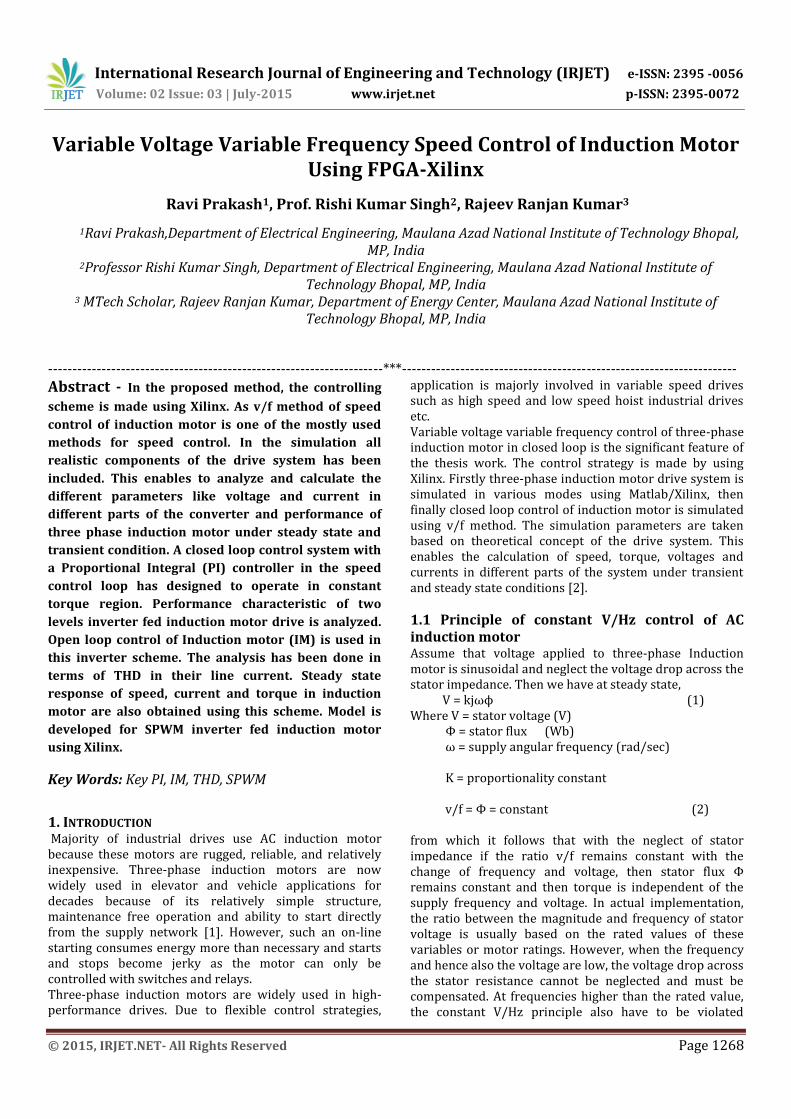
1.1 Principle of constant V/Hz control of AC induction motor Assume that voltage applied to three-phase Induction motor is sinusoidal and neglect the voltage drop across the stator impedance. Then we have at steady state, V = kjωϕ (1) Where V = stator voltage (V) Φ = stator flux (Wb) ω = supply angular frequency (rad/sec) K = proportionality constant v/f = Φ = constant (2) from which it follows that with the neglect of stator impedance if the ratio v/f remains constant with the change of frequency and voltage, then stator flux Φ remains constant and then torque is independent of the supply frequency and voltage. In actual implementation, the ratio between the magnitude and frequency of stator voltage is usually based on the rated values of these variables or motor ratings. However, when the frequency and hence also the voltage are low, the voltage drop across the stator resistance cannot be neglected and must be compensated. At frequencies higher than the rated value, the constant V/Hz principle also have to be violated
International Research Journal of Engineering and Technology (IRJET) e-ISSN: 2395 -0056
Volume: 02 Issue: 03 | July-2015 www.irjet.net p-ISSN: 2395-0072
© 2015, IRJET.NET- All Rights Reserved Page 1269
because, to avoid insulation break down, the stator voltage must not exceed its rated value. This principle is illustrated in fig 1.
Fig -1: Voltage versus frequency under the constant V/Hz principle
1.2 CLOSED LOOP CONTROL OF THREE-PHASE INDUCTION Here in the proposed scheme firstly three-phase induction motor is fed by three-phase voltage source inverter in open loop, in which sine pulse width modulation technique is used for generating the controlling waveform. The control strategy is made by using Xilinx[3]. Here in first case the induction motor is fed without any filter by taking the following values of mf and ma. Amplitude modulation index (ma) = 0.8 Frequency modulation index (mf) = 27 The line current THD is 11.3%. The torque ripple is also too much. So to reduce line current THD, a Second Order low pass filter is used in between VSI and Induction Motor with parameters given below. Damping factor (ξ) = 0.707 Cutoff frequency (ω) =2π*300 rad/sec The general block diagram for closed loop control of three-phase induction motor is shown in fig. 2.7. For making closed loop control of v/f control, fundamental component of line to line voltage is taken and subtracted it from reference voltage to obtain error voltage, this error voltage is fed to PI controller. The output of PI Controller is then used for changing the value of ‘ma’ and ‘mf’, for changing the magnitude of input voltage of induction motor and frequency respectively. The output of PI Controller is always an integer value, which is the main feature of PI Controller using FPGA. However sometimes there is fluctuation of one or two unit occurs due to which
the ripple in torque occurs, but it can occur only at low frequency [4].
PWM
CONTROLLER
USING XILINX
VOLTAGE
SOURCE
INVERTER
SECOND
ORDER LOW
PASS
FILTER
THREE-
PHASE
SQUIRREL
INDUCTION
MOTOR
VOLTMETER
FUNDAMENTAL
COMPONENT OF
LINE TO LINE
VOLTAGE
REFERENCE
VOLTAGE
PI CONTROLLER
USING XILINX
CONTROL SIGNALS
FOR CHANGING
THE VALUE OF mf
AND ma
-
+
ERROR
VOLTAGE
CONSTANT
LOAD
TORQUE
mf
ma
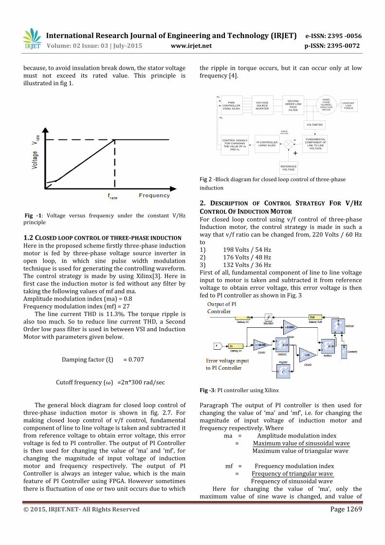
Fig 2 -Block diagram for closed loop control of three-phase
induction
2. DESCRIPTION OF CONTROL STRATEGY FOR V/HZ
CONTROL OF INDUCTION MOTOR For closed loop control using v/f control of three-phase Induction motor, the control strategy is made in such a way that v/f ratio can be changed from, 220 Volts / 60 Hz to 1) 198 Volts / 54 Hz 2) 176 Volts / 48 Hz 3) 132 Volts / 36 Hz First of all, fundamental component of line to line voltage input to motor is taken and subtracted it from reference voltage to obtain error voltage, this error voltage is then fed to PI controller as shown in Fig. 3
Fig -3: PI controller using Xilinx
Paragraph The output of PI controller is then used for changing the value of ‘ma’ and ‘mf’, i.e. for changing the magnitude of input voltage of induction motor and frequency respectively. Where ma = Amplitude modulation index = Maximum value of sinusoidal wave Maximum value of triangular wave mf = Frequency modulation index = Frequency of triangular wave Frequency of sinusoidal wave Here for changing the value of ‘ma’, only the maximum value of sine wave is changed, and value of
International Research Journal of Engineering and Technology (IRJET) e-ISSN: 2395 -0056
Volume: 02 Issue: 03 | July-2015 www.irjet.net p-ISSN: 2395-0072
© 2015, IRJET.NET- All Rights Reserved Page 1270
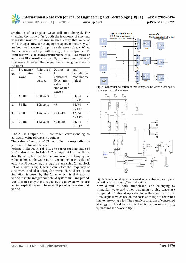
amplitude of triangular wave will not changed. For changing the value of ‘mf’, both the frequency of sine and triangular wave will change in such a way that value of ‘mf’ is integer. Now for changing the speed of motor by v/f method, we have to change the reference voltage. When the reference voltage will change, the output of PI controller will also change proportionally [5]. The value of output of PI controller is actually the maximum value of sine wave. However the magnitude of triangular wave is ’64 units’ S.
no.
Frequency of sine wave
Reference line to line voltage
Output of PI Controller (Maximum value of sine of sine wave )
‘ma’ (Amplitude modulation index)
1. 60 Hz 220 volts 53 53/64 =
0.8281
2. 54 Hz 198 volts 46 46/64 =
0.7187
3. 48 Hz 176 volts 42 to 43 42/64 =
0.6562
4. 36 Hz 132 volts 40 to 38 38/64 =
0.5937
. Table -1: Output of PI controller corresponding to particular value of reference voltage The value of output of PI controller corresponding to particular value of reference Voltage is shown in Table 1. The corresponding value of ‘ma’ is also shown in Table 1. The output of PI controller is directly multiplied to reference sine wave for changing the value of ‘ma’ as shown in fig 4. Depending on the value of output of PI controller, the logic is made using Xilinx block set as shown in fig. 4, which can select the frequency of sine wave and also triangular wave. Here there is the limitation imposed by the Xilinx which is that explicit period must be integer multiple of system simulink period. Due to which only those frequency are allowed, which are having explicit period integer multiple of system simulink period.
Fig -4: Controller Selection of frequency of sine wave & change in the magnitude of sine wave.
Fig -5: Simulation diagram of closed loop control of three-phase induction motor using v/f control method.
Now output of both multiplexer, one belonging to triangular wave and other belonging to sine wave are compared in ‘Rational’ operator, for getting controlled sine PWM signals which are on the basis of change of reference line to line voltage [6]. The complete diagram of controlled strategy of closed loop control of induction motor using v/f method is shown in fig. 6.
International Research Journal of Engineering and Technology (IRJET) e-ISSN: 2395 -0056
Volume: 02 Issue: 03 | July-2015 www.irjet.net p-ISSN: 2395-0072
© 2015, IRJET.NET- All Rights Reserved Page 1271
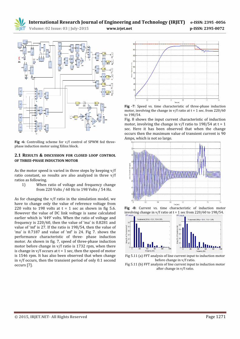
Fig -6: Controlling scheme for v/f control of SPWM fed three-phase induction motor using Xilinx block.
2.1 RESULTS & DISCUSSION FOR CLOSED LOOP CONTROL
OF THREE-PHASE INDUCTION MOTOR As the motor speed is varied in three steps by keeping v/f ratio constant, so results are also analyzed in three v/f ratios as following.
1) When ratio of voltage and frequency change from 220 Volts / 60 Hz to 198 Volts / 54 Hz.
As for changing the v/f ratio in the simulation model, we have to change only the value of reference voltage from 220 volts to 198 volts at t = 1 sec as shown in fig 5.6. However the value of DC link voltage is same calculated earlier which is ‘449’ volts. When the ratio of voltage and frequency is 220/60, then the value of ‘ma’ is 0.8281 and value of ‘mf’ is 27. If the ratio is 198/54, then the value of ‘ma’ is 0.7187 and value of ‘mf’ is 24. Fig 7. shows the performance characteristic of three- phase induction motor. As shown in fig. 7, speed of three-phase induction motor before change in v/f ratio is 1732 rpm, when there is change in v/f occurs at t = 1 sec, then the speed of motor is 1546 rpm. It has also been observed that when change in v/f occurs, then the transient period of only 0.1 second occurs [7].
Fig -7: Speed vs. time characteristic of three-phase induction motor, involving the change in v/f ratio at t = 1 sec. from 220/60 to 198/54. Fig. 8 shows the input current characteristic of induction motor, involving the change in v/f ratio to 198/54 at t = 1 sec. Here it has been observed that when the change occurs then the maximum value of transient current is 90 Amps, which is not so large.
Fig -8: Current vs. time characteristic of induction motor involving change in v/f ratio at t = 1 sec from 220/60 to 198/54.
Fig 5.11 (a) FFT analysis of line current input to induction motor
before change in v/f ratio. Fig 5.11 (b) FFT analysis of line current input to induction motor
after change in v/f ratio.
International Research Journal of Engineering and Technology (IRJET) e-ISSN: 2395 -0056
Volume: 02 Issue: 03 | July-2015 www.irjet.net p-ISSN: 2395-0072
© 2015, IRJET.NET- All Rights Reserved Page 1272
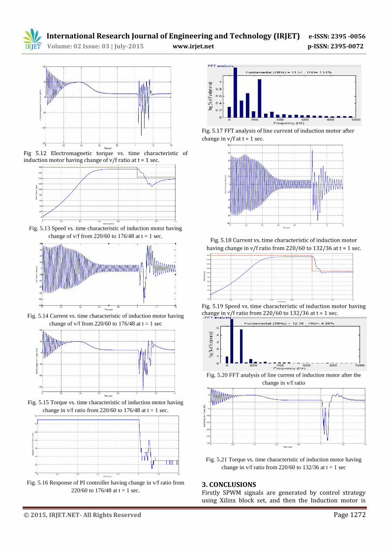
Fig 5.12 Electromagnetic torque vs. time characteristic of induction motor having change of v/f ratio at t = 1 sec.
Fig. 5.13 Speed vs. time characteristic of induction motor having
change of v/f from 220/60 to 176/48 at t = 1 sec.
Fig. 5.14 Current vs. time characteristic of induction motor having
change of v/f from 220/60 to 176/48 at t = 1 sec
Fig. 5.15 Torque vs. time characteristic of induction motor having
change in v/f ratio from 220/60 to 176/48 at t = 1 sec.
Fig. 5.16 Response of PI controller having change in v/f ratio from
220/60 to 176/48 at t = 1 sec.
Fig. 5.17 FFT analysis of line current of induction motor after
change in v/f at t = 1 sec.
Fig. 5.18 Current vs. time characteristic of induction motor
having change in v/f ratio from 220/60 to 132/36 at t = 1 sec.
Fig. 5.19 Speed vs. time characteristic of induction motor having change in v/f ratio from 220/60 to 132/36 at t = 1 sec.
Fig. 5.20 FFT analysis of line current of induction motor after the
change in v/f ratio
Fig. 5.21 Torque vs. time characteristic of induction motor having
change in v/f ratio from 220/60 to 132/36 at t = 1 sec
3. CONCLUSIONS Firstly SPWM signals are generated by control strategy using Xilinx block set, and then the Induction motor is
International Research Journal of Engineering and Technology (IRJET) e-ISSN: 2395 -0056
Volume: 02 Issue: 03 | July-2015 www.irjet.net p-ISSN: 2395-0072
© 2015, IRJET.NET- All Rights Reserved Page 1273
simulated in open loop using Matlab/Simulink. But the performance of induction motor is not satisfactory. For mf = 27, and ma = 0.8, line current THD of VSI fed three-phase induction motor without using filter is 12.91%. Due to which the torque ripple and losses in system are also high. By using second order Filter (ω=300*2*pi and ξ=0.4), line current THD decreases to 1.35%.
REFERENCES [1] [1] Nabae, I. Takahashi and H. Agaki, “A New Neutral-
Point-Clamped PWM Inverter,” IEEE Transactions on Industry Applicaitions. Vol.IA-17, No.5, Sep./Oct., 1981, pp.518-523.
[2] R. Nandhakumar, S. Jeevananthan and P. Dananjayan, “Design and Implementation of an FPGA Based High Performance ASIC for Open Loop PWM Inverter,” IICPE, 2006, pp.349-354
[3] Reddy M. H. V. and Jegathesan V., “Open loop V/f control of induction motor based on hybrid PWM with reduced torque ripple,” International Conference on Emerging Trends in Electrical and Computer Technology , pp.331-336, March 2011.
[4] Arulmozhiyal, R. Baskaran, K. Devarajan and N. Kanagaraj, “Space Vector Pulse Width Modulation Based Induction Motor Speed Control Using FPGA,” ICETET, 16-18 Dec 2009, pp 242-247.
[5] A.Fratta, G. Griffero and S. Nieddu, “Comparative analysis among DSP and FPGA-based control capabilities in PWM power converters,” Proceedings of the 30th Annual Conference of the IEEE Industrial Electronics Society (IECON .04) Novemeber, pp 257-262.
[6] C. Mademlis and N. Margaris, "Loss minimization in vector-controlled induction motor drives," Industrial Electronics, IEEE Transactions on, vol. 49, pp. 1344-1347, 2002.
[7] X. Jian-Xin, S. K. Panda, P. Ya-Jun, L. Tong Heng, and B. H. Lam, "A modular control scheme for induction motor speed control with pulsating torque minimization," Industrial Electronics, IEEE Transactions on, vol. 51, pp. 526-536, 2004
[8] S. Zhang, C. Zhu, J. K. O. Sin, and P. K. T. Mok, “A novel ultrathin elevated channel low-temperature poly-Si TFT,” IEEE Electron Device Lett., vol. 20, pp. 569–571, Nov. 1999.
[9] Taro Genda, et.al, “Basic Performance of Inset Type PMSM” IEEE conference on Electrical Machine; PaperID 1422, 2008
[10] Purohit, Purnima; Dubey, Menka, "Analysis and design of hysteresis current controlled multilevel
inverter fed PMSM drive," Electrical, Electronics and
Computer Science (SCEECS), 2014 IEEE Students' Conference on, vol., no., pp.1,5, 1-2 March 2014
[11] N. Urasaki; T. Senjyu; K Uezato, “An Accurate Modeling for Permanent Magnet Synchronous Motor Drives”, Applied Power Electronics Conference and Exposition, APEC 2000, Vol. 1, 6-10 Feb. 2000, pp:387 – 392.