varmeca - elektromotori, motori, prenosnici, …kmc.co.rs/sites/default/files/varmeca...
TRANSCRIPT

VARMECA
Réf. 3267 en - 2.33 / e - 4.03
Variable speedmotors and geared motors
Selection guide

2
Variable speed motors and geared motorsDrive systems
LEROY-SOMER reserves the right to modify the design, technical specifications and dimensions of the products shown in this catalogue.The descriptions cannot in any way be considered contractual.
Cb
Gearboxtype
3333 B3 S MI57.6
Size: 33- -and manufacturer code
Operatingposition
Mountingform
1
LS 90 L
Series, frame size,manufacturer code
1.8 kW4p A1VMA 22 T180 BMA
Rated power(kW)
No. of poles: 4
Rated voltageand frequency
VARMECAposition
Option
2 3
GEARBOX
VARMECA
Possible motor options:
- drip cover
- 2nd shaft extension, etc.
- brake
Possible VARMECA options:
- BMA, BMA VAR
- CVI VMA,
- SO VMA, etc.
Gearbox options available:
- BS flange mounted
- BD flange mounted (different diameter flange)
- BT face mounted, etc.
400-480 V50-60 Hz
Exactreduction
Type of input"MI"-"MUFF"-"MUFT"
1
3
2
VARMECArating
VARIABLE SPEED MOTOR

Variable speed motors and geared motorsContents
3
Copyright 2003: LEROY-SOMER
PAGE
A - VARMECA - General information . . . . . . . . . . . . . . . . 8
A1 - Quality assurance 5
A2 - General operating principle 6
A3 - Product name 6
A4 - Characteristics 6
A5 - Environmental characteristics 7
A6 - Terminal blocks 7
A7 - Description of cables and protection devices 8
A8 - Description of the VARMECA 20 braking resistor 9
A9 - Options 9
B - VARMECA - Motor characteristics. . . . . . . . . . . . . . . 11
B1 - Selection: Single-phase power supply, ∆ connection 11
B2 - Selection: 3-phase power supply, ∆ connection 12
B3 - Selection: 3-phase power supply, Υ connection 13
B4 - Dimensions: Foot mounted 14
B5 - Dimensions: Foot and flange mounted 15
B6 - Dimensions: Flange mounted 16
B7 - Dimensions: Foot and face mounted 17
B7 - Dimensions: Face mounted 18
C - VARMECA - Geared motor characteristics . . . . . . . 19
C1 - General selection procedure and gearbox selection 19
C2 - Gearbox technology 19
C3 - Selection for gearboxes 20
C4 - Torque/speed characteristics 21
D - VARMECA + COMPABLOC 3000 . . . . . . . . . . . . . . . . 23
D1 - General 23
D2 - Construction 23
D3 - Mounting arrangements 24
D4 - Adaptation possibilities 25
D5 - Designation / Coding 25
D6 - Selection (kp factor for AGMA class I, II, III) 26 to 33
D7 - Dimensions 34 to 40
E - VARMECA + COMPABLOC 2000 . . . . . . . . . . . . . . . . 41
E1 - General 41
E2 - Construction 41
E3 - Mounting arrangements 42
E4 - Adaptation possibilities 43
E5 - Designation / Coding 43
E6 - Selection (AGMA class I kp = 1) 44
E7 - Dimensions 45 to 49
PAGE
F - VARMECA + ORTHOBLOC 2000 . . . . . . . . . . . . . . . . . 51
F1 - General 51
F2 - Construction 51
F3 - Mounting arrangements 52
F4 - Adaptation possibilities 50
F5 - Designation / Coding 53
F6 - Selection (AGMA class I kp = 1) 54
F7 - Dimensions 55 to 57
G - VARMECA + MANUBLOC 2000 . . . . . . . . . . . . . . . . . . 59
G1 - General 59
G2 - Construction 59
G3 - Mounting arrangements 60
G4 - Adaptation possibilities 61
G5 - Designation / Coding 61
G6 - Selection (AGMA class I kp = 1) 62
G7 - Dimensions 63 to 66
H - VARMECA + MULTIBLOC 2100. . . . . . . . . . . . . . . . . . 67
H1 - General 67
H2 - Construction 67
H3 - Mounting arrangements 68
H4 - Adaptation possibilities 69
H5 - Designation / Coding 69
H6 - Selection (AGMA class I kp = 1) 70
H7 - Dimensions 71 and 72
I - VARMECA + MULTIBLOC 2000 . . . . . . . . . . . . . . . . . . 73
I1 - General 73
I2 - Construction 73
I3 - Mounting arrangements 74
I4 - Adaptation possibilities 74
I5 - Designation / Coding 75
I6 - Selection (AGMA class I kp = 1) 76
I7 - Dimensions 77 to 83

4
Variable speed motors and geared motorsIndex
PAGE
A
GMA...........................................................................19Altitude ...........................................................................7Approvals ......................................................................7
B
raking resistor ..............................................................9
C
able gland ....................................................................8Cables ............................................................................8COMPABLOC 2000 .....................................................41COMPABLOC 3000 .....................................................23Connection .................................................................... 8Construction ...................................................................6
D
esignation ....................................................................6
E
lectrical characteristics.................................................6EMC ...............................................................................7Environment ...................................................................7
F
CR brake ....................................................................20Fieldbus..........................................................................9Flanges...........................................16, 23, 41, 51, 59, 73FMC brake....................................................................20Fuses..............................................................................8
G
earbox selection ........................................................19
H
umidity .........................................................................7
I
EC .................................................................................7Immunity.........................................................................7Installation .....................................................................7Insulation classification...................23, 41, 51, 59, 67, 73Interference ....................................................................7ISO .................................................................................5
Kp
duty factor ...............................................................19
M
ANUBLOC .................................................................59Mounting.........................................................................7MULTIBLOC 2000........................................................73MULTIBLOC 2100........................................................67
N
oise ..............................................................................9
O
il ...................................................23, 41, 51, 59, 67, 73Operation....................................6, 24, 42, 52, 60, 68, 74Options ...........................................................................9ORTHOBLOC...............................................................51
P
aint ...............................................23, 41, 51, 59, 67, 73Pilot control.................................................................7, 9Protection .......................................................................7
Q
uality ...........................................................................5
R
FI filter ..........................................................................9
PAGE
S
econd motor................................................................. 9Selection .......................................................... 11, 20, 26Shaft............................................... 23, 41, 51, 59, 67, 73Speed......................................................... 11, 12, 13, 21Speed variation range.............................................. 6, 21Starting.......................................................................... 6Storage .......................................................................... 7Supply voltage ............................................................... 6
T
erminal block connection ............................................ 7Terminal blocks.............................................................. 7Torque arm .................................................................. 73Torque curve................................................................ 21
UL
standard ................................................................... 7
V
ibrations....................................................................... 7
W
eight.......................................................................... 16

Variable speed motors and geared motorsVARMECA - General information
5
A1 -
Quality assurance
Industrial concerns are having to copewi th an ever more compet i t i veenvironment. Productivity depends to aconsiderable degree on the rightinvestment at the right time.LEROY-SOMER has the answer,building motors to precise standards ofquality.
When carrying out quality checks on amachine's performance, the first step isto
measure the level of customersatisfaction.
Careful study of this information tells uswhich points need looking at, improvingand monitoring.
From the moment you place your orderwith our administrative staff until themotor is up and running (after designstudies, launch and product ionactivities) we keep you informed andinvolved.
Our own processes are constantlyunder review. All our staff are involvedin both operational process analysisand continuous training programmes.These initiatives help them serve youbetter, and increased skills bringincreased motivation.
At LEROY-SOMER, we think it vital forour customers to know the importancewe attach to quality.
LEROY-SOMER has entrusted thecertification of its expertise to variousinternational organisations.Certification is granted by indepen-dent professional auditors, and re-cognises the high standards of the
company's quality assurance pro-cedures.
All activities resulting in the final ver-sion of the machine have thereforereceived official ISO 9000 accre-ditation. Products are alsoapproved by official bo-dies who inspect theirtechnical performancewith regard to the var-ious standards.This is a fundamentalrequirement for a com-pany of internationalstanding.

6
Variable speed motors and geared motorsVARMECA - General information
VARMECA is the physical association of a3-phase induction motor and an integratedvariable speed drive.
The motor allows all kinds of mountingarrangements (foot or flange) and can becombined with standard gearboxes from theLEROY-SOMER range.
eg: VMA-A21TL-075
- 21: Short casing M : Single-phase power supply 200 - 240 V ±10%; 50/60 Hz ±10% 22: Long casing TL : 3-phase power supply 200 - 240 V ±10%; 50/60 Hz ±10% T : 3-phase power supply 380 - 480 V ±10%; 50/60 Hz ±10%
*
VMA 14: 3-phase power supply 400 - 440 V ±10%; 50/60 Hz ±10%
*
VMA 14: 3-phase power supply 400-440V ±10%; 50/60 Hz ±10%
Ramps Increment Fmax. Functions & Configurations (
≠
)
VMA A 21-22 100 s 1 s 220 Hz PI Regulation, Pump Control (see doc. ref. 3532 section 2.5 - p.14, config. 5)
VMA B 21-22 40 s 0.1 s 100 HzTorque limiter, Faster/Slower, Dynamic Control (see doc. ref. 3532section 2.5 - p.14, config. 7),VMAESFR card adaptation
VMA 14 * 20 s 1 s 220 Hz PI Regulation
VARMECA
200/240V single-phase power supply 200/240V 3-phase power supply 400/480V 3-phase power supply
VMA rating Power (kW) VMA rating Power (kW) VMA rating Power (kW)
A or B 21M - 025 0.25 A or B 21TL - 025 0.25 A or B 21T - 025 0.25
A or B 21M - 037 0.37 A or B 21TL - 037 0.37 A or B 21T - 037 0.37
A or B 21M - 055 0.55 A or B 21TL - 055 0.55 A or B 21T - 055 0.55
A or B 21M - 075 0.75 A or B 21TL - 075 0.75 A or B 21T - 075 0.75
A or B 22M - 090 0.9 A or B 22TL - 090 0.9 A or B 21T - 090 0.9
A or B 22M - 110 1.1 A or B 22TL - 110 1.1 A or B 21T - 110 1.1
A or B 22M - 150 1.5 A or B 22TL - 150 1.5 A or B 22T - 150 1.5
- A or B 22TL - 180 1.8 A or B 22T - 180 1.8
- A or B 22TL - 220 2.2 A or B 22T - 220 2.2
- - - A or B 22T - 300 3
- - - A or B 22T - 400 4
- - - 14 - 550* 5.5
- - - 14 - 750* 7.5
Characteristics VARMECA
Overload 150% of In for 40s, 10 times per hour
Motor frequency variation range - from 12 to 80 Hz at constant torque- from 12 to 50 Hz for general applications- from 6 to 220 Hz (VARMECA A20 and 14) or from 6 to 100 Hz (VARMECA B20)
Efficiency 97.5% x motor efficiency
Maximum number of power-ups per hour Single-phase power supply: 103-phase power supply: unlimited
A2 - General operating principle
A3 - Product name
A4 - Characteristics

Variable speed motors and geared motorsVARMECA - General information
7
A5 - Environmental characteristics
CharacteristicsLevel
VMA 21 -22 VMA 14
Protection index IP 65 IP 55
Storage temperature -40°C to +70°C (IEC 68.2.3) -40°C to +70°C (IEC 68.2.3)
Transport temperature -40°C to +70°C -40°C to +70°C
Operating temperature -20°C to +40°C (+50°C with derating) -20°C to +40°C (+50°C with derating)
Altitude
≤
1000m without derating
≤
1000m without derating
Ambient humidity Without condensation Without condensation
Vibration IEC 68-2-34 (acceleration 0.01 g
2
/Hz) IEC 68-2-34 (acceleration 0.01 g
2
/Hz)Shocks IEC 68-2-27 (peak acceleration 20g) IEC 68-2-27 (peak acceleration 20g)
Immunity Conforming to EN 50082-2 level 4 Conforming to EN 50082-2 level 4
Radiated conducted emissions • Conforming to EN 50081-2 as standard• Conforming to EN 50081-1 with EMC filter option for the VMA 21 M range
Conforming to EN 50081-2 with EMC filter option
UL standard Conforming to FILE E211799 Not tested
Terminal layout P1 terminal block (standard configuration)
Max. cross-section: 2.5 m
2
ON
K3 K2
P2
P1
P3
K1
OFF
1 2 3 4 5 6 7 8 9 10 11 12 L1 L2 L3 PE R+ R-
Control/Command Mains supply
M/N : 77b3000AP/N : VARMECA21S/N : 20106000748
Marking Functions - Characteristics
Connection of protected mains supply phases
L1, L2 Single-phase
L1, L2, L3 3-phase
PE Earth connection
R1, R2 Braking resistor connection
1 Drive locking logic input
2Speed analogue output 0/10V, 3mA
Analogue input: 0/10V or 4/20 mA
3 Source +24V, 30mA (± 10%)
4 Source +10V, 3mA (± 10%)
5 0V - Connected to the casing earth
6 Reference input 0/10V or 4/20mA
7 Reverse/Stop logic input
8 Forward/Stop logic input
9 Ramp selection logic input
10 Source +24V, 30mA (± 10%)
11, 12 Fault relay - normally closed contact 1A
A6 - Terminal blocks

8
Variable speed motors and geared motorsVARMECA - General information
*
VMA 14: 3-phase power supply 400-440V ±10%; 50/60 Hz ±10%
Note:
• The mains current value is a typical value which depends on the source impedance. The higher the impedance, the lower the current.• The fuses (UL approved) are intended for installations capable of delivering 5000A maximum at 480V.
Polyamide anchoring cable gland
Cable gland clamping capacity (Standards NFEN 50 262)
Dimensions in millimetres
P(kW)
200/240V single-phase power supply 200/240V 3-phase power supply 400/480V 3-phase power supply
VMA ratingI
gI fusesCables
VMA ratingI
gI fusesCables
VMA ratingI
gI fusesCablesor circuit- or circuit- or circuit-
breaker breaker breaker(A) (A) (mm
2
) (A) (A) (mm
2
) (A) (A) (mm
2
)
0.25 A or B 21M-025 3.5 8 1.5 A or B 21TL-025 2 4 1.5 A or B 21T-025 1 4 1.5
0.37 A or B 21M-037 4 10 1.5 A or B 21TL-037 3 6 1.5 A or B 21T-037 1.5 4 1.5
0.55 A or B 21M-055 4.5 10 1.5 A or B 21TL-055 4 6 1.5 A or B 21T-055 2 6 1.5
0.75 A or B 21M-075 7 16 2.5 A or B 21TL-075 5 8 1.5 A or B 21T-075 3 6 1.5
0.9 A or B 22M-090 9 16 2.5 A or B 22TL-090 5.5 10 1.5 A or B 21T-090 3.5 8 1.5
1.1 A or B 22M-110 11 20 2.5 A or B 22TL-110 6 10 1.5 A or B 21T-110 4 10 1.5
1.5 A or B 22M-150 14 25 2.5 A or B 22TL-150 7 16 2.5 A or B 22T-150 5 10 1.5
1.8 - - - - A or B 22TL-180 7.5 16 2.5 A or B 22T-180 5.5 10 2.5
2.2 - - - - A or B 22TL-220 8 16 2.5 A or B 22T-220 6 10 2.5
3 - - - - - - - - A or B 22T-300 7 16 2.5
4 - - - - - - - - A or B 22T-400 8 16 2.5
5.5 - - - - - - - - 14,550* 13 16 2.5
7.5 - - - - - - - - 14,750* 16 20 4
VARMECA rating Type of CABLE GLAND
VMA 21 - 22 ISO 16 and ISO 20
VMA 14 ISO 16 and ISO 25
Type of cable gland
POLYAMIDE anchoring cable gland
Clamping capacity Length
MIN. cable ø MAX. cable ø L
ISO 16 6 10 17
ISO 20 10 15 17
ISO 25 13 19 17
• When using a circuit-breaker, itmust be a motor circuit-breaker (Dcurve).
• Comply with the size of protectionfuses.
• The cable size may vary according tolegislation applicable in the country,which will take precedence over thevalues in the tables below.
• These tables should never be usedinstead of current standards.
A7 - Description of cables and protection devices
Ø m
in.
Ø m
ax.
L
Polyamide anchoring cable gland

Variable speed motors and geared motorsVARMECA - General information
9
For operation in 4 quadrants and energydissipation, resistors are fixed directly ontothe VARMECA casing.
In frame size 132, the VARMECA 14 is supplied as standard with a control button (BD: button on the left, cable gland on the right - BG: button on the right, cable gland on the left - SD: no button, cable gland on the right - SG: no button, cable gland on the left)
Key: in offer not availableM : single-phase VMA power supplyTL : 3-phase VMA power supplyT : 3-phase VMA power supply
VARMECA VMA 21 - 22 VMA 14
Designation Description M TL T T
B Integrated speed control knob
BMA Integrated speed control and run-stop control knob
NA
BMAVAR Integrated speed control knob and forward-stop/reverse-stop control
NA
CVI VMA 20 Integrated speed settings
NA
FLT VMA 14 RFI filter NA NA NA
FLT VMA 21 M Class B EMC filter (domestic level) - Single-phase supply
NA NA NA
RF100 - RF200 Braking resistors. Power 100 and 200W
NA
SO VMA Fixed brake control and power supply - 3-phase supply NA NA
NA
VMA ESFR Additional I/O interface and sequential brake control
NA
CDC VMA 10 VARMECA console NA NA NA
CDC VMA 20 VARMECA console
NA
PEGASE VMA 10 VARMECA PC software NA NA NA
PEGASE VMA 20 VARMECA PC software
NA
VMA COM PB Fieldbus: PROFIBUS DP
NA
VMA COM IS Fieldbus: INTERBUS S
NA
VMA COM DT Fieldbus: DEVICENET
NA
VMA COM CN Fieldbus: CAN OPEN
NA
POT 10K 1T 1-turn 10 K Ohm potentiometer
POT 10 K 10T 10-turn 10 K Ohm potentiometer
LEC VMA Digital display for remote reading
FLASQUE 4 PE 4 PE shield for supplying a 2nd motor
NA
NA
External resistors with greater thermal power can be used, provided that the minimum ohmicvalue is respected.
RF 100 RF 200
Ppeak
Pthermal
ValueP
peakP
thermalValue
kW W
Ω
kW W
Ω
VMA A or B 21T 2.8
100 200
2.8
200
200(2x100
inseries)
VMA A or B 21M/TL 0.65 0.65
VMA A or B 22T 2.8 2.8
VMA A or B 22M/TL 0.65 0.65
A8 - Description of the VARMECA 20 braking resistor
A9 - Options

10
Variable speed motors and geared motorsVARMECA - General information

Variable speed motorsVARMECA - Motor characteristics
11
SINGLE-PHASE POWER SUPPLY: 200V -10% to 240V +10%, 50/60Hz ±10%3-phase motors 230V/400V ±10%
∆
CONNECTEDTorque/speed characteristics of 2, 4 and 6-pole motors
* Either version A or B
* Either version A or B
* Either version A or B
Key:M
N:
rated torque - M
D:
starting torque - F
d:
switching frequency
Measured torque (N.m)/Speed (min
-1
)M
D
(Nm)F
d
(kHz)Rated torque at 3000 min
-1
Speeds
Type M
N
600 900 1200 1500 1800 2200 2400 3000 3600
2 P - LS 71 0.25 kW - VMA *21M 025
0.8 0.6 0.6 0.7 0.7 0.8 0.8 0.8 0.8 0.6 1.6 11
2 P - LS 71 0.37 kW - VMA *21M 037
1.2 0.8 1 1.1 1.2 1.2 1.2 1.2 1.2 1 1.9 11
2 P - LS 71 0.55 kW - VMA *21M 055
1.8 1.2 1.4 1.6 1.7 1.8 1.8 1.8 1.8 1.5 3.6 11
2 P - LS 80 L 0.75 kW - VMA *21M 075
2.4 2 2 2.2 2.2 2.3 2.5 2.5 2.4 2 4.5 11
2 P - LS 80 L 1.1 kW - VMA *22M 110
3.5 3 3.1 3.3 3.3 3.3 3.6 3.8 3.6 2.9 8 11
2 P - LS 90 S 1.5 kW - VMA *22M 150
4.8 4 4 4 4.1 4.1 4.3 4.8 4.8 4 9 8
Measured torque (N.m)/Speed (min
-1
)M
D
(Nm)F
d
(kHz)Rated torque at 1500 min
-1
Speeds
Type M
N
320 600 900 1200 1500 1800 2200
4 P - LS 71 0.25 kW - VMA *21M 025
1.6 1.1 1.2 1.3 1.5 1.6 1.4 1.1 2.4 11
4 P - LS 71 0.37 kW - VMA *21M 037
2.4 1.6 1.8 1.9 2.2 2.4 2 1.6 4.8 11
4 P - LS 71 0.55 kW - VMA *21M 055
3.6 2.2 2.6 2.8 3.2 3.6 2.9 2.4 7.2 11
4 P - LS 80 L 0.75 kW - VMA *21M 075
4.8 3 4 4.4 4.4 4.8 4 3 10 11
4 P - LS 80 L 0.9 kW - VMA *22M 090
5.7 4 4.8 5.4 5.7 5.7 4.8 4 11 11
4 P - LS 90 S 1.1 kW - VMA *22M 110
7 4.7 5.3 6.7 7 7 5.8 4.4 13 11
4 P - LS 90 L 1.5 kW - VMA *22M 150
9.5 6.7 8.2 9.1 9.5 9.5 7.8 6.2 18 8
Measured torque (N.m)/Speed (min
-1
)M
D
(Nm)F
d
(kHz)Rated torque at 1000 min
-1
Speeds
Type M
N
200 400 600 1000 1200 1500
6 P - LS 80 L 0.25 kW - VMA *21M 025
2.4 2.2 2.4 2.4 2.4 2 1.7 8 11
6 P - LS 80 L 0.37 kW - VMA *21M 055
3.5 3.1 3.4 3.7 3.8 3.2 2.6 10 11
6 P - LS 80 L 0.55 kW - VMA *21M 075
5.3 4.3 4.9 5.3 5.3 4.8 4.3 13 11
6 P - LS 90 S 0.75 kW - VMA *22M 090
7.2 6.8 6.8 7.2 7.6 6.3 4.8 16 11
6 P - LS 90 L 1.1 kW - VMA *22M 150
10.5 7.7 7.7 8.7 10.5 8.7 6.7 20 8
B1 - Selection: Single-phase power supply,
∆
connection
2poles3000 min-1
4poles1500 min-1
6poles1000 min-1

12
Variable speed motorsVARMECA - Motor characteristics
3-PHASE POWER SUPPLY: 200V -10% to 240V +10%, 50/60Hz ±10%3-phase motors 230V/400V ±10%
∆
CONNECTEDTorque/speed characteristics of 2, 4 and 6-pole motors
* Either version A or B
* Either version A or B
* Either version A or B
Key:M
N:
rated torque - M
D:
starting torque - F
d:
switching frequency
Measured torque (N.m)/Speed (min
-1
)M
D
(Nm)F
d
(kHz)Rated torque at 3000 min
-1
Speeds
Type M
N
600 900 1200 1500 1800 2200 2400 3000 3600
2 P - LS 71 0.25 kW - VMA *21TL 025
0.8 0.6 0.6 0.7 0.7 0.8 0.8 0.8 0.8 0.7 1.6 11
2 P - LS 71 0.37 kW - VMA *21TL 037
1.2 0.8 1 1.1 1.2 1.2 1.2 1.2 1.2 1 1.9 11
2 P - LS 71 0.55 kW - VMA *21TL 055
1.8 1.2 1.4 1.6 1.7 1.8 1.8 1.8 1.8 1.5 3.6 11
2 P - LS 80 L 0.75 kW - VMA *21TL 075
2.4 2.1 2.1 2.3 2.4 2.5 2.7 2.7 2.6 2 4.5 8
2 P - LS 80 L 1.1 kW - VMA *22TL 110
3.5 3.3 3.3 3.5 3.5 3.5 3.8 3.8 3.8 2.9 8 8
2 P - LS 90 S 1.5 kW - VMA *22TL 150
4.8 4 4 4.3 4.3 4.3 4.5 4.5 4.8 4 9 6
2 P - LS 90 L 1.8 kW - VMA *22TL 180
5.7 5.5 5.5 5.8 5.8 6 6 6.2 6.2 4.8 12 4
2 P - LS 90 L 2.2 kW - VMA *22TL 220
7 7 7 7.2 7.5 7.5 7.5 7.5 7.5 6 12 4
Measured torque (N.m)/Speed (min
-1
)M
D
(Nm)F
d
(kHz)Rated torque at 1500 min
-1
Speeds
Type M
N
320 600 900 1200 1500 1800 2200
4 P - LS 71 0.25 kW - VMA *21TL 025
1.6 1.1 1.2 1.3 1.5 1.6 1.4 1.1 2.4 11
4 P - LS 71 0.37 kW - VMA *21TL 037
2.4 1.6 1.8 1.9 2.2 2.4 2 1.6 4.8 11
4 P - LS 71 0.55 kW - VMA *21TL 055
3.6 2.2 2.6 2.8 3.2 3.6 2.9 2.4 7.2 11
4 P - LS 80 L 0.75 kW - VMA *21TL 075
4.8 3.4 4.2 4.6 4.6 4.9 4.1 3.2 10 8
4 P - LS 80 L 0.9 kW - VMA *22TL 090
5.7 4.6 5 5.8 6 6 5 4.2 11 8
4 P - LS 90 S 1.1 kW - VMA *22TL 110
7 5.2 5.5 7 7 7 6 4.7 13 8
4 P - LS 90 L 1.5 kW - VMA *22TL 150
9.5 7 8.5 9.5 9.5 9.5 8 6.5 18 6
4 P - LS 90 L 1.8 kW - VMA *22TL 180
11.5 7.7 10 11 12 12 10 8 24 4
4 P - LS 100 L 2.2 kW - VMA *22TL 220
14 9.4 12 13 13 14.5 12 9.5 26 4
Measured torque (N.m)/Speed (min
-1
)M
D
(Nm)F
d
(kHz)Rated torque at 1000 min
-1
Speeds
Type M
N
200 400 600 1000 1200 1500
6 P - LS 80 L 0.25 kW - VMA *21TL 025
2.4 2.3 2.5 2.5 2.5 2.1 1.8 8 11
6 P - LS 80 L 0.37 kW - VMA *21TL 055
3.5 3.2 3.5 3.9 4 3.3 2.7 10 11
6 P - LS 80 L 0.55 kW - VMA *21TL 075
5.3 4.5 5 5.5 5.5 5 4.5 13 8
6 P - LS 90 S 0.75 kW - VMA *22TL 090
7.2 7 7 7.5 8 6.5 5 16 8
6 P - LS 90 L 1.1 kW - VMA *22TL 150
10.5 8 8 9 11 9 7 20 6
6 P - LS 100 L 1.5 kW - VMA *22TL 180
14.3 8 10 15 15 12 10 40 4
2poles3000 min-1
4poles1500 min-1
6poles1000 min-1
B2 - Selection: 3-phase power supply,
∆
connection

Variable speed motorsVARMECA - Motor characteristics
13
3-PHASE POWER SUPPLY: VMA 21 and 22: 400V -10% to 480V +10%, 50/60Hz ±10% VMA 14: 400V -10% to 440V +10%, 50/60Hz ±10%
3-phase motors 230V/400V ±10%
Y
CONNECTEDTorque/speed characteristics of 2, 4 and 6-pole motors
* Either version A or B
* Either version A or B
* Either version A or B
Key:M
N:
rated torque - M
D:
starting torque - F
d:
switching frequency
Measured torque (N.m)/Speed (min
-1
)M
D
(Nm)F
d
(kHz)Rated torque at 3000 min
-1
Speeds
Type M
N
600 900 1200 1500 1800 2200 2400 3000 3600
2 P - LS 71 0.25 kW - VMA *21T 025
0.8 0.6 0.6 0.7 0.7 0.8 0.8 0.8 0.8 0.6 1.6 11
2 P - LS 71 0.37 kW - VMA *21T 037
1.2 0.8 1 1.1 1.2 1.2 1.2 1.2 1.2 1 2.4 11
2 P - LS 71 0.55 kW - VMA *21T 055
1.8 1.2 1.4 1.6 1.7 1.8 1.8 1.8 1.8 1.5 3.6 11
2 P - LS 80 L 0.75 kW - VMA *21T 075
2.4 2.1 2.1 2.3 2.4 2.5 2.7 2.7 2.6 2 4.5 11
2 P - LS 80 L 1.1 kW - VMA *21T 110
3.5 3.3 3.3 3.5 3.5 3.5 3.8 3.8 3.8 2.9 8 11
2 P - LS 90 S 1.5 kW - VMA *22T 150
4.8 4 4 4.3 4.3 4.3 4.5 4.5 4.8 4 9 8
2 P - LS 90 L 1.8 kW - VMA *22T 180
5.7 5.5 5.5 5.8 5.8 6 6 6.2 6.2 4.8 12 8
2 P - LS 90 L 2.2 kW - VMA *22T 220
7 7 7 7.2 7.5 7.5 7.5 7.5 7.5 6 12 8
2 P - LS 100 L 3 kW - VMA *22T 300
9.5 6.7 8.5 9 9.5 9 10 10 10 8 14 6
2 P - LS 112 M 4 kW - VMA *22T 400
12.7 11 12 13 13 13 13 13 13 10.7 16 4
2 P - LS 132 S 5.5 kW - VMA 14 550
17.5 12.3 12.3 15 15 15.8 16.8 18 18 14.6 25 4
2 P - LS 132 S 7.5 kW - VMA 14 750
23.9 16.1 16.1 20 23.9 24.9 25.2 25.4 24.8 19.8 32 4
Measured torque (N.m)/Speed (min
-1
)M
D
(Nm)F
d
(kHz)Rated torque at 1500 min
-1
Speeds
Type M
N
320 600 900 1200 1500 1800 2200
4 P - LS 71 0.25 kW - VMA *21T 025
1.6 1.1 1.2 1.3 1.5 1.6 1.35 1.1 3.2 11
4 P - LS 71 0.37 kW - VMA *21T 037
2.4 1.6 1.8 1.9 2.2 2.4 2 1.6 4.8 11
4 P - LS 71 0.55 kW - VMA *21T 055
3.6 2.5 2.6 2.8 3.2 3.6 2.9 2.35 7.2 11
4 P - LS 80 L 0.75 kW - VMA *21T 075
4.8 3.4 4.2 4.6 4.6 4.9 4.1 3.2 10 11
4 P - LS 80 L 0.9 kW - VMA *21T 090
5.7 4.6 5 5.8 6 6 5 4.2 11 11
4 P - LS 90 L 1.1 kW - VMA *21T 110
7 5.2 5.5 7 7 7 6 4.7 13 11
4 P - LS 90 L 1.5 kW - VMA *22T 150
9.5 7 8.5 9.5 9.5 9.5 8 6.5 18 8
4 P - LS 90 L 1.8 kW - VMA *22T 180
11.5 7.7 10 11 12 12 10 8 24 8
4 P - LS 100 L 2.2 kW - VMA *22T 220
14 9.4 12 13 13 14.5 12 9.5 26 8
4 P - LS 100 L 3 kW - VMA *22T 300
19.1 12.8 12 15 17 19.1 16 12.8 30 6
4 P - LS 112 MG 4 kW - VMA *22T 400
25.5 18 20 20 25 25 22 17 40 4
4 P - LS 132 SM 5.5 kW - VMA 14 550
35 25 35 35 35 35 30 26.5 40 4
4 P - LS 132 M 7.5 kW - VMA 14 750
47.8 31.9 40 47 48 48 40 32 50 4
Measured torque (N.m)/Speed (min
-1
)M
D
(Nm)F
d
(kHz)Rated torque at 1000 min
-1
Speeds
Type M
N
200 400 600 1000 1200 1500
6 P - LS 80 L 0.25 kW - VMA *21T 037
2.4 2.3 2.5 2.5 2.5 2.1 1.8 8 11
6 P - LS 80 L 0.37 kW - VMA *21T 055
3.5 3.2 3.5 3.9 4 3.3 2.7 10 11
6 P - LS 80 L 0.55 kW - VMA *21T 075
5.3 4.5 5 5.5 5.5 5 4.5 13 11
6 P - LS 90 S 0.75 kW - VMA *21T 090
7.2 7 7 7.5 8 6.5 5 16 11
6 P - LS 90 L 1.1 kW - VMA *22T 150
10.5 8 8 9 11 9 7 20 11
6 P - LS 100 L 1.5 kW - VMA *22T 180
14.3 8 10 15 15 12 10 30 8
6 P - LS 112 M 2.2 kW - VMA *22T 300
21 9 12 18 20 18 15 40 8
6 P - LS 132 S 3 kW - VMA *22T 400
28.6 14 18 19 25 21 16 60 6
6 P - LS 132 M 4 kW - VMA 14 550
38.2 23 35 39 39 37 25 44 4
6 P - LS 132 M 5.5 kW - VMA 14 750 52.5 27 40 45 53 45 30 54 4
2poles3000 min-1
4poles1500 min-1
6poles1000 min-1
B3 - Selection: 3-phase power supply, Y connection

14
Variable speed motorsVARMECA - Motor characteristics
B4 - Dimensions: Foot mounted
Dimensions of VARMECA motors
1. In frame size 132, dimension I includes the control button supplied as standard.
TypeMain dimensions
A AB B BB C x AA K HA H AC HD LB LJ J I II
LS 71 112 126 90 104 45 7 23 7 6 71 140 170 183 8 218 75 75
LS 80 L - VMA 21 125 157 100 120 50 10 29 9 10 80 170 270 215 12 218 75 75
LS 80 L - VMA 22 125 157 100 120 50 10 29 9 10 80 170 270 215 12 231 75 75
LS 90 S - VMA 21 140 172 100 120 56 10 37 10 11 90 190 289 218 12 218 75 75
LS 90 S - VMA 22 140 172 100 120 56 10 37 10 11 90 190 289 218 12 231 75 75
LS 90 L - VMA 21 140 172 125 162 56 28 37 10 11 90 190 289 245 12 218 75 75
LS 90 L - VMA 22 140 172 125 162 56 28 37 10 11 90 190 289 245 12 231 75 75
LS 100 L 160 196 140 165 63 12 40 12 13 100 200 304 290 12 231 75 75
LS 112 M 190 220 140 165 70 12 45 12 14 112 200 316 290 12 231 75 75
LS 112 MG 190 220 140 165 70 12 52 12 14 112 235 325 315 21 231 75 75
LS 132 S 1 216 250 140 170 89 16 50 12 15 132 235 397 351 38 324 112 112
LS 132 SM/M 1 216 250 178 208 89 16 59 12 18 132 280 414 387 16 324 112 112
Type
Output shaft Secondary shaft extension
2, 4, 6 poles 2, 4, 6 poles
F GD D G E O p FA GF DA GB EA OA pA
LS 71 5 5 14j6 11 30 5 15 5 5 14j6 11 30 5 15
LS 80 L 6 6 19j6 15.5 40 6 16 5 5 14j6 11 30 5 15
LS 90 S/L 8 7 24j6 20 50 8 19 6 6 19j6 15.5 40 6 16
LS 100 L 8 7 28j6 24 60 10 22 8 7 24j6 20 50 8 19
LS 112 M/MG 8 7 28j6 24 60 10 22 8 7 24j6 20 50 8 19
LS 132 S/M/SM 10 8 38k6 33 80 12 28 8 7 28j6 24 60 10 22
LB
AC x
BCA C
BB
A
HD
H HA
AB
AA
4 x K
I IIJ LJ
E
D
O x p
F
GD G
EA
DA
MOA x pA
FA
GF GB
EC
- foot mountedDimensions in millimetres

Variable speed motorsVARMECA - Motor characteristics
15
B5 - Dimensions: Foot and flange mounted
Dimensions of VARMECA motors
1. In frame size 132, dimension I includes the control button supplied as standard.
TypeMain dimensions
A AB B BB C x AA K HA H AC HD LB LJ J I II Sym.
LS 71 112 126 90 104 45 7 23 7 6 71 140 170 183 8 218 75 75 FF 130
LS 80 L - VMA 21 125 157 100 120 50 10 29 9 10 80 170 270 215 12 218 75 75 FF 165
LS 80 L - VMA 22 125 157 100 120 50 10 29 9 10 80 170 270 267 12 231 75 75 FF 165
LS 90 S - VMA 21 140 172 100 120 56 10 37 10 11 90 190 289 218 32 218 75 75 FF 165
LS 90 S - VMA 22 140 172 100 120 56 10 37 10 11 90 190 289 218 32 231 75 75 FF 165
LS 90 L - VMA 21 140 172 125 162 56 28 37 10 11 90 190 289 245 32 218 75 75 FF 165
LS 90 L - VMA 22 140 172 125 162 56 28 37 10 11 90 190 289 265 32 231 75 75 FF 165
LS 100 L 160 196 140 165 63 12 40 12 13 100 200 304 290 12 231 75 75 FF 215
LS 112 M 190 220 140 165 70 12 45 12 14 112 200 316 290 12 231 75 75 FF 215
LS 112 MG 190 220 140 165 70 12 52 12 14 112 235 325 315 21 231 75 75 FF 215
LS 132 S 1 216 250 140 170 89 16 50 12 15 132 235 397 351 38 324 112 112 FF 265
LS 132 SM/M 1 216 250 178 208 89 16 59 12 18 132 280 414 387 16 324 112 112 FF 265
Type
Output shaft Secondary shaft extension
2, 4, 6 poles 2, 4, 6 poles
F GD D G E O p FA GF DA GB EA OA pA
LS 71 5 5 14j6 11 30 5 15 5 5 14j6 11 30 5 15
LS 80 L 6 6 19j6 15.5 40 6 16 5 5 14j6 11 30 5 15
LS 90 S/L 8 7 24j6 20 50 8 19 6 6 19j6 15.5 40 6 16
LS 100 L 8 7 28j6 24 60 10 22 8 7 24j6 20 50 8 19
LS 112 M/MG 8 7 28j6 24 60 10 22 8 7 24j6 20 50 8 19
LS 132 S/M/SM 10 8 38k6 33 80 12 28 8 7 28j6 24 60 10 22
Type IECsymbol
Flange (FF) dimensions
M N P T n a S LA
LS 71 L FF 130 130 110 160 3.5 4 45° 10 10
LS 80 L FF 165 165 130 200 3.5 4 45° 12 10
LS 90 S/L FF 165 165 130 200 3.5 4 45° 12 10
LS 100 L FF 215 215 180 250 4 4 45° 15 12
LS 112 M/MG FF 215 215 180 250 4 4 45° 15 12
LS 132 S/SM/M FF 265 265 230 300 4 4 45° 15 14
A
HD
H HA
AB
AA
M
n x S
4 x K
a
LA
LB
T
x
CA B C
N
PJ6
BB
J LJ
E
D
O x p
F
GD G
AC
I II
EA
DA
MOA x pA
FA
GF GB
EC- foot and flange mounted (FF)
Dimensions in millimetres

16
Variable speed motorsVARMECA - Motor characteristics
B6 - Dimensions: Flange mounted
Dimensions of VARMECA motors
1. In frame size 132, dimension I includes the control button supplied as standard.
TypeMain dimensions Output shaft Weight
kgAC LB HJ LJ J I II D E F G GD O p
LS 71 140 183 99 8 218 75 75 14j6 30 5 11 5 M5 15 12.5
LS 80 L - VMA 21 170 215 190 12 218 75 75 19j6 40 6 15.5 6 M6 16 15.1
LS 80 L - VMA 22 170 215 189 12 231 75 75 19j6 40 6 15.5 6 M6 16 15.1
LS 90 S - VMA 21 190 238 199 32 218 75 75 24j6 50 8 20 7 M8 19 17.7
LS 90 S - VMA 22 190 238 199 32 231 75 75 24j6 50 8 20 7 M8 19 17.7
LS 90 L - VMA 21 190 265 199 32 218 75 75 24j6 50 8 20 7 M8 19 19.4
LS 90 L - VMA 22 190 265 199 32 231 75 75 24j6 50 8 20 7 M8 19 19.4
LS 100 L 200 290 204 12 231 75 75 28j6 60 8 24 7 M10 22 25
LS 112 M 200 290 204 12 231 75 75 28j6 60 8 24 7 M10 22 28.6
LS 112 MG 235 315 213 21 231 75 75 28j6 60 8 24 7 M10 22 37.5
LS 132 S1 235 351 265 20 324 112 112 38k6 80 10 33 8 M12 28 43
LS 132 SM/M1 280 387 282 16 324 112 112 38k6 80 10 33 8 M12 28 60.8
Type IEC symbol
Flange (FF) dimensions Secondary shaft extension
M N P T n a S LA FA GF DA GB EA OA pA
LS 71 FF 130 130 110 160 3.5 4 45° 10 10 5 5 14j6 11 30 5 15
LS 80 L FF 165 165 130 200 3.5 4 45° 12 10 5 5 14j6 11 30 5 15
LS 90 S/L FF 165 165 130 200 3.5 4 45° 12 10 5 5 14j6 11 30 5 15
LS 100 L FF 215 215 180 250 4 4 45° 15 12 6 6 19j6 15.5 40 6 16
LS 112 M/MG FF 215 215 180 250 4 4 45° 15 12 8 7 24j6 20 50 8 19
LS 132 S/M/SM FF 265 265 230 300 4 4 45° 15 14 8 7 24j6 20 50 8 19
HJ
M
n x S
a
LA
LB
T
N
PJ6
J LJ
E
D
O x p
F
GD G
AC
I II
EAD
A
MOA x pA
FA
GF GB
EC
- (FF) flange mountedDimensions in millimetres

Variable speed motorsVARMECA - Motor characteristics
17
B7 - Dimensions: Foot and face mounted
Dimensions of VARMECA motors
1. In frame size 132, dimension I includes the control button supplied as standard.
TypeMain dimensions
A AB B BB C x AA K HA H AC HD LB LJ J I II Sym.
LS 71 112 126 90 104 45 7 23 7 6 71 140 170 183 8 218 75 75 FT 85
LS 80 L - VMA 21 125 157 100 120 50 10 29 9 10 80 170 270 215 12 218 75 75 FT 100
LS 80 L - VMA 22 125 157 100 120 50 10 29 9 10 80 170 270 215 12 231 75 75 FT 100
LS 90 S - VMA 21 140 172 100 120 56 10 37 10 11 90 190 289 218 12 218 75 75 FT 115
LS 90 S - VMA 22 140 172 100 120 56 10 37 10 11 90 190 289 218 12 231 75 75 FT 115
LS 90 L - VMA 21 140 172 125 162 56 28 37 10 11 90 190 289 245 12 218 75 75 FT 115
LS 90 L - VMA 22 140 172 125 162 56 28 37 10 11 90 190 289 245 12 231 75 75 FT 115
LS 100 L 160 196 140 165 63 12 40 12 13 100 200 304 290 12 231 75 75 FT 130
LS 112 M 190 220 140 165 70 12 45 12 14 112 200 316 290 12 231 75 75 FT 130
LS 112 MG 190 220 140 165 70 12 52 12 14 112 235 325 315 21 231 75 75 FT 130
LS 132 S1 216 250 140 170 89 16 50 12 15 132 235 397 351 38 324 112 112 FT 215
LS 132 SM/M1 216 250 178 208 89 16 59 12 18 132 280 414 387 16 324 112 112 FT 215
Type IEC symbol
Faceplate (FT) dimensions Secondary shaft extension
M N P T n a S FA GF DA GB EA OA pA
LS 71 L FT 85 85 70 105 2.5 4 45° M6 5 5 14j6 11 30 5 15
LS 80 L FT 100 100 80 120 3 4 45° M6 5 5 14j6 11 30 5 15
LS 90 S/L FT 115 115 95 140 3 4 45° M8 5 5 14j6 11 30 5 15
LS 100 L FT 130 130 110 160 3.5 4 45° M8 6 6 19j6 15.5 40 6 16
LS 112 M/MG FT 130 130 110 160 3.5 4 45° M8 8 7 24j6 20 50 8 19
LS 132 S/SM/M FT 215 215 180 250 4 4 45° M12 8 7 24j6 20 50 8 19
A
HD
H HA
AB
AA4 x K
M
n x S
a
LB
T
N
PJ6
x
B C
BB
CA
J LJ
E
D
O x p
F
GD G
AC
I II
EA
DA
MOA x pA
FA
GF GB
EC
- foot and face mounted (FT)Dimensions in millimetres

18
Variable speed motorsVARMECA - Motor characteristics
B8 - Dimensions: Face mounted
Dimensions of VARMECA motors
1. In frame size 132, dimension I includes the control button supplied as standard.
TypeMain dimensions Output shaft Weight
kgAC LB HJ LJ J I II D E F G GD O p
LS 71 140 193 99 8 218 75 75 14j6 30 5 11 5 M5 15 12.5
LS 80 L - VMA 21 170 215 190 12 218 75 75 19j6 40 6 15.5 6 M6 16 15.1
LS 80 L - VMA 22 170 215 190 12 231 75 75 19j6 40 6 15.5 6 M6 16 15.1
LS 90 S - VMA 21 190 218 199 12 218 75 75 24j6 50 8 20 7 M8 19 17.7
LS 90 S - VMA 22 190 218 199 12 231 75 75 24j6 50 8 20 7 M8 19 17.7
LS 90 L - VMA 21 190 245 199 12 218 75 75 24j6 50 8 20 7 M8 19 19.4
LS 90 L - VMA 22 190 245 199 12 231 75 75 24j6 50 8 20 7 M8 19 19.4
LS 100 L 200 290 204 12 231 75 75 28j6 60 8 24 7 M10 22 25
LS 112 M 200 290 204 12 231 75 75 28j6 60 8 24 7 M10 22 28.6
LS 112 MG 235 315 213 21 231 75 75 28j6 60 8 24 7 M10 22 37.5
LS 132 S1 235 351 265 38 324 112 112 38k6 80 10 33 8 M12 28 43
LS 132 SM/M1 280 387 282 16 324 112 112 38k6 80 10 33 8 M12 28 60.8
Type IEC symbol
Faceplate (FT) dimensions Secondary shaft extension
M N P T n a S FA GF DA GB EA OA pA
LS 71 L FT 85 85 70 105 2.5 4 45° M6 5 5 14j6 11 30 5 15
LS 80 L FT 100 100 80 120 3 4 45° M6 5 5 14j6 11 30 5 15
LS 90 S/L FT 115 115 95 140 3 4 45° M8 5 5 14j6 11 30 5 15
LS 100 L FT 130 130 110 160 3.5 4 45° M8 6 6 19j6 15.5 40 6 16
LS 112 M/MG FT 130 130 110 160 3.5 4 45° M8 8 7 24j6 20 50 8 19
LS 132 S/SM/M FT 215 215 180 250 4 4 45° M12 8 7 24j6 20 50 8 19
HJ
AC
M
n x S
a
LB
T
N
PJ6
J LJ
E
D
O x p
F
GD G
AC
I II
EAD
A
MOA x pA
FA
GF GB
EC
- face mounted (FT)Dimensions in millimetres
19
Variable speed motors and geared motorsVARMECA - Geared motor characteristics
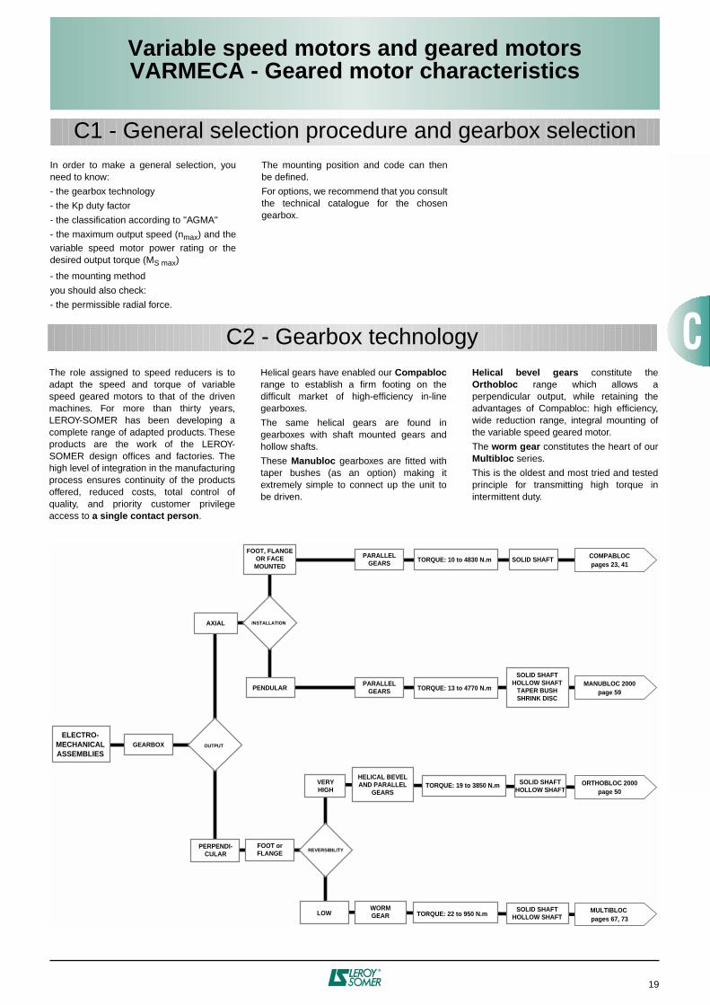
In order to make a general selection, youneed to know:
- the gearbox technology
- the Kp duty factor
- the classification according to "AGMA"
- the maximum output speed (
n
max
) and thevariable speed motor power rating or thedesired output torque (M
S max
)
- the mounting method
you should also check:
- the permissible radial force.
The mounting position and code can thenbe defined.
For options, we recommend that you consultthe technical catalogue for the chosengearbox.
C1 - General selection procedure and gearbox selection
C2 - Gearbox technology
ELECTRO-MECHANICALASSEMBLIES
PERPENDI-CULAR
PARALLELGEARS
PARALLELGEARS
WORMGEAR
SOLID SHAFTTORQUE: 10 to 4830 N.m
TORQUE: 13 to 4770 N.m
TORQUE: 19 to 3850 N.m
TORQUE: 22 to 950 N.m
COMPABLOCpages 23, 41
MANUBLOC 2000page 59
ORTHOBLOC 2000page 50
MULTIBLOC pages 67, 73
FOOT, FLANGEOR FACEMOUNTED
FOOT orFLANGE
LOW
SOLID SHAFTHOLLOW SHAFT
TAPER BUSHSHRINK DISC
HELICAL BEVELAND PARALLEL
GEARS
SOLID SHAFTHOLLOW SHAFT
VERYHIGH
SOLID SHAFTHOLLOW SHAFT
OUTPUT
REVERSIBILITY
INSTALLATIONAXIAL
PENDULAR
GEARBOX
The role assigned to speed reducers is toadapt the speed and torque of variablespeed geared motors to that of the drivenmachines. For more than thirty years,LEROY-SOMER has been developing acomplete range of adapted products. Theseproducts are the work of the LEROY-SOMER design offices and factories. Thehigh level of integration in the manufacturingprocess ensures continuity of the productsoffered, reduced costs, total control ofquality, and priority customer privilegeaccess to
a single contact person
.
Helical gears have enabled our
Compabloc
range to establish a firm footing on thedifficult market of high-efficiency in-linegearboxes.
The same helical gears are found ingearboxes with shaft mounted gears andhollow shafts.
These
Manubloc
gearboxes are fitted withtaper bushes (as an option) making itextremely simple to connect up the unit tobe driven.
Helical bevel gears
constitute the
Orthobloc
range which allows aperpendicular output, while retaining theadvantages of Compabloc: high efficiency,wide reduction range, integral mounting ofthe variable speed geared motor.
The
worm gear
constitutes the heart of our
Multibloc
series.
This is the oldest and most tried and testedprinciple for transmitting high torque inintermittent duty.

20
Variable speed motors and geared motorsVARMECA - Geared motor characteristics
C3 - Selection for gearboxes
* : either version A or B
* : either version A or B
* : either version A or B
Rated output power
Rated torque 320 to 2250
min
–1
Rated motor current Starting torque/Rated
torqueno brake
Moment of inertiawith
FMC brakewith
FCR J01 brake
Braking torque FMC FCR J0 brake brake
Motor type
VARMECA type
P
N
kW
M
N
N.m
I
N
(230 V)
A
M
D
/M
N
J
J 10
–3
kg.m
2
Mf ± 20 %
N.m
LS 71
VMA* 21 M 025 0.25 1.1 1.22 2.2 0.675 0.71 1.07 2.5 2.5
LS 71
VMA* 21 M 037 0.37 1.6 1.95 3 0.85 0.88 1.25 2.5 4
LS 71
VMA* 21 M 055 0.55 2.35 2.9 3 1.1 - 1.5 - 4
LS 80 L
VMA* 21 M 075 0.75 3.2 3.5 3 1.8 - 2.8 - 6
LS 80 L
VMA* 22 M 090 0.9 3.8 4 2.9 2.4 - 3.4 - 6
LS 90 L
VMA* 22 M 110 1.1 4.7 4.7 2.7 3.2 - 5 - 10
LS 90 L
VMA* 22 M 150 1.5 6.4 6.1 2.8 3.9 - 5.7 - 10
Rated output power
Rated torque 320 to 2250
min
–1
Rated motor current Starting torque/Rated
torqueno brake
Moment of inertiawith
FMC brakewith
FCR J01 brake
Braking torque FMC FCR J0 brake brake
Motor type
VARMECA type
P
N
kW
M
N
N.m
I
N
(230 V)
A
M
D
/M
N
J
J 10
–3
kg.m
2
Mf ± 20 %
N.m
LS 71
VMA* 21 TL 025 0.25 1.1 1.22 2.2 0.67 0.71 1.07 2.5 2.5
LS 71
VMA* 21 TL 037 0.37 1.6 1.95 3 0.85 0.88 1.25 2.5 4
LS 71
VMA* 21 TL 055 0.55 2.35 2.9 3 1.1 - 1.5 - 4
LS 80 L
VMA* 21 TL 075 0.75 3.2 3.5 3 1.8 - 2.8 - 6
LS 80 L
VMA* 22 TL 090 0.9 3.8 4 2.9 2.4 - 3.4 - 6
LS 90 L
VMA* 22 TL 110 1.1 4.7 4.7 2.7 3.2 - 5 - 10
LS 90 L
VMA* 22 TL 150 1.5 6.4 6.1 2.8 3.9 - 5.7 - 10
LS 90 L
VMA* 22 TL 180 1.8 7.7 7.1 3 4.9 - 6.7 - 15
LS 100 L
VMA* 22 TL 220 2.2 9.4 8.85 2.7 5.6 - 7.4 - 15
Rated output power
Rated torque 320 to 2250
min
–1
Rated motor current Starting torque/Rated
torqueno brake
Moment of inertiawith
FMC brakewith
FCR J01 brake
Braking torque FMC FCR J0 brake brake
Motor type
VARMECA type
P
N
kW
M
N
N.m
I
N
(400 V)
A
M
D
/M
N
J
J 10
–3
kg.m
2
Mf ± 20 %
N.m
LS 71
VMA* 21 T 025 0.25 1.1 0.7 2.9 0.67 0.71 1.07 2.5 2.5
LS 71
VMA* 21 T 037 0.37 1.6 1.12 3 0.85 0.88 1.25 2.5 4
LS 71
VMA* 21 T 055 0.55 2.35 1.65 3 1.1 - 1.5 - 4
LS 80 L
VMA* 21 T 075 0.75 3.2 2 3 1.8 - 2.8 - 6
LS 80 L
VMA* 21 T 090 0.9 3.8 2.3 2.9 2.4 - 3.4 - 6
LS 90 L
VMA* 21 T 110 1.1 4.7 2.7 2.7 3.2 - 5 - 10
LS 90 L
VMA* 22 T 150 1.5 6.4 3.5 2.8 3.9 - 5.7 - 10
LS 90 L
VMA* 22 T 180 1.8 7.7 4.1 3 4.9 - 6.7 - 15
LS 100 L
VMA* 22 T 220 2.2 9.4 5.1 2.7 5.6 - 7.4 - 15
LS 100 L
VMA* 22 T 300 3 12.8 7.2 2.3 6.5 - 8.3 - 15
LS 112 MG
VMA* 22 T 400 4 17 8 2.3 15 - 19.3 - 22
LS 132 SM
VMA 14.550 5.5 23.4 11 2 33 - - - -
LS 132 M
VMA 14.750 7.5 31.9 14 1.5 35 - - - -
SINGLE-PHASE POWER SUPPLY: 200 V -10 % to 240 V +10% - 50/60 Hz ± 10%3-phase motors 230 V / 400 V ±10 %
∆
CONNECTED - 4 poles
3-PHASE POWER SUPPLY: 200 V -10 % to 240 V +10% - 50/60 Hz ± 10%3-phase motors 230 V / 400 V
∆
CONNECTED - 4 poles
4poles
3-PHASE POWER SUPPLY: VMA 21 and 22, 400 V -10% to 480 V +10% - 50/60 Hz ± 10% VMA 14, 400 V -10% to 440 V +10% - 50/60 Hz ± 10%
3-phase motors 230 V / 400 V ±10%
Υ
CONNECTED - 4 poles4
poles
4poles

21
Variable speed motors and geared motorsVARMECA - Geared motor characteristics
Key
M
N
: rated motor torque in S1 duty
M
D
: starting torque
M
max
: maximum overload torque
N min
-1
: motor speed of rotation
Constant torque for range of speed from 1 to 7
C4 - Torque/speed characteristics

22
Variable speed motors and geared motorsVARMECA - Geared motor characteristics

23
Variable speed geared motorsVARMECA + COMPABLOC 3000Variable speed geared motors
VARMECA + COMPABLOC 3000
D1 - General
Component Materials Remarks
Frame Aluminium (30)Cast iron (31 to 33)
- use of cast aluminium- use of ENGJL-200 cast iron (flake graphite: 200 MPa tensile strength) singlecomponent perlite to ensure unit is fully sealed- monobloc ribbed with internal reinforcements to absorb vibrations and noise, andincrease its rigidity- foot mounted
S
, form
BT
or with flanges
BS
,
BD
. They are compact and meetindustrial requirements
Gears Steel Ni Cr Mo - cut by the gear hob, they are heat treated and then undergo final machining. Thequality and precision of the gear cutting allow maximum torque with minimum noiselevel
Shaft Steel - grinding of sealing surfaces- key in accordance with ISO R773- tolerance of diameters in accordance with NF E 22-051 and ISO R775- tapped holes at the shaft end for fixing connecting devices in accordance with DIN332 version D
Lipseals Nitrile - sealing ring on motor side- sealed gasket with antidust lipseal in accordance with DIN 3760 form AS- gasket under the access cover
Lubrication Oil - in accordance with ISO 6743/6- delivered with the quantity of oil corresponding to the operating position, it is fittedwith drain, level and breather plugs (except Cb 30)
Mounting MI: geared motor with integral mountingMU: geared motor with IEC motor, manufactured with universal mounting
VARMECAvariable speed motor
VARMECA: single-phase power supply 200/240 V, 3-phase 200 V to 480 VLS motor: - 3-phase 230/400 V- pressed steel fan cover, on request fitted with a drip cover for operation in verticalposition (shaft facing down)- VARMECA casing in aluminium with cable gland supplied- VARMECA protection IP 65- motor protection IP 55, class F
VARMECA variable speed motor and brake
FMC: failsafe brake, from 0.25 to 0.37 kW, IP 44 protection (LS 71)FCR: failsafe brake, from 0.25 to 4 kW, IP 55 protection (LS 71 to 112)
Finish Paint Shade: RAL 6000 (green), system
I
(1 polyurethane vinyl layer of 25/30 µm)
D2 - Construction
Compabloc 3000 speed reducers withparallel gears are used to adapt the speed ofthe electric motor to that of the drivenmachine.Their size is therefore determined by themotor power (
P
) expressed in kilowatts (kW)and the output rotation speeds of thegearbox (n
min
-n
max
) in revolutions per minute(min
–1
).
The main characteristic of speed reducers isthe rated output torque (M
nS
) expressed innewton-metres (N.m):
M
nS
=
×
efficiency
A range of four sizes: 30, 31, 32, 33.Rated output torque: from 10 N.m to 1000N.m.Power ratings: from 0.25 to 7.5 kW.Reduction ratios: 1.25 to 200.High efficiency: 95% to 98%.Reversible.Quiet operation.
P
×
9550n
S

24
Variable speed geared motorsVARMECA + COMPABLOC 3000
D3 - Mounting arrangements
Standard position: gearbox view from side F, motor behind, side D on the floor.
1 - Definition of mounting form: S, BS, BDn…, BT
S BS BDn… BT
Foot mounted housing Flange mounted housing Flange mounted housing (different Housing on side F with clearance holes diameter) with clearance holes with tapped holes
B3 B6 B7 B8 V5 V6
V1 V3
M*: For these multi-position geared motors (M), the positions need only be specified if the following are required: vent hole on the gearbox and/or condensate drainholeson the motor. They MUST be specified for positions V3 and V6.
3 - VARMECA positions 4 - Cable gland positions
13
A
C
BD
B5 B52 B53 B54
2 - Definition of operating position
2.1 - S foot mounted
1-stage Compabloc: Cb 3031* and 3131 to 3331, multi-stage Compabloc: Cb 3032* and 3033* - Cb 3133 to 3333
2.2 - With BS, BDn… flange, or BT faceplate
1-stage Compabloc: Cb 3031* and 3131 to 3331, multi-stage Compabloc: Cb 3032* and 3033* - Cb 3133 to 3333
A: Standard VMA 20: 1, standard VMA 14: BD, CG on right or BG, CG on left

25
Solid cylindrical
Feet
various diameters of flangeBS, BDn, etc
Solid extended cylindrical
OUTPUT SHAFT GEARBOX HOUSING DRIVE SYSTEM
“MI” integral VARMECA with or without brake
“MU-FF”universal mounting
B5 IEC standardVARMECA
with or without brake
BT form
Mountingform
Operatingposition
Gearboxtype
Cb
Size andmanufacturer
code
3333 B3 S
Input type
MI
Exactreduction
57.6
No. ofpoles
4P
Series, frame size
and manufacturer code
LS 90L
Rated powerin kW
1.8 kW
VARMECArating
VMA 22T 180
VARMECA,CG
position
A1
Option
BMA
Selection example:Required power: 1.8 kW - 3-ph 400 VRequired speeds: 6 to 40 min–1
Duty factor necessary for the application: kp = 2Mounting: foot, horizontal positionCG position: cable gland on rightDesignation: Cb 3333 B3 S 57.6 MI - 4P LS 90 L 1.8 kW - VMA 22T 180
Variable speed geared motorsVARMECA + COMPABLOC 3000
D4 - Adaptation possibilities
D5 - Designation / Coding
Leroy-Somer offers several adaptations for its gearboxes which respond to very wide-rangingneeds. They are described below and offered in the Leroy-Somer configurator.For other drives, consult the Leroy-Somer technical specialists who will be glad to assist.

26
Variable speed geared motorsVARMECA + COMPABLOC 3000
D6 - Selection (kp factor for AGMA class
I
,
II
,
III
)
Compabloc 3031 (Cb) gearbox
:
S
foot mounted form,
BT
faceplate,
BS, BDn...
flange form
VARMECA variable speed motors
: LS 4-pole, IP 65, class F- 3-phase
T
: 400 V -10% to 480 V +10%, 50-60 Hz ±10%- 3-phase
TL
: 200 V -10% to 240 V +10%, 50-60 Hz ±10%- Single-phase
M
: 200 V -10% to 240 V +10%, 50-60 Hz ±10%
Variable speed brake motors
: 4-pole, class F
FCR J01
: IP 55, from 0.25 to 0.9 kW
FMC
: IP 44, from 0.25 to 0.37 kW
Integral mounting
MI
Universal mounting
MU-FF
Maximumoutputspeedmin–1
277312352387435491552621695818882102711501232146315391704
Minimumoutputspeedmin–1
39.444.35055
61.969.878.588.398.9116126146164175208219242
Exactreduction
8.137.226.45.825.174.584.083.633.242.752.552.191.961.831.541.461.32
2.082.342.642.903.273.694.154.665.226.156.637.728.649.2610.9911.5612.83
1.361.531.731.902.142.412.713.053.424.024.345.055.666.067.197.578.40
1.591.792.012.252.652.863.333.733.994.744.995.54
1.151.301.461.631.922.072.412.702.903.443.624.02
1.081.211.351.591.722.002.242.402.853.003.33
21T025 21T037 21T055 21T075 21T090 21T110 22T150 22T180 22T220 22T300 22T400 14-550 14-750
21TL025 21TL037 21TL055 21TL075 22TL090 22TL110 22TL150 22TL180 22TL220 NA NA NA NA
21M025 21M037 21M055 21M075 22M090 22M110 22M150 NA NA NA NA NA NA
NA NA3-phase 4-pole LS brake motor and frame size
3-phase VMA -- T --- 400/480 V
3-phase VMA -- TL --- 200/240 V
Single phase VMA -- M --- 200/240 V
71 L 80 L 90 L 100 L 112 MG 132 SM 132 M
VARMECA variable speed motors, power kW
3-phase 4-pole LS motor and frame size0.25 0.37 0.55 0.75 0.9 1.1 1.5 1.8 2.2
71 FMC ou 71 L FCR 80 L FCR71 L FCR 90 L FCR 100 L FCR 112MG FCR
3 4 7.55.5
Cb 3031 from 277 to 1704 min–1
not availableNA
Selection example:
Required power: 0.75 kW - 3-ph 400 VRequired speeds: 69.8 to 491 min
–1
Duty factor necessary for the application: kp = 1Mounting: foot, horizontal positionCG position: cable gland on right
Designation: Cb 3031 M S
4.58 MI - 4P LS 80 L 0.75 kW - VMA 21T 075

27
Variable speed geared motorsVARMECA + COMPABLOC 3000
D6 - Selection (kp factor for AGMA class
I
,
II
,
III
)
Compabloc 3032 and Cb 3033 (Cb) gearbox
:
S
foot mounted form,
BT
faceplate,
BS, BDn...
flange form
VARMECA variable speed motors
: LS 4-pole, IP 65, class F- 3-phase
T
: 400 V -10% to 480 V +10%, 50-60 Hz ±10%- 3-phase
TL
: 200 V -10% to 240 V +10%, 50-60 Hz ±10%- Single-phase
M
: 200 V -10% to 240 V +10%, 50-60 Hz ±10%
Variable speed brake motors
: 4-pole, class F
FCR J01
: IP 55, from 0.25 to 0.9 kW
FMC
: IP 44, from 0.25 to 0.37 kW
Integral mounting
MI
Universal mounting
MU-FF
Maximumoutputspeedmin–1
19.522
24.727.732.635.141
45.849
58.261.3
49.655.863
69.378
87.998.9111125147158184206221262276305
Minimumoutputspeedmin–1
2.783.123.513.944.634.995.816.516.978.288.71
7.057.948.969.8511.112.514.115.817.720.822.526.229.331.437.339.243.4
Exactreduction
11510291.181.369.164.155
49.245.938.736.7
45.440.335.732.528.825.622.820.218.115.414.212.210.910.28.598.167.38
1.011.131.331.431.651.841.972.322.44
2.112.372.662.923.283.694.144.645.186.076.537.568.43
1.081.211.291.521.60
1.381.551.741.912.152.422.713.043.393.974.274.955.525.906.967.318.08
1.001.05
1.591.782.002.232.622.823.263.643.894.584.815.32
1.151.291.451.621.902.042.362.642.823.323.493.86
1.071.201.341.571.691.962.192.342.762.893.20
21T025 21T037 21T055 21T075 21T090 21T110 22T150 22T180 22T220 22T300 22T400 14-550 14-750
21TL025 21TL037 21TL055 21TL075 22TL090 22TL110 22TL150 22TL180 22TL220 NA NA NA NA
21M025 21M037 21M055 21M075 22M090 22M110 22M150 NA NA NA NA NA NA
NA NA3-phase 4-pole LS brake motor and frame size
3-phase VMA -- T --- 400/480 V
3-phase VMA -- TL --- 200/240 V
Single phase VMA -- M --- 200/240 V
71 L 80 L 90 L 100 L 112 MG 132 SM 132 M
VARMECA variable speed motors, power kW
3-phase 4-pole LS motor and frame size0.25 0.37 0.55 0.75 0.9 1.1 1.5 1.8 2.2
71 L FCR71 FMC ou 71 L FCR 80 L FCR 90 L FCR 100 L FCR 112MG FCR
3 4 7.55.5
Cb 3032 and Cb 3033 from 19.5 to 305 min–1
Cb 3033
Cb 3032
not availableNA
Selection example:
Required power: 0.55 kW - 3-ph 400 VRequired speeds: 9 to 63 min
–1
Duty factor necessary for the application: kp = 1Mounting: foot, vertical position, shaft facing upCG position: cable gland on right
Designation: Cb 3032 V6 S
35.7 MI - 4P LS 71 L 0.55 kW - VMA 21T 055

28
Variable speed geared motorsVARMECA + COMPABLOC 3000
D6 - Selection (kp factor for AGMA class
I
,
II
,
III
)
Compabloc 3131 (Cb) gearbox
:
S
foot mounted form,
BT
faceplate,
BS, BDn...
flange form
VARMECA variable speed motors
: LS 4-pole, IP 65, class F- 3-phase
T
: 400 V -10% to 480 V +10%, 50-60 Hz ±10%- 3-phase
TL
: 200 V -10% to 240 V +10%, 50-60 Hz ±10%- Single-phase
M
: 200 V -10% to 240 V +10%, 50-60 Hz ±10%
Variable speed brake motors
: 4-pole, class F
FCR J01
: IP 55, from 0.25 to 3 kW
Integral mounting
MI
Universal mounting
MU-FF
Maximumoutputspeedmin–1
28431436039545851357365569282287298411251278144616311846
Minimumoutputspeedmin–1
40.544.751.256.265.173
81.593.198.5117124140160182206232263
Exactreduction
7.917.176.255.694.924.383.933.443.252.742.582.29
21.761.561.381.22
6.867.578.679.5211.0312.3713.8015.7716.6819.7120.2421.6422.76
4.454.915.636.187.158.028.9510.2310.8212.7913.1414.0414.7715.45
3.694.054.695.265.876.707.098.388.609.209.6710.12
11.68
2.672.933.393.804.244.855.136.066.226.656.997.31
8.45
2.212.422.803.153.514.014.245.015.155.505.796.05
6.99
2.282.562.863.263.454.084.194.484.714.925.125.315.69
1.661.862.082.382.512.973.053.263.433.593.733.874.14
1.381.551.731.972.092.472.532.712.852.983.103.213.44
1.131.261.411.611.702.012.072.212.322.432.532.622.81
1.031.181.241.471.511.611.701.781.851.912.05
21T025 21T037 21T055 21T075 21T090 21T110 22T150 22T180 22T220 22T300 22T400 14-550 14-750
21TL025 21TL037 21TL055 21TL075 22TL090 22TL110 22TL150 22TL180 22TL220 NA NA NA NA
21M025 21M037 21M055 21M075 22M090 22M110 22M150 NA NA NA NA NA NA
NA NA3-phase 4-pole LS FCR J01 brake motor and frame size
3-phase VMA -- T --- 400/480 V
3-phase VMA -- TL --- 200/240 V
Single phase VMA -- M --- 200/240 V
71 L 80 L 90 L 100 L 112 MG 132 SM 132 M
VARMECA variable speed motors, power kW
3-phase 4-pole LS motor and frame size0.25 0.37 0.55 0.75 0.9 1.1 1.5 1.8 2.2
71 L FCR 80 L FCR 90 L FCR 100 L FCR 112MG FCR
3 4 7.55.5
Cb 3131 from 284 to 1846 min–1
not availableNA
Selection example:
Required power: 1.8 kW - 3-ph 400 VRequired speeds: 65 to 458 min
–1
Duty factor necessary for the application: kp = 1Mounting: foot, horizontal positionCG position: cable gland on right
Designation: Cb 3131 B3 S
4.92 MI - 4P LS 90 L 1.8 kW - VMA 22T 180

29
Variable speed geared motorsVARMECA + COMPABLOC 3000
D6 - Selection (kp factor for AGMA class
I
,
II
,
III
)
Compabloc 3133 (Cb) gearbox
:
S foot mounted form, BT faceplate, BS, BDn... flange form VARMECA variable speed motors: LS 4-pole, IP 65, class F
- 3-phase T: 400 V -10% to 480 V +10%, 50-60 Hz ±10%- 3-phase TL: 200 V -10% to 240 V +10%, 50-60 Hz ±10%- Single-phase M: 200 V -10% to 240 V +10%, 50-60 Hz ±10%
Variable speed brake motors: 4-pole, class F FCR J01: IP 55, from 0.25 to 3 kW
Integral mounting MI
Universal mounting MU-FF
Maximumoutputspeedmin–1
11.212.414.215.618
20.322.625.927.432.534.538.944.545.850.557.963.673.682.692.2105111132140158181206216233256263272297307350398451508575
Minimumoutputspeedmin–1
1.571.762.022.222.572.883.223.683.894.624.95.536.326.517.198.249.0510.411.713.115
15.818.820
22.525.629.330.733.136.437.338.742.343.649.856.664.172.381.8
Exactreduction
20018115814412411199.487
82.269.265.357.850.649.144.538.835.430.627.224.421.420.21716
14.212.410.910.49.678.798.578.287.577.346.425.654.994.433.91
1.121.231.391.481.631.761.902.072.152.412.512.72
4.514.975.686.227.188.028.93
1.061.141.231.351.401.571.631.77
2.933.223.684.044.665.215.796.546.897.898.23
9.64
11.44
12.06
1.031.071.161.26
2.412.643.053.413.794.284.515.175.395.846.396.966.31
7.49
8.859.6310.02
1.741.912.202.462.743.103.263.743.894.224.625.034.56
5.42
6.406.406.967.25
8.64
1.441.581.832.042.272.562.703.093.223.503.824.173.78
4.49
5.305.305.776.00
7.15
1.852.092.202.522.622.843.113.39
3.68
3.98
4.314.314.694.885.075.225.82
1.341.521.601.831.912.072.272.47
2.68
2.90
3.143.143.423.553.693.804.24
1.121.261.331.521.591.721.882.05
2.23
2.41
2.612.612.842.953.073.163.52
1.031.081.241.291.401.531.67
1.82
1.97
2.132.132.312.412.502.582.87
1.031.121.22
1.33
1.44
1.551.551.691.761.831.882.10
21T025 21T037 21T055 21T075 21T090 21T110 22T150 22T180 22T220 22T300 22T400 14-550 14-750
21TL025 21TL037 21TL055 21TL075 22TL090 22TL110 22TL150 22TL180 22TL220 NA NA NA NA
21M025 21M037 21M055 21M075 22M090 22M110 22M150 NA NA NA NA NA NA
NA NA3-phase 4-pole LS FCR J01 brake motor and frame size
3-phase VMA -- T --- 400/480 V
3-phase VMA -- TL --- 200/240 V
Single phase VMA -- M --- 200/240 V
71 L 80 L 90 L 100 L 112 MG 132 SM 132 M
VARMECA variable speed motors, power kW
3-phase 4-pole LS motor and frame size0.25 0.37 0.55 0.75 0.9 1.1 1.5 1.8 2.2
71 L FCR 80 L FCR 90 L FCR 100 L FCR 112MG FCR
3 4 7.55.5
Cb 3133 from 11.2 to 575 min–1
not availableNA
Selection example:Required power: 1.5 kW - 3-ph 400 VRequired speeds: 16 to 110 min–1
Duty factor necessary for the application: kp = 1.4Mounting: foot, horizontal positionCG position: cable gland on right, button optionDesignation: Cb 3133 B3 S 20.2 MI - 4P LS 90 L 1.5 kW - VMA 22T 150+BMA

30
Variable speed geared motorsVARMECA + COMPABLOC 3000
D6 - Selection (kp factor for AGMA class I, II, III)
Compabloc 3231 (Cb) gearbox: S foot mounted form, BT faceplate, BS, BDn... flange form VARMECA variable speed motors: LS 4-pole, IP 65, class F
- 3-phase T: 400 V -10% to 480 V +10%, 50-60 Hz ±10%- 3-phase TL: 200 V -10% to 240 V +10%, 50-60 Hz ±10%- Single-phase M: 200 V -10% to 240 V +10%, 50-60 Hz ±10%
Variable speed brake motors: 4-pole, class F FCR J01: IP 55, from 0.25 to 4 kW
Integral mounting MI
Universal mounting MU-FF
Maximumoutputspeedmin–1
279325357394462519578656729827884101911611286145315501831
Minimumoutputspeedmin–1
39.646.350.756
65.673.982.293.3104118126145165183207220260
Exactreduction
8.086.926.315.714.884.333.893.433.092.722.552.211.941.751.551.451.23
10.8612.6813.9015.3417.9920.2322.5125.5728.40
7.028.198.999.9211.6313.0814.5516.5318.3620.8422.2725.24
4.595.355.876.487.608.559.5110.8012.0013.6214.5516.4917.94
3.313.874.244.685.486.176.877.808.669.8310.5011.9112.95
2.743.203.513.874.545.115.686.457.178.138.699.8510.72
2.602.853.153.694.154.625.255.836.617.078.018.71
1.892.082.292.693.023.363.824.244.815.145.836.34
1.571.721.902.232.512.793.173.524.004.274.845.26
1.281.411.551.822.052.282.592.873.263.483.954.29
1.131.331.491.661.892.102.382.542.883.143.183.433.333.60
0.991.121.241.411.571.781.902.162.352.382.562.492.70
21T025 21T037 21T055 21T075 21T090 21T110 22T150 22T180 22T220 22T300 22T400 14-550 14-750
21TL025 21TL037 21TL055 21TL075 22TL090 22TL110 22TL150 22TL180 22TL220 NA NA NA NA
21M025 21M037 21M055 21M075 22M090 22M110 22M150 NA NA NA NA NA NA
NA NA3-phase 4-pole LS FCR J01 brake motor and frame size
3-phase VMA -- T --- 400/480 V
3-phase VMA -- TL --- 200/240 V
Single phase VMA -- M --- 200/240 V
71 L 80 L 90 L 100 L 112 MG 132 SM 132 M
VARMECA variable speed motors, power kW
3-phase 4-pole LS motor and frame size0.25 0.37 0.55 0.75 0.9 1.1 1.5 1.8 2.2
71 L FCR 80 L FCR 90 L FCR 100 L FCR 112MG FCR
3 4 7.55.5
Cb 3231 from 279 to 1831 min–1
not availableNA
Selection example:Required power: 3 kW - 3-ph 400 VRequired speeds: 56 to 394 min–1
Duty factor necessary for the application: kp = 1Mounting: foot, horizontal positionCG position: cable gland on rightDesignation: Cb 3231 B3 S 5.71 MI - 4P LS 100 L 3 kW - VMA 22T 300

31
Variable speed geared motorsVARMECA + COMPABLOC 3000
D6 - Selection (kp factor for AGMA class I, II, III)
Selection example:Required power: 2.2 kW - 3-ph 400 VRequired speeds: 7.5 to 52 min–1
Duty factor necessary for the application: kp = 1Mounting: foot, horizontal positionCG position: cable gland on rightDesignation: Cb 3233 B3 S 43 MI - 4P LS 100 L 2.2 kW - VMA 22T 220
Maximumoutputspeedmin–1
1112.914.115.618.320.622.926
28.932.835
40.444.846
52.457.463.474.383.693106117133142164183187207208231234249263281295323369408461492581
Minimumoutputspeedmin–1
1.571.832.012.222.62.933.263.74.114.664.985.756.386.557.448.169.0110.611.913.215
16.718.920.223.326
26.629.429.632.933.335.537.439.941.946
52.458
65.670
82.7
Exactreduction
20417415914412310998.286.577.968.664.255.750.248.943
39.235.530.326.924.221.319.216.915.813.712.312
10.910.89.729.629.028.578.027.636.966.15.514.884.573.87
2.512.933.213.544.154.675.205.906.557.437.939.119.98
11.6112.7113.99
1.621.892.072.292.683.023.363.814.244.805.125.896.45
7.518.219.0410.4611.6512.57
14.56
1.061.241.361.501.751.972.202.492.773.143.353.854.22
4.915.375.916.847.618.228.969.6110.4710.94
10.8012.00
13.6214.55
1.271.421.581.802.002.272.422.783.04
3.543.874.274.945.495.936.476.947.567.908.70
9.47
7.808.66
9.8310.51
12.1113.80
1.051.181.311.491.651.872.002.302.52
2.933.213.534.084.554.915.355.746.266.547.20
7.84
6.457.17
8.148.69
10.0211.42
1.631.87
2.122.382.612.873.323.703.994.354.675.095.315.85
6.37
5.255.83
6.617.07
8.159.29
1.181.36
1.551.731.902.092.422.692.903.173.403.703.874.26
4.64
3.824.24
4.815.14
5.936.76
0.981.13
1.281.441.581.732.012.232.412.632.823.073.213.54
3.85
3.173.52
4.004.27
4.925.61
1.051.171.281.411.641.821.972.142.302.512.622.88
3.14
2.592.87
3.263.48
4.024.58
1.031.201.331.441.571.681.831.912.11
2.292.46
2.662.78
3.092.933.343.684.124.374.82
1.171.261.371.431.58
1.721.84
1.992.08
2.312.192.502.763.083.273.60
21T025 21T037 21T055 21T075 21T090 21T110 22T150 22T180 22T220 22T300 22T400 14-550 14-750
21TL025 21TL037 21TL055 21TL075 22TL090 22TL110 22TL150 22TL180 22TL220 NA NA NA NA
21M025 21M037 21M055 21M075 22M090 22M110 22M150 NA NA NA NA NA NA
NA NA3-phase 4-pole LS FCR J01 brake motor and frame size
3-phase VMA -- T --- 400/480 V
3-phase VMA -- TL --- 200/240 V
Single phase VMA -- M --- 200/240 V
71 L 80 L 90 L 100 L 112 MG 132 SM 132 M
VARMECA variable speed motors, power kW
3-phase 4-pole LS motor and frame size0.25 0.37 0.55 0.75 0.9 1.1 1.5 1.8 2.2
71 L FCR 80 L FCR 90 L FCR 100 L FCR 112MG FCR
3 4 7.55.5
Cb 3233 from 11 to 581 minÐ1
not availableNA
Compabloc 3233 (Cb) gearbox: S foot mounted form, BT faceplate, BS, BDn... flange form VARMECA variable speed motors: LS 4-pole, IP 65, class F
- 3-phase T: 400 V -10% to 480 V +10%, 50-60 Hz ±10%- 3-phase TL: 200 V -10% to 240 V +10%, 50-60 Hz ±10%- Single-phase M: 200 V -10% to 240 V +10%, 50-60 Hz ±10%
Variable speed brake motors: 4-pole, class F FCR J01: IP 55, from 0.25 to 4 kW
Integral mounting MI
Universal mounting MU-FF

32
Variable speed geared motorsVARMECA + COMPABLOC 3000
D6 - Selection (kp factor for AGMA class I, II, III)
Compabloc 3331 (Cb) gearbox: S foot mounted form, BT faceplate, BS, BDn... flange form VARMECA variable speed motors: LS 4-pole, IP 65, class F
- 3-phase: • VMA 21 and 22 T: 400 V -10% to 480 V +10%, 50-60 Hz ±10% • VMA 14: 400 V -10% to 440 V +10%, 50-60 Hz ±10%- 3-phase TL: 200 V -10% to 240 V +10%, 50-60 Hz ±10%- Single-phase M: 200 V -10% to 240 V +10%, 50-60 Hz ±10%
Variable speed brake motors: 4-pole, class F FCR J01: IP 55, from 0.25 to 4 kW
Integral mounting MI
Universal mounting MU-FF
Maximumoutputspeedmin–1
287318355409462503569639712773871100011051268140115441781
Minimumoutputspeedmin–1
40.945.250.558.265.871.581
90.9101110124142157180199220253
Exactreduction
7.837.086.335.54.874.473.953.523.162.912.582.252.041.771.611.461.26
21.4523.7426.53> 30> 30> 30> 30
13.7615.2317.0219.5721.9122.9125.1626.1326.97> 30> 30
8.959.9011.0612.7314.2414.8916.3616.9917.5420.8224.2323.66
6.447.137.979.1710.2610.7311.7812.2412.6314.9917.4517.04
5.325.896.597.588.488.879.7410.1110.4412.3914.4214.08
4.324.795.356.156.897.207.918.218.4810.0611.7111.44
3.143.483.894.475.015.235.755.976.167.328.528.31
2.612.893.233.714.154.344.774.965.116.077.076.90
2.132.352.633.033.393.543.894.044.174.955.765.63
1.922.212.472.592.842.953.043.614.214.114.324.07
4.14
1.441.651.851.932.122.212.282.703.153.073.233.05
3.09
1.341.401.541.601.651.962.282.232.342.212.212.242.36
0.981.03
1.171.211.441.671.631.721.621.621.641.73
21T025 21T037 21T055 21T075 21T090 21T110 22T150 22T180 22T220 22T300 22T400 14-550 14-750
21TL025 21TL037 21TL055 21TL075 22TL090 22TL110 22TL150 22TL180 22TL220 NA NA NA NA
21M025 21M037 21M055 21M075 22M090 22M110 22M150 NA NA NA NA NA NA
NA NA3-phase 4-pole LS FCR J01 brake motor and frame size
3-phase VMA -- T --- 400/480 V
3-phase VMA -- TL --- 200/240 V
Single phase VMA -- M --- 200/240 V
71 L 80 L 90 L 100 L 112 MG 132 SM 132 M
VARMECA variable speed motors, power kW
3-phase 4-pole LS motor and frame size0.25 0.37 0.55 0.75 0.9 1.1 1.5 1.8 2.2
71 L FCR 80 L FCR 90 L FCR 100 L FCR 112MG FCR
3 4 7.55.5
Cb 3331 from 287 to 1781 min–1
not availableNA
Selection example:Required power: 5.5 kW - 3-ph 400 VRequired speeds: 58 to 409 min–1
Duty factor necessary for the application: kp = 1Mounting: foot, horizontal positionCG position: cable gland on rightDesignation: Cb 3331 B3 S 5.5 MI - 4P LS 132 SM 5.5 kW - 14-550

33
Variable speed geared motorsVARMECA + COMPABLOC 3000
D6 - Selection (kp factor for AGMA class I, II, III)
Maximumoutputspeedmin–1
11.212.413.916
18.119.722.225
27.830.234
39.146.251.257.265.874.480.991.6103115125140161178181203204225226246249277287318351403445490566
Minimumoutputspeedmin–1
1.61.771.972.272.572.83.163.553.964.34.845.566.577.288.139.3610.611.513
14.616.317.719.922.925.325.728.92932
32.234.935.339.340.845.249.957.363.369.780.4
Exactreduction
20018116214112511410190.180.974.466.157.648.744
39.434.230.227.824.621.919.618.116.114
12.712.511.111
9.989.959.169.068.147.857.096.415.595.064.593.98
4.765.275.896.787.678.349.4410.5911.8012.8114.40
18.7420.74
3.063.383.784.354.925.356.056.797.578.229.24
12.0213.3014.8617.1219.34
1.992.202.462.833.203.483.944.424.925.346.016.887.818.659.6611.1312.5813.6815.4417.18
15.4917.38
1.431.581.772.042.302.502.843.183.543.854.334.955.636.236.968.019.069.8511.1212.3713.5614.5115.82
11.1512.52
13.9515.15
17.06
1.181.311.461.681.902.072.342.632.933.183.584.094.655.155.756.627.498.149.1910.2311.2112.0013.0814.56
9.2210.35
11.5312.52
14.10
16.19
1.681.902.142.382.582.903.323.784.184.675.386.086.617.468.319.109.7410.6211.83
7.498.40
9.3610.17
11.45
13.15
1.221.381.551.731.882.112.422.753.043.403.914.424.815.436.046.627.087.728.60
5.446.11
6.817.39
8.33
9.56
1.011.151.291.441.561.752.012.282.522.823.253.673.994.505.015.495.886.417.14
4.525.07
5.656.14
6.91
7.93
1.051.171.271.431.631.862.062.302.652.993.253.674.084.484.795.225.82
3.684.13
4.615.00
5.63
6.47
1.041.19
1.681.932.182.382.682.983.273.503.814.254.65
4.99
3.36
5.824.11
4.725.225.99
7.29
1.251.441.631.782.002.232.442.622.853.183.48
3.73
2.51
4.353.08
3.533.904.48
5.45
1.181.291.451.621.771.902.072.302.52
2.702.96
3.16
3.462.562.833.253.593.964.56
1.181.301.391.511.691.85
1.982.16
2.31
2.531.882.072.382.632.903.34
21T025 21T037 21T055 21T075 21T090 21T110 22T150 22T180 22T220 22T300 22T400 14-550 14-750
21TL025 21TL037 21TL055 21TL075 22TL090 22TL110 22TL150 22TL180 22TL220 NA NA NA NA
21M025 21M037 21M055 21M075 22M090 22M110 22M150 NA NA NA NA NA NA
NA NA3-phase 4-pole LS FCR J01 brake motor and frame size
3-phase VMA -- T --- 400/480 V
3-phase VMA -- TL --- 200/240 V
Single phase VMA -- M --- 200/240 V
71 L 80 L 90 L 100 L 112 MG 132 SM 132 M
VARMECA variable speed motors, power kW
3-phase 4-pole LS motor and frame size0.25 0.37 0.55 0.75 0.9 1.1 1.5 1.8 2.2
71 L FCR 80 L FCR 90 L FCR 100 L FCR 112MG FCR
3 4 7.55.5
Cb 3333 from 11.2 to 566 minÐ1
not availableNA
See
VARM
ECA + C
b 2000
offer, p
44
Compabloc 3333 (Cb) gearbox: S foot mounted form, BT faceplate, BS, BDn... flange form VARMECA variable speed motors: LS 4-pole, IP 65, class F
- 3-phase: • VMA 21 and 22 T: 400 V -10% to 480 V +10%, 50-60 Hz ±10% • VMA 14: 400 V -10% to 440 V +10%, 50-60 Hz ±10%- 3-phase TL: 200 V -10% to 240 V +10%, 50-60 Hz ±10%- Single-phase M: 200 V -10% to 240 V +10%, 50-60 Hz ±10%
Variable speed brake motors: 4-pole, class F FCR J01: IP 55, from 0.25 to 4 kW
Integral mounting MI
Universal mounting MU-FF
Selection example:Required power: 1.8 kW - 3-ph 400 VRequired speeds: 3 to 22 min–1
Duty factor necessary for the application: kp = 1Mounting: foot, horizontal positionCG position: cable gland on rightDesignation: Cb 3333 B3 S 101 MI - 4P LS 90 L 1.8 kW - VMA 22T 180

34
Variable speed geared motorsVARMECA + COMPABLOC 3000
D7 - Dimensions
OxZ
4 x K
AD
AA
HA
GA
HB
H
HC
A
AB
AA
F
R
RC
E
Bf
C
BB
D
x
EX EY
LBH
Jh
AC
JLJ III
Dimensions of VARMECA + Compabloc (Cb) gearboxes, MI integral mounting, 1 stage,Cb 3031 to Cb 3331
Dimensions in millimetresS foot mounted form
Type
Gearboxes Solid output shaft Max.
A AA AB AD B BB C f H HA HB HC K R RC x D E EX EY F GA O Zweight
kgCb 3331 190 55 240 230 100 145 27.5 22 112 25 185 343 16 136 106 70 35k6 70 5 60 10 38 M12 38 15.5Cb 3231 140 37 180 185 80 115 20.5 17.5 90 20 155 - 14 117 - 63 25j6 50 5 40 8 28 M10 22 8.3Cb 3131 120 35 156 157 75 105 18 15 80 16 122 246 11 113 86 46.5 20j6 40 7 30 6 22.5 M6 16 6.9Cb 3031 125 25 150 140 70 90 21 10 75 13 105 - 9 79 - 35.5 16j6 40 7 25 5 18 M6 16 2.3
Frame size
VARMECA variable speed motorsLS 3-phase LS and FMC brake LS and FCR brake
AC HJmax.
Jmax.LB
min.LJ I II
Max. weight
kg AC HJmax.
Jmax.LB
min.LJ I II
Max. weight
kg AC HJ hmax.
Jmax.LB
min.LJ I II
Max. weight
kg71 140 195 218 240 27 75 75 12.5 140 181 218 279 27 75 75 13.4 140 195 70 218 302 27 75 75 15.280 170 205 231 274 43 75 75 15.1 - - - - - - - - 172 205 80 231 324 43 75 75 22.290 190 215 231 310 73.5 75 75 19.4 - - - - - - - - 184 215 90 231 370 73.5 75 75 28.4100 200 220 231 335 53.5 75 75 26.7 - - - - - - - - 200 220 98 231 398 53.5 75 75 34.2112 235 229 231 459 54 75 75 42.6 - - - - - - - - 235 229 110 231 459 54 75 75 48.7
132 1 280 264 324 438 67 112 112 61 - - - - - - - - - - - - - - - - -
1. In frame size 132, dimension I includes the control button supplied as standard.

35
Variable speed geared motorsVARMECA + COMPABLOC 3000
D7 - Dimensions
Type
Gearboxes BT form Solid output shaft Max.
AB AD BB H HB HC R RC W x M N n S T a D E EX EY F GA O Zweight
kgCb 3331 240 230 135 112 185 343 131 101 15 70 120 100 6 M10x22 3 60° 35k6 70 5 60 10 38 M12 38 15.5Cb 3231 180 185 115 90 155 - 109 - 15 63 83 70 4 M10x22 5 45° 25j6 50 5 40 8 28 M10 22 8.3Cb 3131 156 157 105 80 122 246 106 79 15 46.5 83 70 4 M10x22 5 45° 20j6 40 7 30 6 22.5 M6 16 6.9Cb 3031 - 140 - 57 105 - 67 - 12 35.5 100 60 4 1 18 0° 16j6 40 7 25 5 18 M6 16 2.3
Frame size
VARMECA variable speed motorsLS 3-phase LS and FMC brake LS and FCR brake
AC HJmax.
Jmax.LB
min.LJ I II
Max. weight
kg AC HJmax.
Jmax.LB
min.LJ I II
Max. weight
kg AC HJ hmax.
Jmax.LB
min.LJ I II
Max. weight
kg71 140 195 218 240 27 75 75 12.5 140 181 218 279 27 75 75 13.4 140 195 70 218 302 27 75 75 15.280 170 205 231 274 43 75 75 15.1 - - - - - - - - 172 205 80 231 324 43 75 75 22.290 190 215 231 310 73.5 75 75 19.4 - - - - - - - - 184 215 90 231 370 73.5 75 75 28.4100 200 220 231 335 53.5 75 75 26.7 - - - - - - - - 200 220 98 231 398 53.5 75 75 34.2112 235 229 231 459 54 75 75 42.6 - - - - - - - - 235 229 110 231 459 54 75 75 48.7
132 1 280 264 324 438 67 112 112 61 - - - - - - - - - - - - - - - - -
Dimensions of VARMECA + Compabloc (Cb) gearboxes, MI integral mounting, 1 stage,Cb 3031 to Cb 3331
Dimensions in millimetresBT faceplate form
1. Cb 30 BT with 4 clearance holes Ø 5.65 x 18 for M6 self-tapping screw.
1. In frame size 132, dimension I includes the control button supplied as standard.
OxZ
R
TRC
E W
BB
DN
x
EX EY
H
AD
GA
HB
H
HC
AB
F
n x S / M
a
LBHJ
h
AC
JLJ III
Detail of Cb 30

36
Variable speed geared motorsVARMECA + COMPABLOC 3000
D7 - Dimensions
Dimensions of VARMECA + Compabloc (Cb) gearboxes, MI integral mounting, 1 stage,Cb 3031 to Cb 3331
Dimensions in millimetresBS, BDn flange form
OxZ
R
TRC
E W
BB
DN
x
EX EY
H
AD
GA
HB
H
HC
AB
F
n x S / M
a
LB
HJ
h
AC
JLJ III
Detail of Cb 30
Type
Gearboxes BS form Solid output shaft Max.
AB AD BB H HB HC R RC x LA M N P S T a n D E EX EY F GA O Zweight
kgCb 3331 240 230 145 112 1 85 343 146 116 70 12 215 180 250 14 3.5 45° 4 35k6 70 5 60 10 38 M12 38 19.4Cb 3231 180 185 115 90 155 - 134 - 63 9 165 130 200 11 3.5 45° 4 25j6 50 5 40 8 28 M10 22 10.3Cb 3131 156 157 105 80 122 246 121 94 46.5 10 130 110 160 9 3 45° 4 20j6 40 7 30 6 22.5 M6 16 8.1Cb 3031 - 140 - 90 105 - 79 - 35.5 8 115 95 140 9 3 45° 4 16j6 40 7 25 5 18 M6 16 2.5
Type
Other possible flangesBD1 flange Max. BD2 flange Max. BD3 flange Max.
LA M N P S T a nweight
kg LA M N P S T a nweight
kg LA M N P S T a nweight
kgCb 3331 12 165 130 200 11 3.5 45° 4 18.3 - - - - - - - - - - - - - - - - - -Cb 3231 9 130 110 160 9 3.5 45° 4 9.5 - - - - - - - - - - - - - - - - - -Cb 3131 10 115 95 140 9 3 45° 4 7.9 - - - - - - - - - - - - - - - - - -Cb 3031 10 100 80 120 7 3 45° 4 2.5 10 130 110 160 9 2 45° 4 2.5 12 165 130 200 11 3.5 45° 4 2.5
Frame size
VARMECA variable speed motorsLS 3-phase LS and FMC brake LS and FCR brake
AC HJmax.
Jmax.LB
min.LJ I II
Max. weight
kg AC HJmax.
Jmax.LB
min.LJ I II
Max. weight
kg AC HJ hmax.
Jmax.LB
min.LJ I II
Max. weight
kg71 140 195 218 240 27 75 75 12.5 140 181 218 279 27 75 75 13.4 140 195 70 218 302 27 75 75 15.280 170 205 231 274 43 75 75 15.1 - - - - - - - - 172 205 80 231 324 43 75 75 22.290 190 215 231 310 73.5 75 75 19.4 - - - - - - - - 184 215 90 231 370 73.5 75 75 28.4100 200 220 231 335 53.5 75 75 26.7 - - - - - - - - 200 220 98 231 398 53.5 75 75 34.2112 235 229 231 459 54 75 75 42.6 - - - - - - - - 235 229 110 231 459 54 75 75 48.7
132 1 280 264 324 438 67 112 112 61 - - - - - - - - - - - - - - - - -1. In frame size 132, dimension I includes the control button supplied as standard.

37
Variable speed geared motorsVARMECA + COMPABLOC 3000
D7 - Dimensions
Dimensions of VARMECA + Compabloc (Cb) gearboxes, MI integral mounting, multi-stage,Cb 3032 to Cb 3333
Dimensions in millimetresS foot mounted form
HD
D
x
EYEX
E
Cf
R
RC
BBB
OxZ
4 x K
LBH
J
AC
JLJ III F
HHA
GA
HB
HC
AAAA
AX1 AX2
A
AB
AD
AX
Type
Gearboxes Max.
A AA AB AD AX AX1 AX2 B BB C f H HA HB HC HD K R RC xweight
kgCb 3333 170 65 245 257 222 128.5 128.5 240 272 19.5 16 140 27 107 292 120.5 18 222.5 169.5 19.5 30Cb 3233 135 65 208 222 195 115 107 192 216 13 11.5 115 21 89 240 105 14 182.5 135.5 10 18.5Cb 3133 110 35 160 172 145 86 86 165 195 16 15 90 20 73 - 81.5 9 165.5 - 8.5 13Cb 3033 125 28 150 150 150 75 75 125 145 22 10 75 13 78 - 82 9 128 - 7 4.9Cb 3032 125 28 150 150 150 75 75 105 125 22 10 75 13 78 - 82 9 108 - 7 4.8
TypeSolid output shaft
D E EX EY F GA O ZCb 3333 40k6 80 9 60 12 43 M16 36Cb 3233 30j6 60 6 45 8 33 M10 22Cb 3133 25j6 50 5 40 8 28 M10 22Cb 3033 20j6 40 7 25 6 22.5 M6 16Cb 3032 20j6 40 7 25 6 22.5 M6 16
Frame size
VARMECA variable speed motorsLS 3-phase LS and FMC brake LS and FCR brake
AC HJmax.
Jmax.LB
min.LJ I II
Max. weight
kg AC HJmax.
Jmax.LB
min.LJ I II
Max. weight
kg AC HJ hmax.
Jmax.LB
min.LJ I II
Max. weight
kg71 140 195 218 240 27 75 75 12.5 140 181 218 279 27 75 75 13.4 140 195 70 218 302 27 75 75 15.280 170 205 231 274 43 75 75 15.1 - - - - - - - - 172 205 80 231 324 43 75 75 22.290 190 215 231 310 73.5 75 75 19.4 - - - - - - - - 184 215 90 231 370 73.5 75 75 28.4100 200 220 231 335 53.5 75 75 26.7 - - - - - - - - 200 220 98 231 398 53.5 75 75 34.2112 235 229 231 459 54 75 75 42.6 - - - - - - - - 235 229 110 231 459 54 75 75 48.7
132 1 280 264 324 438 67 112 112 61 - - - - - - - - - - - - - - - - -1. In frame size 132, dimension I includes the control button supplied as standard.

38
Variable speed geared motorsVARMECA + COMPABLOC 3000
D7 - Dimensions
Dimensions of VARMECA + Compabloc (Cb) gearboxes, MI integral mounting, multi-stage,Cb 3032 to Cb 3333
Dimensions in millimetresBT faceplate form
F
HG
AH
B
HC
D
x
AX1 AX2AD
EYEX
E W
T
R
RC
OxZ
a
a1
a2
a3
a4
a5
N
M
n x S
LB
HJ
h
AC
JLJ III
HD
Type
Gearboxes BT form Max.
AD AX1 AX2 H HB HC HD R RC W x a a1 a2 a3 a4 a5 M N n S Tweight
kgCb 3333 257 128.5 128.5 140 107 292 120.5 227.5 174.5 23 19.5 23° 44° 46° 44° 68° 90° 123 100 6 M12x22 -3.5 30Cb 3233 222 115 107 115 89 240 105 177.5 130.5 14.5 10 23° 44° 46° 50° 80° 92° 100 82 6 M10x22 3.5 18.5Cb 3133 172 86 86 90 73 - 81.5 158.5 - 15 8.5 45° - - - - - 83 70 41 M10x22 5 13Cb 3033 140 70 70 63 78 - 70 115 - 13 7 0° - - - - - 100 60 4 M6x16 10 4.9Cb 3032 140 70 70 63 78 - 70 95 - 13 7 0° - - - - - 100 60 4 M6x16 10 4.8
TypeSolid output shaft
D E EX EY F GA O ZCb 3333 40k6 80 9 60 12 43 M16 36Cb 3233 30j6 60 6 45 8 33 M10 22Cb 3133 25j6 50 5 40 8 28 M10 22Cb 3033 20j6 40 7 25 6 22.5 M6 16Cb 3032 20j6 40 7 25 6 22.5 M6 16
Frame size
VARMECA variable speed motorsLS 3-phase LS and FMC brake LS and FCR brake
AC HJmax.
Jmax.LB
min.LJ I II
Max. weight
kg AC HJmax.
Jmax.LB
min.LJ I II
Max. weight
kg AC HJ hmax.
Jmax.LB
min.LJ I II
Max. weight
kg71 140 195 218 240 27 75 75 12.5 140 181 218 279 27 75 75 13.4 140 195 70 218 302 27 75 75 15.280 170 205 231 274 43 75 75 15.1 - - - - - - - - 172 205 80 231 324 43 75 75 22.290 190 215 231 310 73.5 75 75 19.4 - - - - - - - - 184 215 90 231 370 73.5 75 75 28.4100 200 220 231 335 53.5 75 75 26.7 - - - - - - - - 200 220 98 231 398 53.5 75 75 34.2112 235 229 231 459 54 75 75 42.6 - - - - - - - - 235 229 110 231 459 54 75 75 48.7
132 1 280 264 324 438 67 112 112 61 - - - - - - - - - - - - - - - - -1. In frame size 132, dimension I includes the control button supplied as standard.
1. Cb 31, 4 equidistant holes at 45°.

39
Variable speed geared motorsVARMECA + COMPABLOC 3000
D7 - Dimensions
Dimensions of VARMECA + Compabloc (Cb) gearboxes, MI integral mounting, multi-stage,Cb 3032 to Cb 3333
Dimensions in millimetresBS, BDn flange form
E
EYEX
R
RC
LA
T
HH
BH
C
AD
GA
n x S F
AX1
aM
AX2
N
xH
D
D
OxZ
P
LB
HJ
h
AC
JLJ III
Type
Gearboxes BS form Solid output shaft Max.
AD AX1 AX2 H HB HC HD R RC x LA M N P S T a n D E EX EY F GA O Zweight
kgCb 3333 257 128.5 128.5 140 107 292 120.5 248 195 19.5 12 265 230 300 14 4 45° 4 40k6 80 9 60 12 43 M16 36 34Cb 3233 222 115 107 115 89 240 105 192 145 10 12 215 180 250 14 4 45° 4 30j6 60 6 45 8 33 M10 22 18.8Cb 3133 172 86 86 90 73 - 81.5 173.5 - 8.5 10 165 130 200 11 3.5 45° 4 25j6 50 5 40 8 28 M10 22 13.4Cb 3033 140 70 70 63 78 - 70 128 - 7 8 115 95 140 9 3 45° 4 20j6 40 7 25 6 22.5 M6 16 4.9Cb 3032 140 70 70 63 78 - 70 108 - 11 8 115 95 140 9 3 45° 4 20j6 40 7 25 6 22.5 M6 16 4.8
Type
Other possible flangesBD1 flange Max. BD2 flange Max. BD3 flange Max.
LA M N P S T a nweight
kg LA M N P S T a nweight
kg LA M N P S T a nweight
kgCb 3333 12 215 180 250 14 4 45° 4 33 12 165 130 200 11 3.5 45° 4 32.5 - - - - - - - - -Cb 3233 10 165 130 200 11 3.5 45° 4 18.7 10 130 110 160 9 3.5 45° 4 18.6 - - - - - - - - -Cb 3133 10 130 110 160 9 3.5 45° 4 13.3 10 115 95 140 9 3.5 45° 4 13.2 10 100 80 120 7 2.5 0° 4 13Cb 30-- 7 100 80 120 7 2.5 45° 4 4.6 8 130 110 160 9 3 45° 4 5 12 165 130 200 11 3.5 45° 4 5.1
Frame size
VARMECA variable speed motorsLS 3-phase LS and FMC brake LS and FCR brake
AC HJmax.
Jmax.LB
min.LJ I II
Max. weight
kg AC HJmax.
Jmax.LB
min.LJ I II
Max. weight
kg AC HJ hmax.
Jmax.LB
min.LJ I II
Max. weight
kg71 140 195 218 240 27 75 75 12.5 140 181 218 279 27 75 75 13.4 140 195 70 218 302 27 75 75 15.280 170 205 231 274 43 75 75 15.1 - - - - - - - - 172 205 80 231 324 43 75 75 22.290 190 215 231 310 73.5 75 75 19.4 - - - - - - - - 184 215 90 231 370 73.5 75 75 28.4100 200 220 231 335 53.5 75 75 26.7 - - - - - - - - 200 220 98 231 398 53.5 75 75 34.2112 235 229 231 459 54 75 75 42.6 - - - - - - - - 235 229 110 231 459 54 75 75 48.7
132 1 280 264 324 438 67 112 112 61 - - - - - - - - - - - - - - - - -1. In frame size 132, dimension I includes the control button supplied as standard.

40
Variable speed geared motorsVARMECA + COMPABLOC 3000
D7 - Dimensions
Dimensions of VARMECA + Compabloc (Cb) gearboxes, MU universal mounting,Cb 30 to Cb 33
Dimensions in millimetres
RU
LJ J
Ø PU
AC
HJ
LB
Framesize
VARMECA variable speed motors, MU universal mountingU-mounts
LS and VARMECA LS, VARMECA and brake Compabloc (Cb) typemax. max. Weight max. max. Weight 30-- 31-- 32-- 33-- 34-- 35-- 36--
AC HJ J LB LJ PU kg AC HJ J LB LJ PU kg RU RU RU RU RU RU RU71 140 175 218 183 8 160 12.5 140 175 218 271 8 160 15 60 122 122 118 - - -80 170 189 231 215 12 200 15.1 172 189 231 292 12 200 22 - 130 130 126 - - -90 190 199 231 265 32 200 19.4 184 199 231 324 32 200 30 - 130 130 126 - - -100 200 204 231 290 12 250 25 200 204 231 372 12 250 36 - 144 144 140 - - -112 235 213 231 425 20 250 37.5 235 213 231 425 20 250 48 - 144 144 140 - - -132 280 282 324 387 16 300 60.8 - - - - - - - - - - 162 - - -
Gearbox dimensions are given on the previous pages.
Frame size
Universal mounting (MU-FF)Compabloc (Cb) type
30-- 31-- 32-- 33-- 34-- 35-- 36--71 FF130 - 14x30 FF130 - 14x30 FF130 - 14x30 FF130 - 14x30 - - -80 FF165 - 19x40 FF165 - 19x40 FF165 - 19x40 FF165 - 19x40 - - -90 - FF165 - 24x50 FF165 - 24x50 FF165 - 24x50 - - -
100-112 - FF215 - 28x60 FF215 - 28x60 FF215 - 28x60 - - -132 - - - FF265 - 38x80 - - -
Compabloc (Cb) type30-- 31-- 32-- 33-- 34-- 35-- 36--
Additional U-mount weight (kg) 3 4 8 14 - - -Max. permissible motor weight (kg) 30 65 70 120 - - -

41
E1 - General
Variable speed geared motorsVARMECA + COMPABLOC 2000
Compabloc 2000 speed reducers withparallel gears are used to adapt the speed ofthe electronic variable speed drive to that ofthe driven machine.Their size is therefore determined by thevariable speed drive power (
P
) expressed inkilowatts (kW) and the output rotationspeeds of the gearbox (n
min
-n
max
) inrevolutions per minute (min
–1
).
The main characteristic of speed reducers isthe maximum rated output torque (M
nS
max)expressed in newton-metres (N.m):
M
nS
max =
×
efficiency
Four selected sizes: 24, 25, 26, 27.Rated output torque: from 30 N.m to 4820N.m.Selected power ratings: from 1.1 to 7.5 kW.Reduction ratios: 2 to 160.From one to three reduction stages: 1, 2, 3.High efficiency: 95% to 98%.Reversible.Quiet operation.
P
×
9550n
S
Component Materials Remarks
Frame Cast iron - use of GL cast iron (flake graphite: 150 MPa tensile strength) single component perlite to ensure unit is fully sealed- monobloc ribbed with internal reinforcements to absorb vibrations and noise, andincrease its rigidity- foot mounted
S
or with flanges
BS
,
BD
...,
BR
. They are compact and meetindustrial requirements
Gears Steel Ni Cr Mo - cut by the gear hob, they are heat treated and then undergo final machining. Thequality and precision of the gear cutting allow maximum torque with minimum noiselevel
Shaft Steel - grinding of sealing surfaces- key in accordance with ISO R773- tolerance of diameters in accordance with NF E 22-051 and ISO R775- tapped holes at the shaft end for fixing connecting devices in accordance withDIN 332 version D
Lipseals Acrylonitrile - sealing rings between housing and flange- antidust lipseal in accordance with DIN 3760 form AS
End shield Cast iron - reinforced by ribs, this ensures ruggedness of the gearbox under heavy loads
Lubrication Oil - in accordance with ISO 6743/6- delivered with the quantity of oil corresponding to the operating position indicatedon the order, it is fitted with drain, level and breather plugs
Mounting MI: geared motor with integrated motorMU: geared motor with IEC motor, manufactured with universal mounting
VARMECAvariable speed motor
VARMECA: single-phase power supply 200/240 V, 3-phase 200 V to 480 VLS motor: 3-phase 230/400 V- pressed steel fan cover, on request fitted with a drip cover for operation in verticalposition (shaft facing down)- VARMECA casing in aluminium with cable gland supplied- VARMECA protection IP 65- motor protection IP 55, class F
VARMECA variable speed motor and brake
FCR: failsafe brake, from 1.1 to 4 kW, IP 55 protection (LS 90 to 112)
Finish Paint Shade: RAL 6000 (green), system
I
(1 polyurethane vinyl layer of 25/30 µm)
E2 - Construction

42
Variable speed geared motorsVARMECA + COMPABLOC 2000
E3 - Mounting arrangements
Standard position: gearbox view from side F, motor behind, side D on the floor.
1 - Definition of mounting form: S, BS, BD, BR
S BS BD BR Foot mounted housing Flange mounted housing Flange mounted housing
(different
Housing with reinforcedflange
2 - Definition of operating position:
2.1 - S foot mounted
1-stage Compabloc: Cb 2501
B3 B6 B7 B8 V5 V6
2.2 - With BS or BD flange
1-stage Compabloc: Cb 2501
3 - VARMECA positions 4 - Cable gland positions
A: Standard 1: Standard
Multi-stage Compabloc: Cb 2403 to 2703
B3 B6 B7 B8 V5 V6
B5 B52 B53 B54 V1 V3: prohibited
B5 V1 V3
With BS, BD, BR or BL flange
Multi-stage Compabloc: Cb 2403 to 2703
13
A
C
BD

43
Variable speed geared motorsVARMECA + COMPABLOC 2000
E4 - Adaptation possibilities
Leroy-Somer offers several adaptations for its gearboxes which respond to very wide-rangingneeds. They are described below and offered in the Leroy-Somer configurator.For other drives, consult the Leroy-Somer technical specialists who will be glad to assist.
Solid cylindrical
Feet
Flange
Reinforced flange
Solid extended cylindrical
OUTPUT SHAFT GEARBOX HOUSING DRIVE SYSTEM
“MI” integral VARMECA with or without brake
“MU-FF”universal mounting
B5 IEC standardVARMECA with
or without brake
E5 - Designation / Coding
Selection example:
Required power: 3 kWRequired speeds: 3.6 to 25 min
–1
Duty factor necessary for the application: kp = 1Mounting: foot, horizontal positionCG position: cable gland on right
Designation: Cb 2403 B3 S
87 MI - 4P LS 100 L 3 kW - VMA 22T 300
Mountingform
Operatingposition
Gearboxtype
Cb
Size andmanufacturer
code
2403 B3 S
Inputtype
MI
Exactreduction
87
No. ofpoles
4P
Series,frame size
and manufacturercode
LS 100L
Ratedpower in kW
3 kW
VARMECArating
VMA 22T 300
VARMECA,CG
position
A1
Option
BMA

44
Variable speed geared motorsVARMECA + COMPABLOC 2000
E6 - Selection
Minimumoutputspeedmin–1
22.32.62.93.23.64
4.55.15.76.47.189
10.211.412.814.316
17.820
22.925.628.632
35.64045515764718090102114128143160
Maximumoutputspeedmin–1
141618202225283135404550566371809010011312514116118020122525028131735740245050056363471480490010041125
Reductionindex1601401251121009080716356504540
35.531.52825
22.420181614
12.511.21098
7.16.35.65
4.54
3.553.152.82.52.24
2
2403
2403
2502
2501
•2703
2603
2503
2403
21T110 22T150 22T180 22T220 22T300 22T400 14-550 14-750
90 L FCR 100 L FCR 112 MG FCR NA NA3-phase 4-pole LS FCR J01 brake motor and frame size
3-phase VMA T 400/480 V
22TL110 22TL150 22TL180 22TL220 NA NA NA NA3-phase VMA TL 200/240 V
22M110 22M150 NA NA NA NA NA NASingle phase VMA M 230 V
90 L 100 L 112 MG 132 SM 132 M
VARMECA variable speed motors, power kW
3-phase 4-pole LS motor and frame size1.1 1.5 1.8 2.2 3 4 5.5 7.5
from 14 to 1125 min–1
Geared motors available only with MU universal mounting.•
See
VARMECA + Cb 3131
to Cb 3331 offer
p26, 28, 30, 32
See
VARMECA + Cb 3032
to Cb 3333 offer
p27, 29, 31, 33
Exact reduction
Indices
Type 160 140 125 112 100 90 80 71 63 56 50 45 40 35.5 31.5 28 25 22.4 20 18 16 14 12.5 11.2 10 9 8 7.1 6.3 5.6
2703
159 137 124 109 99 87.5 81.1 71.9 64.2 54.9 49.7 45.2 39.5 34.6
2603
159 137 124 109 99 87.5 81.1 71.9 64.2 54.9 49.7 45.2 39.5 34.6
25- -
158 137 124 109 98.8 87.3 80.9 71.8 64.1 54.8 49.6 45.1 40.2 34.7 31.5 27.6 25.1 22.2 20.5 18.2 16.3 13.9 12.6 11.5 9.99 8.77 7.92 6.85 6.21 5.44
2403
158 145 124 114 98.9 87 78.2 69.2 62.3 56.4 49 44.9
Compabloc (Cb) gearbox
:
S
foot mounted form, or
BS, BDn...
flange form
VARMECA variable speed motors
: LS 4-pole, IP 65, class F- 3-phase
T
: 400 V -10% to 480 V +10%, 50-60 Hz ±10%- 3-phase
TL
: 200 V -10% to 240 V +10%, 50-60 Hz ±10%- Single-phase
M
: 200 V -10% to 240 V +10%, 50-60 Hz ±10%
Variable speed brake motors
: 4-pole, class F
FCR
: IP 55, from 0.25 to 4 kW
Integral mounting
MI
Universal mounting
MU-FF

45
Variable speed geared motorsVARMECA + COMPABLOC 2000
E7 - Dimensions
LBH
J
AC
JLJ IIIE R
Cf B
BB
D
4 x K
HC
ABA
AAAA
x
HH
B
HA
F
EX EY
O x Z
GA
Dimensions of VARMECA + Compabloc (Cb) gearboxes, MI integral mounting, 1 stage,Cb 2501
Dimensions in millimetres
S foot mounted form
Type
Foot mounted gearboxes Solid output shaft
Max.
A AA AB B BB C f H HA HB HC K R x D E EX EY F GA O Zweight
kg
Cb 2501
260 70 320 160 215 30 27 160 45 268 428 20 165 110 45 k6 90 12 66 14 48.5 M16 36 36
Frame size
VARMECA variable speed motorsLS 3-phase
AC HJmax.
Jmax.LB
min.LJ I II
Max. weight
kg
132
280 264 324 439 56 112 112 61

46
Variable speed geared motorsVARMECA + COMPABLOC 2000
E7 - Dimensions
LBH
J
AC
JLJ IIIE R
T
D
LA
NP
EY
O x Z
EX
n x S
F
M
GA
a
x
HB
Type
Gearboxes with BS flange Solid output shaft
Max.
HB LA M N P R S T a n x D E EX EY F GA O Zweight
kg
Cb 2501
260 15 300 250 350 165 18 5 45° 4 110 45 k6 90 12 66 14 48.5 M16 36 36
Type
Other possible flangeBD2 flange
M N P n a S LA T
Cb 2501
265 230 300 4 45° 14 15 4
Frame size
VARMECA variable speed motorsLS 3-phase
AC HJmax.
Jmax.LB
min.LJ I II
Max. weight
kg
132
280 264 324 439 56 112 112 61
Dimensions of VARMECA + Compabloc (Cb) gearboxes, MI integral mounting, 1 stage,Cb 2501
Dimensions in millimetres
BS, BD2 flange form

47
Variable speed geared motorsVARMECA + COMPABLOC 2000
E7 - Dimensions
Dimensions of VARMECA + Compabloc (Cb) gearboxes, MI integral mounting, multi-stage,Cb 2403 to Cb 2703
Dimensions in millimetres
S foot mounted form
E R
C
D
f B
BB
EY
4 x K
HB
H
F
AA
A
AA
AB
HC
HA
GA
O x Z
EX
LB
HJ
AC
JLJ III
1. In frame size 132, dimension I includes the control button supplied as standard.
Type
Gearboxes Solid output shaft
Max.
A AA AB B BB C f H HA HB HC K R D E EX EY F GA O Zweight
kg
Cb 2703
420 110 500 390 450 65 30 250 55 224 486 26 414 90 m6 170 5 160 25 95 M24 50 179
Cb 2603
355 95 435 355 405 60 25 225 50 200 437 24 379 70 m6 140 5 130 20 74.5 M20 42 131
Cb 2502-2503
280 82 360 280 330 28 25 200 45 164 372 24 290 60 m6 120 14 92 18 64 M20 42 82
Cb 2403
230 67 300 235 280 25 22 160 38 135 303 18 245 50 k6 100 14 70 14 53.5 M16 36 45
Frame size
VARMECA variable speed motorsLS 3-phase LS and FCR brake
AC HJmax.
Jmax.LB
min.LJ I II
Max. weight
kg AC HJ hmax.
Jmax.LB
min.LJ I II
Max. weight
kg
90
190 215 231 265 32 75 75 19.4 184 215 90 231 324 32 75 75 28.4
100
200 220 231 337 44 75 75 26.7 200 220 98 231 399 44 75 75 34.2
112
235 229 231 462 49 75 75 38.4 235 229 110 231 462 49 75 75 48.7
132
1
280 264 324 439 56 112 112 61 - - - - - - - - -

48
Variable speed geared motorsVARMECA + COMPABLOC 2000
E7 - Dimensions
Dimensions of VARMECA + Compabloc (Cb) gearboxes, MI integral mounting, multi-stage,Cb 2403 to Cb 2703
Dimensions in millimetres
BS, BDn flange form
E R
T
D
LA
Nj6
P
EX EY
O x Z
LB
HJ
AC
JLJ III
n x S
H
M
F
Y
α°
GA
HB
AB
Type
Gearboxes BS flange Solid output shaft
Max.
AB H HB R Y LA M N P S T
α
n D E EX EY F GA O Zweight
kg
Cb 2703
500 250 224 414 295 20 500 450 550 18 5 22°30 8 90 m6 170 5 160 25 95 M24 50 179
Cb 2603
435 225 200 379 255 19 500 450 550 18 5 22°30 8 70 m6 140 5 130 20 74.5 M20 42 131
Cb 2502-2503
360 200 164 290 225 18 350 300 400 18 5 45° 4 60 m6 120 14 92 18 64 M20 42 82
Cb 2403
300 160 135 245 187 15 300 250 350 18 4 45° 4 50 k6 100 14 70 14 53.5 M16 36 46
Type
Other possible flangesBD1 flange
Max.
BD2 flange
Max.
LA M N P R S T
α
nweight
kg LA M N P R S T
α
nweight
kg
Cb 2703
20 400 350 450 469 18 5 22°30 8 175 - - - - - - - - - -
Cb 2603
20 400 350 450 424 18 5 22°30 8 127 - - - - - - - - - -
Cb 2502-2503
18 300 250 350 321 18 5 45° 4 80 18 265 230 300 321 14 5 45° 4 78
Cb 2403
15 265 230 300 275 14 4 45° 4 45 15 215 180 250 275 14 4 45° 4 44
Frame size
VARMECA variable speed motorsLS 3-phase LS and FCR brake
AC HJmax.
Jmax.LB
min.LJ I II
Max. weight
kg AC HJ hmax.
Jmax.LB
min.LJ I II
Max. weight
kg
90
190 215 231 265 32 75 75 19.4 184 215 90 231 324 32 75 75 28.4
100
200 220 231 337 44 75 75 26.7 200 220 98 231 399 44 75 75 34.2
112
235 229 231 462 49 75 75 38.4 235 229 110 231 462 49 75 75 48.7
132
1
280 264 324 439 56 112 112 61 - - - - - - - - -
1. In frame size 132, dimension I includes the control button supplied as standard.

49
Variable speed geared motorsVARMECA + COMPABLOC 2000
E7 - Dimensions
Dimensions of VARMECA + Compabloc (Cb) gearboxes, MU universal mounting,Cb 2403 to Cb 2703
Dimensions in millimetres
PU
JLJ
HJ
LBRU
AC
Framesize
VARMECA variable speed motors, MU universal mounting
U-mountsLS and VARMECA LS, VARMECA and brake Compabloc (Cb) type
max. max. Weight max. max. Weight 24-- 25-- 26-- 27--AC HJ J LB LJ PU kg AC HJ J LB LJ PU kg RU RU RU RU
90
190 199 231 265 32 200 19.4 184 199 231 324 32 200 30 89 111 - -
100
200 204 231 290 12 250 25 200 204 231 372 12 250 36 99 121 198 198
112
235 213 231 425 20 250 37.5 235 213 231 425 20 250 48 99 121 198 198
132
280 282 324 387 16 300 60.8 - - - - - - - 119 141 218 218
Compabloc (Cb) type
24-- 25-- 26-- 27--
Additional U-mount weight (kg)
16 28 65 75
Max. permissible motor weight (kg)
150 250 400 600
Gearbox dimensions are given on the previous pages.

50
Variable speed geared motorsVARMECA + COMPABLOC 2000

51
Variable speed geared motorsVARMECA + ORTHOBLOC 2000
F1 - General
Orthobloc 2000 speed reducers with helicalbevel gears are used to adapt the speed ofthe electric motor to that of the drivenmachine.Their size is therefore determined by themotor power (
P
) expressed in kilowatts (kW)and the output rotation speeds of thegearbox (n
min
-n
max
) in revolutions per minute(min
–1
).
The main characteristic of speed reducers isthe maximum rated output torque (M
n
max.)expressed in newton-metres (N.m):
M
n max.
=
×
efficiency
Six selected sizes: 22, 23, 24, 25, 26, 27.Rated output torque: from 10 N.m to 3850N.m.Selected power ratings: from 0.25 to 7.5 kW.Reduction ratios: 6.3 to 125.Three reduction stages: 1, 2, 3.High efficiency: 95%.Reversible.Quiet operation.
P
×
9550n
max.
Component Materials Remarks
Frame Cast iron - use of GL cast iron (flake graphite: 150 MPa tensile strength) single componentperlite to ensure unit is fully sealed- monobloc ribbed with internal reinforcements to absorb vibrations and noise, andincrease its rigidity- foot mounted
S
(
NSN
for Ot 2203) or with flanges
BS
,
BD
...,
BT
(B14)
,
BR
. Theyare compact and meet industrial requirements
Gears Steel Ni Cr Mo - cut by the gear hob, they are heat treated and then undergo final machining. Thequality and precision of the gear cutting allow maximum torque with minimum noiselevel
Shaft Steel - grinding of sealing surfaces- hollow or cylindrical output with key in accordance with ISO R 773, or hollow withSD shrink disc- tolerance of diameters in accordance with NFE 22-051 and ISO R775- tapped holes at the solid shaft end for fixing connecting devices in accordance withDIN 332 version D
Lipseals Acrylonitrile - sealing rings between housing and flange- antidust lipseal in accordance with DIN 3760 form AS
End shield Cast iron- reinforced by large ribs, this ensures ruggedness of the gearbox under heavyloads
Lubrication Oil - in accordance with ISO 6743/6- delivered with the quantity of oil corresponding to the operating position indicatedon the order, it is fitted with drain, level and breather plugs
Mounting MI: geared motor with integrated motorMU: geared motor with IEC motor, manufactured with universal mounting
VARMECAvariable speed motor
VARMECA: single-phase power supply 200/240 V, 3-phase 200 V to 480 VLS motor: 3-phase 230/400 V- pressed steel fan cover, on request fitted with a drip cover for operation in verticalposition (shaft facing down)- VARMECA casing in aluminium with cable gland supplied- VARMECA protection IP 65- motor protection IP 55, class F
VARMECA variable speed motor and brake
FCR: failsafe brake, from 0.25 to 4 kW, IP 55 protection (LS 71 to 112)
Finish Paint Shade: RAL 6000 (green), system
I
(1 polyurethane vinyl layer of 25/30 µm)
F2 - Construction

52
Standard position: gearbox view from side F
(S3)
, motor behind, side D
(S1)
on the floor.
1 - Definition of mounting form: S foot mounted flange: BS
(BP)
, BT
(B14)
, BD or BR
Variable speed geared motorsVARMECA + ORTHOBLOC 2000
F3 - Mounting arrangements
Ot 22: NU
(N00)
Ot 22: N SD
(NS1)
Ot 22 to 27--: BT L
(B14 44)
Ot 22: BS L
(BS50)
Ot 23-- to 27--: BR R
(BR35) Left and right sides
Ot 23-- to 27--: S D
(S1) end shield with flange
Ot 23-- to 27--: BS L
(BP53) end shield with flange with tapped holes feet on side
D
(S1) with tapped holes, on left or
BD L
(BD53) reinforced with clearance end shield with flange holes, on right with clearance holes, on left
2 - Definition of output shaft
L
(G)
R
(D)
LR
(X)
H
(C) cylindrical solid shaft on left cylindrical solid shaft on right two cylindrical solid shafts cylindrical hollow shaft (left and right)
5 - VARMECA positions 6 - Cable gland positions
A: Standard 1: Standard
3 - Options: SD
(F)
shrink disc R
(R)
torque arm
SD R
(FD)
SD L
(FG)
R K
(00 R0) hollow + disc on right hollow + disc on left torque arm not fitted, supplied in a kit
4 - Definition of operating position:
4.1 - SD
(S1)
or NSD
(NS1)
, SF
(S3)
or NSF
(NS3)
foot mounted, S BT
(43)
, S BS
(53)
,
S BD
(53)
foot and flange mounted or R
(R)
torque
B3
(B--)
B6
(W--)
B7
(V--)
B8
(P--)
V5
(H--)
V6
(T--)
B5
(B--)
B52
(W--)
B53
(P--)
B54
(V--)
V1
(H--)
V3
(T--)
WARNING! In this position, Ot 2603 and 2703 are fitted with a lubricating pump (no pump for output speed < 10 min-1)
4.2 - With BS
(BP)
, BT
(B14)
, BD or BR
flange
A
C
BD 13
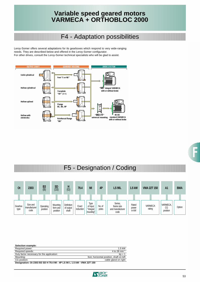
53
Variable speed geared motorsVARMECA + ORTHOBLOC 2000
F4 - Adaptation possibilities
Leroy-Somer offers several adaptations for its gearboxes which respond to very wide-rangingneeds. They are described below and offered in the Leroy-Somer configurator.For other drives, consult the Leroy-Somer technical specialists who will be glad to assist.
F5 - Designation / Coding
Selection example:
Required power: 1.5 kWRequired speeds: 4 to 28 min
–1
Duty factor necessary for the application: kp = 1Mounting: foot, horizontal position, shaft on leftCG position: cable gland on right
Designation: Ot 2303 B3 SD H
79.4 MI - 4P LS 90 L 1.5 kW - VMA 22T 150
Faceplate “BT” (B14)
Flange BS, BD, BP
Hollow withshrink disc
Hollow cylindrical
Hollow splined
Solid cylindricalFeet “S or NS”
Reinforced flange“BR”
VARME s syyCAOUTPUT SHAFT GEARBOX HOUSING DRIVE SYSTEM
“MI” integral VARMECA with or without brake
“MU-FF”universal mounting
B5 IEC standard VARMECA
with or without brake
Mountingform andposition
Definitionof output
shaft
Operatingposition
Gearboxtype
Ot
Size andmanufacturer
code
2303 B3(B)
SD(33) MI
Exactreduction
79.4
No. of poles
4P
Series,frame size
and manufacturercode
Typeof input"Integral
mounting"
LS 90L
Ratedpowerin kW
1.5 kW
VARMECArating
VMA 22T 150
VARMECA,CG
position
A1
Option
BMAH(G)

54
Orthobloc (Ot)
gearbox: foot mounted or
BT
(B14) faceplate form
VARMECA variable speed motors
: LS 4-pole, IP 65, class F- 3-phase
T
: 400 V -10% to 480 V +10%, 50-60 Hz ±10%- 3-phase
TL
: 200 V -10% to 240 V +10%, 50-60 Hz ±10%- Single-phase
M
: 200 V -10% to 240 V +10%, 50-60 Hz ±10%
Variable speed brake motors
: 4-pole, class F
FCR
: IP 55, from 0.25 to 4 kW
Variable speed geared motorsVARMECA + ORTHOBLOC 2000
F6 - Selection
Minimumoutputspeedmin–1
2.62.93.23.64
4.55.15.76.47.189
10.211.412.814.31620
25.628.63240
50.8
Maximumoutputspeedmin–1
182023252832364045505663718090100113141180201225281357
Reductionindex1251121009080716356504540
35.531.52825
22.42016
12.511.2108
6.3
2203
2303
2403
••
••
••
2703
2603
2503
21T110 22T150 22T180 22T220 22T300 22T400 14-550 14-750
90 L FCR 100 L FCR 112MG FCR NA NA3-phase 4-pole LS FCR J01 brake motor and frame size
3-phase VMA T 400/480 V
22TL110 22TL150 22TL180 22TL220 NA NA NA NA3-phase VMA TL 200/240 V
22M110
21T090
22TL090
22M090
21T075
21TL075
21M075
21T055
21TL055
21M055
21T037
21TL037
21M037
21T025
21TL025
21M025 22M150 NA NA NA NA NA NASingle phase VMA M 230 V
90 L
80 L FCR
80 L
71 L FCR
71 L 100 L 112 MG 132 SM 132 M
VARMECA variable speed motors, power kW
3-phase 4-pole LS motor and frame size1.10.25 0.37 0.55 0.75 0.9 1.5 1.8 2.2 3 4 5.5 7.5
18 to 357 min–1
Geared motors available only with MU universal mounting.•
Exact reduction
Indices
Type 125 112 100 90 80 71 63 56 50 45 40 35.5 31.5 28 25 22.4 20 16 12.5 11.2 10 9 8 6.3 5
2203
128 111 98.4 87.6 79.6 72.8 61.7 57.2 49.5 44.1 38.9 35.9 32 28.6 25.6 22.3 19.7 16.1 12.5 11.1 9.83 8.02 6.22
2303
85.4 79.4 69.4 61.3 54.6 49 44.2 39.5 34.8 31.9 27.6 24.5 22.2 20.1 16.5 12.3 11.4 10.1 9.14 8.27 6.8 5.07
2403
124 113 102 89 80.9 71.6 63.2 56.3 50.5 45 40.8 35.5 32.5 28.4 25.7 23.3 20.2 16.8 12.7 11.4 10.3 9.4 8.1 6.7 5.1
2503
127 116 99.2 91 79.1 69.6 62.5 55.3 49.8 45.1 39.2 35.9 31.5 28.1 26 22.3 20.4 16.3 12.5 11 10.1 8.1 6.2
2603
110 99.5 87.1 79.1 69.9 64.8 57.7 51.4 43.9 39.8 36.2 31.6 27.7 25.5 22.5 19.9 15.7 12.4 11.3 9.99 7.87 6.2
2703
127 110 99.5 87.1 79.1 69.9 64.8 57.5 51.4 43.9 39.8 36.2 31.6 27.7 25.5 22.5 19.9 15.7 12.4
2803
102 87.4 81 70.2 64.8 57.9 50.8 43.7 39.4 35.7 32.5 28.3 25.5 22.8 20.1 15.7 12.7
Integral mounting
MI
Universal mounting
MU-FF

55
Variable speed geared motorsVARMECA + ORTHOBLOC 2000
F7 - Dimensions
Dimensions of VARMECA + Orthobloc (Ot) gearboxes, MI integral mounting,Ot 2203 to Ot 2703
Dimensions in millimetres
SD
(S1 33)
or NSD
(NS1)
foot mounted form, shaft output on left L
1
(G)
Q
A
4 x K
AB
AA
GA
HA
AC
X
VLJJ
RLB
F
III
HJ
GE Y
CB
BB
H
HC
RA
DH
7
EYEX
O x Z
1.
R
(D): shaft extension identical to
L
(G).
LR
(X): both shaft extensions identical.2. Ot 2203 with A = 130 ie. 95 + 35 respectively on left and right of the output shaft extension.
1. In frame size 132, dimension I includes the control button supplied as standard.
Type
Gearboxes
Max.
A
2
AA AB B BB C G H HA HC K Q R RA V x yweight
kg
Ot 2703
420 100 490 270 320 35 170 250 45 480 24 255 565 515 310 30 175 210
Ot 2603
355 90 425 240 290 35 155 225 40 430 22 222 512 447 290 11 153 140
Ot 2503
280 70 350 230 280 33 148 200 40 375 24 185 417 415 232 21 147 73
Ot 2403
230 50 280 195 235 28.5 126 160 30 304 18 150 336 331 186 16 105 47
Ot 2303
170 43 216 155 190 27.5 105 125 20 242 14 120 294 278 174 13.5 92.5 26
Ot 2203
130
1
30 160 120 144 14 75 112 15 189 11 67 216 206 149 23 71 19
Type
Solid output shaft
D E EX EY F GA O ZOt 2703 90 m6 170 5 160 25 95 M24 50Ot 2603 70 m6 140 5 130 20 74.5 M20 42Ot 2503 60 m6 120 14 92 18 64 M20 42Ot 2403 50 k6 100 14 70 14 53.5 M16 36Ot 2303 40 k6 80 9 60 12 43 M16 36Ot 2203 30 j6 60 11 40 8 33 M10 22
Frame size
VARMECA variable speed motorsLS 3-phase LS and FCR brake
AC HJmax.
Jmax.LB
min.LJ I II
Max. weight
kg AC HJ hmax.
Jmax.LB
min.LJ I II
Max. weight
kg71 140 179 218 219 29 75 75 12.5 140 179 70 218 271 29 75 75 15.280 170 189 231 247 39 75 75 15.1 172 189 80 231 297 39 75 75 22.290 190 199 231 270 32 75 75 19.4 184 199 90 231 329 32 75 75 28.4100 200 204 231 331 44 75 75 26.7 200 204 98 231 393 44 75 75 34.2112 235 213 231 462 54 75 75 38.4 235 213 110 231 462 54 75 75 48.71321 280 282 324 439 56 112 112 61 - - - - - - - - -

56
Dimensions of VARMECA + Orthobloc (Ot) gearboxes, MI integral mounting,Ot 2203 to Ot 2703
Variable speed geared motorsVARMECA + ORTHOBLOC 2000
F7 - Dimensions
Dimensions in millimetresBT (B14 -44 or B14 -40) faceplate form, H (C) cylindrical hollow shaft
Type
Gearboxes with flange BT (B14 -44C) faceplate Max.
G H HC Q R V x Y IE M N P n α S Tweight
kgOt 2703 170 250 480 255 565 310 30 196 163 350 300 j6 400 81 22°30 M16x22.5 5 249Ot 2603 155 225 430 222 512 290 11 177 148 300 250 j6 350 81 22°30 M16x22.5 5 166Ot 2503 148 200 375 185 417 232 21 156 142 265 230 j6 300 8 22°30 M12x23 4 94Ot 2403 126 160 304 150 336 186 16 136 120 215 180 j6 250 4 45° M12x25 4 57Ot 2303 105 125 242 120 294 174 13.5 116 100 165 130 j6 200 4 45° M10x18 3.5 35Ot 2203 74 111 188 67 216 149 23 78 71 95 - - 6 60° M6x12 - 18.5
TypeHollow output shaft Driven shaft
D E EG F GA Z D1 min. DD E1 E4 E5 Z1Ot 2703 80 340 300 22 85.4 M30 95 80 j6 290 35 160 M20Ot 2603 70 310 270 20 74.9 M30 85 70 j6 260 35 130 M20Ot 2503 60 296 257 18 64.4 M24 72 60 j6 250 32 130 M20Ot 2403 50 252 219 14 53.8 M20 62 50 j6 210 28 100 M16Ot 2303 38 210 183 10 41.3 M16 50 38 j6 180 25 70 M12Ot 2203 35 148 121.5 10 38.3 M14 50 35 j6 116 - 148 M10
Frame size
VARMECA variable speed motorsLS 3-phase LS and FCR brake
AC HJmax.
Jmax.LB
min.LJ I II
Max. weight
kg AC HJ hmax.
Jmax.LB
min.LJ I II
Max. weight
kg71 140 179 218 219 29 75 75 12.5 140 179 70 218 271 29 75 75 15.280 170 189 231 247 39 75 75 15.1 172 189 80 231 297 39 75 75 22.290 190 199 231 270 32 75 75 19.4 184 199 90 231 329 32 75 75 28.4100 200 204 231 331 44 75 75 26.7 200 204 98 231 393 44 75 75 34.2112 235 213 231 462 54 75 75 38.4 235 213 110 231 462 54 75 75 48.71321 280 282 324 439 56 112 112 61 - - - - - - - - -
1. In frame size 132, dimension I includes the control button supplied as standard.
1. α = 7°30 in position V.
Q
n x S
GA
X
Vα
M
R
F
III
D1
Z1 Z
E1E4 E5
EGE
2,5 mm (45¡)
DDD
F
GA
D
H
7
NP
GT
Y
H
HC
E
IE
AC
LJJLB
HJ

57
Variable speed geared motorsVARMECA + ORTHOBLOC 2000
F7 - Dimensions
Dimensions of VARMECA + Orthobloc (Ot) gearboxes, MU universal mounting,Ot 2203 to Ot 2703
Dimensions in millimetres
PU
J LJH
JLB RU
AC
Framesize
VARMECA variable speed motors, MU universal mountingU-mounts
LS and VARMECA LS, VARMECA and brake Orthobloc (Ot) typemax. max. Weight max. max. Weight 2203 2303 2403 2503 2603 2703
AC HJ J LB LJ PU kg AC HJ J LB LJ PU kg RU RU RU RU RU RU71 140 175 218 183 8 160 12.5 140 175 218 271 8 160 15 116.5 116.5 79 79 - -80 170 189 231 215 12 200 15.1 172 189 231 292 12 200 22 126.5 126.5 89 89 111 -90 190 199 231 265 32 200 19.4 184 199 231 324 32 200 30 126.5 126.5 89 89 111 -100 200 204 231 290 12 250 26.7 200 204 231 372 12 250 36 136.5 136.5 99 99 121 198112 235 213 231 425 20 250 29 235 213 231 425 20 250 48 136.5 136.5 99 99 121 198132 280 282 324 387 16 300 61 - - - - - - - - - 119 119 141 218
Orthobloc (Ot) type2203 2303 2403 2503 2603 2703
Additional U-mount weight (kg) 6 6 8 16 28 75Max. permissible motor weight (kg) 70 70 120 150 250 350
Gearbox dimensions are given on the previous pages.

58
Variable speed geared motorsVARMECA + ORTHOBLOC 2000

59
Variable speed geared motorsVARMECA + MANUBLOC 2000
Manubloc 2000 speed reducers with parallelgears are used to adapt the speed of theelectric motor to that of the driven machine.Their size is therefore determined by themotor power (
P
) expressed in kilowatts (kW)and the output rotation speeds of thegearbox (n
min
-n
max
) in revolutions per minute(min
–1
).
The main characteristic of speed reducers isthe maximum rated output torque (M
n
max.)expressed in newton-metres (N.m):
M
n max.
=
×
efficiency
Six selected sizes: 21, 22, 23, 24, 25, 26.Rated output torque: from 10 N.m to 4770N.m.Selected power ratings: from 0.25 to 7.5 kW.Reduction ratios: 4.5 to 225.From two to three reduction stages.High efficiency: 95% to 97%.Reversible.Quiet operation.
P
×
9550n
max.
Component Materials Remarks
Frame Cast iron - use of GL cast iron (flake graphite: 150 MPa tensile strength) single componentperlite to ensure unit is fully sealed- monobloc ribbed with internal reinforcements to absorb vibrations and noise, andincrease its rigidity- foot mounted
NU
(N)
or with flanges
BT
(B14)
or
BS
(B5)
. They are compact andmeet industrial requirements
Gears Steel Ni Cr Mo - cut by the gear hob, they are heat treated and then undergo final machining. Thequality and precision of the gear cutting allow maximum torque with minimum noiselevel
Shaft Steel - grinding of sealing surfaces- hollow or cylindrical output with key in accordance with ISO R 773, or hollow withtaper bush- tolerance of diameters in accordance with NFE 22-051 and ISO R775- tapped holes at the shaft end for fixing connecting devices in accordance withDIN 332 version D
Lipseals Acrylonitrile- antidust lipseal in accordance with DIN 3760 form AS
End shield Cast iron- reinforced by large ribs, this ensures ruggedness of the gearbox under heavyloads
Lubrication Oil - in accordance with ISO 6743/6- delivered with the quantity of oil corresponding to the operating position indicatedon the order, it is fitted with drain, level and breather plugs
Mounting MI: geared motor with integrated motorMU: geared motor with IEC motor, manufactured with universal mounting
VARMECAvariable speed motor
VARMECA: single-phase power supply 200/240 V, 3-phase 200 V to 480 VLS motor: 3-phase 230/400 V- pressed steel fan cover, on request fitted with a drip cover for operation in verticalposition (shaft facing down = V1)- VARMECA casing in aluminium with cable gland supplied- VARMECA protection IP 65- motor protection IP 55, class F
VARMECA variable speed motor and brake
FCR: failsafe brake, from 0.25 to 4 kW, IP 55 protection (LS 71 to 112)
Finish Paint Shade: RAL 6000 (green), system
I
(1 polyurethane vinyl layer of 25/30 µm)
G2 - Construction
G1 - General

60
G3 - Mounting arrangements
Standard position: gearbox view from side F
(S3)
, motor behind, side D
(S1)
on the floor.
1 - Definition of mounting form: NU
(N)
flange: BT
(B14)
or BS
(B5)
NU
(N00)
BT
(40)
BS
(50) housing without holes (shaft mounting)
face mounted housing flange mounted (on housing with tapped holes)
2 - Definition of output shaft: H
(C)
or S
(P)
H
(C)
S
(P) cylindrical hollow output shaft cylindrical solid output shaft
5 - VARMECA positions 6 - Cable gland positions
A: Standard 1: Standard
3 - Options: SD
(F)
shrink disc TB
(B)
taper bush
SD
(F)
TB
(B) hollow output shaft with shrink disc hollow output shaft with taper bush
4 - Definition of operating position
4.1 - Mounting on NU
(N)
housing
B3
(P3)
B6
(P6)
B7
(P7)
B8
(P8)
V5
(PV5)
V6
(PV6)
B5
(P3)
B52
(P6)
B53
(P8)
B54
(P7)
V1
(PV5)
V3
(PV6)
4.2 - With BT
(B14)
, or BS
(B5)
flange
Variable speed geared motorsVARMECA + MANUBLOC 2000
A
C
BD13

61
Variable speed geared motorsVARMECA + MANUBLOC 2000
G4 - Adaptation possibilities
Leroy-Somer offers several adaptations for its gearboxes which respond to very wide-rangingneeds. They are described below and offered in the Leroy-Somer configurator.For other drives, consult the Leroy-Somer technical specialists who will be glad to assist.
G5 - Designation / Coding
Selection example:
Required power: 0.75 kWRequired speeds: 5.1 to 35 min
–1
Duty factor necessary for the application: kp = 1Mounting: foot, horizontal position, shaft on leftCG position: cable gland on right
Designation: Mub 2203 B5 BT H
(40C)
67.3 MI - 4P LS 80 L 0.75 kW - VMA 21T 075
Hollow withtaper bush
Standard pendulaire
Shaft mounting with BS flangewith clearance holes
Cylindrial hollow
Hollow withshrink disc
Cylindrical solid
OUTPUT SHAFT GEARBOX HOUSING DRIVE SYSTEM
NU standard shaftmounting
BT face mountingflange
“MI” integral VARMECA with or without brake
“MU-FF”universal mounting
B5 IEC standard VARMECA
with or without brake
Mountingform and position
Definitionof the output shaft
Operatingposition
Gearboxtype
Mub
Size andmanufacturer
code
2203 B5(P3)
BT(40) MI
Exactreduction
Typeof input
67.3
No. ofpoles
4P
Series,frame size
and manufacturercode
LS 80L
Rated power in kW
0.75 kW
VARMECArating
VMA 21T 075
VARMECA,CG
position
A1
Option
BMAH(C)

62
Variable speed geared motorsVARMECA + MANUBLOC 2000
G6 - Selection
Minimumoutputspeedmin–1
1.41.61.72
2.32.62.93.23.64
4.55.15.76.47.189
10.211.412.814.316
17.820
22.925.628.632
35.640455771
Maximumoutputspeedmin–1
1011.212.51416182022252831354045505663718090100113125141161180201225250281317402500
Reduction index2252001801601401251121009080716356504540
35.531.52825
22.420181614
12.511.21098
7.15.64.5
2202
2102
22032303 2403
2402
2402
2302
•
•2503
2503
2503
2503
2603
21T110 22T150 22T180 22T220 22T300 22T400 14-550 14-750
90 L FCR 100 L FCR 112MG FCR NA NA3-phase 4-pole LS FCR J01 brake motor and frame size
3-phase VMA T 400/480 V
22TL110 22TL150 22TL180 22TL220 NA NA NA NA3-phase VMA TL 200/240 V
22M110
21T090
22TL090
22M090
21T075
21TL075
21M075
21T055
21TL055
21M055
21T037
21TL037
21M037
21T025
21TL025
21M025 22M150 NA NA NA NA NA NASingle phase VMA M 230 V
90 L
80 L FCR
80 L
71 L FCR
71 L 100 L 112 MG 132 SM 132 M
VARMECA variable speed motors, power kW
3-phase 4-pole LS motor and frame size1.10.25 0.37 0.55 0.75 0.9 1.5 1.8 2.2 3 4 5.5 7.5
from 10 to 500 min–1
Geared motors available only with MU universal mounting.•
Exact reduction Indices
Type 225 200 180 160 140 125 112 100 90 80 71 63 56 50 45 40 35.5 31.5 28 25 22.4 20 18 16 14 12.5 11.2 10 9 8 7.1 6.3 5.6 5 4.5
2102
73.9 64.1 56.9 50.7 46.1 42.1 35.7 33.1 28.7 25.5 22.5 20.8 18.5 16.5 14.8 12.9 11.4
22--
207 184 168 153 130 120 104 92.7 81.8 75.6 67.3 60.1 53.9 47 41.5 29.9 27.8 24.3 21.5 19.1 17.2 15.5 13.8 12.2 11.2 9.66 8.59 7.76 7.03 5.78 4.3
23--
214 199 174 154 137 123 111 99.2 87.4 79.9 69.2 61.6 53.7 49.1 44.1 38.6 35.1 31 27.4 24.4 21.9 19.5 17.7 15.4 14.1 12.3 11.1 10.1 8.76 7.26 5.49
24--
233 212 191 167 152 134 119 106 94.8 84.5 76.6 66.6 60.9
*
44 37.7 34.6 30.1 26.5 23.8 21 19 17.2 14.9 13.6 12 10.7 9.91 8.48 7.76 6.22 4.77
25--
213 184 167 146 133 117 109 96.4 86.1 73.6 66.7 60.6 52.9 46.4 42.7 37.7 32.1 27.7 25.2 22 20 17.7 16.4 14.6 13 11.1 10.1 9.15 7.99 7.01 6.44 5.69 5.04
26--
200 173 157 137 125 110 102 90.7 81 69.2 62.7 57 49.8 43.7 40.2 35.4 31 28.1 24.9 23.1 20.4 18.3 15.6 14.1 12.9 11.2 10.3 9.05 8 7.08
Manubloc (Mub) gearbox
:
NU
(N) plain form,
BT
(B14) faceplate or
BS
(B5) flange
VARMECA variable speed motors
: LS 4-pole, IP 65, class F- 3-phase
T
: 400 V -10% to 480 V +10%, 50-60 Hz ±10%- 3-phase
TL
: 200 V -10% to 240 V +10%, 50-60 Hz ±10%- Single-phase
M
: 200 V -10% to 240 V +10%, 50-60 Hz ±10%
Variable speed brake motors
: 4-pole, class F
FCR
: IP 55, from 0.25 to 4 kW
Integral mounting
MI
Universal mounting
MU-FF
*. Mub 2402 exact reduction = 48.2 Mub 2403 exact reduction = 53.2

63
Variable speed geared motorsVARMECA + MANUBLOC 2000
G7 - Dimensions
Dimensions of VARMECA + Manubloc (Mub) gearboxes, MI integral mounting,Mub 2102 to Mub 2603
Dimensions in millimetres
NU
(00)
housing form, H
(C)
cylindrical hollow output shaft
LB
HJ
AC
JLJ III
R
E
x
DH
7
OR
F
HC
GA
H
AA
YB
Y
Z
W
E3E2
EG
EHE
Z2
Details of the hollow output shaft
1. In frame size 132, dimension I includes the control button supplied as standard.
Type
Gearboxes Hollow output shaft
Max.
AA H HC OR R W x Y Z YB D E E2 E3 EG EH F GA Z2weight
kg
Mub 2603
415 190 675 33 307 8 285 75 410 40 70 365 225 140 325 348 20 74.9 M30 225
Mub 2503
350 150 565 24 236 5 256 62 346 30 60 288 208 80 243 267 18 64.4 M24 119
Mub 2402-2403
272 138 450 22 203 4 208 50 278 25 50 253.5 183 70 220.5 240.5 14 53.8 M20 59
Mub 2302-2303
264 126 400 14 159.5 4 178 39 250 20 40 193.5 130 60 155 168.5 12 43.3 M20 40
Mub 2202-2203
208 93 305 14 138 3.5 135 32 170 25 30 174 134 40 149.5 160.5 8 33.3 M14 22
Mub 2102
184 95 295 14 110 3.5 125 32 170 15 30 113 83 30 91 102 8 33.3 M14 17
Frame size
VARMECA variable speed motorsLS 3-phase LS and FCR brake
AC HJmax.
Jmax.LB
min.LJ I II
Max. weight
kg AC HJ hmax.
Jmax.LB
min.LJ I II
Max. weight
kg
71
140 179 218 219 29 75 75 12.5 140 179 70 218 261 29 75 75 15.2
80
170 189 231 247 39 75 75 15.1 172 189 80 231 297 39 75 75 22.2
90
190 199 231 270 32 75 75 19.4 184 199 90 231 330 32 75 75 28.4
100
200 204 231 337 44 75 75 26.7 200 204 98 231 399 44 75 75 34.2
112
235 213 231 462 49 75 75 38.4 235 213 110 231 462 49 75 75 48.7
132
1
280 282 324 439 56 112 112 61 - - - - - - - - -

64
Variable speed geared motorsVARMECA + MANUBLOC 2000
G7 - Dimensions
Dimensions of VARMECA + Manubloc (Mub) gearboxes, MI integral mounting,Mub 2102 to Mub 2603
Dimensions in millimetres
BT
(40)
face mounted housing form, H
(C)
cylindrical hollow output shaft
Type
Gearboxes with faceplate Hollow output shaft
Max.
A AA B BB C f H HC OR R x Y YB Z D E E2 E3 EG EH F GA W Z2weight
kg
Mub 2603
34 400 165 215 45 16 190 675 33 292 285 60 40 410 70 365 225 140 325 348 20 74.9 15 M30 220
Mub 2503
22 340 165 205 30 18 150 565 24 226 256 52 30 346 60 288 208 80 243 267 18 64.4 10 M24 119
Mub 2402-2403
35 265 100 155 35 20 138 450 22 195 208 42 25 278 50 253.5 183 70 220.5 240.5 14 53.8 8 M20 59
Mub 2302-2303
10 256 110 130 20 10 126 400 14 150 178 31.5 20 250 40 193.5 130 60 155 168.5 12 43.3 7.5 M20 40
Mub 2202-2203
40 192 70 120 17 10 93 305 14 131 135 26.5 25 170 30 174 134 40 149.5 160.5 8 33.3 7 M14 22Mub 2102 - 184 * * * * 90 290 14 102.5 125 25 15 170 30 113 83 30 91 102 8 33.3 7.5 M14 17
TypeHousing and BT (B14) flange drill holes
HA HB HD HE HF K.U M N ON.Q T a n x S.TMub 2603 70 245 40 315 320 M16.25 300 250 M30.45 5 22°5 81 x M16.25Mub 2503 100 200 56 300 265 M16.24 215 180 M24.45 5 30° 62 x M12.20Mub 2402-2403 85 155 53 240 215 M16.24 180 160 M24.45 4 30° 6 x M12.20Mub 2302-2303 62 138 40 200 193 M12.18 165 130 M24.30 3.5 30° 6 x M10.18Mub 2202-2203 56 94 41 150 135 M8.14 130 110 M16.34 3.5 45° 4 x M8.16Mub 2102 - - - - - - 115 95 - 3.5 45° 4 x M8.12
Frame size
VARMECA variable speed motorsLS 3-phase LS and FCR brake
AC HJmax.
Jmax.LB
min.LJ I II
Max. weight
kg AC HJ hmax.
Jmax.LB
min.LJ I II
Max. weight
kg71 140 179 218 219 29 75 75 12.5 140 179 70 218 261 29 75 75 15.280 170 189 231 247 39 75 75 15.1 172 189 80 231 297 39 75 75 22.290 190 199 231 270 32 75 75 19.4 184 199 90 231 330 32 75 75 28.4100 200 204 231 337 44 75 75 26.7 200 204 98 231 399 44 75 75 34.2112 235 213 231 462 49 75 75 38.4 235 213 110 231 462 49 75 75 48.71321 280 282 324 439 56 112 112 61 - - - - - - - - -
1. In frame size 132, dimension I includes the control button supplied as standard.
*. Non-machined sides.
1. 7 equidistant holes at 45° + 1 hole top right at 35°.2. 5 equidistant holes at 60° + 1 hole top right at 45°.
R
E
x
DH
7
OR
HB
HA
E3E2
EGEHE
Z2
YB
Y
HE
HD
Z
N
BB
AB
f
CW
T8 x K . U
LB
HJ
AC
JLJ III
O . Q
n x S.T
F
M
a
HC
GA
H
AA
HF

65
Dimensions of VARMECA + Manubloc (Mub) gearboxes, MI integral mounting,Mub 2202 to Mub 2603
Type
Gearboxes with flange Hollow output shaft Max.
AA H HC LA M N P R T a n x S x D E E2 E3 EG EH F GA W Z2weight
kgMub 2603 400 190 675 20 400 350 450 352 5 22°30 8 x 18 285 70 365 225 140 325 348 20 74.9 45 M30 240Mub 2503 340 150 565 20 300 250 350 313 5 45° 4 x 18 256 60 288 208 80 243 267 18 64.4 77 M24 134Mub 2402-2403 265 138 450 15 265 230 300 240 3 45° 4 x 14 208 50 253.5 183 70 220.5 240.5 14 53.8 37 M20 69Mub 2302-2303 256 126 400 15 265 230 300 195 3 45° 4 x 14 178 40 193.5 130 60 155 168.5 12 43.3 37.5 M20 48Mub 2202-2203 192 93 305 15 215 180 250 166.5 3 45° 4 x 14 135 30 174 134 40 149.5 160.5 8 33.3 28 M14 27
Type
Other possible flangeBD1 flange
AA H HC LA M N P R T a n x S xMub 2402-2403 265 138 450 15 215 180 250 261 3 45° 4 x 14 208Mub 2302-2303 256 126 400 15 215 180 250 216 3 45° 4 x 14 178Mub 2102 192 93 305 15 165 130 200 189 3 45° 4 x 14 135
Frame size
VARMECA variable speed motorsLS 3-phase LS and FCR brake
AC HJmax.
Jmax.LB
min.LJ I II
Max. weight
kg AC HJ hmax.
Jmax.LB
min.LJ I II
Max. weight
kg71 140 179 218 219 29 75 75 12.5 140 179 70 218 261 29 75 75 15.280 170 189 231 247 39 75 75 15.1 172 189 80 231 297 39 75 75 22.290 190 199 231 270 32 75 75 19.4 184 199 90 231 330 32 75 75 28.4100 200 204 231 337 44 75 75 26.7 200 204 98 231 399 44 75 75 34.2112 235 213 231 462 49 75 75 38.4 235 213 110 231 462 49 75 75 48.71321 280 282 324 439 56 112 112 61 - - - - - - - - -
Variable speed geared motorsVARMECA + MANUBLOC 2000
G7 - Dimensions
1. In frame size 132, dimension I includes the control button supplied as standard.
Dimensions in millimetres BS, BD1 (50) flange mounting housing form, H (C) cylindrical hollow output shaft
R
E
x
DH
7
T LA
W
OR
HB
HA
E3E2
EGEHE
Z2
LBH
J
AC
JLJ III
n x S
P
FNa
HC
GA
H
AA
M

66
Variable speed geared motorsVARMECA + MANUBLOC 2000
G7 - Dimensions
Dimensions of VARMECA + Manubloc (Mub) gearboxes, MU universal mounting,Mub 2102 to Mub 2603
Dimensions in millimetres
JLJ
HJ
LBRU
PUAC
Framesize
VARMECA variable speed motors, MU-FF universal mountingU-mounts
LS and VARMECA LS, VARMECA and brake Manubloc (Mub) typemax. max. Weight max. max. Weight 2102 22-- 23-- 24-- 25-- 26--
AC HJ J LB LJ PU kg AC HJ J LB LJ PU kg RU RU RU RU RU RU71 140 179 218 183 8 160 12.5 140 179 218 271 8 160 15 116.5 116.5 79 79 - -80 170 189 231 215 12 200 15.1 172 189 231 292 12 200 22 126.5 126.5 89 89 111 -90 190 199 231 265 32 200 19.4 184 199 231 324 32 200 30 126.5 126.5 89 89 111 -100 200 204 231 290 12 250 26.7 200 204 231 372 12 250 36 136.5 136.5 99 99 121 198112 235 213 231 425 20 250 37.5 235 213 231 425 20 250 48 136.5 136.5 99 99 121 198132 280 282 324 387 16 300 60.8 - - - - - - - - - 119 119 141 218
Manubloc (Mub) type21-- 22-- 23-- 24-- 25-- 26--
Additional U-mount weight (kg) 4 6 8 16 28 65Max. permissible motor weight (kg) 65 70 120 150 250 400
Gearbox dimensions are given on the previous pages.

67
Variable speed geared motorsVARMECA + MULTIBLOC 2100
H1 - General
Multibloc 2100 geared motors with wormgears are used to adapt the speed of theelectric motor to that of the driven machine.Their size is therefore determined by themotor power (
P
) expressed in kilowatts (kW)and the output rotation speed of the gearbox(n
S
) in revolutions per minute (min
–1
).
The main characteristic of speed reducers isthe rated output torque (M
nS
) expressed innewton-metres (N.m).
M
nS
=
×
efficiency
Rated output torque: from 5 N.m to 55 N.m.Power ratings: from 0.25 to 0.55 kW.Reduction ratios: from 7.5 to 100.Efficiency: 45% to 84%.Quiet operation.
P
×
9550n
S
Component Materials Remarks
Frame Aluminium - monobloc - multi-position- die-cast aluminium- heavily ribbed to improve the mechanical resistance and thermal dissipation
Worm
Wheel
Steel
Bronze
- worm in tempered steel, ground sides
- wheel in centrifuged bronze
Shaft Steel - grinding of sealing surfaces- key in accordance with DIN 6883- tolerance of diameters in accordance with IEC 72-1 (DIN 748)- for output shaft, tapped hole on shaft extension
Lipseals Acrylonitrile - monobloc housing, shaft seals ensure dust and damp protection- no hole opening into the housing
Lubrication Synthetic oil - delivered with the quantity of oil corresponding to multi-position operation- maintenance-free, lubricated for the lifetime of the gearbox- no drain, level or fill plug- vent hole on request
MountingMU: geared motor with IEC motor, manufactured with universal mounting
VARMECA variable speed motor
VARMECA: single-phase power supply 230 V, 3-phase 230 V to 480 VLS motor: 3-phase 230/400 V- pressed steel fan cover, on request fitted with a drip cover for operation in verticalposition (shaft facing down = V1)- VARMECA casing in aluminium with cable gland supplied- VARMECA protection IP 65- motor protection IP 55, class F
VARMECA variable speed motor and brake FMC: 3-phase or single-phase failsafe brake induction motor, from 0.25 to 0.37 kW
FCR: 3-phase failsafe brake induction motor, from 0.25 to 0.55 kW
Finish Paint Shade: RAL 6000 (green), system
I
(1 polyurethane vinyl layer of 25/30 µm)
H2 - Construction

68
Variable speed geared motorsVARMECA + MULTIBLOC 2100
H3 - Mounting arrangements
Standard Multibloc 2101 N multi-position M00
B00 P00 H00 T00 V00 W00
Positions to be specified only if it is necessary to provide vent, fill, level or drain hole.
Standard Multibloc 2101 with BS flanges multi-position M50 or M05 or M55
5 - VARMECA positions 6 - Cable gland positions
A: Standard 1: Standard
Standard Multibloc 2101 with torque arm multi-position M70 or M07
B50 P50 H50 T50 V50 W50
Other flange positions: on the right (eg.: B05, on both sides (eg.: B55).Positions to be specified only if it is necessary to provide vent, fill, level or drain hole.
B70 P70 H70 T70 V70 W70
Other torque arm positions: on right (eg.: B07).Positions to be specified only if it is necessary to provide vent, fill, level or drain hole.
13
A
C
BD

69
Variable speed geared motorsVARMECA + MULTIBLOC 2100
H4 - Adaptation possibilities
Leroy-Somer offers several adaptations for its gearboxes which respond to very wide-rangingneeds. They are described below and offered in the Leroy-Somer configurator.For other drives, consult the Leroy-Somer technical specialists who will be glad to assist.
OUTPUT SHAFT GEARBOX HOUSING DRIVE SYSTEM
Torque arm
Hollow cylindrical
Solid cylindricalon left or right
Solid cylindrical with flangeon left or right
Solid cylindrical dual
Flange (BS)
Standard“MU-FT”
universal mountingB14 IEC
standard VARMECAwith or without brake
H5 - Designation / Coding
Selection example:
Required power: 0.37 kWRequired speeds: 13.9 to 92.8 min
–1
Duty factor necessary for the application: kp = 1Mounting: footCG position: cable gland on right
Designation: Mb 2101 M00C
25 MU - 4P LS 71 0.37 kW - VMA 21M 037
Mountingform
Definition of the outputshaft
Operatingposition
Gearboxtype
Mb
Size andmanufacturer
code
2101 M 00
Exactreduction
Universalmounting
25
No. ofpoles
4P
Series,frame size
LS 71
Ratedpowerin kW
0.37 kW
VARMECArating
VMA 21M 037
VARMECA,CG
position
A1
Option
BMAC MU-FT

70
Variable speed geared motorsVARMECA + MULTIBLOC 2100
H6 - Selection
Maximumoutputspeedmin–1
23.229
38.746.458
77.392.8116155186232309
Minimumoutputspeedmin–1
3.484.355.86.968.711.613.917.423.227.834.845.8
Exactreduction
1008060504030252015
12.5107.5
21T025 21T037
21TL025 21TL037
21M025 21M037
3-phase 4-pole LS brake motor and frame size
3-phase VMA -- T --- 400/480 V
3-phase VMA -- TL --- 200/240 V
Single phase VMA -- M --- 200/240 V
71
VARMECA variable speed motors, power kW
3-phase 4-pole LS motor and frame size0.25 0.37
71 FMC ou 71 L FCR
Mb 2101 from 23.2 to 309 min–1
Multibloc (Mb) gearbox
:
S
(M00) or
BS L
(M50) or with
BS R
(M05) flange
VARMECA variable speed motors
: LS 4-pole, IP 65, class F- 3-phase
T
: 400 V -10% to 480 V +10%, 50-60 Hz ±10%- 3-phase
TL
: 200 V -10% to 240 V +10%, 50-60 Hz ±10%- Single-phase
M
: 200 V -10% to 240 V +10%, 50-60 Hz ±10%
Variable speed brake motors
: 4-pole, class F
FCR
: IP 55, from 0.25 to 0.37 kW
FMC
: IP 44, from 0.25 to 0.37 kW
Universal mounting
MU-FT

71
Variable speed geared motorsVARMECA + MULTIBLOC 2100
H7 - Dimensions
Dimensions of VARMECA + Multibloc (Mb) gearbox,MU-FT universal mounting IM3601 (IM B14),
Mb 2101
Dimensions in millimetres
(M00)
standard form,
(C)
hollow output shaft.
XA
6 x S1
XA
XB
IT IT
II
XA XACP
E
DH
7
MC
NJ6
II I
XAXA
XA XA 4 x S1
4 x S2 / M2
4 x X
GA
x
HF
HA
HA
HA
HCF
V
HG
HU
R
PU
J LJ
HJ
LB RU
AC
Type
Gearboxes Hollow output shaft
Max.
HA HC HF HG HU IE IN IT M2 PU R RU S1 S2 V XA XB XC x D E F GA MC CPweight
kg
Mb 2101
6 130 50 50 80 43 68 3 85 105 110 15 6.5 M6x15 50 31.5 58.5 31.5 40 20 90 6 22.8 40 20 3
Frame size
VARMECA variable speed motorsLS 3-phase LS and FMC brake LS and FCR brake
AC LB LJ J
HJ I II
Max. weight
kg AC HJ J
max.LB
min.LJ I II
Max. weight
kg AC HJ J
max.LB
min.LJ I II
Max. weight
kg
LS 71
140 193 8 217 195 75 75 9.5 140 195 217 243 8 75 75 10.5 140 195 217 245 8 75 75 14.2

72
Variable speed geared motorsVARMECA + MULTIBLOC 2100
H7 - Dimensions
Dimensions of VARMECA + Multibloc (Mb) gearbox,MU-FT universal mounting IM3601
(IM B14)
,Mb 2101
Dimensions in millimetres
(M50)
,
(M05)
flange form,
(C)
hollow output shaft.
Type
Gearboxes BS flange
Max.
R RB AB PU RD RU HF x HU HG IE IA V M N P S LA Tweight
kg
Mb 2101
110 130 100 105 112 15 50 40 80 50 43 75 70 100 80 120 7 8 3 3.3
Type
Other possible flanges
1
BD1 flange BD2 flange
M1 N1 P1 S1 LA1 T1 M2 N2 P2 S2 LA2 T2
Mb 2101
85 70 105 7 8 3 115 95 140 9 8 3
Type
Hollow output shaft
D E GA F CP
Mb 2101
20 90 22.8 6 20.5
Frame size
VARMECA variable speed motorsLS 3-phase LS and FMC brake LS and FCR brake
AC LB LJ J
HJ I II
Max. weight
kg AC HJ J
max.LB
min.LJ I II
Max. weight
kg AC HJ J
max.LB
min.LJ I II
Max. weight
kg
LS 71
140 193 8 217 195 75 75 9.5 140 195 217 243 8 75 75 10.5 140 195 217 245 8 75 75 14.2
1. The letters are numbered to distinguish them from the letters on the standard flange diagram.
MC
IN j6
I
IT
II I
D H
7
P
N j6
G
LAT
W
I
E
IA
RU RD ED
HF
R
GA
AB
PU 4 x S / M
Hx
F
HU
DD
j6
D x
ZD
HC
On requestJ LJ
HJ
LB
AC

73
Multibloc 2000 speed reducers with wormgear are used to adapt the speed of theelectric motor to that of the driven machine.Their size is therefore determined by themotor power (
P
) expressed in kilowatts (kW)and the output rotation speeds of thegearbox (n
min
-n
max
) in revolutions per minute(min
–1
).
The main characteristic of speed reducers isthe maximum rated output torque (M
n
max.)expressed in newton-metres (N.m):
M
n max.
=
×
efficiency
Six selected sizes: 31, 22, 23, 24, 25, 26.Rated output torque: from 20 N.m to 570 N.m.Selected power ratings: from 0.25 to 7.5 kW.Reduction ratios: 7.3 to 100.From two to three reduction stages.High efficiency: 55% to 88%.Quiet operation.
I2 - Construction
Variable speed geared motorsVARMECA + MULTIBLOC 2000
I1 - General
P
×
9550n
max.
Component Materials Remarks
Frame Cast iron - use of GL cast iron (flake graphite: 150 MPa tensile strength) single componentperlite to ensure unit is fully sealed- monobloc ribbed with internal reinforcements to absorb vibrations and noise, andincrease its rigidity- with
NU
(N) housing, it can be adapted for sizes 22, 23, 24, 25 by using the footmounting kit
S
or flanges
BS
,
BD
or torque arm
R
. They are compact and meetindustrial requirements
Wheel
Worm
Bronze
Steel
- moulded on a steel or cast iron insert, wedged against the worm, supported by twolarge-diameter bearings without intermediate shields (except Mb 26).
- cut on a whirl lathe, toughened and ground
Shaft Steel - grinding of sealing surfaces- hollow or cylindrical output with key in accordance with ISO R 773, normal key andprotective cover- tolerance of diameters h6- tapped hole at the shaft end for fixing connecting devices in accordance withDIN 332 version DR
Lipseals Nitrile - antidust lipseal in accordance with DIN 3760 form AS- ground and toughened sealing surfaces on worm
End shield Cast iron- on size 26, reinforced by large ribs, this ensures ruggedness of the gearbox underheavy loads
Lubrication Oil - in accordance with ISO 6743/6- delivered with the quantity of oil corresponding to multi-position operation, it isfitted with drain, level and breather plugs (except Mb 31)
MountingMU: geared motor with IEC motor
VARMECA variable speed motor
VARMECA: single-phase power supply 200/240 V, 3-phase 200 V to 480 VLS motor: 3-phase 230/400 V- pressed steel fan cover, on request fitted with a drip cover for operation in verticalposition (shaft facing down = V1)- VARMECA casing in aluminium with cable gland supplied- VARMECA protection IP 65- motor protection IP 55, class F
VARMECA variable speed motor and brake
FCR: failsafe brake, from 0.25 to 4 kW, IP 55 protection
Finish Paint Shade: RAL 6000 (green), system
I
(1 polyurethane vinyl layer of 25/30 µm)

74
Variable speed geared motorsVARMECA + MULTIBLOC 2000
I3 - Mounting arrangements
Standard position: gearbox view from side F
(S3)
, motor behind, side D
(S1)
on the floor.
1 - Definition of mounting form: NU
(N)
NS
(S)
feet except for Mb 3101 flange mounted
NU
(N)
NS D
(S1 00 -
NS F
(S3 00 -
NS U
(S5 00 -
NS K
(S0)
BS L
(BS50-
BD L
(BD50)
BN L
(BN50)all sides
S1 33
for
Mb26) S3 33
for
Mb26 S5 33
for
Mb26 feet not BS53
for
Mb26) BS53
for
Mb26) flange withwith tapped holes
feet fixed on feet fixed on feet fixed on fitted flange with flange with clearance
[except Mb 3101: side
D
(1) side
F
(3) side
U
(5) supplied in clearance clearance holes holesside
F
(3) option, a kit holes on left (different diameter) on left except side
U
(5) on leftand Mb 26-- except Other flange positionsides
L
(G) and
R
(D)] on right
R
(05 - 35 for Mb 26), supplied in a kit
--K
2 - Definition of output shaft 3 - Option: R
(R)
torque arm
H
(C)
H L
(G)
H R
(D)
H LR
(X)
RK
(00 R0)hollow cylindrical solid cylindrical solid cylindrical 2 solid cylindrical torque arm not fitted shaft shaft shaft shafts supplied in a kit output on left output on right output on left and right
5 - VARMECA positions 6 - Cable gland positions
A: Standard 1: Standard
4 - Definition of operating position
4.1 - NU
(N)
housing, NSD
(S1)
, NSF
(S3)
, NSU
(S5)
foot mounted, or R
(R)
torque arm
B3
(B--)
B6
(W--)
B7
(V--)
B8
(P--)
V5
(H--)
V6
(T--)
B5
(B--)
B52
(W--)
B53
(P--)
B54
(V--)
V1
(H--)
V3
(T--)
4.2 - With BS, BN or BD flange
A
C
BD 13

75
I5 - Designation / Coding
Variable speed geared motorsVARMECA + MULTIBLOC 2000
I4 - Adaptation possibilities
Leroy-Somer offers several adaptations for its gearboxes which respond to very wide-rangingneeds. They are described below and offered in the Leroy-Somer configurator.For other drives, consult the Leroy-Somer technical specialists who will be glad to assist.
Mountingform
Definitionof theoutputshaft
Mountingposition
Operatingposition
Gearboxtype
Mb
Size andmanufacturer
code
2401 B3(B)
NS(S)
Exact reduction
Typeof input
50
No. ofpoles
4P
Series,frame size and manufacturer
code
LS 90 L
Ratedpowerin kW
1.5 kW
VARMECArating
VMA 22T 150
VARMECA,CG
position
A1
Option
BMAH(C)
MU-FT(MU B14)
D(1)
Hollow cylindrical NU (N) standard
NS (S) feet
BS, BN, BD flange
Torque armsupplied in kit RK (00 R0)
Solid cylindrical on left or right
Solid cylindrical with flange on left or right
Solid cylindrical dual
OUTPUT SHAFT GEARBOX HOUSING DRIVE SYSTEM
“MU”universal mounting
B5 or B14 IEC standard VARMECA
with or without brake
Selection example:
Required power: 1.5 kWRequired speeds: 6.4 to 45 min
–1
Duty factor required by the application: kp = 1Mounting: foot, on floor, hollow shaftCG position: cable gland on right
Designation: Mb 2401 B3 NSD H
50 MU-FT - 4P LS 90 L 1.5 kW - VMA 22T 150 A1
(Mb 2401 S1 B00C 50 MU B14 - 4P LS 90 1.5 kW - VMA 12 150 BD)

76
Variable speed geared motorsVARMECA + MULTIBLOC 2000
I6 - Selection
Minimumoutputspeedmin–1
3.34
5.46.48
10.712.616.121.531.144
Maximumoutputspeedmin–1
23283845567588113150218308
Reductionindex1008060504030
25.52015
10.37.3
2301
2201
2201
2201
2201
2201
3101
2401
2401
24012601
2601
2501
21T110 22 T150 22T180 22T220 22T300 22T400 14-550 14-750
90 L FCR 100 L FCR 112MG FCR NA NA3-phase 4-pole LS FCR J01 brake motor and frame size
3-phase VMA T 400/480 V
22TL110 22TL150 22TL180 22TL220 NA NA NA NA3-phase VMA TL 200/240 V
22M110
21T090
22TL090
22M090
21T075
21TL075
21M075
21T055
21TL055
21M055
21T037
21TL037
21M037
21T025
21TL025
21M025 22M150 NA NA NA NA NA NASingle phase VMA M 230 V
90 L
80 L FCR
80 L
71 L FCR71 L FCR
71 L 100 L 112 MG1 132 SM1 132 M1
VARMECA variable speed motors, power kW
3-phase 4-pole LS motor and frame size1.10.25 0.37 0.55 0.75 0.9 1.5 1.8 2.2 3 4 5.5 7.5
23 to 308 min–1
3101 < Motor with frame size 80 mounted on Mb 3101 with flange B14 face-mounted 85 and shaft extension 14 x 30, obligatory.2201 < Motor with frame size 90 mounted on Mb 2201 with flange B5 flange-mounted 130 and shaft extension 19 x 40, adapted.2301 < Motors with frame size 100 and 112 mounted on Mb 2301 with flange B5 flange-mounted 165 and shaft extension 24 x 50, adapted.2601 < Motor with frame size 132 mounted on Mb 2601 with flange B5 flange-mounted 165 and shaft extension 28 x 60, adapted.
1. Variable speed motors available with preferential delivery terms with B5 mounting only.
<<<<
<<<<
<<<
<<<
<< <
<<<
<<
<<
<<
<<
<<
<
<<
<<
<
<<
Exact reduction IndicesType 100 80 60 50 40 30 25.5 20 15 10.3 7.3
Mb 2601
100 80 60 50 40 30 25.5 20.5 15.5 10.3 7.5
Mb 2501
100 80 60 50 40 30 25.5 20.5 15.5 10.3 7.25
Mb 2401
100 80 60 50 40 30 25.5 19.5 14.5 10.3 7.25
Mb 2301
100 80 60 50 40 30 25.5 20 15 10.3 7.5
Mb 2201
100 80 60 50 40 30 25.5 20 15 10.3 7.33
Mb 3101
100 80 60 50 40 30 25 20 15 10 7.5
Multibloc (Mb) gearbox
:
NU
(N) standard,
NS
(S) foot mounted or
BS
,
BD
or
BN
flange form
VARMECA variable speed motors
: LS 4-pole, IP 65, class F- 3-phase
T
: 400 V -10% to 480 V +10%, 50-60 Hz ±10%- 3-phase
TL
: 200 V -10% to 240 V +10%, 50-60 Hz ±10%- Single-phase
M
: 200 V -10% to 240 V +10%, 50-60 Hz ±10%
Variable speed brake motors
: 4-pole, class F
FCR
: IP 55, from 0.25 to 4 kW
Universal mounting
MU-FT or MU-FF
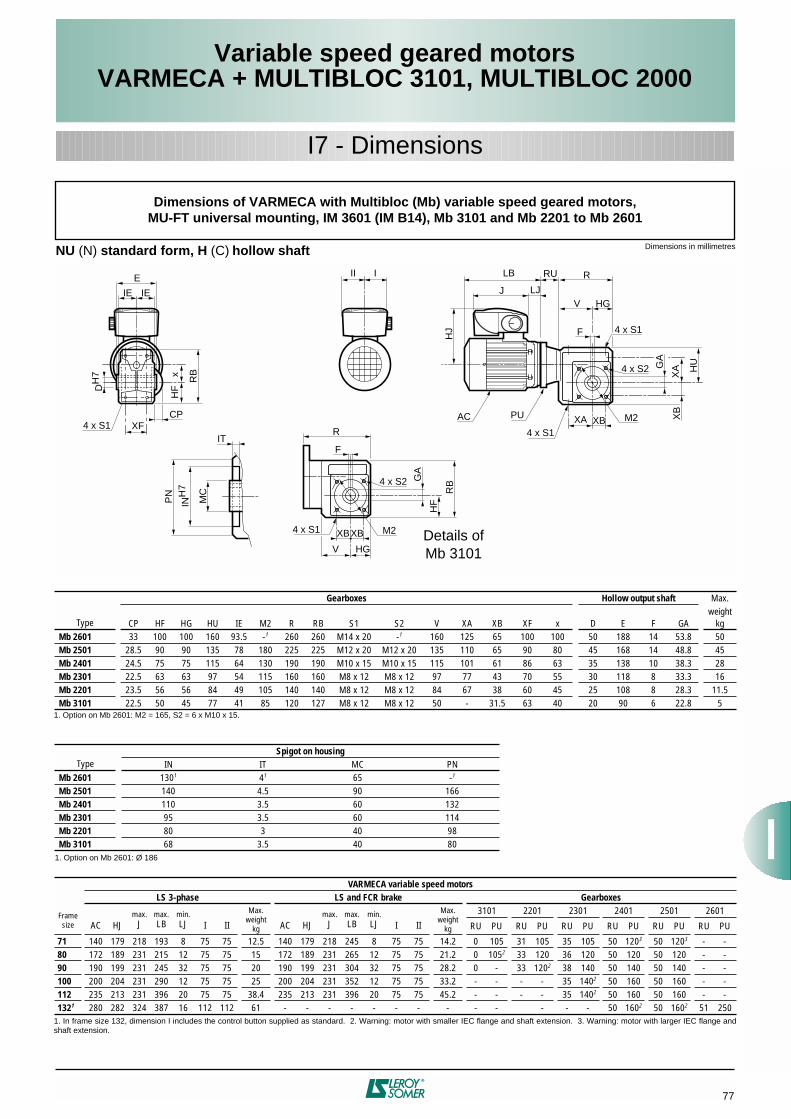
77
Variable speed geared motorsVARMECA + MULTIBLOC 3101, MULTIBLOC 2000
I7 - Dimensions
Dimensions of VARMECA with Multibloc (Mb) variable speed geared motors,MU-FT universal mounting, IM 3601 (IM B14), Mb 3101 and Mb 2201 to Mb 2601
Dimensions in millimetres
NU
(N)
standard form, H
(C)
hollow shaft
Type
Gearboxes Hollow output shaft
Max.
CP HF HG HU IE M2 R RB S1 S2 V XA XB XF x D E F GAweight
kg
Mb 2601
33 100 100 160 93.5 -
1
260 260 M14 x 20 -
1
160 125 65 100 100 50 188 14 53.8 50
Mb 2501
28.5 90 90 135 78 180 225 225 M12 x 20 M12 x 20 135 110 65 90 80 45 168 14 48.8 45
Mb 2401 24.5 75 75 115 64 130 190 190 M10 x 15 M10 x 15 115 101 61 86 63 35 138 10 38.3 28Mb 2301 22.5 63 63 97 54 115 160 160 M8 x 12 M8 x 12 97 77 43 70 55 30 118 8 33.3 16Mb 2201 23.5 56 56 84 49 105 140 140 M8 x 12 M8 x 12 84 67 38 60 45 25 108 8 28.3 11.5Mb 3101 22.5 50 45 77 41 85 120 127 M8 x 12 M8 x 12 50 - 31.5 63 40 20 90 6 22.8 5
TypeSpigot on housing
IN IT MC PNMb 2601 1301 41 65 -1
Mb 2501 140 4.5 90 166Mb 2401 110 3.5 60 132Mb 2301 95 3.5 60 114Mb 2201 80 3 40 98Mb 3101 68 3.5 40 80
Frame size
VARMECA variable speed motorsLS 3-phase LS and FCR brake Gearboxes
AC HJmax.
Jmax.LB
min.LJ I II
Max. weight
kg AC HJmax.
Jmax.LB
min.LJ I II
Max. weight
kg
3101 2201 2301 2401 2501 2601
RU PU RU PU RU PU RU PU RU PU RU PU
71 140 179 218 193 8 75 75 12.5 140 179 218 245 8 75 75 14.2 0 105 31 105 35 105 50 1203 50 1203 - -80 172 189 231 215 12 75 75 15 172 189 231 265 12 75 75 21.2 0 1052 33 120 36 120 50 120 50 120 - -90 190 199 231 245 32 75 75 20 190 199 231 304 32 75 75 28.2 0 - 33 1202 38 140 50 140 50 140 - -100 200 204 231 290 12 75 75 25 200 204 231 352 12 75 75 33.2 - - - - 35 1402 50 160 50 160 - -112 235 213 231 396 20 75 75 38.4 235 213 231 396 20 75 75 45.2 - - - - 35 1402 50 160 50 160 - -1321 280 282 324 387 16 112 112 61 - - - - - - - - - - - - - 50 1602 50 1602 51 250
1. Option on Mb 2601: M2 = 165, S2 = 6 x M10 x 15.
1. Option on Mb 2601: Ø 186
1. In frame size 132, dimension I includes the control button supplied as standard. 2. Warning: motor with smaller IEC flange and shaft extension. 3. Warning: motor with larger IEC flange andshaft extension.
GA
RU
PUAC
R
HU
HJ F
VJ
HG
XB M2XA4 x S1
4 x S1
4 x S1
4 x S2
II I LB
LJ
XB
XA
IT
INH
7
MC
PN
GA
R
RB
HF
F
XBXB M2
HGV
4 x S1
4 x S2
E
IEIE
XF
DH
7
RBx
HF
CP
Details ofMb 3101

78
Variable speed geared motorsVARMECA + MULTIBLOC 2000
I7 - Dimensions
Dimensions of VARMECA with Multibloc (Mb) variable speed geared motors,MU-FF universal mounting, IM 3001 (IM B5), Mb 2201 to Mb 2601
Dimensions in millimetresNU (N) standard form, H (C) hollow shaft
Type
Gearboxes Hollow output shaft Max.
CP HF HG HU IE M2 R RB S1 S2 V XA XB XF x D E F GAweight
kgMb 2601 33 100 100 160 93.5 -1 260 260 M14 x 20 -1 160 125 65 100 100 50 188 14 53.8 51.5Mb 2501 28.5 90 90 135 78 180 225 225 M12 x 20 M12 x 20 135 110 65 90 80 45 168 14 48.8 46.5Mb 2401 24.5 75 75 115 64 130 190 190 M10 x 15 M10 x 15 115 101 61 86 63 35 138 10 38.3 29.5Mb 2301 22.5 63 63 97 54 115 160 160 M8 x 12 M8 x 12 97 77 43 70 55 30 118 8 33.3 17Mb 2201 23.5 56 56 84 49 105 140 140 M8 x 12 M8 x 12 84 67 38 60 45 25 108 8 28.3 12.5
TypeSpigot on housing
IN IT MC PNMb 2601 1301 41 65 -1
Mb 2501 140 4.5 90 166Mb 2401 110 3.5 60 132Mb 2301 95 3.5 60 114Mb 2201 80 3 40 98
Frame size
VARMECA variable speed motorsLS 3-phase LS and FCR brake Gearboxes
AC HJ Jmax.LB LJ I II
Max. weight
kg AC HJmax.
Jmax.LB
min.LJ I II
Max. weight
kg
2201 2301 2401 2501 2601
RU PU RU PU RU PU RU PU RU PU
71 140 179 217 183 8 75 75 12.5 140 195 217 271 34 75 75 15.2 24 160 24 160 50 2003 50 2003 - -80 170 189 231 215 12 75 75 15 172 205 231 292 39 75 75 22.2 31 200 31 200 50 200 50 200 59 2003
90 190 199 231 265 32 75 75 19.4 190 215 231 344 52 75 75 30.9 31 2002 31 200 50 200 50 200 59 200100 200 204 231 290 12 75 75 25 200 220 231 399 32 75 75 36.2 - - 31 2002 50 250 50 250 51 250112 235 229 231 450 20 75 75 41.4 235 229 231 450 40 75 75 48.7 - - 31 2002 50 250 50 250 51 2501321 280 282 324 387 16 112 112 61 - - - - - - - - - - - - 50 2502 50 2502 - -
1. Option on Mb 2601: M2 = 165, S2 = 6 x M10 x 15.
1. Option on Mb 2601: Ø 186
1. In frame size 132, dimension I includes the control button supplied as standard. 2. Warning: motor with smaller IEC flange and shaft extension. 3. Warning: motor with larger IEC flange andshaft extension.
GA
RU
PUAC
R
HU
F
V
J
HG
XB M2XA4 x S1
4 x S1
4 x S1
4 x S2
LB
LJ
II I
HJ
XB
XA
IT
IN MC
PN
E
IEIE
XF
D RBx
HF
CP

79
Variable speed geared motorsVARMECA + MULTIBLOC 2000
I7 - Dimensions
Dimensions of VARMECA with Multibloc (Mb) variable speed geared motors,MU-FT universal mounting, IM 3601 (IM B14), Mb 2201 to Mb 2601
Dimensions in millimetresNSD (S1) [NSF (S3) or NSU (S5)] foot mounted form, H (C) hollow shaft
Type
Foot mounted gearboxes Hollow output shaft Max.
A AB B BB CP H HA HC HF HG HU IE K R V x D E F GAweight
kgMb 2601 250 296 180 216 33 125 20 285 100 100 160 93.5 18 260 160 100 50 188 14 53.8 55Mb 2501 220 270 156 188 28.5 112 16 247 90 90 135 78 16 225 135 80 45 168 14 48.8 48.5Mb 2401 202 235 156 187 24.5 90 15 205 75 75 115 64 14 190 115 63 35 138 10 38.3 29.5Mb 2301 154 184 128 156 22.5 80 6 177 63 63 97 54 11 160 97 55 30 118 8 33.3 17Mb 2201 134 164 125 153 23.5 71 6 155 56 56 84 49 11 140 84 45 25 108 8 28.3 12.5
Frame size
VARMECA variable speed motorsLS 3-phase LS and FCR brake Gearboxes
AC HJmax.
Jmax.LB
min.LJ I II
Max. weight
kg AC HJmax.
Jmax.LB
min.LJ I II
Max. weight
kg
2201 2301 2401 2501 2601
RU PU RU PU RU PU RU PU RU PU
71 140 179 218 193 8 75 75 12.5 140 179 218 245 8 75 75 14.2 31 105 35 105 50 1203 50 1203 - -80 172 189 231 215 12 75 75 15 172 189 231 265 12 75 75 21.2 33 120 36 120 50 120 50 120 - -90 190 199 231 245 32 75 75 20 190 199 231 304 32 75 75 28.2 33 1202 38 140 50 140 50 140 - -100 200 204 231 290 12 75 75 25 200 204 231 352 12 75 75 33.2 - - 35 1402 50 160 50 160 - -112 235 213 231 396 20 75 75 38.4 235 213 231 396 20 75 75 45.2 - - 35 1402 50 160 50 160 - -1321 280 282 324 387 16 112 112 61 - - - - - - - - - - - - 50 1602 50 1602 51 250
1. In frame size 132, dimension I includes the control button supplied as standard. 2. Warning: motor with smaller IEC flange and shaft extension. 3. Warning: motor with larger IEC flange andshaft extension.
GA
RU
PUAC
R
HU
HC
HJ F
VJ
HG
4 x K
II I LB
LJ
HA
E
IEIE
DH
7 xH
F
H
CP
=A
AB
=BBB

80
Variable speed geared motorsVARMECA + MULTIBLOC 2000
I7 - Dimensions
Dimensions of VARMECA with Multibloc (Mb) variable speed geared motors,MU-FF universal mounting, IM 3001 (IM B5), Mb 2201 to Mb 2601
Dimensions in millimetresNSD (S1) [NSF (S3) or NSU (S5)] foot mounted form, H (C) hollow shaft
Type
Foot mounted gearboxes Hollow output shaft Max.
A AB B BB CP H HA HC HF HG HU IE K R V x D E F GAweight
kgMb 2601 250 296 180 216 33 125 20 285 100 100 160 93.5 18 260 160 100 50 188 14 53.8 56.5Mb 2501 220 270 156 188 28.5 112 16 247 90 90 135 78 16 225 135 80 45 168 14 48.8 50Mb 2401 202 235 156 187 24.5 90 15 205 75 75 115 64 14 190 115 63 35 138 10 38.3 31Mb 2301 154 184 128 156 22.5 80 6 177 63 63 97 54 11 160 97 55 30 118 8 33.3 18Mb 2201 134 164 125 153 23.5 71 6 155 56 56 84 49 11 140 84 45 25 108 8 28.3 13.5
Frame size
VARMECA variable speed motorsLS 3-phase LS and FCR brake Gearboxes
AC HJmax.
Jmax.LB
min.LJ I II
Max. weight
kg AC HJmax.
Jmax.LB
min.LJ I II
Max. weight
kg
2201 2301 2401 2501 2601
RU PU RU PU RU PU RU PU RU PU
71 140 179 217 183 8 75 75 12.5 140 195 217 271 8 75 75 15.2 24 160 24 160 50 2003 50 2003 - -80 170 189 231 215 12 75 75 15 172 205 231 292 12 75 75 22.2 31 200 31 200 50 200 50 200 59 2003
90 190 199 231 265 32 75 75 19.4 190 215 231 344 32 75 75 30.9 31 2002 31 200 50 200 50 200 59 200100 200 204 231 290 12 75 75 25 200 220 231 399 12 75 75 36.2 - - 31 2002 50 250 50 250 51 250112 235 229 231 450 20 75 75 41.4 235 229 231 450 20 75 75 48.7 - - 31 2002 50 250 50 250 51 2501321 280 282 324 387 16 112 112 61 - - - - - - - - - - - - 50 2502 50 2502 - -
1. In frame size 132, dimension I includes the control button supplied as standard. 2. Warning: motor with smaller IEC flange and shaft extension. 3. Warning: motor with larger IEC flange andshaft extension.
GA
RU
PUAC
R
F
V
J
HG
4 x K
LB
LJ
II I
HJ
HU
HC
E
IEIE
DH
7
H
xH
F
CP
HA=
AAB
=BBB

81
Variable speed geared motorsVARMECA + MULTIBLOC 3101, MULTIBLOC 2000
I7 - Dimensions
Dimensions of VARMECA with Multibloc (Mb) variable speed geared motors,MU-FT universal mounting, IM 3601 (IM B14), Mb 3101, Mb 2201 to Mb 2601
Dimensions in millimetres
Form with standard BS L (BS G) flange [or BN L (BN G) flange without spigot], H (C) hollow shaft
Type
Gearboxes BS flange Max.
CP HF HG HU IA IE R V x M N P LA S Tweight
kgMb 2601 33 100 100 160 153 93.5 260 160 100 300 250 350 14 18 4 56.5Mb 2501 28.5 90 90 135 126 78 225 135 80 265 230 300 12 14 4 50.5Mb 2401 24.5 75 75 115 126 64 190 115 63 215 180 250 12 14 4 32.5Mb 2301 22.5 63 63 97 106 54 160 97 55 165 130 200 10 11 3.5 19Mb 2201 23.5 56 56 84 100 49 140 84 45 165 130 200 10 11 3.5 14.5Mb 3101 22.5 501 45 77 77 41 1201 751 40 100 - 120 7 72 - 6
TypeHollow output shaft
D E F GAMb 2601 50 188 14 53.8Mb 2501 45 168 14 48.8Mb 2401 35 138 10 38.3Mb 2301 30 118 8 33.3Mb 2201 25 108 8 28.3Mb 3101 20 90 6 22.8
Frame size
VARMECA variable speed motorsLS 3-phase LS and FCR brake Gearboxes
AC HJmax.
Jmax.LB
min.LJ I II
Max. weight
kg AC HJmax.
Jmax.LB
min.LJ I II
Max. weight
kg
3101 2201 2301 2401 2501 2601
RU PU RU PU RU PU RU PU RU PU RU PU
71 140 179 218 193 8 75 75 12.5 140 179 218 245 8 75 75 14.2 0 105 31 105 35 105 50 1203 50 1203 - -80 172 189 231 215 12 75 75 15 172 189 231 265 12 75 75 21.2 0 1052 33 120 36 120 50 120 50 120 - -90 190 199 231 245 32 75 75 20 190 199 231 304 32 75 75 28.2 0 - 33 1202 38 140 50 140 50 140 - -100 200 204 231 290 12 75 75 25 200 204 231 352 12 75 75 33.2 - - - - 35 1402 50 160 50 160 - -112 235 213 231 396 20 75 75 38.4 235 213 231 396 20 75 75 45.2 - - - - 35 1402 50 160 50 160 - -1321 280 282 324 387 16 112 112 61 - - - - - - - - - - - - - - 50 1602 50 1602 51 250
1. See details of Mb 3101 page 73. 2. 4 radial slots.
1. In frame size 132, dimension I includes the control button supplied as standard. 2. Warning: motor with smaller IEC flange and shaft extension. 3. Warning: motor with larger IEC flange andshaft extension.
4 x SAC
GA
RU
PU
R
M HU
F
V HG
HJ
J
II I LB
LJ
E
IE
T LACP
DH
7N
j6P
IA
xH
F

82
Variable speed geared motorsVARMECA + MULTIBLOC 2000
I7 - Dimensions
Dimensions of VARMECA with Multibloc (Mb) variable speed geared motors,MU-FF universal mounting, IM 3001 (IM B5), Mb 2201 to Mb 2601
Dimensions in millimetresForm with standard BS L (BS G) flange [or BN L (BN G) flange without spigot], H (C) hollow shaft
Type
Gearboxes BS flange Max.
CP HF HG HU IA IE R V x M N P LA S Tweight
kgMb 2601 33 100 100 160 153 93.5 260 160 100 300 250 350 14 18 4 58Mb 2501 28.5 90 90 135 126 78 225 135 80 265 230 300 12 14 4 52Mb 2401 24.5 75 75 115 126 64 190 115 63 215 180 250 12 14 4 34Mb 2301 22.5 63 63 97 106 54 160 97 55 165 130 200 10 11 3.5 20Mb 2201 23.5 56 56 84 100 49 140 84 45 165 130 200 10 11 3.5 15.5
TypeHollow output shaft
D E F GAMb 2601 50 188 14 53.8Mb 2501 45 168 14 48.8Mb 2401 35 138 10 38.3Mb 2301 30 118 8 33.3Mb 2201 25 108 8 28.3
Frame size
VARMECA variable speed motorsLS 3-phase LS and FCR brake Gearboxes
AC HJmax.
Jmax.LB
min.LJ I II
Max. weight
kg AC HJmax.
Jmax.LB
min.LJ I II
Max. weight
kg
2201 2301 2401 2501 2601
RU PU RU PU RU PU RU PU RU PU
71 140 179 217 183 8 75 75 12.5 140 195 217 271 34 75 75 15.2 24 160 24 160 50 2003 50 2003 - -80 170 189 231 215 12 75 75 15 172 205 231 292 39 75 75 22.2 31 200 31 200 50 200 50 200 59 2002
90 190 199 231 265 32 75 75 19.4 190 215 231 344 52 75 75 30.9 31 2002 31 200 50 200 50 200 59 200100 200 204 231 290 12 75 75 25 200 220 231 399 32 75 75 36.2 - - 31 2002 50 250 50 250 51 250112 235 229 231 450 20 75 75 41.4 235 229 231 450 40 75 75 48.7 - - 31 2002 50 250 50 250 51 2501321 280 282 324 387 16 112 112 61 - - - - - - - - - - - - 50 2502 50 2502 - -
1. In frame size 132, dimension I includes the control button supplied as standard. 2. Warning: motor with smaller IEC flange and shaft extension. 3. Warning: motor with larger IEC flange andshaft extension.
GA
PU
R
M HU
F
V HG
E
IE
T LACP
DNP
IA
xH
F
RU
HJ
J
II I LB
LJ
AC4 x S

83
Variable speed geared motorsVARMECA + MULTIBLOC 3101, MULTIBLOC 2000
CP
Y
CP
width = 1.5
Y
hollow shaft output shaft
Mb 2501 to 2601
HZ
Dimensions of the protective cover for hollow shaft and side oppositethe output shaft, Mb 3101 and Mb 2201 to Mb 2601
Dimensions in millimetres
I7 - Dimensions
CP
Y
CP
width = 4
Y
hollow shaft output shaft
Mb 3101 and Mb 2201 to 2401
HZ
Type
Protective cover
CP HZ YMb 2601 33 - 127Mb 2501 28.5 90 106.5Mb 2401 28 65 92Mb 2301 22.5 57.2 76.5Mb 2201 23.5 52.5 72.5Mb 3101 22.5 42.5 63.5

Ref. : 3090 - 4.4 / a - 12.98 - 091298 -GENERAL CONDITIONS OF SALELEROY-SOMERI - APPLICATION AREAAcceptance of our tenders or the placing of any order with usimplies acceptance of the following conditions without exceptionor reservation. These conditions of sale shall prevail over allstipulations appearing on the customer's purchase order, hisgeneral conditions of purchase or any other documentemanating from him and / or a third party.A dispensation from these General Conditions of Sale appliesto sales concerning foundry parts, which are subject to theEuropean Foundries General Conditions of Sale, latest edition.
II - ORDERSAll orders, including those taken by our agents andrepresentatives, by whatever mode of transmission, becomevalid only after we have accepted them in writing.We reserve the right to modify the characteristics of our goodswithout prior warning. However, the customer reserves thepossibility to specify technical specifications in the order. Unlesssuch requirements have been notified in writing, the customerwill not be able to refuse delivery of new modified goods.Our company will not accept responsibility for an incorrectchoice of goods if this incorrect choice results from incompleteand / or erroneous conditions of use, or conditions that have notbeen conveyed to the vendor by the customer.Unless otherwise specified, our tenders and estimates are onlyvalid for thirty days from the date of issue.When the goods have to satisfy standards, particularregulations and / or be inspected by standards or controlorganisations, the price request must be accompanied by fullspecifications with which we must comply with. This ismentioned in the estimate. All test and inspection fees are thecustomer's responsibility.
III - PRICEOur prices and price lists are shown exclusive of tax and maybe revised without prior notice.Our prices are either firm for the duration specified on theestimate, or subject to revision according to a formulaaccompanying the tender which, depending on the regulations,covers a change in the cost of raw materials, products, variousservices and salaries, an index of which is published in theB.O.C.C.R.F. ("Bulletin Officiel de la Concurrence, de laConsommation et de la Répression des Fraudes").For any order of goods not found in our catalogue, requiringspecial manufacture, the invoice will include a minimum fixedsum of 600 FRF (six hundred French Francs) exclusive of tax,to cover start - up costs. Any tax due will be charged to thecustomer.All related costs, such as customs clearance and specialinspections, will be added on.Customers should remember that the French Franc (or othercurrency) is being replaced by the Single European Currency(EURO) according to a European Community ruling. Inaccordance with the general principles of monetary law,references to the French Franc will then as of right beconsidered to refer to the Euro. This substitution will beenforced on the date and in accordance with the conditionsdefined by the European Community ruling.
IV - DELIVERYOur export sales are governed by the INCOTERMS publishedby the International Chamber of Commerce ("I.C.C.INCOTERMS"), latest edition.Goods are despatched in accordance with the conditionsindicated on our order acknowledgement, sent out in responseto any order for goods and / or services.Unless otherwise specified, our prices refer to goods put atcustomer's disposal in our factories, and include standardpackaging.Unless otherwise specified, goods are always transported at theconsignee's risk. Without exception, it is up to the purchaser toraise with the transporter, in the legal form and time limits, anyclaim concerning the condition or the number of packagesreceived and also to send us at the same time a copy of thisdeclaration. Failure to respect this procedure will relieve us of allresponsibility.In the case of CIF (Cost, Insurance & Freight) or CIP (Carriage& Insurance Paid to) sales, etc…, in the event of damage, ourresponsibility will only be engaged if any reservations andrequired declarations have been notified in the required timeperiod, and will not in any case exceed the indemnity sumreceived from our insurers.If the arrangements for despatch are modified, we reserve theright to invoice any additional costs arising from such changes.Packages cannot be returned.Should the delivery of goods be delayed for a reason notattributable to the vendor, goods will be stored on the vendor'spremises, at the own risk of the customer, at a charge forstorage of 1% (one per cent) of the total order sum per week,beginning, without a grace period, on the day after thescheduled date of delivery indicated in the contract. After thirtydays from this date, the vendor has the right to dispose of thesegoods as he wishes and arrange a new delivery date for the saidgoods with the customer. In all instances, all down paymentsreceived remain the property of the vendor as indemnity,without prejudice to other claims for damages that the vendormay wish to bring.
V - DELIVERY DATESDelivery times are stated for information only, and do notinclude the month of August.Delivery dates are counted from the issue date of the orderacknowledgement from the vendor and are subject tocompliance with the provisions indicated on the orderacknowledgement, notably receipt of the down payment for theorder, notification of the issuance of an irrevocable letter ofcredit conforming to all vendor requirements (especially asregards the amount, currency, validity, licence, etc.) andacceptance of the terms of payment with any guarantees whichmay be required, etc…In no case does late delivery automatically entitle the customerto damages and / or penalties.Unless otherwise specified, we reserve the right to make partialdeliveries.Delivery dates are automatically suspended without formalnotice, and the vendor shall have no responsibility in cases ofForce Majeure, or events beyond the control of the vendor or hissuppliers such as delays, saturation, or unavailability of theplanned transport methods, energy, raw materials etc., serious
accidents such as fires, explosions, strikes, lock out, oremergency measures taken by the Authorities occurring afterthe conclusion of the order and preventing its normal execution.Similarly, delivery dates are automatically suspended withoutformal notice in all cases of failure to perform or late payment bythe customer.
VI - TESTSAll goods manufactured by the vendor are tested before leavingthe factory in accordance with vendor's ISO 9001 certifications.Customers may attend these tests : they simply have to conveythe wish to do so in writing when the order is placed.Specific tests and acceptance tests requested by the customer,whether conducted on the customer's premises, in our factories,on-site, or by inspection organisations, must be noted on theorder and are to be paid for by the customer.Goods specially developed for a customer will have to beapproved by the latter before any delivery of mass - producedgoods, notified by signing and returning to us the ProductApproval Schedule reference Q1. T. 034.In the event of the customer's insistence on delivery withouthaving signed this form beforehand, the goods will then still beconsidered as prototypes and the customer will assume soleresponsibility for using it or supplying it to his own customers.
VII -TERMS OF PAYMENTAll our sales are considered as carried out and payable at theregistered office of the vendor, without exception, whatever themethod of payment, the place of conclusion of the sale anddelivery.When the customer is based in France, our invoices arepayable on receipt in cash, by banker's draft, or by L.C.R.("Lettre de Change - Relevé"), within thirty days from the end ofthe month following the invoice date, net and without discount.When the customer is based outside France, our invoices arepayable in cash against delivery of the dispatching documentsor by irrevocable documentary credit confirmed by a first classFrench bank with all bank charges payable by the customer.Payments must be made in the currency of the invoice.In accordance with French Law N° 92.1442 dated December31,1992, non-payment of an invoice by its due date will giverise, after formal notice, to a penalty equal to one and a halftimes (1.5) the official rate of interest, and to late paymentinterest at the bank base rate plus five per cent. If the invoicecarries V.A.T. (Value Added Tax), this is calculated on theamount, inclusive of tax, of the remaining sum due and comesinto force from the due date.Should steps have to be taken to recover the said amount, asurcharge of 15% (fifteen per cent) of the sum demanded will bepayable.Moreover, as a consequence of non - payment of an invoice orany term of payment, whatever the method of paymentenvisaged, the customer shall pay immediately for the whole ofthe outstanding amount owed to the vendor (including hissubsidiaries, sister or parent companies, whether in France oroverseas) for all deliveries or services, whatever their initial duedate.Notwithstanding any particular terms of payment arrangedbetween the parties concerned, the vendor reserves the right todemand :
– payment in cash, before the goods leave the factory, for allorders in the process of manufacture, in the event of a problemwith payment, or if the customer's financial situation justifies it,– a down payment for the order.
Unless we are at fault, all down payments are non - returnable,without prejudice to our right to claim damages.Any payment made in advance of the fixed payment date willlead to a discount of 0.2 % (zero point two per cent) per monthof the amount concerned.
VIII - COMPENSATION CLAUSEUnless prohibited by law, the vendor and the customerexpressly agree between one another to compensate theirrespective debts arising from their commercial relationship,even if the conditions defined by law for legal compensation arenot all satisfied.In applying this clause, by vendor we mean any company in theLEROY SOMER group.
IX - TRANSFER OF RISKS - TRANSFERT OF TITLETransfer of risks occurs upon the handing over of the goods,according to the delivery conditions agreed at the time ofordering.THE TRANSFER OF TITLE OF THE GOODS SOLD TO THECUSTOMER OCCURS UPON PAYMENT OF THE WHOLEPRINCIPAL SUM AND INTEREST.The provision of a document creating an obligation to pay (bankdraft or similar) does not constitute payment.So long as the price has not been paid in full, the customer isobliged to inform the vendor, within twenty - four hours, of theseizure, requisition or confiscation of goods to the benefit of athird party, and to take all safety measures to acquaint otherswith and respect our right of title in the event of intervention bycreditors.Failure to pay the amount due, whether total or partial, on thedue date, for whatever reason and on whatever grounds,authorises the vendor to demand as of right and without formalnotice, the return of the goods, wherever they may be, at thecustomer's expense and risk.Return of the goods does not imply to cancellation of the sale.However, we reserve the option to apply the cancellationclause contained in these General Conditions of Sale.
X - CONFIDENTIALITYThe vendor and the customer undertake to maintainconfidentiality of information of a technical, commercial or othernature, obtained during negotiations and / or the execution ofany order.
XI - INDUSTRIAL AND INTELLECTUAL PROPERTY RIGHTSThe results, data, studies and information (whether patentableor not), or software developed by the vendor during executionof any order, and delivered to the customer, are the soleproperty of the vendor.Apart from the instructions for use, servicing and maintenance,reports and documents of any type that we deliver to ourcustomers remain our property and must be returned to us on
request, even when design fees have been charged for them,and they shall not be communicated to third parties or usedwithout the prior written agreement of the vendor.
XII - CANCELLATION CLAUSEWe reserve the right to cancel immediately, as of right andwithout formal notice, the sale of our goods in case of non-payment of any part of the price by the due date, or in case ofany breach in the contractual obligations of the customer. In thiscase, the goods will have to be returned to us immediately, atthe customer's own risk and expense, subject to a penalty of10% (ten per cent) of its value per week of delay. All paymentsalready received shall remain our property as indemnity, withoutprejudice to our rights to claim damages.
XIII -WARRANTYThe vendor warrants the goods against any defect, arising froma default in material or in workmanship, for twelve monthsstarting from the date on which they are made available,according to the conditions defined below.The warranty for goods with special applications, or goods used24 hours a day, is automatically reduced by half.On the other hand, parts or accessories of other origin, whichbear their own brand name, are included in our warranty only tothe extent of the warranty conditions granted by the suppliers ofthese parts.The vendor's warranty will only apply insofar as the goods havebeen stored, used and maintained in accordance with thevendor's instructions and documentation. It cannot be invokedwhen the default results from :
– failure to monitor, maintain or store the goods correctly,– normal wear and tear of goods,– intervention on or modification to the goods without thevendor's prior authorisation in writing,– abnormal use, or use not conforming to the intended purpose, – defective installation at the customer's and / or the final user'spremises,– non-communication, by the customer, of the intended purposeor the conditions of use of the goods,– failure to use original manufacturer's spare parts,– Force Majeure or any event beyond the control of the vendor,– etc …
In all cases, the warranty is limited to the replacement or therepair of parts or goods recognised as defective by our technicaldepartments. If the repair is entrusted to a third party, it shouldonly be carried out after acceptance by the vendor of theestimate for repair.No goods should be returned without the vendor's priorauthorisation in writing .Goods to be repaired should be sent prepaid, to the addressindicated by the vendor. If the goods have not been repairedunder warranty, the cost of dispatching it back will be invoicedto the customer or to the end purchaser.This warranty applies to our goods in accessible form andtherefore does not cover the cost of dismantling andreinstallation of the said goods in the equipment in which theyare integrated .Repair, modification, or replacement of spare parts or goodsduring the warranty period will not extend the duration of thewarranty.The provisions of this article constitute the only obligation on thepart of the vendor concerning the warranty for the goodssupplied.
XIV -LIABILITYThe vendor will be liable for bodily injury caused by his goods orpersonnel.The repair of property damages attributable to the vendor isexpressly limited to a sum which may not exceed the amount ofthe goods found as defective.It is expressly agreed that the vendor and the customer eachwaive any right to claim for indirect, consequential and / orpunitive damages of any kind, such as loss of production, lossof profit, costs of withdrawal from the market or costs of recall,costs of dismantling and reinstallation of goods, loss ofcontracts, etc.
XV - SPARE PARTS AND ACCESSORIESSpare parts and accessories are provided on request insofar asthey are available. Related costs (carriage and any other costs)are always added to the invoice.We reserve the right to demand a minimum quantity or invoicea minimum per order.
XVI - PARTIAL INVALIDITYIf any provision of these General Conditions of Sale is held to beunenforceable for any reason, it shall be adjusted rather thanvoided, if possible, in order to achieve the intent of the parties tothe extent possible. In any event, all other provisions shall bedeemed valid and enforceable to the full extent possible.
XVII -DISPUTESTHESE GENERAL CONDITIONS OF SALE ARE GOVERNEDBY FRENCH LAW.ANY DISPUTE RELATING TO OUR SALES, EVEN IN THECASE OF MULTIPLE DEFENDANTS, SHALL BE, IN THEABSENCE OF AMICABLE SETTLEMENT ANDNOTWITHSTANDING ANY CLAUSE TO THE CONTRARY,SUBJECT TO THE JURISDICTION OF THE COURTS OFANGOULEME (France).


LEROY-SOMER 16015 ANGOULÊME CEDEX - FRANCE
RCS ANGOULÊME N° B 671 820 223S.A. au capital de 62 779 000 €
www.leroy-somer.com