vc 38 system instruction manual - ala scientific 38 system instruction manual ver. february 2014 ala...
TRANSCRIPT
Page 1 of 48
VC38 System
INSTRUCTION MANUAL
Ver. February 2014
ALA Scientific Instruments Inc.
60 Marine Street Farmingdale, NY 11735
Tel. # 631.393.6401 FAX: # 631.393.6407
E-mail: [email protected] www.alascience.com
Page 2 of 48
Table of Contents Page #
INTRODUCTION ............................................................................................................. 4
VC3 CONTROLLER ........................................................................................................ 5
CONTROL BOX – FRONT MEMBRANE PANEL ..................................................................... 5
CONTROL BOX – REAR PANEL ......................................................................................... 6
VC38 CONTROLLER INSTRUCTIONS .......................................................................... 7
POWER BUTTONS ........................................................................................................... 7
VALVE CONTROL MODES ................................................................................................. 7
Manual ON/OFF Control:.................................................................................... 7
Manual MOMENTARY Control: .......................................................................... 7
TTL Mode Control: ............................................................................................. 8
ANALOG Voltage Control: .................................................................................. 8
Latching Valves Control:..................................................................................... 8
REAR PANEL CONNECTIONS ............................................................................................ 9
TTL SYNC OUT: ................................................................................................ 9
ANALOG Voltage Control: .................................................................................. 9
ANALOG OUT: ................................................................................................... 9
AUX OUT: .......................................................................................................... 9
USB: ................................................................................................................... 9
DIGITAL IN: ........................................................................................................ 9
TO VALVES: .................................................................................................... 10
DC POWER: ..................................................................................................... 10
POWER ON/OFF: ............................................................................................ 10
GND: ................................................................................................................ 10
FUSE: ............................................................................................................... 10
SPILL SENSOR INPUT: ................................................................................... 10
To reset the system after a spill ........................................................................ 11
VC38 PERFUSION SYSTEM COMPONENTS .............................................................. 12
RESERVOIR BRACKET ................................................................................................... 12
VALVE MANIFOLDS ........................................................................................................ 12
Pinch Valves: .................................................................................................... 13
2-way solenoid (Wetted) Valves: ...................................................................... 13
Gravity or Pressure Driven: .............................................................................. 13
Reservoirs: ....................................................................................................... 14
Front-end manifolds:......................................................................................... 14
DB-9M to BNC Breakout cable: ........................................................................ 15
ASSEMBLY INSTRUCTIONS ...................................................................................... 16
GRAVITY SYSTEMS ........................................................................................................ 16
PRESSURE SYSTEMS ..................................................................................................... 17
EXPERIMENTAL SETUP - SOLUTION DELIVERY ..................................................... 18
OVERVIEW ................................................................................................................... 18
Gravity Driven System: ..................................................................................... 18
Pressure Driven System: .................................................................................. 18
DAILY USAGE .............................................................................................................. 19
GETTING THE VC3 READY FOR AN EXPERIMENT ............................................................... 19
Page 3 of 48
FILLING THE RESERVOIRS .............................................................................................. 19
PRIMING THE SYSTEM .................................................................................................... 20
RUNNING THE VC3 PERFUSION SYSTEM .......................................................................... 21
VC3 SOFTWARE .......................................................................................................... 22
SOFTWARE INSTALLATION ............................................................................................. 22
VC3 USB DRIVER INSTALLATION .................................................................................... 25
FIRMWARE UPGRADE INSTALLATION .................................................................... 28
FIRST TIME UPGRADE .................................................................................................... 28
FIRMWARE UPGRADE – NOT FIRST TIME .......................................................................... 32
RUNNING THE VC3 SOFTWARE ................................................................................. 34
CONTROL BUTTONS - OVERVIEW ................................................................................... 34
MANUAL SOFTWARE CONTROL ....................................................................................... 36
Keyboard Shortcut F-Keys ............................................................................... 36
I/O FUNCTIONS ............................................................................................................. 36
TTL mode ......................................................................................................... 36
Sync Function ................................................................................................... 37
Trigger Functions ............................................................................................. 37
WORKING WITH A SEQUENCE ......................................................................................... 38
Load a Sequence ............................................................................................. 38
Run a Sequence ............................................................................................... 38
SEQUENCE LOOPS ........................................................................................................ 39
Insert a Loop .................................................................................................... 39
Remove a Loop ................................................................................................ 40
OPTIONAL ACCESSORIES ......................................................................................... 41
VC38 SYSTEM MAINTENANCE ................................................................................... 42
SPILL SENSOR .............................................................................................................. 42
MAINTENANCE OF PINCH SOLENOID VALVES ................................................................... 42
MAINTENANCE OF LFAA “WETTED” SOLENOID VALVES .................................................... 42
2-Way Solenoid Valve Maintenance Instructions ............................................. 44
RECOMMENDED CLEANING SOLUTIONS FOR LEE CO. SOLENOID VALVES .......................... 45
TECHNICAL SPECIFICATIONS................................................................................... 46
VC3 CONTROLLER ........................................................................................................ 46
VALVE MANIFOLD .......................................................................................................... 46
FRONT-END MANIFOLDS ................................................................................................ 46
LIMITED WARRANTY FOR VALVES .......................................................................... 47
WARRANTY ................................................................................................................. 48

Page 4 of 48
Introduction ALA Scientific Instruments has been a leading manufacturer of systems for perfusion and solution exchange for many years. Our systems are designed to meet the demands of our many customers and are configured to insure maximal reliability and flexibility. Whether your experiments simply require constant application of solution to maintain the viability of your preparation or whether you require sub-millisecond solution exchanges to examine the kinetics of single-channel openings of ligand-gated channels, we have a system that will work for you.
Our VC3 systems incorporate the following options:
a) Control of valve opening from a manual switch, a TTL signal or an analog signal.
b) Valve type options. Fast solenoid valves (custom Lee Co. valves) offer opening and closing with minimal disturbances in fluid flow. Solenoid valves also offer openings and closings at millisecond time scales. Pinch valves are essentially maintenance free and are less expensive, but open and close more slowly and introduce a small pulse into the fluid stream.
c) Low voltage circuit that will drop the valve voltage after opening. This option is for researchers who are concerned about the transmission of heat to solutions from the warming of valves).
d) Solution delivery controlled by gravity (lower cost, requiring manual manipulations to control flow) rate or gas pressure (higher cost, facilitating removal of bubbles and offering flow rate control by turning a dial).
e) A wide variety of outlet manifolds.
In addition, we manufacture other components that may be helpful in configuring your system, including temperature control systems for heating and cooling VC3 output, chambers with gas ports for oxygenation of preparations.
If you have any questions about your system or would like further information, please do not hesitate to contact us at any time. We welcome suggestions from customers and often incorporate them into new designs.

Page 5 of 48
VC3 Controller
Control Box – Front Membrane Panel
VC38 Control Front Panel
1. Soft Power Button with LED - Green LED indicates when system is powered. It is also used to reset the spill sensor alarm.
2. Channel LED - Above each Valve button is a green LED that indicates when the power to that particular valve is ON.
3. Valve Switches - membrane switch (channels 1-8) for valve activation. Default
valve switch setting is ON-OFF.
4. MOMENTARY - Sets all Valve switches to “MOMENTARY ON” switches.
5. SPILL DETECTED indicator- LED will light when a spill is detected by the spill sensor cable connected to the rear of the controller.
6. LATCHING - Sets the controller to operate in Latching mode. When active the valve that is ON will be switched OFF when any other valve is switched ON.
7. TTL ON - Sets the controller to accept TTL pulses to control valves via the Digital
I/O port on the controller rear panel.
4
1
2
3
7
5
6
Page 6 of 48
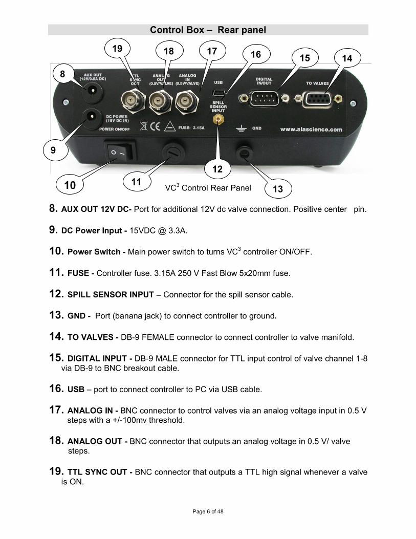
Control Box – Rear panel
VC3 Control Rear Panel
8. AUX OUT 12V DC- Port for additional 12V dc valve connection. Positive center pin.
9. DC Power Input - 15VDC @ 3.3A.
10. Power Switch - Main power switch to turns VC3 controller ON/OFF.
11. FUSE - Controller fuse. 3.15A 250 V Fast Blow 5x20mm fuse.
12. SPILL SENSOR INPUT – Connector for the spill sensor cable.
13. GND - Port (banana jack) to connect controller to ground.
14. TO VALVES - DB-9 FEMALE connector to connect controller to valve manifold.
15. DIGITAL INPUT - DB-9 MALE connector for TTL input control of valve channel 1-8
via DB-9 to BNC breakout cable.
16. USB – port to connect controller to PC via USB cable.
17. ANALOG IN - BNC connector to control valves via an analog voltage input in 0.5 V steps with a +/-100mv threshold.
18. ANALOG OUT - BNC connector that outputs an analog voltage in 0.5 V/ valve steps.
19. TTL SYNC OUT - BNC connector that outputs a TTL high signal whenever a valve
is ON.
14
13
8
10
9
11
15
12
19 18 17 16
Page 7 of 48
VC38 Controller Instructions
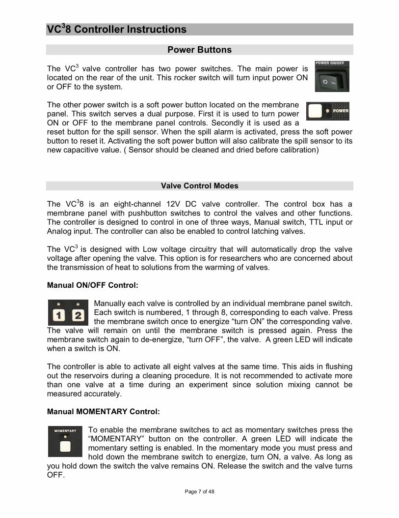
Power Buttons The VC3 valve controller has two power switches. The main power is located on the rear of the unit. This rocker switch will turn input power ON or OFF to the system. The other power switch is a soft power button located on the membrane panel. This switch serves a dual purpose. First it is used to turn power ON or OFF to the membrane panel controls. Secondly it is used as a reset button for the spill sensor. When the spill alarm is activated, press the soft power button to reset it. Activating the soft power button will also calibrate the spill sensor to its new capacitive value. ( Sensor should be cleaned and dried before calibration)
Valve Control Modes
The VC38 is an eight-channel 12V DC valve controller. The control box has a membrane panel with pushbutton switches to control the valves and other functions. The controller is designed to control in one of three ways, Manual switch, TTL input or Analog input. The controller can also be enabled to control latching valves. The VC3 is designed with Low voltage circuitry that will automatically drop the valve voltage after opening the valve. This option is for researchers who are concerned about the transmission of heat to solutions from the warming of valves. Manual ON/OFF Control:
Manually each valve is controlled by an individual membrane panel switch. Each switch is numbered, 1 through 8, corresponding to each valve. Press the membrane switch once to energize “turn ON” the corresponding valve.
The valve will remain on until the membrane switch is pressed again. Press the membrane switch again to de-energize, “turn OFF”, the valve. A green LED will indicate when a switch is ON. The controller is able to activate all eight valves at the same time. This aids in flushing out the reservoirs during a cleaning procedure. It is not recommended to activate more than one valve at a time during an experiment since solution mixing cannot be measured accurately. Manual MOMENTARY Control:
To enable the membrane switches to act as momentary switches press the “MOMENTARY” button on the controller. A green LED will indicate the momentary setting is enabled. In the momentary mode you must press and hold down the membrane switch to energize, turn ON, a valve. As long as
you hold down the switch the valve remains ON. Release the switch and the valve turns OFF.
Page 8 of 48
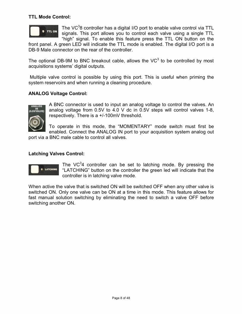
TTL Mode Control: The VC38 controller has a digital I/O port to enable valve control via TTL signals. This port allows you to control each valve using a single TTL “high” signal. To enable this feature press the TTL ON button on the
front panel. A green LED will indicate the TTL mode is enabled. The digital I/O port is a DB-9 Male connector on the rear of the controller. The optional DB-9M to BNC breakout cable, allows the VC3 to be controlled by most acquisitions systems’ digital outputs. Multiple valve control is possible by using this port. This is useful when priming the system reservoirs and when running a cleaning procedure. ANALOG Voltage Control:
A BNC connector is used to input an analog voltage to control the valves. An analog voltage from 0.5V to 4.0 V dc in 0.5V steps will control valves 1-8, respectively. There is a +/-100mV threshold. To operate in this mode, the “MOMENTARY” mode switch must first be enabled. Connect the ANALOG IN port to your acquisition system analog out
port via a BNC male cable to control all valves. Latching Valves Control:
The VC34 controller can be set to latching mode. By pressing the “LATCHING” button on the controller the green led will indicate that the controller is in latching valve mode.
When active the valve that is switched ON will be switched OFF when any other valve is switched ON. Only one valve can be ON at a time in this mode. This feature allows for fast manual solution switching by eliminating the need to switch a valve OFF before switching another ON.
Page 9 of 48
Rear Panel Connections
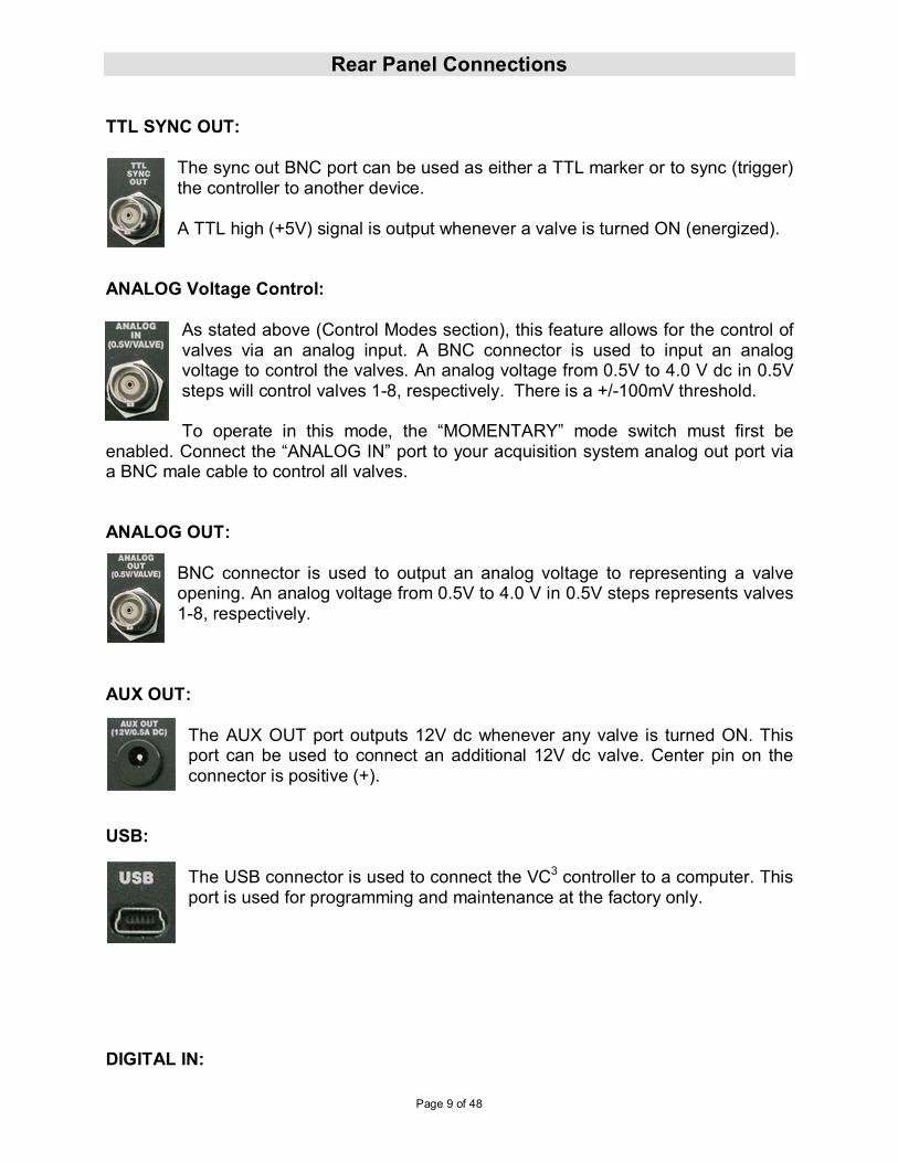
TTL SYNC OUT:
The sync out BNC port can be used as either a TTL marker or to sync (trigger) the controller to another device. A TTL high (+5V) signal is output whenever a valve is turned ON (energized).
ANALOG Voltage Control:
As stated above (Control Modes section), this feature allows for the control of valves via an analog input. A BNC connector is used to input an analog voltage to control the valves. An analog voltage from 0.5V to 4.0 V dc in 0.5V steps will control valves 1-8, respectively. There is a +/-100mV threshold. To operate in this mode, the “MOMENTARY” mode switch must first be
enabled. Connect the “ANALOG IN” port to your acquisition system analog out port via a BNC male cable to control all valves. ANALOG OUT:
BNC connector is used to output an analog voltage to representing a valve opening. An analog voltage from 0.5V to 4.0 V in 0.5V steps represents valves 1-8, respectively.
AUX OUT:
The AUX OUT port outputs 12V dc whenever any valve is turned ON. This port can be used to connect an additional 12V dc valve. Center pin on the connector is positive (+).
USB:
The USB connector is used to connect the VC3 controller to a computer. This port is used for programming and maintenance at the factory only.
DIGITAL IN:
Page 10 of 48
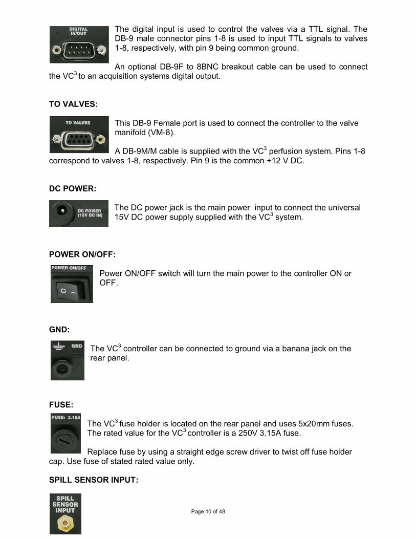
The digital input is used to control the valves via a TTL signal. The DB-9 male connector pins 1-8 is used to input TTL signals to valves 1-8, respectively, with pin 9 being common ground. An optional DB-9F to 8BNC breakout cable can be used to connect
the VC3 to an acquisition systems digital output. TO VALVES:
This DB-9 Female port is used to connect the controller to the valve manifold (VM-8). A DB-9M/M cable is supplied with the VC3 perfusion system. Pins 1-8
correspond to valves 1-8, respectively. Pin 9 is the common +12 V DC. DC POWER:
The DC power jack is the main power input to connect the universal 15V DC power supply supplied with the VC3 system.
POWER ON/OFF:
Power ON/OFF switch will turn the main power to the controller ON or OFF.
GND:
The VC3 controller can be connected to ground via a banana jack on the rear panel.
FUSE:
The VC3 fuse holder is located on the rear panel and uses 5x20mm fuses. The rated value for the VC3 controller is a 250V 3.15A fuse. Replace fuse by using a straight edge screw driver to twist off fuse holder
cap. Use fuse of stated rated value only. SPILL SENSOR INPUT:
Page 11 of 48
The VC3 has been designed with a built in spill sensor. This feature will allow for the protection against overflows from chamber or dishes onto expensive optics or electronics. To use this feature simply connect the spill sensor cable supplied with the VC3 system to this port. Place the sensor wire around the area you wish to protect from liquid spills and turn ON the controller The VC3 controller auto calibrates the spill sensor every time it is turned ON. Therefore, it is important that the spill sensor cable be connected before the controller is turned ON. If a spill occurs the sensor will detect it and two things will happen.
1) There will be a soft power shut down. This means power to the valves will be cut off. The main power will still be ON.
2) An audible and visual alarm will be activated. The audible alarm will be a chirping sound. The visual alarm is a red LED on the controller will blink repeatedly.
To reset the system after a spill
After a spill the alarm will sound and power will be cut to the valves. Follow the procedure below to reset the controller:
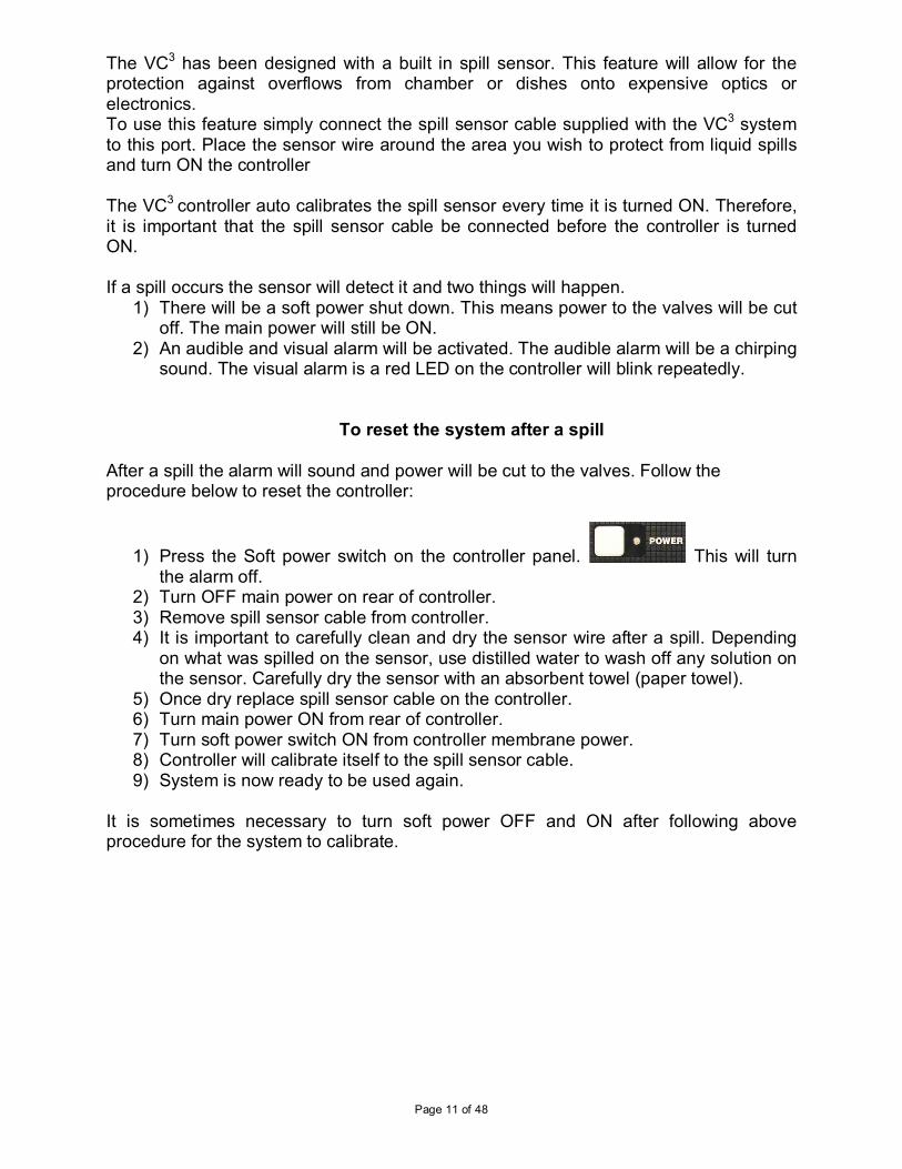
1) Press the Soft power switch on the controller panel. This will turn the alarm off.
2) Turn OFF main power on rear of controller. 3) Remove spill sensor cable from controller. 4) It is important to carefully clean and dry the sensor wire after a spill. Depending
on what was spilled on the sensor, use distilled water to wash off any solution on the sensor. Carefully dry the sensor with an absorbent towel (paper towel).
5) Once dry replace spill sensor cable on the controller. 6) Turn main power ON from rear of controller. 7) Turn soft power switch ON from controller membrane power. 8) Controller will calibrate itself to the spill sensor cable. 9) System is now ready to be used again.
It is sometimes necessary to turn soft power OFF and ON after following above procedure for the system to calibrate.
Page 12 of 48
VC38 Perfusion System Components Reservoir Bracket
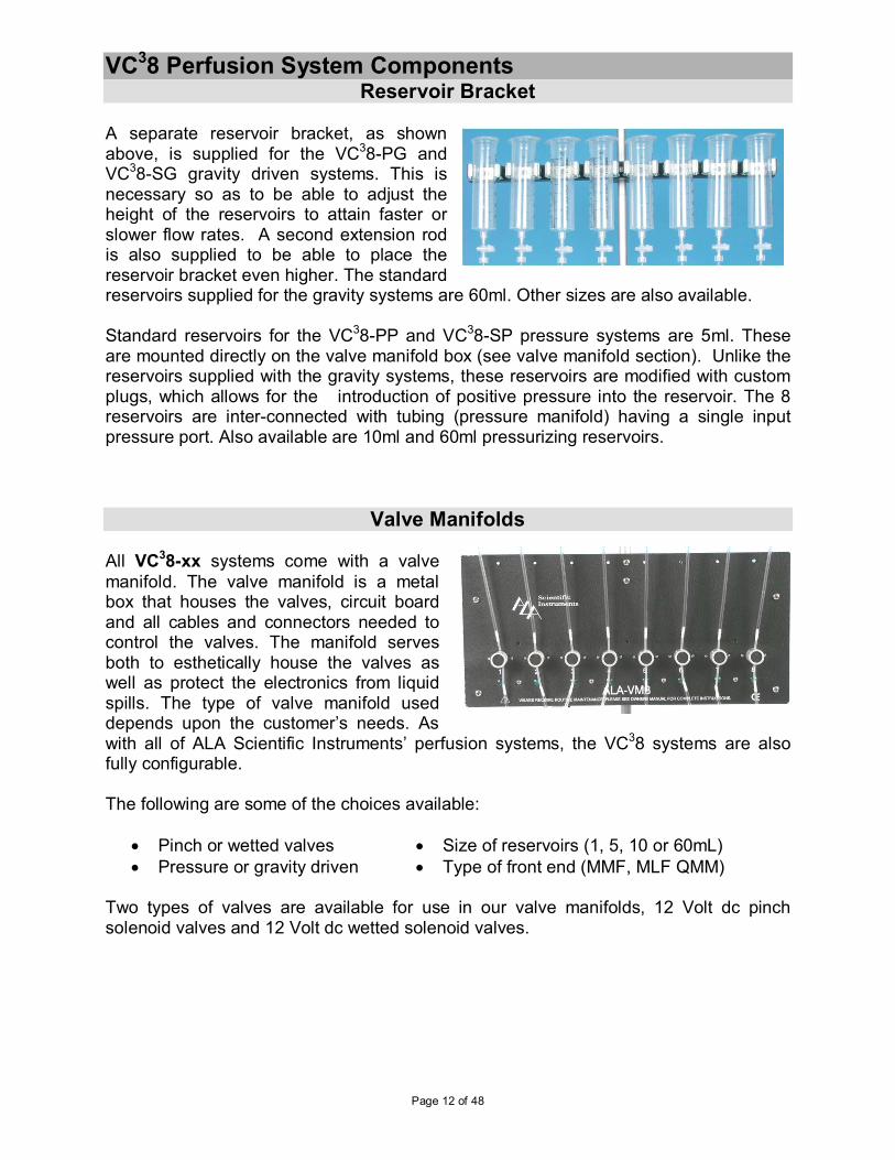
A separate reservoir bracket, as shown above, is supplied for the VC38-PG and VC38-SG gravity driven systems. This is necessary so as to be able to adjust the height of the reservoirs to attain faster or slower flow rates. A second extension rod is also supplied to be able to place the reservoir bracket even higher. The standard reservoirs supplied for the gravity systems are 60ml. Other sizes are also available. Standard reservoirs for the VC38-PP and VC38-SP pressure systems are 5ml. These are mounted directly on the valve manifold box (see valve manifold section). Unlike the reservoirs supplied with the gravity systems, these reservoirs are modified with custom plugs, which allows for the introduction of positive pressure into the reservoir. The 8 reservoirs are inter-connected with tubing (pressure manifold) having a single input pressure port. Also available are 10ml and 60ml pressurizing reservoirs.
Valve Manifolds All VC38-xx systems come with a valve
manifold. The valve manifold is a metal box that houses the valves, circuit board and all cables and connectors needed to control the valves. The manifold serves both to esthetically house the valves as well as protect the electronics from liquid spills. The type of valve manifold used depends upon the customer’s needs. As with all of ALA Scientific Instruments’ perfusion systems, the VC38 systems are also fully configurable. The following are some of the choices available:
• Pinch or wetted valves
• Pressure or gravity driven
• Size of reservoirs (1, 5, 10 or 60mL)
• Type of front end (MMF, MLF QMM) Two types of valves are available for use in our valve manifolds, 12 Volt dc pinch solenoid valves and 12 Volt dc wetted solenoid valves.
Page 13 of 48
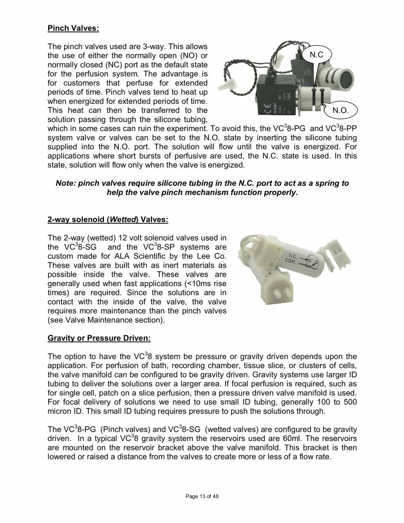
Pinch Valves: The pinch valves used are 3-way. This allows the use of either the normally open (NO) or normally closed (NC) port as the default state for the perfusion system. The advantage is for customers that perfuse for extended periods of time. Pinch valves tend to heat up when energized for extended periods of time. This heat can then be transferred to the solution passing through the silicone tubing, which in some cases can ruin the experiment. To avoid this, the VC38-PG and VC38-PP system valve or valves can be set to the N.O. state by inserting the silicone tubing supplied into the N.O. port. The solution will flow until the valve is energized. For applications where short bursts of perfusive are used, the N.C. state is used. In this state, solution will flow only when the valve is energized.
Note: pinch valves require silicone tubing in the N.C. port to act as a spring to help the valve pinch mechanism function properly.
2-way solenoid (Wetted) Valves:
The 2-way (wetted) 12 volt solenoid valves used in the VC38-SG and the VC38-SP systems are custom made for ALA Scientific by the Lee Co. These valves are built with as inert materials as possible inside the valve. These valves are generally used when fast applications (<10ms rise times) are required. Since the solutions are in contact with the inside of the valve, the valve requires more maintenance than the pinch valves (see Valve Maintenance section). Gravity or Pressure Driven: The option to have the VC38 system be pressure or gravity driven depends upon the application. For perfusion of bath, recording chamber, tissue slice, or clusters of cells, the valve manifold can be configured to be gravity driven. Gravity systems use larger ID tubing to deliver the solutions over a larger area. If focal perfusion is required, such as for single cell, patch on a slice perfusion, then a pressure driven valve manifold is used. For focal delivery of solutions we need to use small ID tubing, generally 100 to 500 micron ID. This small ID tubing requires pressure to push the solutions through. The VC38-PG (Pinch valves) and VC38-SG (wetted valves) are configured to be gravity driven. In a typical VC38 gravity system the reservoirs used are 60ml. The reservoirs are mounted on the reservoir bracket above the valve manifold. This bracket is then lowered or raised a distance from the valves to create more or less of a flow rate.
N.C
N.O.
Page 14 of 48
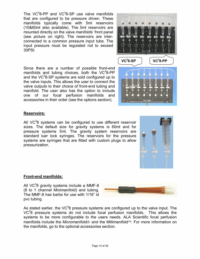
The VC38-PP and VC38-SP use valve manifolds that are configured to be pressure driven. These manifolds typically come with 5ml reservoirs (10&60ml also available). The 5ml reservoirs are mounted directly on the valve manifolds’ front panel (see picture on right). The reservoirs are inter-connected to a common pressure input tube. The input pressure must be regulated not to exceed 30PSI. Since there are a number of possible front-end manifolds and tubing choices, both the VC38-PP and the VC38-SP systems are sold configured up to the valve inputs. This allows the user to connect the valve outputs to their choice of front-end tubing and manifold. The user also has the option to include one of our focal perfusion manifolds and accessories in their order (see the options section). Reservoirs:
All VC38 systems can be configured to use different reservoir sizes. The default size for gravity systems is 60ml and for pressure systems 5ml. The gravity system reservoirs are standard luer lock syringes. The reservoirs for the pressure systems are syringes that are fitted with custom plugs to allow pressurization. Front-end manifolds: All VC38 gravity systems include a MMF-8 (8 to 1 channel Minimanifold) and tubing. The MMF-8 has barbs for use with 1/16” id pvc tubing. As stated earlier, the VC38 pressure systems are configured up to the valve input. The VC38 pressure systems do not include focal perfusion manifolds. This allows the systems to be more configurable to the users needs. ALA Scientific focal perfusion
manifolds include the Micromanifold and the Millimanifold. For more information on the manifolds, go to the optional accessories section.
VC38-PP VC38-SP

Page 15 of 48
DB-9M to BNC Breakout cable: The TTL valve control feature uses aDB-9Female connector as its input. To facilitate connection to the digital outputs of an acquisition system the DB9BNC8 cable can be used. (Optional)
Cable is color coded according to above image. Red corresponds to valve1, green to valve 2 and so forth. Connect the DB-9Female connector to the rear of the VC38 controller. Connect the BNC ‘s to the digital outputs of your acquisition system.
Page 16 of 48
Assembly Instructions
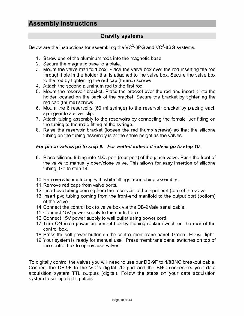
Gravity systems Below are the instructions for assembling the VC3-8PG and VC3-8SG systems.
1. Screw one of the aluminum rods into the magnetic base. 2. Secure the magnetic base to a plate. 3. Mount the valve manifold box. Place the valve box over the rod inserting the rod
through hole in the holder that is attached to the valve box. Secure the valve box to the rod by tightening the red cap (thumb) screws.
4. Attach the second aluminum rod to the first rod. 5. Mount the reservoir bracket. Place the bracket over the rod and insert it into the
holder located on the back of the bracket. Secure the bracket by tightening the red cap (thumb) screws.
6. Mount the 8 reservoirs (60 ml syringe) to the reservoir bracket by placing each syringe into a silver clip.
7. Attach tubing assembly to the reservoirs by connecting the female luer fitting on the tubing to the male fitting of the syringe.
8. Raise the reservoir bracket (loosen the red thumb screws) so that the silicone tubing on the tubing assembly is at the same height as the valves.
For pinch valves go to step 9. For wetted solenoid valves go to step 10. 9. Place silicone tubing into N.C. port (rear port) of the pinch valve. Push the front of
the valve to manually open/close valve. This allows for easy insertion of silicone tubing. Go to step 14.
10. Remove silicone tubing with white fittings from tubing assembly. 11. Remove red caps from valve ports. 12. Insert pvc tubing coming from the reservoir to the input port (top) of the valve. 13. Insert pvc tubing coming from the front-end manifold to the output port (bottom)
of the valve. 14. Connect the control box to valve box via the DB-9Male serial cable. 15. Connect 15V power supply to the control box 16. Connect 15V power supply to wall outlet using power cord. 17. Turn ON main power on control box by flipping rocker switch on the rear of the
control box. 18. Press the soft power button on the control membrane panel. Green LED will light. 19. Your system is ready for manual use. Press membrane panel switches on top of
the control box to open/close valves.
To digitally control the valves you will need to use our DB-9F to 4/8BNC breakout cable. Connect the DB-9F to the VC3’s digital I/O port and the BNC connectors your data acquisition system TTL outputs (digital). Follow the steps on your data acquisition system to set up digital pulses.
Page 17 of 48
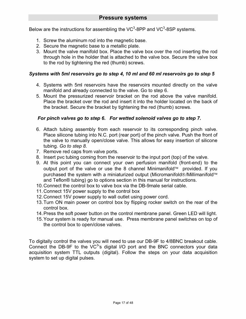
Pressure systems Below are the instructions for assembling the VC3-8PP and VC3-8SP systems.
1. Screw the aluminum rod into the magnetic base. 2. Secure the magnetic base to a metallic plate. 3. Mount the valve manifold box. Place the valve box over the rod inserting the rod
through hole in the holder that is attached to the valve box. Secure the valve box to the rod by tightening the red (thumb) screws.
Systems with 5ml reservoirs go to step 4, 10 ml and 60 ml reservoirs go to step 5
4. Systems with 5ml reservoirs have the reservoirs mounted directly on the valve manifold and already connected to the valve. Go to step 6.
5. Mount the pressurized reservoir bracket on the rod above the valve manifold. Place the bracket over the rod and insert it into the holder located on the back of the bracket. Secure the bracket by tightening the red (thumb) screws.
For pinch valves go to step 6. For wetted solenoid valves go to step 7. 6. Attach tubing assembly from each reservoir to its corresponding pinch valve.
Place silicone tubing into N.C. port (rear port) of the pinch valve. Push the front of the valve to manually open/close valve. This allows for easy insertion of silicone tubing. Go to step 8.
7. Remove red caps from valve ports. 8. Insert pvc tubing coming from the reservoir to the input port (top) of the valve. 9. At this point you can connect your own perfusion manifold (front-end) to the
output port of the valve or use the 8 channel Minimanifold provided. If you
purchased the system with a miniaturized output (Micromanifold/Millimanifold and Teflon® tubing) go to options section in this manual for instructions.
10. Connect the control box to valve box via the DB-9male serial cable. 11. Connect 15V power supply to the control box 12. Connect 15V power supply to wall outlet using power cord. 13. Turn ON main power on control box by flipping rocker switch on the rear of the
control box. 14. Press the soft power button on the control membrane panel. Green LED will light. 15. Your system is ready for manual use. Press membrane panel switches on top of
the control box to open/close valves.
To digitally control the valves you will need to use our DB-9F to 4/8BNC breakout cable. Connect the DB-9F to the VC3’s digital I/O port and the BNC connectors your data acquisition system TTL outputs (digital). Follow the steps on your data acquisition system to set up digital pulses.
Page 18 of 48
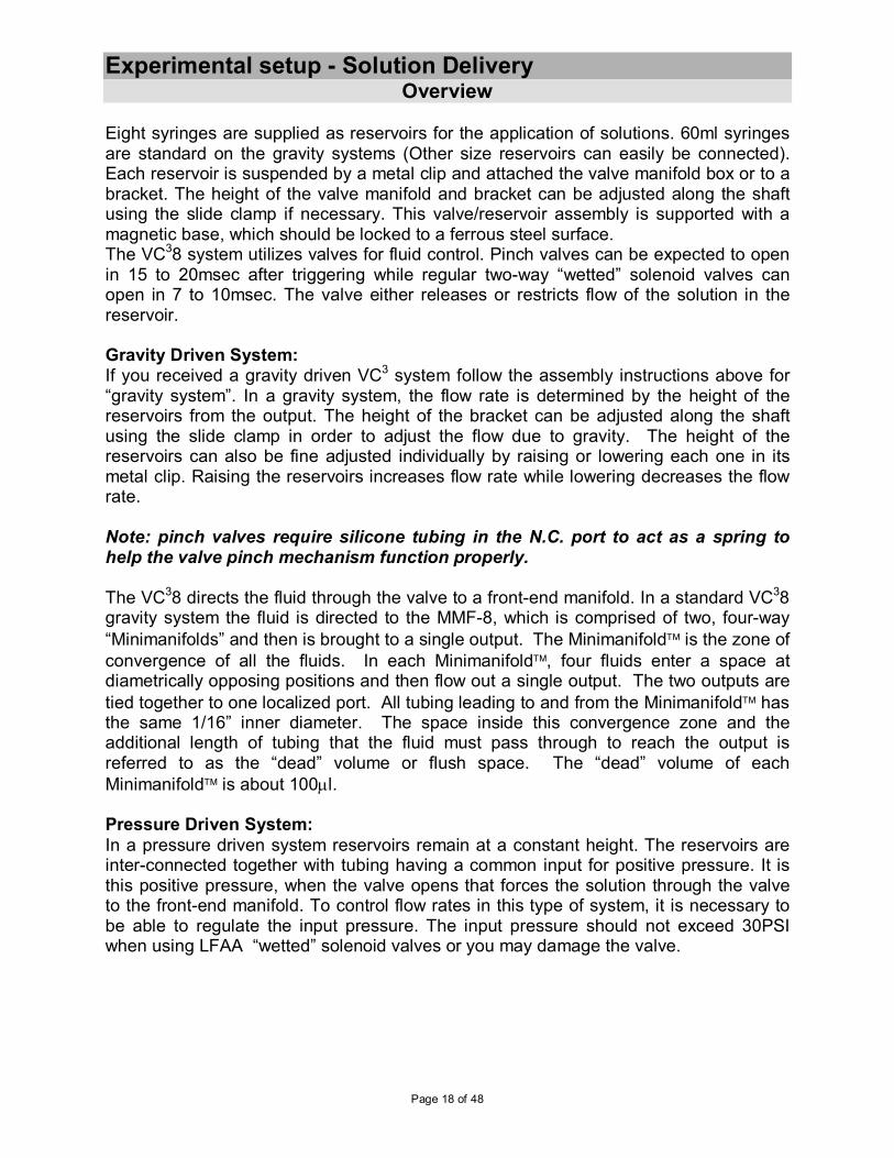
Experimental setup - Solution Delivery Overview
Eight syringes are supplied as reservoirs for the application of solutions. 60ml syringes are standard on the gravity systems (Other size reservoirs can easily be connected). Each reservoir is suspended by a metal clip and attached the valve manifold box or to a bracket. The height of the valve manifold and bracket can be adjusted along the shaft using the slide clamp if necessary. This valve/reservoir assembly is supported with a magnetic base, which should be locked to a ferrous steel surface. The VC38 system utilizes valves for fluid control. Pinch valves can be expected to open in 15 to 20msec after triggering while regular two-way “wetted” solenoid valves can open in 7 to 10msec. The valve either releases or restricts flow of the solution in the reservoir. Gravity Driven System: If you received a gravity driven VC3 system follow the assembly instructions above for “gravity system”. In a gravity system, the flow rate is determined by the height of the reservoirs from the output. The height of the bracket can be adjusted along the shaft using the slide clamp in order to adjust the flow due to gravity. The height of the reservoirs can also be fine adjusted individually by raising or lowering each one in its metal clip. Raising the reservoirs increases flow rate while lowering decreases the flow rate. Note: pinch valves require silicone tubing in the N.C. port to act as a spring to help the valve pinch mechanism function properly.
The VC38 directs the fluid through the valve to a front-end manifold. In a standard VC38 gravity system the fluid is directed to the MMF-8, which is comprised of two, four-way
“Minimanifolds” and then is brought to a single output. The Minimanifold is the zone of
convergence of all the fluids. In each Minimanifold, four fluids enter a space at diametrically opposing positions and then flow out a single output. The two outputs are
tied together to one localized port. All tubing leading to and from the Minimanifold has the same 1/16” inner diameter. The space inside this convergence zone and the additional length of tubing that the fluid must pass through to reach the output is referred to as the “dead” volume or flush space. The “dead” volume of each
Minimanifold is about 100µl. Pressure Driven System:
In a pressure driven system reservoirs remain at a constant height. The reservoirs are inter-connected together with tubing having a common input for positive pressure. It is this positive pressure, when the valve opens that forces the solution through the valve to the front-end manifold. To control flow rates in this type of system, it is necessary to be able to regulate the input pressure. The input pressure should not exceed 30PSI when using LFAA “wetted” solenoid valves or you may damage the valve.

Page 19 of 48
Daily Usage
Getting the VC3 ready for an experiment
Whether you system is gravity or pressure driven the priming procedure is basically the same for both. Both systems as stated previously are comprised of 8 reservoirs and 8 valves and the tubing connecting them. When preparing to prime the system the, start by powering up the VC3 controller. For a pressure driven system, make certain that your source of positive pressure is working and hooked up to the valve manifold. Once your system is fully assembled and you are ready to start perfusion do a final check. First make sure that the valve manifold is close enough to your setup to allow the front-end manifold to reach. Second, it is a good idea to ground the VC38 system to your set-up ground. The grounding connector (banana jack) on the rear of the control box can be used to secure a wire between the VC38 and your set-up ground.
Filling the Reservoirs
Fill each reservoir by using a syringe with a luer-lock tip. Lock the filling syringe onto the luer stop-cock of the particular reservoir that you want to fill. Twist the filling syringe to lock it in place. Move the lever on the stop-cock down, depress the syringe and fill the reservoir. Do not fill it to the air input port, leave a little space. When the reservoir is filled, return the lever of the stop-cock to horizontal and remove the syringe. Never try to fill a reservoir when the valve is open and pressure is being applied! Move onto the next solution and continue until they are all filled.
Important notes: All tubes must be filled for the unit to operate properly. This means that all reservoirs must be filled and each tube primed and free of air bubbles. Tubes not being utilized can be filled with distilled water.
When filling the the resevoirs it is best to use solutions that have been de-gassed. Warm the solutions to a few degrees above room temperature or above the temperature at which they will be applied. Solutions that are not de-gassed run the risk of releasing air bubbles during the experiment as they pass through the small tubes. Solutions should always be filtered before being added to the system. For pressure systems, check that at least 4 psi (~200mm/Hg) has been set as the pressure for each reservoir (This is the minimum pressure needed for priming the system, more pressure may be desirable.).
Page 20 of 48
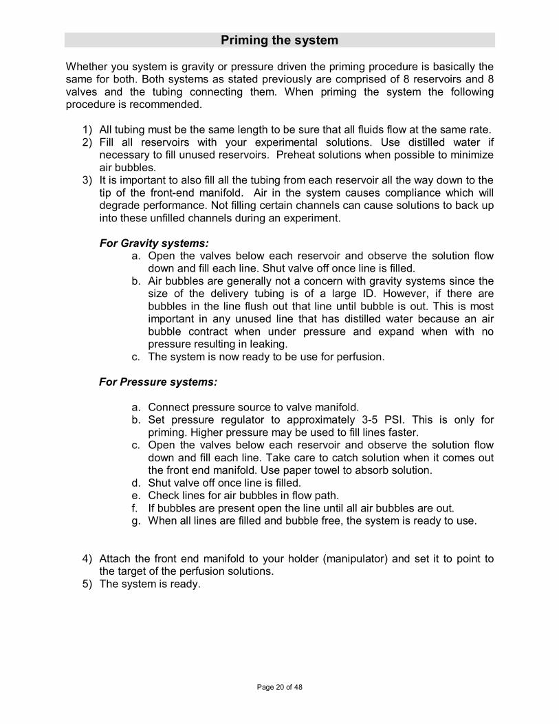
Priming the system Whether you system is gravity or pressure driven the priming procedure is basically the same for both. Both systems as stated previously are comprised of 8 reservoirs and 8 valves and the tubing connecting them. When priming the system the following procedure is recommended.
1) All tubing must be the same length to be sure that all fluids flow at the same rate. 2) Fill all reservoirs with your experimental solutions. Use distilled water if
necessary to fill unused reservoirs. Preheat solutions when possible to minimize air bubbles.
3) It is important to also fill all the tubing from each reservoir all the way down to the tip of the front-end manifold. Air in the system causes compliance which will degrade performance. Not filling certain channels can cause solutions to back up into these unfilled channels during an experiment. For Gravity systems:
a. Open the valves below each reservoir and observe the solution flow down and fill each line. Shut valve off once line is filled.
b. Air bubbles are generally not a concern with gravity systems since the size of the delivery tubing is of a large ID. However, if there are bubbles in the line flush out that line until bubble is out. This is most important in any unused line that has distilled water because an air bubble contract when under pressure and expand when with no pressure resulting in leaking.
c. The system is now ready to be use for perfusion.
For Pressure systems:
a. Connect pressure source to valve manifold. b. Set pressure regulator to approximately 3-5 PSI. This is only for
priming. Higher pressure may be used to fill lines faster. c. Open the valves below each reservoir and observe the solution flow
down and fill each line. Take care to catch solution when it comes out the front end manifold. Use paper towel to absorb solution.
d. Shut valve off once line is filled. e. Check lines for air bubbles in flow path. f. If bubbles are present open the line until all air bubbles are out. g. When all lines are filled and bubble free, the system is ready to use.
4) Attach the front end manifold to your holder (manipulator) and set it to point to the target of the perfusion solutions.
5) The system is ready.

Page 21 of 48
Running the VC3 perfusion system Depending on which mode of valve control you chose to use, solutions will be delivered to the target whenever a valve is energized. By pressing any of the valve switches on the membrane panel (1-8) solution can be delivered to your target and stopped again manually. TTL and analog voltage protocols can be written in your acquisition system software for automated valve control. It is very important that maintenance is performed on all parts that are exposed to solutions. Flush out entire system when experiment is done (see Maintenance section). When using focal front-ends that have µm ID openings, proper cleaning will increase life span and minimize clogging.
Page 22 of 48
VC3 Software Software Installation
The VC3 perfusion system can be controlled manually, by an analog signal, TTL signal or via the USB port from a PC. To control the VC3 via software you must first install the VC3 program provided with the system on a CD. The following steps should be followed:
1. Place the VC3 CD supplied into the PC CD/DVD player.
2. Go to the ‘My Computer’ and open the CD/DVD device. The VC3 files will be
displayed. Select the operating system folder for your PC.
3. Run the Setup.exe file to load the VC3 program. Follow the instructions provided.
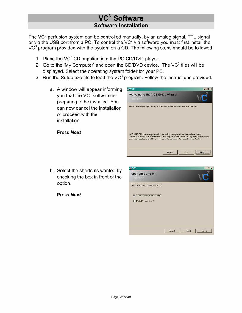
a. A window will appear informing
you that the VC3 software is
preparing to be installed. You
can now cancel the installation
or proceed with the
installation.
Press Next
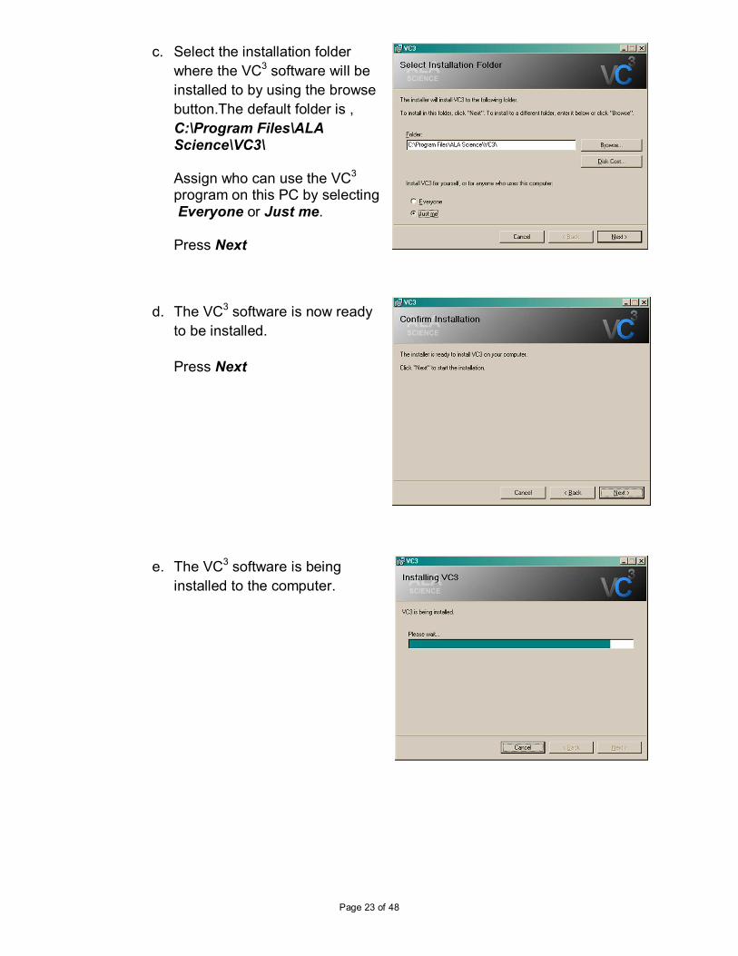
b. Select the shortcuts wanted by
checking the box in front of the
option.
Press Next
Page 23 of 48
c. Select the installation folder
where the VC3 software will be
installed to by using the browse
button.The default folder is ,
C:\Program Files\ALA Science\VC3\ Assign who can use the VC3 program on this PC by selecting Everyone or Just me. Press Next
d. The VC3 software is now ready
to be installed.
Press Next
e. The VC3 software is being
installed to the computer.
Page 24 of 48
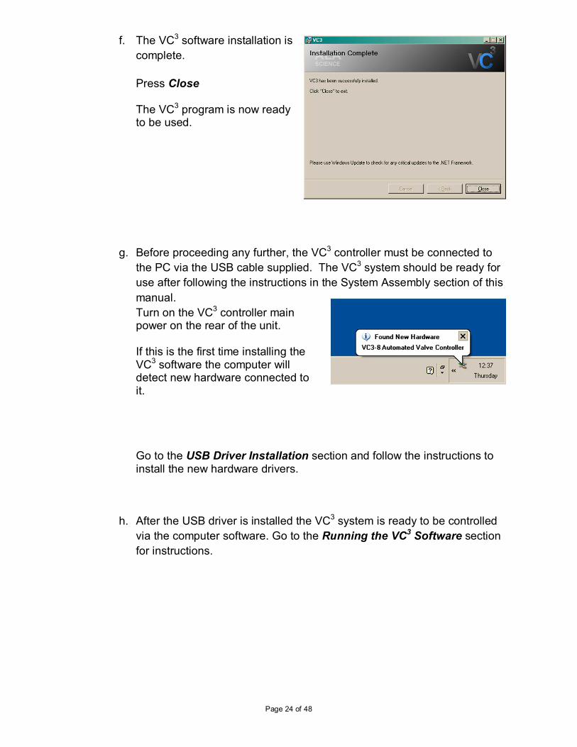
f. The VC3 software installation is
complete.
Press Close The VC3 program is now ready to be used.
g. Before proceeding any further, the VC3 controller must be connected to
the PC via the USB cable supplied. The VC3 system should be ready for
use after following the instructions in the System Assembly section of this
manual.
Turn on the VC3 controller main power on the rear of the unit. If this is the first time installing the VC3 software the computer will detect new hardware connected to it.
Go to the USB Driver Installation section and follow the instructions to install the new hardware drivers.
h. After the USB driver is installed the VC3 system is ready to be controlled
via the computer software. Go to the Running the VC3 Software section
for instructions.
Page 25 of 48
VC3 USB Driver Installation
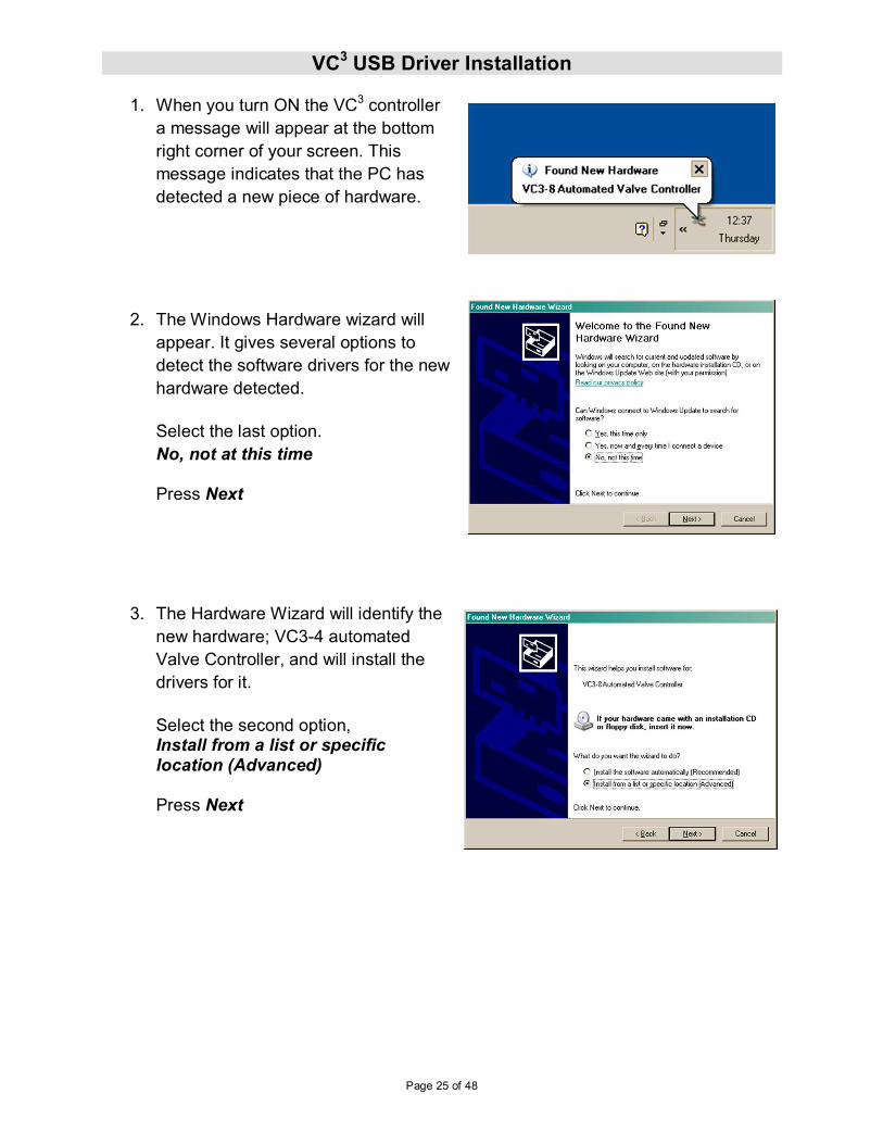
1. When you turn ON the VC3 controller
a message will appear at the bottom
right corner of your screen. This
message indicates that the PC has
detected a new piece of hardware.
2. The Windows Hardware wizard will
appear. It gives several options to
detect the software drivers for the new
hardware detected.
Select the last option.
No, not at this time Press Next
3. The Hardware Wizard will identify the
new hardware; VC3-4 automated
Valve Controller, and will install the
drivers for it.
Select the second option, Install from a list or specific location (Advanced) Press Next
Page 26 of 48
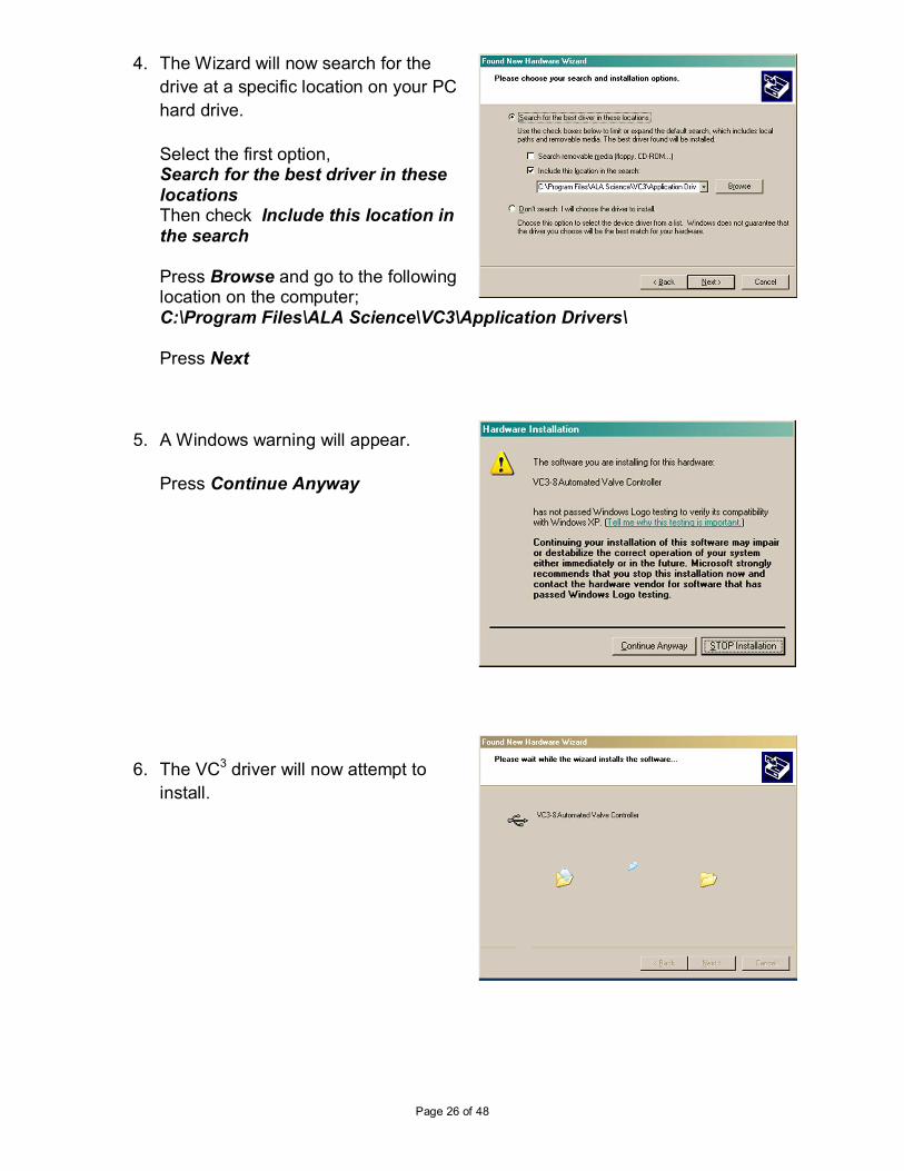
4. The Wizard will now search for the
drive at a specific location on your PC
hard drive.
Select the first option, Search for the best driver in these locations Then check Include this location in the search Press Browse and go to the following location on the computer; C:\Program Files\ALA Science\VC3\Application Drivers\ Press Next
5. A Windows warning will appear.
Press Continue Anyway
6. The VC3 driver will now attempt to
install.
Page 27 of 48
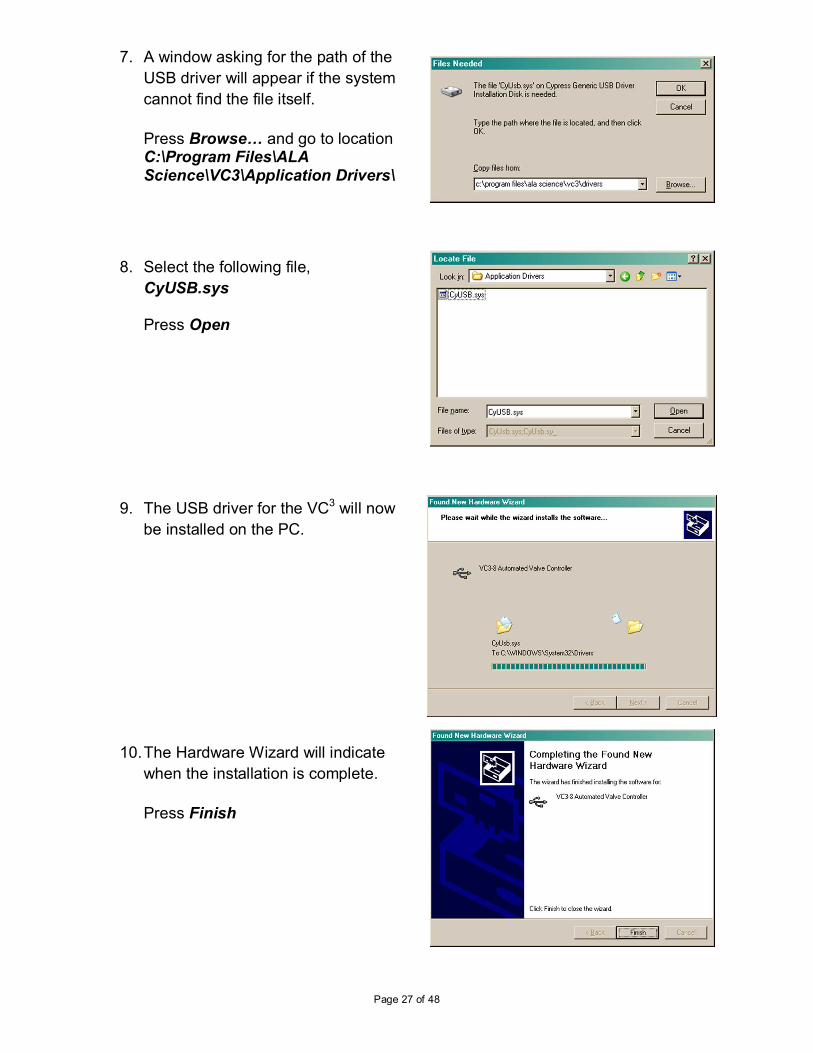
7. A window asking for the path of the
USB driver will appear if the system
cannot find the file itself.
Press Browse8 and go to location C:\Program Files\ALA Science\VC3\Application Drivers\
8. Select the following file,
CyUSB.sys Press Open
9. The USB driver for the VC3 will now
be installed on the PC.
10. The Hardware Wizard will indicate
when the installation is complete.
Press Finish
Page 28 of 48
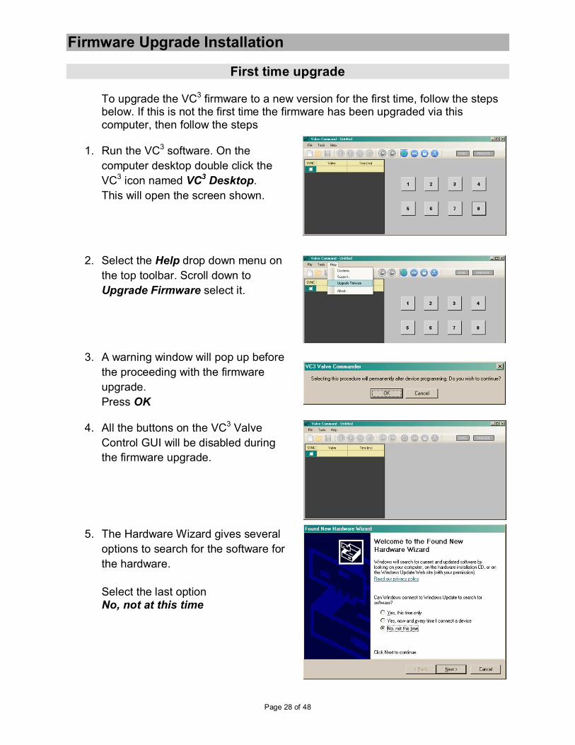
Firmware Upgrade Installation
First time upgrade
To upgrade the VC3 firmware to a new version for the first time, follow the steps below. If this is not the first time the firmware has been upgraded via this computer, then follow the steps
1. Run the VC3 software. On the
computer desktop double click the
VC3 icon named VC3 Desktop.
This will open the screen shown.
2. Select the Help drop down menu on
the top toolbar. Scroll down to
Upgrade Firmware select it.
3. A warning window will pop up before
the proceeding with the firmware
upgrade.
Press OK
4. All the buttons on the VC3 Valve
Control GUI will be disabled during
the firmware upgrade.
5. The Hardware Wizard gives several
options to search for the software for
the hardware.
Select the last option No, not at this time

Page 29 of 48
6. The Hardware Wizard identifies the
hardware and gives options to install
the firmware. Select the second
option,
Install from a list or specific location
7. Select Search for the best driver in
these locations option. Check
include this location in the search.
Browse to C:\Program Files\ALA Science\VC3\Firmware Upgrade Tools\USB Driver\ for the files required.
8. Since this is the first time this
computer will upgrade the VC3
firmware, it must install the driver that
will communiate with the VC3
processor. The USB Bootloader
driver is loaded to the computer. This
will allow for future firmware updates.
9. A Windows warning about the
software being installed will appear.
Press Continue Anyway
Page 30 of 48
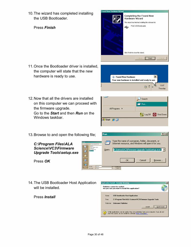
10. The wizard has completed installing
the USB Bootloader.
Press Finish
11. Once the Bootloader driver is installed,
the computer will state that the new
hardware is ready to use.
12. Now that all the drivers are installed
on this computer we can proceed with
the firmware upgrade.
Go to the Start and then Run on the Windows taskbar.
13. Browse to and open the following file;
C:\Program Files\ALA Science\VC3\Firmware Upgrade Tools\setup.exe Press OK
14. The USB Bootloader Host Application
will be installed.
Press Install
Page 31 of 48
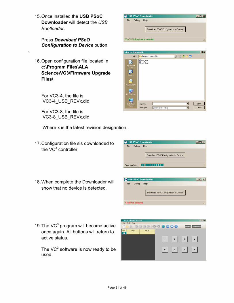
15. Once installed the USB PSoC
Downloader will detect the USB
Bootloader.
Press Download PScO Configuration to Device button.
.
16. Open configuration file located in
c:\Program Files\ALA
Science\VC3\Firmware Upgrade
Files\
For VC3-4, the file is VC3-4_USB_REVx.dld For VC3-8, the file is VC3-8_USB_REVx.dld Where x is the latest revision desigantion.
17. Configuration file sis downloaded to
the VC3 controller.
18. When complete the Downloader will
show that no device is detected.
19. The VC3 program will become active
once again. All buttons will return to
active status.
The VC3 software is now ready to be used.

Page 32 of 48
Firmware Upgrade – not first time If you previously upgraded the firmware of the VC3 on this computer, then all the drivers and software required to perform the upgrade are already installed. Follow the steps below to upgrade the firmware.
1. Run the VC3 software. On the
computer desktop double click the
VC3 icon named VC3 Desktop.
This will open the screen shown.
2. Select the Help drop down menu on
the top toolbar. Scroll down to
Upgrade Firmware select it.
3. A warning window will pop up before
the proceeding with the firmware
upgrade.
Press OK
4. All the buttons on the VC3 Valve
Control GUI will be disabled during
the firmware upgrade.
5. Go to Start and then All Programs
on the Windows taskbar. Find the
Cypress Microsystems tag and then
click on the USB Bootloader Host
Application.
Page 33 of 48
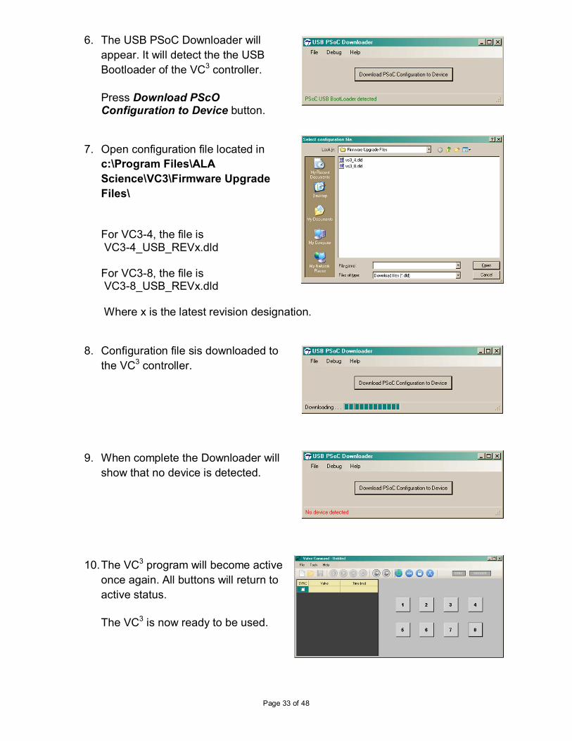
6. The USB PSoC Downloader will
appear. It will detect the the USB
Bootloader of the VC3 controller.
Press Download PScO Configuration to Device button.
7. Open configuration file located in
c:\Program Files\ALA
Science\VC3\Firmware Upgrade
Files\
For VC3-4, the file is VC3-4_USB_REVx.dld For VC3-8, the file is VC3-8_USB_REVx.dld Where x is the latest revision designation.
8. Configuration file sis downloaded to
the VC3 controller.
9. When complete the Downloader will
show that no device is detected.
10. The VC3 program will become active
once again. All buttons will return to
active status.
The VC3 is now ready to be used.
Page 34 of 48
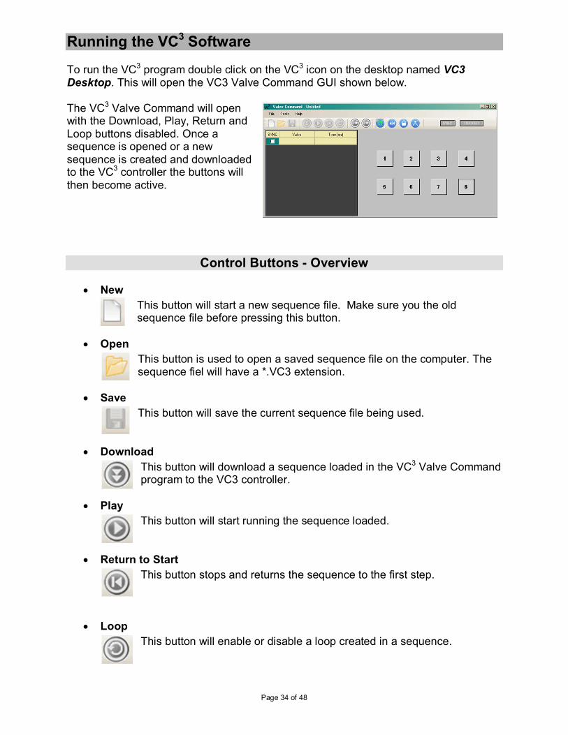
Running the VC3 Software To run the VC3 program double click on the VC3 icon on the desktop named VC3 Desktop. This will open the VC3 Valve Command GUI shown below.
The VC3 Valve Command will open with the Download, Play, Return and Loop buttons disabled. Once a sequence is opened or a new sequence is created and downloaded to the VC3 controller the buttons will then become active.
Control Buttons - Overview
• New
This button will start a new sequence file. Make sure you the old sequence file before pressing this button.
• Open
This button is used to open a saved sequence file on the computer. The sequence fiel will have a *.VC3 extension.
• Save
This button will save the current sequence file being used.
• Download
This button will download a sequence loaded in the VC3 Valve Command program to the VC3 controller.
• Play
This button will start running the sequence loaded.
• Return to Start
This button stops and returns the sequence to the first step.
• Loop
This button will enable or disable a loop created in a sequence.
Page 35 of 48
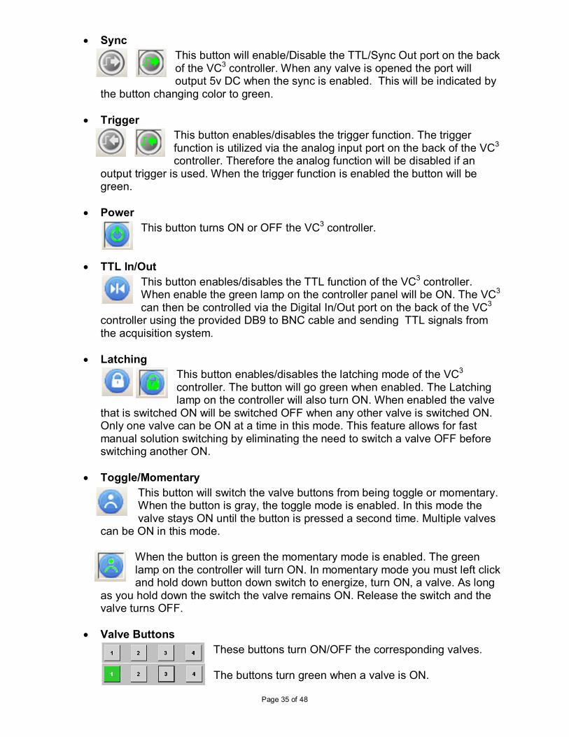
• Sync
This button will enable/Disable the TTL/Sync Out port on the back of the VC3 controller. When any valve is opened the port will output 5v DC when the sync is enabled. This will be indicated by
the button changing color to green.
• Trigger
This button enables/disables the trigger function. The trigger function is utilized via the analog input port on the back of the VC3 controller. Therefore the analog function will be disabled if an
output trigger is used. When the trigger function is enabled the button will be green.
• Power
This button turns ON or OFF the VC3 controller.
• TTL In/Out
This button enables/disables the TTL function of the VC3 controller. When enable the green lamp on the controller panel will be ON. The VC3 can then be controlled via the Digital In/Out port on the back of the VC3
controller using the provided DB9 to BNC cable and sending TTL signals from the acquisition system.
• Latching
This button enables/disables the latching mode of the VC3 controller. The button will go green when enabled. The Latching lamp on the controller will also turn ON. When enabled the valve
that is switched ON will be switched OFF when any other valve is switched ON. Only one valve can be ON at a time in this mode. This feature allows for fast manual solution switching by eliminating the need to switch a valve OFF before switching another ON.
• Toggle/Momentary
This button will switch the valve buttons from being toggle or momentary. When the button is gray, the toggle mode is enabled. In this mode the valve stays ON until the button is pressed a second time. Multiple valves
can be ON in this mode.
When the button is green the momentary mode is enabled. The green lamp on the controller will turn ON. In momentary mode you must left click and hold down button down switch to energize, turn ON, a valve. As long
as you hold down the switch the valve remains ON. Release the switch and the valve turns OFF.
• Valve Buttons
These buttons turn ON/OFF the corresponding valves.
The buttons turn green when a valve is ON.
Page 36 of 48
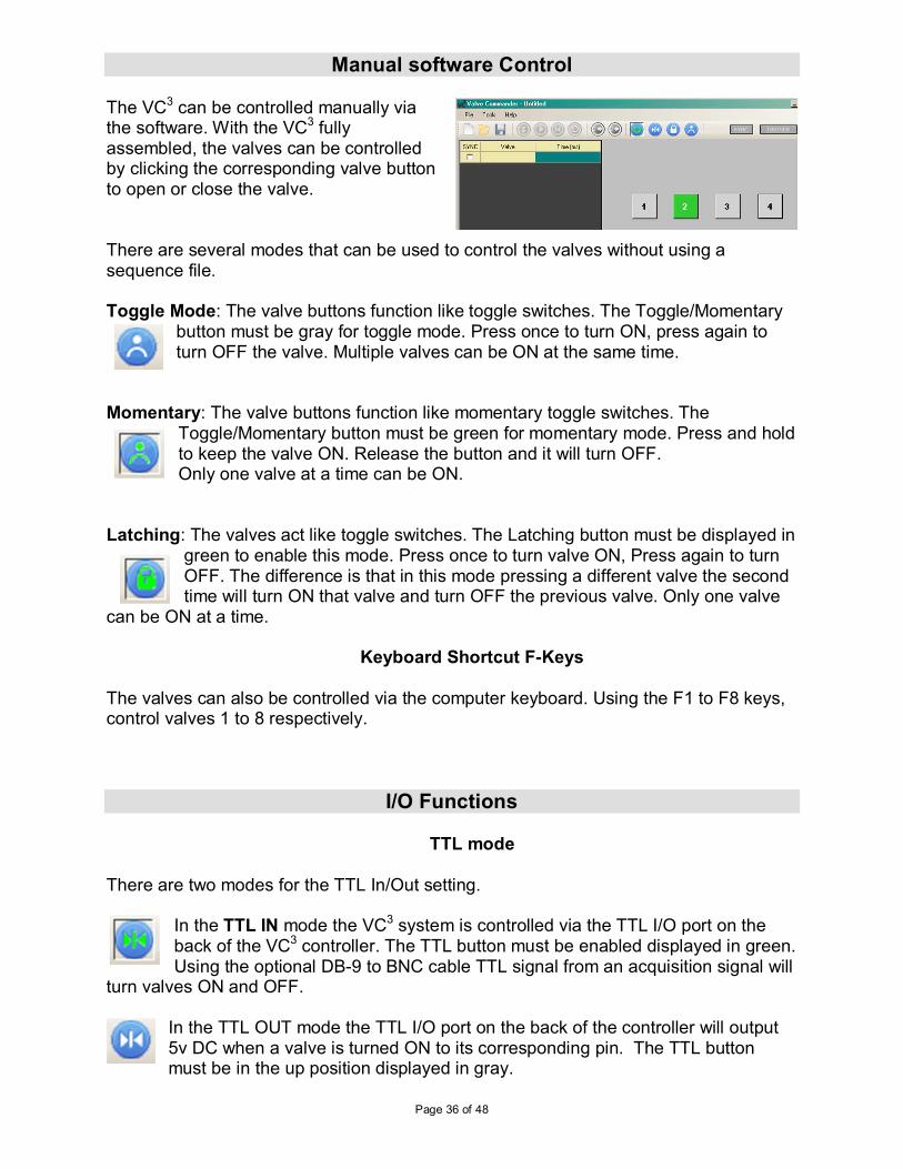
Manual software Control The VC3 can be controlled manually via the software. With the VC3 fully assembled, the valves can be controlled by clicking the corresponding valve button to open or close the valve. There are several modes that can be used to control the valves without using a sequence file. Toggle Mode: The valve buttons function like toggle switches. The Toggle/Momentary
button must be gray for toggle mode. Press once to turn ON, press again to turn OFF the valve. Multiple valves can be ON at the same time.
Momentary: The valve buttons function like momentary toggle switches. The
Toggle/Momentary button must be green for momentary mode. Press and hold to keep the valve ON. Release the button and it will turn OFF. Only one valve at a time can be ON.
Latching: The valves act like toggle switches. The Latching button must be displayed in
green to enable this mode. Press once to turn valve ON, Press again to turn OFF. The difference is that in this mode pressing a different valve the second time will turn ON that valve and turn OFF the previous valve. Only one valve
can be ON at a time.
Keyboard Shortcut F-Keys The valves can also be controlled via the computer keyboard. Using the F1 to F8 keys, control valves 1 to 8 respectively.
I/O Functions
TTL mode There are two modes for the TTL In/Out setting.
In the TTL IN mode the VC3 system is controlled via the TTL I/O port on the back of the VC3 controller. The TTL button must be enabled displayed in green. Using the optional DB-9 to BNC cable TTL signal from an acquisition signal will
turn valves ON and OFF.
In the TTL OUT mode the TTL I/O port on the back of the controller will output 5v DC when a valve is turned ON to its corresponding pin. The TTL button must be in the up position displayed in gray.

Page 37 of 48

Page 38 of 48
Working with a Sequence
Load a Sequence There are two ways to load a sequence on the VC3 software.
1. The first is to manually insert each step into the sequence. This is done by filling in the cells under Valve and Time appropriately. The valve number to be turned ON is written into the cell below the Valve column. The time the valve is to remain ON is written
into the cell below the Time column. The default time units is in millisecond(ms). The time units can be changed by placing the cursor on theTime label and left clicking. The units available are ms, s, MM:SS , HH:MM:SS
2. The second is to load a saved sequence file from the computer by pressing the Open button. Navigate to the folder where the saves sequence files are stored and open one. The default folder for saved sequence sample files is c:\Program Files\ALA Science\VC3\Examples\ . The loaded sequence must be downloaded to the VC3 controller by pressing the Download button.
Run a Sequence
Once a sequence is loaded and downloaded, the sequence can be executed. Press the Play button to start the sequence. The Start button will change into a Pause button. The sequence can be paused at any time while the sequence is running. Press the Play button again to continue running the sequence.
Page 39 of 48
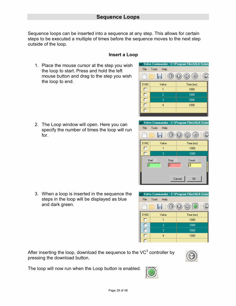
Sequence Loops Sequence loops can be inserted into a sequence at any step. This allows for certain steps to be executed a multiple of times before the sequence moves to the next step outside of the loop.
Insert a Loop
1. Place the mouse cursor at the step you wish
the loop to start. Press and hold the left mouse button and drag to the step you wish the loop to end.
2. The Loop window will open. Here you can
specify the number of times the loop will run for.
3. When a loop is inserted in the sequence the steps in the loop will be displayed as blue and dark green.
After inserting the loop, download the sequence to the VC3 controller by pressing the download button. The loop will now run when the Loop button is enabled.

Page 40 of 48
Remove a Loop To remove a loop function, place the cursor on the steps in the loop and right click with the mouse. This will bring up a window asking to remove the loop. Press OK to remove the loop. Press Cancel to leave the loop as is.
Page 41 of 48
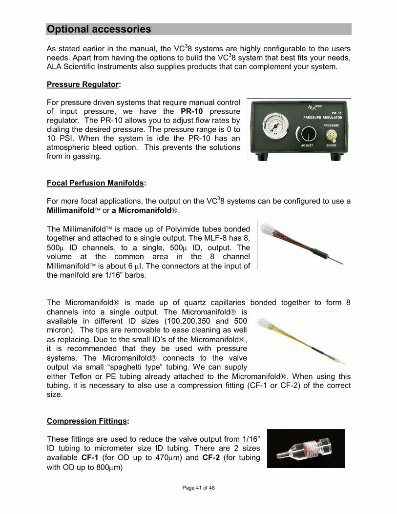
Optional accessories As stated earlier in the manual, the VC38 systems are highly configurable to the users needs. Apart from having the options to build the VC38 system that best fits your needs, ALA Scientific Instruments also supplies products that can complement your system. Pressure Regulator: For pressure driven systems that require manual control of input pressure, we have the PR-10 pressure regulator. The PR-10 allows you to adjust flow rates by dialing the desired pressure. The pressure range is 0 to 10 PSI. When the system is idle the PR-10 has an atmospheric bleed option. This prevents the solutions from in gassing. Focal Perfusion Manifolds: For more focal applications, the output on the VC38 systems can be configured to use a
Millimanifold or a Micromanifold.
The Millimanifold is made up of Polyimide tubes bonded together and attached to a single output. The MLF-8 has 8,
500µ ID channels, to a single, 500µ ID, output. The volume at the common area in the 8 channel
Millimanifold is about 6 µl. The connectors at the input of the manifold are 1/16” barbs.
The Micromanifold is made up of quartz capillaries bonded together to form 8
channels into a single output. The Micromanifold is available in different ID sizes (100,200,350 and 500 micron). The tips are removable to ease cleaning as well
as replacing. Due to the small ID’s of the Micromanifold, it is recommended that they be used with pressure
systems. The Micromanifold connects to the valve output via small “spaghetti type” tubing. We can supply
either Teflon or PE tubing already attached to the Micromanifold. When using this tubing, it is necessary to also use a compression fitting (CF-1 or CF-2) of the correct size. Compression Fittings:
These fittings are used to reduce the valve output from 1/16” ID tubing to micrometer size ID tubing. There are 2 sizes
available CF-1 (for OD up to 470µm) and CF-2 (for tubing
with OD up to 800µm)

Page 42 of 48
Teflon/Polyethylene Tubing: There are a variety of sizes of tubing that can used to connect the perfusion front-end and the valve. The tubing we use is Teflon or PE. There are 2 sizes that are available that will mate up with the compression fittings we supply. For Teflon it is FEP-1 and FEP-2 and for Polyethylene it is PE-10 and PE-20.
VC38 System Maintenance The VC38 does not require any regular maintenance other than routine flushing of the valve/tubing system to prevent microbial growth. All VC38 parts can be externally cleaned with a damp cloth and mild soap or alcohol and water. The system can be cleaned internally with any disinfectant. Flush system thoroughly with water after doing so. Strong Clorox solutions are not recommended and no CFCs, acetone or high-grade alcohols are to be used.
Spill Sensor
The spill sensor is a capacitive element that when wet causes the controller to sound an audible alarm and shuts off power to the valves. If the sensor wire gets wet, it must be completely dry before it can be used in the system again. To dry the sensor wire, use an absorbent towel (paper towel) to carefully remove all liquid from the wire. The system will calibrate itself to the new humidity level of its environment when it is reset. Therefore it is very important that the wire be as dry as possible so it functions properly when a spill occurs.
Maintenance of Pinch Solenoid Valves The silicone tubes that are supplied with the pinch valves will wear out after a while and lose their elasticity. If you notice degradation in flow, these should be replaced. It is important to replace the silicone tubing with the correct size. A trick you can use to prolong the life of the silicone tubing is just to move the tubing slightly up or down in the valve so that a fresh area of tubing is compressed in the valve. Replace tubing from your supplier or use 1.02mm ID, 2.16mm OD Pt cured medium density Silicone tubing. Other tubing is 1.6mm ID PVC or Tygon tubing.
Maintenance of LFAA “wetted” Solenoid Valves
The solenoid valves made by the Lee Company can fail. Either they will not open, or not close completely if dirt or gummy materials collect inside the valve. These materials can be introduced into the valve by the fluid that is flowing through it, or by bacteria and fungi that can grow in a valve that is not well cleaned. Particulate and gummy material have been found to damage the valve in two ways, one is where the armature of the valve passes through the solenoid, and the other is where the plunger impacts against the internal side of the output port at the “Normally Closed” side. Particulate and gummy materials can cause the armature to stick to the inside of

Page 43 of 48
the solenoid. This will either cause the valve not to open or not to close. Particulate and gummy materials can also stick to the plunger in the valve and cause it not to seal when the valve is closed and thus the valve will leak. Diagnosing the problem: In systems where small tubes are used it is possible to mistake the expansion of dissolved gasses in the liquid being used as a leak. Quite simply as the gasses come out of solution, they displace the liquid in the tubes and the system will appear to have a leak. This is especially common in pressure driven systems where many tubes come together to one output. The user must be certain that fluid leaving the system when it is not supposed to is indeed a leak from a valve. The first test to be performed is to determine which valve in the system is the leaky valve. The best way to do that is to remove the output tubes from the valve and apply liquid with mild pressure to the input of the valve. (See Diagrams below) If, under mild pressure, liquid emerges from the valve, then the valve is not seating. Be careful not to use too much pressure since that can cause the valve to seal and mask the problem. Once you have isolated the affected valve, follow the procedure below to clean it. If, after following the procedures outlined, you cannot return the valve to function, you should contact your representative or the factory. Special warranty restrictions apply to valves. Should the research substances you are using prove to consistently foul the Lee solenoid valve, please check with ALA about the possibility of switching some or all of your valves to pinch valves that can be cleaned by simply changing the tubing that passes through them. Please note that the Lee solenoid valves were selected after numerous tests of virtually every similar valve available. The Lee valve proved to be the fastest and to produce the smallest shock pulse upon opening and closing. The valves provided are amongst the most inert ones fabricated by Lee, specially for ALA Scientific based on ALA Scientifics’ own specifications.
Page 44 of 48
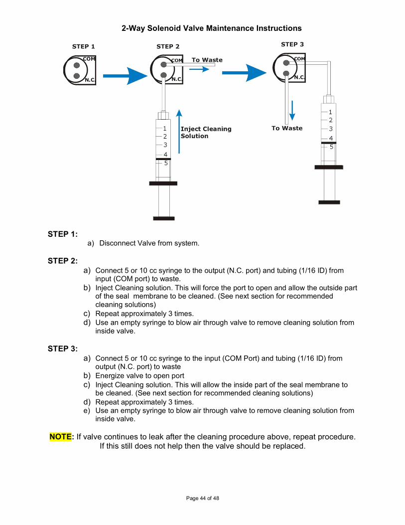
2-Way Solenoid Valve Maintenance Instructions
STEP 1:
a) Disconnect Valve from system.
STEP 2:
a) Connect 5 or 10 cc syringe to the output (N.C. port) and tubing (1/16 ID) from input (COM port) to waste.
b) Inject Cleaning solution. This will force the port to open and allow the outside part of the seal membrane to be cleaned. (See next section for recommended cleaning solutions)
c) Repeat approximately 3 times. d) Use an empty syringe to blow air through valve to remove cleaning solution from
inside valve.
STEP 3:
a) Connect 5 or 10 cc syringe to the input (COM Port) and tubing (1/16 ID) from output (N.C. port) to waste
b) Energize valve to open port c) Inject Cleaning solution. This will allow the inside part of the seal membrane to
be cleaned. (See next section for recommended cleaning solutions) d) Repeat approximately 3 times. e) Use an empty syringe to blow air through valve to remove cleaning solution from
inside valve.
NOTE: If valve continues to leak after the cleaning procedure above, repeat procedure.
If this still does not help then the valve should be replaced.
Page 45 of 48
Recommended Cleaning Solutions for Lee Co. Solenoid Valves
After using a system that uses solenoid valves, you might experience mixing of your solutions. This occurs when the solenoid does not seal properly. There are many causes for a solenoid valve to leak. The best preventative is to clean the valve thoroughly whenever an experiment is concluded or when there will be a break of longer than 1 day before the valve is used again. In the previous page there are instructions on how to clean the solenoid valves thoroughly. The type of cleaning solution will depend on the type of solutions that are used in the experiment. Below are some recommended solutions that can be used for cleaning solenoid valves. 1. Distilled water: For general flushing of valves. 2. Isopropyl Alcohol: For loosening particles that are stuck (due to use of “sticky”
solutions) in valve 3. Diluted white vinegar: To loosen any build up of minerals in the valve mechanism.
Page 46 of 48
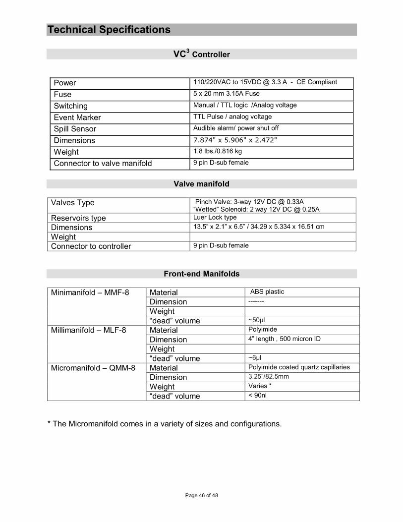
Technical Specifications
VC3 Controller
Power 110/220VAC to 15VDC @ 3.3 A - CE Compliant
Fuse 5 x 20 mm 3.15A Fuse
Switching Manual / TTL logic /Analog voltage
Event Marker TTL Pulse / analog voltage
Spill Sensor Audible alarm/ power shut off
Dimensions 7.874" x 5.906" x 2.472"
Weight 1.8 lbs./0.816 kg
Connector to valve manifold 9 pin D-sub female
Valve manifold
Valves Type Pinch Valve: 3-way 12V DC @ 0.33A “Wetted” Solenoid: 2 way 12V DC @ 0.25A
Reservoirs type Luer Lock type
Dimensions 13.5” x 2.1” x 6.5” / 34.29 x 5.334 x 16.51 cm
Weight
Connector to controller 9 pin D-sub female
Front-end Manifolds
Minimanifold – MMF-8 Material ABS plastic
Dimension -------
Weight
“dead” volume ~50µl
Millimanifold – MLF-8 Material Polyimide
Dimension 4” length , 500 micron ID
Weight
“dead” volume ~6µl
Micromanifold – QMM-8 Material Polyimide coated quartz capillaries
Dimension 3.25”/82.5mm
Weight Varies *
“dead” volume < 90nl
* The Micromanifold comes in a variety of sizes and configurations.
Page 47 of 48
LIMITED WARRANTY for Valves ALA Scientific Instruments agrees to warranty Lee Company Valves for 30 days from date of invoice. The Lee Company Certifies the functionality of each valve shipped to ALA Scientific Instruments. The valves are again tested at ALA Scientific when they are incorporated into the different systems that use them. It is recommended that the valves be checked upon receipt to determine any malfunctions. The following are the only agents approved to check valves: distilled water, Nitrogen or purified air. Any other agents used will void the warranty. Valves that have been used in actual experiments cannot be returned. Individual valves that malfunction within 30 days of invoice date will be replaced on a per case basis. ALA Scientific Instruments limits coverage to include repair or replacement of defective materials at our discretion. Buyer is responsible for the cost of return shipment. Inspection upon receipt is essential to receiving coverage should the instrument be damaged in shipment. Generally three days after receipt is the limit for such claims with the shipping company. ALA Scientific Instruments, Inc. is not responsible for damage occurring to, or from the use of this product that is inconsistent with its intended usage or this manual. It is the buyers’ responsibility to make sure that DC valves used with this instrument are run at the proper voltage and to use common sense in the operation of this product. This instrument, or any of its parts, is not approved for clinical use and has not been produced to such standards. Under the law, the VC3 system cannot be used on human subjects in any way. It has no clinical applications and is intended as a research instrument only. No guaranty of results is offered or implied by the use of this product. It is intended only for research purposes. Your rights under this warranty may vary from state to state and country to country.
Page 48 of 48
Warranty ALA Scientific Instruments, agrees to warranty this product for a period of one year from the date of delivery against any and all manufacturer’s defects in material and/or workmanship. Remedy will consist of repair or replacement at ALA’s discretion. All problems should be reported immediately so as not to jeopardize warranty coverage. ALA Scientific Instruments does not assume any liability based on the use of this product, whether correct or incorrect, except as specified under law. Warranty rights may vary from state to state. ALA Scientific Instruments will not warranty any of the plastic parts including 60cc reservoirs, all tubing and connectors, and magnetic stand parts. If the product does need repair, it must be returned to the factory freight prepaid (freight collect will be refused) and in clean condition. If returned parts have been in contact with any liquid substance, documentation must accompany those parts, regarding what substances were used. This product is intended for use in cellular and tissue research only. THIS EQUIPMENT IS NOT INTENDED NOR APPROVED FOR CLINICAL USE IN ANY WAY AT ALL.
Micromanifold is a trademark of ALA Scientific Instruments Inc.